

Page 1
Any and all SANYO products described or contained herein do not have specifications that can handle
applications that require extremely high levels of reliability, such as life-support systems, aircraft’s
control systems, or other applications whose failure can be reasonably expected to result in serious
physical and/or material damage. Consult with your SANYO representative nearest you before using
any SANYO products described or contained herein in such applications.
SANYO assumes no responsibility for equipment failures that result from using products at values that
exceed, even momentarily, rated values (such as maximum ratings, operating condition ranges,or other
parameters) listed in products specifications of any and all SANYO products described or contained
herein.
Thick Film Hybrid IC
Bidirectional DC Brush-Type
Motor Driver (I
O
=5A)
Ordering number:ENN5167
STK681-050
SANYO Electric Co.,Ltd. Semiconductor Company
TOKYO OFFICE Tokyo Bldg., 1-10, 1 Chome, Ueno, Taito-ku, TOKYO, 110-8534 JAPAN
Overview
The STK681-050 is a bidrectional DC brush-type motor
driver IC with brake function that incorporates MOSFET
power elements.
Applications
• PPC drum and scanner motor drivers
• LBP drum motor drivers
• Printer head and carriage motor drivers
• General DC motor applications
Features
• H-bridge output stage configuration employing 4
MOSFETs
• Independent TTL/CMOSlev el control for each MOSFET
(4-pin control)
• External signal control of forward, reverse and brake
opreration
• MOSFETs supporting 12A peak starting current and
13.5A peak brake current (F3 and F4 ON)
• DC input supporting saturation operation
• Only 1 charge pump electrolytic capacitor required, compared with the STK6875 which requires 2
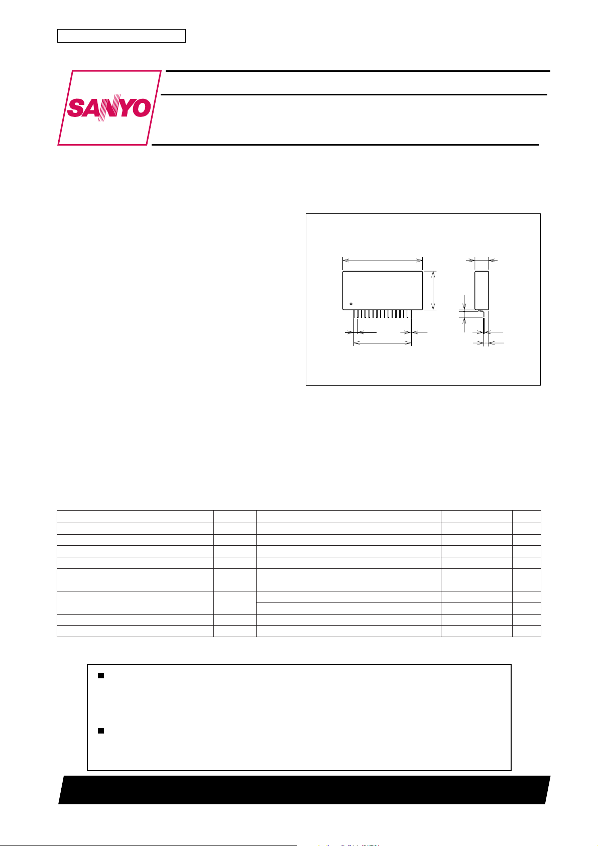
Package Dimensions
unit:mm
4163
[STK681-050]
53.0
116
2.54
15×2.54=38.1
0.5
25.5
9.0
1.0
0.4
4.0
2.9
SANYO : SIP16
Specifications
Maximum Ratings at Ta = 25˚C
retemaraPlobmySsnoitidnoCsgnitaRtinU
1egatlovylppusmumixaMV
2egatlovylppusmumixaMV
egatlovtupnimumixaMxamniV51,41,21,3,1sniP 01±V
tnerrucgnitratsrotommumixaMI
)NO2Fdna1F(
1tnerrucekarbrotommumixaM
2tnerrucekarbrotommumixaM
)NO4Fdna3F(
1noitapissidrewopelbawollAxam1dPssollatot,knistaehoN 2.5W
2noitapissidrewopelbawollAxam2dPTEFSOMrep,knistaehegralyrartibrA 52W
I
I
xam1langisoN 05V
CC
xam2langisoN 01V
CC
kaepsm07=htdiweslup,eslup1 21A
O
kaep1sm07=htdiweslup,eslup1 21A
BO
kaep2
BO
sm52=htdiweslup,eslup1 61A
sm001=htdiweslup,eslup1 5.31A
O2099TH (KT)/N0695HA (ID) No.5167–1/5
Continued on next page
Page 2
Continued from preceding page.
retemaraPlobmySsnoitidnoCsgnitaRtinU
ecnatsiserlamrehT
erutarepmetnoitcnuJxamjTTEFSOMreP 051
erutarepmetetartsbusgnitarepOxamcT 501
erutarepmetegarotSgtsT 521+ot04–
θ c-j
Allowable Operating Ranges at Ta = 25˚C
retemaraPlobmySsnoitidnoCsgnitaRtinU
1egatlovylppuSV
2egatlovylppuSV
egatlovtupnIniV51,41,21,3,1sniP 7+ot7–V
tnerructuptuorotoMI
tnerrucgnitratsrotoMI
)NO2Fdna1F(1tnerrucekarbrotoMI
)NO4Fdna3F(2tnerrucekarbrotoMI
ycneuqerfMWPf
ycneuqerftupniKLCf
egatlovgnisneSV
egatlovtupnietaGV
egatlovdnatshtiwTEFSOMV
CC
CC
O
DO
1sm001=htdiweslup,eslup1,evawelgnairT 11A
BO
2sm001=htdiweslup,eslup1,evawelgnairT 5.31A
BO
P
KLC
S
GI
STK681-050
TEFSOMreP 5
1langishtiW 24ot81V
2langishtiW 00.7ot57.4V
fycneuqerfMWP
zHk52=5A
P
sm002=t,eslup1 8A
ytud%06ot04 03ot01zHk
dnuorgdna5/4snipneewteB 6.0ot0V
GSdna21/3snipneewteB VCC2V
SSD
4F,3F,2F,1F 06V
˚C/W
˚C
˚C
˚C
03ot0zHk
Electrical Characteristics at Ta = 25˚C, VCC1=24V, VCC2=5.0V, f
retemaraPlobmySsnoitidnoC
1egatlovnoitarutastuptuO1tsVIO2F,1F,A5=57.050.1V
2egatlovnoitarutastuptuO2tsVIO4F,3F,A5=34.056.0V
tnerrucegakaeltuptuOI
tnerrucylppuSI
egatlovNOtupnIV
egatlovFFOtupnIV
tnerrucNOtupnII
tnerrucFFOtupnII
egatlovsaib-drawrofedoiDV
1emityaledNOnruTt
1emityaledFFOnruTt
2emityaledNOnruTt
2emityaledFFOnruTt
Note : All tests made using a constant-voltage supply.
L
OCC
HI
LI
HI
LI
IFA5=0.14.1V
F
1I(2F,1F
NO-d
1I(2F,1F
FFO-d
2I(4F,3F
NO-d
21I(4F,3F
FFO-d
V(21,3sniP
O
O
O
O
V8.0=51,41,21,3sniP0.27.20.4Am
51,41,1sniP0.2V
51,41,21,3,1sniP 08.0V
V(51,41,1sniP
HI
)V4.0=0.12.1Am
LI
)A5=6.0sµ
)A5=9.3sµ
)A5=2.0sµ
)A5=6.0sµ
=25kHz
CLK
sgnitaR
nimpytxam
nepo3nip,V8.0=51,41,21sniP
nepo21nip,V8.0=51,41,3sniP
)V7.2=12.024.0Am
001Aµ
2V
CC
tinU
No.5167–2/5
Page 3

Block Diagram
STK681-050
Test Circuit
Vst1, Vst2, I
CCO
, I
L
tseT
retemarap
1-1tsVhgiHwoLwoLnepO
2-1tsVwoLhgiHnepOwoL
1-2tsVwoLhgiHnepOwoL
2-2tsVhgiHwoLwoLnepO
I
OCC
IL1woLwoLwoLnepO
IL2woLwoLnepOwoL
41niP51niP21niP31niP
woLwoLwoLwoL
snoitidnoctupnI
High : VIH=2.0V
Low : VIL=0.8V
No.5167–3/5
Page 4

IIH, I
V
F
STK681-050
L
Sample Application Circuit
No.5167–4/5
Page 5

edoMANICNIBNIDNI
)evirderofeb(ybdnatSwoLwoLwoLwoL
WChgiHwoLwoLMWP
WCCwoLhgiHMWPwoL
ekarBwoLwoLV
edomtibihnI
hgiH
×
×
hgiH
2VCC2
CC
hgiH
×
High : VIH≥2.7V
Low : VIL≤0.4V
High level during PWM operation=VCC2
×=don’t care
STK681-050
×
hgiH
Specifications of any and all SANYO products described or contained herein stipulate the performance,
characteristics, and functions of the described products in the independent state, and are not guarantees
of the performance, characteristics, and functions of the described products as mounted in the customer's
products or equipment. To verify symptoms and states that cannot be evaluated in an independent device,
the customer should always evaluate and test devices mounted in the customer's products or equipment.
SANYO Electric Co., Ltd. strives to supply high-quality high-reliability products. However, any and all
semiconductor products fail with some probability. It is possible that these probabilistic failures could
give rise to accidents or events that could endanger human lives, that could give rise to smoke or fire,
or that could cause damage to other property. When designing equipment, adopt safety measures so
that these kinds of accidents or events cannot occur. Such measures include but are not limited to protective
circuits and error prevention circuits for safe design, redundant design, and structural design.
In the event that any or all SANYO products(including technical data,services) described or
contained herein are controlled under any of applicable local export control laws and regulations,
such products must not be exported without obtaining the export license from the authorities
concerned in accordance with the above law.
No part of this publication may be reproduced or transmitted in any form or by any means, electronic or
mechanical, including photocopying and recording, or any information storage or retrieval system,
or otherwise, without the prior written permission of SANYO Electric Co. , Ltd.
Any and all information described or contained herein are subject to change without notice due to
product/technology improvement, etc. When designing equipment, refer to the "Delivery Specification"
for the SANYO product that you intend to use.
Information (including circuit diagrams and circuit parameters) herein is for example only ; it is not
guaranteed for volume production. SANYO believes information herein is accurate and reliable, but
no guarantees are made or implied regarding its use or any infringements of intellectual property rights
or other rights of third parties.
This catalog provides information as of October, 1999. Specifications and information herein are subject
to change without notice.
PS No.5167–5/5
 Loading...