

SANYO STK6712BMK4 Datasheet
Thick Film Hybrid IC
Ordering number : EN4867A
O1895HA (OT)/N0794TH (OT) No. 4867-1/10
SANYO Electric Co.,Ltd. Semiconductor Bussiness Headquarters
TOKYO OFFICE Tokyo Bldg., 1-10, 1 Chome, Ueno, Taito-ku, TOKYO, 110-8534 JAPAN
Unipolar Fixed-Current Chopper-Type
4-Phase Stepping Motor Driver
STK6712BMK4
Overview
The STK6712BMK4 is a unipolar fixed-current choppertype 4-phase stepping motor driver hybrid IC (HIC) which
uses a MOSFET power device. The excitation sequence
signal is active low.
Applications
• Serial printer, line printer, and laser beam printer (LBP)
paper feed and carriage motor drivers
• PPC scanner and LBP paper feed drivers
• XY plotter pen drivers
• Industrial robot applications, etc.
Features
• This IC has the features of the STK6712BMK3, plus a
simultaneous input prevention circuit that protects the
IC from any malfunction of the excitation signal.
• Self-excitation design means chopping frequency is
determined by motor L and R. Supports chopping at
20 kHz or higher.
• Very low number of external components required.
• Wide operating supply voltage range (VCC1 = 18 to
42V)
• Excitation sequence signal is active low, and is TTL
level for direct interfacing to the microcomputer and
gate array.
• The unipolar design enables use as a driver for hybrid,
PW, or VR type stepping motors.
• Supports W1-2 phase operation, with a dual Vref pin.
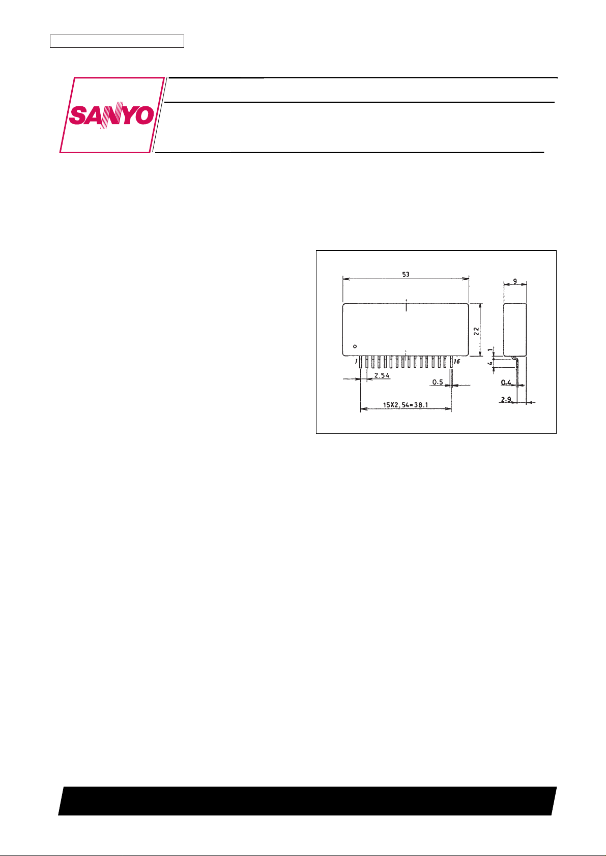
Package Dimensions
unit: mm
4129
[STK6712BMK4]

Specifications
Maximum Ratings at Ta = 25°C
Allowable Operating Ranges at Ta = 25°C
Junction Thermal Resistance
Electrical Characteristics at Tc = 25°C, VCC1 = 36 V, VCC2 = 5 V
Note: With constant voltage power supply.
Internal Equivalent Circuit
No. 4867-2/10
STK6712BMK4
Parameter Symbol Conditions Ratings Unit
Maximum supply voltage 1 V
CC
1 max No input signal 52 V
Maximum supply voltage 2 V
CC
2 max No input signal 7 V
Maximum phase current I
OH
max per phase, R/L = 5 Ω, 10 mH, 0.5 s 1 pulse, VCCinput 2.5 A
Substrate temperature Tc max 105 °C
Junction temperature Tj max 150 °C
Storage temperature Tstg –40 to +125 °C
Repeated avalanche resistance Ear max 38 mJ
Parameter Symbol Conditions Ratings Unit
Supply voltage 1 V
CC
1 With input signal 18 to 42 V
Supply voltage 2 V
CC
2 With input signal 4.75 to 5.25 V
Phase driver voltage resistance V
DSS
(min) 120 V
Phase current I
OH
max Duty 50% (max) 1.7 A
Parameter Symbol Conditions Ratings Unit
Power FET
θj-c 13.5 °C/W
Parameter Symbol Conditions min typ max Unit
Output saturation voltage V
ST
RL = 23 Ω, VIN= 0.8 V 1.1 1.5 V
Output current (average) Io ave R/L = 3.5 Ω/3.8 mH, V
IN
= 0.8 V per phase 0.45 0.50 0.55 A
Pin current dissipation (average) I
CC
2 Load, R = 3.5 Ω, L = 3.8 mH, VIN= 0.8 V per phase 15 25 mA
FET diode voltage Vdf Idf = 1.0 A 1.2 1.8 V
TTL input ON voltage V
IH
Input voltage when F1, 2, 3, 4 ON 2.0 V
TTL input OFF voltage V
IL
Input voltage when F1, 2, 3, 4 OFF 0.8 V
Switching time
t
ON
RL= 24 Ω, VIN= 0.8 V 100 ns
t
OFF
RL= 24 Ω, VIN= 0.8 V 0.2 µs

Sample Application Circuit
Note: For reference, when IOH≈ 1.1 A, RO1 = 6.8 kΩ and RO2 = 390 Ω.
IOH= K × × VCC2/R
7
K ≈ 1.3
R7 = R8 ≈ 0.33 Ω ± 3%
To reduce noise during motor hold, it is possible to mount CO1 ≈ 0.01 µF and CO2 = 100-200 pF. Normally these are
not required.
STK6712BMK4 Circuit Operation
Fig. 1 STK6712BMK4 Internal Equivalent Circuit
RO2
RO1 + RO2
No. 4867-3/10
STK6712BMK4
Output current waveform when phases are held (locked)
Measure output current values in this state.
 Loading...