

Page 1
Any and all SANYO products described or contained herein do not have specifications that can handle
applications that require extremely high levels of reliability, such as life-support systems, aircraft’s
control systems, or other applications whose failure can be reasonably expected to result in serious
physical and/or material damage. Consult with your SANYO representative nearest you before using
any SANYO products described or contained herein in such applications.
SANYO assumes no responsibility for equipment failures that result from using products at values that
exceed, even momentarily, rated values (such as maximum ratings, operating condition ranges,or other
parameters) listed in products specifications of any and all SANYO products described or contained
herein.
Thick Film Hybrid IC
4-Phase Stepping Motor Driver
Unipolar Self-Excitation Type (I
O
=1.5A)
Ordering number:ENN5165
STK6711AMK4
SANYO Electric Co.,Ltd. Semiconductor Company
TOKYO OFFICE Tokyo Bldg., 1-10, 1 Chome, Ueno, Taito-ku, TOKYO, 110-8534 JAPAN
1
16
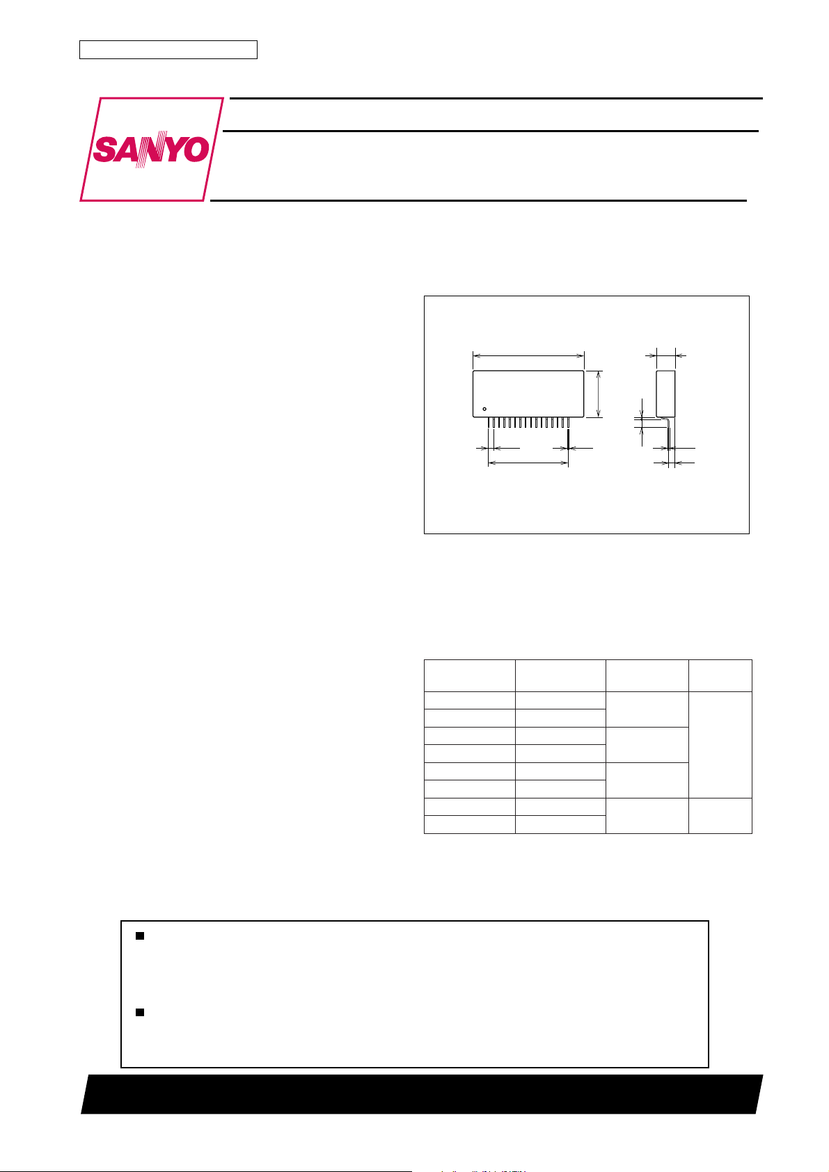
53.0
9.0
22.0
15×2.54=38.1
0.5
2.54
0.4
2.9
4.0
1.0
Overview
The STK6711AMK4 is a unipolar fixed-current
choppertype self-excitation 4-phase stepping motor driver
hybrid IC which uses MOSFET power devices. The exci-
tation sequence signal is active-high.
Applications
• Serial printer, line printer, and laser beam printer (LBP)
paper feed and carriage motor drivers.
• PPC scanner and LBP feed drivers.
Features
• Simultaneous ON prevention circuit built-in to prevent
driver breakdown due to simultaneous ON control signals from the control system’s microcontroller, etc.
• Self-excitation design means chopping frequency is determined by motor L and R. Supports chopping at 20kHz
or higher.
• Two 0.33Ω current detection resistors built-in for fixedcurrent chopping operation.
• Wide operating supply voltage range (18 to 42V for motor drive).
• Unipolar design enables use as a driver for hybrid, PM, or
VR-type stepping motors
• Supports W1-2 phase operation, with dual Vref pins.
Package Dimensions
unit:mm
4129
[STK6711AMK4]
SANYO : SIP16
Series Organization
The following devices from a series with differing excitation signal active level and output capacity. Some of the
following devices are under development. Contact your
Sanyo sales representative if you require more detailed in-
formation.
.oNepyTlangisnoitaticxE
4KMA1176KTShgih-evitcA
4KMB1176KTSwol-evitcA
4KMA2176KTShgih-evitcA
4KMB2176KTSwol-evitcA
4KMA3176KTShgih-evitcA
4KMB3176KTSwol-evitcA
4KMA4176KTShgih-evitcA
4KMB4176KTSwol-evitcA
tnerructuptuO
)esahprep(
A5.1
A7.1
A0.3
A0.4
epyT
-fleS
noitaticxe
dexiF
noitaticxe
N0199TH (KT)/N0695HA (ID) No.5165–1/5
Page 2
STK6711AMK4
Specifications
Maximum Ratings at Ta = 25˚C
retemaraPlobmySsnoitidnoCsgnitaRtinU
1egatlovylppusmumixaMV
2egatlovylppusmumixaMV
tnerrucesahpmumixaMI
ytilibapacgnildnahehcnalavadetaepeRxamraE 83Jm
erutarepmetnoitcnuJxamjT 051
erutarepmetetartsbusgnitarepOxamcT 501
erutarepmetegarotSgtsT 521+ot04–
Allowable Operating Ranges at Ta = 25˚C
retemaraPlobmySsnoitidnoC
1egatlovylppuSV
2egatlovylppuSV
egatlovdnatshtiwrevirdesahPV
tnerrucesahPI
Electrical Characteristics at Ta = 25˚C, VCC1=36V, VCC2=5V
retemaraPlobmySsnoitidnoC
egatlovnoitarutastuptuOtsVRL32= Ω V4.2=niV,4.19.1V
tnerructuptuoegarevAevaoI5.3=R:daoL Ω esahprep,V4.2=niV,Hm8.3=L,54.005.055.0A
niardtnerrucniPI
egatlovdrawrofedoidTEFfdVA0.1=fI2.18.1V
egatlovlevelhgihtupni-LTTV
egatlovlevelwoltupni-LTTV
emitgnihctiwS
Note : All tests are made using a constant-voltage supply.
xam1langistupnioN 25V
CC
xam2langistupnioN 7V
CC
xam5=R Ω 1,Hm01=L, × V,eslups5.0
HO
1langistupnihtiW8124V
CC
2langistupnihtiW57.400.552.5V
CC
SSD
xamytud%05 5.1A
HO
25.3=R:daoL Ω esahprep,V4.2=niV,Hm8.3=L,5152Am
CC
HI
LI
t
t
RL42= Ω V4.2=niV,05sn
NO
RL42= Ω V4.2=niV,1.0sµ
FFO
deilppa2.2A
CC
˚C
˚C
˚C
sgnitaR
nimpytxam
001V
sgnitaR
nimpytxam
NO4F,3F,2F,1FnehwegatlovtupnI0.2V
FFO4F,3F,2F,1FnehwegatlovtupnI 8.0V
tinU
tinU
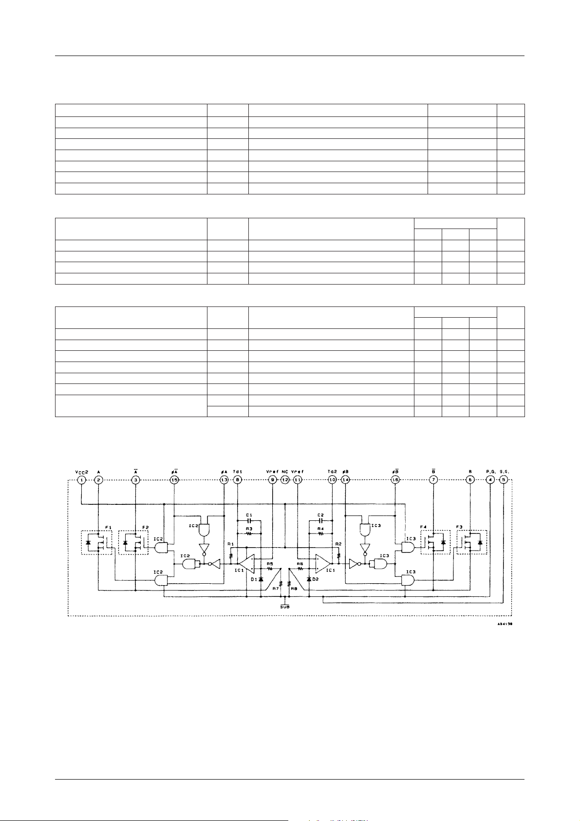
Equivalent Circuit
No.5165–2/5
Page 3

STK6711AMK4
Test Circuit
Vst loave
ICC2 Vdf
tON, t
OFF
No.5165–3/5
Page 4

Sample Application Circuit
STK6711AMK4
Motor Current
The following figure shows the motor current waveform
when all 4-phase inputs are locked.
The motor current is set by the Vref v oltag e which is deter mined by the resistors RO1 and RO2 connected to pins 9
and 11. IOH and Vref are related as sho wn in the following
equations, where K is a correction coefficient for actual
measurement.
IOH = K × ×
Vref = × VCC2
K ≈ 1.2 and R7 = R8 ≈ 0.33Ω±3%
RO2
RO1+RO2
RO2
RO1+RO2
VCC2
R7
Motor Hold Noise Countermeasures
(CO1 and CO2 Capacitors)
During motor hold, there may be cases where the motor
generates audible noise. In this case, capacitors CO1 ≈
0.01µF and CO2 ≈ 100 to 200pF can be added to prevent
this noise as shown in the Sample Application Circuit.
During normal operation, howev er, these capacitors are not
necessary .
Reference values are such that RO1=6.8kΩ and RO2=390Ω
at IOH ≈ 1A.
No.5165–4/5
Page 5

STK6711AMK4
Specifications of any and all SANYO products described or contained herein stipulate the performance,
characteristics, and functions of the described products in the independent state, and are not guarantees
of the performance, characteristics, and functions of the described products as mounted in the customer's
products or equipment. To verify symptoms and states that cannot be evaluated in an independent device,
the customer should always evaluate and test devices mounted in the customer's products or equipment.
SANYO Electric Co., Ltd. strives to supply high-quality high-reliability products. However, any and all
semiconductor products fail with some probability. It is possible that these probabilistic failures could
give rise to accidents or events that could endanger human lives, that could give rise to smoke or fire,
or that could cause damage to other property. When designing equipment, adopt safety measures so
that these kinds of accidents or events cannot occur. Such measures include but are not limited to protective
circuits and error prevention circuits for safe design, redundant design, and structural design.
In the event that any or all SANYO products(including technical data,services) described or
contained herein are controlled under any of applicable local export control laws and regulations,
such products must not be exported without obtaining the export license from the authorities
concerned in accordance with the above law.
No part of this publication may be reproduced or transmitted in any form or by any means, electronic or
mechanical, including photocopying and recording, or any information storage or retrieval system,
or otherwise, without the prior written permission of SANYO Electric Co. , Ltd.
Any and all information described or contained herein are subject to change without notice due to
product/technology improvement, etc. When designing equipment, refer to the "Delivery Specification"
for the SANYO product that you intend to use.
Information (including circuit diagrams and circuit parameters) herein is for example only ; it is not
guaranteed for volume production. SANYO believes information herein is accurate and reliable, but
no guarantees are made or implied regarding its use or any infringements of intellectual property rights
or other rights of third parties.
This catalog provides information as of November, 1999. Specifications and information herein are subject
to change without notice.
PS No.5165–5/5
 Loading...