

Sanyo SRT-7168P Instruction Manual
INSTRUCTION MANUAL
SRT-7168P
Real Time Video Recorder English
Real Time-Videorecorder
Enregistreur vidéo en temps réel
Deutsch
Français
Videograbador en tiempo real Español
Videoregistratore in tempo reale Italiano
Please read this manual carefully before connecting your VCR and operating it for the first time.
Be sure to read carefully and follow all the PRECAUTIONS on page 1.
Keep the manual in a safe place for future reference.

PRECAUTIONS
WARNING: TO REDUCE THE RISK OF FIRE OR
ELECTRIC SHOCK, DO NOT EXPOSE THIS
APPLIANCE TO RAIN OR OTHER MOISTURE.
To avoid electrical shock, do not open the cabinet.
Refer servicing to qualified personnel only.
If the power supply cord (AC power cord) of this
appliance is damaged, it must be replaced. Return to
a SANYO Authorised Service Centre for replacement
of the cord.
Location
For safe operation and satisfactory performance of your
VCR, keep the following in mind when selecting a place
for its installation:
œ Shield it from direct sunlight and keep it away from
sources of intense heat.
œ Avoid dusty or humid places.
œ Avoid places with insufficient ventilation for proper
heat dissipation. Do not block the ventilation holes of
the VCR. Do not place the unit on a carpet because
this will block the ventilation holes.
œ Install the VCR in a horizontal position only.
œ Avoid locations subject to strong vibrations.
œ Avoid moving the VCR between cold and hot
locations (see “Moisture Condensation Problems”,
this page).
œ Do not place the VCR directly on top of the TV, as
this may cause playback or recording problems.
Avoiding Electrical Shock and Fire
œ Do not handle the power cord with wet hands.
œ Do not pull on the power cord when disconnecting it
from an AC wall outlet. Grasp it by the plug.
œ If any liquid is spilled on the VCR, unplug the power
cord immediately and have the unit inspected at a
factory-authorised service centre.
œ Do not place anything directly on top of this VCR.
CAUTION: Do not put your hand or other objects in the
cassette loading slot because of risk of injury or
accident. Be sure to keep small children away from the
VCR.
Moisture Condensation Problems
Cause:
When the VCR is first installed, moved from a cold area
to a warm area or placed in a location with high
humidity, dew (moisture) may form in the unit. The Dew
indicator (À) blinks. If you operate the VCR with
dew inside, damage may result.
Prevention:
1 Make all necessary connections.
2 Plug the power cord into a 220 – 240 V AC outlet.
3 Do not operate the VCR for approximately 2 hours.
When the VCR reaches room temperature, the Dew
indicator (À) will turn off and the VCR will be ready
to operate.
Power on/stand-by mode
The power on/stand-by mode is selected by pressing
the STANDBY/ON button.
VCR display
Stand-by mode Power on mode
“Stand-by mode” is the condition in which only the time
is displayed.
Do not forget that even in the stand-by mode there is an
electrical voltage inside the VCR as long as it is
connected to a wall socket.
Disconnect the power cord from the wall socket if the
VCR is not to be used for a long time.
English 1
Bij dit produkt zijn batterijen
geleverd.
Wanneer deze leeg zijn, moet u
ze niet weggooien maar inleveren
als KCA.
FEATURES
CONTENTS
œ JOG/SHUTTLE operation
œ Can also be controlled through an RS-232C or
RS-485 connection
œ AC or DC power operation
œ Clog detection
œ High-speed Fast Forward/Rewind
œ Field recording/playback
œ 8, 24, 40, 64, 96, 128, 160 and 224-hour mode
recording (E-240)
œ 6, 18, 30, 48, 72, 96, 120 and 168-hour mode
recording (E-180)
œ In 8, 24, 40-hour modes audio recording is available
(E-240)
œ In 6, 18, 30-hour modes audio recording is available
(E-180)
œ Autorepeat recording
œ Series recording function
œ Alarm recording function
œ On-screen mode setting
œ Integrated time date generator
œ Day/Time search function
œ Alarm scan/search function
œ Forward/Reverse frame advance function
œ 30-day memory backup
œ Security lock
œ Recording check function
œ Automatic head cleaning function
PRECAUTIONS . . . . . . . . . . . . . . . . . . . . . . . . . . . . . . 1
FEATURES. . . . . . . . . . . . . . . . . . . . . . . . . . . . . . . . . . 2
ACCESSORIES . . . . . . . . . . . . . . . . . . . . . . . . . . . . . . 2
LOCATIONS OF CONTROLS AND
INDICATORS . . . . . . . . . . . . . . . . . . . . . . . . . . . . 3
CONNECTIONS . . . . . . . . . . . . . . . . . . . . . . . . . . . . . . 6
TYPES OF ON-SCREEN DISPLAYS AND
DISPLAY SEQUENCE . . . . . . . . . . . . . . . . . . . . . 8
SETTING THE LANGUAGE AND CLOCK. . . . . . . . . 10
CHANGING THE ON-SCREEN DISPLAY . . . . . . . . . 11
VIDEO CASSETTE TAPES . . . . . . . . . . . . . . . . . . . . 12
NORMAL RECORDING . . . . . . . . . . . . . . . . . . . . . . . 14
AUTOREPEAT RECORDING . . . . . . . . . . . . . . . . . . 17
ALARM RECORDING . . . . . . . . . . . . . . . . . . . . . . . . 18
PROGRAMME TIMER RECORDING. . . . . . . . . . . . . 21
RECORDING USING AN
EXTERNAL TIMER INPUT . . . . . . . . . . . . . . . . . 25
SERIES RECORDING . . . . . . . . . . . . . . . . . . . . . . . . 26
NORMAL PLAYBACK . . . . . . . . . . . . . . . . . . . . . . . . 27
SPECIAL PLAYBACK. . . . . . . . . . . . . . . . . . . . . . . . . 28
TAPE COUNTER . . . . . . . . . . . . . . . . . . . . . . . . . . . . 30
SETTING THE SECURITY LOCK . . . . . . . . . . . . . . . 30
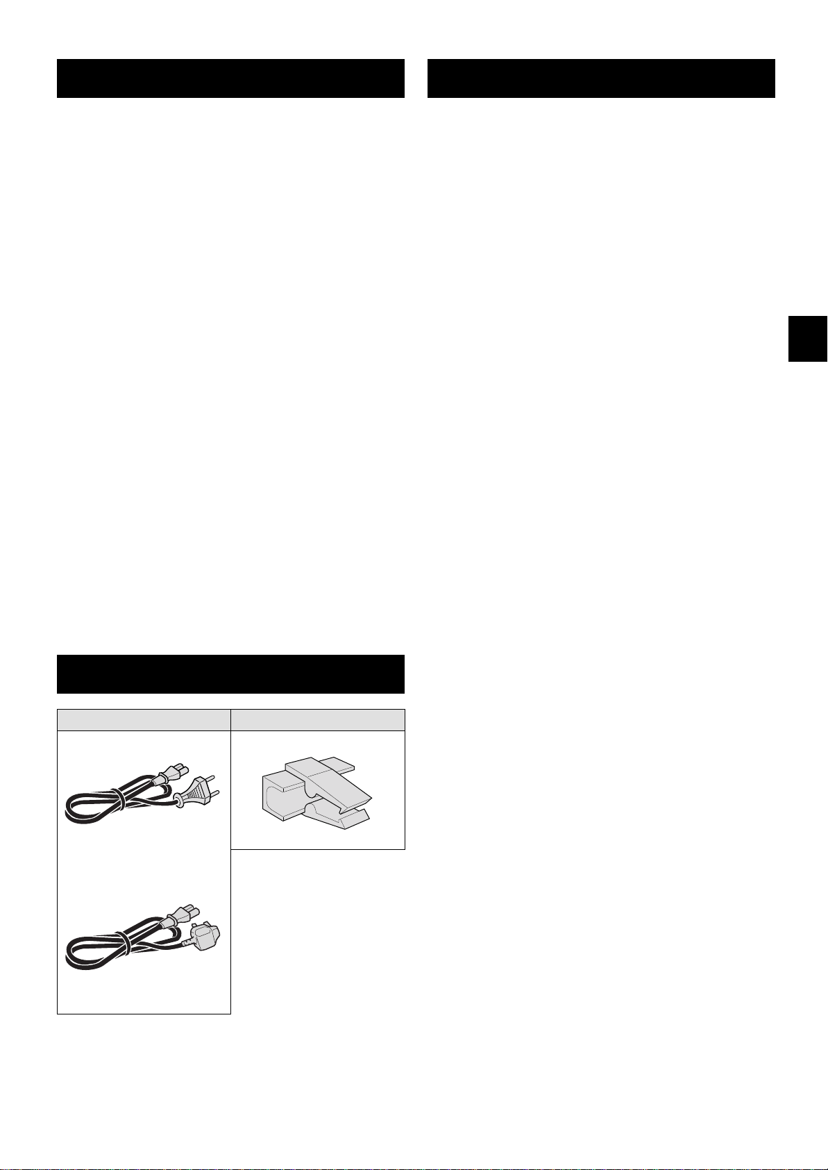
ACCESSORIES
Power cord Holder
---------------- or----------------
U.K. only
SETTING THE BUZZER. . . . . . . . . . . . . . . . . . . . . . . 31
CLOCK ADJUSTMENT . . . . . . . . . . . . . . . . . . . . . . . 31
SETTING THE RS-232C OR RS-485
DATA TRANSFER SPEED . . . . . . . . . . . . . . . . . 32
CHECKING POWER FAILURE,
FAILURE DUE TO CONDENSATION AND
USAGE DURATION . . . . . . . . . . . . . . . . . . . . . . 33
OUTPUT TERMINALS . . . . . . . . . . . . . . . . . . . . . . . . 34
MAINTENANCE . . . . . . . . . . . . . . . . . . . . . . . . . . . . . 37
TROUBLESHOOTING GUIDE . . . . . . . . . . . . . . . . . . 39
SPECIFICATIONS . . . . . . . . . . . . . . . . . . . . . . . . . . . 40
2 English
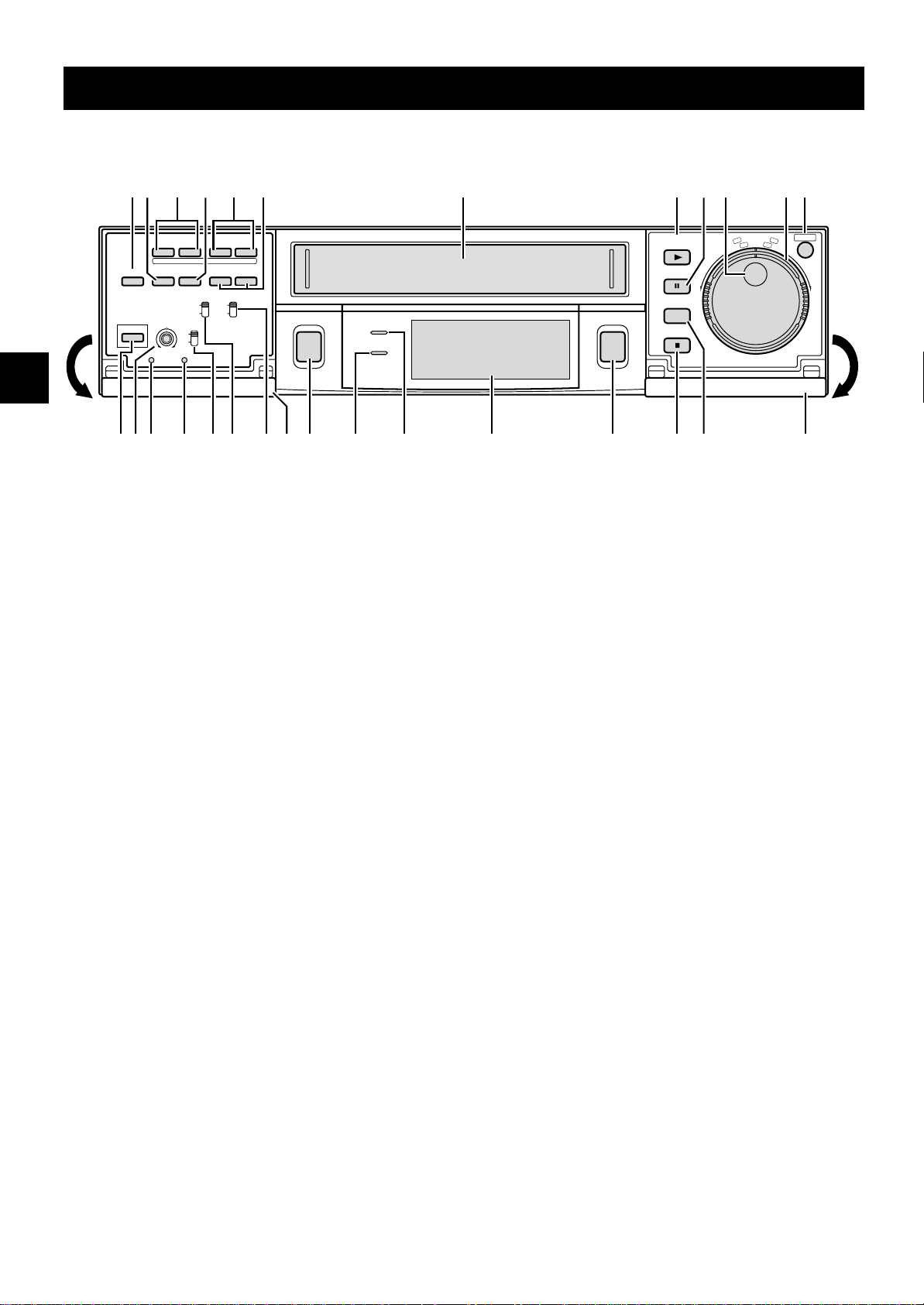
LOCA TIONS OF CONTROLS AND INDICA TORS
Front Panel
REC/PLAY
«
l
SPEED
lj
«
TRACKING
– V.STILL +
REPEAT
ON SCREEN
REC
OFF
OFF
ON
ON
TAPE
ALARM
SELECT SPEED DURATION
8H
E-240
24H
E-180
PROG.
NC
j
20S
CC
REC
a
STANDBY/ON
REPEAT
TIMER
STANDBY/ON
]
SHIFT
»
COUNTER
RESET MEMORY
SHARPNESS
SOFT SHARP
MENU RESET ALL RESET
RS
1
TIMER button
2 COUNTER RESET button
3 SHIFT ] or « (display position down or right) button
4
COUNTER MEMORY button
712 3 54 6 8 9 G
PLAY
(REC CHECK)
STILL
PAUSE
SEARCH
i
EJECT
STOP
F
T
T
U
L
E
H
S
j
l
G
O
J
,
»
W
E
R
JKLMNOPQU TVIW
M Digital display panel
N STANDBY/ON indicator
O REPEAT (autorepeat recording) indicator
P
REC (record) button
H
MENU
I
F
F
5 REC/PLAY SPEED l or j (decrease or increase
recording/playback speed mode) button
6
TRACKING/V. STILL – or + button
7 Cassette loading slot
8 PLAY (REC CHECK) button
9
STILL/PAUSE button
F JOG dial
G
SHUTTLE ring
H
MENU button
I Front door
J SEARCH button
K
STOP button
L EJECT button
Q REPEAT REC (autorepeat recording) switch
R
ON SCREEN switch
S
TAPE SELECT switch
T ALL RESET button
U
MENU RESET button
V SHARPNESS control
W
STANDBY/ON button
NOTE:
œ Buttons 3 and 5 are also used for menu control.
English 3
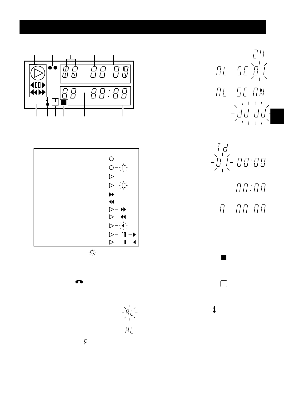
LOCATIONS OF CONTROLS AND INDICATORS
Digital Display
123 5
E
H
M
4
OFF
MS
G
1 Operation Indicators
œ They display the actual operation mode.
Operation Mode Indicator
Record (REC)
Record pause (REC PAUSE)
Playback (PLAY)
5
Mode display
œ Recording/playback
speed mode
œ Alarm search mode
œ Alarm scan mode
œ Dew display
6789F
5, 6
Mode display
œ Day/Time search
mode
Still image (STILL)
Fast forward (FF)
Rewind (REW)
Forward picture search
Reverse picture search
Reverse playback
Field shift forward
Field shift backward
œ Clog detection indicator
Flashes when the recording quality deteriorates
due to dirty VCR heads.
2
Cassette indicator
Comes on when a cassette is loaded.
3
Alarm indicator
Flashes when an alarm is
being recorded:
Comes on after the alarm
has been recorded:
4
Power failure indicator
Comes on after a power failure.
6
Counter display
œ Time display
œ Linear time counter
display
7
OFF indicator
Comes on when the tape end has been reached
after a recording, except during autorepeat
recording mode.
8
Counter memory indicator
Comes on when the counter memory function is
engaged.
9
Timer Recording indicator
Comes on when in timer recording stand-by mode,
or during a timer recording.
F
Security lock indicator
Comes on when the security lock is engaged.
G
External input indicator E
Comes on when recording using the EXT TIMER IN
input terminal.
OFF
HMS
M
4 English
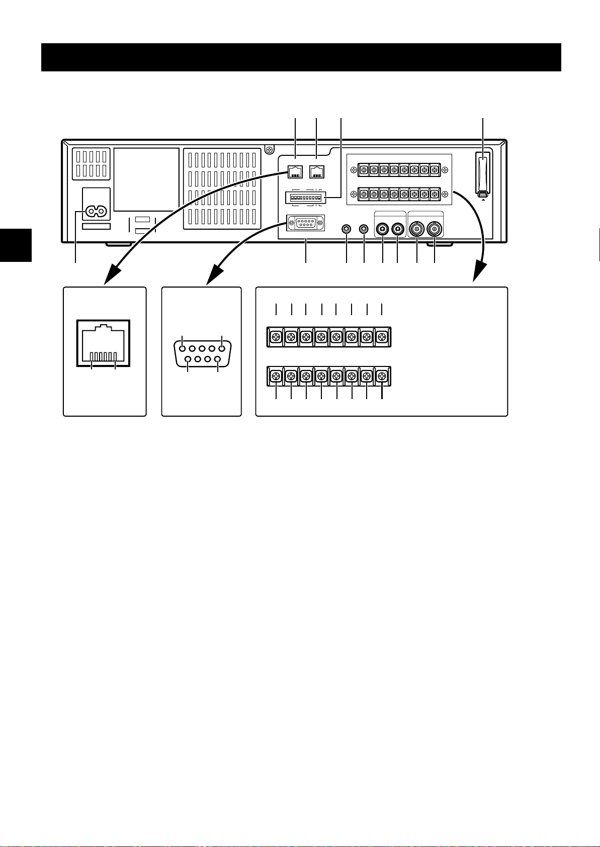
LOCATIONS OF CONTROLS AND INDICATORS
Back Panel
AC IN ~
X
Pin locations
(female) on the VCR
1 6
NOTE:
Do not connect to
phone line.
Pin locations
(male) on the VCR
15
96
1 2 3
EXT
WARNING
TIMER IN
RS485
ADDRESS
ON
OFF
RS232C
BA
485
232
TERMINATE
ON
OFF
REMOTE
COM
SERIES OUT/
NON REC OUT
OUT IN COM
MIC IN
W
456789FG
EXT
WARNING
TIMER IN COM
OUT IN COM
TAPE
OUT
END OUTSWOUT COM OUT IN
SERIES OUT/
SERIES
NON REC OUT
IN
TIMER
OUT
ALARM
DC 10-30V INCLOCK SET
–+
P O N M L K J I
TAPE
OUT
END OUTSWOUT COM OUT IN
SERIES
IN
AUDIO
OUT
IN
TIMER
OUT
VIDEO
IN OUT
ALARM
DC 10-30V INCLOCK SET
–+
QRSTUV
NOTES:
œThis terminal board
may be damaged by
5kg-cm or more torque
and using φ6mm-tip or
more size screwdrivers.
œPay attention to the
polarity of the DC 1030V input terminal
(“+”: red screw,
“–”: black screw).
H
PUSH
OPEN
1 RS485 A connector (RJ11 type)
2 RS485 B connector (RJ11 type)
3 DIP switches
œ Used when controlling the VCR through the
RS485 or the RS232C connectors.
4 EXT TIMER IN (external timer input) terminal
5 COM (common) terminal
6 WARNING OUT (warning output) terminal
7 TAPE END OUT (tape end output) terminal
8 SW OUT (switch output) terminal
9 COM (common) terminal
F ALARM OUT (alarm output) terminal
G ALARM IN (alarm input) terminal
H Battery compartment
I DC10-30V IN “+” input terminal
J DC10-30V IN “–” input terminal
K TIMER OUT (timer recording output) terminal
L COM (common) terminal
M SERIES IN (series recording trigger input) terminal
N SERIES OUT/NON REC OUT (series recording
trigger output/non recording output) terminal
O CLOCK SET IN (external clock set trigger input)
terminal
P CLOCK SET OUT (external clock set trigger output)
terminal
Q VIDEO OUT (video output) jack
R VIDEO IN (video input) jack
S AUDIO OUT (audio output) jack
T AUDIO IN (audio input) jack
U MIC IN (microphone input) jack
V REMOTE (remote control input) jack
W RS232C connector (D-sub 9-pin type)
X AC power input
English 5
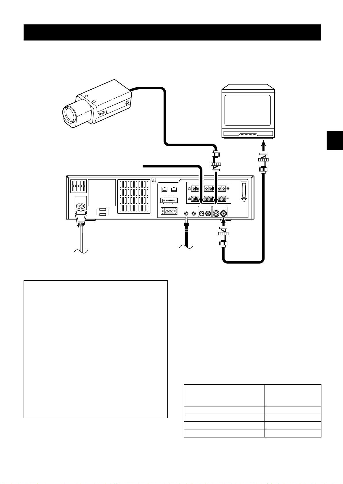
CONNECTIONS
Connect the video camera and monitor TV as shown in the figure below.
NOTE: Before making the connections, make sure the devices are disconnected from the power outlet.
Monitor TV (sold separately)
Video camera
(sold separately)
To
VIDEO IN
jack
TAPE
ALARM
TIMER
DC 10-30V INCLOCK SET
OUT
IN
–+
PUSH
VIDEO
OUT
IN OUT
OPEN
AC IN ~
From an external
audio source
RS485
ADDRESS
OFF
RS232C
EXT
WARNING
TIMER IN
COM
OUT
SERIES OUT/
OUT IN COM
NON REC OUT
AUDIO
IN
MIC IN
END OUTSWOUT COM OUT IN
SERIES
BA
TERMINATE
485
ON
ON
OFF
232
REMOTE
Power
cord
To outlet
IMPORTANT NOTE (U. K. Only)
The wires in the mains lead are coloured according
to the following code:
Blue: Neutral
Brown: Live
If the colours of the wires in the mains lead of this
apparatus do not correspond with the colour
markings identifying the terminals in your plug,
proceed as follows:
œ The wire which is coloured blue must be
connected to the terminal which is marked with
the letter N or coloured blue or black.
œ The wire which is coloured brown must be
connected to the terminal which is marked with
the letter L or coloured brown or red.
œ Do not connect either wire to the Earth terminal.
To
VIDEO
OUT
jack
To remote control
(sold separately)
Coaxial cable
(sold separately)
NOTES:
œ For more details, please refer to the manuals
accompanying all other devices. If the connections
are not made properly, it may cause a fire or damage
the equipment.
œ You can use a VA-RMN01 Remote Control Unit (sold
separately) to control remotely the VCR.
œ If there is no video signal when the power is turned
on, “NO VIDEO” will be displayed on-screen.
œ Use a DC power cord rated A.W.G 18 (1.25 mm
more.
œ The table below indicates the DC power source
output and DC power maximum cord lengths.
DC power source output DC power
maximum cord
lengths
18 V or more 2 A 6 m
12 ~ 16 V 3 A 6 m
10 V 5 A 6 m
10 V 4 A 2 m
2
) or
6 English
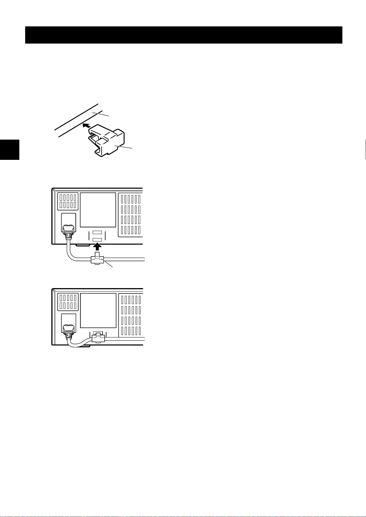
CONNECTIONS
Power cord
1 Plug the power cord (supplied) into the AC power
input (AC IN ~) on the VCR back panel. Insert the
plug straight and firmly.
2 Install the AC power cord into the holder.
AC power cord
Holder
3 Fix the holder to the VCR back panel.
About the memory reset
If the VCR location is changed or to cancel previous
settings, please reset the memory as described below.
To reset the memory, press the ALL RESET button.
NOTE:
œ The time and date will be reset, and the security lock
will be cancelled.
Holder
English 7
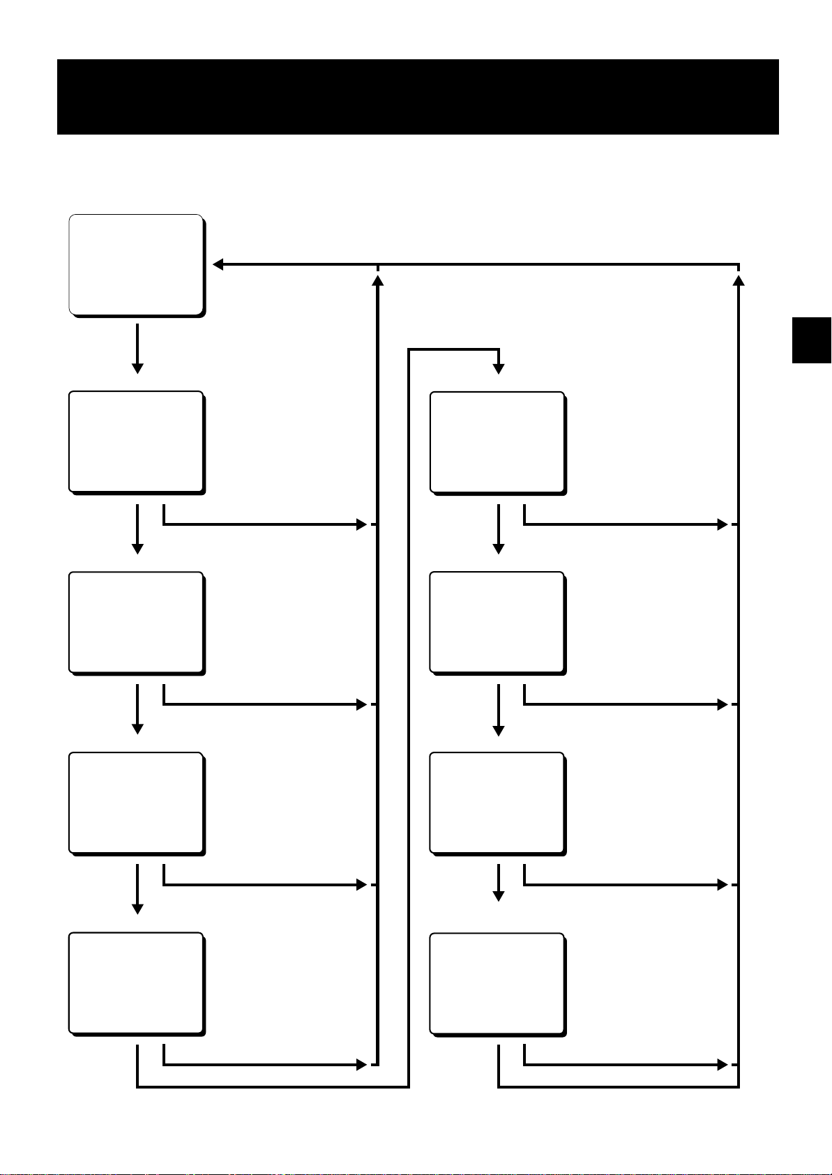
TYPES OF ON-SCREEN DISPLAYS AND
DISPLAY SEQUENCE
Reference pages are shown in square brackets.
Monitor TV screen (normal screen)
15-10-99 FRI 000
15:20:00 8
Set the ON SCREEN
switch to the “ON” position
Press the
MENU button
SET UP 1 menu
<SET UP 1>
Press the
MENU button
SET UP 2 menu
<SET UP 2>
Press the
MENU button
SET UP 3 menu
<SET UP 3>
[10, 35, 36]
DTo set various VCR functions
Press the SEARCH button
[11, 31]
DTo set various VCR functions
Press the SEARCH button
[18, 31, 13, 17, 34, 16, 26, 32]
DTo set various VCR functions
TIMER SET menu
<TIMER SET>
Press the
MENU button
HOLIDAY SET menu
<HOLIDAY SET>
Press the
MENU button
ALARM TIME menu
<ALARM TIME>
[21-25]
D
To set timer recordings
Press the SEARCH button
[23]
D
To set the holidays
Press the SEARCH button
[19]
D
To display the number, date and
time of the alarm recordings
Press the
MENU button
SET UP 4 menu
<SET UP 4>
Press the
MENU button
Press the SEARCH button
[35, 13, 15, 27] [33]
DTo set various VCR function
Press the SEARCH button
Press the
MENU button
Press the SEARCH button
POWER FAILURE/DEW/
USED TIME menu
D
<POWER FAILURE>
<DEW>
<USED TIME>
Press the
MENU button
Press the SEARCH button
To display the number and
duration of power failures
D
To display the number and duration
of failures due to condensation
D
To display the time used
8 English

TYPES OF ON-SCREEN DISPLAYS AND DISPLAY SEQUENCE
NOTES:
œ When a menu is displayed, recording will not be
possible.
œ Press the SEARCH or MENU button, the setting
procedure is now completed.
œ During recording or playback the menus cannot be
displayed.
œ To reset the settings of a menu to their original
values, select the desired menu then press the
MENU RESET button. The (USED TIME) menu data
cannot be reset.
œ To enter the settings use the JOG dial or SHUTTLE
ring.
Using the JOG dial and SHUTTLE ring
JOG dial
œ Put the tip of your index finger into the depression
then turn the dial in any direction.
œ When a menu is displayed, turn the dial clockwise
and the cursor will move to the right (or down). Turn
the dial counterclockwise and the cursor will move to
the left (or up).
SHUTTLE ring
œ When a menu is displayed, turn the ring of 10° or
more clockwise and the selected data setting will
change or the selected setting value will increase.
Turn the ring of 10° or more counterclockwise and
the selected data setting will change or the selected
setting value will decrease.
œ If held for 1 second or more the changes will be
made sequentially.
English 9

SETTING THE LANGUAGE AND CLOCK
Language Setting
English, French or German can be selected by the user.
1 Turn the power on to all devices used.
2 Press the MENU button to display the (SET UP 1)
menu.
@@@@@@@<SET@UP@1>
öSUMMER@TIME@SET@@@NO@USE
@@@@@@@@WEEK@MONTH@TIME
@ON@@@LST-SUN@@03@02:00
@OFF@@LST-SUN@@10@02:00
öOUTPUT@@@@@@@@SERIES
öCLOCK@SET
@01-01-00@SAT@@00:00:00
öREMOTE@@@@@@@@EJECT
öLANGUAGE-LANGUE-SPRACHE
@@@ENGLISH
3 Turn the JOG dial, until “ENGLISH” is flashing.
4 Turn the SHUTTLE ring to select the language of
your choice.
5 Press the SEARCH button to save the setting.
Clock setting
Example: To set the clock to October 15, 1999 at 3:20
PM (15:20).
1 Press the MENU button to display the (SET UP 1)
menu.
2 Turn the SHUTTLE ring, to set the auto summer
time/standard time adjustment.
NO USE . . . . No summer time/standard time
adjustment is made.
USE . . . . . . . The auto summer time/ standard
time adjustment is made.
3 Turn the JOG dial clockwise, until “LST” is flashing.
4 Set the day the summer time adjustment is made.
œ Turn the SHUTTLE ring to set the week, then
turn the JOG dial clockwise.
1ST, 2ND, 3RD, 4TH or LST (first, second, third,
fourth or last)
œ Turn the SHUTTLE ring to set the day of week,
then turn the JOG dial clockwise.
SUN, MON, TUE, ...... SAT (Sunday, Monday,
Tuesday....Saturday)
5 Turn the SHUTTLE ring to set the month the
summer time adjustment is made, then turn the
JOG dial clockwise.
01, 02,.....11, 12 (for January,
February......November, December)
6 Turn the SHUTTLE ring to set the time the summer
time adjustment is made.
7 Turn the JOG dial clockwise, until “LST” is flashing.
8 Following the same procedure as above (steps 4
to 6), set when the time is changed back from
summer time to standard time.
9 Turn the JOG dial clockwise, until the “CLOCK
SET” setting is flashing.
F Turn the SHUTTLE ring to set the day (ex: 15), then
turn the JOG dial clockwise.
ø
The day of week is set automatically.
G Turn the SHUTTLE ring to set the month (ex: 10),
then turn the JOG dial clockwise.
H Turn the SHUTTLE ring to set the year (ex: 99 for
1999), then turn the JOG dial clockwise.
ø
The last 2 digits only are displayed.
I Turn the SHUTTLE ring to set the hours (ex: 15 for
3 PM), then turn the JOG dial clockwise.
J Turn the SHUTTLE ring to set the minutes (ex: 20),
then turn the JOG dial clockwise.
@@@@@@@<SET@UP@1>
öSUMMER@TIME@SET@@USE
@@@@@@@@WEEK@MONTH@TIME
@ON@@@LST-SUN@@03@02:00
@OFF@@LST-SUN@@10@02:00
öOUTPUT@@@@@@@@SERIES
öCLOCK@SET
@15-10-99@FRI@@15:20:00
öREMOTE@@@@@@@@EJECT
öLANGUAGE-LANGUE-SPRACHE
@@@ENGLISH
K For accurate clock setting, turn the SHUTTLE ring
counterclockwise timed with a time broadcast, or
other accurate time signal, this will start the seconds
counting from 00.
L Press SEARCH button.
The setting procedure is now completed.
ø
NOTES:
œ Clock display is only 24 hours.
œ In STOP mode, press and hold the STOP button then
press the TRACKING/V.STILL– button to reset the
minutes and seconds to 00 (to the closest hour). For
example, between 13:30:00 and 14:29:59 the clock is
reset to 14:00:00.
10 English

CHANGING THE ON-SCREEN DISPLAY
Selecting the On-screen Display
You can select to display or not the date, time, the
number of alarm recordings and tape speed.
1 Turn the power on to all devices used.
2 Press the MENU button until the (SET UP 2) menu
is displayed.
@@@@@@@<SET@UP@2>
öDISPLAY
@@@DATE@@@@@@@@@@@Y
@@@TIME@@@@@@@@@@@Y
@@@ALARM@COUNT@@@@Y
@@@SPEED@@@@@@@@@@Y
öBUZZER
@@@ALARM@IN@@@@@@@Y
@@@TAPE@END@@@@@@@Y
@@@KEY@IN@@@@@@@@@N
@@@WARNING@@@@@@@@Y
3 Turn the JOG dial clockwise, until the desired item
for which the display function will be set is flashing.
4 Turn the SHUTTLE ring to set “Y” for the functions
described below.
DATE . . . . . . . . . . . The date is displayed
TIME . . . . . . . . . . . . The time is displayed
ALARM COUNT . . . The number of alarm
recordings is displayed
SPEED . . . . . . . . . . The recording/playback
speed mode is displayed
Changing the Date/Time Display
Position
1 Turn the power on to all input devices to the VCR.
2 Set the ON SCREEN switch to the “ON” position.
The date and time are displayed.
ø
15-10-99@FRI@000
15:20:00@@@8
3 Press the SHIFT « (or ]) button.
The display will move towards the right (or the
ø
bottom).
NOTES:
œ If the SHIFT « (or ]) button is kept pressed for 1
second or more the display will move at a faster
speed.
œ The display position cannot be changed while
recording.
5 Press the SEARCH button to save the settings.
The setting procedure is now completed.
ø
NOTE:
œ If the ON SCREEN switch is set to the “ON” position,
the items for which “Y” is set are recorded. The items
for which “N” was set at step 4 above are not
recorded.
English 11
VIDEO CASSETTE TAPES
Use only video cassette tapes bearing the w logo.
This VCR was primarily designed for use with E-180 or
E-240 cassette tapes, it is recommended to use E-180
or E-240 standard grade VHS video cassette tapes for
optimal performance.
Handling Cassette Tapes
The cassette tapes should always be stored vertically,
in their cases, away from high temperatures, magnetic
fields, direct sunlight, dirt, dust and locations subject to
mold formation.
Do not tamper with the cassette mechanism and never
touch the tape with your fingers.
Protect the cassette tapes from shocks or strong
vibrations.
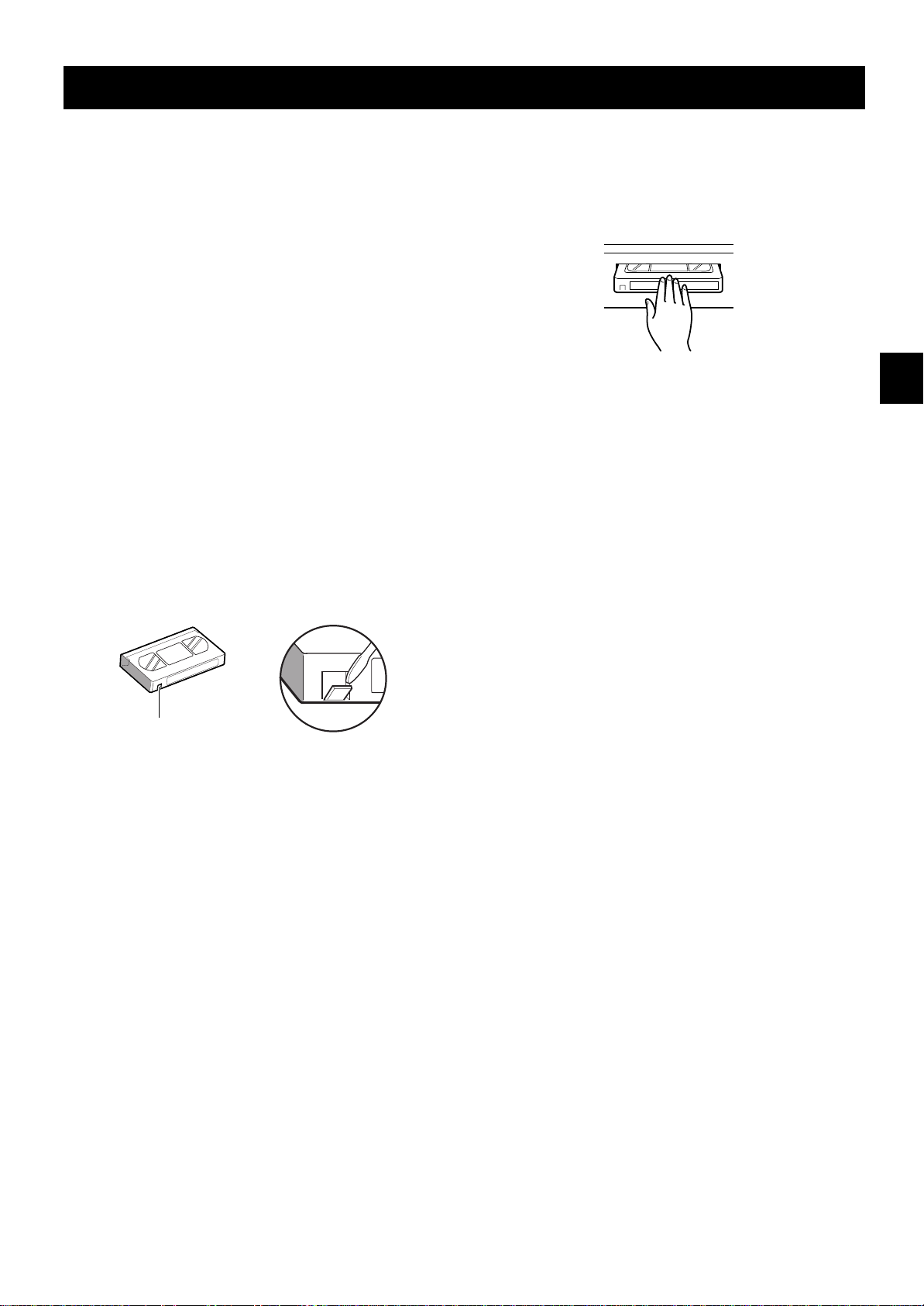
To Protect your Recordings
After having recorded a tape, if you wish to keep the
recording, use a flathead screwdriver to break off the
erasure-prevention tab on the cassette.
To record again on a tape without erasure-prevention
tab, cover the hole with adhesive tape.
Loading
1 Place the cassette, label side up, in the loading slot.
Gently push the centre of the cassette until it is
loaded automatically.
ø
The time display will switch to the reset counter
“0:00:00” display.
ø
After the cassette tape is loaded, a mechanism
will operate for about 5 seconds to check that
the tape has been threaded correctly and the
cassette indicator
period.
ø
When the cassette is loaded, if the tape has
been threaded correctly, the cassette indicator
“o”
will light on the digital display.
NOTE:
œ If you try to record on a cassette without
erasure-prevention tab, the VCR will eject the
cassette.
“o”
will blink during that
Erasure-prevention tab
Precautions concerning the video
cassette tapes
œ Do not use tapes that are damaged, tapes that have
been cut and repaired or tapes that have been
altered in any way.
œ Some rewinders may entangle the tape, and
therefore their use is not recommended.
œ When tapes are recorded over and over again, the
recording quality will deteriorate. Refer to
“Concerning the Number of Times Tapes can be
Rerecorded on” on page 15, and replace the tape
with a new tape as required.
Unloading
1 In stop mode, press the EJECT button.
The cassette is automatically ejected.
ø
NOTES:
œ Do not insert any object in the cassette loading slot,
as that may cause injury and damages to the VCR.
œ If your hand gets stuck in the cassette loading slot,
unplug the power cord and consult the dealer where
the unit was bought. Do not forcibly pull the hand out
as that may cause severe injuries.
12 English
 Loading...