

Page 1
Notice
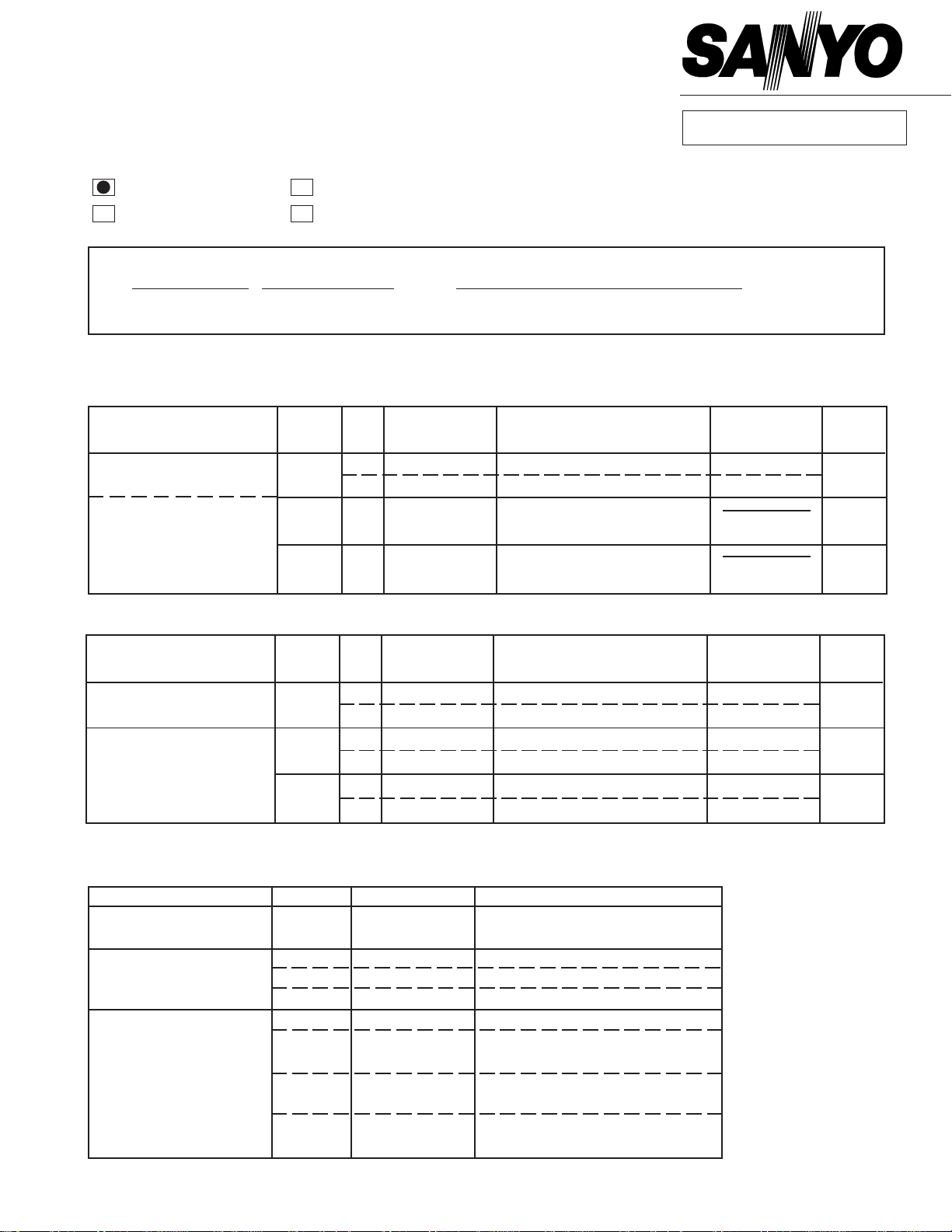
PRODUCTION CHANGECORRECTION
ADD INFORMATIONSERVICE FLASH
Please add this notice to the Service manual listed below.
FILE No.
Category : Real Time Video Recorder
Model Name Reference No. Destination
SRT-2400DC SS5310291 U.S.A.
SRT-2400DC SS5310291 Canada
The reason of change.
A : Misprint B : Quality Reliability C : Standardization D : Design
E : Deletion F : Addition G : Multiple Use
Date :Jun.25.2002
Interchange-
Section Reason
COMPL PWB,CP-1-A IC301 Old 410 395 6608 IC UPD 784927GF-201-3BA Wrong A
(Page 6) New 410 439 2207 IC UPD 784927GF-231-3BA Correct
(Page 9) RY101 Old 645 020 7105 RELAY E
When a serial number is before 42110300, please use the following replacement parts.
Loc.No. Part No. Description
645 009 3753 RELAY
RY201 Old 645 020 7105 RELAY E
645 009 3753 RELAY
ability
Interchange-
Section Reason
ACCESSORIES &
PACKING MAERIAL (Page 4)
CABINET & CHASSIS PARTS
(Page 4) New 613 194 1502 COMPL,COVER TOP SJC Yes with old
Loc.No. Part No. Description
Old 613 193 7802 INSTRUCTION MANUAL No D
New 613 197 4128 INSTRUCTION MANUAL No
6 Old 613 195 2775 COMPL,COVER TOP No D
12 Old 613 175 7646 COVER BOTTOM Wrong A
New 613 196 5461 COMPL,COVER BOTTOM Correct
ability
When a serial number is after 46510001, please use the following replacement parts.
(Other replacement parts are common. )
Loc.No. Part No. Description
ACCESSORIES &
PACKING MAERIAL
CABINET & CHASSIS PARTS
COMPL PWB,CT-1 613 194 0451
NU4QG/NA2,NA3 175 700 57,81
6 613 195 2775 COMPL,COVER TOP
28 613 198 0389 DEC INDICATOR
32 613 194 0451 COMPL PWB,CT-1
JK002 645 023 2916 TERMINAL,BOARD
CN001 645 006 0977 PLUG,10P (N.S.P.)
613 197 9871 INSTRUCTION MANUAL
(JACK)
(CONNECTOR)
(JUMPERS)
401 037 5004 MT-GLAZE 0.000 ZA 1/10W
SANYO Electric Co., Ltd.
Osaka,Japan
Reference No. SS5310291-01
Page 2

CIRCUIT DIAGRAMS &PRINTED WIRING BOARDS
This notice shows different portions concerning SS5310291
TABLE OF CONTENTS
Page
CP-1 BOARD (AD-A) AUDIO CIRCUIT DIAGRAM ........................................................................................ C2
CP-1 BOARD (VD-A) VIDEO CIRCUIT DIAGRAM ......................................................................................... C3
VD-1 P.W.B PATTERN .................................................................................................................................... C6
CT-1 are comon to the service manual for SRT-2400 (SM5310234)
About the circuit diagram AD-A and VD-A, diference from SS5310291 are the parts
which surrounded it with the circle.
As for the CP-1 P.W.B. there areno change from SS5310291.
About the VD-1 P.W.B. there was a design change and changed the board number
from 1AC4B10B79100D to 1AC4B10B79100E.
As for the VD-1 circuit diagram there areno change from SS5310291.
Page 3

documentation manual, user maintenance, brochure, user reference, pdf manual
This file has been downloaded from:
User Manual and User Guide for many equipments like mobile phones, photo cameras, monther board, monitors, software, tv, dvd, and othes..
Manual users, user manuals, user guide manual, owners manual, instruction manual, manual owner, manual owner's, manual guide,
manual operation, operating manual, user's manual, operating instructions, manual operators, manual operator, manual product,
 Loading...