

Page 1
INSTRUCTION MANUAL
Video Cassette Recorder
SRC-800
Please read this manual and accompanying “IMPORTANT SAFETY INSTRUCTIONS” sheet carefully before connecting your
VCR and operating it for the first time.
Be sure to read carefully and follow all the PRECAUTIONS on page 2.
Keep the manual in a safe place for future reference.
Page 2
PRECAUTIONS
CAUTION
RISK OF ELECTRIC SHOCK
DO NOT OPEN
CAUTION:
REFER SERVICING TO QUALIFIED SERVICE PERSONNEL.
WARNING:
TO REDUCE THE RISK OF ELECTRIC SHOCK,
DO NOT REMOVE COVER.
NO USER-SERVICEABLE PARTS INSIDE.
To reduce the risk of fire or electric
shock, do not expose this appliance to rain or
other moisture.
CAUTION:
Changes or modifications not expressly
approved by the manufa cturer may void the user’s
authority to operate this equipment.
Location
For safe operation and satisfactory performance of your
VCR, keep the following in mind when selecting a place
for its installation:
Shield it from direct sunlight and keep it away from
•
sources of intense heat.
Avoid dusty or humid places.
•
Avoid places with insufficient ventilation for proper heat
•
dissipation. Do not block the ventilation holes of the
VCR. Do not place the unit on a carpet because this will
block the ventilation holes.
Install the VCR in a horizontal position only.
•
Avoid locations subject to strong vibrations.
•
Avoid moving the VCR between cold and hot locations
•
(see “Moisture Condensation Problems”, this page).
Do not place the VCR directly on top of the TV, as this
•
may cause playback or recording problems.
THIS SYMBOL INDICATES THAT DANGEROUS
VOLTAGE CONSTITUTING A RISK OF
ELECTRIC SHOCK IS PRESENT WITHIN THIS
UNIT.
THIS SYMBOL INDICATES THAT THERE ARE
IMPORTANT OPERATING AND MAINTENANCE
INSTRUCTIONS IN THE LITERATURE
ACCOMPANYING THIS UNIT.
This equipment has been tested and found to comply with
the limits for a Class B digital device, pursuant to Part 15
of the FCC Rules. These limits are designed to provide
reasonable protection against harmful interference when
the equipment is operated in a commercial environment.
This equipment generates, uses, and can radiate radio
frequency energy and, if not installed and used in
accordance with the instruction manual, may cause
harmful interference to radio communications. Operation
of this equipment in a residential area is likely to cause
harmful interference in which case the user will be
required to correct the interference at his own expense.
Moisture Condensation Problems
Cause:
When the VCR is first installed, moved from a cold area to
a warm area or placed in a location with high humidity,
dew (moisture) may form in the unit. The Dew indicator
(À) blinks. If you operate the VCR with dew inside,
damage may result.
Prevention:
1 Make all necessary connections.
2 Plug the power cord into a 120V AC wall outlet.
3 Do not operate the VCR for approximately 2 hours.
When the VCR reaches room temperature, the Dew
indicator (À) will turn off and the VCR will be ready to
operation.
For the customers in Canada
Avoiding Electrical Shock and Fire
Do not handle the power cord with wet hands.
•
Do not pull on the power cord when disconnecting it
•
from an AC wall outlet. Grasp it by the plug.
If any liquid is spilled on the VCR, unplug the power
•
cord immediately and have the unit inspected at a
factory-authorized service center.
Do not place anything directly on top of this VCR.
•
“This digital apparatus does not exceed the Class B
limits for radio noise emissions from digital apparatus
as set out in the interference-causing equipment
standard entitled “Digital Apparatus”, ICES-003 of the
Department of Communications.”
2
Page 3

FEATURES
CONTENTS
High-speed Fast Forward/Rewind
•
8-hour mode recording audio playback
•
On-screen mode setting
•
Integrated time date generator
•
Day/Time search function
•
Forward field advance function
•
30-day memory backup
•
Security lock
•
Head-cleaning function
•
ACCESSORY
Power cord
PRECAUTIONS . . . . . . . . . . . . . . . . . . . . . . . . . . . . . . . 2
FEATURES. . . . . . . . . . . . . . . . . . . . . . . . . . . . . . . . . . . 3
ACCESSORY . . . . . . . . . . . . . . . . . . . . . . . . . . . . . . . . . 3
LOCATIONS OF CONTROLS AND
INDICATORS. . . . . . . . . . . . . . . . . . . . . . . . . . . . . . 4
CONNECTIONS . . . . . . . . . . . . . . . . . . . . . . . . . . . . . . . 7
TYPES OF ON-SCREEN DISPLAYS AND
DISPLAY SEQUENCE . . . . . . . . . . . . . . . . . . . . . . 8
SETTING THE LANGUAGE AND CLOCK. . . . . . . . . . . 9
CHANGING THE ON-SCREEN DISPLAY . . . . . . . . . . 10
VIDEO CASSETTE TAPES . . . . . . . . . . . . . . . . . . . . . 11
NORMAL RECORDING . . . . . . . . . . . . . . . . . . . . . . . . 12
SERIES RECORDING . . . . . . . . . . . . . . . . . . . . . . . . . 14
PLAYBACK. . . . . . . . . . . . . . . . . . . . . . . . . . . . . . . . . . 16
DAY/TIME SEARCH. . . . . . . . . . . . . . . . . . . . . . . . . . . 17
SETTING THE SECURITY LOCK . . . . . . . . . . . . . . . . 18
CLOCK ADJUSTMENT . . . . . . . . . . . . . . . . . . . . . . . . 18
SETTING THE CASSETTE EJECT MODE . . . . . . . . . 19
CHECKING USAGE DURATION, POWER
FAILURE AND FAILURE DUE TO
CONDENSATION . . . . . . . . . . . . . . . . . . . . . . . . . 20
MAINTENANCE . . . . . . . . . . . . . . . . . . . . . . . . . . . . . . 21
TROUBLESHOOTING GUIDE . . . . . . . . . . . . . . . . . . . 22
SPECIFICATIONS . . . . . . . . . . . . . . . . . . . . . . . . . . . . 23
WARRANTY . . . . . . . . . . . . . . . . . . . . . . . . . . . . . . . . . 24
3
Page 4
LOCATIONS OF CONTROLS AND
INDICATORS
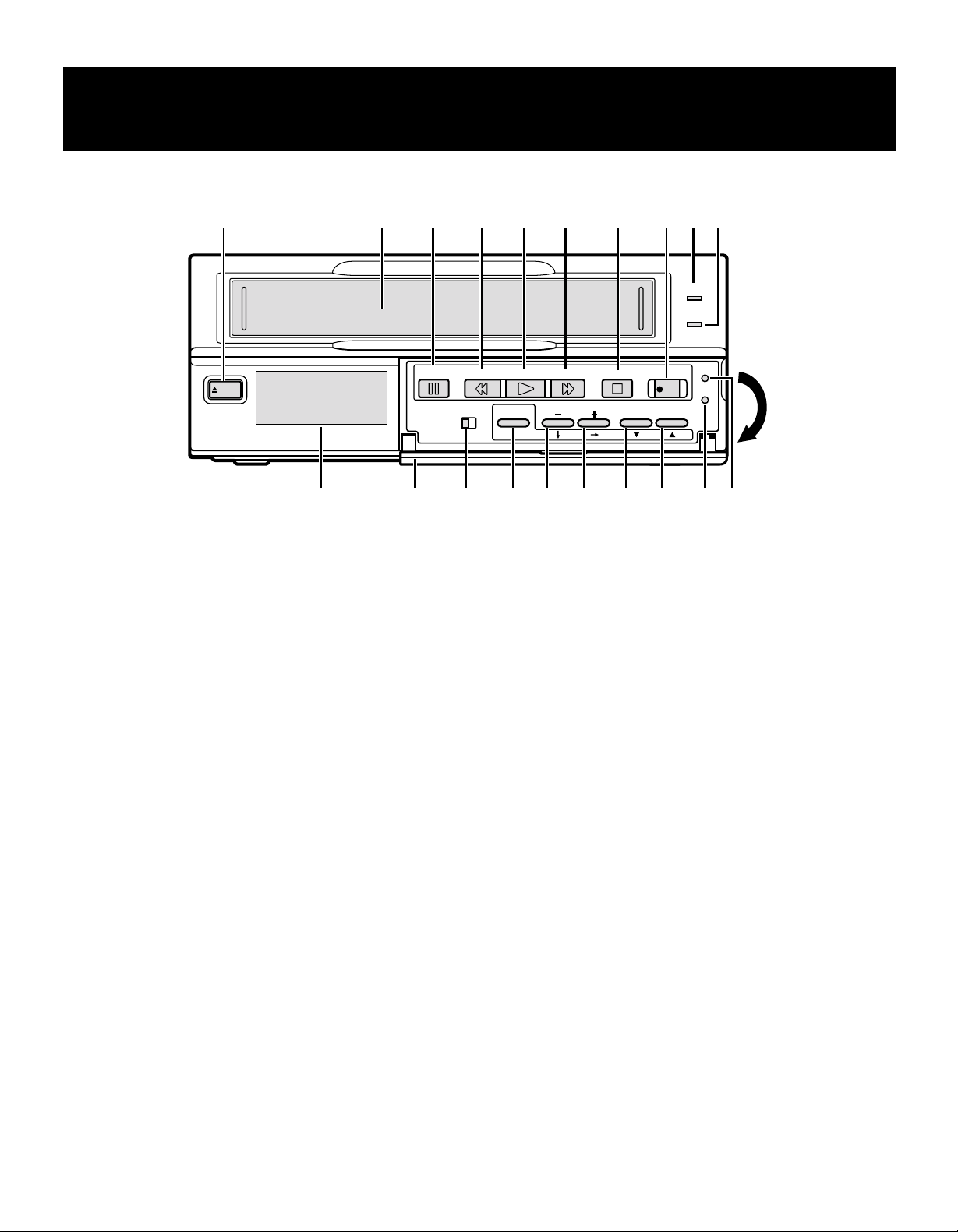
Front Panel
EJECT
1
EJECT button
2 Cassette loading slot
3 PAUSE/SEARCH button
4
REW (rewind/review) button
5
PLAY button
6
FF (fast forward/cue) button
7
STOP button
8 REC (record) button
9 STANDBY/ON indicator
F TAPE END indicator
21 3
PAUSE/
SEARCH
4 5 6 7 89F
STANDBY/ON
TAPE END
REW FF
PLAY
ON SCREEN
ON OFF
MENU
G
H
TRACKING
MENU RESET button
ALL RESET button
I COUNTER RESET, j button
When the counter is displayed on the digital display
panel, press this button to reset it to 0:00:00.
J l button
K TRACKING/V. STILL +, « button
L
TRACKING/V. STILL –, ] button
M MENU button
Press this button to display the menu.
Buttons I, J, K and L are used for menu control.
N ON SCREEN switch
V.STILL
STOP
REC
COUNTER
RESET
MENU
RESET
ALL
RESET
GHIJKLMNOP
O Front door
P Digital display panel
4
Page 5
LOCATIONS OF CONTROLS AND INDICATORS
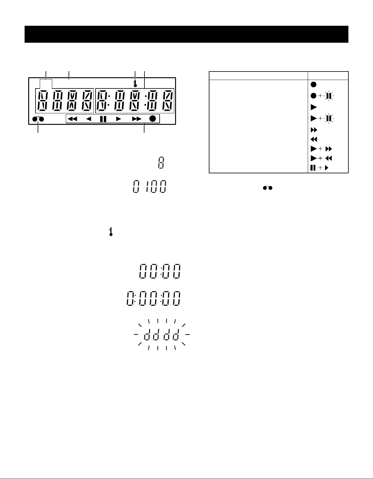
Digital Display
2
PT/D
M
1 Mode display
Recording/playback
•
speed mode
Day/Time search mode
•
2 Power failure indicator
Comes on after a power failure.
P
341
T/D
5
Operation Indicators
They display the actual operation mode.
•
Operation Mode Indicator
Record (REC)
Record pause (REC PAUSE)
Playback (PLAY)
Still image (STILL)
Fast forward (FF)
56
Rewind (REW)
Cue (CUE)
Review (REVIEW)
Field shift forward (FIELD SHIFT +)
6 Cassette indicator
Comes on when a cassette is loaded.
3 Security lock indicator
Comes on when the security lock is engaged.
4 Counter display
Time display
•
Linear time counter
•
display
Dew display
•
5
Page 6
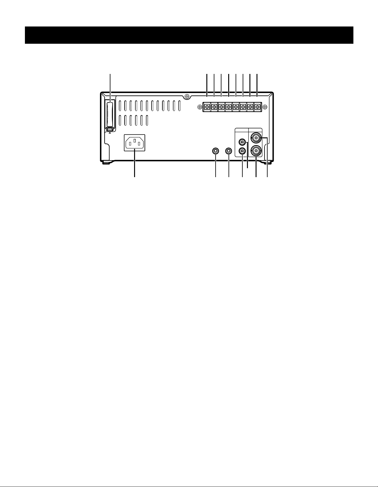
LOCATIONS OF CONTROLS AND INDICATORS
Back Panel
1 2 4 6 83 5 7 9
PUSH
OPEN
AC IN ~
1 Battery compartment cover
2 CLOCK SET OUT (external clock set trigger output)
terminal
3 CLOCK SET IN (external clock set trigger input)
terminal
4 COM (common) terminal
Common GND (ground) terminal when connecting
•
other terminals to external devices.
5 SERIES OUT (series recording trigger output) terminal
6 SERIES IN (series recording trigger input) terminal
7 Do not use
8 EJECT OUT (eject trigger output) terminal
9 EJECT IN (eject trigger input) terminal
CLOCK SET
OUT OUT IN
REMOTE
IN COM
SERIES
MIC IN
EJECT
OUT IN
AUDIO VIDEO
IN
IN
OUT
OUT
H
IJKL
FG
F VIDEO IN (video input) jack
G VIDEO OUT (video output) jack
H AUDIO IN (audio input) jack
I AUDIO OUT (audio output) jack
J MIC IN (microphone input) jack
K REMOTE (remote control input) jack
You can use a VA-RMN01 Remote Control Unit
•
(sold separately) to control remotely the VCR.
NOTES:
The functions not available on the VCR will not
•
operate.
The MENU button on the VA-RMN01 will function
•
as the EJECT button on the VCR.
L AC Power input
6
Page 7
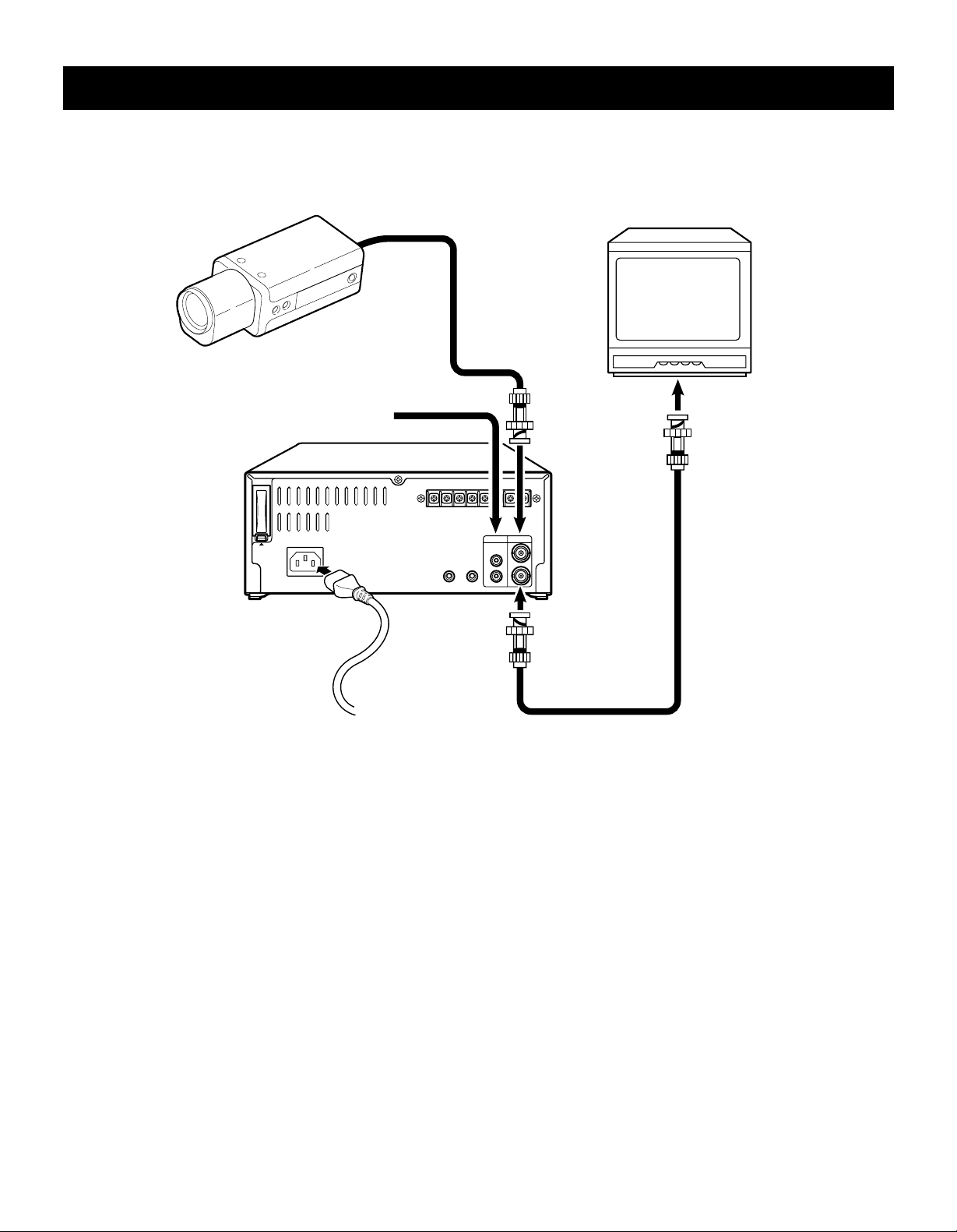
CONNECTIONS
Connect the video camera and monitor TV as shown in the figure below.
NOTE: Before making the connections, make sure all the devices are disconnected from the power outlet.
Monitor TV (sold separately)
Video camera
(sold separately)
From an external
audio source
CLOCK SET
IN COM
OUT OUT IN
AC IN ~
PUSH
OPEN
Power cord
REMOTE
VIDEO OUT
To outlet
Power Cord Installation
1 Plug the supplied power cord firmly into the AC power
input AC IN socket.
2 Insert the plug of this power cord into a outlet.
To
VIDEO IN
jack
SERIES
AUDIO VIDEO
IN
IN
OUT
MIC IN
OUT
To
jack
Coaxial cable
(sold separately)
NOTE:
For more details, please refer to the manuals
•
accompanying all other devices. If the connections are
not made properly, it may cause a fire or damage the
equipment.
About the memory reset
If the VCR location is changed or to cancel previous
settings, please reset the memory as described below.
The time and date will be reset.
To reset the memory, press the ALL RESET button.
7
Page 8
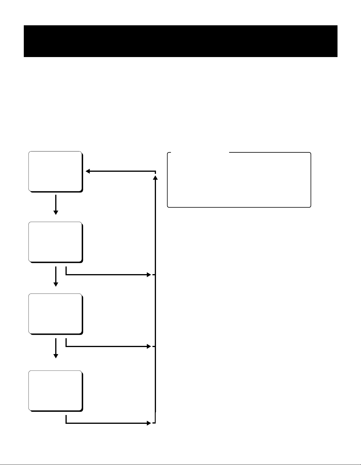
TYPES OF ON-SCREEN DISPLAYS AND
DISPLAY SEQUENCE
NOTES:
When a menu is displayed, recording will not be possible.
•
Press the PAUSE/SEARCH or MENU button, the setting procedure is now completed.
•
During recording or playback the menus cannot be displayed.
•
To reset the settings of a menu to their original values, select the desired menu then press the MENU RESET button.
•
The (USED TIME) menu data cannot be reset.
To enter the settings use the ], «, l or j buttons.
•
Monitor TV screen (normal screen)
10-15-99 FRI
15:20:00
Set the ON SCREEN
switch to the “ON” position
Press the
MENU button
SET UP 1 menu
<SET UP 1>
D
¤DAYLIGHT SET
¤CLOCK SET
¤LANGUAGE
Press the
MENU button
SET UP 2 menu
<SET UP 2>
To set daylight/standard time.
D
To set the date/time
D
To select the display language
Press the PAUSE/SEARCH button
D
To set various VCR function
Buttons functions
Button ]: To move down
Button «: To move to the right
Button l: To select numbers or switch settings
in reverse order
Button j: To select numbers or switch settings
in order
Press the
MENU button
POWER FAILURE, DEW
and USED TIME menu
<POWER FAILURE>
<DEW>
<USED TIME>
Press the
MENU button
Press the PAUSE/SEARCH button
Press the PAUSE/SEARCH button
DTo display the number and
duration of power failures
DTo display the number and duration
of failure due to condensation
DTo display the time used
8
Page 9

SETTING THE LANGUAGE AND CLOCK
Language Setting
English or French can be selected by the user.
1 Turn the power on to all devices used.
2 Press the MENU button to display the (SET UP 1)
menu.
<SET UP 1>
¤DAYLIGHT SET NO USE
WEEK MONTH TIME
ON 1ST-SUN 04 02:00
OFF LST-SUN 10 02:00
¤CLOCK SET
01-01-00 SAT 00:00:00
¤LANGUAGE
ENGLISH
3 Press the ] button, until “ENGLISH” is flashing.
4 Press the l (or j) button to select the language of
your choice.
5 When finished, press the PAUSE/SEARCH button to
save the settings.
Clock Setting
Example: To set the clock to October 15, 1999 at 3:20
PM (15:20).
1 Press the MENU button to display the (SET UP 1)
menu.
2 Press the l (or j) button, to set the auto
daylight/standard time adjustment.
NO USE. . . . . . . . . . No daylight/standard time
adjustment made.
USE . . . . . . . . . . . . . The auto daylight/standard
time adjustment made.
3 Press the ] button.
4 Set the day the daylight saving time adjustment is
made.
Press the l (or j) button to set the week, then
•
press the « button.
1ST, 2ND, 3RD, 4TH or LST (first, second, third,
fourth or last)
Press the l (or j) button to set the day of the
•
week, then press the « button.
SUN, MON, TUE, ...... SAT (Sunday, Monday,
Tuesday....Saturday)
6 Press the l (or j) button to set the time the daylight
saving time adjustment is made.
7 Press the ] button.
8 Following the same procedure as above (steps 4 to
6), set when the time is changed back from daylight
saving time to standard time.
9 Press the ] button.
F Press the l (or j) button to set the month (ex: 10),
then press the « button.
The day of week is set automatically.
°
G Press the l (or j) button to set the day (ex: 15), then
press the « button.
H Press the l (or j) button to set the year (ex: 99 for
1999), then press the « button.
NOTE:
The last 2 digits only are displayed.
•
I Press the l (or j) button to set the hours (ex: 15 for
3 PM), then press the « button.
J Press the l (or j) button to set the minutes (ex: 20),
then press the « button.
K For accurate clock setting, press the l button timed
with a time broadcast, or other accurate time signal,
this will start the seconds counting from 00.
<SET UP 1>
¤DAYLIGHT SET USE
WEEK MONTH TIME
ON 1ST-SUN 04 02:00
OFF LST-SUN 10 02:00
¤CLOCK SET
10-15-99 FRI 15:20:00
¤LANGUAGE
ENGLISH
L When finished, press the PAUSE/SEARCH button to
save the settings.
5 Press the l (or j) button to set the month the
daylight saving time adjustment is made, then press
the « button.
01, 02,.....11, 12 (for January,
February......November, December)
9
Page 10

CHANGING THE ON-SCREEN DISPLAY
Selecting the On-screen Display
You can select to display or not the date and time.
1 Turn the power on to all devices used.
2 Press the MENU button until the (SET UP 2) menu is
displayed.
<SET UP 2>
¤DISPLAY
DATE Y
TIME Y
ALARM COUNT Y
¤TAPE IN MODE STOP
¤TAPE END MODE REW
¤TAPE END OUT -3M
¤SERIES REC N
¤EJECT MODE EJECT 1
¤THREAD CHECK Y
3 Press the ] button, until the desired item for which
the display function will be set is flashing.
4 Press the l (or j) button to set “Y” for the functions
described below.
DATE . . . . . . . . . . . . The date is displayed
TIME . . . . . . . . . . . . The time is displayed
5 Press the PAUSE/SEARCH button, the normal
screen is displayed.
The setting procedure is now completed.
°
Changing the Date/Time Display Position
1 Turn the power on to all devices used.
2 Set the ON SCREEN switch to the “ON” position.
The date and time are displayed.
°
Date/Time display
10-15-99 FRI
15:20:00
3 Press the « (or ]) button.
The display will move towards the right (or the
°
bottom).
NOTES:
If the « (or ]) button is kept pressed for 1 second or
•
more the display will move at a faster speed.
The display position cannot be changed while recording.
•
NOTE:
If the ON SCREEN switch is set to the “ON” position,
•
the items for which “Y” is set are recorded. The items
for which “N” was set at step 4 above are not recorded.
10
Page 11

VIDEO CASSETTE TAPES
Use only video cassette tapes bearing the w logo. This
VCR was primarily designed for use with T-160 cassette
tapes, it is recommended to use T-160 VHS video
cassette tapes for optimal performance.
Handling Cassette Tapes
The cassette tapes should always be stored vertically, in
their cases, away from high temperatures, magnetic
fields, direct sunlight, dirt, dust and locations subject to
mold formation.
Do not tamper with the cassette mechanism and never
touch the tape with your fingers.
Protect the cassette tapes from shocks or strong
vibrations.
To Protect your Recordings
After having recorded a tape, if you wish to keep the
recording, use a flathead screwdriver to break off the
erasure-prevention tab on the cassette.
To record again on a tape without erasure-prevention tab,
cover the hole with adhesive tape.
Erasure-prevention tab
Unloading
1 In STOP mode, press the EJECT button.
The cassette is automatically ejected.
°
NOTES:
Do not insert any object in the cassette loading slot, as
•
that may cause injury and damages to the VCR.
If your hand gets stuck in the cassette loading slot,
•
unplug the power cord and consult the dealer where the
unit was bought. Do not forcibly pull the hand out as
that may cause severe injuries.
Setting the Action to Take When a
Cassette is Loaded
In the (SET UP 2) menu, you can set the mode the VCR
will go into when a cassette is loaded.
1 Press the MENU button until the (SET UP 2) menu is
displayed.
<SET UP 2>
¤DISPLAY
DATE Y
TIME Y
ALARM COUNT Y
¤TAPE IN MODE STOP
¤TAPE END MODE REW
¤TAPE END OUT -3M
¤SERIES REC N
¤EJECT MODE EJECT 1
¤THREAD CHECK Y
Loading
1 Place the cassette, label side up, in the loading slot.
Gently push the center of the cassette until it is
loaded automatically.
When the cassette is loaded, the cassette
°
indicator
The time display will switch to the reset counter
°
“0:00:00” display.
NOTE:
If you try to record on a cassette without
•
erasure-prevention tab, the VCR will eject the cassette.
“o”
will light on the digital display.
2 Press the ] button, until the “TAPE IN MODE” setting
is flashing.
3 Press the l (or j) button, to set the desired mode.
STOP . . . . . . . . . . . . Stays in stop mode
REC . . . . . . . . . . . . . Goes into recording mode
4 Press the PAUSE/SEARCH button to save the setting.
11
Page 12

NORMAL RECORDING
Normal Recording
1 Turn the power on to all devices used.
2 Load a cassette tape with erasure-prevention tab.
NOTE:
If in the (SET UP 2) menu, TAPE IN MODE is set
•
to “REC”, recording will start.
3 Set the ON SCREEN switch to the “ON” position.
4 Press the REC button.
The Record indicator
°
Recording starts.
°
5 To stop recording, press the STOP button.
NOTES:
A tape recorded on this VCR cannot be played back
•
completely on other SP mode only VCRs.
If you press on the REC button and the loaded cassette
•
has no erasure-prevention tab, the VCR will eject the
cassette.
During recording, the MENU button will not function
•
(the menu cannot be displayed).
(a)
lights.
[Recording Speed]
Recording
speed
8
TAPE COUNTER NOTES:
There is no tape counter indication for the blank
•
portions of the tape.
The tape counter indicates real hours, minutes and
•
seconds.
There may be a slight discrepancy between the position
•
shown on the tape counter and the actual tape position.
When rewinding the tape past the “0:00:00” position, a
•
minus (–) sign will be displayed.
Maximum recording
duration (with an T-160
cassette tape)
Standard
mode
8 hours 1/60 second Possible Continuous
Recording
interval
Audio
recording
Tape motion
Record Pause
Recording can be interrupted temporarily.
1 Press the PAUSE/SEARCH button during recording.
The Pause/Still indicator
°
NOTES:
The image appears on-screen but it is not recorded.
•
If a recording pause continues for 5 minutes or
•
more, the VCR will go into stop mode to avoid
damaging the tape.
( h )
blinks.
2 To resume recording, press the REC button, or press
the PAUSE/SEARCH button again.
12
Page 13

NORMAL RECORDING
Setting the Mode at the End of the Tape
In the (SET UP 2) menu, you can set the mode of the
VCR mode when the tape reaches the end during
recording.
1 Press the MENU button until the (SET UP 2) menu is
displayed.
<SET UP 2>
¤DISPLAY
DATE Y
TIME Y
ALARM COUNT Y
¤TAPE IN MODE STOP
¤TAPE END MODE REW
¤TAPE END OUT -3M
¤SERIES REC N
¤EJECT MODE EJECT 1
¤THREAD CHECK Y
2 Press the ] button, until the “TAPE END MODE”
setting is flashing.
3 Press the l (or j) button, to set the desired mode.
REW . . . . . . . . . . . . Rewinds the tape to the
beginning, then goes to stop
mode
STOP. . . . . . . . . . . . Goes to stop mode
4 Press the PAUSE/SEARCH button to save the
setting.
TAPE END Indicator Setting
1 Press the MENU button until the (SET UP 2) menu is
displayed.
<SET UP 2>
¤DISPLAY
DATE Y
TIME Y
ALARM COUNT Y
¤TAPE IN MODE STOP
¤TAPE END MODE REW
¤TAPE END OUT -3M
¤SERIES REC N
¤EJECT MODE EJECT 1
¤THREAD CHECK Y
2 Press the ] button, until the “TAPE END OUT”
setting is flashing.
3 Press the l (or j) button, to select the desired output
mode.
–3M . . . . . . . . . . . . . The TAPE END indicator
flashes when the tape
counter reaches “7:57:00”
and/or when the tape
reaches the end.
END . . . . . . . . . . . . . The TAPE END indicator
flashes when the tape
reaches the end.
4 Press the PAUSE/SEARCH button, the normal
screen is displayed.
NOTES:
If “TAPE END MODE” has been set to “REW”, the
•
TAPE END indicator will flash while the tape is
rewinding.
Press the EJECT, FF, REW or PLAY button to turn
•
the indicator off.
13
Page 14

SERIES RECORDING
Using 2 VCRs or more, the series recording function lets
you switch recording from one unit to the next (only with
VCRs of the same model as this one).
Series Recording Setup
1 Connect 2 VCRs or more as illustrated below.
2 Set the following items as indicated.
Item VCR No.1 VCR No.2
and on
Cassette tape Loaded Loaded
Operation mode Stop Stop
“SERIES REC” (in (SET
UP 2) menu)
Security lock Canceled Set
3 Press the REC button on VCR No.1.
Recording will start in series recording mode.
°
4 Set the security lock on VCR No.1.
Y (YES) Y (YES)
The SERIES OUT signal will be presence either at the
point when the counter reading is 7:57:00 or when VCR
No. 1 reaches the end of the tape, whichever is first. The
signal will stop 70 seconds after the tape end point of
VCR No. 1.
When this signal is received by VCR No. 2, it will start
recording. During the period when the SERIES OUT
signal is being received by VCR No. 2, if the STOP button
of VCR number 2 is accidentally pressed, VCR No. 2 will
go into the stop mode for an instant and then return to the
record mode.
To prevent this form occuring, the security lock of VCR
No. 2 should be set to the on condition.
When the end of the tape is reached on VCR, the tape
will rewind and then stop, if TAPE END MODE is set to
“REW”. (TAPE END indicator will be flashed until the
EJECT, FF, REW, PLAY or REC button is pressed.).
NOTES:
If the counter reading on VCR No.1 is 7:57:00 or more,
•
when the REC button is pressed (step 3), the
recording will start on VCR No.2.
If in the (SET UP 2) menu “SERIES REC” is set to “N”,
•
series recording will not be possible.
T-160 must be used for proper serial out operation.
•
The counter must start from the beginning of tape, or
•
the series recording out will not function properly.
Series recording connections
Video camera
VCR No.1
To COM
terminal
To
VIDEO IN
jack
To
VIDEO OUT
jack
To
SERIES OUT
terminal
VCR No.2
Monitor TV
SERIES OUT
To COM
terminal
To
terminal
To VIDEO OUT jack
(VCR)
To
VIDEO IN
jack
To
VIDEO OUT
jack
To VIDEO IN jack
(VCR No. 3)
To
SERIES IN
terminal
To SERIES IN terminal
(VCR No. 3)
To COM terminal
(VCR No. 3)
14
Page 15

SERIES RECORDING
Continous Loop Recording Setup
It is possible to configure at least two this VCR for
continous loop recording.
Under loop recording when the recording finishes on the
first unit, the new recording will start on the second unit.
When the recording finishes on the second unit, recording
will start on the first unit.
1 The SERIES OUT terminal of VCR No.2 and the
SERIES IN terminal No.1 should be connected (See
diagram).
2 Set the following items as indicated.
Item VCR No.1 VCR No.2
and on
Cassette tape Loaded Loaded
Operation mode Stop Stop
“TAPE END MODE” (in
(SET UP 2) menu)
“SERIES REC” (in (SET
UP 2) menu)
Security lock Canceled Set
REW REW
Y (YES) Y (YES)
NOTES:
The “TAPE END MODE” in (SET UP 2) menu should
•
be set to "REW" for both units without fail.
The TAPE END indicator will continue to bink when the
•
end of the first tape is rearched.
Under loop conditions, the tape will continue to
•
re-record. If you need to keep the recorded infomation,
please remove the tape after recording is complete and
insert and new tape.
3 Press the REC button on VCR No.1.
Recording will start in series recording mode.
°
4 Set the security lock on VCR No.1.
Loop recording connection
Video camera
VCR No.1
To COM
terminal
To
SERIES OUT
terminal
To
VIDEO IN
jack
To
VIDEO OUT
jack
To
SERIES IN
terminal
VCR No.2
Monitor TV
SERIES OUT
To COM
terminal
To
terminal
To VIDEO IN jack
To
VIDEO IN
jack
To
SERIES IN
terminal
To
VIDEO OUT
jack
15
Page 16

PLAYBACK
Normal Playback
1 Turn on the power to the VCR and TV monitor.
2 Load the video cassette tape.
3 Press the PLAY button.
Playback starts.
°
If necessary, adjust the tracking to eliminate the
°
noise from the picture.
4 To stop playback, press the STOP button.
To advance or rewind the tape, press the FF or
°
REW
button.
NOTE:
A tape recorded on other VCRs can be playback on this
•
unit, however if a tape is recorded in SP mode with
another VCR then its playback will be done in 2-hour
(when using T-120 tape) mode.
Tracking Control
If there is noise in the image during playback,
1 While looking at the playback picture, press and hold
the TRACKING/V. STILL + button to minimize the
noise.
2 If it cannot be minimized, press the TRACKING/V.
STILL – button.
Picture Search
1 Press the FF (or REW) button, during normal
playback.
The image can be seen while the tape is
°
advanced (or rewound) at high speed.
2 To return to normal playback, press the PLAY button.
NOTES:
During picture search, noise (horizontal bars) will
•
appear in the picture.
The sound is muted.
•
Still Image
1 Press the PAUSE/SEARCH button, during normal
playback.
A still image can be viewed.
°
2 To return to normal playback, press the PLAY button.
NOTES:
If still mode continues for 5 minutes or more, the VCR
•
will go into stop mode to avoid damaging the tape.
If the image is unstable (rolling vertically), adjust the
•
vertical lock control to correct.
Vertical Lock Control
During still image mode,
1 Press and hold the TRACKING/V. STILL + button to
reduce the vertical rolling of the image.
2 If it cannot be corrected, press the TRACKING/V.
STILL – button.
Frame Advance
1 Press the FF button, during still image mode.
The still image is advanced of one image (field).
°
2 To return to normal playback, press the PLAY button.
16
Page 17

DAY/TIME SEARCH
Day/Time Search
To search for a recording when the date and time the
recording was performed on are known.
1 Press the PAUSE/SEARCH button during stop mode.
“T/D SEARCH 01 00” will be displayed on
°
screen.
Day/Time Search Example
0H25M39S
T/D SEARCH
01 15
Time
Day
2 Press the l (or j) button to set the desired day, then
press the « button.
3 Press the l (or j) button to set the desired hour.
4 Press the FF (or REW) button.
The desired day/time is searched and a still
°
image of the recording will appear on-screen.
5 Press the PLAY button.
Playback will start.
°
NOTES:
If during a search the end of the tape is reached, the
•
tape will rewind and stop. If the beginning of the tape is
reached, it will stop.
The day/time search function may not operate correctly
•
if the clock on the recording VCR has been adjusted
using the CLOCK ADJUSTMENT function.
17
Page 18

SETTING THE SECURITY LOCK
The security lock function is designed to prevent
accidental stopping of recording if the STOP button is
pressed inadvertenly.
1 While holding the TRACKING/V.STILL + button,
press the l button.
“ö”
is displayed on the digital display.
°
To cancel the security lock, while holding the
TRACKING/V.STILL + button, press the l button, “ö”
will be erased from the digital display.
CLOCK ADJUSTMENT
When using 2 or more VCRs of this same model, the
clock on the second VCR and on, can be synchronized
with the clock on the first VCR, using the CLOCK
ADJUSTMENT function.
1 Connect the CLOCK SET OUT terminal on VCR 1 to
the CLOCK SET IN terminal on VCR 2.
2 Repeat the procedure for all the other VCRs,
connecting the CLOCK SET OUT terminal on VCR 2
to the CLOCK SET IN terminal on VCR 3, and so on.
3 Press the MENU button until the (SET UP 2) menu is
displayed.
4 Press the ] button, until the “EXT TIME ADJ.” (time
of the adjustment) setting is flashing.
5 Press the l (or j) button to set the hour at which the
adjustment will be conducted.
NOTES:
While the security lock is engaged all commands,
•
except the one to cancel the security lock, are disabled.
The security lock cannot be engaged while a menu is
•
displayed.
Example
<SET UP 2>
¤DISPLAY
DATE Y
TIME Y
¤EXT TIME ADJ. 03:00
¤TAPE IN MODE STOP
¤TAPE END MODE REW
¤TAPE END OUT -3M
¤SERIES REC N
¤EJECT MODE EJECT 1
6 Press the PAUSE/SEARCH button, the normal
screen is displayed.
The setting procedure on the first VCR is now
°
completed.
7 Repeat the procedure for all the other VCRs, setting
“EXT TIME ADJ.” (to the same time as set on the first
VCR).
NOTES:
Be sure to set the same time on all the VCRs.
•
The clock adjustment cannot be set to “00 : 00”.
•
NOTE:
Connect the COM terminal on all VCRs used.
•
18
Page 19

SETTING THE CASSETTE EJECT MODE
Cassette Eject Setup
When using 2 VCRs or more, the cassette tape of all the
VCRs or some of the VCRs can be ejected, if the EJECT
terminals on the VCRs are connected as indicated.
1 Press the MENU button until the (SET UP 2) menu is
displayed.
<SET UP 2>
¤DISPLAY
DATE Y
TIME Y
ALARM COUNT Y
¤TAPE IN MODE STOP
¤TAPE END MODE REW
¤TAPE END OUT -3M
¤SERIES REC N
¤EJECT MODE EJECT 1
¤THREAD CHECK Y
2 Press the ] button, until the “EJECT MODE” setting
is flashing.
3 Press the l (or j) button to set the desired cassette
eject mode.
EJECT1 . . . . . . . . . . The cassette is ejected only
if the VCR is not in recording
mode.
EJECT2 . . . . . . . . . . The cassette is ejected only
if the VCR is in stop mode.
EJECT terminal connection
VCR No. 1
COM
EJECT
OUT IN
VCR No. 2
COM
EJECT
OUT IN
EJECT IN terminal
Depending on the (SET UP 2) menu “EJECT
•
MODE” setting (see “Cassette Eject Setup”), the
cassette loaded in the VCR is ejected when there is
an input at this terminal.
EJECT OUT terminal
When the EJECT button is pressed or when there
•
is an input (trigger) at the EJECT IN terminal, a
signal is output at this terminal, even if the security
lock is set or if a cassette is not loaded.
4 Press the PAUSE/SEARCH button, the normal
screen is displayed.
The setting procedure is now completed.
°
19
Page 20

CHECKING USAGE DURATION, POWER FAILURE
AND FAILURE DUE TO CONDENSATION
1 Press the MENU button, until the (POWER
FAILURE), (DEW) and (USED TIME) menu is
displayed.
(POWER FAILURE). . . The number of power
failures, and the date and
time of the most recent
power failure and recovery
are displayed.
(DEW) . . . . . . . . . . . . . The number of failures due
to condensation, and the
date and time of the most
recent failure and recovery
are displayed.
(USED TIME). . . . . . . . The video heads usage
duration and the power on
duration are displayed.
Example
<POWER FAILURE>
002 FAILURE 12-10 07:15
RECOVERY12-10 07:30
<DEW>
001 FAILURE 12-10 11:00
RECOVERY12-10 12:00
<USED TIME>
VIDEO 00003H
POWER 00007H
2 Press the PAUSE/SEARCH button, the normal
screen is displayed.
NOTE:
If the MENU RESET button is pressed while the menu
•
is displayed, the (POWER FAILURE) and (DEW) data
is erased. The (USED TIME) data cannot be reset.
“P” will be erased from the digital display.
20
Page 21

MAINTENANCE
Daily Inspection
The following daily inspections are recommended in order
to assure long-term and trouble-free operation of the unit.
The daily inspections are particularly important.
Inspection Procedure
1 Turn on the power to the VCR, camera, TV monitor
and other connected devices.
2 Check that the image received on the TV monitor is
correct.
3 Check that the on-screen display of the date and time
is correct.
4 To check the recording condition of the previous day,
rewind the recorded tape a few seconds.
5 Press the PLAY button and check that the playback
image is correct.
6 Check that the recorded date and time are correct.
NOTES:
If the security lock is engaged, it has to be released
•
before proceeding to the inspection.
If any problem is discovered during the inspection,
•
unplug the power cord then consult your dealer.
Periodic Inspection
Periodic inspection and maintenance should be referred
to your dealer.
If there is noise in the playback picture, and it cannot be
corrected using the tracking control, it may indicated that
the video heads need cleaning.
The video heads should be inspected every 1,000 hours
of use to determine if they need to be replaced.
The video heads usage can be checked using the (USED
TIME) menu.
Head Care and Cleaning
The VCR has a buit-in automatic head cleaner. Under
normal conditions, the heads should not require additional
cleaning.
Cabinet Cleaning
Clean the outside of the cabinet with a clean, soft cloth,
moistenet with lukewarm water and wrung dry.
DO NOT USE SOLVENTS OR OTHER TYPES OF
CLEANERS. THESE CHEMICALS CAN CRACK OR
DISCOLOR THE CABINET.
21
Page 22

TROUBLESHOOTING GUIDE
If the unit does not operate normally when you follow the instructions indicated in the manual, please refer to the table
below.
SYMPTOM POSSIBLE CAUSE CORRECTIVE ACTION
No power The power cord is not connected Connect the power cord
No image displayed on
the monitor TV
The buttons do not
respond
Recording is not
possible (the tape is
ejected)
Noise in the playback
picture
The date and time are
not recorded
The cassette tape
cannot be ejected
System Down
The connections are not correct Check that all connections are correct
The power to the camera and/or monitor TV
is not turned on
A cassette tape is not loaded Load a cassette
All functions are suspended due to
condensation
The security lock is engaged Cancel the security lock
The loaded cassette has no
erasure-prevention tab
The video heads need cleaning Clean the video heads
The ON SCREEN switch is set to the “OFF”
position
Problem with the system Unplug the power cord then plug it back in
Turn all connected devices power on
Wait for the “À” indicator to go off
Load a cassette tape with
erasure-prevention tab or cover the tab hole
with adhesive tape
Set the ON SCREEN switch to the “ON”
position
If the unit does not function at all, try the following.
1 Unplug the power cord then plug it back in.
2 Reset the memory. (Press the ALL RESET button.
Under normal conditions, do not touch the ALL
RESET button.)
3 If the problem is not corrected after performing steps
1 and 2 a few times, consult your dealer.
22
Page 23

SPECIFICATIONS
General Specifications
Video heads system Dual-azimuth 4-head rotating helical scanning system:
Dual azimuth 2-head for record and standard playback
Dual azimuth 4-head for cue, review and still mode
Audio recording In 8-hour modes
Tape speed 11.12 mm /sec
Specified video cassette tape VHS 1/2 inch video cassette tape
Recording/playback time 8 hours (when using T-160 tape)
Fast forward/rewind time approximately 3 minutes 30 seconds (when using T-160 tape)
Television system NTSC color TV system
Video
Recording method Luminance signal: FM recording
Chrominance signal: Down-converted direct recording
Video input 1 Vp-p, BNC, 75 Ω, unbalanced
Video output 1 Vp-p, BNC, 75 Ω, unbalanced
Horizontal resolution Black & white mode 350 line or more
Color mode 300 line or more
Audio
Input –8 dBs, RCA pin jack, 27 kΩ, unbalanced
Output –8 dBs, RCA pin jack, 600 Ω, unbalanced
Microphone input –60 dBs, 3.5 mm mini jack, 10 kΩ, unbalanced
Connectors
Clock set input Contact closes with no voltage
Clock set output DC 5 V (±0.5)/5.7 kΩ
Series input Contact closes with no voltage
Series output DC 5 V (±0.5)/5.7 kΩ
Eject input Contact closes with no voltage
Eject output DC 5 V (±0.5)/5.7 kΩ
Common 0 V (GND)
Remote control input 3.5 mm mini jack
Other Specifications
Operating temperature range 5°C to 40°C
Operating humidity range 80% or less
Power requirements AC 120 V, 60 Hz
Power consumption 17 W
Dimensions 240 (W) x 96.5 (H) x 335 (D) mm
Weight approximately 3.8 kg
NOTE: The specifications and external appearance of this unit are subject to change without notice.
23
Page 24

SANYO INDUSTRIAL VIDEO
VCR LIMITED WARRANTY
OBLIGATIONS
In order to obtain warranty service, the product must be delivered to and picked up from an Authorized Sanyo Service Center at the user’s expense,
unless specifically stated otherwise in this warranty. The names and addresses of Authorized Sanyo Service Centers may be obtained by writing to
SFS Corporation, SFC’s warranty administrator, at any of the addresses listed below, or by calling (toll-free) 1-800-421-5013.
New Jersey Office
210 Riser Road Little Ferry, NJ 07643
201-641-3000
THIS WARRANTY IS VALID ONLY ON SANYO PRODUCTS PURCHASED OR RENTED IN THE UNITED STATES OF AMERICA, EXCLUDING
HAWAII AND ALL U.S. TERRITORIES AND PROTECTORATES. THIS WARRANTY APPLIES ONLY TO THE ORIGINAL RETAIL USER. THE
ORIGINAL DATED BILL OF SALE, SALES SLIP OR RENTAL AGREEMENT MUST BE SUBMITTED TO THE AUTHORIZED SANYO SERVICE
CENTER AT THE TIME WARRANTY SERVICE IS REQUESTED.
Subject to the OBLIGATIONS above and EXCLUSIONS below, SANYO FISHER COMPANY warrants this SANYO product against defects in
materials and workmanship for the periods specified below. SFC will repair or replace (at its option) the product and any of its par ts which fa il to
conform to this warranty. The warranty period commences on the date the product was first purchased or rented at retail.
LABOR PARTS VIDEO HEADS
90 DAYS 1 YEAR 90 DAYS
California Office
1200 W. Artesia Blvd. Compton, CA 90220
310-537-5830
Illinois Of fice
900 N. Arlington Heights Rd. Itasca, IL 60143
708-775-1414
EXCLUSIONS
This warranty does not cover (A) the adjustment of customer-operated controls as explained in the appropriate model’s instruction manual, or (B) the
repair of any product whose serial number has been altered, defaced or removed.
This warranty shall not apply to the cabinet or cosmetic parts, broken or damaged video heads, knobs or routine maintenance.
This warranty does not apply to uncrating, setup, installation, removal of the product for repair or reinstallation of the product after repair.
This warranty does not apply to repairs or replacements necessitated by any cause beyond the control of SFC including, but not limited to, any
malfunction, defect or failure caused by or resulting from unauthorized service or parts, improper maintenance, operation contrary to furnished
instructions, shipping or transit accidents, modification or repair by the user, abuse, misuse, neglect, accident, incorrect power line voltage, fire, flood
or other Acts of God, or normal wear and tear.
The foregoing is in lieu of all other expressed warranties and SFC does not assume or authorize any party to assume for it any other obligation or
liability.
THE DURATION OF ANY WARRANTIES WHICH MAY BE IMPLIED BY LAW (INCLUDING THE WARRANTIES OF MERCHANTABILITY AND
FITNESS) IS LIMITED TO THE TERM OF THIS WARRANTY. IN NO EVENT SHALL SFC BE LIABLE FOR SPECIAL, INCIDENTAL OR
CONSEQUENTIAL DAMAGES ARISING FROM OWNERSHIP OR USE OF THIS PRODUCT, OR FOR ANY DELAY IN THE PERFORMANCE OF
ITS OBLIGATIONS UNDER THIS WARRANTY DUE TO CAUSES BEYOND ITS CONTROL. SOME STATES DO NOT ALLOW LIMITATIONS ON
HOW LONG AN IMPLIED WARRANTY LASTS AND/OR DO NOT ALLOW THE EXCLUSION OR LIMITATION OF CONSEQUENTIAL DAMAGES,
SO THE ABOVE LIMITATIONS AND EXCLUSIONS MAY NOT APPLY TO YOU.
THIS WARRANTY GIVES YOU SPECIFIC LEGAL RIGHTS. YOU MAY HAVE OTHER RIGHTS, WHICH VARY FROM STATE TO STATE.
ATTENTION
For your protection in the event of theft or loss of this product, please fill in the information below for you own personal records.
Model No. _____________________________________________ Serial No. ______________________________________________
(Located on back or bottom side of unit.)
Date of Purchase _______________________________________ Purchase Price _________________________________________
Where Purchased _________________________________________________________________________________________________
21605 Plummer Street,
1AC6P1P1742A–C Chatsworth, California 91311
NU4Q/U
(0999KP-SY01) Issue No. 4 Copyright SANYO, 1998 All rights reserved. Printed in Indonesia
24
 Loading...