

SANYO SPI-336-99-T1 Datasheet
Ordering number : EN6030
SPI-336-99-T1
Ultraminiature photoreflector supporting reflow soldering
(Single transistor type)
Features
• Infrared LED plus Phototransistor (single)
• DIP type
• Compact type : 3.4 (L) ✕ 2.7 (W) ✕ 1.5 (H) mm
• Visible light cut type
• Taping type
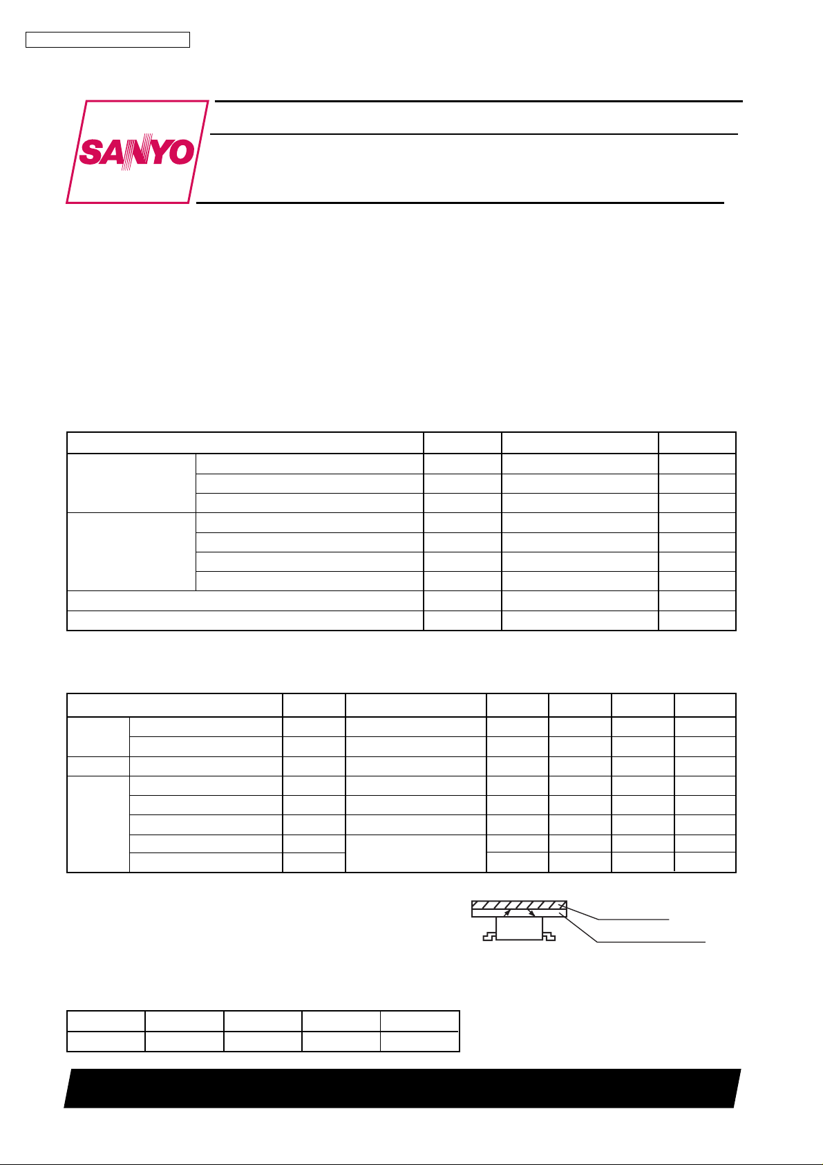
Absolute Maximum Ratings at Ta=25°C, 65%RH (as per JIS C7032)
Parameter Symbol Rating Unit
Input LED
Output
Phototransistor
Forward Current I
Reverse Voltage V
Power Dissipation P
Collector-Emitter Voltage V
Emitter-Collector Voltage V
Collector Curren I
Power Dissipation P
Operating Temperature Topr --20 to +80 °C
Storage Temperature Tstg --30 to +100 °C
F
R
D
CEO
ECO
C
C
Infrared LED
SPI-336-99-T1
50 mA
5V
70 mW
20 V
5V
20 mA
70 mW
Electro-Optical Characteristics at Ta=25°C, 65%RH
Parameter Symbol Condition Min. Typ. Max. Unit
Input
Output Dark Current I
Forward Voltage V
Reverse Current I
CEO
Collector Output I
Coupled
Leakage Current I
Collector Emitter VCE(sat) IF=10mA, IC=50µA -- -- 0.5 V
LEAKIF
Rise Time tr
Fall Time tf
1
*
Location of reflector is shown in Fig. 1.
2
*
No reflector
3
*
Table of Classification of Collector Output
Class A B C D
Ic (µA) 1100 to 450 600 to 260 350 to 150 200 to 80
IF=10mA 1.0 1.2 1.6 V
F
VR= 5 V -- -- 1 0 µ A
R
IF=0mA, VCE=10V -- -- 200 nA
IF=10mA, VCE=5V
C
=10mA, VCE=5V
VCC=5V, RL=100Ω
IC=1mA
1
*
2
*
80 - - 1100 µA
-- -- 1 µA
-- 5 -- µs
-- 5 -- µs
Fig. 1 Location of Reflector
AL V .E. film
Glass plate (t=1mm)
SANYO Electric Co.,Ltd. Semiconductor Company
TOKYO OFFICE Tokyo Bldg., 1-10, 1 Chome, Ueno, Taito-ku, TOKYO, 110-8534 JAPAN
72199 GI, (MI
)
No.6030 1/6
SPI-336-99-T1
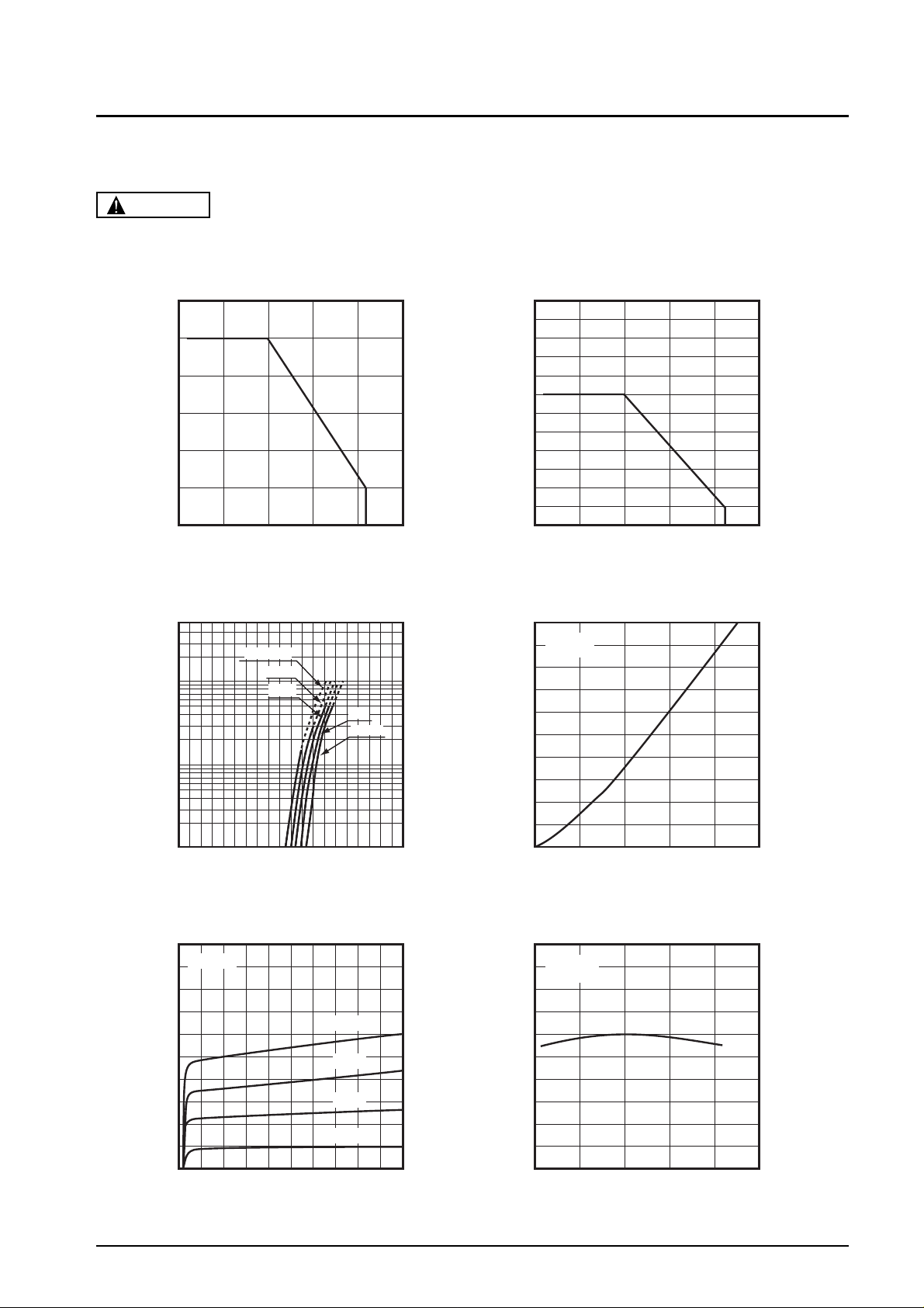
Typical Characteristics
CAUTION
These numerical value show the electrical and optical characteristics of this product, and not assure this contents.
Forward Current vs. Ambient Temperature
60
50
(mA)Collector Current I
40
F
30
20
Forward Current I
10
0
--25 0 25 50 75 100
Ambient Temperature Ta (°C)
Forward Current vs. Forward Voltage
500
Ta=75°C
50°C
25°C
0°C
--25°C
(mA)
F
100
50
Power Dissipation vs. Ambient Temperature
(Rating) (Rating)
120
100
80
60
40
Power Dissipation P (mW)Relative Collector Current (%)
20
0
--25 0 25 50 75 100
Ambient Temperature Ta (°C)
Collector vs. Forward Current
500
V
=5V
CE
Ta=25°C
400
(µA)
C
300
10
Forward Current I
5
1
0 0.5 1 1.5 2
Forward Voltage VF (V)
Collector Current vs. Collector-emitter Voltage
1000
Ta=25°C
800
(µA)
C
600
400
200
0
0510
Collector-emitter Voltage VCE (V)
IF=20mA
15mA
10mA
5mA
200
Collector Current I
100
0
048121620
Forward Current IF (mA)
Relative Collector Current vs. Ambient Temperature
140
IF=10mA
VCE=5V
120
100
80
60
40
--25 0 25 50 75 100
Ambient Temperature Ta (°C)
No.6030 2/6
 Loading...