


OPERATING
INSTRUCTIONS


1. Introduction
g
1. Typographical conventions
2. Safety rules
2. System installation
1. Preliminary operations
1. Opening the package
2. Checking the markings
3. Switching on and off
1. Switching on
2. Switching off
2. Connectors and cables
1. Video cables
2. Keyboard lines
3. Direct Telemetry control
4. DVR and direct/coax Telemetry control
5. Aux Line
6. Personal Computer and Serial Printer Cable
7. BNC for the Alarm Reset
8. Relay and alarm connectors
1. Electrical specifications of the alarms
2. Electrical specifications for the relays
3. Jumpers and DIP
1. Opening the matrix
2. Dip Switch Configuration
1. System configuration and baud rate
2. Restoring the settings
3. Updating the firmware
4. Maintenance
3. Setup
1.
1. Notes regarding the menu system
2. Matrix Setup
3. Setup by On Screen Menu
2. Entering Program Mode
1. DCT / Keyboard
3. Setup Parameters
1. Video system
1. Removing Texts and Masks
2. Simplify Menu
1. Day and Night Periods
3. External Contacts
4. Date
1. Weekdays
2. Single day Festivities
3. Holidays Periods
5. Time
1. Daylight Saving Time
6. Enablin
the keyboards
Page 1 of 33 MNYASM328S_0648

7. Control Monitor
1. Messages on the Control Monitor
2. Excluding video inputs
8. Cameras ID Texts
9. Cyclic sequences
1. Defining and modifying the cyclic sequences
2. Allocating cyclic sequences
1. Auto
10. Alarms
1. Contact Alarms
2. Aux Command Alarms
3. ID text
4. Reset modes
5. Enabling the alarm contact
6. Effects on the monitors
7. Action on receivers
8. Action on relays
9. Buzzer
11. Image Masking
1. Changing the masking
1. Definition of a mask
4. Composite systems
1. 1 Matrix and 1 Slave
2. 1 Matrix and 2 Slaves
5. Event log
1. List of event messages
2. Baud rate and data format
4. Technical specifications
-return time
The manufacturer declines all responsibility for any damage caused by an improper
use of the appliances mentioned in this manual; furthermore, the manufacturer
reserves the right to modify its contents without any prior notice. The
documentation contained in this manual has been collected with great care: the
manufacturer, however, cannot take any liability for its use. The same thing can be
said for any person or company involved in the creation and production of this
manual.
Page 2 of 33 MNYASM328S_0648
Introduction
b
Typographical conventions
This instruction manual makes use of different graphics symbols:
Hazard of electric shock
: unplug the power supply before proceeding with
any operation, unless specified otherwise.
Important
: please read the procedure or information given, and when
applicable perform the operations as instructed. Failure to carry out the procedure
correctly may cause faulty operation of the system or even damage it.
Notes
: we recommend reading the notes to fully understand the system
operations.
Safety rules
The SM328S video matrix complies with current legislation and standards
regarding electrical safety, electromagnetic compatibility and general requirements
in force at the time of publication of this manual. Nevertheless, in order to ensure
the users' safety (installer technician and operator) we hereby specify the following
advice for working as safely as possible:
z
Only authorised, skilled technical personnel should be allowed to install the
appliance (and the whole system of which it forms part)
z
Never open the appliance, unless required by specific procedures described in
this manual.
z
Connect the appliances to a power supply that corresponds with their
respective identification labels
z
For technical services refer only and exclusively to authorised technical
personnel.
z
Do not extract the plug by pulling on the cable.
z
Before moving or carrying out technical work on the appliance, disconnect the
power supply jack: the appliance is to be considered OFF only when the power
supply jack is disconnected and the connection cables to other devices have
een removed.
Page 3 of 33 MNYASM328S_0648

z
Do not use extension cables with signs of wear or ageing, since they could
expose the user to serious safety hazards.
z
Do not allow any liquid to wet the appliance and do not touch it with wet
hands when in operation.
z
Do not leave the appliance exposed to adverse weather conditions.
z
Do not use the appliance in the presence of inflammable substances.
z
Make sure the appliance is always placed on a sufficiently solid broad base.
Tampering with the appliance will invalidate the guarantee.
Keep this manual carefully for future consultation.
Warning: this is a Class A product. In a domestic environment this product
may cause radio interference in which case the user may be required to take
adequate measures.
System installation
Preliminary operations
Opening the package
When the product is delivered make sure the package is intact and has no obvious
signs of dropping, scrapes or scratches. If the package is damaged or if there is
something missing from the following list, contact the supplier immediately.
Material supplied with the matrix should be as follows:
z
1 programmable SM328S video matrix
z
1 user's manual
z
1 wide range power supply, IN 100-240VAC 50/60Hz, OUT 12VDC,
including cables
z
2 DB25 connectors complete with shell
z
1 serial 9-pin cable
Checking the markings
The base of the matrix has a label that complies with CE markings, containing:
Page 4 of 33 MNYASM328S_0648

z
Product identification code
z
Power supply voltage (Volts)
z
Frequency (Hz)
z
Maximum consumption (Watts)
Before proceeding with the installation, examine the marking labels to make sure
the supplied material corresponds with the required specifications. Do not, for any
reason, make changes or connections unless indicated by this manual: using
unsuitable equipment may constitute a serious safety hazard for people and for the
system.
Switching on and off
Before powering the appliance:
z
Examine the marking labels to make sure the supplied material corresponds
with the required specifications.
z
Make sure the matrix and other components in the system are closed up
properly so that the direct contact with operating devices is impossible, except
for the installation procedure otherwise required: in this case proceed with
great care, following the instructions given in this manual.
z
the matrix and the other parts of the system should rest on a large solid base.
z
The power supply and connecting cables should not hamper the installer
technician and operators when carrying out normal operations.
z
Make sure the power outlet and extension cables, if any, are sufficient for the
power load required by the system.
If in doubt, always consider the system on.
Switching on
Plug the power supply into the power outlet and connect the corresponding
jack to the matrix connector labelled 12VDC. Turn the front switch to the ON (I)
position. The LED on the front of the matrix should light up.
Switching off
Turn the front switch to the OFF (O) position.
Page 5 of 33 MNYASM328S_0648

Connectors and cables
p
Video cables
Use an RG 59 coaxial cable or equivalent. Over large distances we advise using a
video transmission system via twisted pair.
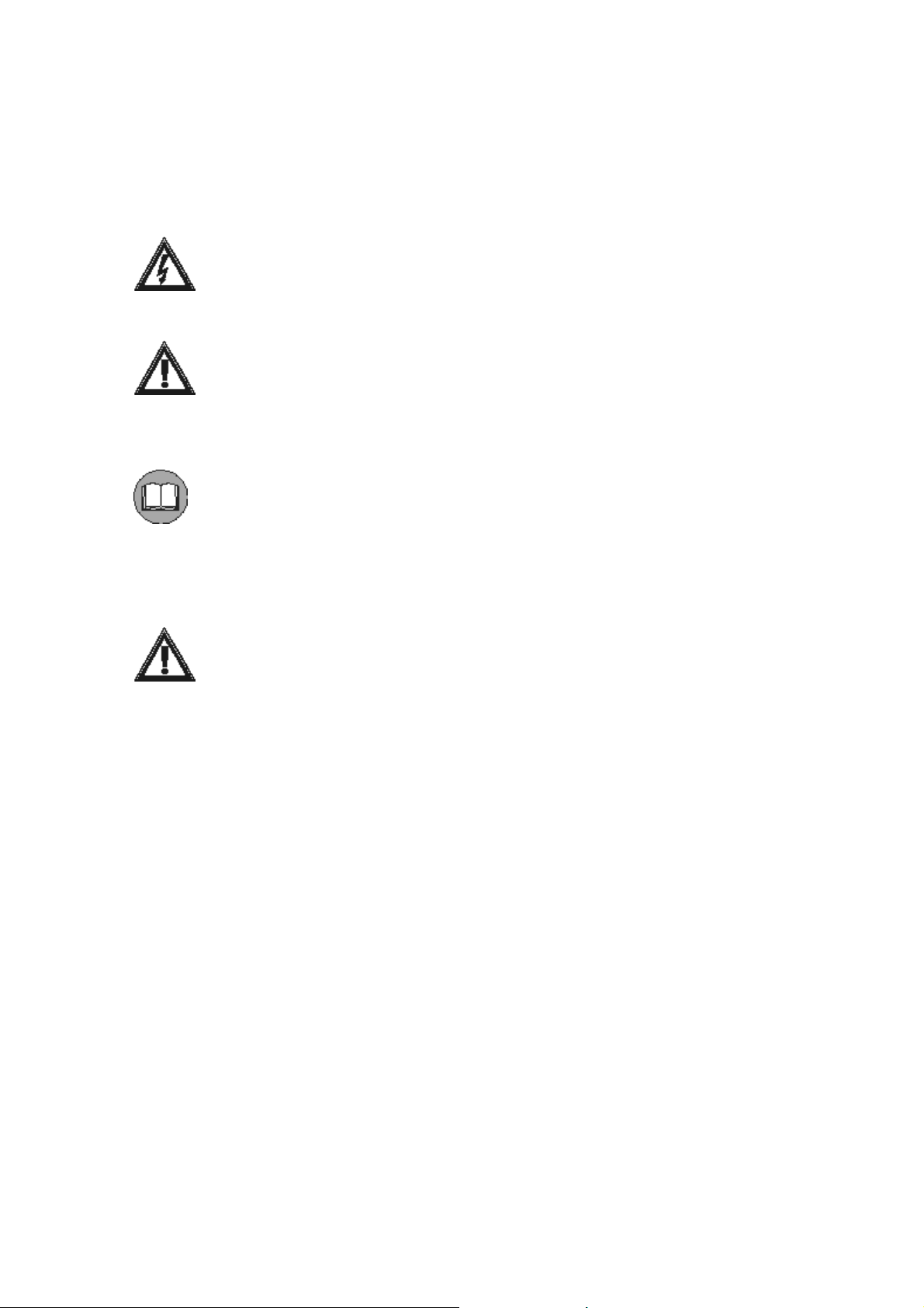
Keyboard lines
Keyboards can only be connected
Keyboards
cannot be connected
on a single
line to a Single or Master matrix.
to Slave matrixes.
The matrix has four RS485 lines for the keyboards connection but only either
number 1 or number 2 can be used (not at the same time):
z
Line 1 is
not loaded (un-terminated)
: use this line when the matrix is not at the
end of a RS485 line (in a real system this is the most frequent case.)
z
Line 2 is
loaded (terminated)
: use this line when the matrix is at the end of a
RS485 line (i.e. during tests with a direct connection between keyboard and
single matrix.)
z
Lines 3 and 4 are reserved for future use and
cannot be used
.
It is possible to connect a keyboard directly to the matrix using a phone cable (1.5m)
or using a long-distance cable up to 1200m: use RJ jack shunt boxes and a nonshielded twisted
air with minimum diameter 0.6 mm (sect.0.22 mm² AWG 24):
Page 6 of 33 MNYASM328S_0648
Keyboard Tx Matrix Rx
RS485A white RS485A blue
RS485B yellow RS485B black
Page 7 of 33 MNYASM328S_0648
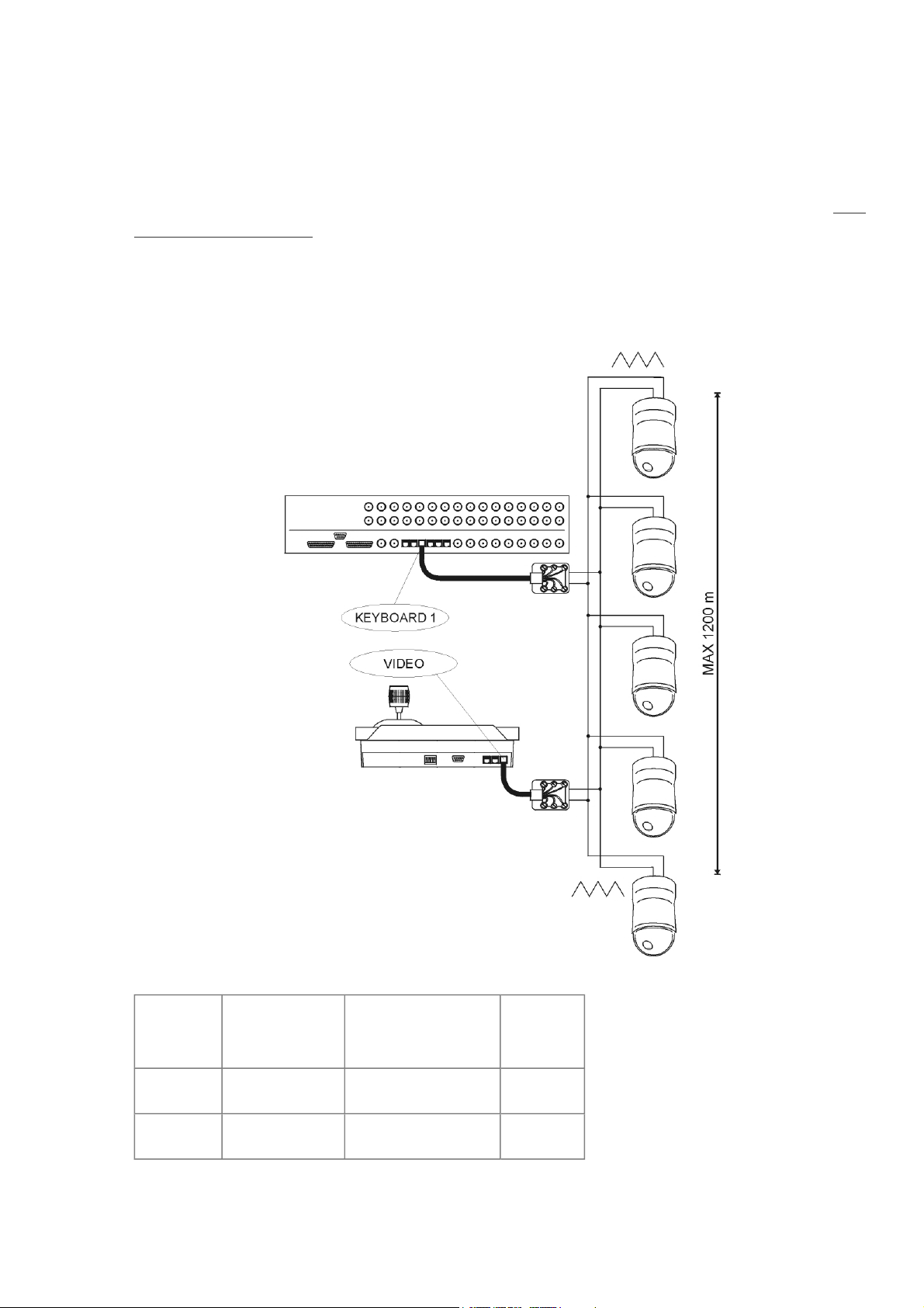
Direct Telemetry control
The matrix can be configured to position telemetry devices (domes) on alarm using
SSP communication protocol.
Please set the dome baudrate at the value set for keyboards communication (cfr. Dip
switch configuration).
Using an RJ jack shunt box connect the dome to the proper RS485A and RS485B
lines:
Poles Keyboards
RS485A white blue line A
RS485B yellow black line B
Single Matrix
Domes
Master Matrix
Page 8 of 33 MNYASM328S_0648
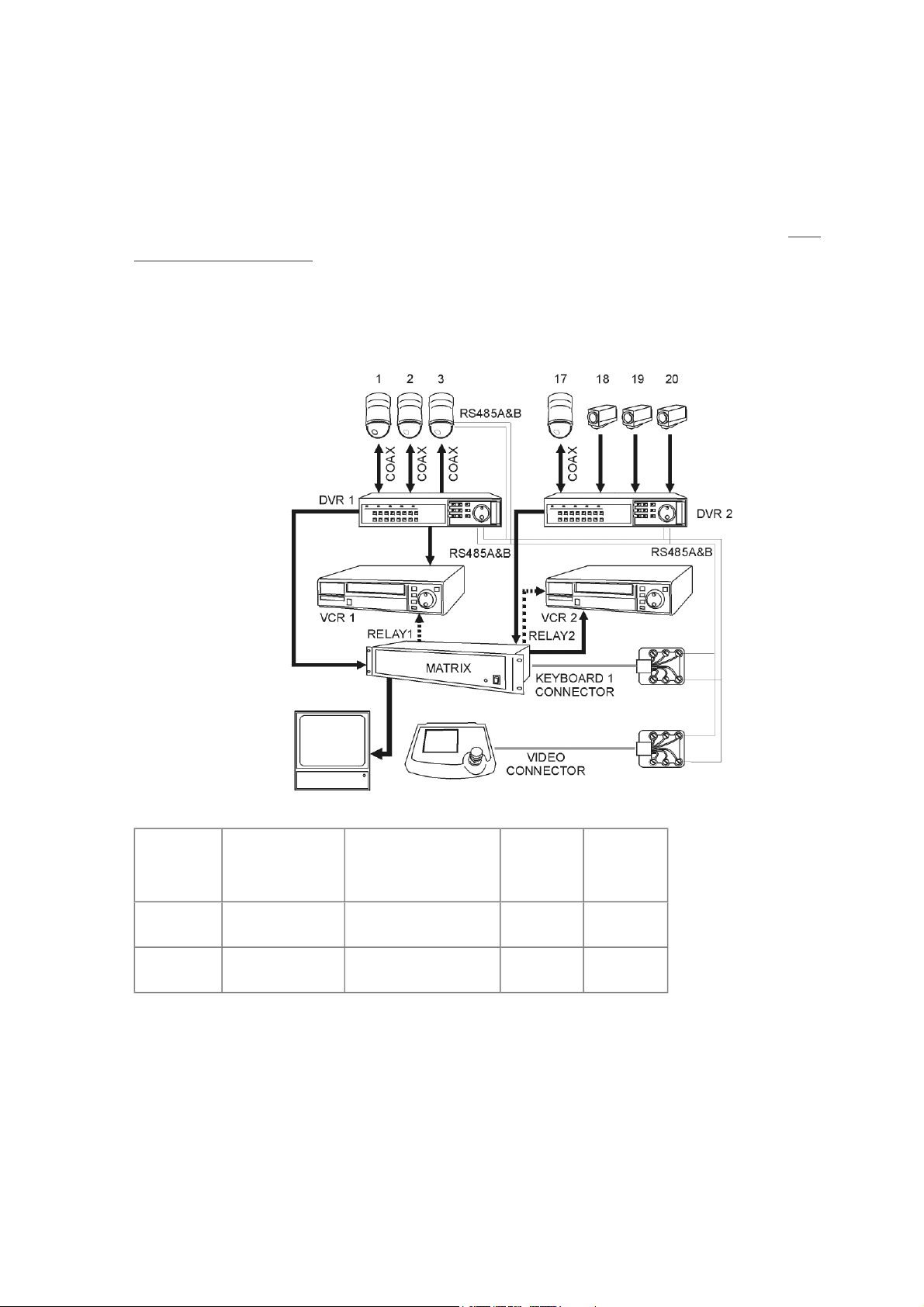
DVR and direct/coax Telemetry control
g
Keyboards can control MUX/DVRs and Telemetry devices (domes) using SSP
communication protocol. Optionally Telemetry devices can be controlled by COAX
through the MUX/DVRs when this function is provided by the MUX/DVR device.
Please set the baudrates at the value set for keyboards communication (cfr. Dip
switch configuration).
Using RJ jack shunt boxes connect the objects to the proper RS485A and RS485B
lines:
Single Matrix
DVRs
Poles Keyboards
Matrix Master
MUXes
RS485A white blue red line A
RS485B yellow black green line B
Aux Line
The matrix is provided with 2 Aux lines:
z
Aux A is used to control optional auxiliary Slave matrixes.
z
Aux B is reserved for future use.
In the case of Sin
le Matrix configuration; Aux A is not used.
Domes
Page 9 of 33 MNYASM328S_0648
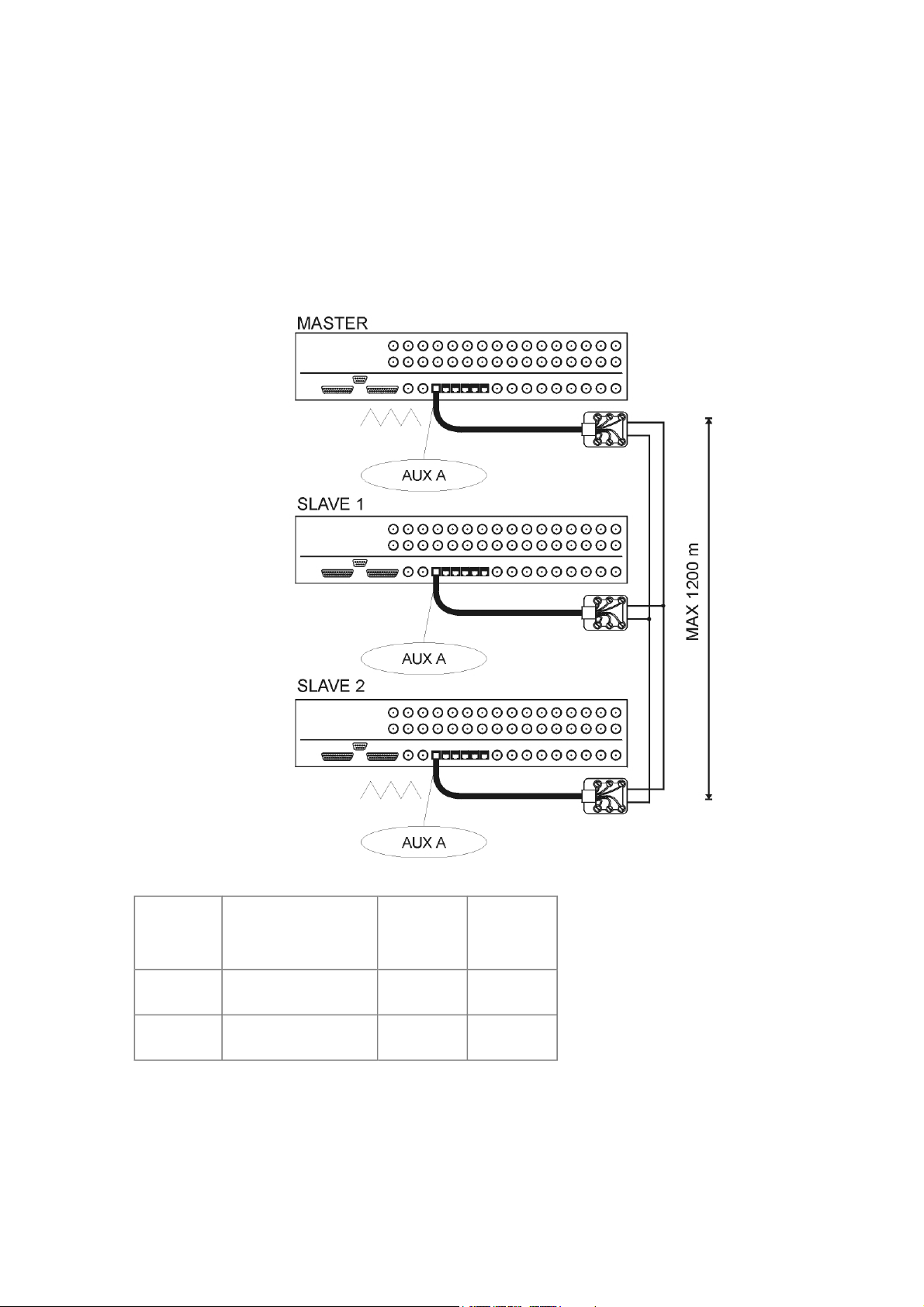
Don't connect any other device on the Aux A line.
To comply with the standard, the RS485 communication lines must be terminated at
the ends to prevent signal reflection. On the Aux A auxiliary communication line
the load can be inserted (jumper AUX_A in LOAD position) or excluded (jumper
AUX_A in NO position). Please insert the load only for the matrixes at the end of
the line.
To connect the Matrixes please use this cable:
Master Matrix
Aux A
RS485A white white white
RS485B yellow yellow yellow
Slave 1
Aux A
Slave 2
Aux A
Personal Computer and Serial Printer Cable
Connect the personal computer or serial printer using a standard complete
male/female 9-pin serial cable (serial extension).
Page 10 of 33 MNYASM328S_0648
 Loading...