

Page 1
Ordering number : EN6225
SLP-4118B-51-T1
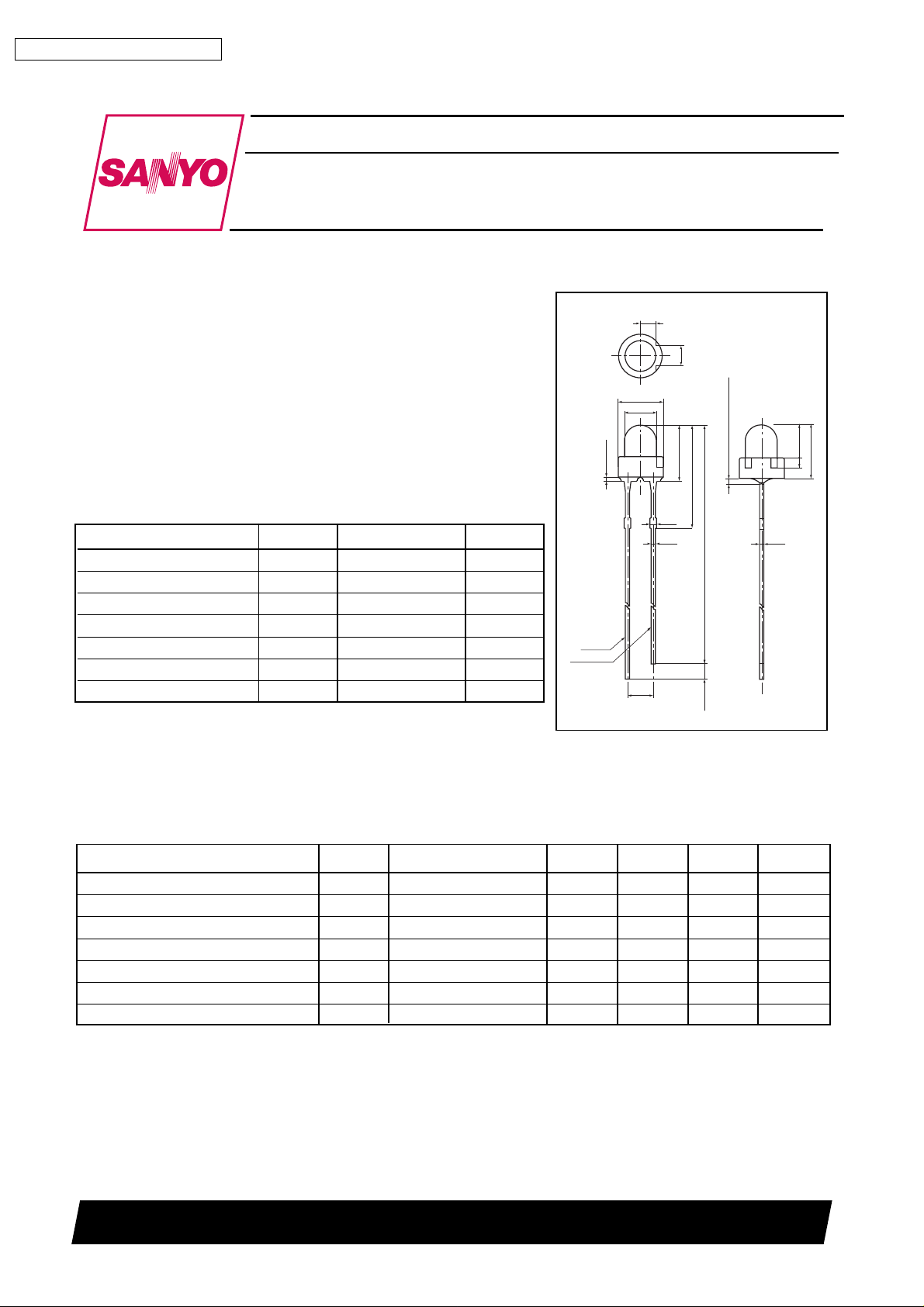
ø3.1mm yellow contact type taping lamp
Features
• GaAsP yellow LED
• 3.1mmø, round top type lamp
• Diffused yellow resin package type
• High luminous intensity, high reliability and long life
• SLP-4118B-51 taping type for an antomatic use
• The insertion which made it stick to PCB is possible
• Application : for the general public welfare
Absolute Maximum Ratings at Ta=25°C (as per JIS C 7032)
Parameter Symbol Rating Unit
1
Forward Current
Pulse Forward Current
Reverse Voltage V
Power Dissipation P
Operating Temperature Topr --25 to +80 °C
Storage Temperature Tstg --30 to +85 °C
Soldering T emperature
1
*
See forward current derating
2
*
Pulse width = Max. 10ms Duty ratio = Max. 1 / 10
3
*
Max. 5sec., Lead soldering condition : Min. 1.6mm from case (used 1.6mmt’s PCB)
*
2
*
3
*
I
F
I
FP
R
D
25 mA
100 mA
3V
70 mW
T sol 260 °C
Cathode
Infrared LED
SLP-4118B-51-T1
Anode
ø4.4
ø3.1
0.8 max
1.55
2.5
Note : Material -- lron
Lead center off : ± 0.4
2
Unit : mm
5.5 ± 0.5
10.2 ± 0.5
0.5
0.4
29.5 ± 1
(1.5)
Coating -- Solder
2 max (not soldered)
0.4
3.2
1
5.2
Electrical / Optical Characteristics at Ta=25°C
Parameter Symbol Conditions Min Typ Max Unit
Foward Voltage V
Reverse Current I
4
Luminous Intensity
*
Peak W ave length λ
I
IF = 20mA 1.7 2.1 2.8 V
F
VR = 3V -- -- 10 µA
R
IF = 20mA 8 17 -- mcd
V
IF = 20mA 575 585 595 nm
P
Line Half Width ∆λ IF = 20mA -- 40 -- nm
Capacitance C
VO = 0 • F = 1MHz -- 40 -- pF
O
Response Time t -- -- 90 -- ns
4
*
Luminous Intensity is measured by J-16 (SONY TEKTRONIX) of which our office possess.
Note
Use a unit as one box.
SANYO Electric Co.,Ltd. Semiconductor Company
TOKYO OFFICE Tokyo Bldg., 1-10, 1 Chome, Ueno, Taito-ku, TOKYO, 110-8534 JAPAN
81099 GI, (MI
)
No.6225 1/6
Page 2

SLP-4118B-51-T1
Typical Characteristics
CAUTION
These shows the electrical and optical characteristics of this products, and not assure this dispersive contents.
Forward Current vs. Forward Voltage
30
20
10
5
3
Forward Current (mA)
2
1
1.6 1.7 1.8 1.9 2.0 2.1 2.2 2.3 2.4
Forward Voltage (V)
Intensity vs. Current
10
5
2
1
0.5
Relative Intensity
0.2
Intensity vs. Temperature (IF : constant)
1.5
1.0
Relative Intensity
0.5
--40 --20 0 20 40 60 80 100
Temperature (°C)
Spectrum
1.0
0.5
Relative Intensity
0.1
1 2 5 10 20 50 100 200 500 550 600 650 700
Forward Current (mA)
Forward Current Derating (Abusolute Maximum Rating)
35
30
25
20
15
10
Forward Current (mA)
5
0
010 3020 40 50 60 70 80 90 100
Temperature (°C)
50°
60°
80°
90°
70°
40°
0
Wave Length (nm)
Directivity
0°
30°
20°
10°
1.0
0.5
0.1
10°
20°
30°
40°
50°
60°
70°
80°
90°
No.6225 2/6
Page 3

SLP-4118B-51-T1
P
øD P2
5.2±0.2
5.5±0.5
P1
L1
W1
W0 W2
W
øD0
Anode Cathode
t
F
P0F'
d
∆S
∆h
H
Adhesive tape
Pasteboard
(Unit : mm)
Item Sym Nominal Tolerance Note
LED Pitch P 12.7 ±1.0
Sending Hole Pitch P0 12.7 ±0.2 *
Sending Hole Slip Out P1 5.1 ±0.5
Sending Hole Slip Out P2 6.35 ±0.5
Slant of LED Lamp ∆h, ∆S0 ±1.0
Width & Dia. of LED Lamp D 3.1 ±0.2
Interval of Lead d 0.4 ±0.2
Space of Lead F 2.5 ±0.7
Space of Lead F
'
(2.5) -----
Distance from LED Lead H 18.0 ±1.0
Dia.of Sending Hole D0 4.0 ±0.2
Lead Slip Out I Max2.0 ----Width of Pasteboard W 18.0 ±0.5
Width of Adhesive Tape W0 13.0 ±0.5
Sending Hole Slip Out W1 9.0 ±0.5
Adhesive Tape Slip Out W2 0.5-1.5 ----Thickness of Pasteboard t 0.5 ±0.2 **
Cutting Position of Rejected L1 Max11.0 ----*Accumulated pitch error : ±1 / 20 pitch **Included thickness of Adhesive tape
No.6225 3/6
Page 4

SLP-4118B-51-T1
1. General Description
These items are applide to taping type LED lamps for automatic use.
2. Taping Specification
Appearance and dimensions. (Refer to the supplementary drawing)
3. Notes
(1)The polarity of LED lamp should be reqularly oriented to one direction.
(2)Sequential cracks in a taped unit shall be 3 pcs. max.
W
Adhesive tape
Pasteboard
(3)Peeling
Adhesive strength of tape peeling in the vertical direction against the taped surface should be more than 300g.
(See below)
(4)Tape conjunction method
1 In the case of Tape pasteboard cutting
• Scotch tape is applied to connect or fix between tapes from the back side of the pasteboard.
Forward direction
Adhesive tape
Pasteboard
approx. 20mm
Scotch tape
• Max. tickness of the tape should be less than 1.1mm.
2 How to fix disconnected tape
fixed by adhesive tape
P0 P0
1max
• Methode by adhesive tape : Stick over fixing each adge.
Note : Taping pitch (P0) should be placed properly. In the case of applying sticking way, the location is to be voluntary.
Sewing Machine Stitch
4. Packaging
55max
(1)The quantity is indicated on a packing case.
(2)Packaging appearance and dimensions. (See right)
320max
1 Winding path will be emloyed as a packing method.
340max
m / m
2 When LED lamps are taken out of a packing case, follow the LED polarity configuration. (See below)
3 Packaging display
No.6225 4/6
Page 5

SLP-4118B-51-T1
PRECAUTIONS
< Automatic stick inserting, straight taping type >
(1) Bending a lead should avoid not to cause chip deterioration or so. When bending is necessary, care must be taken
considering the following points :
q Bending a lead must be done before soldering.
w A lead must be bent at intervals of 1.6mm from the edge of the regin part.
e Do not bend the same portion of lead more than twice.
(2) Setting a product by a tool such as holder should avoid. When necessary , no stress should be applied to the regin part and
lead by sufficient considerations on dimension tolerance, thermal expansion, thermal contraction of holder , product and
circuit board.
(3) The hole pitch of a circuit board must fit to its lead pitch.
(4) When soldering, care must be taken considering the following points :
q Do not heat a product under any stress (ex. : twist) to leads.
w Do not heat (by soldering, for example) a product in the states of being forced to the resin part.
(5) Do not use the flux containing chlorine (max. 0.2wt%) which may cause corrosion of lead and washing is preferable.
When washing is necessary, avoid washing the whole product and wash only the needed part under the following
conditions.
• Chemicals : Methyl alchole.
• Temperature : 45°C max.
• Time : 30sec. max.
Note :Recommendatory conditions of automatic insertion and reflow (adhesive hardening process) taping lamp is
automatically inserted and the chip portion is attached to the back side. When using taping lamp in the process
through reflow furnace, follow the initial conditions in the new process to prevent gold wire breaking in process
of LED manufacturing and to secure high reliability.
<Cl inch angle>
(1)Setting of automatic insertion machine
q Speed : not more than 1.0sec. / p.
w Chuch pressure : not more than 3.0kg / cm2.
e Head pressure : not more than 1.0kg / cm2.
r Clinch angle : bendingangle.
--Anode side within 15°
--Cathode side within 45°
15° min.
Anode
45° min.
Cathode
t Cutter : To avoid tearing lead off, use of sharp and hard cutter withstanding 1million time in preferable.
(2)Pre-hardening furnace
q T emperature : When hardening chips by adhesive at 150°C(120sec), set the surface temperature of LED regin part to
120°C or less ; even influence of increase in temperature to the back side of LED part is low.
(Temperature of 130°C is about the line that causes deformation (heat deflection temperature) of regin used in
standard LED. If temperature is increased while stress is on lead, even small, resin is softened and the life of held
lead is lowered. This may cause gold wire breaking due to moving lead.)
(3)Solder dipping
q Temperature of soldering bath : 260°C or less.
w Dipping time : within 5sec.
e Lead soldering condition : min 1.6mm from case.
No.6225 5/6
Page 6

SLP-4118B-51-T1
CAUTION
1. No products described or contained herein are intended for use in surgical implants, life-support systems,
aerospace equipment, nuclear power control systems, vehicles, disaster / crime-prevention equipment or
the like, and the failure of which may directly or indirectly cause injury, death or property loss.
2. Anyone purchasing any products described or contained herein for an above-mentioned use shall:
1) Accept full responsibility and indemnify and defend SANYO ELECTRIC CO.,LTD., it’s affiliates,
subsidiaries and distributors or any of their officers and employees, jointly and severally, against any
and all claims and litigation and all damages, costs and expenses associated with such use.
2) Not impose any responsibility for any fault or negligence which may be cited in any such claim or
litigation on SANYO ELECTRIC CO., LTD., it’s affiliates, subsidiaries and distributors or any of
their officers and employees jointly or severally.
3. Information (including circuit diagrams and circuit parameters) disclosed herein is for example only; it is not
guaranteed for mass production, SANYO believes the information disclosed herein is accurate and reliable,
but no guarantees are made or implied regarding it’s use or any infringements of intellectual property rights
or other rights of third parties.
Precautionary instructions in handling gallium arsenic products
Special precautions must be taken in handling this product because it contains, gallium arsenic, which is
designated as a toxic substance by law. Be sure to adhere strictly to all applicable laws and regulations
enacted for this substance, particularly when it comes to disposal.
Manufactured by ; Tottori SANYO Electric Co., Ltd.
LED Division
5-318, Tachikawa-cho, Tottori City, 680-8634 Japan
TEL: +81-857-21-2137 FAX: +81-857-21-2161
PS
No.6225 6/6
 Loading...