

Page 1
Gas Driven VRF
GAS DRIVEN VRF
ELECTRIC VRF
COMMERCIAL SPLIT SYSTEMS
ROOM AIR CONDITIONERS
HEATING SOLUTIONS
M Series
SANYO Air Conditioners. The natural choice.
Page 2
2
Rating Conditions: Cooling Indoor 27°C DB 19°C WB Outdoor 35°C DB 24°C WB Heating Indoor 20°C DB Outdoor 7°C DB 6°C WB
3
Rating Conditions: Cooling Indoor 27°C DB 19°C WB Outdoor 35°C DB 24°C WB Heating Indoor 20°C DB Outdoor 7°C DB 6°C WB
SANYO GHP - the natural choice
Discharge of heat
absorbed from the
inside of the room
by liquefaction of
refrigerant.
Heat Heat
Refrigerant gas
Refrigerant
liquid
Refrigerant liquid
Outdoor unit
Outdoor unit
Warm air
Warm air
Cold air
Cold air
Compressor
Gas engine
Compressor
Gas engine
Absorption of heat
from the outside air
by evaporation of
refrigerant.
Refrigerant
gas
Engine waste heat
Hot water
function
Absorption of heat from the room by
liquefaction of refrigerant.
Discharge of heat generated by
condensation of refrigerant.
Gas Heat Pump M Series - the perfect solution
when you’re short of power
SANYO benets
What is a GHP?
The application principle of Variable Refrigerant Flow
(VRF) systems for projects with multiple indoor unit is now
very much an integral element of the UK air conditioning
market place.
SANYO has been developing GHP VRF systems since
1980, during which time we have been committed to
delivering ground-breaking technology. As a result, the
commercial range of GHP VRF systems is leading the
industry in the development of ecient and exible
systems, making them the natural choice for commercial
projects, especially for those projects where power
restrictions apply. As you would expect, all of our gas
driven VRF systems have the highest reliability rates in
the industry and a leading customer service programme.
The M Series of gas driven VRF systems oers increased eciency
and performance across the range. Now more powerful than
ever before, it can connect to up to 48 indoor units.
Improvements include increased part load performance,
reduced gas consumption with a Miller-cycle engine and
reduced electrical consumption from using DC fan motors.
• Up to 71kW of cooling from a maximum running capacity of 5
AMPs
• Single phase power supply across the range
• The option of natural gas or LPG as its main power source
• Free hot water! A water heat exchanger to connect to domestic
hot water systems 13-25 HP (Heat Pump only)
• Option of DX or chilled water for indoor heat exchange
• Option to connect to third party Air Handling Units
• Reduced CO
emissions
2
Power supply problems?
If you are short of electrical power, gas heat pump
could be the perfect solution.
High-eciency operation
13-25 HP models are equipped with a high-performance air
exchanger and a newly developed refrigerant heat exchanger
for high-eciency operation, making them one of the most
energy-ecient solutions on the market.
Lowest nitrogen oxide emissions
The GHP VRF systems have the lowest nitrogen oxide emissions,
66% below the standard. In a pioneering development, the
SANYO GHP features a brand new lean-burn combustion
system that utilises air fuel ratio feedback control to reduce NOx
emissions to an all-time low.
Excellent economy
The SANYO GHP provides quick and powerful cooling/
heating and increases delivery of heat into the space by the
ecient recovery of heat from the engine cooling water,
which is injected into the refrigerant circuit.
In addition, the use of engine waste heat ensures that our gas
heat pump air conditioner requires no defrost cycle, therefore
providing continuous 100% heating performance in severe
weather conditions with an outside air temperature as low as
-20°C. During cooling mode the rejected heat from the engine is
available for use within a hot water system and can supply up to
25kW of hot water at 75 °C.
High performance
With its advanced heat exchanger design, this new GHP system
oers improved eciency and reduced running costs, which,
coupled with improved engine management systems, have
greatly improved the system COP rating.
New electrical power generator model
The biggest breakthrough in recent GHP technology is the
launch of the ECO G Power, which provides 4.0kW of power.
That’s enough electricity to power 8 computers or other
applications.
A GHP is no dierent in principle, however,
developed by SANYO in 1980 the GHP outdoor unit
is tted with a combustion engine, powered by
Natural gas or LPG, to drive the refrigerant compressor.
Variable capacity is achieved via the engine speed being
altered up and down just as an inverter compressor speed
is controlled in the electric VRF equivalent. The GHP
therefore is an ideal solution where electrical power is at a
premium (or no 3 phase available) however it also boasts
a number of additional benets/functions that are not
available on an electric equivalent
.
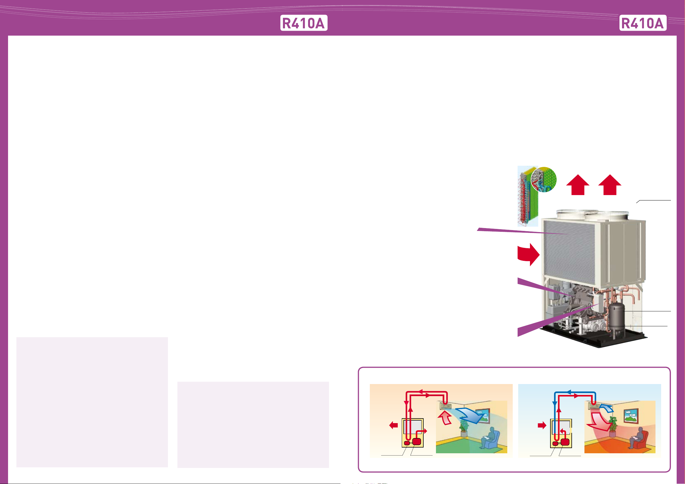
High eciency heat exchanger
The ‘M’ series GHP continues to use a ‘hybrid’ heat exchanger for
improved eciency. By interlacing the refrigerant coil with the
radiator carrying the coolant from the engine, the condensing
capacity and radiator performance is balanced to an optimum
level. This combination ensures the cooling eciency drop in
cold ambient is kept to a minimum, heating performance is
down to -20oc and maintain a high COP.
Higher engine eciency
Air
By utilising a Miler-Cycle engine, the compression stroke is
reduced and therefore pumping losses are minimised. As a
result the expansion volume ratio increases and the eciency
improves.
Miller cycle: This heat cycle has the characteristic that the closing
time for the suction valve in regard to the base engine is late.
As a result, the expansion stroke becomes relatively longer in
comparison to the compression stroke.
Refrigerant heat exchanger
By tting a new plate heat exchanger the engine waste heat
is recovered eciently and reused to improve performance. In
addition a proportionate control 3 way change over valve is used
for control of the engine cooling water to increase eciency in
heating operation
How a GHP works - High performance and low operating costs by using gas fuel
Exhaust
Fan
Accumulator
Compressor
• Runs on gas and just needs single phase supply.
• Enables the building’s electrical power supply to be
used for other critical electrical demands.
• Reduces capital cost to upgrade power substations
to run heating and cooling systems.
• Reduces power loadings within a building especially
• Electricity supply freed up for other uses such as IT
during peak periods.
servers, commercial refrigeration, manufacturing,
lighting etc.
GHP features at a glance
• Power generation of up to 4kW on ECO G Power version
•
Up to 25kW hot water generation on all 2 pipe heat pump
versions
• Chiller module available for water based solutions
• 100% heating performance even at -200c ambient
• 180% indoor connectability (Single heat pump module)
• Single phase power required through the range
Cooling Heating
Page 3
4
Rating Conditions: Cooling Indoor 27°C DB 19°C WB Outdoor 35°C DB 24°C WB Heating Indoor 20°C DB Outdoor 7°C DB 6°C WB
5
Rating Conditions: Cooling Indoor 27°C DB 19°C WB Outdoor 35°C DB 24°C WB Heating Indoor 20°C DB Outdoor 7°C DB 6°C WB
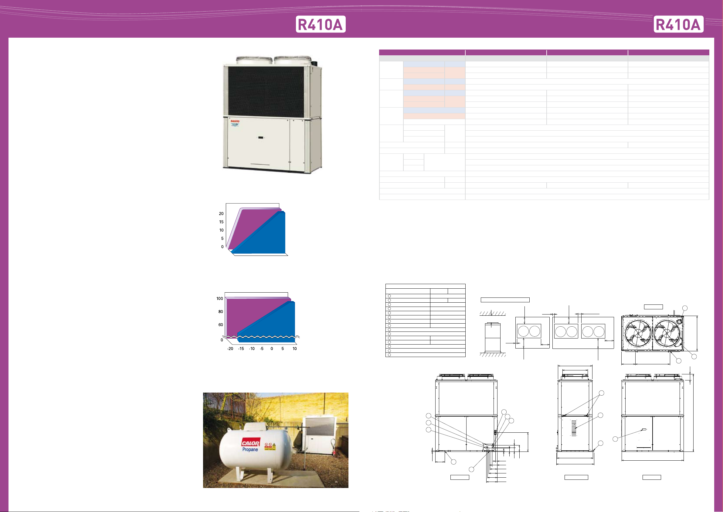
Still the only heat recovery (3 way) GHP system in
Comparison of the start times for heating operation
Room temperature (˚C )
Gas heat pump
Electric heat pump
Time axis (in case of the same load) Outside air temperature (˚C)
Electric heat pump
Gas heat pump
Comparison of heating capacity
Heating capacity (% )
Electric heat pump
Gas heat pump
Comparison of heating capacity
Heating capacity (% )
Rear View Front View
Left Side View
at least 2000
Service Clearances for installation
(Units: mm)
Rear
(refrigerant tubing)
Rear
(refrigerant tubing)
at least
600
at least
600
at least
1000
at least
1000
at least
100
at least
100
at least
100
at least
350
at least
350
Front View Front View
(Single-unit installation)
(Multi-unit series installation)
Suction refrigerant pipe
ø28.58
ø22.22
Size (mm)
Model Type 150
190 240
ø25.4
ø19.05
ø28
ø28
G: R3/4
ø20
4 - ø20
4 - ø24
OD: ø25 Length: 200
1
Discharge refrigerant pipe
2
Liquid refrigerant pipe
3
Exhaust gas drain hose
4
Inter-unit cable port
5
Electrical power supply port
6
Fuel gas port
7
Condensation drain opening
8
Rain and condensation outlet
9
Engine exhaust outlet
10
Suspension holes
11
Anchor holes
12
Segmented display
13
Coolant intake (top)
14
Vent
15
Top View
1800 (external)
2248 (+30)
(181)
400
1014
(anchor pitch)
1000
(anchor pitch)
10
14
12
13
1030
(suspension holes)
1000 (external)
ø736
1060
(frame width)
9
15
11
27
54
147
22
99
108
181
57
207
242
279
312
555
271
7
6
5
4
3
1
2
8
Europe.
The new M Series ECO G 3 Way oers even more
performance and outstanding features when you need
simultaneous heating and cooling. Now with increased
capacities available from 16HP to 25HP, SANYO oers the
greatest choice and exibility to solve any power problem or
site requirement.
• Simultaneous heating and cooling for total control
• Reduced gas consumption by Miller-cycle engine
• Reduced electrical power consumption by using DC motors
• New lightweight design by use of aluminium engine block
reduces weight by 110kg
• Part load eciencies increased
• Connectability increased to up to 36 indoor units
• Now available in 16, 20 and 25HP
• 200m maximum allowable piping length (L1) (equivalent - refer
to technical manual)
ECO G 3 Way Outdoor Unit SpecicationsECO G 3 Way Heat Recovery VRF System
HP 16 20 25
Model SGP-EZ150M2G2 SGP-EZ190M2G2 SGP-EZ240M2G2
Capacity
Electricity
Gas
COP
Size
Weight kg 845 875
Starter amperes A 30
Piping
connection
Pipe fuel gas R3/4 (bolt thread)
Pipe exhaust drain mm ø 25 rubber hose
Operation sound dB(A) 57 58 62
Indoor/outdoor capacity ratio 50-180% *1
Number of indoor connections 36
* 1: Low temp condition: Outdoor temperature 2 C˚.
Condenser actual pipe connec tions may vary from above pipe connections shown, please refer to technical manuals for full details.
Please refer to tube sizing charts for pipe selections and pipe length parameters.
Cooling kW 45.0 56.0 71.0
Heating STD
Heating Low temp* 53.0 67.0 75.0
Cooling kW 1.35
Heating kW 1.01 1.54
Cooling kW 31.6 38.3 60.9
Heating STD
Heating LOW 47.3 56.4 64.9
Cooling 1.37 1.41 1.14
Heating 1.35 1.43 1.34
AVE 1.36 1.42 1.24
Gas
Discharge 7/8 (22.22)
Inches (mm)
Liquid 3/4 (19.05)
kW
kW
Height
mm
Width 1,800
Depth 1,000 (+60)
50.0 63.0 80.0
36.1 43.0 58.0
2,248
1 1/8 (28.58)
• Diversity ratio 50% - 130%
• Extended pipe runs (total 500m)
• Silent mode oers a further 2dB(A) reduction
• 10,000 run hours between engine service intervals (equivalent
to one maintenance every 3.2 years*)
• Full heating capacity down to -20°C
• No defrost cycle
* Assuming 3120 running hrs per year - 12 hrs x 5 days x 52 week s
ECO G 3 Way is ideal for the following types of
application:
• Oce buildings with a diverse range of room temperatures
due to diering load proles.
• Buildings with computer rooms requiring year round cooling.
Additional parts
By taking its power supply from the nearest indoor unit, the
SANYO solenoid valve (change-over box) does not require any
additional fused spur and at only 150mm high can be easily
installed within a 200mm void space.
LPG option
The option of using LPG as a power supply increases exibility
and avoids the problems of potential site restrictions in the
future. The purer fuel is also excellent for further reductions
in CO2 emissions - a fact recognised by the government.
Dimensions ECO G 3 Way (16-25HP)
Page 4

6
Rating Conditions: Cooling Indoor 27°C DB 19°C WB Outdoor 35°C DB 24°C WB Heating Indoor 20°C DB Outdoor 7°C DB 6°C WB
7
Rating Conditions: Cooling Indoor 27°C DB 19°C WB Outdoor 35°C DB 24°C WB Heating Indoor 20°C DB Outdoor 7°C DB 6°C WB
ECO G 2 Way Heat Pump VRF System
Rear View Front View
Left Side View
at least 2000
Service Clearances for installation
(Units: mm)
Rear
(refrigerant tubing)
Rear
(refrigerant tubing)
at least
600
at least
600
at least
1000
at least
1000
at least
100
at least
100
at least
100
at least
350
at least
350
Front View Front View
(Single-unit installation)
(Multi-unit series installation)
Gas refrigerant pipe (Gas tube)
ø25.4 ø28.58
ø12.7
Size (mm)
120Model Type 150
190 and 240
ø15.88
ø9.52
ø28
ø28
ø28
G: R3/4
ø20
4 - ø20
4 - ø24
Rp3/4
Rp3/4
OD: ø25 Length: 200
1
Liquid refrigerant pipe (Liquid tube)
2
Refrigerant balance pipe (Balance tube)
3
Exhaust gas drain hose
4
Electrical power supply port
5
Inter-unit cable port
6
Fuel gas port
7
Condensation drain opening
8
Rain and condensation outlet
9
Engine exhaust outlet
10
Suspension holes
11
Anchor holes
12
Segmented display
13
Coolant intake (top)
14
Vent
15
Hot water intake
16
Hot water outlet
17
Cable inlet for interlock and the like
18
Top View
1800
2248
400
1014
(anchor pitch)
1000
(anchor pitch)
10
14
12
12
1040
1000
ø736
1060
9
15
11
27
118 50
55
54
147
207
242
275
312
461
5583999522
555
163
271
3
17
16
7
2
1
4
8
18
6
5
ECO G W-Multi for Heat Pump
Applications
The new and improved M Series heat pump
(2 Way) not only oers improved performance
but also increased exibility. Now available as
multi-systems, many combinations are possible,
from 13HP to 50HP, allowing for more power
and enabling accurate matching of a system building
load. Additional new features include part load engine
management and compressor run hour equalisation.
• Reduced gas consumption by Miller-cycle engine
• Reduced electrical power consumption by using DC motors
• New lightweight design by use of aluminium engine block
reduces weight by 110kg
ECO G 2 Way Outdoor Unit Specications
Dimensions ECO G W-Multi 2 Way
• Part load eciencies increased
• Connectability increased - now up to 48 indoor units
• Multi-systems with combinations from 13HP up to 50HP
• 200m maximum allowable piping length (L1) (equivalent - refer
to technical manual)
• Diversity ratio 50-180%
• Extended pipe runs (total 500m)
• Industry leading sound levels
• Silent mode oers a further 2dB(A) reduction
• Chiller option
- 13HP (25kW cooling - 30kW heating)
- 25HP (56kW cooling - 67kW heating)
• 10,000 run hours between engine service intervals (equivalent
to one maintenance every 3.2 years*)
• Full heating capacity down to -20°C
• No defrost cycle
* Assuming 3120 running hrs per year - 12 hrs x 5 days x 52 weeks
HP 13 16 20 25 26 29 32 33* 36* 40* 45* 50
Model name
Capacity
Electricity
Gas consumption
COP
Max COP (inc hot water) Cooling 1.87 1.85 1.92 1.54 1.87 1.86 1.85 1.90 1.89 1.92 1.69 1.54
Size
Cooling kW 35.50 45.00 56.00 71.00 80.50 90.00 91.50 101.00 112..0 127.00 142.00
Heating STD
Heating Low temp*1 42.50 53.00 67.00 75.00 85.00 95.50 106.00 109.50 120.00 134.00 142.00 150.00
Hot water 12.00 16.00 20.00 25.00 24.00 28.00 32.00 32.00 36.00 40.00 45.00 50.00
Cooling kW 0.85 1.35 1.70 2.20 2.70 2.20 2.70
Heating 1.01 1.54 2.02 2.55 3.08
Cooling kW 24.50 31.60 38.30 60.90 49.00 56.10 63.20 62.80 69.90 76.60 99.20 121.80
Heating STD
Heating LOW 36.80 47.30 56.40 64.90 73.60 84.10 94.60 93.20 103.70 112.80 121.30 129.80
kW
kW
Cooling 1.40 1.37 1.41 1.14 1.40 1.38 1.37 1.41 1.39 1.41 1.25 1.14
Heating 1.37 1.35 1.43 1.34 1.37 1.36 1.35 1.41 1.39 1.43 1.38 1.34
AVE 1.39 1.36 1.42 1.24 1.39 1.37 1.36 1.41 1.39 1.42 1.31 1.24
Height
mm
Width 1,800 1,800 + 100 (min distance) + 1,800 (in a straight installation)
SGP-EW120M2G2W SGP-EW150M2G2W SGP-EW190M2G2W SGP-EW240M2G2W SGP-EW120M2G2W SGP-EW120M2G2W SGP-EW150M2G2W SGP-EW120M2G2W SGP-EW150M2G2W SGP-EW190M2G2W SGP-EW190M2G2W SGP-EW240M2G2W
SGP-EW120M2G2W SGP-EW150M2G2W SGP-EW150M2G2W SGP-EW190M2G2W SGP-EW190M2G2W SGP-EW190M2G2W SGP-EW240M2G2W SGP-EW240M2G2W
40.00 50.00 63.00 80.00 90.00 100.00 103.00 113.00 126.00 143.00 160.00
28.10 36.10 43.00 58.00 56.20 64.20 72.20 71.10 79.10 86.00 101.00 116.00
2,248
Depth 1,000 (+60)
Weight kg 790 820 850 1,580 1,610 1,640 1,670 1,700
Starter amperes (A) 30
Gas
Piping connection
Liquid 1/2 (12.7) 5/8 (15.88) 3/4 (19.05)
Inches (mm)
Balance 3/8 (9.52)
Pipe fuel gas R3/4 (bolt thread)
Pipe exhaust drain ø25 rubber hose
Operation sound dB(A) 57 58 62 60 61 63 65
Indoor/outdoor capacity ratio 50-180 % 50-130 %
Number of indoor connections 32 36 48
* In case of these combinations EGW190M2G2W is able to connect as W-multi instead of EW190M2G2w.
* 1: Low temp condition: Outdoor temperature 2 C˚.
Condenser actual pipe connections may vary from above pipe connections shown, please refer to technical manuals for full details.
Please refer to tube sizing charts for pipe selections and pipe length parameters.
Capacity Hot Water is available when outside ambient air temperature is above 7C˚.
1 1/8 (28.58) 1 3/8 (34.92) 1 5/8 (41.27)
Page 5

8
Rating Conditions: Cooling Indoor 27°C DB 19°C WB Outdoor 35°C DB 24°C WB Heating Indoor 20°C DB Outdoor 7°C DB 6°C WB
9
Rating Conditions: Cooling Indoor 27°C DB 19°C WB Outdoor 35°C DB 24°C WB Heating Indoor 20°C DB Outdoor 7°C DB 6°C WB
ECO G Power - GHP with electricity generation
Service Clearances for installation
Top View
Rear View Front View
Left Side View
at least 2000
(Units: mm)
Rear
(refrigerant tubing)
Rear
(refrigerant tubing)
at least
600
at least
600
at least
1000
at least
1000
22
50
271
54
147
207
242
275
312
461
27
83
99
138
163
178
193
555
at least
100
at least
100
1000 (external)
1800 (external)
1040
(suspension holes)
1100
(frame width)
ø736
at least
100
at least
350
400
(169)
2248 5
1014
(anchor pitch)
1000
(anchor pitch)
at least
350
Front View Front View
(Single-unit installation) (Multi-unit series installation)
Gas refrigerant pipe (Gas tube) ø28.58
Size (mm)
ø15.88
ø9.52
ø28
ø28
ø20
ø28
ø40
G: R3/4
Rp3/4
Rp3/4
OD:
Length:
1
Liquid refrigerant pipe (Liquid tube)
2
Refrigerant balance pipe (Balance tube)
3
Exhaust gas drain hose
4
Electrical power supply port
5
Inter-unit cable port
6
Inverter cable port
7
Inverter cable port
8
Fuel gas port
9
Condensation drain opening
10
Rain and condensation outlet
11
Engine exhaust outlet
12
Suspension holes 4 - ø20
13
Anchor holes 4 - ø24
14
Segment display
15
Coolant intake (top)
16
Vent
17
Hot water intake
18
Hot water outlet
19
12
14 16
9
11
17
13
15
8
3
4
2
10
1
19
18
7
5
6
& hot water supply
NEW 2 way gas driven VRF with electrical
power generator
SANYO’s ECO G Power is a revolution in air
conditioning design. Fitted with a permanent
magnet, non-bearing type generator, it is the rst
VRF system that can supply heating, cooling, hot
water and now also a supply of electrical power.
Each ECO G Power unit has a 4.0kW generator, which
provides enough electricity to power 8 computers or
other applications.
• Innovative technology that reduces CO2 emissions by up to
30%
• Heat pump air conditioning system providing cooling
or heating
• Can provide both electricity and hot water in heating and
cooling mode
• Up to 4kW electricity generated
• Very ecient generator
• Hot water provided when cooling or heating when outside
ambient air temperature is above 7°C
• 22kW hot water generation capacity
• 20HP model provides 56kW cooling or 63kW heating
• Can connect to up to 36 indoor units
• 200m maximum allowable piping length (L1) (equivalent - refer
to technical manual)
• IU/OU capacity ratio 50 - 130%
NEW
High power
engine
Line linkage
inverter
Production of electricity
Generates from 2kW to 4kW depending on air conditioning
load
4.5
4
3.5
3
2.5
2
1.5
1
Production of electricity (kW)
0.5
0
0 10 20 30 40 50 60 70 80 90 100
Air conditioning load (%)
Generate electricity during heating or cooling
operation
Generate electricity and air conditioning (heating or cooling)
at the same time by using remaining engine power. ECO G
Power can generate from 2.3 to 4.0kW electricity at a generation
eciency of more than 40%.
Power generator
• permanent
magnet type
• non-bearing
Double clutch
compressor
HP 20 33 36 40 45
Model
Cooling kW 56.0 91.50 101.00 112.00 127.00
Capacity
Power generater capacity at
rating
Electricity
Gas consumption
COP Air conditioning only
Max COP (Inc generater, hot water)
Cooling
Height
Weight kg 875 1,660 1,685 1,740 1,720
Starter amperes A 30
Pipe
Pipe fuel gas R3/4 (bolt, thread)
Pipe exhaust drain port mm ø25 rubber hose
Operation sound dB(A) 58 61 63
Indoor/outdoor capacity ratio 50-130%
Number of indoor connections* 32 48
Condenser actual pipe connec tions may vary from above pipe connections shown, please refer to technical manuals for full details.
Please refer to tube sizing charts for pipe selections and pipe length parameters.
Capacit y Hot Water is available when outside ambient air temperature is above 7˚C.
Heating STD
Heating Low temp*1 67.0 109.50 120.00 134.00 142.00
Hot water 22.0 34.0 38.0 44.0 47 .00
Cooling kW 1.35 2.20 2.70
Heating kW 1.01 2.02 2.55
Cooling kW 44.0 (38.3)* 68.50 75.60 88.00 104.90
Heating STD
Heating
LOW
Height
Width 1,800 1,800 + 100 (Min distance) + 1,800
Depth 1,000 (+60)
Gas
Liquid 5/8 (15.88) 3/4 (19.05)
Balance 3/8 (9.52)
kW
kW DC 2.5 (Max 4.3)
kW
Cooling 1.33 (1.41)* 1.29 1.23 1.18
Heating 1.34 (1.43)* 1.31 1.30 1.27 1.38
AVE 1.34 (1.42)* 1.30 1.25 1.28
mm
Inches (mm)
SGP-EGW190M2G2W SGP-EW120M2G2W SGP-EW150M2G2W SGP-EGW190M2G2W SGP-EGW190M2G2W
SGP-EGW190M2G2W SGP-EGW190M2G2W SGP-EGW190M2G2W SGP-EW240M2G2W
63.0 103.0 113.00 126.00 143.00
48.7 (43.0)* 76.80 84.80 97.40 101.00
62.1 (56.4)* 98.90 109.40 124.20 121.30
1.78 1.81 1.80 1.78 1.69
2,248
1 1/8 (28.58) 1 3/8 (34.92) 1 5/8 (41.27)
Dimensions ECO G Power
Page 6

System configured at site
Main
Hot Water
Boiler
Hot water inlet: Rø3/4
Hot water outlet: Rø3/4
Hot Water
Storage
Tank
Water piping
GHP
OUT
IN
Additional GHP Functions
Water Heat Exchanger
Air Handling Unit
Water Piping
Duct
Outdoor unit
GU Type Heat Exchanger & CFR Units
GHP Chiller available with outdoor unit capacities from 71kW
The SANYO ECO G Water Heat Exchanger can provide
water at a wide range of temperatures suitable for a
variety of commercial applications ranging from comfort
air conditioning to food processing or the replacement of
boilers and other systems.
• New 25 kW and 50 kW capacity models
• In cooling (chiller) mode provides water from -15°C to 15°C
• In heating mode can provide hot water up to 55°C, for example
for under oor heating applications
• Includes water ow protection to prevent freezing
• Temperature sensor included
• S-Link communication is connectable with any controllers
• Split system means reduced installation cost and the use of a
less powerful circulation pump
One touch changeover between cooling and heating operation
•
• The system can accommodate up to 120m (actual length) of
piping between the outdoor unit and the water heat exchanger,
allowing exibility of installation location
• The system uses antifreeze coolant, so it can produce cold water
even at -15°C, thereby complying with “brine specications”
Model No. SGP-WE80M1 SGP-WE170M1
SGP-EW120M2G2W
SGP-EW150M2G2W
SGP-EW190M2G2W and
SGP-EGW190M2G2W
SGP-EW240M2G2W
Electrical rating
Power supply 220/230/240V Single Phase 50Hz
Size
Weight kg 125 160
Standard cold/hot water ow rate m
Hydrostatic loss kPa 8.5 11.3
Holding water quantity inside the unit m
Minimum holding water quantity outside the unit
Piping refrigerant
Heat exchanger hot/cold heat exchanger
Water circuit limit pressure MPa 0.686
Anti-freezing protection system Protective thermostat
Specications subject to change without notice.
Operating condition Cooling
Water temperature of water heat exchanger unit
Outdoor side intake air temperature 35°C DB 7°C DB, 6°C WB 2°C DB, 1°C WB
Note: The gas consumption can be 110% of the specication value depending on the
operating conditions.
Cooling capacity kW 25 30
Heating capacity kW 30 35.5
Cooling capacity kW 25 37.5
Heating capacity kW 30 45
Cooling capacity kW 25 50
Heating capacity kW 30 60
Cooling capacity kW 25 56
Heating capacity kW 30 67
Cooling power input
Heating power input
Height mm 1,000
Width mm 550
Depth mm 965
Gas pipe mm ø22.22 ø28.58
Liquid pipe mm ø9.52 ø15.88
kW 0.01
kW 0.01
3
/h 4.3 8.6
3
3
m
Outlet 7°C
(standard)
Outlet 45°C Outlet 45°C
Heating
Hot water supply function (during cooling or heating operation)
SGP-EW120M2G2W SGP-EW150M2G2W SGP-EW190M2G2W SGP-EW240M2G2W SGP-EGW190M2G2W
The engine waste heat, which is normally exhausted into
the atmosphere, is recovered via the heat exchanger and
eectively used as hot water, so the GHP system acts as a
subsystem that alleviates the load on the client’s main hot
water system and therefore oers “free” hot water.
10
Rating Conditions: Cooling Indoor 27°C DB 19°C WB Outdoor 35°C DB 24°C WB Heating Indoor 20°C DB Outdoor 7°C DB 6°C WB
Water heating capacity up to 65 kW (of 75°C hot water)
Hot water piping allowable pressure 0.7 MPa
3
Hot water circulation rate 2 - 3.9m
/h
Hot water pipe size 3/4 inch
0.01 0.02
0.28 0.50
Heating
(low temperature)
SANYO’s new heat recovery ventilation system allows
total control via a system network whilst modulating the
temperature and humidity of incoming air supply.
• Integration of heat recovery ventilation and DX coil technology
for optimum air temperature control
• Connects to all ECO & GHP outdoor units with a lter option
• 3 Way: Solenoid valve kit is required for each unit
• 2 Way: RAP kit is required for each unit
Indoor unit specications
Model Name SPW-GU055XH SPW-GU075XH SPW-GU105XH
Air circulation (H) m³/h 500 750 1,000
Power source 220/230/240V, 1 phase - 50 Hz
Fresh air load
treatment capacity
Enthalpy exchange
eciency
Temp exchange eciency 75
Equivalent cooling capacity
Power input
Running current
Fan motor
Sound pressure level (C/H) db(A) 46 (Cooling), 47 (Heating) 47 (Cooling), 48 (Heating) 48 (Cooling), 49 (Heating)
Dimensions
Piping connections
Connection duct diameter mm 250 300
Net weight kg 134 153 168
The values in ( ) for the external static pressure and operating sound are for use of booster cable. *1: Heat recovery capacity by heat exchanger. Data subject to change without notice.
UK Cooling kW 5.3 (1.7)*¹ 8.2 (2.6)*¹ 10.7 (3.4)*¹
UK Heating kW 6.5 (2.3)*¹ 9.8 (3.5)*¹ 12.6 (4.6)*¹
UK Cooling % 59
UK Heating % 67
kW 3.6 5.6 7.3
BTU/h 12,000 19,000 25,000
Cooling kW 0.532 0.737 0.798
Heating kW 0.532 0.737 0.798
Cooling Amps 2.4 3.2 3.5
Heating Amps 2.4 3.2 3.5
Type Sirocco fan
External static pressure-return air Pa 183 (170) 221 (188) 135 (88)
External static pressure-supply air Pa 205 (182) 264 (218) 176 (137)
Output kW 0.28 (4P)x2 0.35 (4P)x2
Height mm 425 450
Width mm 1785 1903
Depth mm 1000 1120 1220
Liquid (are) mm (inches) 6.35 (1/4)
Gas (are) mm (inches) 12.7 (1/2)
Drain piping VP-25
The CFR- PHE uses a unique purifying Bioxigen system to
produce negative ions this can reduce pollutants by up to
85% whilst improving, signicantly air quality within most
environments.
• High eciency heat exchanger & Easy to clean lters
The CFR-PHE unit structure is constructed from Aluzink frame
work and galvanised steel with 20 mm thick re resistant
acoustic insulation, reducing both weight and sound levels to
a minimum. The system is supplied with ducted spigots which
can be positioned either at the front or side of the unit to ease
The high eciency low pressure loss total heat exchanger
is made of specially treated paper to enable the unit to be
as ecient as 76% during normal operation. This allows
system to recover both latent and sensible heat.
installation.
Indoor unit specications
Model CFR/ CFR-PHE 33 55 110 175 220
Nominal air ow * m3/hr 300 620 920 1580 1850
External Static Pressure pa 45 55 65 70 77
Sound Pressure ** dB(A) 43 51 50 53 52
Fans
Power in Watts 184 340 294 700 700
Absorbed power A 0.75 1.8 2.2 4.4 4.8
Fan speeds no 1 3
Insulation Class F
Electrical supply v/ph/htz 230/1/50
Bioxigen Elements (PHE only)
Number of elements 2 X C 2 X F
Electrical supply v/ph/htz 230/1/50
Power in Watts 8 8 8 8 8
Filter EU3
Paper Heat Exchanger CFR-PHE
Temperature Eciency heating *** 76% 74% 72% 68% 73%
Temperature Eciency cooling **** 62% 60% 58% 54% 59%
* Nominal air ow ** Sound pressure 1.5 mts from the unit in free eld *** Data referred to -50C 80% RH OAT room condition 200C 50% RH **** Data referred to 320C 50% RH OAT room condition 260C 50% RH
Rating Conditions: Cooling Indoor 27°C DB 19°C WB Outdoor 35°C DB 24°C WB Heating Indoor 20°C DB Outdoor 7°C DB 6°C WB
11
Page 7

12
Rating Conditions: Cooling Indoor 27°C DB 19°C WB Outdoor 35°C DB 24°C WB Heating Indoor 20°C DB Outdoor 7°C DB 6°C WB
13
Rating Conditions: Cooling Indoor 27°C DB 19°C WB Outdoor 35°C DB 24°C WB Heating Indoor 20°C DB Outdoor 7°C DB 6°C WB
VRF Indoor Unit Range for ECOi and GHP
Wider operation
Comfortable auto -ap control
Model size 7 9 12 16 18 22 25 36 48 60 76 96 Wireless remote control
Capacity kW
Capacity
X Type
Semi-Concealed
Cassette
XM Type
Semi-Concealed
US Type
Concealed Duct
U Type
Concealed Duct
DR Type
Concealed
Duct
K Type
Wall Mounted Unit
BTU/h
25,48 type
Cooling 2.2 2.8 3.6 4.5 5.6 6.4 7.3
Heating 2.5 3.2 4.2 5.0 6.3 7.0 8.0
Cooling 7,500 9,600 12,000 15,000 19,000 22,000 25,000
Heating 8,500 11,000 14,000 17,000 21,000 24,000 27,000
76,96 type
SPW-X075XH
SPW-XDR74GXH56B
Panel
PNR-XD484GHAB
SPW-XM075XH
Panel
PNR-XM185
SPW-US075XH SPW-US095XH SPW-US125XH SPW-US165XH SPW-US185XH
SPW-U075XH
SPW-UR74GXH56B
SPW-K075XH SPW-K095XH SPW-K125XH
SPW-X095XH
SPW-XDR94GXH56B
Panel
PNR-XD484GHAB
SPW-XM095XH
Panel
PNR-XM185
SPW-U095XH
SPW-UR94GXH56B
SPW-X125XH
SPW-XDR124GXH56B
Panel
PNR-XD484GHAB
SPW-XM125XH
Panel
PNR-XM185
SPW-U125XH
SPW-UR124GXH56B
SPW-X165XH
SPW-XDR164GXH56B
Panel
PNR-XD484GHAB
SPW-XM165XH
Panel
PNR-XM185
SPW-U165XH
SPW-UR164GXH56B
SPW-X185XH
SPW-XDR184GXH56B
Panel
PNR-XD484GHAB
SPW-XM185XH
Panel
PNR-XM185
SPW-U185XH
SPW-UR184GXH56B
SPW-X255XH
SPW-XDR254GXH56B
Panel
PNR-XD484GHAB
SPW-U255XH
SPW-UR254GXH56B
SPW-DR254GXH56B
10.6 14.0 16.0 22.4 28.0
11.4 16.0 18.0 25.0 31.5
36,000 47,800 54,600 76,400 95,500
39,000 54,600 61,500 85,300 107,500
SPW-X365XH
SPW-XDR364GXH56B
Panel
PNR-XD484GHAB
SPW-U365XH
SPW-UR364GXH56B
SPW-DR364GX-
H56B
SPW-X485XH
SPW-XDR484GXH56B
Panel
PNR-XD484GHAB
SPW-U485XH
SPW-UR484GXH56B
SPW-DR484GX-
H56B
Automatic restart function for power failure
SPW-X605XH
SPW-XDR604GXH56B
Panel
PNR-XD484GHAB
SPW-U605XH
SPW-UR604GXH56B
Self-diagnosing function
SPW-DR764GX-
H56B
SPW-DR964GX-
H56B
Built-in infra red
sensor
•
• •
• •
Automatic fan operation
Separate infra red
sensor
Air Sweep
•
•
•
Mild dry
Built-in drain pump
Functions
KR Type
Wall Mounted Unit
T Type Ceiling-
Mounted Unit
FTR Type
Floor/Ceiling
Mounted Units
FUR Type
Floor/Ceiling
Slim Concealed Duct
FR Type Floor
Standing Unit
FMR Type
Concealed Floor
Standing Unit
ADR Type
Semi-Concealed
Cassette 1-Way
Air Discharge
SR Type
Semi-Concealed
Cassette 2-Way
Air Discharge
LDR Type
Semi-Concealed
Slim Cassette
SPW-KR164GXH56B SPW-KR184GXH56B SPW-KR254GXH56B
SPW-T125XH
SPW-TDR124GXH56B
SPW-FTR74EXH56B SPW-FTR94EXH56B SPW-FTR124EXH56B SPW-FTR164EXH56B SPW-FTR184EXH56B SPW-FTR224EXH56B
SPW-FUR74EXH56B SPW-FUR94EXH56B SPW-FUR124EXH56B SPW-FUR164EXH56B SPW-FUR184EXH56B SPW-FUR224EXH56B
SPW-FR74GXH56B SPW-FR94GXH56B SPW-FR124GXH56B SPW-FR164GXH56B SPW-FR184GXH56B SPW-FR254GXH56B
SPW-FMR74GXH56B SPW-FMR94GXH56B
SPW-ADR74GXH56B
Panel
PNR-AD124GHB
SPW-SR74GXH56B
Panel
PNR-S124GHB
SPW-ADR94GXH56B
Panel
PNR-AD124GHB
SR94GXH56B
Panel
PNR-S124GHB
SPW-LDR94GXH56B
Panel
PNR-LD254GHAB
SPW-FMR124GX-
H56B
SPW-ADR124GX-
H56B
Panel
PNR-AD124GHB
SR124GXH56B
Panel
PNR-S124GHB
SPW-LDR124GXH56B
Panel
PNR-LD254GHAB
SPW-T165XH
SPW-TDR164GXH56B
SPW-FMR164GX-
H56B
SR164GXH56B,
Panel
PNR-S124GHB
SPW-LDR164GXH56B
Panel
PNR-LD254GHAB
SPW-T185XH
SPW-TDR184GXH56B
SPW-FMR184GX-
H56B
SR184GXH56B
Panel
PNR-S124GHB
SPW-LDR184GXH56B
Panel
PNR-LD254GHAB
SPW-T225XH
SPW-TDR254GXH56B
SPW-FMR254GX-
H56B
SPW-SR254GXH56B
Panel
PNR-S253GHANB
SPW-LDR254GXH56B
Panel
PNR-LD254GHAB
SPW-T365XH
SPW-TDR364GXH56B
SPW-T485XH
SPW-TDR484GXH56B
• •
• •
• •
•
•
•
• •
• •
• •
GU Type
Total Heat
Exchanger
SPW-GU055XH SPW-GU075XH SPW-GU105XH
•
Page 8

14
Rating Conditions: Cooling Indoor 27°C DB 19°C WB Outdoor 35°C DB 24°C WB Heating Indoor 20°C DB Outdoor 7°C DB 6°C WB
15
Rating Conditions: Cooling Indoor 27°C DB 19°C WB Outdoor 35°C DB 24°C WB Heating Indoor 20°C DB Outdoor 7°C DB 6°C WB
Individual Control Systems Overview
A wide variety of control options to meet the requirements of dierent customers.
Centralised Control Systems Overview
Operation system Individual control systems Timer operation
Requirements
External appearance
Type, model name
Number of indoor units
which can be controlled
Use limitations
Connectable
indoor unit
Function
ON/OFF
Mode setting
Fan speed setting
Temperature setting
Air ow direction
Permit/Prohibit switching - - - -
Weekly programme
*1 Setting is not possible when a remote control unit is present. (Use the remote control for setting.)
Normal
operation
Timer wired
remote controller
RCS-TM80BG
1 group, 8 units 1 group, 8 units 1 group, 8 units
Up to 2 units can be
connected per group.
4 series indoor unit 4 series indoor unit 4 series indoor unit 4 series indoor unit
• • •
• • •
• • •
*1 *1 *1
• • •
• • •
•
Operation from
each seat
Wireless remote
controller
RCS-SH80BG.WLB
RCS-TH80BG.WLB
RCS-BH80AG.WLB
RCS-TRP80BG.WLB
RCS-SH1BGB
Up to 2 units can be
connected per group.
- -
Simple operation
Simplied remote
controller
RCS-KR1EG
Up to 2 units can be
connected per group.
weekly programme
Power supply from the
system controller.
When there is no system
controller, connection is
possible to the T10 terminal
Daily and
Schedule timer
SHA-TM64AGB
64 groups,
max. 64 units
of an
indoor unit.
-
-
-
-
-
•
External appearance
Type, model name
Number of indoor units which
can be controlled
Use limitations
Connectable
indoor unit
Function
ON/OFF
Mode setting
Fan speed setting
Temperature setting
Air ow direction
Permit/Prohibit switching
Weekly programme
Centralised control systems
Operation with various
function from central
station
Only ON/OFF operation
from central station
Simplied charge ratio for each tenant
Touch screen panel
Personal computer
(eld supply)
Web
application
System controller
SHA-KC64AGB
64 groups,
max. 64 units
Up to 10 units can be
connected to one system.
Main unit/sub unit (1
main unit + 1 sub unit)
connection is possible.
Use without remote
controller is possible.
4 series indoor unit 4 series indoor unit 4 series indoor unit 4 series indoor unit
ON/OFF controller
SHA-KC16KAGB
16 groups,
max. 64 units
Up to 8 units (4 main
units + 4 sub units) can be
connected to one system.
Use without remote
controller is impossible.
Intelligent controller
SHA-KT256EG
64 units x 4 systems,
max. 256 units
A communication adaptor
(SHA-KA128AGB) must be
installed for three or more
systems.
Communication adaptor
SHA-KA128AGB
2 systems,
max. 128 units
Maximum 500 indoor
units (128 per communica-
tion adaptor)
• • • •
•
•
•
*1 *1
•
-
-
-
-
• •
• •
• •
• •
• • • •
•
-
• •
*1
Page 9

Contact your local SANYO distributor
ELECTRIC VRF COMMERCIAL SPLIT SYSTEMS
ROOM AIR CONDITIONERS
CO
2
ECO HEATING SYSTEM
for brochures on all other ranges of air
conditioning and heating solutions
Indicates conformation
with EC Directives
ISO 9001: 2001
Certicate Number: JQ116B
ISO 14001: 2001
Certicate Number: ECOOJ0303-33
SANYO reserves the right to make any variation in specication to the equipment described or to withdraw or replace
products without prior notication or public announcement. All descriptions, illustrations, drawings and specications in
this publication are given in good faith, but are intended to present only general particulars and shall not form any part
of the contract. For full installation details, please contact your SANYO distributor.
Cooling: Indoor temperature 27˚C DB/19˚C WB, Outdoor temperature 35˚C DB/24˚ C WB.
www.sanyoaircon.com
SANYO Air Conditioners. The natural choice.
GHP_VRF_V1_2009
The cooling and heating capacities are based on the following conditions:
Rating Conditions
Heating: Indoor temperature 20˚C DB, Outdoor Temperature 7˚C DB 6˚C WB.
Printed using paper produced from 50% recycled material and 50% from sustainable forestry
 Loading...