Sanyo SF-L6111 User Manual

Specifications and Main Features

  • Name: Laboratory Freezer - Model: SF-L6111
  • External dimensions: 880 H x 600 W x 652 D mm 34 5/8” H x 23 5/8” W x 25 31/32” D
  • Internal dimension: 27 13/16” H x 20 7/8” W x 17 5/16” D (706 H x 530 W x 441 D mm)
  • Effective capacity: 5.5 Cubic Feet (156 liters)

-Exterior: a- Galvanized steel, polyester resin baked finish

  • Interior: Vacuum formed plastic
  • Door: Galvanized steel, polyester resin baked finish
  • Insulation: Rigid polyurethane foamed-in-place
  • Shelf: Polyethylene coated pipe and wire. Shelves function as evaporator. size: 20” W x 16 9/16” D (508 W x 421 D mm). Max. load: 28 kg/shelf
  • Access port inner diameter: 30 mm (1 3/16”)1 port attached on the right side
  • Cooling method: Forced air circulation
  • Compressor: Reciprocal type, output: 142W
  • Evaporator: Wire and tube type shoppers evaporator equipped shelves.
  • Condenser: Tube with wire at B- bottom unit.
  • Refrigerant: R-134a
  • Defrosting: Manual defrosting
  • Defrost heater: None
  • Temperature controller: microprocessor control system
  • Temperature display: Digital display
  • Thermal sensor: Thermistor sensor
  • Alarm and safety: this includes high temperature alarm, low temperature alarm, power failure remote alarm, door alarm, key lock, thermal sensor abnormality
  • Backup memory: This refers to nonvolatile memory
  • Weight: 117 lbs or 53 kg
  • Accessories: A single set of keys
  • Option available: This refers to stackable kit having part number 833-0-3131-101-00
  • Control range: The freezer: -25 to -15 (ambient temperature 21° C, no load)
  • Rated voltage: AC source having voltage115 V
  • Rated frequency: source frequency 60 Hz
  • Power consumption: 96 W

Frequently Asked Questions

Q1: What is the effective capacity of the SF-L6111 freezer?

A1: Effective capacity of the SF-L6111 freezer is estimated to be 5.5 cubic feet 156 liters.

Q2: What type of refrigerant does the SF-L6111 use?

A2: This model uses R-134a refrigerating gas.

Q3: What is the control range within which the temperature of the freezer can fall?

A3: A control range for the freezer is (ambient temperature 21 °C unloaded, -25°C, -15°C).

Q4: How is the cooling achieved in this unit?

A4: Cooling method employed is forced air circulation.

Q5: What features are included for safety and alarms?

A5: SF-L6111 has high and low temperature alarms, power fail remote alarm, door alarm, key lock and thermal sensor abnormality alarm included.

Q6: What weight do the upper compartments hold as their maximum load?

A6: Each compartment may have a maximal weight of at least 28 kilograms.

Q7: Is the SF-L6111 able to be used in layers vertically?

A7: There is a stackable kit, part number 833-0-3131-101-00 that allows for it to be used vertically.

Q8: How should one clean the unit?

A8: To maintain the unit its advised to clean them on a monthly basis, preferably using the cleaning agents recommended by the manufacturer and if not available ensure the internal and external parts are tampered as minimally as possible.

Q9: For what reason does the alarm get triggered?

A9: The alarm is triggered when either the temperature is very high, or if the door is not closed properly, alternatively if there is a power outage. To stop the interfering beep, simply press the alarm buzzer stop key.

Q10: How much power does the SF-L6111 use?

A10: The rated power for SF-L6111 intake is around 96 W.
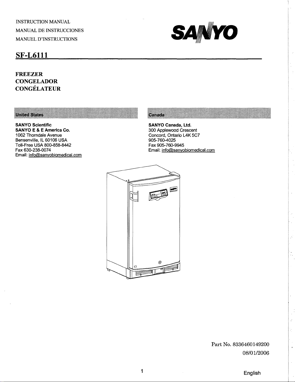
User Manual

Page 1
INSTRUCTION MANUAL MANUAL DE INSTRUCCIONES MANUEL D'INSTRUCTIONS
SF-L6111
FREEZER CONGELADOR CONGELATEUR
SANYO Scientific SANYO E & E America Co.
1062 Thorndale Avenue Bensenville, Toll-Free USA 800-858-8442 Fax 630-238-0074 Email: info@sanyobiomedical.com
IL 60106 USA
SANYO Canada, Ltd.
300 Applewood Crescent Concord, Ontario L4K 5C7 905-760-4025 Fax 905-760-9945 Email: info@sanyobiomedical.com
1
Part
No. 8336460149200
08/01/2006
English
Page 2
Note:
1.
No part
permission
2.
The contents
3.
Please contact sANYO
inaccuracies.
of
this of
manual may be reproduced in any
sANYO.
of
this
manual are
if
any
subject
point
to
change
in
this
form
without
manual
without
notice.
is
unclear
the express written
or
if
there are any
© 2006 SAN
CONTENTS
PRECAUTIONS FOR SAFE OPERATION CAUTIONS FOR USAGE ENVIRONMENTAL CONDITIONS FREEZER COMPONENTS INSTALLATION START-UP OF UNIT OPERATING INSTRUCTIONS
ALARMS AND SAFETY
DEFROSTING MAINTENANCE TROUBLESHOOTING
YO
E & E America Co. All rights reserved.
P.3 P.
7 P.8 P.8 P.11 P.12 P.
13
FUNCTIONS
P. P. P. P.
16
16
17
18
DISPOSAL OF UNIT
SPECI FICATIONS
PERFORMANCE
SAFETY
CHECK SHEET
2
P.
18 P.
19 P.
19 P.20
English
Page 3
PRECAUTIONS FOR SAFE OPERATION
It
is
imperative that the user complies with this manual as it contains
important safety advice.
Items and procedures are described the precautions advised are followed, this will prevent possible injury to the user and any other person.
in
Precautions are illustrated
the following way:
so
that you can use this unit correctly and safely. If
~WARNING
Failure to observe WARNING signs could result possibly resulting
in
serious injury or death.
in
a hazard to personnel
~CAUTION
Failure to observe CAUTION signs could result damage to the unit and associated property.
Symbol shows;
L this symbol means caution.
(S)
this symbol means an action
this symbol means an instruction must be followed.
Be
sure to keep this manual
< Label
This mark is labeled enclosed to prevent electric shock.
on
the
unit>
in
on
is
prohibited .
a place accessible to users of this unit.
the cover
in
which the electrical components of high voltage are
in
injury to personnel and
The cover
should
be
removed by qualified engineers
3
or
service personnel only.
English
Page 4
PRECAUTIONS FOR SAFE OPERATION
[
'"
Do
not
'\.Y water.
_____
use the
unit
Lt_!W_A_R_N_1
outdoors. Current leakage or electric shock may result if the unit is exposed to rain
N_G
________
]
onl
qualified
Y
O
personnel may cause electric shock or fire.
Be sure
O
not adequate, injury may result from the unit
'"
Never install the
to
engineers
install the
unit
or
service personnel should install the unit. Installation by unqualified
unit
on a
sturdy
in a humid place
floor. If the floor
falling or tipping over.
or
a place where
is
not strong enough or the installation site is
it
is
likely
to
be splashed
'\.Y Deterioration of the insulation may result which could cause current leakage or electric shock.
(S)
Never install the
'"
Never install the
unit
in a flammable
unit
where acid
or
volatile location. This may cause explosion or fire.
or
corrosive gases are present
as
current leakage or electric shock
'\.Y may result due to corrosion.
OMake
O
O
sure a dedicated power source
Make sure
plug or improper insertion may pose a hazard.
Use a power not grounded, it will
to
remove
supply
dust
from
outlet
be
with
necessary to have qualified engineers install a ground.
is
used as indicated
the power
ground (earth) to prevent electric shock. If the power supply outlet
supply
on
the rating label attached to the unit.
plug before inserting
in
a power source. A dusty
by
water.
is
'"
Never
'\.Y grounding may cause electric shock
'"
Do
ground
not
insert metal objects such as a pin
the
unit
through
a gas pipe, water main, telephone line
in
the case of
an
incomplete circuit.
or
a wire
into
any vent, gap
or
lightning rod. Such
or
any outlet for inner air
'\.Y circulation. This may cause electric shock or injury by accidental contact with moving
(S)
Never store volatile
'"
Never store corrosive substances
'\.Y electric
If
O
that
area check sheet for maintenance personnel.
this
it
parts.
unit
is
to
is
in a safe area. Failure to do
and
the local environment.
or
be used
flammable substances
in
this unit. This may lead to damage to the inner components or
for
storing poisons, radioactive material
so
In
this
case,
in
this unit. This may cause explosion or fire.
may lead to
a request for repair or maintenance will necessitate a safety
an
4
or
adverse effect
other
harmful products, ensure
on
the health of personnel
parts.
in
the
English
Page 5
PRECAUTIONS FOR SAFE OPERATION
l
___
~
Always
~
order to prevent electric shock or injury.
disconnect
&_!W_A_R_N_IN_G
the power
supply
to
the
unit
prior
to
____
any repair
J
or
maintenance of the unit in
o Ensure
maintenance. These may
(S)
Never
t<i'\ Never disassemble, repair,
\J)I
unauthorized person may result
~
Disconnect the power
~
operation may cause electric shock or fire.
If the unit
O
do
The
O
doors
Make sure
O
of service
you
do
not
inhale
splash
not
have access and
disposal
to prevent accidents such as suffocation.
water directly onto the
is
to
be
stored unused
of
the
to
prepare a safety check sheet when you request any repair or maintenance for the safety
personnel.
or
be
supply
that
unit
should be accomplished by appropriate personnel. Always remove
consume medication
harmful to your health.
unit
as
this may cause electric shock or short circuit.
or
modify
in
fire or injury due to a malfunction.
plug
in
an
doors
cannot be closed completely.
the
if
there
is
something
unsupervised area for
or
unit
yourself. Any such work carried out by
aerosols from around the unit at the time of
an
wrong
with
the unit. Continued abnormal
an
extended period, ensure
that
children
o Select a level and sturdy
Improper installation may result
Connect the
O
any other
When removing the plug from the
O
Pulling the cord may result
IC\
Never damage
\..Y
loose. This may cause fire or electric shock.
IC\
Do
not
\..Y
may cause electric shock.
unit
to
voltage or frequency other than that
or
break the
touch
any electrical parts such as the power supply plug or any switches with a wet
floor
for
in
water spillage or injury from the unit tipping over.
a power source as indicated on
in
electric shock or fire by short circuit.
power
installation. This precaution will prevent the unit from tipping.
the
power
supply
rating label attached
on
the rating label may cause fire or electric shock.
supply
plug
outlet, grip the power
or
cord. Do
5
not
use the
supply
supply
to
the unit.
plug, not the cord.
plug
if
its
hand.
Use
cord
of
is
This
English
Page 6
PRECAUTIONS FOR SAFE OPERATION
[
_____
'"
Do not climb onto the unit
\Y
damage to the unit.
(9
Do not store bottle or cans
the frozen.
'"
Do
not touch any stock (especially metal objects)
\Y
cause frostbite.
6_!
or
in
_CA_U_T_IO_N_J
do not put articles on the unit. This may cause injury by tipping or
the refrigerator. This may cause injury by broken of containers due to
in
the refrigerator with a wet hand. This may
o Always hold the handle when closing the door. This will reduce the likelihood of a trapped finger.
(9
Do not lean on the door. This may cause injury if the unit tips over.
l!f'I'
Always disconnect the power supply plug before moving the unit. Take care not to damage the
~
power cord. A damaged cord may cause electric shock or fire.
ODispose
splashed water may cause current leakage or electric shock.
o
Be
of
water
careful not to tip over the unit during movement to prevent damage or injury.
in
the evaporation tray completely prior to the movement. Spilled water or
C Always disconnect the power plug when the unit is not used for long periods.
o Make sure to check the setting value when starting up the operation after the power failure or
of
power off. A change
(9
Do not put the packing plastic bag within reach
setting value may cause damage to contents.
of
children as suffocation may result
6
English
Page 7
CAUTIONS FOR USAGE
1. If the unit is unplugged or the power to the unit is interrupted, do not restart the unit for at least 5 minutes.
This protects the compressor.
2. This inner cabinet is refrigerated by the forced circulation of cooled air inside the chamber. Ensure that
the intake and exhaust vents are not blocked. Adequate space should the unit to allow air circulation.
3. Never store corrosive materials such as acid or alkali unless the container is completely sealed up.
Corrosion may lead to failure of the unit in time.
4. Once the chamber temperature has stabilized, put the items into the chamber in small batches to minimize
the temperature increase.
be
provided between the items inside
5. Place items
air circulation.
on
the shelves and leave a space between the walls of the cabinet and the contents to allow
6. Always close the door firmly. The door check lamp is lit when the door is open. The alarm buzzer
be
sounds after two minutes the door is kept open. The buzzer can closed.
canceled automatically when the door is
7. Always open and close the door gently. Rough operation may lead to stored items falling down,
incomplete closing, or damage of door gasket.
8. Do not let items contact the wall.
9. If
an
instrument requiring a power source is to the access port replaced to seal the access port. Failure to do this and lead to condensation
on
the right side of the cabinet. After using the port, the rubber cap and insulation should be
on
the outside of the access port.
be
placed inside the cabinet, the cable can
can
affect the temperature uniformity inside the cabinet
be
led through
10. Do not clean the unit with scrubbing brushes, acid, thinner, solvents powdered soap, cleanser or hot
be
water. These agents can scratch the paint or cause it to peel. Plastic and rubber parts can
damaged by these materials. Especially never use any volatile solvent to clean the plastic or rubber parts.
When a neutral dishwashing detergent is used to clean the unit, wipe it up thoroughly with a cloth soaked in
clean water.
easily
11. If condensation forms
12. The heat discharge pipe is attached inside of the both side & rear frame. The frame sometimes gets hot
at the start-up of the operation, but this does not mean that a malfunction has occurred.
on
the door or frame surface, wipe it off with a dry soft cloth.
7
English
Page 8
ENVIRONMENTAL CONDITIONS
This equipment is designed to be safe at least under the following conditions:
1.
I ndoor use;
2.
Altitude up to 2000 m;
3.
Ambient temperature
15°C
to 26°C;
4. Maximum relative humidity 75 % for temperature up to 26
5.
Main supply voltage fluctuations not to exceed ±10% of the nominal voltage;
6.
Other supply voltage fluctuations as stated by the manufacturer;
DC;
FREEZER COMPONENTS
1.
Control panel
5.
Access port
4. Door
handle
2.
Air intake vent
8
3.
Lock
7.
Leveling feet
English
Page 9
FREEZER COMPONENTS
8.
Shelves
10. Temperature sensor (behind the fan cover)
9.
Magnetic door gasket
.--
1. Control panel: The operation status is displayed on this panel; temperature setting is also available.
Refer to page
2. Air intake vent: Ensure this vent is never blocked. Failure to do so will result in unstable temperature
distribution in the freezer.
3. Lock: Turn the key clockwise through 180 degrees to lock the door.
4.
Door handle: Always hold the handle when opening or closing the door.
5.
Access
6.
Remote alarm terminal: This may be used to trip an alarm if unit is switched off, unplugged or power to
unit is otherwise cut.
7.
Leveling feet: Use these to adjust the height and level the unit for installation.
8.
Shelf: Items
for each shelf is 28kg. Do not place stored items directly onto the interior floor
10
port:
for
details.
This port allows cables to be passed into the cabinet.
See page 15.
to
be stored in the chamber must
be
placed on the shelves. The maximum storage weight
6.
Remote alarm terminal (behind the kick plate)
of
the chamber.
9.
Magnetic door gasket: This prevents cold air from escaping. Always keep clean.
10. Temperature sensor: Located on the rear
of
the chamber, behind the fan cover.
9
English
Page 10
FREEZER COMPONENTS
Control panel
9
o
DOOR
8
o
ALARM
Q
~
1
1.
Alarm test key (ALARM TEST): Buzzer
key.
Pressing this key second time will deactivate the alarm.
2
3 4
will
sound
and
remote alarm will
7
-,
,-,
~
TEMPERATURE(-C)
-,
I
--
8CD
5
be
activated by pressing this
6
2.
Alarm buzzer stop key (BUZZER): Press this key to silence the buzzer
operates
3.
4. By pressing the key again after setting, the set value is accepted.
5. activated by pressing this key for more than 5 seconds operation"
6. value to change. "ON-OFF"
and
buzzer sounds. See page
Defrost key (DEF): Defrost will
Set key (SET): Pressing this key activates temperature set mode and the digit that can
Digit
shift
key ( ): Pressing this key
on
page
15.
Numerical value
shift
key ( ): Pressing this up arrow key
be
15
for details.
started
in
by
pressing this key for more than 5 seconds.
set mode causes the changeable digits to move. Key lock is
in
the temperature display mode. See "Key lock
in
the setting mode causes the numerical
in
the event that the alarm
be
set is flashed.
,
:1
10
English
Page 11
INSTALLATION
Installation site
To
operate this unit properly and to obtain maximum performance, install the unit
following conditions:
in
a location with the
1. A location Installation
2. A
location Always keep inadequate cooling.
3. A
location Avoid installing the unit near heat-emitting appliances such as gas ranges or stoves.
4. A
location Install the unit cause vibration and noise.
~
WARNING
Be
sure
adequate, this may result
~
CAUTION
Select a level and Improper installation may result
not
subjected
in
a location subjected to direct sunlight might lead to inadequate cooling.
with
adequate
in
front of air intake and exhaust area open for free air circulation. Poor ventilation will result
away
from
with a sturdy
on
a sturdy floor to avoid vibration and noise. Placing the unit
to
install the
sturdy
to
direct
sunlight
ventilation
heat generating
and level
unit
on a sturdy
in
injury from the unit falling or tipping over.
floor
in
water spillage or injury from the unit tipping over.
sources
floor
floor. If the floor
for
installation. This precaution will prevent the unit from tipping.
is
not strong enough or the installation site
on
an unsteady floor may
is
in
not
5. A location
~
WARNING
Do
not water. Never Deterioration of the insulation may result which could cause current leakage or electric shock. Do
not
could cause current leakage or electric shock.
6. A
location Avoid placing the unit where chemicals are stored or gases are produced. great
deal
~
WARNING
Never Never result due to corrosion.
install install
not
use
the
install
install the
of
dust.
the
without
the
the
prone
unit
unit unit
to
high
humidity
outdoors. Current leakage or electric shock may result if the unit
unit
in a
unit
under
a flammable
in a flammable where acid
humid
water
place
pipes
or
corrosive
or
or
corrosive
or
a place where
or
steam pipes. Deterioration of the insulation may result which
gas
volatile
location. This may cause explosion or fire.
gases are present
it
is
likely
Also avoid areas where there
as
current leakage or electric shock may
to
be splashed
is
11
exposed to rain
by
water.
is
English
a
Page 12
INSTALLATION
Installation
1.
Remove the packaging materials and tapes Remove
tapes.
neutral
dilution, refer to the instruction of the detergent.) After
it
off with a wet cloth, then wipe the panels with a dry cloth.
2.
Apply should mounted at the
3.
~WARNING
Use a power
grounded,
Never
grounding may cause
Open the doors and ventilate the unit. If the outside panels are dirty, clean them with a diluted
dishwashing detergent. (Undiluted detergent can damage the plastic components. For the
Door
handle installation
door handle, plastic washer and screw and fasten the screw. For floor-level installation the handle
be mounted at the higher location. For stacking above another compatible unit, the handle should be
lower location.
Ground (earth)
supply
qualified personnel must install a ground.
ground
outlet
the
unit
electric shock
through
Remove the two plugs from the door where you will attach the door handle.
with
ground
(earth) to prevent electric shock. If the power supply outlet
a gas pipe,
in
the case of
all
transportation packaging materials and
cleaning with the diluted detergent, always wipe
water
an
main, telephone line
incomplete circuit.
or
lightning
is
not
rod. Such
START-UP OF UNIT
The following procedures should be adhered to for initial start-up and continuous operation.
1.
Connect the unit to dedicated power supply.
2.
Set the desired temperature.
3.
Confirm that the chamber temperature
you
4. When minimize the temperature rise.
5.
As this freezer's shelf is also than the freezer). product's desired temperature
are satisfied that the unit
displayed temperature. (The displayed temperature is the same as the air temperature inside
Placing heat insulation material such as plastic between shelf and product
an
is
is
evaporator, the surface of the shelf will reach a much colder temperature
the freezer's displayed temperature.
is
working correctly, begin slowly placing product into the chamber to
Do
not put any product
at the desired temperature.
in
the unit at this time.
is
required if the
of
the
12
English
Page 13
OPERATING INSTRUCTIONS
Temperature setting
Table 1 shows the basic operation method. Perform key operation The example
Note: The unit
Table 1 Basic operation procedure (Example of setting: Freezer @ -25°C)
Operation Key operated Display after the key operation Connect
1
2 Press SET
3
Set to 5 by using the up arrow key.
Set to 5 by using the digit shift key
and
4
5
Press
Note:
If no key has been pressed for about automatically to the temperature display mode. The freezer temperature can
in
the table
is
to
the
key.
numerical value shift key.
SET
key.
is
based
set at the factory at
power
source
. ----- The current freezer temperature
be
on
the assumption that the freezer temperature
-20
°C.
is
displayed. When freezer
is
higher than
LO
is
displayed when lower than
SET The first digit of the temperature
display flashes.
Pressing the up arrow key shifts the flashing digit by one. Repeat until flashing digit turns to
Pressing the digit shift key leads the
flashes of the next digit.
Pressing the up arrow key shifts up the flashing digit by one. Repeat until flashing digit turns to The value (-25) and the current freezer temperature is
displayed.
in
the temperature set mode, the display mode returns
this case, the chamber temperature setting
set
SET
90
seconds
In
in
the range between -15 and -25°C. Remember that the guaranteed
in
the sequence indicated
30°C,
is
stored
is
-25°C.
temperatur~]
HI
is
displayed and
5.
2.
in
memory
-36°C.
up
is
in
the table.
FH
f'
iff
1-1215]
~,
~
[H[
I
[ ! I
not changed.
temperature with
no
load at
an
ambient temperature of
21°C
13
is
-15 and
-25°C.
English
Page 14
OPERATING INSTRUCTIONS
Offset
The difference between chamber and indicated temperature can be arranged by key operation.
As an
example, Table 2 shows the procedure
in
case actual freezer temperature
is
-25
ce
and displayed
temperature
T
able 2
Operation
Pressing the up arrow key more The first digit
1
than
Set to 2 by using
2 Up arrow key. by one
Press the set key.
3
is
-27
ce,
change the displayed temperature to
Offset setup procedure
5 seconds.
-25
Key operated
Display after the key operated
The current freezer temperature
Is displayed.
display flashes.
t
Pressing the key shifts up the figure
t
3,
.....
until flashing digit turns to 2.
SET The current adjusted temperature
(offset by
ce.
of
the temperature
in
the following sequence:
8,9,
-9, -8, ... , -1,
+2
degrees)
O.
is
Repeat
displayed.
1-12171
1,
2,:-'
'D t.:,!
i
2!
' ,
1-12151
14
English
Page 15
OPERATING INSTRUCTIONS
Key lock operation
This unit incorporates a key lock feature that can inhibit tampering using the keys The key lock
Table
3 Key lock setup procedure (Example: Key lock OFF
Operation
1 Press and hold the digit shift
key for about 5 seconds. or L01)
2 Set the first digit to 1 with
the up arrow key.
3
Press the set key. SET Key lock
Note:
lock can be set any time when the current refrigerator temperature
Key
is
set to OFF at the factory.
Display Mode Function
LoO L01
Key lock OFF Temperature change enabled Key lock
ON
Key operated
~
t
Temperature change disabled
=>
Key lock ON)
Display after the key operated
The current freezer temperature is
The current key lock status (either
is
displayed.
Pressing the key alters 0 and Choose 1 to turn function.
is
freezer temperature is
set to
is
displayed.
on
the key lock
ON
and the current
on
the control panel.
LoO
1.
displayed.
displayed.
II!
In
L.!D~lI
I!
! »
LID~
I
Remote alarm terminal
The terminal of the unit. The between terminal 1 and terminal Contact capacity
At normal condition A 1 and A2 are "Open" At abnormal condition A 1 and A2 are "Closed" The remote alarm to be connected to
Note:
The
alarm is actuated when the power cord
from the
of
the remote alarm
alarm
is
DC 30V, 2
outlet and the power switch
is
is
outputted from this terminal
2.
A.
installed
81
is
OFF.
aUhe
and 82.
is
disconnected
bottom
A
B
15
English
Page 16
ALARMS AND SAFETY FUNCTIONS
lights up.
Temperature display flashes.
lights up.
Temperature display flashes.
This unit has the alarm and safety functions shown
T
bl 4
a
Kind
of
or
safety
High temperature exceeds the set temperature alarm
Low temperature alarm
Power failure alarm
Door alarm
Auto return
AI
e arms an
alarm
If the chamber temperature Alarm more If the chamber temperature Alarm
is
lower
temperature. In
the event of a power Display shuts failure or disconnection of activated. power outlet
When
If a
key performed for about seconds mode.
d
~
t f f sa ery
unc
Ions
Situation Indication Buzzer Safety operation
than
3°C.
3°C
than
the set
supply
plug
from the
the
door
is
operation
in
each
open.
is
not Chamber temperature
90
setting
Door
displayed.
in
Table 4, and also a self-diagnostic function.
lamp
flashes.
lamp
flashes. Intermittent tone
off.
check
lamp
is
lit. Intermittent tone
is
Intermittent tone
delay of
after a
minutes.
delay of
after a minutes.
-----
after a delay of 2 minutes.
-----
Remote
15
activated after a delay of
Remote
15
activated after a delay of
Remote
-----
Setting canceled.
alarm 15 alarm 15 alarm
mode
is
minutes.
is
minutes.
is
is
Key
lock
Thermal sensor If the thermal sensor goes abnormality
When
the
key lock
'L
1).
open
(E01/LO)
or short circuit (E01/HI).
the defrost sensor goes E02and chamber temperature
If Open
(E02)or short circuit
(E02).
is
Note:
The
alarm can be canceled silenced. After
a power failure, the unit will resume operation with the set value that was
occurred.
by
DEFROSTING
The
defrosting is activated when DEF
Remove bottom in order prevent water the evaporator. After defrosting, remove of
and store the content to other freezer before starting the defrosting. Place cotton bath towels
of
to
the unit.
the freezer
quicken defrosting. If bath towels are soaked, remove from the chamber,
to
drip
chamber
out
of
chamber.
before the start
ON
pressing
key
Do
-----
E01
and
LO(E01
are
displayed alternately
temperature display. are
displayed alternately
temperature display.
the
alarm buzzer stop key (BUZZER), but the remote alarm cannot be
is pressed more than 5 seconds.
of
defrosting
not try
wet
to
towels, dry inside chamber with
and
HI)
on
on
as
the defrost water will fall. Keep the
physically remove ice as
-----
----- Compressor operates
the
the
that
may
dry
soft clothes before re-start
Key
input
continuously. Normal
defrost will passed.
in
place before
dry
them and replace
cause the
is
unable.
running
be
power
door
damage
at
open
and
failure
the
to to
Pressing the DEF key
for
more than 5 seconds will restart the operation
16
of
the freezer.
English
Page 17
While
10 / 02 / 2006
you
are
defrosting
. . . .
Freezer minutes recommended
absorbing have a buzzer
defrosting)
is
desigried
to
remind
material
or
to
that
that
you
is
tone,
you
unplug
send a buzzer
the
defrosting
would
dry
the
check
enough
have a choice
power
to
cord
message
is
in
process,
the
freezer
continue
to
either
until
defrost
(but
not
remote
if
the
at
each
defrosting.
close
the
is
completed.
door
buzzer
Just
door
alarm)
is
kept
to
assure
in
case
(which
for
every
open.
the
you
will
We water
rather
delay
30
not
Page 18
MAINTENANCE
&WARNING
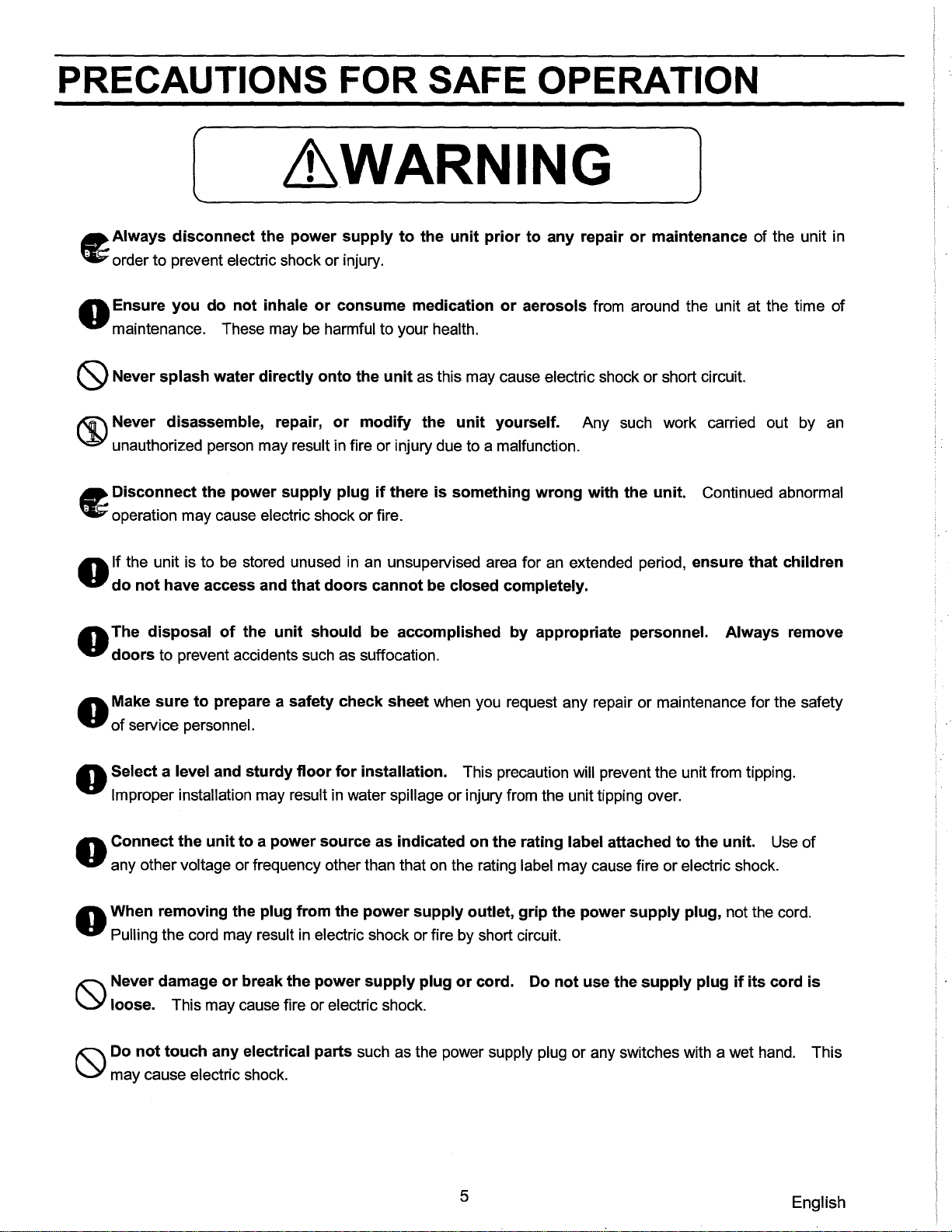
Always disconnect the power supply to the unit prior to any repair or maintenance
to prevent electric shock or injury. Ensure you do not inhale or consume medication or aerosols from around the unit at the time of maintenance. These may
be
harmful to your health.
Cleaning
• Clean the unit once a month. Regular cleaning keeps the unit looking new.
of
the unit
in
order
• Use a dry cloth to wipe off small amounts
the outside panels are dirty, clean them with a diluted neutral dishwashing detergent. (Undiluted detergent can damage the plastic components. For the dilution, refer to the instruction cleaning with the diluted detergent, always wipe it off with a wet cloth. Then wipe off the cabinet or accessories with a dry cloth.
• Never pour water onto or into the unit. Doing so electric shock or short circuit.
• The compressor and other mechanical part are completely sealed. This unit requires absolutely
lubrication.
of
dirt
on
the outside and inside
can
damage the electrical insulation and may cause
of
the unit and all accessories. If
of
the detergent.) After the
no
Stacking two units
• You
can
stack two freezers, or the floor space efficiency. To stack two units, 833-0-3131-101-00. The stacking instructions stacking will bring the center of gravity significantly higher than when one unit
&WARNING
Always disconnect the power supply to the unit prior to stacking two units
shock or injury.
Any stacked combination of
provided with the stacking accessory kit.
When stacking the freezer and the refrigerator, always keep the freezer at the bottom
you
can stack this freezer and SR-L6111W (laboratory refrigerator) to double
you
must order the stacking accessory kit part number
in
SAN
the accessory kit must
YO
refrigerator and I or freezer must
be
obeyed strictly for safety,
is
placed on the floor.
in
order to prevent electric
be
secured using
all
as
hardware
17
English
Page 19
TROUBLESHOOTING
If the unit malfunctions, check the following potential causes before calling for service. inadequate refrigeration or freezing, transfer the stored items to another freezer before checking.
If
nothing
1.
The unit
2. There is a power failure, the fuse
When
1.
The key lock
When alarm
On start-up
1. The temperature
In
use
operates even
is
not connected to the power supply or capacity
the
unit
does
is
is
activated
when
the
unit
is
plugged
is
blown,
not
accept
not "OFF". See page 15 for "key lock."
in
the unit does not match set value.
changes
or
of
set-point
in
the circuit breaker
temperature
of
power source
is
activated.
is
not enough.
1. The door was kept open for a long time.
2. The set value was changed.
3. Vessels containing a high temperature load were put
In
these cases, the alarm may be deactivated automatically
in
the unit.
by
running the unit for several hours.
In
the case of
the
unit
does
not
cool
When
1. The air exhaust vent
2. A
large amount of warm objects was put
3. Some heat sources
4. The door
is
opened frequently.
is
in
5. The ambient temperature
6. The unit
7. The door
8. The door seal
9.
Check the "offset," to make sure set temperature
is
in
direct sunlight.
is
not securely closed.
is
damaged or foreign substance inserted between the door gaskets.
adequately
blocked by freezer contents.
in
the unit.
the unit.
is
too high.
DISPOSAL OF UNIT
&WARNING
If the unit not
The
prevent accidents such as suffocation.
is
to be stored unused
have access and
disposal
of
the
that unit
doors
should
in
an
unsupervised area for
cannot
be
closed
be performed
is
not offset. See page
an
extended period ensure
completely.
by
appropriate
personnel.
14
for "offset."
Always
that
children
remove
doors
do
to
18
English
Page 20
SPECIFICATIONS
Name Model External dimensions Internal dimensions Effective capacity Exterior Interior Door Insulation Shelf
Access port Cooling method Compressor Evaporator Condenser Refrigerant Defrosting Defrost heater Temperature Temperature Thermal
Alarm & Safety
Memory backup Weight Accessories Option
controller
display
sensor
345/8"
2713/16" H x
Polyethylene
20" W x 169/16" D (508 W x
Size:
High temperature
Laboratory Freezer
SF-L6111
H x
235/8"
Galvanized steel, polyester resin baked finish
Inner diameter 1 3/16" (30 mm), 1 port
Wire and tube type, evaporator serves as
alarm, Low temperature alarm, Power failure remote alarm, Door alarm
Stackable
W x 25 31/32" D (880 H x 600 W x 652 D (mm))
207/8"
coated pipe and wire.
Tube with wire at the bottom of the unit
W x 175/16" D (706 H x 530 W x
5.5 Cubic Feet (156
Vacuum formed plastic
Rigid polyurethane foamed-in-place
421
Forced air
Reciprocal type, output; 142 W
Manual defrosting
Microprocessor control system
Digital display
Thermistor sensor
Key lock, Thermal sensor abnormality
Nonvolatile memory
117
kit, part number 833-0-3131-101-00
circulation
R-134a
None
Ibs,
(53 kg)
1 set of keys
liters)
Shelves function as evaporator.
D (mm))
Max.
on
the right side
shelves
load; 28 kg/shelf
441
D (mm))
Note:
Design or specifications will be subject to change without notice.
PERFORMANCE
Control range Rated voltage
Rated frequency
Power
consumption
Freezer:
-25°C to
-15°C
19
(Ambient temperature
AC
115 V
60
Hz
96W
21°C,
no load)
English
Page 21
6 CAUTION
Please fill
Provide this form to the service engineer to keep for safety.
in
this form before servicing.
1.
Freezer
Risk of infection: Risk of toxicity: Risk from radioactive sources:
(List
Notes:
2.
Contamination
Unit interior No contamination Decontaminated Contaminated Others:
contents:
all potentially hazardous materials that have been stored
of
the unit
Safety
DYes DYes
0 Yes 0 No
DYes DYes DYes
check
o No
o No
o No o No o No
sheet
in
this unit.)
3.
Instructions for safe repair/maintenance
a) The unit is safe to work on b) There is some danger (see
Procedure to be adhered to
Date: Signature: Address, Division:
Telephone:
Product name: Model: Laboratory Freezer
Please decontaminate the unit yourself before calling the service engineer.
SF-L6111
below) 0 Yes 0 No
in
order to reduce safety risk indicated
of
the unit
0 Yes 0 No
Serial
in
number:
b) above:
Date of installation:
20
English
Loading...