

SANYO SB16-04LHP Datasheet

SB16-04LHP
Ordering number : EN5538A
Rectifier
Schottky Barrier Diode
SANYO Electric Co.,Ltd. Semiconductor Bussiness Headquarters
TOKYO OFFICE Tokyo Bldg., 1-10, 1 Chome, Ueno, Taito-ku, TOKYO, 110 JAPAN
Features
⋅ Meets the requirements for automatic mounter and
permits SB16-04LHP-applied sets to be made compact.
⋅ Low forward voltage (VF max = 0.55 V).
⋅ Average rectified current : Io = 1.6 A.
Absolute Maximum Ratings at Ta = 25 ˚C
Package Dimensions
unit: mm
1275
[SB16-04LHP]
Parameter Symbol Conditions Ratings Unit
Peak Reverse Voltage V
RM
40 V
Non-repetitive Peak Reveres Surge Voltage V
RSM
45 V
Average Rectified Current Io 50 Hz sine wave, mounted on an alumina board
Load resistor, mounted on a PCB
50 Hz sine wave, nonrepetitive, 1 cycle peak value
1.6 A
1.3 A
Surge Current
Junction Temperature
Storage Temperature
I
FSM
Tj
Tstg
60
125
–55 to +125
A
˚C
˚C
Electrical Characteristics Ta = 25 ˚C
Parameter Symbol Conditions
Ratings
Unit
min typ max
Forward Voltage V
F
IF=1.6 A
V
R=VRM
VR=10 V, f=1 MHz
Junction-Lead
Junction-Ambient Mounted on an alumina board
Mounted on a PCB
0.55 V
Reverse Current
Interterminal Capacitance
Thermal Resistance
I
R
C
θj-l
θj-a
150
2.5
24
90
120
mA
pF
˚C/W
˚C/W
˚C/W
63097GI(KOTO) No.5538-1/3
Cathode mark
SB16-04LHP
No.5538-2/3
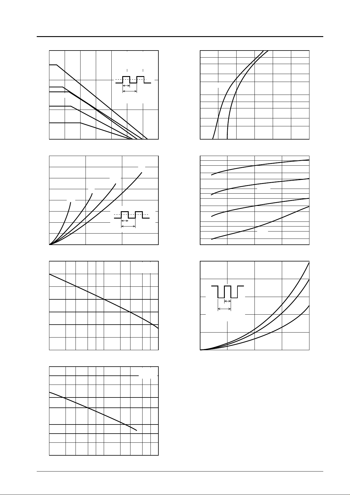
Reverse Voltage, V
R
— V
0 20 40 60 80 100 120 140
0
1.0
2.0
3.0
Ambient Temperature, Ta
— ˚C
Average Rectified Current, I
O
— A
IO — Ta
Resistive load
Alumina board
VR=1/2V
RM
DC
D=0.5
0.2
0.05
Sine wave
0 0.2 0.4 0.6 0.8 1.0 1.2
0.1
2
3
5
7
1.0
2
3
5
7
10
Forward Current, I
F
— A
IF — V
F
Ta=125˚C 25˚C
0 10 20 30
0
0.2
0.4
0.6
0.8
1.0
1.2
1.4
1.6
Average Output Current, I
O
— A
Forward Power Dissipation, P
F
— W
PF — I
O
0.05
0.2
D=0.5
DC
0 –10 –20 –30 –40
2
3
5
7
10
2
3
5
7
10
2
3
5
7
10
Reverse Voltage, V
R
— V
Reverse Current, I
R
— mA
IR — V
R
Ta=125˚C
100˚C
75˚C
50˚C
Number of Cycles at 50Hz, n
0 2 3 5 7 10 2 3 5 7 100
0
10
20
30
40
50
60
70
Surge Forward Current, I
FSM
— A
I
FSM
— m
50Hz
Ta=125˚C
0 10 20 30 40
0
0.2
0.4
0.6
0.8
1.0
Reverse Voltage, V
R
— V
Reverse Power Dissipation, P
R
— W
PR — V
R
DC
0.2
D=0.5
0 2 3 5 7 10 2 3 5 7 100
3
5
7
100
2
3
5
7
1000
Reverse Voltage, V
R
— V
Interterminal Capacitance, C — P
F
C — V
R
f=1MHz
Ta=25˚C
Vr
0
tp
T
D=tp/T
I
f
0
tp
T
D=tp/T
I
O
I
f
0
tp
T
D=tp/T
I
O
 Loading...