

Sanyo SAP–K181AHA, SAP–K121AHA, SAP–C181AHA, SAP–K241AHA, SAP–C241AHA Technical & Service Manual
...
AustraliaGeneral (50Hz)
TECHNICAL & SERVICE MANUAL
SAP–K91AHA + SAP–C91AHA
SAP–K121AHA + SAP–C121AHA
FILE NO.
REFERENCE NO. SM700462
Indoor Unit Outdoor Unit
SPLIT SYSTEM AIR CONDITIONER
80%
SAP–K91AHA
SAP–K121AHA
SAP–C91AHA
SAP–C121AHA
Indoor Model No. Product Code No. Destination
SAP–K91AHA–S 1 852 070 75
SAP–K121AHA–S 1 852 072 04
Outdoor Model No. Product Code No. Destination
SAP–C91AHA–S 1 852 070 83
SAP–C121AHA–S 1 852 070 84
Australia Australia
i
Important!
Please Read Before Starting
This air conditioning system meets strict safety and
operating standards. As the installer or service person,
it is an important part of your job to install or service the
system so it operates safely and efficiently.
For safe installation and trouble-free operation, you
must:
●Carefully read this instruction booklet before
beginning.
●Follow each installation or repair step exactly as
shown.
●Observe all local, state, and national electrical codes.
●Pay close attention to all warning and caution notices
given in this manual.
This symbol refers to a hazard or
unsafe practice which can result
in severe personal injury or
death.
This symbol refers to a hazard or
unsafe practice which can result
in personal injury or product or
property damage.
If Necessary, Get Help
These instructions are all you need for most installation
sites and maintenance conditions. If you require help
for a special problem, contact our sales/service outlet
or your certified dealer for additional instructions.
In Case of Improper Installation
The manufacturer shall in no way be responsible for
improper installation or maintenance service, including
failure to follow the instructions in this document.
Special Precautions
When Wiring
ELECTRICAL SHOCK CAN CAUSE
SEVERE PERSONAL INJURY OR
DEATH. ONLY A QUALIFIED,
EXPERIENCED ELECTRICIAN SHOULD
ATTEMPT TO WIRE THIS SYSTEM.
• Do not supply power to the unit until all wiring and
tubing are completed or reconnected and checked.
• Highly dangerous electrical voltages are used in this
system. Carefully refer to the wiring diagram and
these instructions when wiring. Improper connections
and inadequate grounding can cause accidental
injury or death.
• Ground the unit following local electrical codes.
• Connect all wiring tightly. Loose wiring may cause
overheating at connection points and a possible fire
hazard.
WARNING
CAUTION
WARNING
When Transporting
Be careful when picking up and moving the indoor and
outdoor units. Get a partner to help, and bend your
knees when lifting to reduce strain on your back. Sharp
edges or thin aluminum fins on the air conditioner can
cut your fingers.
When Installing…
…In a Ceiling or Wall
Make sure the ceiling/wall is strong enough to hold the
units weight. It may be necessary to construct a strong
wood or metal frame to provide added support.
…In a Room
Properly insulate any tubing run inside a room to
prevent “sweating” that can cause dripping and water
damage to walls and floors.
…In Moist or Uneven Locations
Use a raised concrete pad or concrete blocks to
provide a solid, level foundation for the outdoor unit.
This prevents water damage and abnormal vibration.
…In an Area with High Winds
Securely anchor the outdoor unit down with bolts and a
metal frame. Provide a suitable air baffle.
…In a Snowy Area (for Heat Pump-type Systems)
Install the outdoor unit on a raised platform that is
higher than drifting snow. Provide snow vents.
When Connecting Refrigerant Tubing
• Use the flare method for connecting tubing.
• Apply refrigerant lubricant to the matching surfaces
of the flare and union tubes before connecting them,
then tighten the nut with a torque wrench for a leakfree connection.
• Check carefully for leaks before starting the test run.
When Servicing
• Turn the power off at the main power box (mains)
before opening the unit to check or repair electrical
parts and wiring.
• Keep your fingers and clothing away from any
moving parts.
• Clean up the site after you finish, remembering to
check that no metal scraps or bits of wiring have
been left inside the unit being serviced.
Others
• Ventilate any enclosed areas when installing or
testing the refrigeration system. Escaped refrigerant
gas, on contact with fire or heat, can produce
dangerously toxic gas.
• Confirm upon completing installation that no
refrigerant gas is leaking. If escaped gas comes in
contact with a stove, gas water heater, electric room
heater or other heat source, it can produce
dangerously toxic gas.
CAUTION

Table of Contents
Page
1. OPERATING RANGE .............................................................................................................................. 1
2. SPECIFICATIONS
2-1. Unit Specifications.......................................................................................................................... 2
2-2. Major Component Specifications.................................................................................................... 4
2-3. Other Component Specifications.................................................................................................... 8
3. DIMENSIONAL DATA.............................................................................................................................. 9
4. REFRIGERANT FLOW DIAGRAM ......................................................................................................... 12
5. PERFORMANCE DATA
5-1. Performance charts ....................................................................................................................... 13
5-2. Air Throw Distance Chart .............................................................................................................. 15
5-3. Cooling Capacity ........................................................................................................................... 17
5-4. Heating Capacity ........................................................................................................................... 19
6. ELECTRICAL DATA
6-1. Electrical Characteristics................................................................................................................ 20
6-2. Electric Wiring Diagram.................................................................................................................. 22
7. INSTALLATION INSTRUCTIONS
7-1. Installation Site Selection ............................................................................................................... 25
7-2. Remote Control Unit Installation Position....................................................................................... 27
7-3. Recommended Wire Length and Diameter ................................................................................... 28
8. FUNCTION
8-1. Room Temperature Control ........................................................................................................... 29
8-2. Dry Operation ................................................................................................................................ 31
8-3. Automatic Switching between Cooling and Heating ...................................................................... 31
8-4. Freeze Prevention ......................................................................................................................... 32
8-5. Overload Prevention ...................................................................................................................... 33
8-6. Cold Draft Prevention .................................................................................................................... 34
8-7. Defrosting Operation ..................................................................................................................... 35
8-8. Outdoor Fan Speed Control .......................................................................................................... 36
9. TROUBLESHOOTING
9-1. Check before and after troubleshooting ........................................................................................ 37
9-2. Air conditioner does not operate .................................................................................................... 38
9-3. Some part of air conditioner does not operate .............................................................................. 42
9-4. Air conditioner operates, but abnormalities are observed ............................................................. 44
9-5. If a sensor is defective ................................................................................................................... 46
10. CHECKING ELECTRICAL COMPONENTS
10-1. Measurement of Insulation Resistance .......................................................................................... 47
10-2. Checking Continuity of Fuse on PCB Ass'y.................................................................................... 48
10-3. Checking Motor Capacitor ............................................................................................................. 48
11. MAINTENANCE
11-1. Changing Address of Remote Control Unit in Indoor Unit ............................................................. 49
INSTRUCTION MANUAL ........................................................................................................ 50
APPENDIX
ii

1
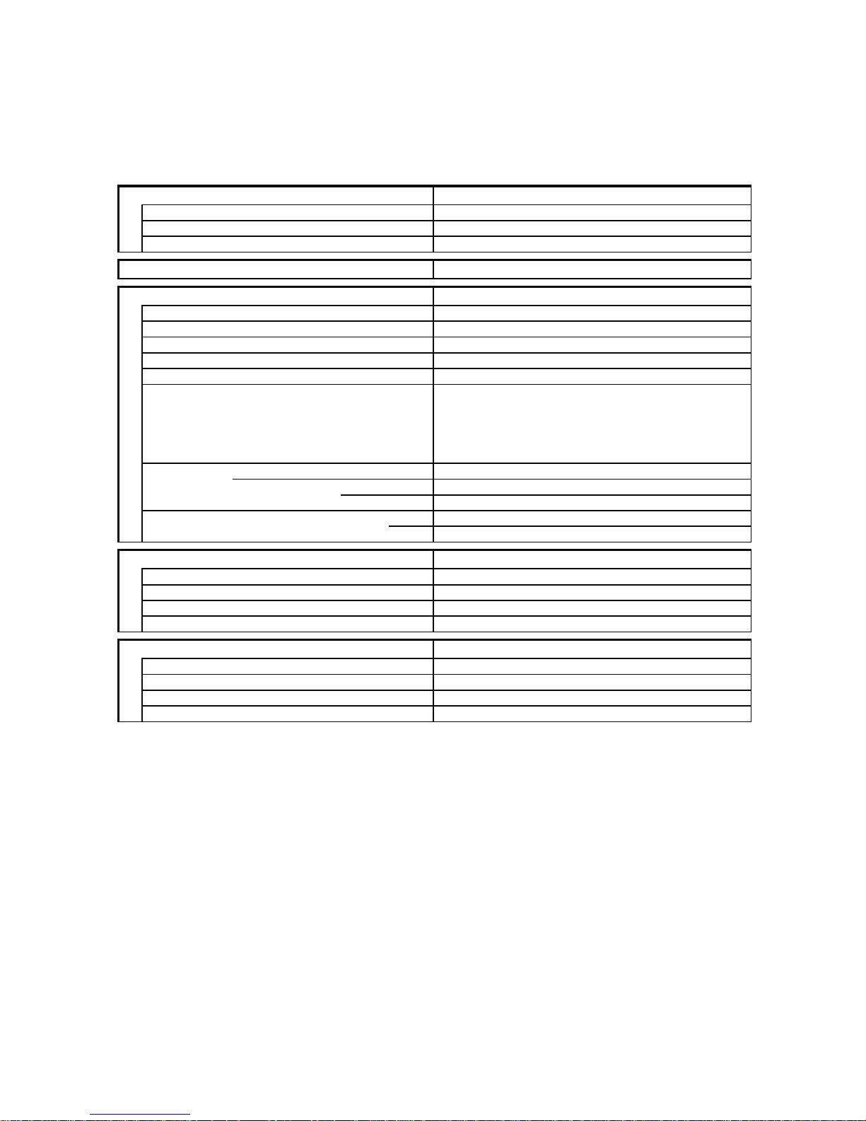
1. OPERATING RANGE
Temperature Indoor Air Intake Temp. Outdoor Air Intake Temp.
Cooling
Maximum 32°C D.B. / 23°C W.B. 43°C D.B.
Minimum 19°C D.B. / 14°C W.B. 19°C D.B.
Heating
Maximum 27°C D.B. 24°C D.B. / 18°C W.B.
Minimum 16°C D.B. –8°C D.B. / –9°C W.B.

2
2. SPECIFICATIONS
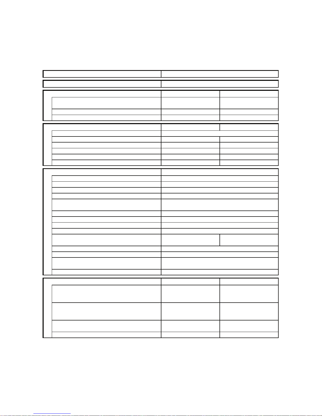
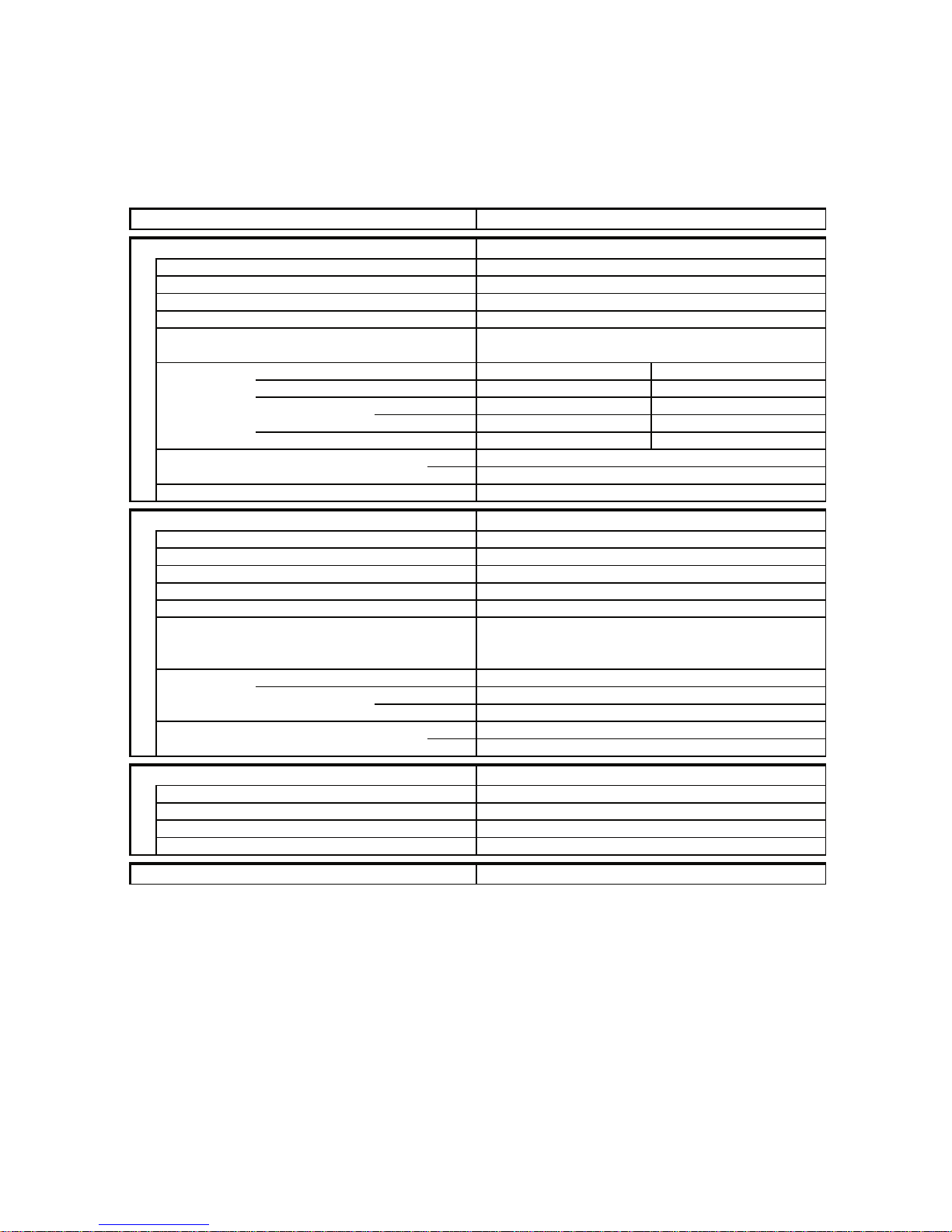
2-1. Unit Specifications
Indoor Unit SAP–K91AHA
Outdoor Unit SAP–C91AHA
Power Source 240V Single phase 50Hz
Voltage rating 240 V
Performance Cooling Heating
Capacity kW 2.50 3.20
BTU/h 8,500 10,900
Air circulation (High)
m3/h
430 430
Moisture removal (High) Liters/h 0.85 —
Electrical Rating Cooling Heating
Available voltage range V 216 ~ 264
Running amperes A 4.4 4.4
Power input W 1,020 1,020
Power factor % 97 97
C.O.P. W/W 2.45 3.14
Compressor locked rotor amperes A 24 24
Features
Controls / Temperature control Microprocessor / I.C. thermostat
Control unit Wireless remote control unit
Timer 1-hour OFF / 12-hours ON or OFF
Fan speeds Indoor / Outdoor 3 and Auto / 1(Hi)
Airflow direction (Indoor) Horizontal Manual
Vertical Auto
Air filter Washable, Anti-Mold
Compressor Rotary (Hermetic)
Refrigerant / Amount charged at shipment g R22 / 880
Refrigerant control Capillary tube
Operation sound Indoor : Hi / Me / Lo dB-A 39 / 37 / 33 39 / 37 / 33
Outdoor : Hi dB-A 44 44
Refrigerant tubing connections Flare type
Max. allowable tubing length at shipment m 7.5
Refrigerant Narrow tube mm (in.) 6.35(1/4)
tube diameter Wide tube mm (in.) 9.52(3/8)
Refrigerant tube kit / Accessories Optional / Hanging wall bracket
Dimensions & Weight
Indoor Unit
Outdoor Unit
Unit dimensions Height mm 250 530
Width mm 790 680
Depth mm 174 225
Package dimensions Height mm 242 580
Width mm 850 812
Depth mm 312 315
Weight Net kg 7.0 31.0
Shipping kg 10.0 33.0
Shipping volume
m
3
0.06 0.15
DATA SUBJECT TO CHANGE WITHOUT NOTICE.
Remarks:
Rating conditions are:
Cooling : Indoor air temperature 27°C D.B. / 19°C W.B.
Outdoor air temperature 35°C D.B. / 24°C W.B.
Heating : Indoor air temperature 20°C D.B.
Outdoor air temperature 7°C D.B. / 6°C W.B.
3
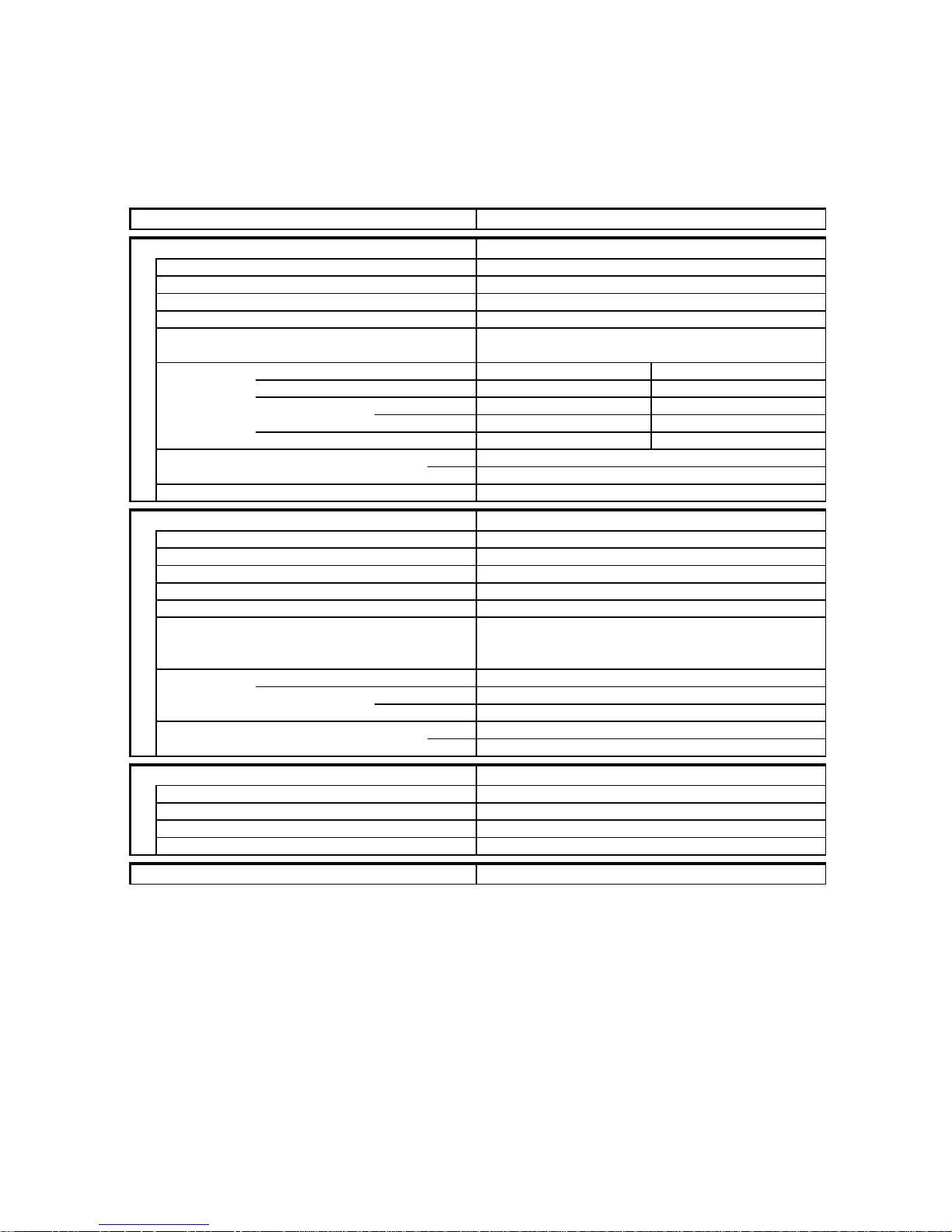
Indoor Unit SAP–K121AHA
Outdoor Unit SAP–C121AHA
Power Source 240V Single phase 50Hz
Voltage rating 240 V
Performance Cooling Heating
Capacity kW 3.20 3.75
BTU/h 10,900 12,800
Air circulation (High)
m3/h
470 460
Moisture removal (High) Liters/h 1.45 —
Electrical Rating Cooling Heating
Available voltage range V 216 ~ 264
Running amperes A 6.1 6.0
Power input W 1,350 1,320
Power factor % 92 92
C.O.P. W/W 2.37 2.84
Compressor locked rotor amperes A 35 35
Features
Controls / Temperature control Microprocessor / I.C. thermostat
Control unit Wireless remote control unit
Timer 1-hour OFF / 12-hours ON or OFF
Fan speeds Indoor / Outdoor 3 and Auto / Auto (Hi,Lo)
Airflow direction (Indoor) Horizontal Manual
Vertical Auto
Air filter Washable, Anti-Mold
Compressor Rotary (Hermetic)
Refrigerant / Amount charged at shipment g R22 / 1,010
Refrigerant control Capillary tube
Operation sound Indoor : Hi / Me / Lo dB-A 40 / 38 / 36 39 / 38 / 36
Outdoor : Hi dB-A 45 46
Refrigerant tubing connections Flare type
Max. allowable tubing length at shipment m 7.5
Refrigerant Narrow tube mm (in.) 6.35(1/4)
tube diameter Wide tube mm (in.) 12.7(1/2)
Refrigerant tube kit / Accessories Optional / Hanging wall bracket
Dimensions & Weight
Indoor Unit
Outdoor Unit
Unit dimensions Height mm 250 530
Width mm 790 680
Depth mm 174 225
Package dimensions Height mm 242 580
Width mm 850 812
Depth mm 312 315
Weight Net kg 7.0 34.0
Shipping kg 10.0 36.0
Shipping volume
m
3
0.06 0.15
DATA SUBJECT TO CHANGE WITHOUT NOTICE.
Remarks:
Rating conditions are:
Cooling : Indoor air temperature 27°C D.B. / 19°C W.B.
Outdoor air temperature 35°C D.B. / 24°C W.B.
Heating : Indoor air temperature 20°C D.B.
Outdoor air temperature 7°C D.B. / 6°C W.B.
4
2-2. Major Component Specifications
2-2-1. Indoor Unit
Indoor Unit SAP–K91AHA
Controller PCB
Part No. POW-K91GJHA
Controls Microprocessor
Control circuit fuse 250 V 3.15 A
Remote Control Unit RCS-2HS4E
Fan & Fan Motor
Type Cross-flow
Q'ty ... Dia. and length mm 1 ... ø95 / L578
Fan motor model ... Q'ty IBH-884-020 ... 1
No. of poles ... 50Hz rpm (High) 2 ... 1,290
Nominal output W 20
Coil resistance (Ambient temp. 20°C) Ω WHT-BRN : 201
WHT-VLT : 261
Safety devices Type Thermal fuse
Operating temp. Open °C 130
Close —
Run capacitor (on the PCB Ass'y) µF 1.5
VAC 440
Flap Motor
Type Stepping motor
Model MP24GA3
Rating DC 12 V
Coil resistance (Ambient temp. 25°C) Ω A pair of each terminal : 380 ± 7%
Heat Exch. Coil
Coil Aluminum plate fin / Copper tube
Rows 2
Fin pitch mm 1.4
Face area
m
2
0.110
DATA SUBJECT TO CHANGE WITHOUT NOTICE.
5
Indoor Unit SAP–K121AHA
Controller PCB
Part No. POW-K121GJHA
Controls Microprocessor
Control circuit fuse 250 V 3.15 A
Remote Control Unit RCS-2HS4E
Fan & Fan Motor
Type Cross-flow
Q'ty ... Dia. and length mm 1 ... ø95 / L578
Fan motor model ... Q'ty IBH-884-020 ... 1
No. of poles ... 50Hz rpm (High) 2 ... 1,340
Nominal output W 20
Coil resistance (Ambient temp. 20°C) Ω WHT-BRN : 201
WHT-VLT : 261
Safety devices Type Thermal fuse
Operating temp. Open °C 130
Close —
Run capacitor (on the PCB Ass'y) µF 1.5
VAC 440
Flap Motor
Type Stepping motor
Model MP24GA3
Rating DC 12 V
Coil resistance (Ambient temp. 25°C) Ω A pair of each terminal : 380 ± 7%
Heat Exch. Coil
Coil Aluminum plate fin / Copper tube
Rows 2
Fin pitch mm 1.4
Face area
m
2
0.110
DATA SUBJECT TO CHANGE WITHOUT NOTICE.
6
2-2-2. Outdoor Unit
Outdoor Unit SAP–C91AHA
Controller PCB POW-C96GH-S
Compressor
Type Rotary (Hermetic)
Compressor model C-R92H5W 80692945-S
Nominal output W 900
Compressor oil ... Amount cc 4GSD-T or SAY-56T ... 550
Coil resistance (Ambient temp. 25°C) Ω C–R : 3.07
C–S : 7.97
Safety devices Type External(OLR A) External(OLR T)
Overload relay MRA99057-9201 CS-7C115
Operating temp. Open °C 145±5 115±3
Close °C 69±11 95±5
Operating amp.(Ambient temp. 25°C) Trip in 6 to 16 sec. at 18A —
Run capacitor µF 22.5
VAC 400
Crank case heater —
Fan & Fan Motor
Type Propeller
Q'ty ... Dia. 1 ... ø370
Fan motor model ... Q'ty UE6-21AH5PC-S ... 1
No. of poles ... rpm (240 V, High) 6 ... 780
Nominal output W 20
Coil resistance (Ambient temp. 20°C) Ω WHT-BRN : 338.3
WHT-PNK : 389.7
Safety devices Type Thermal fuse
Operating temp. Open °C 145 ± 2
Close °C —
Run capacitor µF 1.5
VAC 440
Heat Exch. Coil
Coil Aluminum plate fin / Copper tube
Rows 1
Fin pitch mm 1.2
Face area
m
2
0.333
External Finish Acrylic baked-on enamel finish
DATA SUBJECT TO CHANGE WITHOUT NOTICE.
7
Outdoor Unit SAP–C121AHA
Controller PCB POW-C186GH
Compressor
Type Rotary (Hermetic)
Compressor model C-R112H5X 80616745-S
Nominal output W 1,100
Compressor oil ... Amount cc 4GSD-T or SAY-56T ... 550
Coil resistance (Ambient temp. 25°C) Ω C–R : 1.962
C–S : 5.38
Safety devices Type External(OLR A) External(OLR T)
Overload relay MRA98596-9201 CS-7C115
Operating temp. Open °C 145±5 115±3
Close °C 69±11 95±5
Operating amp.(Ambient temp. 25°C) Trip in 6 to 16 sec. at 21A —
Run capacitor µF 25.0
VAC 400
Crank case heater —
Fan & Fan Motor
Type Propeller
Q'ty ... Dia. 1 ... ø370
Fan motor model ... Q'ty UE6S-21AC5P-S ... 1
No. of poles ... rpm (240 V, High) 6 ... 750
Nominal output W 20
Coil resistance (Ambient temp. 20°C) Ω BRN-WHT : 341.2
WHT-YEL : 212.7
YEL-PNK : 190.0
Safety devices Type Thermal fuse
Operating temp. Open °C 145 ± 2
Close °C —
Run capacitor µF 1.5
VAC 440
Heat Exch. Coil
Coil Aluminum plate fin / Copper tube
Rows 2
Fin pitch mm 1.2
Face area
m
2
0.329
External Finish Acrylic baked-on enamel finish
DATA SUBJECT TO CHANGE WITHOUT NOTICE.
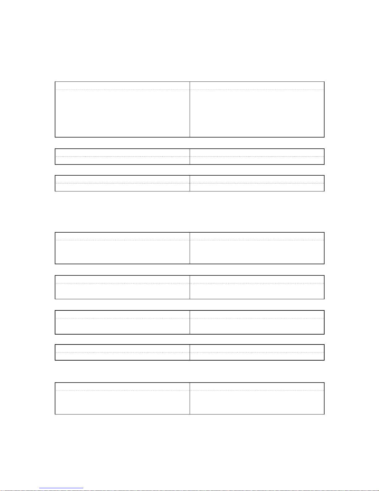
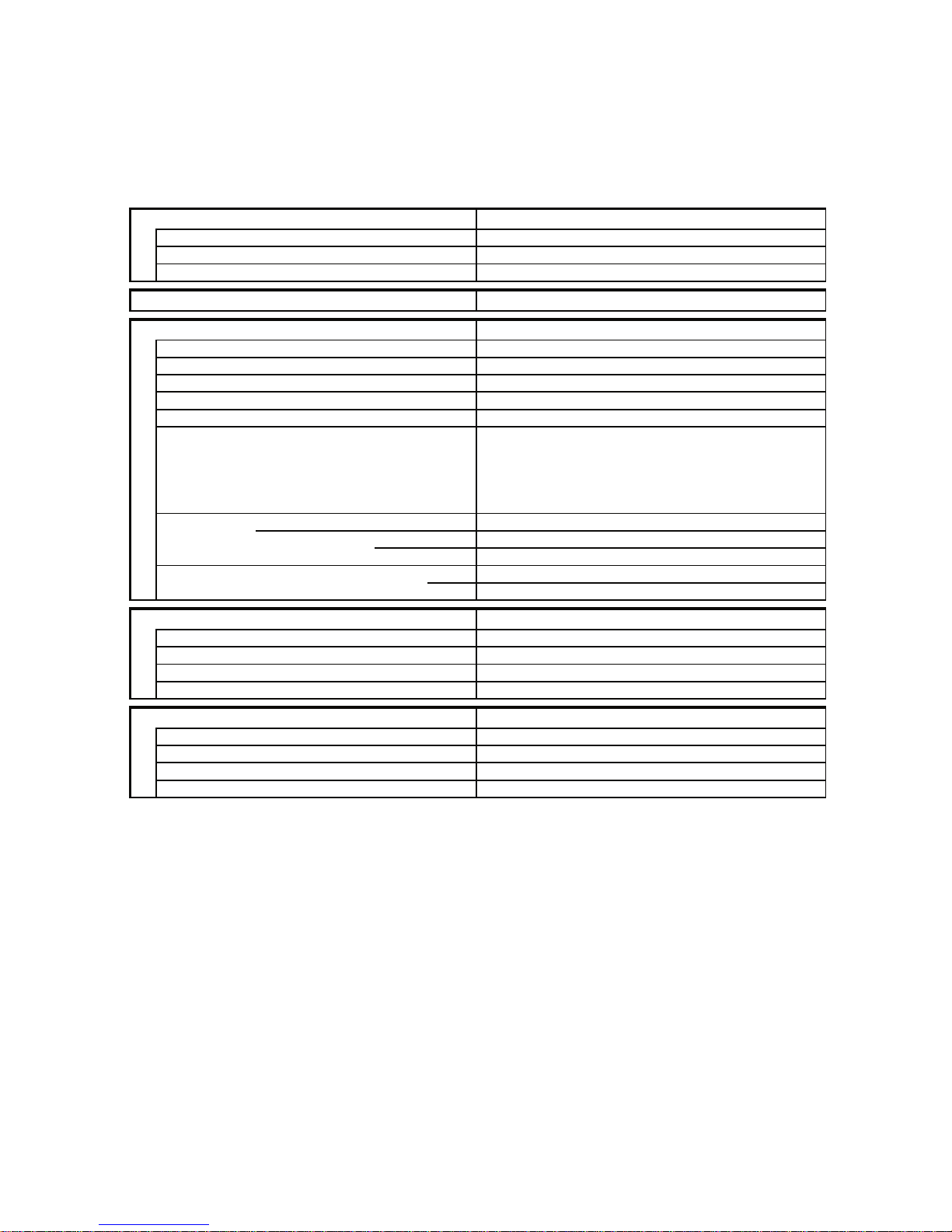
2-3. Other Component Specifications
8
<Only for SAP-C121 models>
Thermostat (Fan Speed Control 23S) MQT5S
Switching temp. °C
high ➞ LOW 28.5°C ± 1.5
low ➞ HIGH 31.5°C ± 2
Contact rating AC 220V, 3A
<Only for SAP-C121 models>
PTC Thermistor (TH) TDK 101YV
Resistance Ω (at 25°C) 100 ± 20%
4-way Valve (20S) LB81012 (Coil), VK1100B (Valve)
Coil rating AC 220/240V, 50/60Hz, 6W
Coil resistance Ω (at 20°C) 3,030 ± 7%
Thermostat (Defrost thermo. 23D) TRS02-12MSR
Operating temp. °C ON 12 ± 2
Diff. 8 deg. below
Power Relay (PR) DFU24D1-F (M)
Coil rating DC 24V
Coil resistance Ω (at 20°C) 650 ± 10%
Contact rating AC 250V, 20A
Outdoor Unit SAP–C91AHA
SAP–C121AHA
Thermistor (Room sensor) DTN-TKS128B
Resistance kΩ 25°C 5.0 ± 3%
Thermistor (Coil sensor) DTN-TKS131B
Resistance kΩ 0°C 15.0 ± 2%
Transformer (TR) ATR-J105
Rating Primary AC 230V, 50/60Hz
Secondary 19V, 0.526A
Capacity 10VA
Coil resistance Ω (at 21°C) Primary (WHT – WHT): 205 ± 10%
Secondary (BRN – BRN): 2.0 ± 10%
Thermal cut-off temp. 150°C
Indoor Unit SAP–K91AHA
SAP–K121AHA
9
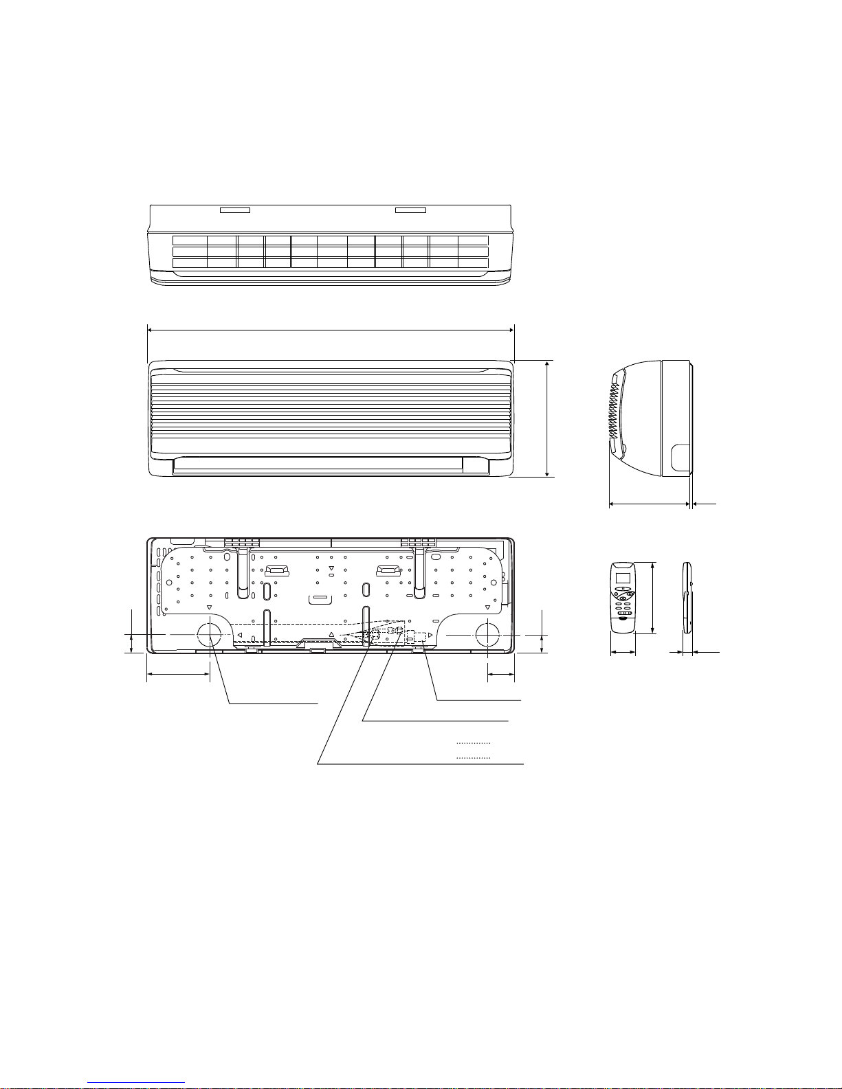
3. DIMENSIONAL DATA
Indoor Unit SAP–K91AHA
SAP–K121AHA
790
250
174 (3)
Narrow tube ø6.35 (1/4")
Drain hose ø18
58.5
132
41.0
41.0
Center of tubing
hole (2 places)
Remote control unit
172
61 23
Wide tube ø9.52 (3/8")
Wide tube ø12.7 (1/2")
K91
K121
Unit : mm
10
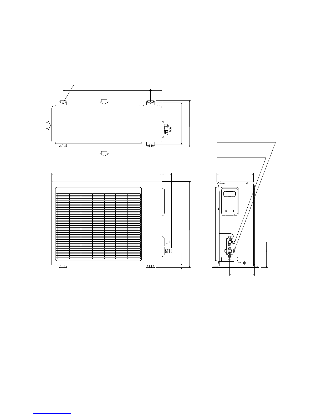
Outdoor Unit SAP–C91AHA
680 58
530
15
225
Narrow tube service valve
ø6.35 (1/4")
Wide tube service valve
ø9.52 (3/8")
150
103 55
538
2 – ø12 holes
71
286
260
Air intake
Air discharge
Unit : mm
11
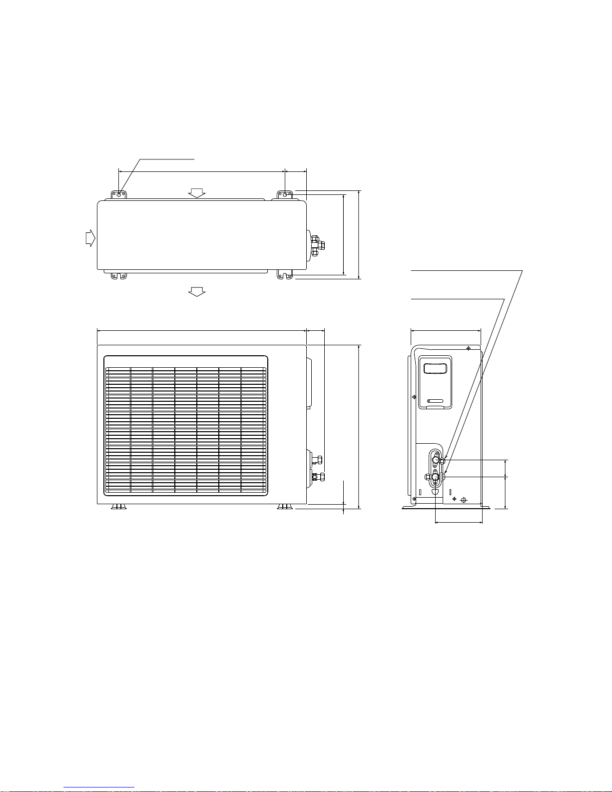
Outdoor Unit SAP–C121AHA
680 71
530
15
225
Narrow tube service valve
ø6.35 (1/4")
Wide tube service valve
ø12.7 (1/2")
150
103 55
538
2 – ø12 holes
71
286
260
Air intake
Air discharge
Unit : mm
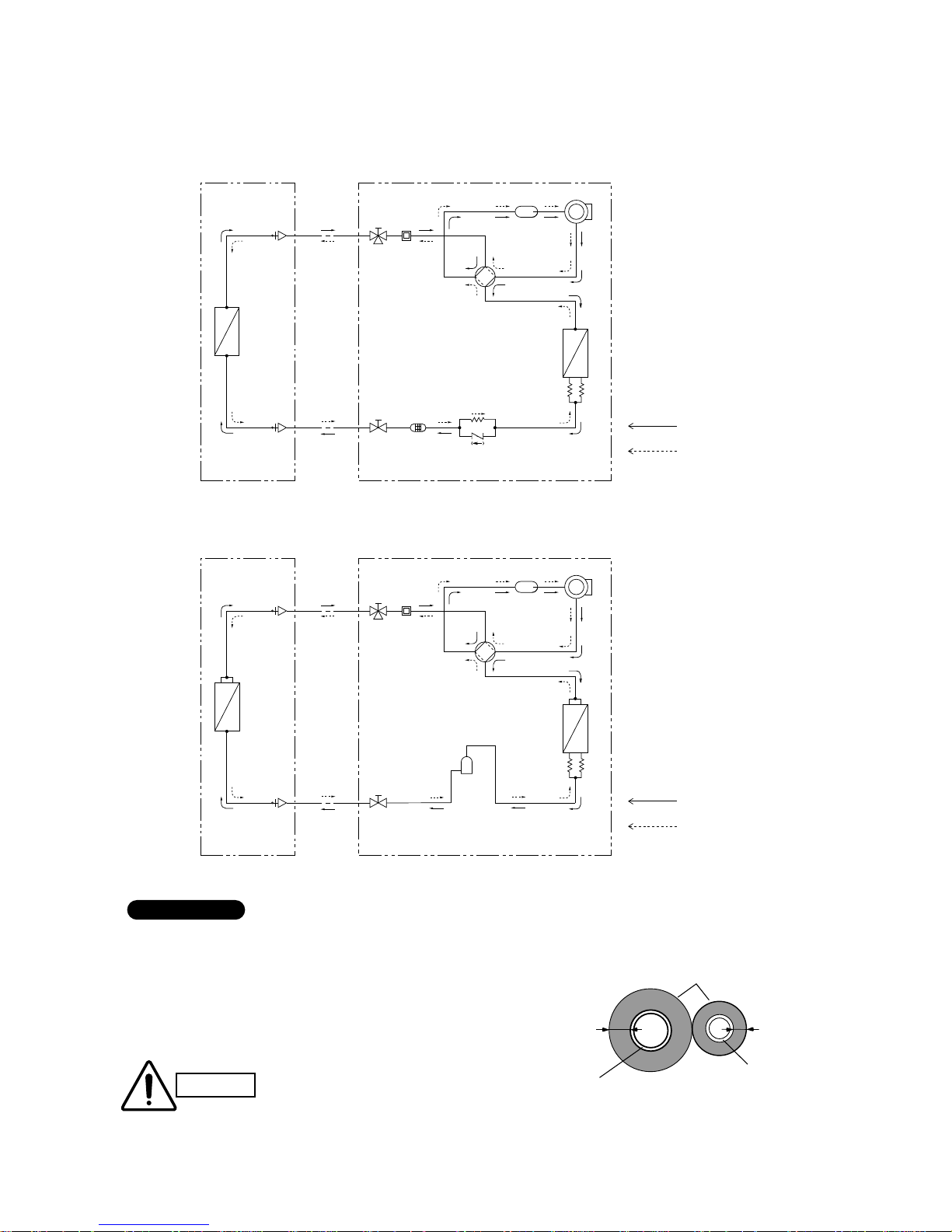
4. REFRIGERANT FLOW DIAGRAM
12
Insulation of Refrigerant Tubing
Because capillary tubing is used in the outdoor unit, both the
wide and narrow tubes of this air conditioner become cold. To
prevent heat loss and wet floors due to dripping of
condensation, both tubes must be well insulated with a
proper insulation material. The thickness of the insulation
should be a min. 8 mm.
After a tube has been insulated,
never try to bend it into a narrow
curve because it can cause the tube
to break or crack.
IMPORTANT
CAUTION
Wide tube
Thickness:
Min. 8 mm
Insulation
Narrow tube
Thickness:
Min. 8 mm
Compressor
4-way
valve
Accumulator
Wide tube
service
valve
Wide tube
O.D.
ø9.52 mm
(3/8 ")
Narrow
tube
service
valve
Narrow tube
O.D.
ø6.35 mm
(1/4")
Heat exchanger
Heat exchanger
Muffler
Cooling cycle
Heating cycle
Strainer
Indoor unit Outdoor unit
Capillary tube
(for heating)
Check
valve
Capillary tubes
(both for heating
and cooling)
Indoor Unit SAP–K91AHA Outdoor Unit SAP–C91AHA
Compressor
4-way
valve
Accumulator
Wide tube
service
valve
Wide tube
O.D.
ø12.7 mm
(1/2 ")
Narrow
tube
service
valve
Narrow tube
O.D.
ø6.35 mm
(1/4")
Heat exchanger
Heat exchanger
Muffler
Cooling cycle
Heating cycle
Indoor unit Outdoor unit
Capillary tubes
(both for heating
and cooling)
Receiver
tank
Indoor Unit SAP–K121AHA Outdoor Unit SAP–C121AHA
5. PERFORMANCE DATA
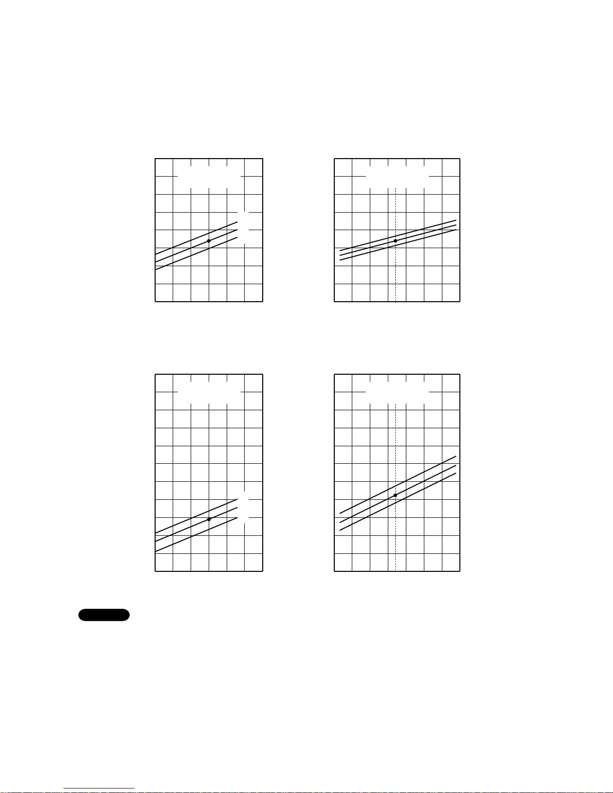
5-1. Performance charts
13
Indoor inlet air
D.B. temp. (°C)
■ Cooling Characteristics ■ Heating Characteristics
9
8
7
6
5
4
3
2
1
25 30 35 40 45 50
Outdoor inlet air D.B. temp. (°C)
Operating current (A)
8
7
6
5
4
3
2
1
–5 0 5 10 15 20
Outdoor inlet air D.B. temp. (°C)
Operating current (A)
25
9
32
27
21
27
20
15
27
20
15
Indoor inlet air
D.B. temp. (°C)
Indoor inlet air
D.B. temp. (°C)
Indoor inlet air
D.B. temp. (°C)
Outdoor inlet air D.B. temp. (°C)
25 30 35 40 45 50
Low pressure at wide tube serveice valve MPa (kgf/cm
2
G)
1.38 (13)
1.28 (12)
1.18 (11)
1.08 (10)
0.98 ( 9 )
0.89 ( 8 )
0.79 ( 7 )
0.69 ( 6 )
0.59 ( 5 )
0.49 ( 4 )
0.39 ( 3 )
1.47 (14)
Outdoor inlet air D.B. temp. (
°C)
–5 0 5 10 15 20 25
High pressure at wide tube serveice valve MPa (kgf/cm
2
G)
3.24 (32)
2.95 (30)
2.85 (28)
2.65 (26)
2.46 (24)
2.26 (22)
2.06 (20)
1.87 (18)
1.67 (16)
1.47 (14)
1.28 (12)
1.08 (10)
32
27
21
● ...... Points of Rating condition
Black dots in above charts indicate the following rating conditions.
Cooling: Indoor air temperature 27°C D.B./19°C W.B. Heating: Indoor air temperature 20°C D.B.
Outdoor air temperature 35°C D.B./24°C W.B. Outdoor air temperature 7°C D.B./6°C W.B.
NOTE
Indoor Unit SAP–K91AHA
Outdoor Unit SAP–C91AHA
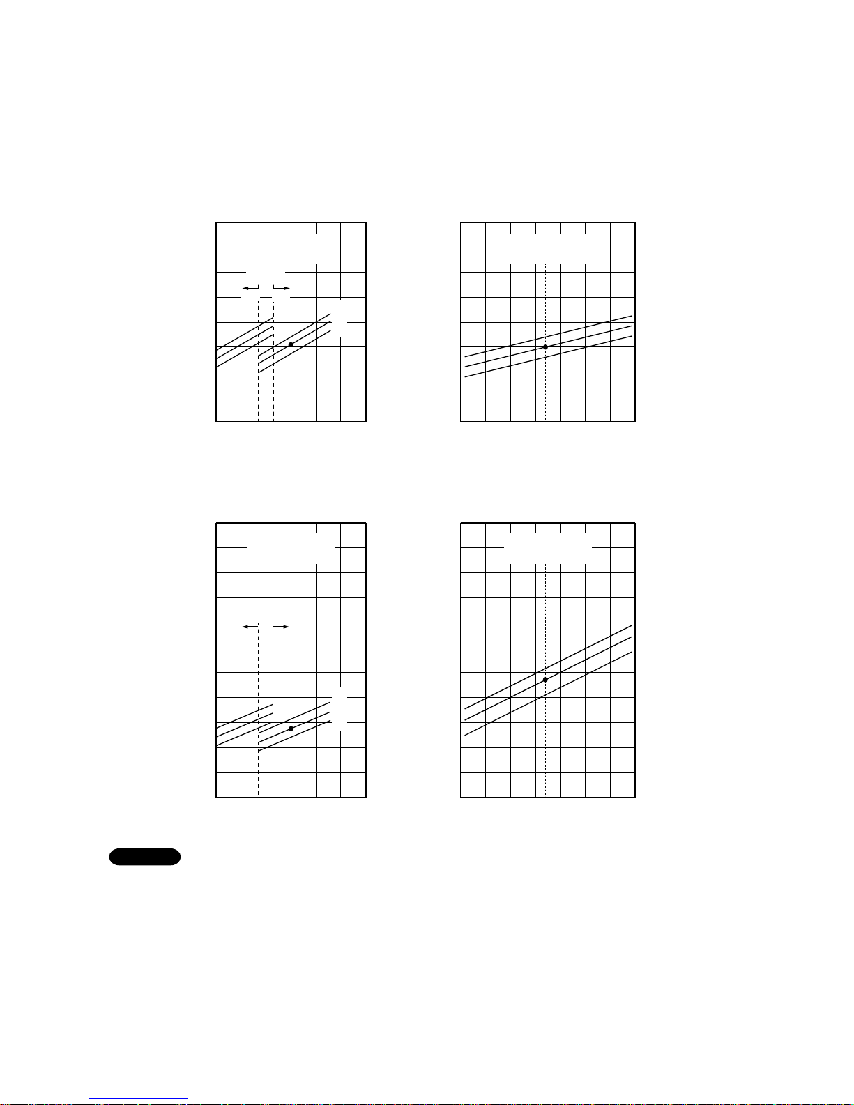
14
Indoor inlet air
D.B. temp. (°C)
■ Cooling Characteristics ■ Heating Characteristics
11
10
9
8
7
6
5
4
3
25 30 35 40 45 50
Outdoor inlet air D.B. temp. (°C)
Operating current (A)
10
9
8
7
6
5
4
3
–5 0 5 10 15 20
Outdoor inlet air D.B. temp. (°C)
Operating current (A)
25
11
27
20
15
27
20
15
Indoor inlet air
D.B. temp. (°C)
HighLow
Outdoor
fan speed
HighLow
Outdoor
fan speed
32
27
21
32
27
21
Indoor inlet air
D.B. temp. (°C)
Indoor inlet air
D.B. temp. (°C)
Outdoor inlet air D.B. temp. (°C)
–5 0 5 10 15 20 25
High pressure at wide tube serveice valve MPa (kgf/cm
2
G)
3.24 (32)
2.95 (30)
2.85 (28)
2.65 (26)
2.46 (24)
2.26 (22)
2.06 (20)
1.87 (18)
1.67 (16)
1.47 (14)
1.28 (12)
1.08 (10)
Outdoor inlet air D.B. temp. (
°C)
25 30 35 40 45 50
Low pressure at wide tube serveice valve MPa (kgf/cm
2
G)
1.38 (13)
1.28 (12)
1.18 (11)
1.08 (10)
0.98 ( 9 )
0.89 ( 8 )
0.79 ( 7 )
0.69 ( 6 )
0.59 ( 5 )
0.49 ( 4 )
0.39 ( 3 )
1.47 (14)
● ...... Points of Rating condition
Black dots in above charts indicate the following rating conditions.
Cooling: Indoor air temperature 27°C D.B./19°C W.B. Heating: Indoor air temperature 20°C D.B.
Outdoor air temperature 35°C D.B./24°C W.B. Outdoor air temperature 7°C D.B./6°C W.B.
NOTE
Indoor Unit SAP–K121AHA
Outdoor Unit SAP–C121AHA
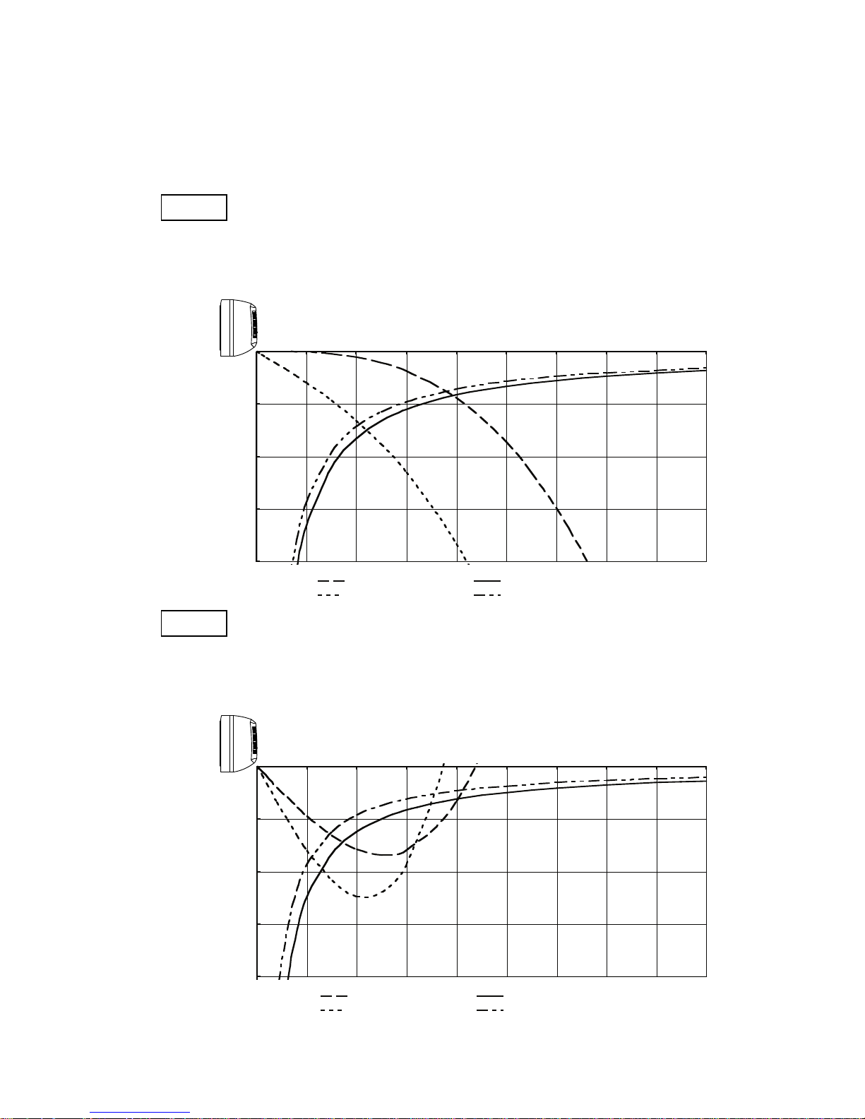
5-2. Air Throw Distance Chart
Horizontal distance (m)
Axis air verocity (m/s)
Vertical distance (m)
Room air temp. : 20°C
Fan speed : High
Heating
Horizontal distance (m)
Axis air verocity (m/s)
Vertical distance (m)
Room air temp. : 27°C
Fan speed : High
Cooling
0
1
2
3
4
0 1 2 3 4 5 6 7 8 9
: Flap angle 0° , : Axis air velocity 0°
: Flap angle 30°, : Axis air velocity 30°
0
1
2
3
4
0 1 2 3 4 5 6 7 8 9
: Flap angle 45° , : Axis air velocity 45°
: Flap angle 60° , : Axis air velocity 60°
15
Indoor Unit SAP–K91AHA

16
Horizontal distance (m)
Axis air verocity (m/s)
Vertical distance (m)
Room air temp. : 20°C
Fan speed : High
Heating
Horizontal distance (m)
Axis air verocity (m/s)
Vertical distance (m)
Room air temp. : 27°C
Fan speed : High
Cooling
0
1
2
3
4
0 1 2 3 4 5 6 7 8 9
: Flap angle 0° , : Axis air velocity 0°
: Flap angle 30°, : Axis air velocity 30°
0
1
2
3
4
0 1 2 3 4 5 6 7 8 9
: Flap angle 45° , : Axis air velocity 45°
: Flap angle 60° , : Axis air velocity 60°
Indoor Unit SAP–K121AHA
17
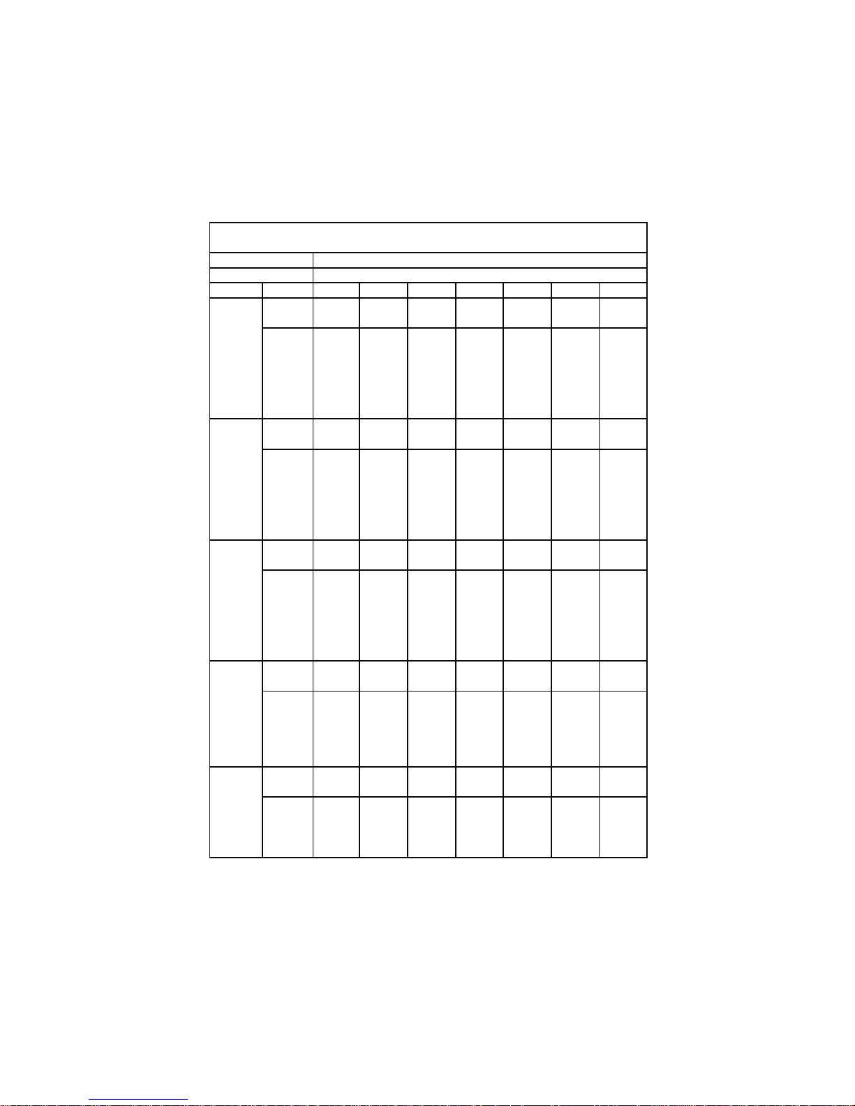
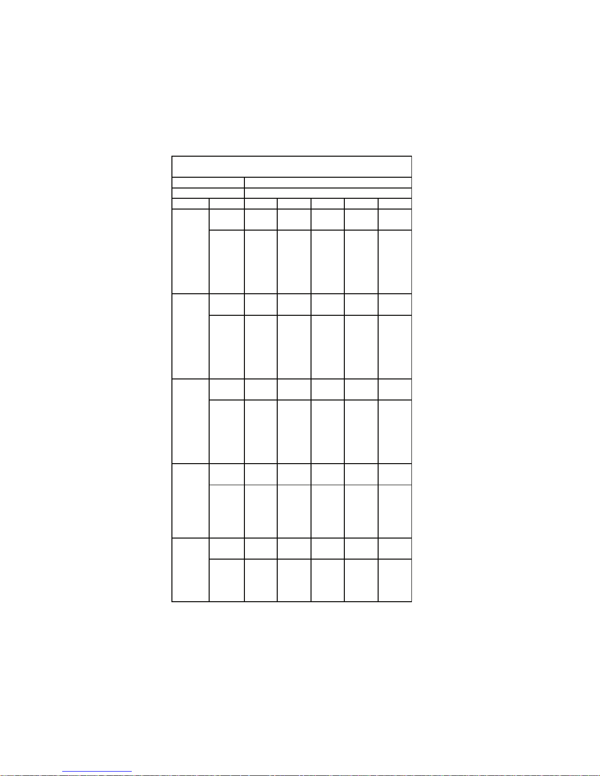
5-3. Cooling Capacity
Indoor Unit SAP–K91AHA
Outdoor Unit SAP–C91AHA
240V Single Phase 50Hz
RATING CAPACITY 2.50 kW
AIR FLOW RATE 430
m3/h
EVAPORATOR CONDENSER
ENT. TEMP. °C OUTDOOR AMBIENT TEMP. °C
W.B. D.B. 20 25 30 35 40 43
TC 2.52 2.41 2.30 2.19 2.06 1.89
CM 0.70 0.76 0.81 0.87 0.94 1.01
21 SHC 1.71 1.65 1.59 1.54 1.47 1.40
15 23 SHC 1.92 1.86 1.80 1.75 1.68 1.61
25 SHC 2.13 2.07 2.01 1.96 1.89 1.82
27 SHC 2.34 2.28 2.22 2.17 2.06 1.89
29 SHC 2.52 2.41 2.30 2.19 2.06 1.89
31 SHC 2.52 2.41 2.30 2.19 2.06 1.89
TC 2.70 2.59 2.47 2.35 2.21 2.03
CM 0.72 0.78 0.83 0.89 0.96 1.03
21 SHC 1.49 1.43 1.38 1.32 1.26 1.18
17 23 SHC 1.70 1.64 1.59 1.53 1.47 1.39
25 SHC 1.91 1.85 1.80 1.74 1.68 1.60
27 SHC 2.12 2.06 2.01 1.95 1.89 1.81
29 SHC 2.33 2.27 2.22 2.16 2.10 2.02
31 SHC 2.54 2.48 2.43 2.35 2.21 2.03
TC 2.88 2.75 2.63 # 2.50 2.35 2.16
CM 0.74 0.80 0.86 0.92 0.99 1.06
21 SHC 1.26 1.21 1.15 1.10 1.03 0.96
19 23 SHC 1.47 1.42 1.36 1.31 1.24 1.17
25 SHC 1.68 1.63 1.57 1.52 1.45 1.38
27 SHC 1.89 1.84 1.78 1.73 1.66 1.59
29 SHC 2.10 2.05 1.99 1.94 1.87 1.80
31 SHC 2.31 2.26 2.20 2.15 2.08 2.01
TC 3.05 2.92 2.78 2.65 2.49 2.29
CM 0.76 0.82 0.88 0.95 1.02 1.09
23 SHC 1.24 1.19 1.13 1.08 1.02 0.94
21 25 SHC 1.45 1.40 1.34 1.29 1.23 1.15
27 SHC 1.66 1.61 1.55 1.50 1.44 1.36
29 SHC 1.87 1.82 1.76 1.71 1.65 1.57
31 SHC 2.08 2.03 1.97 1.92 1.86 1.78
TC 3.23 3.09 2.95 2.78 2.60 2.42
CM 0.78 0.84 0.90 0.97 1.05 1.12
23 25 SHC 1.21 1.16 1.10 1.04 0.98 0.91
27 SHC 1.42 1.37 1.31 1.25 1.19 1.12
29 SHC 1.63 1.58 1.52 1.46 1.40 1.33
31 SHC 1.84 1.79 1.73 1.67 1.61 1.54
TC : Total Cooling Capacity (kW)
SHC : Sensible Heat Capacity (kW)
CM : Compressor Input (kW)
Rating conditions (#Mark) are
Outdoor Ambient Temp. 35°C D.B.
Indoor Unit Entering Air Temp. 27°C D.B. / 19°C W.B.
18
Indoor Unit SAP–K121AHA
Outdoor Unit SAP–C121AHA
240V Single Phase 50Hz
RATING CAPACITY 3.20 kW
AIR FLOW RATE 470
m3/h
EVAPORATOR CONDENSER
ENT. TEMP. °C OUTDOOR AMBIENT TEMP. °C
W.B. D.B. 30 35 40 43
TC 2.94 2.80 2.63 2.42
CM 1.10 1.18 1.26 1.35
21 SHC 1.96 1.89 1.80 1.69
15 23 SHC 2.18 2.11 2.02 1.92
25 SHC 2.41 2.34 2.25 2.14
27 SHC 2.64 2.56 2.47 2.37
29 SHC 2.86 2.79 2.63 2.42
31 SHC 2.94 2.80 2.63 2.42
TC 3.16 3.01 2.83 2.60
CM 1.13 1.21 1.29 1.38
21 SHC 1.73 1.65 1.57 1.46
17 23 SHC 1.95 1.88 1.79 1.68
25 SHC 2.18 2.11 2.02 1.91
27 SHC 2.41 2.33 2.24 2.14
29 SHC 2.63 2.56 2.47 2.36
31 SHC 2.86 2.78 2.69 2.59
TC 3.36 # 3.20 3.01 2.77
CM 1.17 1.25 1.33 1.42
21 SHC 1.49 1.41 1.32 1.22
19 23 SHC 1.71 1.64 1.55 1.44
25 SHC 1.94 1.86 1.77 1.67
27 SHC 2.16 2.09 2.00 1.89
29 SHC 2.39 2.31 2.22 2.12
31 SHC 2.61 2.54 2.45 2.34
TC 3.56 3.39 3.19 2.93
CM 1.20 1.29 1.37 1.46
23 SHC 1.46 1.39 1.30 1.20
21 25 SHC 1.69 1.61 1.53 1.42
27 SHC 1.91 1.84 1.75 1.65
29 SHC 2.14 2.06 1.98 1.87
31 SHC 2.36 2.29 2.20 2.10
TC 3.77 3.56 3.33 3.10
CM 1.23 1.32 1.41 1.50
23 25 SHC 1.42 1.34 1.25 1.16
27 SHC 1.65 1.56 1.47 1.39
29 SHC 1.87 1.79 1.70 1.61
31 SHC 2.10 2.01 1.92 1.84
TC : Total Cooling Capacity (kW)
SHC : Sensible Heat Capacity (kW)
CM : Compressor Input (kW)
Rating conditions (#Mark) are
Outdoor Ambient Temp. 35°C D.B.
Indoor Unit Entering Air Temp. 27°C D.B. / 19°C W.B.
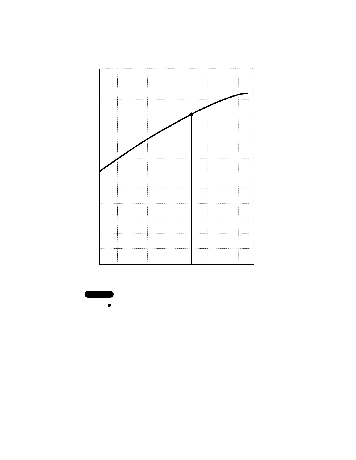
5-4. Heating Capacity
–5 0 5
7
10 15
Outdoor temperature (°C D.B.)
0
10
20
30
40
50
60
70
80
90
100
110
120
Heating capacity ratio (%)
NOTE
1) … Point of Rating condition
Black dot in the chart indicate the following rating condition.
Indoor : 20°C D.B.
Outdoor : 7°C D.B. / 6°C W.B.
2) Above characteristics indicate instantaneous operation, which does not take into
account defrost operation.
3) Fan speed : High
4) Because this air conditioner heats a room by drawing in the heat of the outside
air (heat pump system), the heating efficiency will fall off when the outdoor
temperature is very low. If sufficient heat cannot be obtained with this air
conditioner, use another heating appliance in conjunction with it.
–8
19

20
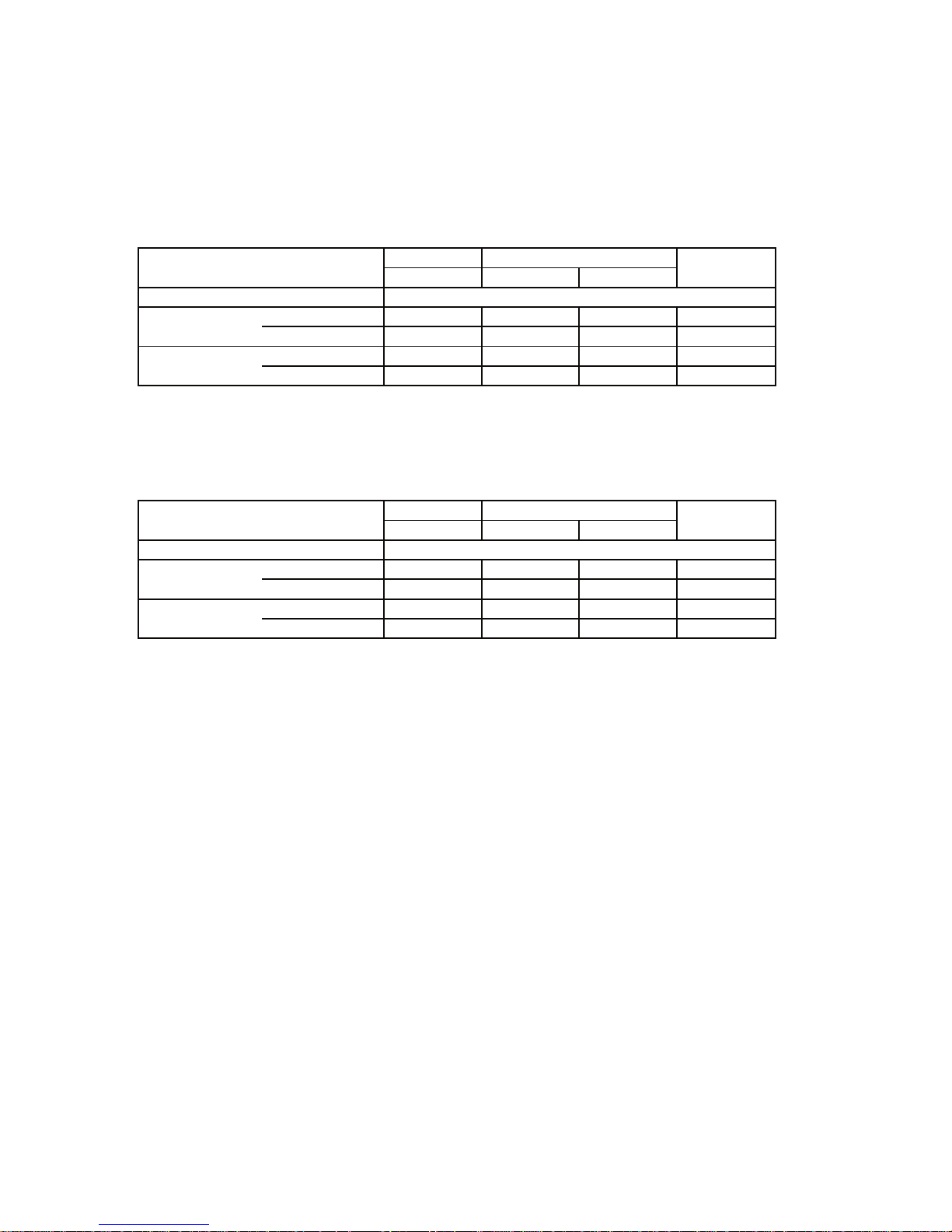
6. ELECTRICAL DATA
6-1. Electrical Characteristics
COOLING
Indoor Unit Outdoor Unit Complete Unit
Fan Motor Fan Motor Compressor
Performance at 240V Single phase 50Hz
Rating Conditions Running Amps. A 0.18 0.25 3.97 4.4
Power Input kW 0.040 0.060 0.920 1.02
Full Load Conditions Running Amps. A 0.18 0.25 4.87 5.3
Power Input kW 0.040 0.060 1.120 1.22
Rating Conditions : Indoor Air Temperature 27°C D.B. / 19°C W.B.
Outdoor Air Temperature 35°C D.B.
Full Load Conditions : Indoor Air Temperature 32°C D.B. / 23°C W.B.
Outdoor Air Temperature 43°C D.B.
HEATING
Indoor Unit Outdoor Unit Complete Unit
Fan Motor Fan Motor Compressor
Performance at 240V Single phase 50Hz
Rating Conditions Running Amps. A 0.18 0.25 3.97 4.4
Power Input kW 0.040 0.060 0.920 1.02
Full Load Conditions Running Amps. A 0.18 0.25 4.97 5.4
Power Input kW 0.040 0.060 1.110 1.21
Rating Conditions : Indoor Air Temperature 20°C D.B.
Outdoor Air Temperature 7°C D.B. / 6°C W.B.
Full Load Conditions : Indoor Air Temperature 27°C D.B.
Outdoor Air Temperature 24°C D.B. / 18°C W.B.
Indoor Unit SAP–K91AHA
Outdoor Unit SAP–C91AHA
21
COOLING
Indoor Unit Outdoor Unit Complete Unit
Fan Motor Fan Motor Compressor
Performance at 240V Single phase 50Hz
Rating Conditions Running Amps. A 0.18 0.25 5.67 6.1
Power Input kW 0.040 0.060 1.250 1.35
Full Load Conditions Running Amps. A 0.18 0.25 6.77 7.2
Power Input kW 0.040 0.060 1.500 1.60
Rating Conditions : Indoor Air Temperature 27°C D.B. / 19°C W.B.
Outdoor Air Temperature 35°C D.B.
Full Load Conditions : Indoor Air Temperature 32°C D.B. / 23°C W.B.
Outdoor Air Temperature 43°C D.B.
HEATING
Indoor Unit Outdoor Unit Complete Unit
Fan Motor Fan Motor Compressor
Performance at 240V Single phase 50Hz
Rating Conditions Running Amps. A 0.18 0.25 5.57 6.0
Power Input kW 0.040 0.060 1.220 1.32
Full Load Conditions Running Amps. A 0.18 0.25 6.67 7.1
Power Input kW 0.040 0.060 1.450 1.55
Rating Conditions : Indoor Air Temperature 20°C D.B.
Outdoor Air Temperature 7°C D.B. / 6°C W.B.
Full Load Conditions : Indoor Air Temperature 27°C D.B.
Outdoor Air Temperature 24°C D.B. / 18°C W.B.
Indoor Unit SAP–K121AHA
Outdoor Unit SAP–C121AHA
 Loading...