

Sanyo SA–183A Technical & Service Manual
TECHNICAL & SERVICE MANUAL
SA–183A
FILE NO.
REFERENCE NO. SM700514
WINDOW TYPE AIR CONDITIONER
SA–183A
Model No. Product Code No.
SA-183A 1 851 006 96
Destination
Australia
IMPORTANT!
Please Read Before Starting
This air conditioner meets strict safety and operating
standards. As the installer or service person, it is an
important part of your job to install or service the system
so it operates safely and efficiently.
For safe installation and trouble-free operation, you
must:
• Carefully read the INSTRUCTION MANUAL and
INSTALLATION INSTRUCTIONS attached to each air
conditioner before beginning.
• Follow each installation or repair step exactly as shown.
• Observe all local, state, and national electrical codes.
• Pay close attention to all warning and caution notices
given in this manual.
This symbol refers to a hazard or
unsafe practice which can result in
severe personal injury or death.
This symbol refers to a hazard or
unsafe practice which can result in
personal injury or product or property
damage.
If Necessary, Get Help
These instructions are all you need for most installation
sites and maintenance conditions. If you require help for a
special problem, contact our sales/service outlet or your
certified dealer for additional instructions.
SPECIAL PRECAUTIONS
When Wiring
ELECTRICAL SHOCK CAN CAUSE SEVERE
PERSONAL INJURY OR DEATH. ONLY A
QUALIFIED, EXPERIENCED ELECTRICIAN
SHOULD ATTEMPT TO WIRE THIS SYSTEM.
• All wiring must conform to local electrical codes.
• Each unit must be properly grounded with a ground (or
earth) wire or through the supply wiring.
• DO NOT, under any circumstances, cut or remove the
third (ground) prong from the power cord plug.
• DO NOT use an adapter Plug or extension cord.
• DO NOT use a damaged power cord, plug, or wall outlet.
Replace them immediately.
• DO NOT change the internal wiring or any part of the
system.
• DO NOT turn the air conditioner on and off by plugging
and unplugging. Use the Operation switch.
When Transporting
Be careful when picking up and moving the air conditioner.
Get a partner to help, and bend your knees when lifting to
reduce strain on your back. Sharp edges or thin aluminum
fins on the air conditioner can cut your fingers.
WARNING
When Installing
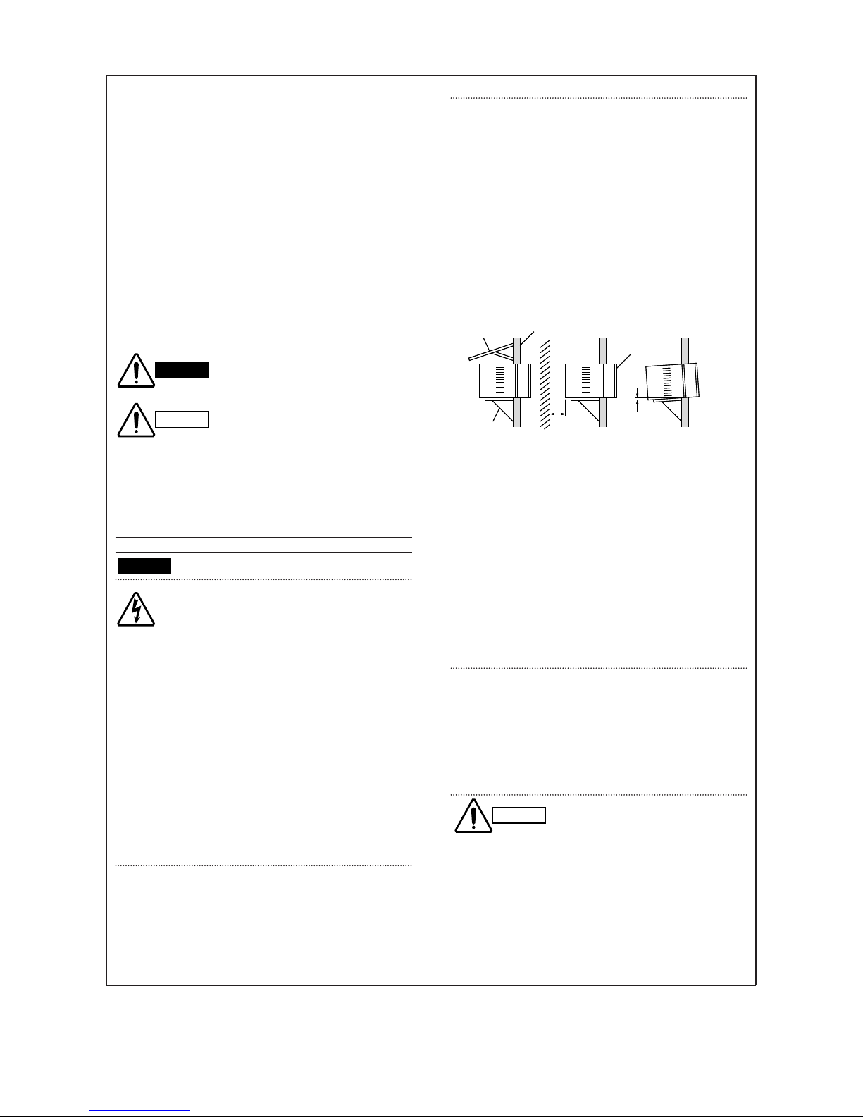
Place of Installation
• If possible, install the unit in a shady location. If the site
is exposed to the sun, you should provide a sun screen
as shown in Fig. a.
• Install it at a spot where optimum cooling circulation can
be obtained. No chairs or other obstructions are allowed
in front of the air conditioner.
• The back of the air conditioner must extend outside.
(Be sure the right and left intake vents are not obstructed
by walls or windows.)
• Keep enough space from any outside obstruction (wall,
bush, etc.).
• To provide water drainage, the unit must be tilted at a
downward angle 0.5 to 1 cm to the outside.
• While installing the air conditioner, be sure to loosen the
compressor locking nuts to avoid abnormal noise and
vibration. (NOTE: Locking nuts are not provided on some
models.)
• As a safety measure, it is recommended that two people
install the unit: one to hold and balance the unit — the
other to lower the window frame to secure the unit.
• Hold the unit securely, and be careful to not drop the
cabinet or any parts if the air conditioner is being
installed on an upper floor of a multistory building.
When Servicing
• Turn the power OFF at the main power box (mains)
before opening the unit to check or repair electrical parts
and wiring.
• Keep fingers and clothing away from any moving parts.
• Clean up the site after you finish, remembering to check
that no metal scraps or bits of tools have been left inside
the unit being serviced.
Others
• Ventilate any enclosed areas when installing or testing
the refrigeration system. Escaped refrigerant gas, on
contact with fire or heat, can produce dangerously toxic
gas.
• Confirm upon completing installation that no refrigerant
gas is leaking. If escaped gas comes in contact with a
stove, gas water heater, electric room heater or other
heat source, it can produce dangerously toxic gas.
CAUTION
Outside
Wall
Enough space
from obstacle
or wall.
Tilt 0.5 to 1 cm
downward to outside.
Room
side
Front
grille
Wall
Screen
Tilt 0.5 to 1 cm
downward to outside.
Support
i
WARNING
CAUTION
Fig. a
HOW TO USE THIS MANUAL
This manual is designed to help service personnel to understand basic functions, operation and possible troubles
and their remedies on SANYO window type air conditioners. You can use this manual both as a reference to find
specific information about the capacity, construction of the unit, and as a source of information to help you set up
and maintain the air conditioner. Please use this manual to make your work easier, keep the air conditioner
functioning well, and keep your customer satisfied.
Please read IMPORTANT ! precautional information on the previous page before you start actual work.
SANYO WINDOW TYPE A/C NOMENCLATURE
SANYO window type air conditioner is identified by a model number. Cooling or heating capacity, electrical
information and special features included on the air conditioner are indicated on the model number.
ii
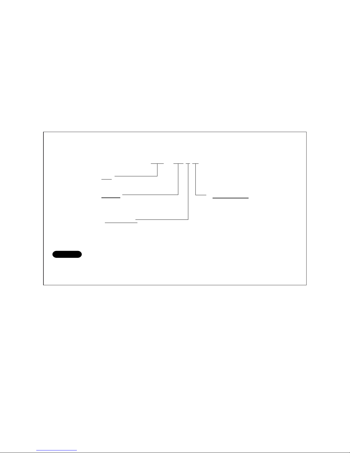
Example
S A – 1 8 3 A
Type
SA : SANYO window type A/C
Capacity
18 : 18,000 BTU/h class
Design Number
Special Features
A : Mechanical Control,
Cooling Model,
Side Air Discharge
NOTE
To identify the correct model number of your air conditioner, you must find the nameplate.

Table of Contents
Page
1. OPERATING RANGE ............................................................................................................................... 1
2. SPECIFICATIONS
2-1. Unit Specifications.......................................................................................................................... 2
2-2. Major Component Specifications.................................................................................................... 3
2-3. Other Component Specifications.................................................................................................... 4
3. DIMENSIONAL DATA............................................................................................................................... 5
4. REFRIGERANT FLOW DIAGRAM .......................................................................................................... 6
5. PERFORMANCE DATA
5-1. Cooling Capacity ........................................................................................................................... 7
6. ELECTRICAL DATA
6-1. Electric Characteristics .................................................................................................................. 8
6-2. Electric Wiring Diagram.................................................................................................................. 9
7. TROUBLESHOOTING
7-1. Check before and after troubleshooting ........................................................................................ 10
7-2. Air conditioner does not operate .................................................................................................... 11
7-3. Some part of air conditioner does not operate .............................................................................. 13
7-4. Air conditioner operates, but abnormalities are observed ............................................................. 15
8. CHECKING ELECTRICAL COMPONENTS
8-1. Measurement of Insulation Resistance .......................................................................................... 16
8-2. Checking Motor Capacitor.............................................................................................................. 17
8-3. Checking Fan Motor Winding ......................................................................................................... 17
8-4. Checking Compressor Motor Winding............................................................................................ 17
9. DISASSEMBLY PROCEDURES
9-1. Removing Front Grille .................................................................................................................... 18
9-2. Access and removal of Electrical Component Box ........................................................................ 18
9-3. Removing Cabinet ......................................................................................................................... 19
9-4. Removing Evaporator .................................................................................................................... 20
9-5. Removing Blower Wheel ............................................................................................................... 20
9-6. Removing Condenser .................................................................................................................... 20
9-7. Removing Propeller Fan ................................................................................................................ 21
9-8. Removing Fan Motor ..................................................................................................................... 21
Unit display and Control Panel ............................................................................................. 22
APPENDIX
iii

1
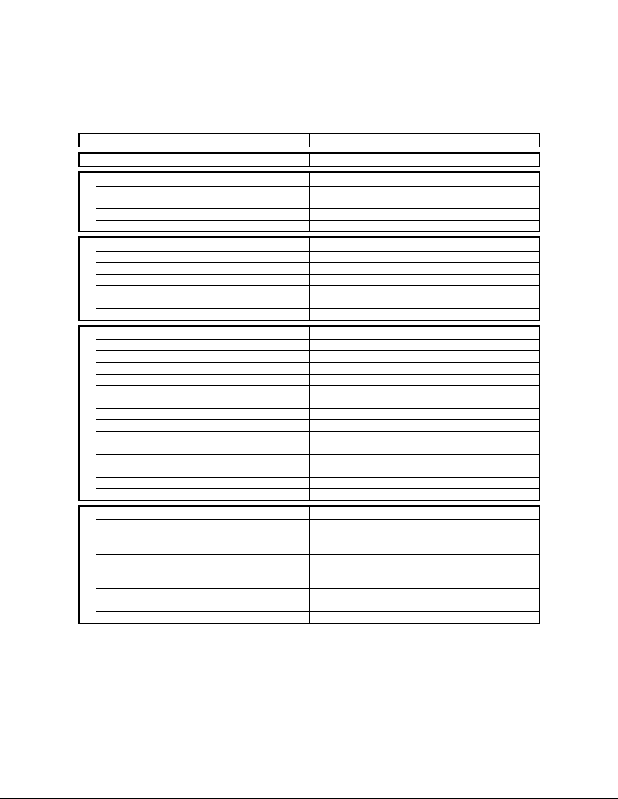
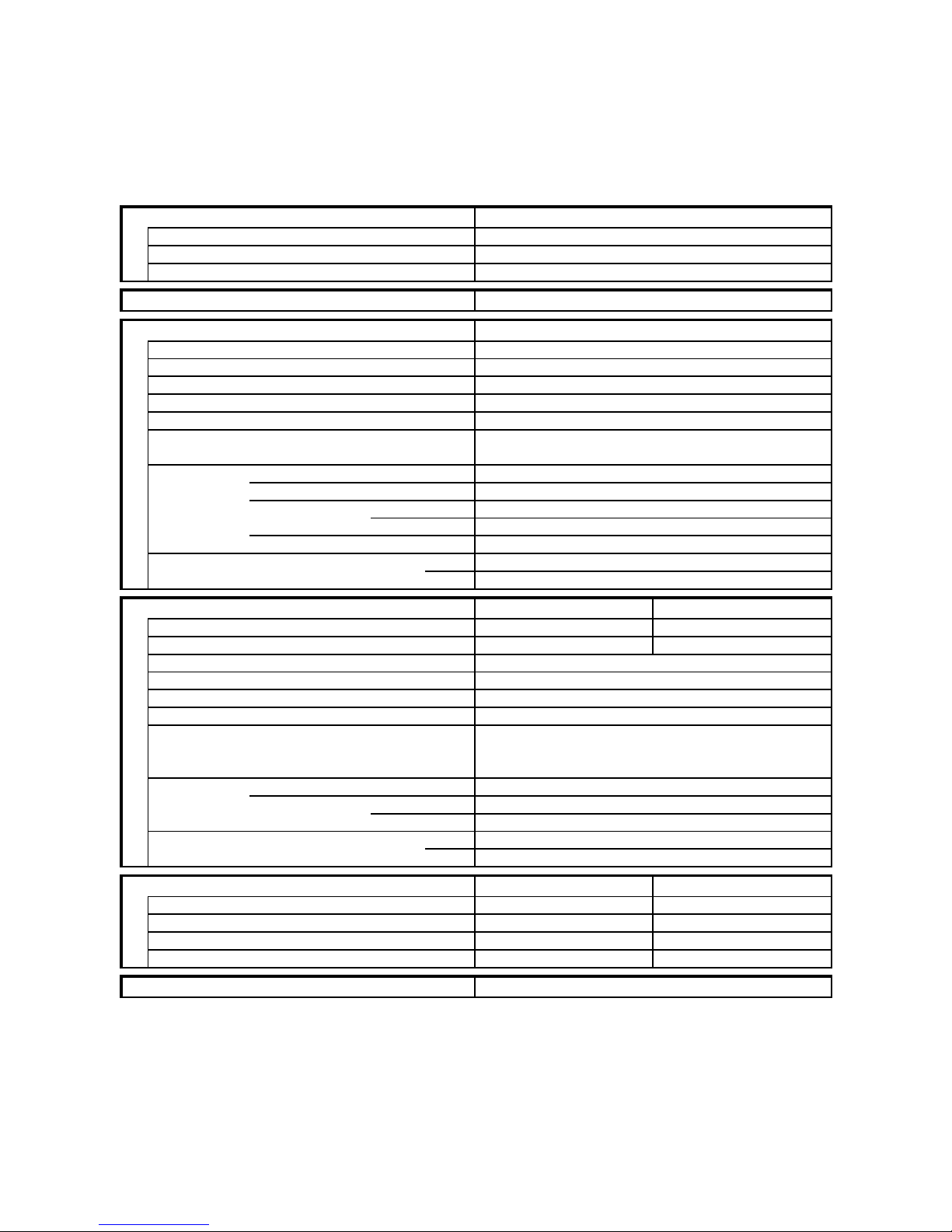
1. OPERATING RANGE
Temperature Indoor Air Intake Temp. Outdoor Air Intake Temp.
Cooling
Maximum 32°C D.B. / 23°C W.B. 43°C D.B.
Minimum 19°C D.B. / 14°C W.B. 19°C D.B.
2
2. SPECIFICATIONS
2-1. Unit Specifications
Model SA–183A
Power Source 240V Single phase 50Hz
Voltage rating 240 V
Performance Cooling
Capacity kW 5.30
BTU/h 18,100
Air circulation (High)
m3/h
850
Moisture removal (High) Liters/h 3.0
Electrical Rating Cooling
Available voltage range V 216 ~ 264
Running amperes A 9.3
Power input W 2,220
Power factor % 99
C.O.P. W/W 2.39
Starting amperes A 38
Features
Controls / Temperature control Mechanical / Thermostat
Control unit —
Timer —
Fan speeds 2
Airflow direction (Indoor) Horizontal Auto
Vertical Manual
Air filter / Air exhaust Washable / Yes
Compressor Rotary (Hermetic)
Refrigerant / Amount charged at shipment g R22 / 1,200
Refrigerant control Capillary tube
Operation sound Indoor : Hi / Lo dB-A 51 / 50
Outdoor : Hi / Lo dB-A 60 / 58
Slide-out chassis Yes
Accessories Wood screws
Dimensions & Weight
Unit dimensions Height mm 450
Width mm 670
Depth mm 646
Package dimensions Height mm 540
Width mm 740
Depth mm 720
Weight Net kg 65.0
Shipping kg 73.0
Shipping volume
m
3
0.29
DATA SUBJECT TO CHANGE WITHOUT NOTICE.
Remarks:
Rating conditions are:
Cooling : Indoor air temperature 27°C D.B. / 19°C W.B.
Outdoor air temperature 35°C D.B. / 24°C W.B.
3
2-2. Major Component Specifications
Model SA–183A
Controller PCB
Part No. —
Controls —
Control circuit fuse —
Remote Control Unit —
Compressor
Type Rotary (Hermetic)
Compressor model 2V36S225BUB
Source 220 ~ 240V Single phase 50Hz
Nominal output W 1,500
Compressor oil ... Amount cc ATMOS M60 or SUNISO-4GDID ... 650
Coil resistance (Ambient temp. 25°C) Ω C–R : 1.58
C–S : 2.71
Safety devices Type Internal protector
Overload relay —
Operating temp. Open °C Automatic opening
Close °C Automatic reclosing
Operating amp.(Ambient temp. 25°C) —
Run capacitor µF 50.0
VAC 400
Fan & Fan Motor Indoor Outdoor
Type Centrifugal Propeller
Dia. / Depth mm ø210 / D96 ø390 / D46.7
Fan motor model ... Q'ty FC6S-101E4P-A ... 1
Source 220 ~ 240V Single phase 50Hz
No. of poles ... rpm (220 V, High) 6 ... 910
Nominal output W 100
Coil resistance (Ambient temp. 20°C) Ω WHT-BRN : 64.6
WHT-YEL : 28.4
YEL-ORG(PNK) : 51.0
Safety devices Type Thermal protector
Operating temp. Open °C 130±5
Close °C Automatic reclosing
Run capacitor µF 4.5
VAC 440
Heat Exch. Coil
Coil Evaporator Condenser
Rows 3 3
Fin pitch mm 2.0 1.8
Face area
m
2
0.150 0.242
External Finish Acrylic baked-on enamel finish
DATA SUBJECT TO CHANGE WITHOUT NOTICE.
4
Model SA–183A
Auto Deflector Motor M16B
Rating AC 220-240V, 50/60Hz, 3 W, 4.2/5.0 rpm
Coil resistance kΩ (at 25°C)
11.15 ± 5%
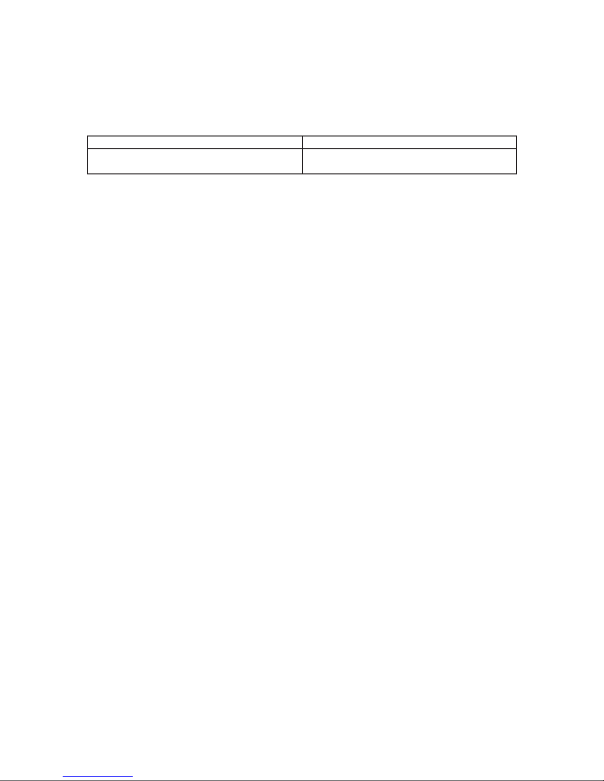
2-3. Other Component Specification
5
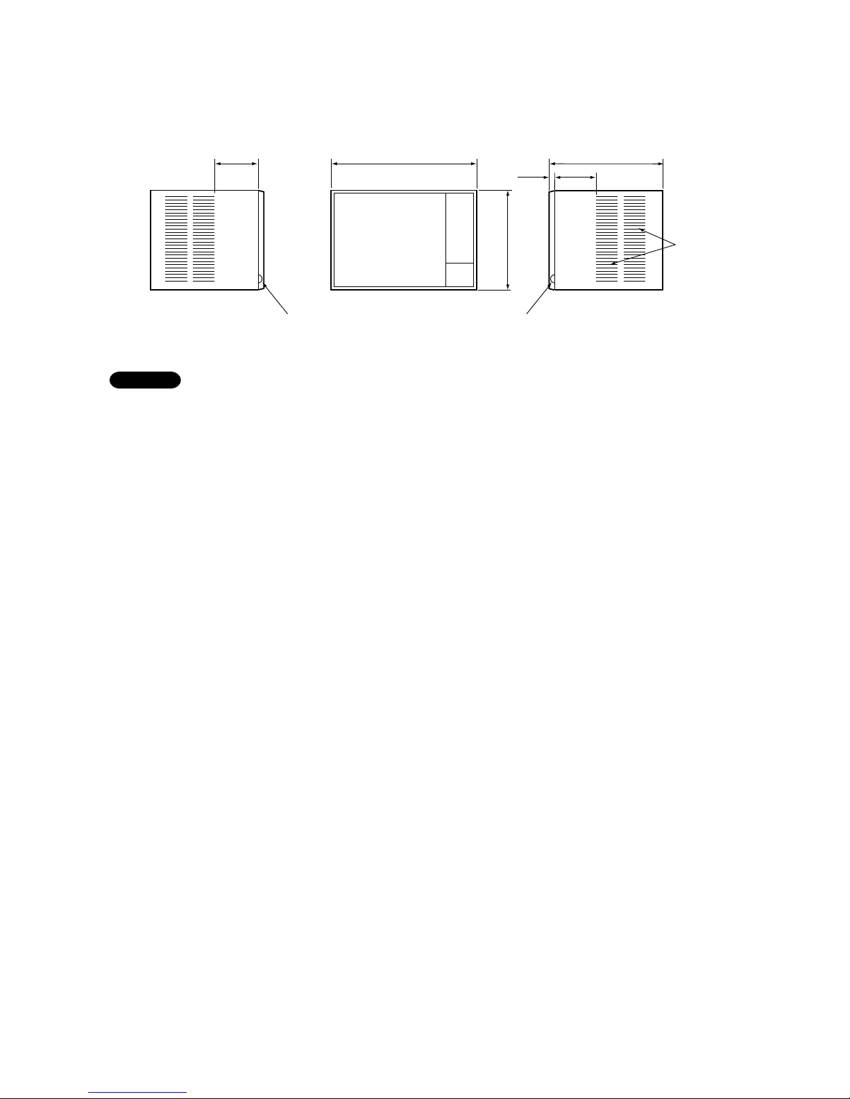
3. DIMENSIONAL DATA
Model SA–183A
Dimension with "✻" mark indicates the maximum allowable wall thickness required for ventilating the unit.
NOTE
✽ 236
670
450
35
276
646
Slits for
ventilation
Side view (L) Front view Side view (R)
Power code
outlet
Power code
outlet
Unit : mm
 Loading...