

Page 1
■ Parts supplied with remote controller
See Table 1.
■ Remote controller installation guidelines
• Mount the remote controller 1 to 1.5 meters off the
floor where it can sense the average temperature of
the room.
• Do not mount the remote controller in a place
exposed to direct sunlight or where it is exposed to
outside air such as near a window.
• Do not mount the remote controller behind a curtain
or other object so that it is separated from the air circulation of the room.
• Mount the remote controller inside the room being air
conditioned.
• The remote controller should be mounted on a wall or
other surface vertically.
Room temperature sensors are separately incorporated
in both the indoor unit and the remote controller. Either
sensor can be used to sense the room temperature. The
indoor unit sensor is usually used.
If you wish the remote controller to sense the room temperature, press the SENSOR button with a ballpoint pen
or tool with a small tip.
■ How to install the remote controller
<NOTE 1> Do not twist the remote controller wire
with the power cord, or run them in the
same metal conduit, because this may
cause a malfunction.
<NOTE 2> Install the remote controller away from all
sources of electrical noise.
<NOTE 3> Install a noise filter or take other appro-
priate action if electrical noise affects the
power supply circuit of the unit.
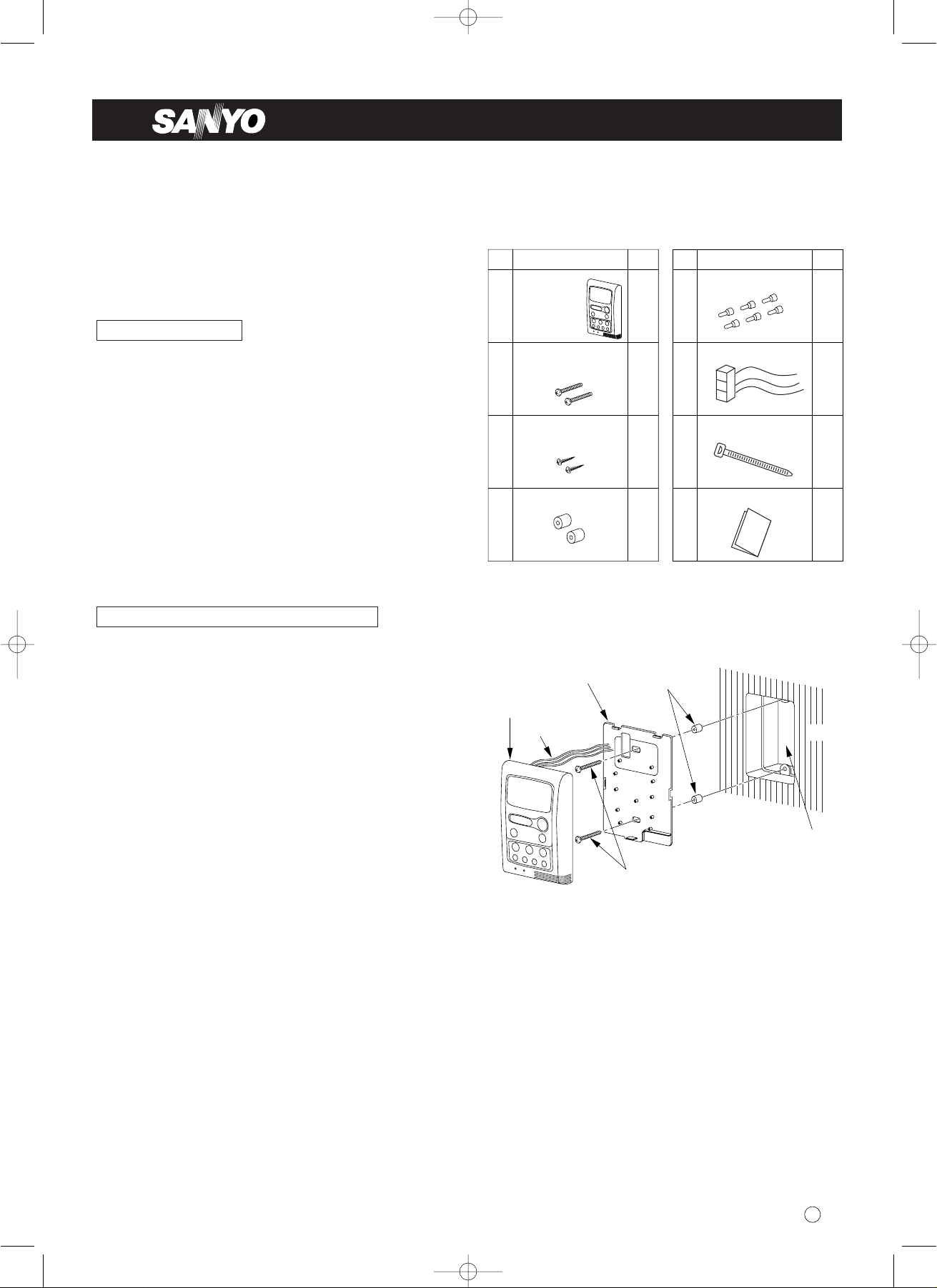
• Use an electric junction box (supplied locally) for
embedded mounting of the remote controller.
(See Fig. 1)
Switching the room temperature sensor
Installation location
Q’tyNo.
➀ 1
Supplied parts
Remote
controller
(comes with
200mm wire)
Machine screws
M4 × 25
Tapping screws
M4 × 25
2
2
➁
➂
Q’tyNo.
➃ 2
Supplied parts
Spacers
Wire joints
Harness
Clamper
Instruction manual
6
1
1
1
➄
➅
➆
➇
Ta bl e 1
85464359404000 © SANYO 2003
Note: Remote controller model name RCS-KS2432AWD
Code: 851-0-0054-590-00-0
W
INSTALLATION INSTRUCTIONS
Fig. 1
RCS-KS2432AWD
03-242.Sanyo.85464359404000 8/21/03 9:17 AM Page 1
Under-case (back case)
Remote controller
Lead wires (3)
Spacers
Wall
Electric junction box
(no cover)
Machine screws
M4 × 25 (2)
Page 2
2
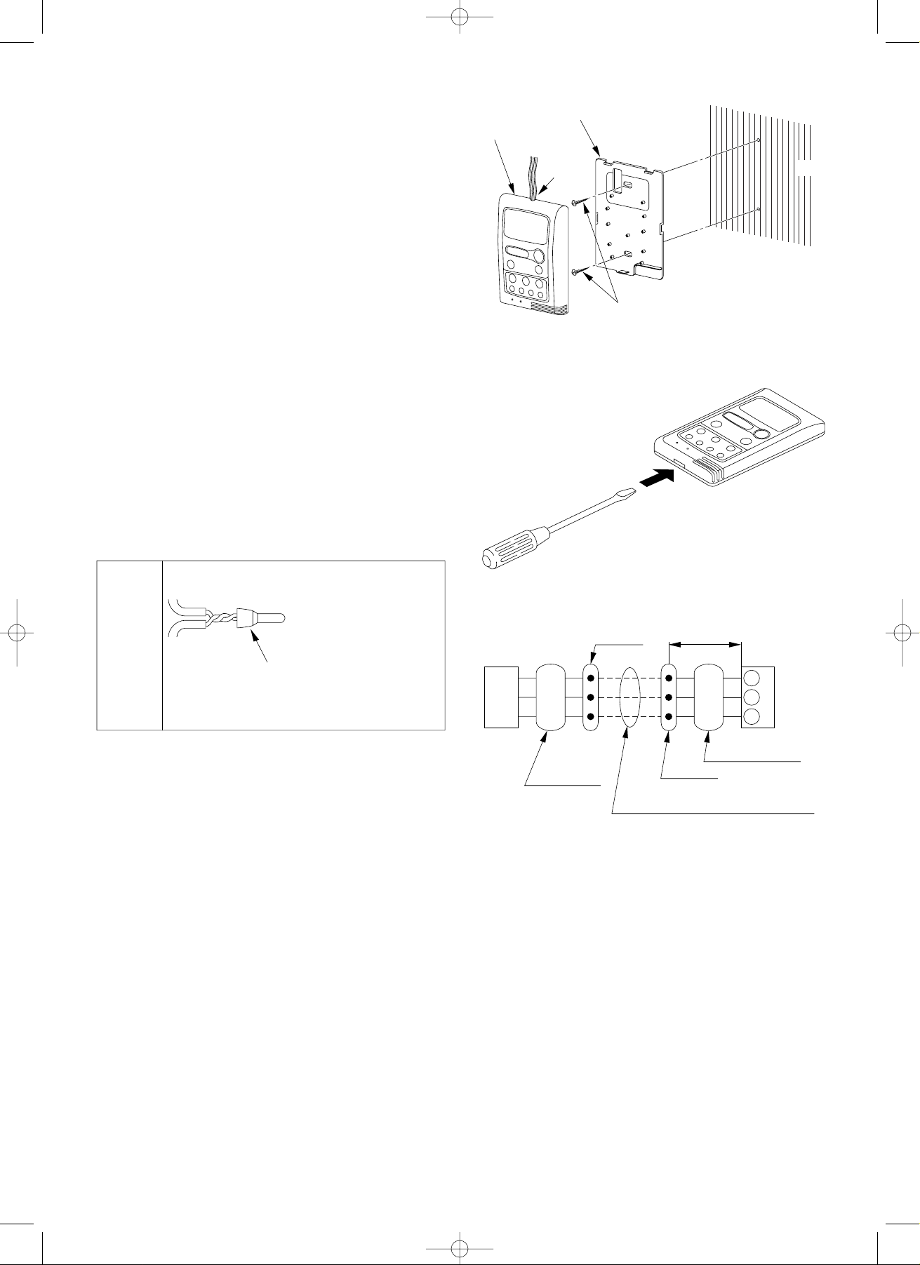
• For surface mounting on the wall, see Fig. 2.
1. Insert a screwdriver or the like in the groove on the
lower side of the remote controller to pry off the
back case. (See Fig. 3)
2. Use the 2 supplied M4 × 25 machine screws for
embeded mounting or M4 × 25 tapping screws for
surface mounting to secure the remote controller
back case. Prior to mounting, clear the cutouts in
the back case corresponding to the holes in the
wall box using a screwdriver or the like. Use the
spacers and take care not to tighten the screws
excessively. If the back case will not seat properly,
cut the spacers to a suitable thickness.
3. Connect locally supplied 3-core lead wires to the
lead wires from the remote controller. (See “How to
wire the remote controller.”)
(The remote controller will be damaged if
220/240V AC is applied.)
4. Hook the remote controller to the tabs of the back
case and mount it.
■ How to wire the remote controller
●
Connection diagram
See Fig. 4.
●
How to connect the harness (supplied parts)
1. Turn off the power, and remove the grille.
2. Remove the screws of the electrical box and
remove its cover.
3. Pull out the indoor unit controller (PCB ass’y).
(Fig. 6 on next page)
4. Pull out the lead wire that connects the remote con-
trol receiver to CN11 of the controller (PCB ass’y).
(Fig. 5 on next page)
5. Plug the socket of the supplied wire harness onto
CN11.
6. Bind the wire harness and the inter-unit lead wires
together, and route them. Fasten them under the
electrical box with the clamp. Then, pull them out
from the back of the indoor unit.
If required, connect the lead wire (field supply, max.
10 m). (Fig.4)
Use the supplied wire joints (6 pcs.) to connect the
lead wire. (See the connection diagram as shown at
right.)
Fig. 3
Fig. 4
Fig. 2
03-242.Sanyo.85464359404000 8/21/03 9:17 AM Page 2
Under-case (back case)
Remote controller
Lead
wires (3)
Wall
Tapping screws
M4 × 25 (2)
6 supplied
white wire
joints
Lead wire from
indoor unit
Lead wire
from
remote controller
1. Peel off 14mm of cable
sheathing on each wire.
2. Twist the 2 wires
together and crimp them
together with a wire joint.
3. When a crimping tool is
Wire
joint
not used, solder the
wires together and cover
the joint with insulating
tape.
Indoor
unit
*1: 0.5mm
Wire joint
RED
WHT
BLK
Wiring from
indoor unit
2
to 2.0mm2 wires are used for lead wires.
*1
Wiring for remote
controller (supplied locally), Max. 10m
Approx. 200mm
RED
WHT
BLK
Wiring from
remote controller
Wire joint
1
2
3
Remote
Controller
Page 3

3
Fig. 5
Fig. 6
03-242.Sanyo.85464359404000 8/21/03 9:17 AM Page 3
• Electric Wiring Diagram
FAN MOTOR
FMI
GRN / YEL
G
G
TERMINAL
PLATE
WHT
BLK
G
GRN
RED
1
2
G
4
FROM
OUTDOOR UNIT
BLK
VLT
YEL
ORG
87654321
87654321
CONNECTOR
[WHT]
FLP
PNK
BRN
GRY
WHT
CONNECTOR
[WHT]
CAPACITOR
PNK
BRN
GRY
WHT
VLT
ORG
YEL
BLK
[WHT] [WHT]
1
1
2
2
3
3
4
4
5
5
WHT
BLU
BLU
BLU
BLU
FLAP MOTOR [UPPER]
CONNECTOR
[WHT] [GRN] [BLK]
FLP
*
FLAP MOTOR [LOWER]
WHT
1
1
BLU
2
2
BLU
3
3
BLU
4
4
BLU
5
5
(RC1)
1
1
2
2
3
3
4
4
5
5
1
1
2
2
3
3
4
4
5
5
GRN
w
G
FM
w
w
HH
w
H
w
M
w
L
w
LL
FLAP1
5P [WHT]
CONTROLLER
FLAP2
5P [BLK]
135
135
SUP
5P [WHT]
PRY
3P [RED]
SEC
2P [WHT]
RECEIVER
3P [WHT]
LAMP
4P [WHT]
ROOM/COIL
4P [WHT]
WHT
1
1
WHT
3
3
121
3
2
1
1
2
3
4
BRN
BRN
2
3
WHT CN11
2
GRY
1
GRY
WHT
1
GRY
2
GRY
3
GRY
4
P
S
1
1
2
2
3
3
4
4
5
5
6
6
7
7
COIL THERMISTOR (TH1)
BLK
1
1
BLK
2
2
BLK
3
3
BLK
4
4
ROOM THERMISTOR (TH2)
8512-5253-714XX-1 (KS2432A)
POWER
TRANSFORMER (TR1)
IND LAMP ASSY
Indoor Electrical Component Box
TRANS
C
BP
1 2G4
Upper flap motor
*GREEN MARK on
lower flap motor
Lower flap motor*
Controller (PCB ass'y
Power transformer (TR1)
Fan motor capacitor (RC1)
Terminal plate
Room thermistor (TH2)
Coil thermistor (TH1)
Clamp lead wires.
Indicator lamp ass'y
)
Grille air outlet
(
Side View
)
Page 4

4
Fig. 7
■ How to test run the air conditioner
1. Switch on the power source.
2. Press the ON/OFF button on the remote control unit
once.
3. Set the operation selector switch of the indoor unit
to the TEST position. This starts the fan, producing
uncooled forced air. (Fig. 7)
4. After 3 minutes, the system shifts into cooling operation, and cool air will start to be felt. Cooling operation with the switch at the TEST position is unaffected by the room temperature.
5. After stopping the test run, turn the operation selector switch of the indoor unit to the OFF position
once, then move to ON position. (Fig. 7)
6. Press the ON/OFF button on the remote control unit
to stop the air conditioner.
If the unit does not operate and the OPERATION lamp
on the unit is blinking after going through the procedure, check the wiring between the units.
NOTE
03-242.Sanyo.85464359404000 8/21/03 9:17 AM Page 4
INDOOR UNIT
OPERATION lamp
OPERATION
TIMER lamp
TIMER
Remote control
receiver
ON
OFF
TEST
Operation selector
 Loading...