

Page 1
INSTALLATION INSTRUCTIONS
– Split System Air Conditioner –
COOL/DRY Model
In order to protect the environment, this air conditioner uses the new refrigerant R410A.
Contents
Page
IMPORTANT!
Please Read Before Starting.................................. 1
1. GENERAL.......................................................... 2
1-1. Tools Required for Installation (not supplied)
1-2. Accessories Supplied with Indoor Unit
1-3. Optional Copper Tubing Kit
1-4. Type of Copper Tube and Insulation Material
1-5. Field Wiring
1-6. Additional Materials Required for Installation
1-7. Operating Range
2. INSTALLATION SITE SELECTION................... 3
2-1. Indoor Unit
2-2. Outdoor Unit
2-3. Air Discharge Chamber for Top Discharge
2-4. Wind Shield for “CL” Model
3. HOW TO INSTALL THE INDOOR UNIT ........... 6
3-1. Remove the Rear Panel from the Unit
3-2. Make a Hole
3-3. Install the Rear Panel on the Wall
3-4. Remove the Grille to Install the Indoor Unit
3-5. Shape the Indoor Side Tubing
3-6. Wiring Instructions
3-7. Recommended Wire Length and Diameter
3-8. Wiring Instructions for Inter-unit Connections
3-9. Mounting
3-10. Drain Hose
4. REMOTE CONTROL UNIT INSTALLATION
POSITION ........................................................ 14
4-1. Mounting on a Wall
5. ADDRESS SWITCHES..................................... 15
6. HOW TO INSTALL THE OUTDOOR UNIT....... 16
6-1. Removing the Packaging Skid
6-2. Installing the Outdoor Unit
6-3. Tubing Direction
Combine indoor and outdoor units only as listed
below.
Indoor Unit Outdoor Units
KS2462R C2462R
Power supply: 60Hz, single-phase, 208/230V
Units should be installed by a licensed contractor
according to local code requirements.
7. ELECTRICAL WIRING ..................................... 17
7-1. General Precautions on Wiring
7-2. Recommended Wire Length and Wire
Diameter for Power Supply System
7-3. Wiring System Diagram
7-4. Examples of Incorrect Wiring
8. HOW TO PROCESS TUBING.......................... 19
8-1. Use of the Flaring Method
8-2. Flaring Procedure with a Flare Tool
8-3. Caution before Connecting Tubes Tightly
8-4. Precautions During Brazing
8-5. Indoor Unit Tubing
8-6. Connecting Tubing between Indoor and
Outdoor Units
8-7. Insulation of Refrigerant Tubing
8-8. Taping the Tubes
8-9. Finishing the Installation
9. AIR PURGING................................................... 22
10. TEST RUN......................................................... 25
10-1. Preparing for Test Run
10-2. Performing Test Run
11. REFRIGERANT R410A: SPECIAL PRECAUTIONS
WHEN INSTALLING UNIT ................................ 28
11-1. Characteristics of New Refrigerant R410A
11-2. Checklist Before Installation
11-3. Tools Specifically for R410A
1 1-4. Charging Additional Refrigerant
Model Combinations
CL2462R
In Canada
SANYO FISHER COMPANY SANYO Canada Inc.
A DIVISION OF SANYO NORTH AMERICA CORPORATION 300 Applewood Crescent
21605 Plummer Street Concord, Ontario
85464359328000 © SANYO 2002 Chatsworth, CA 91311 U.S.A. L4K 5C7, Canada
Page 2
IMPORTANT!
WARNING
WARNING
CAUTION
CAUTION
Please Read Before Starting
This air conditioning system meets strict safety and operating standards. As the installer or service person, it is an
important part of your job to install or service the system so
it operates safely and efficiently.
For safe installation and trouble-free operation, you must:
●
Carefully read this instruction booklet before beginning.
●
Follow each installation or repair step exactly as
shown.
●
Observe all local, state, and national electrical codes.
●
Pay close attention to all warning and caution notices
given in this manual.
This symbol refers to a hazard or
unsafe practice which can result
in severe personal injury or
death.
This symbol refers to a hazard
or unsafe practice which can
result in personal injury or product or property damage.
If Necessary, Get Help
When Installing…
…In a Ceiling, Wall or Floor
Make sure the ceiling/wall/floor is strong enough to hold
the unit’s weight. It may be necessary to construct a
strong wood or metal frame to provide added support.
…In a Room
Properly insulate any tubing run inside a room to prevent
“sweating” that can cause dripping and water damage to
walls and floors.
…In Moist or Uneven Locations
Use a raised concrete pad or concrete blocks to provide a
solid, level foundation for the outdoor unit. This prevents
water damage and abnormal vibration.
…In an Area with High Winds
Securely anchor the outdoor unit down with bolts and a
metal frame. Provide a suitable air baffle.
…In a Snowy Area (for Heat Pump-type Systems)
Install the outdoor unit on a raised platform that is higher
than drifting snow. Provide snow vents.
When Connecting Refrigerant Tubing
These instructions are all you need for most installation
sites and maintenance conditions. If you require help for a
special problem, contact our sales/service outlet or your
certified dealer for additional instructions.
In Case of Improper Installation
The manufacturer shall in no way be responsible for
improper installation or maintenance service, including
failure to follow the instructions in this document.
SPECIAL PRECAUTIONS
When Wiring
ELECTRICAL SHOCK CAN CAUSE SEVERE PERSONAL INJURY OR DEATH. ONLY A QUALIFIED,
EXPERIENCED ELECTRICIAN SHOULD ATTEMPT
TO WIRE THIS SYSTEM.
• Do not supply power to the unit until all wiring and tubing are completed or reconnected and checked.
• Highly dangerous electrical voltages are used in this
system. Carefully refer to the wiring diagram and these
instructions when wiring. Improper connections and
inadequate grounding can cause accidental injury or
death.
• Ground the unit following local electrical codes.
• Connect all wiring tightly. Loose wiring may cause overheating at connection points and a possible fire hazard.
When Transporting
Be careful when picking up and moving the indoor and outdoor units. Get a partner to help, and bend your knees when
lifting to reduce strain on your back. Sharp edges or thin aluminum fins on the air conditioner can cut your fingers.
• Use the flare method for connecting tubing.
• Apply refrigerant lubricant to the matching surfaces of
the flare and union tubes before connecting them, then
tighten the nut with a torque wrench for a leak-free connection.
• Check carefully for leaks before starting the test run.
When Servicing
• Turn the power OFF at the main power box (mains)
before opening the unit to check or repair electrical
parts and wiring.
• Keep your fingers and clothing away from any moving
parts.
• Clean up the site after you finish, remembering to check
that no metal scraps or bits of wiring have been left
inside the unit being serviced.
Others
• Ventilate any enclosed areas when installing or testing
the refrigeration system. Escaped refrigerant gas, on
contact with fire or heat, can produce dangerously toxic
gas.
• Confirm upon completing installation that no refrigerant
gas is leaking. If escaped gas comes in contact with a
stove, gas water heater, electric room heater or other
heat source, it can produce dangerously toxic gas.
1
Page 3
1. General
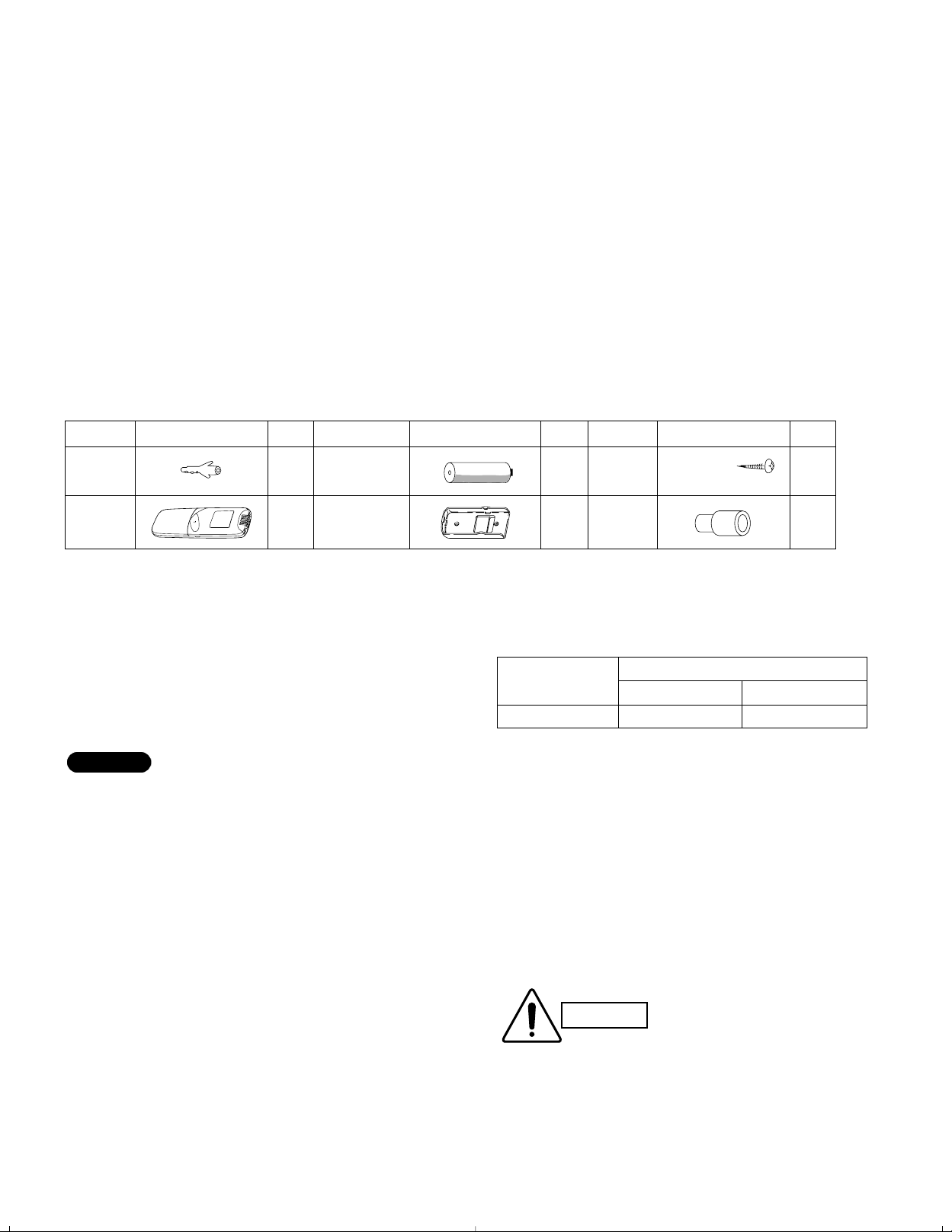
Parts Figure Q’ty Parts Figure Q’ty
12
1
1
Remote
control unit
Parts Figure Q’ty
12
Tapping
screw
Truss-head
Phillips
5/32 × 5/8" (
4 × 16 mm)
2
1
AAA alkaline
battery
Joint drain
Rawl plug
Remote control
holder
NOTE
CAUTION
This booklet briefly outlines where and how to install the
air conditioning system. Please read over the entire set
of instructions for the indoor and outdoor units and make
sure all accessory parts listed are with the system before
beginning.
1-1. Tools Required for Installation (not supplied)
1. Standard screwdriver
2. Phillips head screwdriver
3. Knife or wire stripper
4. Tape measure
5. Carpenter’s level
1-2. Accessories Supplied with Indoor Unit
Table 1
6. Sabre saw or key hole saw
7. Hacksaw
8. Core bits
9. Hammer
10. Drill
11. Tube cutter
12. Tube flaring tool
13. Torque wrench
14. Adjustable wrench
15. Reamer (for deburring)
16. Pipe bending tool (spring bender)
1-3. Optional Copper Tubing Kit
Copper tubing for connecting the outdoor unit to the
indoor unit is available in kits which contain the narrow
and wide tubing, fittings and insulation. Consult your
nearest sales outlet or A/C workshop.
For rear-left tubing, optional tube connec-
tion (C) (APR-EN46U1B) is necessary. See
page 20.
Also consult your nearest sales outlet or A/C workshop.
1-4. Type of Copper Tube and Insulation Material
If you wish to purchase these materials separately from a
local source, you will need:
1. Deoxidized annealed copper tube for refrigerant tub-
ing as detailed in Table 2.
When cutting tubing, add approximately 12 to 16 in.
to each tube length to reduce vibration between the
air conditioning units.
2
Table 2
Model
KS2462R
Narrow Tube
Outer Diameter
3/8"
Wide Tube
3/4"
2. Foamed polyethylene insulation for the specified copper tubes as required to precise length
of tubing. Wall thickness of the insulation
should be not less than 5/16".
1-5. Field Wiring
Use insulated copper wire for field wiring. Wire
size varies with the total length of wiring. Refer to
3-6. Wiring Instructions for details.
Check local electrical codes
and regulations before obtaining wire. Also, check any specified instructions or limitations.
Page 4
1-6. Additional Materials Required for Installation
6 in.
min.
6 in.
min.
6 in. min.
Front View
INDOOR
UNIT
Tubing length (L)
OUTDOOR
UNIT
Elevation
difference (H)
Indoor unit
Floor level
Wall
Minimum height
from floor level
5 ft.
CAUTION
Drain hose
Indoor unit
Outside drainage
1. Refrigeration (armored) tape
2. Insulated staples or clamps for connecting wire
(See local codes)
3. Putty
4. Refrigeration lubricant
5. Clamps or saddles to secure refrigerant tubing
1-7. Operating Range
Temperature Indoor Air Intake Outdoor Air Intake
Cooling
Maximum 95°F DB, 71°F WB 115°F DB
Minimum 67°F DB, 57°F WB 67°F DB, (0°F DB)*
*CL
2. Installation Site Selection
2-1. Indoor Unit
To prevent abnormal heat genera-
WARNING
AVOID:
●
direct sunlight.
●
nearby heat sources that may affect performance of the
unit.
●
areas where leakage of flammable gas may be expected.
●
places where large amounts of oil mist exist.
DO:
●
select an appropriate position from which every corner of
the room can be uniformly cooled. (High on a wall is best.)
●
select a location that will hold the weight of the unit.
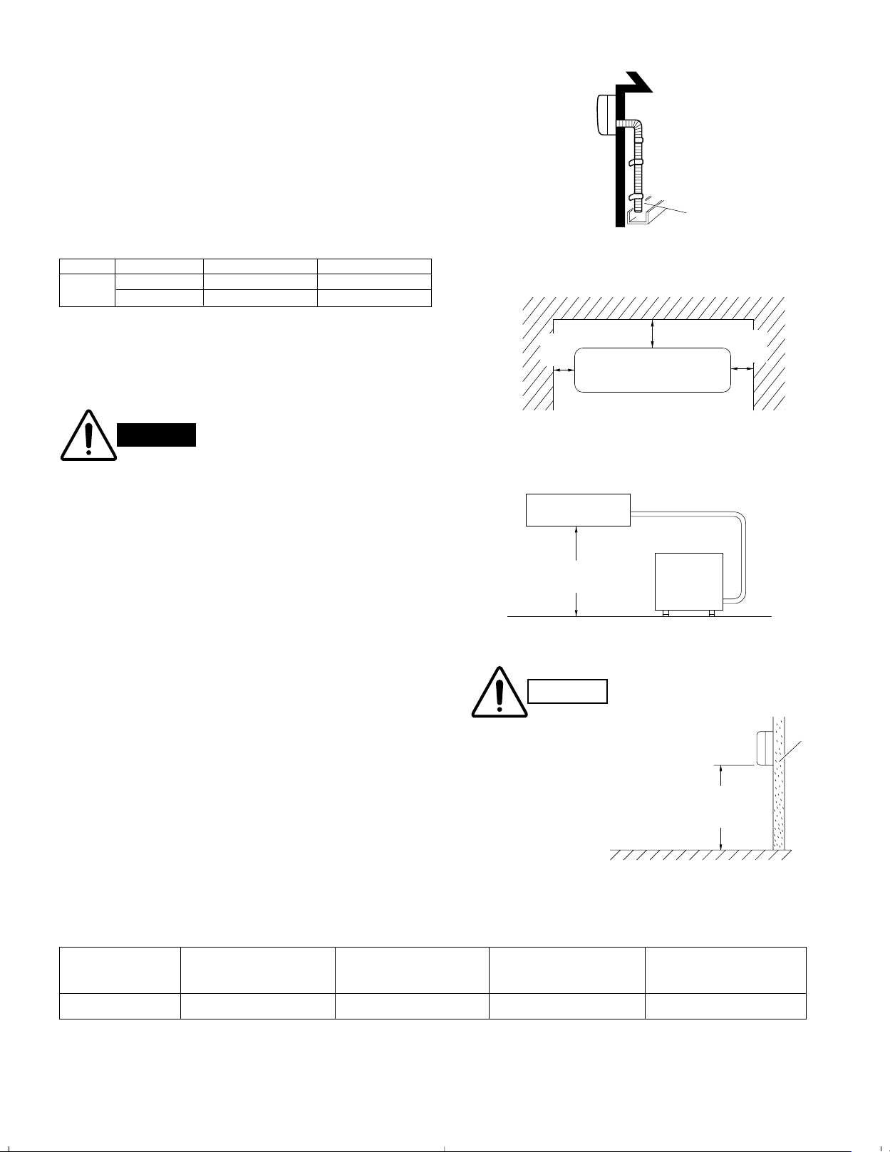
●
select a location where tubing and drain hose have the
shortest run to the outside. (Fig. 1)
●
allow room for operation and maintenance as well as
unrestricted air flow around the unit. (Fig. 2)
●
install the unit within the maximum elevation difference
(H) above or below the outdoor unit and within a total
tubing length (L) from the outdoor unit as detailed in
Table 3 and Fig. 3a.
tion and the possibility of fire, do
not place obstacles, enclosures and
grilles in front of or surrounding the
air conditioner in a way that may
block air flow.
Fig. 1
Models
Fig. 2
Fig. 3a
For stable operation of
the air conditioner, do
not install wall-mounted
type indoor units less
than 5 ft. from floor
level.
Fig. 3b
Table 3
Model Length at Shipment Length (L) Difference (H) Additional Refrigerant
C2462R, CL2462R 23 132 50 0.43
*
If total tubing length becomes 23 to 132 ft. (max.), additional refrigerant (R410A) charge of 0.43 oz./ft. is required.
No additional charge of compressor oil is necessary.
Max. Allowable Tubing Limit of Tubing Limit of Elevation Required Amount of
(ft.) (ft.) (ft.) (oz./ft.)
3
*
Page 5

2-2. Outdoor Unit
Outdoor unit
Hot air
Heat source
Exhaust fan
Min.
1 in.
Min.
1 in.
Min. 2 ft.
Min. 4 inches
Min.
7 ft.
Obstacle above
Ground
Air
discharge
Air in
Air in
Air
discharge
Concrete block
4 in. × 1 ft. 4 in.
beams or equal
Anchor bolts
(4 pieces)
Min. 6 in.
Air discharge
AVOID:
●
heat sources, exhaust fans, etc. (Fig. 4a)
●
damp, humid or uneven locations.
DO:
●
choose a place as cool as possible.
●
choose a place that is well ventilated.
●
allow enough room around the unit for air intake/
exhaust and possible maintenance. (Fig. 4b)
●
provide a solid base a minimum of 6 inches above
ground level to reduce humidity and protect the unit
against possible water damage and decreased service
life. (Fig. 4c)
●
use lug bolts or equal to bolt down unit, to reduce
vibration and noise.
2-3. Air Discharge Chamber for Top Discharge
Fig. 4a
Install the air-discharge chamber in the field when:
●
it is difficult to keep a space of minimum 2 ft. between
the air-discharge outlet and an obstacle.
●
the air-discharge outlet faces a sidewalk and discharged hot air may disturb people passing by.
Refer to Fig. 5a.
Fig. 4b
Fig. 4c
Fig. 5a
4
Page 6
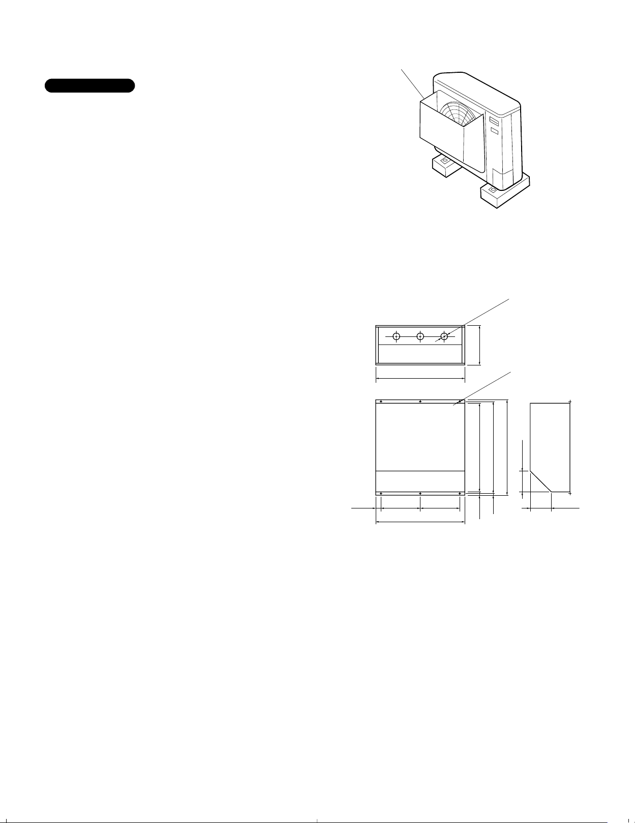
2-4. Wind Shield for “CL” Model
IMPORTANT
Wind shield
(air discharge side)
Front
3 - φ1-9/16" hole
6 - φ15/64" hole
9-27/32"21-5/8"15/16"
5-3/16"
22-7/16"1/2"
23-15/32"
21-13/16"
5-5/32"9-27/32"9-27/32"1-1/16"
21-13/16"
It is recommended to use wind shields for “CL” model
(Fig. 5b). “CL” model is designed to use in low outdoor
temperature conditions.
General
When the outdoor unit is installed in a position exposed
to strong wind (like seasonal winds with low air temperature in winter), a suitable wind shield must be installed
on the outdoor unit.
This unit is designed so that the fan of the outdoor unit
runs at low speed when the air conditioner is operated at
low outdoor air temperatures. When the outdoor unit is
exposed to strong wind, the system pressure drops
because of the freeze protector.
For outer dimensions of the wind shield, see Fig. 5c.
Fig. 5b
Recommended outer dimensions of wind shield
(field supply)
CL2462R
Fig. 5c
5
Page 7
Indoor
side
Outdoor
side
Set screws for transportation only
Right-rear
tubing
(recommended)
Right tubing
Left-rear tubling
Center of
left-rear
tubing hole
Center of
right-rear
tubing hole
NOTE
3. How to Install the Indoor Unit
NOTE
CAUTION
PVC pipe (locally purchased)
Cut at slight angle
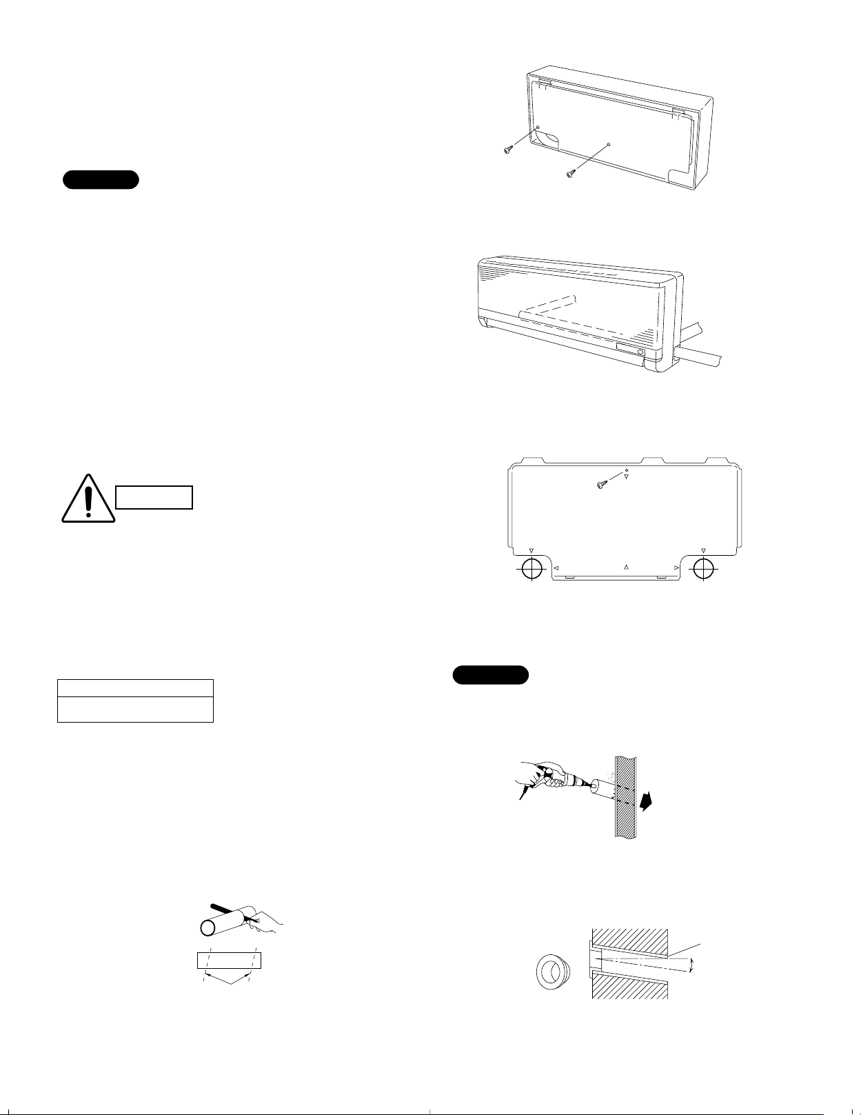
3-1. Remove the Rear Panel from the Unit
Remove and discard the set screws and take off the rear
panel. (Fig. 6)
Tubing can be extended in 3 directions as shown in
Fig. 7a. Select the direction you need providing the
shortest run to the outside unit.
3-2. Make a Hole
(1) Remove the rear panel from the indoor unit and
place it on the wall at the location selected. Make
sure the unit is horizontal, using a carpenter’s level
or tape measure to measure down from the ceiling.
(2) Determine which side of the unit you should make
the hole. (Fig. 7b)
(3) Before making a hole, check carefully that no studs
or pipes are directly run behind the spot to be cut.
Fig. 6
Fig. 7a
In case of left-rear or right-rear tubing
Also avoid areas where electrical wiring or conduits are
located.
The above precautions are also applicable if tubing
goes through the wall in any other location.
(4) Using a sabre saw, key hole saw or hole-cutting drill
attachment, cut a hole in the wall. See Table 4 and
Fig. 8.
Table 4
Hole Dia. (inch)
3-3/16"
(5) Measure the thickness of the wall from the inside
edge to the outside edge and cut PVC pipe at a
slight angle 1/4" shorter than the thickness of the
wall. (Fig. 9)
(6) Place the plastic cover over the end of the pipe (for
indoor side only) and insert in the wall. (Fig. 10)
Fig. 7b
Hole should be made at a slight downward slant to the
outdoor side.
Fig. 8
Fig. 9
INSIDE
Wall
Plastic cover
(Field supply)
OUTSIDE
PVC pipe
Slight
angle
Fig. 10
6
Page 8
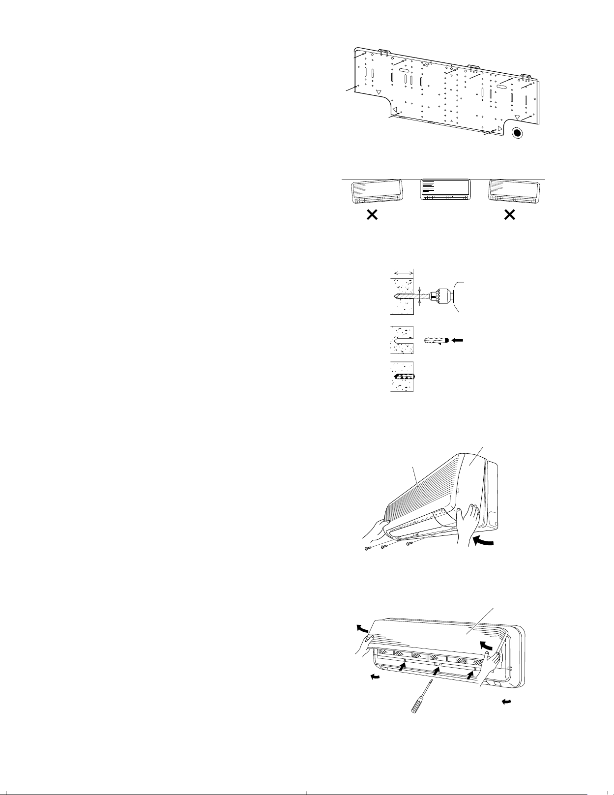
3-3. Install the Rear Panel on the Wall
3/16
"
dia. hole
1-3/16
"
or more
Rawl plug
(Field supply)
Air intake grille
Grille
Air intake grille
Be sure to confirm that the wall is strong enough to suspend the unit.
See either Item a) or b) below depending on the wall
type.
a) If Wooden Wall
(1) Attach the rear panel to the wall with the 10 screws
provided. (Fig. 11)
If you are not able to line up the holes in the rear
panel with the beam locations marked on the wall,
use toggle bolts to go through the holes on the panel
or drill 3/16"dia. holes in the panel over the stud
locations and then mount the rear panel.
(2) Double check with a ruler or carpenter’s level that
the panel is level. This is important to install the unit
properly. (Fig. 12)
(3) Make sure the panel is flush against the wall. Any
space between the wall and unit will cause noise and
vibration.
Fig. 11
Fig. 12
b) If Block, Brick, Concrete or Similar Type Wall
Make 3/16" dia. holes in the wall. Insert rawl plugs for
appropriate mounting screws. (Fig. 13)
3-4. Remove the Grille to Install the Indoor Unit
Basically, these models can be installed and wired without removing the grille. If access to any internal part is
needed, follow the steps as given below:
How to remove the grille
(1) Set the 2 flaps in the horizontal position.
(2) Unscrew the 3 screws. (Fig. 14a)
(3) Remove the grille.
(a) Hold both corners of the air intake grille, then pull
out and up to open. (Fig. 14b)
(b) Use a standard screwdriver to push up the 3 tabs
to remove the grille. (Fig. 14b)
(c) Pull the lower part of the grille toward you to
remove. (Fig. 14a)
Fig. 13
Fig. 14a
Fig. 14b
7
Page 9
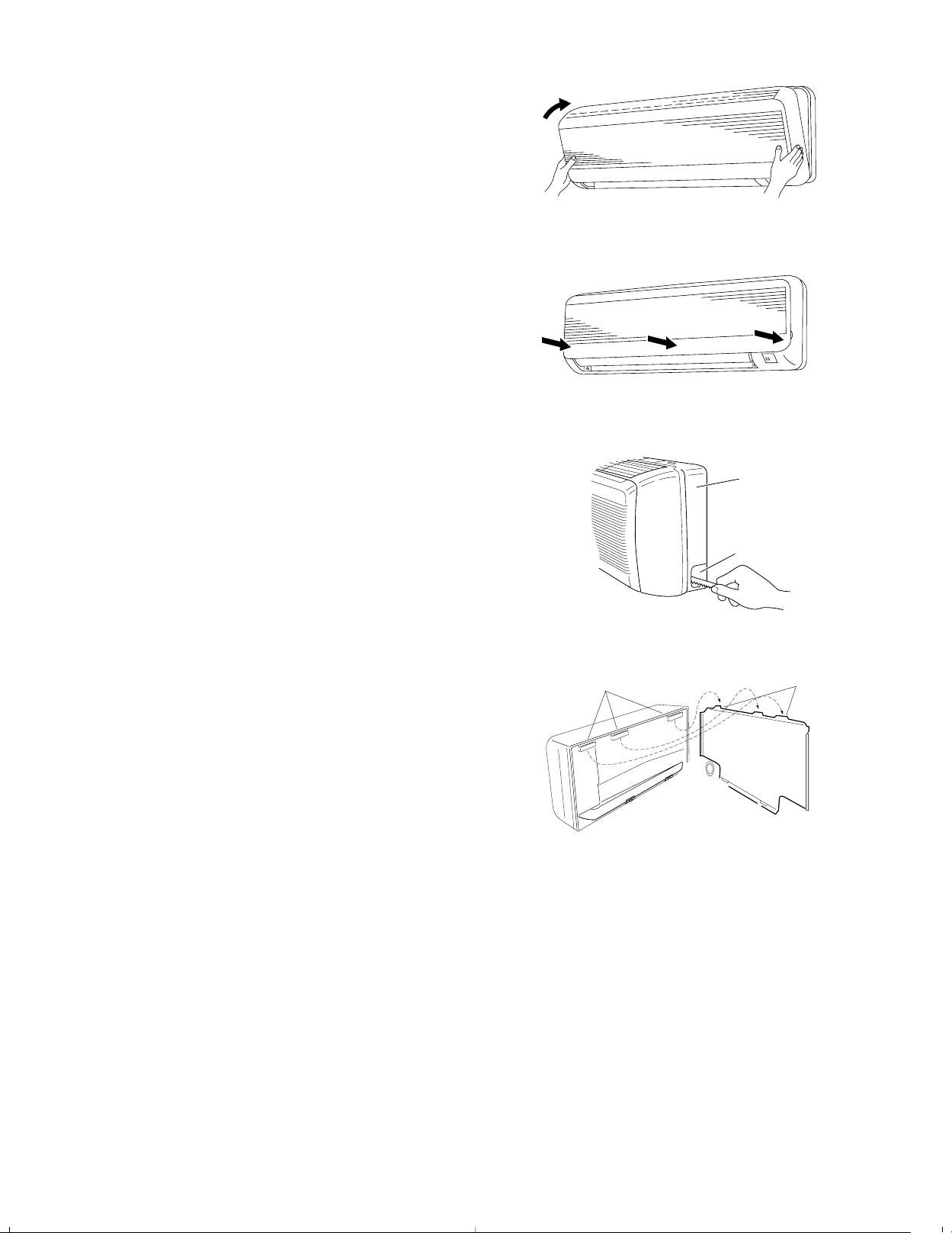
How to replace the grille
Frame
Right tubing
outlet
Tab
Mounting slot
(1) Close the flaps.
(2) Reinstall the grille into the lower part while aligning
its tabs on the upper part. (Fig. 15a) Insert the tabs
in the slots and push the lower part of the grille back
into position.
(3) Press at each of the 5 tabs to completely close the
grille. Make sure that the grille and frame are firmly
fitted together. (Fig. 15b)
3-5. Shape the Indoor Side Tubing
1) Arrangement of tubing by directions
a) Right tubing
Fig. 15a
The corner of the right frame needs to be cut by a
hacksaw or the like. (Fig. 16)
b) Right-rear or left-rear tubing
In this case, the corner of the frame need not be
cut.
2) To mount the indoor unit on the rear panel:
Hang the 3 mounting slots of the unit on the
upper tabs of the rear panel. (Fig. 17)
3-6. Wiring Instructions
General precautions on wiring
1) Before wiring, confirm the rated voltage of the unit as
shown on its nameplate, then carry out the wiring
closely following the wiring diagram.
2) Provide a power outlet to be used exclusively for
each unit, with a power supply disconnect and circuit
breaker for overcurrent protection provided in the
exclusive line.
3) To prevent possible hazard due to insulation failure,
the unit must be grounded.
Fig. 15b
Fig. 16
Fig. 17
4) Each wiring connection must be done tightly and in
accordance with the wiring system diagram. Wrong
wiring may cause the unit to misoperate or become
damaged.
5) Do not allow wiring to touch the refrigerant tubing,
compressor, or any moving parts of the fan.
6) Unauthorized changes in the internal wiring can be
very dangerous. The manufacturer will accept no
responsibility for any damage or misoperation that
occurs as a result of such unauthorized changes.
8
Page 10
3-7. Recommended Wire Length and Diameter
2
4
2
4
11
INDOOR
UNIT
Terminal
OUTDOOR
UNIT
(B)
Terminal
(A)
L2
L1
G
G
G
230V/208V
230V/208V
230V/208V
(Inter-unit)
power line
Grounding line
Grounding
line
Power supply
Single-phase 230V/208V 60HZ
Disconnect
switch
Field supply
WARNING
CAUTION
Regulations on wiring diameter differ from locality to
locality. For field wiring requirements, please refer to
your local electrical codes. Carefully observe these regulations when carrying out the installation.
Table 5 lists recommended wire lengths and diameters
for power supply systems.
Refer to the wiring system diagram (Fig. 18) for the
meaning of “A” and “B” in Table 5.
Table 5
AWG
Model
C2462R,CL2462R 64 (Max.) 132 (Max.) 35A
(A) Power Supply
Wiring Length (ft.)
(#12)
(B) Inter-Unit
Power Line
(#14)
# …AWG (American Wire Gauge)
Fuse or Circuit
Capacity
WARNING
●
Be sure to comply with local
codes on running the wire
from the indoor unit to the
outdoor unit (size of wire and
wiring method, etc.).
●
Each wire must be firmly
connected.
●
No wire should be allowed to
touch refrigerant tubing, the
compressor, or any moving
part.
To avoid the risk of electric
shock, each air conditioner
unit must be grounded.
Be sure to connect the power
supply line to the outdoor unit
as shown in the wiring diagram. The indoor unit draws its
power from the outdoor unit.
WIRING SYSTEM DIAGRAM
Fig. 18
9
Page 11

3-8. Wiring Instructions for Inter-unit Connections
Rear
panel
Wiring
Wall
10 in.
Plastic
cover
Terminal
plate
Cover plate
Lock nut
Top of conduit
connector
Inter-unit
control line
wiring
Earth
plate
(1) Insert the inter-unit wiring (according to local codes)
into the through-the-wall PVC pipe. Run the wiring
toward the indoor side allowing approx. 10 inches to
extend from the wall face. (Fig. 19)
(2) Route the inter-unit wiring from the back of the
indoor unit and pull it toward the front for connection.
(Figs. 20a and 20b)
(3) Connect the inter-unit wiring to the corresponding
terminals on the terminal plate (Figs. 20a and 20b)
while referring to the wiring diagram.
(4) Be sure to secure the wiring with the provided
clamp.
How to remove the cover plate
To access the terminal plate inside the indoor unit, follow
these steps.
(1) Using a Phillips screwdriver, remove the screw on
the cover plate. (Figs. 20a and 20b)
(2) Remove the cover plate.
Fig. 19
Fig. 20a
Fig. 20b
10
Page 12

NOTE
Solid wire
Loop
Insulation
Strip 1 inch
Stranded wire
Ring
connector
Strip 3/8 inch
Screw with
special washer
Ring connector
Terminal plate
Wire
Screw with
special washer
Ring
connector
Wire
WARNING
Loose wiring may cause the
Twist wire ends
terminal to overheat or result
in unit malfunction. A fire hazard may also exist. Therefore,
be sure all wiring is tightly
connected.
When connecting each power wire to the corresponding
terminal, follow the instructions “How to connect wiring to
the terminal” and fasten the wire securely tight with the
fixing screw of the terminal plate.
How to connect wiring to the terminal
■
For solid core wiring (or F-cable)
Fig. 21a
(1) Cut the wire end with a cutting pliers, then strip the
insulation to expose the solid wire about 1 in.
(Fig. 21a)
(2) Using a screwdriver, remove the terminal screw(s)
on the terminal plate.
(3) Using the pliers, bend the solid wire to form a loop
suitable for the terminal screw.
(4) Shape the loop wire properly, place it on the termi-
nal plate and fix it securely with the removed terminal screw using a screwdriver.
■
For stranded wiring
(1) Cut the wire end with a cutting pliers, then strip
the insulation to expose the stranded wiring about
3/8 in. and tightly twist the wire ends.
(Figs. 21b and 21c)
(2) Using a screwdriver, remove the terminal screw(s)
on the terminal plate.
(3) Using a ring connector fastener or pliers, securely
clamp each stripped wire end with a ring connector.
(Fig. 21b)
(4) Place the ring connector wire, and replace and tight-
en the removed terminal screw using a screwdriver.
(Fig. 22)
Fig. 21b
Fig. 21c
Fig. 22
Being careful not to cut the wire, strip off the plastic insulation using a wire cutter or pliers. (Fig. 23)
Fig. 23
11
Page 13

3-9. Mounting
Cover
Refrigerant
tubing
Drain hose
Inter-unit
wiring
Pipe bending tool
a
b
b / a = 0.7 or more
Insulation
(Field supply)
Refrigerant tubing
Drain hose
Conduit
Inter-unit wiring
CAUTION
CAUTION
■
Right-side tubing
(1) Shape the refrigerant tubing so that it can easily go
into the wall hole. (Fig. 24)
If using a stepladder, be careful
to keep your balance and not
fall off. To prevent the unit
from damage and avoid personal injury, ask for someone’s
help when feeding the tubing
through the hole because the
unit is heavy and difficult to
hold in place.
(2) Push the wiring, refrigerant tubing, and drain hose
through the hole in the wall. Adjust the indoor unit so
it is securely seated on the rear panel.
(3) Carefully bend the tubing (if necessary) to run along
the wall in the direction of the outdoor unit and then
tape as far as the fittings.
Fig. 24
Fig. 25
The air conditioner’s performance will be deteriorated if a
tube is crushed. To prevent
crushing of tubing, avoid sharp
bends. Use a pipe bending tool
to bend tubes. (Fig. 25)
(4) Connect the refrigerant tubing to the outdoor unit.
(After performing a leak test on the connecting part,
insulate it with tubing insulation. (Fig. 26)) Also, refer
to Section 4-3. Connecting Tubing between Indoor
and Outdoor Units.
(5) Assemble the refrigerant tubing, drain hose, and
inter-unit wiring as shown in Fig. 27.
Fig. 26
Fig. 27
12
Page 14

3-10. Drain Hose
Slant
Drain
hose
Indoor
unit
Condensation
Insulation material
(locally purchased)
must be used.
a) The drain hose should be slanted downward to the
outdoors. (Fig. 28)
b) Never form a trap in the course of the hose.
c) If the drain hose will run in the room, insulate the
hose with insulation*so that chilled condensation
will not damage furniture or floors. (Fig. 29)
*
Foamed polyethylene or its equivalent is recommended.
Fig. 28
WARNING
Do not supply power to the
unit or operate it until all tubing and wiring to the outside
unit are completed.
Risk of Electric Shock
Fig. 29
13
Page 15

4. Remote Control Unit Installation Position
Truss-head
tapping screw
5/32 × 5/8" (4 × 16 mm supplied)
Remote
control
unit holder
Holder
Holder
Truss-head
tapping screw
5/32 × 5/8" (4 × 16 mm supplied)
The remote control unit can be operated from either a
non-fixed position or a wall-mounted position.
To ensure that the air conditioner operates correctly, do
not install the remote control unit in the following places:
●
In direct sunlight
●
Behind a curtain or other place where it is covered
●
More than 26 ft. (8 m) away from the air conditioner
●
In the path of the air conditioner’s airstream
●
Where it may become extremely hot or cold
●
Where it may be subject to electrical or magnetic
interference
4-1. Mounting on a Wall
1) Confirm the indoor unit beeps when the ON/OFF
button is pressed at the wall location where the
remote control unit is to be attached, then attach
the holder to the wall. (Fig. 30)
2) When taking out the remote control unit, grasp
and pull it from the holder.
When using the remote control unit
• Point the transmission portion of the remote control unit at the receiver area of the indoor unit to
control the air conditioner.
• Do not place objects that may block the transmitted signals between the receiver and the remote
control unit.
When mounting the remote control unit to
prevent theft or loss
1) Mount the holder to the wall with one of the
screws (using only the hole in the top of the
holder) (Fig. 31).
2) Remove the cover of the remote control unit and
take out the batteries. Next, place the remote
control unit in the holder.
3) Fasten both the remote control unit and holder to
the wall with the remaining screw (using the hole
in the bottom of the holder).
4) Install the batteries in the remote control unit and
close the cover.
Fig. 30
Fig. 31
14
Page 16

5. Address Switches
JP11
●
Change the address switch to prevent mixing of signals from remote control units when 2 Sanyo air conditioners are installed next to each other. Normally,
the address switch is set to A. To change the address
to B, break tab Aof the remote control address switch
and cut the jumper cable (JP11) on the indoor unit
board. (Figs. 32 and 33)
If you need more information, contact your air conditioning system dealer.
●
Normally, the tabs on the remote control unit should
not be broken.
Address switch
(tab A)
NOTE
The illustration above pictures the remote control
unit after the cover has been lowered and removed.
Fig. 32
Fig. 33
15
Page 17

6. How to Install the Outdoor Unit
Access panel
Front
Tubing
outlets
Down
Right
Rear
Inter-unit
wiring outlets
Power
supply
wiring
outlets
Power
supply line
Inter-unit
power line
Power supply line Inter unit power line
1/2"
1/2"
6-1. Removing the Packing Skid
Remove the packing skid from the bottom. (Fig. 34)
Place the unit on a level concrete pad, block or equal
and anchor.
Compressor
Refer to Section 2. “Installation Site Selection.”
6-2. Installing the Outdoor Unit
(1) Install blocks or a solid platform under the outdoor
unit which provides a minimum height of 6 in. from
ground level. (Fig. 35)
(2) The outdoor unit must be bolted down tightly to the
blocks or platform with 4 anchor bolts.
6-3. Tubing Direction
●
Tubing can be extended in 4 different directions as
shown in Fig. 36.
●
Service valves are housed inside the unit. To access
them, remove the access panel by removing the 3
attaching screws, then slide the panel downward and
pull it toward you.
If either rear, right or front tubing is needed, punch
out the knockout holes with a hammer and punch or
similar tool.
Packing
skid
Fig. 34
13-3/8
6-11/16 26 4-21/64
Anchor
bolts
(not supplied)
1-3/16 1-3/16
15-3/4
14-31/32
●
●
After punching out the knockout holes, mount plastic
protectors on the tubing outlets. There accessories
are packed inside the unit and can be accessed
through the access panel.
Use tube benders to extend refrigerant tubing to the
outside.
Fig. 36
Height :
Min: 6 in.
Unit: inch
Fig. 35
16
Page 18

7. Electrical Wiring
NOTE
7-1. General Precautions on Wiring
(1) Before wiring, confirm the rated voltage of the unit
as shown on its nameplate, then carry out the wiring
closely following the wiring diagram.
(2) Provide a power outlet to be used exclusively for
each unit, and a power supply disconnect and circuit
breaker for overcurrent protection should be provided in the exclusive line.
(3) To prevent possible hazards from insulation failure,
the unit must be grounded.
(4) Each wiring connection must be done in accordance
with the wiring system diagram. Wrong wiring may
cause the unit to misoperate or become damaged.
(5) Do not allow wiring to touch the refrigerant tubing,
compressor, or any moving parts of the fan.
(6) Unauthorized changes in the internal wiring can be
very dangerous. The manufacturer will accept no
responsibility for any damage or misoperation that
occurs as a result of such unauthorized changes.
(7) Regulations on wire diameters differ from locality to
locality. For field wiring rules, please refer to your
LOCAL ELECTRICAL CODES before beginning.
You must ensure that installation complies with all
relevant rules and regulations.
(8) To prevent malfunction of the air conditioner caused
by electrical noise, care must be taken when wiring
as follows:
●
The inter-unit control wiring and the remote control wiring (option) should be wired apart from the
inter-unit power wiring.
●
It is recommended that shielded wires or twistedpair wires be used for the remote control and the
inter-unit control wiring if the air conditioner is
installed where it is exposed to the influence of
electrical and/or electro-magnetic noise.
7-2. Recommended Wire Length and Wire Diameter for Power Supply System
(B)
*1
Inter-unit
Wiring
Models
*1
Power Supply
(A)
AGW #14
C2462R, CL2462R 64 ft. (AWG #12) 35 A
132 ft.
Time Delay
Fuse or
Circuit
Capacity
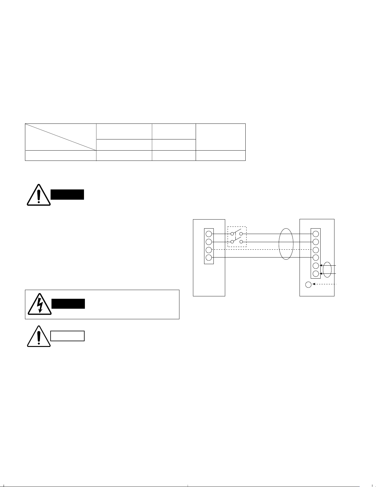
*1 Refer to the Wiring System Diagrams (See below diagram) for the meaning of “A” and “B.”
AWG = American Wire Gauge
Disconnect SW
(Field supply)
To access the electrical component box, open the air
intake grille and remove the electrical component box
cover.
7-3. Wiring System Diagram
Outdoor Unit: “C”, “CL” models
Single-phase
Indoor Unit Outdoor Unit
(B)
1
2
G
Ground
4
60 Hz, 208/230 V
L1
1
2
G
4
(A)
17
L2
G
Ground
Page 19

CAUTION
7-4. Examples of Incorrect Wiring
Problem 1
● Short circuit will occur after approx. 3 minutes.
Problem 2
● Air conditioner will not operate.
Problem 3
● Compressor will not start; only indoor unit will
operate.
1
4
2
G G
Indoor unit Outdoor unit
1
4
2
G G
1
4
2
Indoor unit Outdoor unit
1
4
2
G G
1
4
2
Indoor unit Outdoor unit
1
2
4
G G
1
4
2
Indoor unit Outdoor unit
1
2
4
G G
1
4
2
Indoor unit Outdoor unit
1
2
4
The following are examples of improper wiring that result
in system misoperation. You should confirm that you
have wired the units correctly before beginning the Test
Run described on page 25.
18
Page 20

Deburring
Before
After
Reamer
Copper
tubing
Flare tool
Flare nut
Copper
tubing
Apply refrigerant
lubricant here and here
8. How to Process Tubing
NOTE
NOTE
0 to
0.5 mm
(See 11. REFRIGERANT R410A: SPECIAL PRECAUTIONS)
The narrow tubing side is connected by a flare nut, and
the wide tubing side is connected by brazing.
8-1. Use of the Flaring Method
Many of conventional split system air conditioners employ the
flaring method to connect refrigerant tubes which run
between indoor and outdoor units. In this method, the copper
tubes are flared at each end and connected with flare nuts.
8-2. Flaring Procedure with a Flare Tool
(1) Cut the copper tube to the required length with a tube
cutter. It is recommended to cut approx. 12 to 16 in.
longer than the tubing length you estimate.
(2) Remove burrs at the end of the copper tube with a tube
reamer or file. This process is important and should be
done carefully to make a good flare. (Fig. 37)
When reaming, hold the tube end downward and be sure
that no copper scraps fall into the tube. (Fig. 38a)
Fig. 37
(3) Remove the flare nut from the unit and be sure to
mount it on the copper tube.
(4) Make a flare at the end of copper tube with a flare
tool.*(Fig. 38b)
(*Use “RIGID
®
” or equivalent.)
(5) Use the special flare tool for R410A for making a flare.
If the conventional flare tool (for R22) is used, the
flared portion of the tubing should protrude 1.0 to
1.5 mm. (Fig. 38c)
A good flare should have the following characteristics:
●
inside surface is glossy and smooth.
●
edge is smooth.
●
tapered sides are of uniform length.
8-3. Caution before Connecting Tubes Tightly
(1) Apply a sealing cap or water-proof tape to prevent dust
or water from entering the tubes before they are used.
(2) Apply refrigerant lubricant to the matching surfaces
of the flare and union before connecting them
together. This helps to reduce gas leaks. (Fig. 39a)
When R410A
flare tool is used
Fig. 38a
Fig. 38b
When conventional flare tool is
used (clutching method)
1.0 1.5 mm
Flare the tubing by 1.0 to 1.5 mm.
Fig. 38c
Fig. 39a
19
Page 21

(3) For proper connection, align the union tube and flare tube
B'
B
A'
2. Mount the rear panel
A
Rear View
Wide tube
Optional tube
connection (C) 1/2"
(Optional part)
1. Cut hole
in wall
3. Cut
4. Flare
5. Connect
4-1/8"
4. Flare wide tube
3. Cut wide tube
5. Connect tube
assy
Optional tube
connection (C) 1/2"
(Optional part)
Narrow
tube 3/8"
6. Connect
wide tube
3/4"
7. Connect
narrow tube
3/8"
NOTE
Flare nut
Union
with each other, then screw in the flare nut lightly at first to
obtain a smooth match. (Fig. 39b)
●
Adjust the shape of the narrow and wide tubes using a tube
bender at the installation site and connect them to the each
tubing side valve using a flare nut.
8-4. Precautions During Brazing
●
Replace air inside the tube with nitrogen gas to prevent copper oxide film from forming during the brazing process.
●
Do not allow the tubing to get too hot during the brazing
process. The nitrogen gas inside the tubing may
overheat, causing refrigerant system valves to
become damaged. Therefore allow the tubing to cool
between brazings.
8-5. Indoor Unit Tubing
■
Rear-left tubing
For rear-left tubing, optional tube connection (C) (APREN46U1B) is necessary. Please consult your nearest
sales outlet or A/C workshop.
Fig. 39b
1. Make a 3-3/16" hole in the wall, centered on the
crossing point between the triangle marks (A and B)
on the rear panel. (Fig. 40a)
2. Set the rear panel at its original position where it was
installed with screws.
3. Cut the wide tube at a point 4-1/8" from the triangle mark.
4. Remove the 1/2" flare nut from the optional tube connection (C), place it on the cut wide tube, and then flare the
wide tube. (Fig. 40b)
5. Connect the optional tube connection (C) to the wide tube.
6. Connect the 3/4" tube to the connected optional tube connection.
7. Connect the 3/8" tube to the narrow tube.
8. Cover the narrow and wide tubes with insulation material.
■
Rear-right tubing
9. Make a 3-3/16" hole in the wall, centered on the crossing
point between the triangle marks (A' and B') on the rear
panel. (Fig. 40a)
10. Connect the 3/4" tube to the wide tube.
11. Connect the 3/8" tube to the narrow tube.
12. Cover the narrow and wide tubes with insulation material.
Fig. 40a
Fig. 40b
20
Page 22

Apply putty here
Tubing
Clamp
Insulated tubes
Insulation
Min.
5/16"
Thickness:
min. 5/16"
8-6. Connecting Tubing between Indoor and
NOTE
IMPORTANT
Indoor unit
Outdoor unit
Spanner
Torque wrench
Insulation
(Field supply)
Outdoor Units
a) Tightly connect the indoor side refrigerant tubing
extended from the wall with the outdoor side tubing.
(Fig. 41)
b) To fasten the flare nuts, apply specified torque as:
Table 6
Tube Dia. Tightening Torque
3/8" Approx. 300 – 340 lbs..in (35 – 40 N.m)
3/4" Approx. 870 – 1,040 lbs..in (100 – 120 N.m)
8-7. Insulation of Refrigerant Tubing
(For C2462R and CL2462R)
Fig. 41
To prevent heat loss and wet floors due to dripping of
condensation, both tubes must be well insulated with
a proper insulation material. The thickness of the insulation should be a minimum 5/16" (Fig. 43)
8-8. Taping the Tubes
CAUTION
After a tube has been insulated,
never try to bend it into a narrow curve, as this may cause
the tube to break or crack.
(1) At this time, the 2 refrigerant tubes (and electrical wire
if local codes permit) should be taped together with
armoring tape. The drain hose may also be included
and taped together as 1 bundle with the tubing.
(2) Wrap the armoring tape from the bottom of the out-
door unit to the top of the tubing where it enters the
wall. As you wrap the tubing, overlap half of each
previous tape turn. (Fig. 44)
(3) Clamp the tubing bundle to the wall, using 1 clamp
approx. every 4 ft.
Fig. 42
Fig. 43
Fig. 44
Do not wind the armoring tape too tightly since this will
decrease the heat insulation effect. Also be sure the
condensation drain hose splits away from the bundle
and drips clear of the unit and the tubing.
8-9. Finishing the Installation
After finishing insulating and taping over the tubing, use
sealing putty to seal off the hole in the wall to prevent
rain and draft from entering. Fig. 45 shows refrigerant
tubing taped separately from the drain hose.
Fig. 45
21
Page 23

9. Air Purging
CAUTION
Manifold valve
Air and moisture remaining in the refrigerant system
have undesirable effects as indicated below. Therefore,
they must be purged completely.
●
pressure in the system rises
●
operating current rises
●
cooling (or heating) efficiency drops
●
moisture in the air may freeze and block capillary tubing
●
water may lead to corrosion of parts in the refrigerant
system
■
Air Purging with a Vacuum Pump (for Test Run)
Check that each tube (both narrow and wide tubes)
between the indoor and outdoor units have been properly connected and all wiring for the test run has been
completed. Remove the valve caps from both the wide
and narrow service valves on the outdoor unit. Note that
both narrow and wide tube service valves on the outdoor
unit are kept closed at this stage.
Leak test
(1) With the service valves on the outdoor unit closed,
remove the 1/4". flare nut and its bonnet on the wide
tube service valve. (Save them for reuse.)
Pressure
gauge
Lo Hi
Charge hose
Nitrogen gas cylinder
(In vertical standing
position)
Outdoor unit
Service
valve
Wide tubeNarrow
tube
(2) Attach a manifold valve (with pressure gauges) and
dry nitrogen gas cylinder to this service port with
charge hoses.
Use a manifold valve for air
purging. If it is not available,
use a stop valve for this purpose. The “Hi” knob of the
manifold valve must always be
kept closed.
(3) Pressurize the system to no more than 150 P.S.I.G.
with dry nitrogen gas and close the cylinder valve
when the gauge reading reaches 150 P.S.I.G. Then,
test for leaks with liquid soap.
Pressure
gauge
Indoor unit
Fig. 46
Manifold valve
Lo Hi
Cap
Nitrogen gas
cylinder
Narrow tube
Wide tube
Fig. 47
22
Page 24

Manifold valve
CAUTION
NOTE
To prevent nitrogen from enter
the refrigerant system in the
liquid state, the top of the
cylinder must be higher than
the bottom when you pressurize the system. Usually,
the cylinder is used in a
vertical standing position.
(Refer to the previous page.)
(4) Do a leak test of all joints of the tubing (both
indoor and outdoor) and both wide and narrow
service valves. Bubbles indicate a leak. Wipe off
the soap with a clean cloth after the leak test.
(5) After the system is found to be free of leaks,
relieve the nitrogen pressure by loosening the
charge hose connector at the nitrogen cylinder.
When the system pressure is reduced to normal,
disconnect the hose from the cylinder.
Evacuation
(1) Attach the charge hose end described in the
preceding steps to the vacuum pump to evacuate
the tubing and indoor unit.
Confirm that the “Lo” knob of the manifold valve
is open. Then, run the vacuum pump. The
operation time for evacuation varies with the
tubing length and capacity of the pump. The
following table shows the amount of time for
evacuation:
The required time in the above table is calculated
based on the assumption that the ideal (or target)
vacuum condition is around 10 mmHg abs.
(2) When the desired vacuum is reached, close the
“Lo” knob of the manifold valve and turn off the
vacuum pump.
If tubing length is
less than 50 ft.
45 minutes or more
If tubing length is
longer than 50 ft.
90 minutes or more
Required time for evacuation
when 30 gal/h vacuum pump is used
Vacuum pump
Cap
Narrow tube
Wide tube
Manifold valve
Vacuum
gauge
Lo
Hi
Pressure
gauge
Lo Hi
Vacuum pump
Outdoor unit
Service
valve
Wide tubeNarrow
tube
Indoor unit
Fig. 48
Fig. 49
23
Page 25

Charging additional refrigerant
CAUTION
CAUTION
CAUTION
Use a charging cylinder
designed for use with R410A.
●
Calculate the required amount of additional refrigerant
according to narrow tube length (see P. 3, Table 3).
(Fig. 50)
●
Use a balance (scale) to measure the refrigerant accurately.
When charging R410A, due to the
high pressure be sure to carefully open the charging cylinder
valve a little at a time.
●
After the required vacuum level is reached, charge liquid
refrigerant from the charge opening of the liquid-side
valve. Valves must be closed at this time.
Note: If the additional refrigerant charge amount cannot all
be charged at once, charge the remaining refrigerant
in gas form by using the wide tube service valve with
the system in Cooling mode at the time of test run.
●
When the charging is completed, all valves must be fully
opened.
Outdoor
unit
Hex wrench
Max. allowable
tubing length
at shipment
Narrow tube
Wide tube
Narrow tube
132 ft.
Fig. 50
Wide tube
Fig. 51
Indoor
unit
Required
additional
charge
CLOSE OPEN
Finishing the job
(1) With a hex wrench, turn the narrow tube service valve
stem counter-clockwise to fully open the valve. (Fig. 51)
(2) With a screwdriver, turn the wide tube service valve
stem counter-clockwise to fully open the valve. (Fig. 51)
To avoid gas from leaking when
removing the charge hose, make
sure the stem of the wide tube is
turned all the way out (“BACK
SEA T” position).
(3) Loosen the charge hose connected to the wide tube
service port (1/4".) slightly to release the pressure,
then remove the hose.
(4) Replace the 1/4". flare nut and its bonnet on the wide
tube service port and fasten the flare nut securely with an
adjustable wrench or box wrench. This process is very
important to prevent gas from leaking from the system.
(5) Replace the valve caps at both wide and narrow ser-
vice valves and fasten them securely.
This completes air purging with a vacuum pump. The air
conditioner is now ready for a test run.
24
Page 26

10. Test Run
IMPORTANT
CAUTION
10-1. Preparing for Test Run
Before starting the air conditioner, check the follow-
ing:
(1) Remove all loose matter from the cabinet especially
metal filings, bits of wire, and clips.
(2) Connect the control wiring correctly and tighten all elec-
trical connections.
(3) For “CL” models only:
Connect the power to the unit for at least 5 hours
before starting the compressor. The bottom of the compressor should be warm to the touch and the crankcase
heater around the feet of the compressor should be hot
to the touch.
(4) Open both the wide and narrow tube service valves
after an air purge.
(5) Remove the transportation cardboard protection for the
indoor fan.
10-2. Performing Test Run
Be careful since the fan will
start when performing Test Run.
(1) Locate the Operation Selector (on right side) by open-
ing the air discharge grille on the indoor unit. (Fig. 52)
(2) Set the Operation Selector to the “Test” position. The
air conditioner will start running.
(3) Let the unit run for about 30 minutes and check that
the unit operates normally.
(4) After the Test Run, be sure to reset the Operation
Selector to the “ON” position for normal operation.
The air conditioner continues to run.
(5) Referring to the Operatiing Instructions, select the
Cooling mode and press the ON / OFF operation button on the remote control unit, to confirm remote control unit operation.
INDOOR UNIT
Fig. 52
ON
OFF
TEST
Operation Selector
Set the Operation Selector to the “ON” position.
Otherwise the unit will stop or will not run correctly.
25
Page 27

■ Basic Functions of the Service Valves
Action
Shipping and
air purging
Operating and
test running
the air conditioner
Narrow Tube Service
Wide Tube Service
Valve (3-Way) Valve (Ball Valve)
CLOSED CLOSED
O-ring
Stem
Fully Fully
OPEN OPEN
Narrow tube service valve Wide tube service valve
Valve cap
O-ring
Service port (B)
Stem
3-Way Valve
C2462R
CL2462R
26
Page 28

■
CAUTION
Pump Down
“Pump down” means collecting all refrigerant gas in the
system back into the outdoor unit without losing any of
the gas. Pump down is used when the unit is to be
moved or before servicing the refrigerant circuit.
Pump down procedure
Be sure to carry out pump down
with the unit in Cooling mode.
(1) Connect the low pressure side (wide tube valve ser-
vice port) charging hose of the manifold valve to the
service port (B) on the wide tube service valve.
(2) Using a hex wrench, turn the narrow tube service
valve clockwise all the way to close the service valve.
(3) Press the operation button and start cooling opera-
tion.
(4) When the low pressure gauge reading falls to 1 to
2
0.5 kg/cm
(14.2 to 7.1 psi), fully close the wide tube
valve stem with a standard screwdriver. Then quickly
stop the unit.
When the pressure becomes 0.5 kg/cm2or less, the
compressor stops by operation of the low-pressure
switch. Recover the remaining refrigerant using refrigerant recovery equipment to protect the compressor.
(5) Disconnect all gauges and hoses, and replace the
bonnets and the valve caps as they were previously.
(6) When the unit is transferred, after recovering the
refrigerant in the unit, charge the specified amount of
refrigerant.
27
Page 29

11. REFRIGERANT R410A: SPECIAL PRECAUTIONS WHEN INSTALLING UNIT
CAUTION
11-1. Characteristics of New Refrigerant R410A
11-1-1. What is New Refrigerant R410A?
R410A is a new refrigerant that contains two types of pseudo-non-azeotropic refrigerant mixture which do not
adversely affect the earth’s ozone layer. Its refrigeration capacity and energy efficiency are about the same level
as the conventional refrigerant, R22.
11-1-2. Components (mixing proportions)
HFC32 (50%) / HFC125 (50%)
11-1-3. Characteristics
●
Less toxic, more chemically stable refrigerant
●
The composition of refrigerant R410A changes whether it is in a gaseous phase or liquid phase. Thus, when there is a
refrigerant leak the basic performance of the air conditioner may be degraded because of a change in composition of
the remaining refrigerant. Therefore, do not add new refrigerant. Instead, recover the remaining refrigerant with the
refrigerant recovery unit. Then, after evacuation, totally recharge the specified amount of refrigerant with the new
refrigerant at its normal mixed composition state (in liquid phase).
●
When refrigerant R410A is used, the composition will differ depending on whether it is in gaseous or liquid phase, and
the basic performance of the air conditioner will be degraded if it is charged while the refrigerant is in gaseous state.
Thus, always charge the refrigerant while it is in liquid phase.
Ether-type oil is used for compressor oil for R410A-type units, which is different from
the mineral oil used for R22. Thus more attention to moisture prevention and faster
replacement work compared with conventional models are required.
11-2. Checklist Before Installation
Use a clutch-type flare tool for R410A or the conventional flare tool. Note that sizes of the resultant flares differ between
these two tools. Where a conventional flare tool is used, make sure to observe ASpecification (amount of protrusion).
Diameter of tube (ø) D
ø6.35 (1/4") 0 – 0.5 mm 1.0 – 1.5 mm
ø19.05 (3/4") 0 – 0.5 mm 1.0 – 1.5 mm
●
Size of flare
Flare tool for R410A Conventional flare tool (for R22)
D
A Specification
A
D
A
Flare tool for R410A
●
Flare nut: Because the new refrigerant R410A operates at 1.6 times higher pressure than the conventional
Conventional flare tool (R22)
refrigerant R22, the flare nuts that came with the unit must be used.
28
Page 30

●
Tubing precautions
Refrigerant R410A is more easily affected by dust or moisture compared to R22, thus be sure to temporarily cover the
ends of the tubing with caps or tape prior to installation.
Never use 0.7mm-thick copper tubing or tubing which is less than 0.8mm in thickness, since air conditioners with
R410A are subject to higher pressure than those using R22 and R407C.
Outer diameter: mm (inch) Tubing wall thickness: mm (inch)
Narrow tube ø6.35 (1/4") 0.8 (0.032)
Wide tube ø19.05 (3/4") 1.0 (0.042)
●
No addition of compressor oil for R410A
No additional charge of compressor oil is required.
●
No use of refrigerant other than R410A
Never use a refrigerant other than R410A.
●
If refrigerant R410A is exposed to fire
Through welding, etc., toxic gas may be released when R410A refrigerant is exposed to fire. Therefore, be sure to
provide ample ventilation during installation work.
●
Caution in case of R410A leak
Check for possible leak points with the special leak detector for R410A. If a leak occurs inside the room, immediately
provide thorough ventilation.
29
Page 31

11-3. Tools Specifically for R410A
CAUTION
●
For servicing, use the following tools for R410A
Tool Distinction Tool Name
● Gauge manifold
● Charging hose
● Gas leak detector
● Refrigerant cylinder
● Charging cylinder
● Refrigerant recovery unit
Tools specifically for R410A
● Vacuum pump with anti-reverse flow (*1)
(Solenoid valve-installed type, which prevents oil from flowing back into the unit when
the power is off, is recommended.)
● Vacuum pump (*2) … can be used if the following adapter is attached.
● Vacuum pump adapter (reverse-flow prevention adapter) (*3).
(Solenoid valve-installed adapter attached to a conventional vacuum pump.)
● Electronic scale for charging refrigerant
● Flare tool
● Bender
Tools which can be commonly used for R22,
R407C, and R410A
● Torque wrench
● Cutter, reamer
● Welding machine, nitrogen gas cylinder
●
The above tools specifically for R410A must not be used for R22 and R407C.
Doing so will cause malfunction of the unit.
●
For the above vacuum pump (*1, *2) and vacuum pump adapter (*3), those for
R22-type units can be used for R407C-type. However, they must be used exclusively for R410A and never alternately with R22 and R407C.
●
To prevent other refrigerants (R22, R407C) from being mistakenly charged to this unit, sizes of the service ports and
flare nuts of the narrow tube service valve and wide tube service valve have been altered.
30
Page 32

11-4. Charging Additional Refrigerant
CAUTION
11-4-1. When Tubes are Extended
●
Observe the proper amount of refrigerant as stated in the installation manual that came with the indoor unit. Charge
additional refrigerant in liquid state only.
Never charge additional refrigerant if refrigerant is leaking from the unit.
11-5. Retro-Fitting Existing Systems
11-5-1. Use of Existing Units
●
Never use new refrigerant R410A for existing units which use R22. This will cause the air conditioner to operate
improperly and may result in a hazardous condition.
11-5-2. Use of Existing Tubing
●
If replacing an older unit that used refrigerant R22 with a R410A unit, do not use its existing tubing. Instead, completely new tubing must be used.
31
 Loading...