

Sanyo PW-UMR184EXH56, SPW-UMR94EXH56, SPW-UMR74EXH56, SPW-UMR224EXH56, SPW-UMR124EXH56 User Manual
...Page 1
– ECO-i System Air Conditioner –
INSTALLATION AND OPERATION MANUAL
■ R410A Models
Indoor Units
Outdoor Units
SPW-UMR74EXH56
SPW-UMR94EXH56
SPW-UMR124EXH56
SPW-UMR164EXH56
SPW-UMR184EXH56
SPW-UMR224EXH56
* Refrigerant R410A is used in the outdoor units.
C
DC Inverter Main Unit SPW-CR604GDXH8, SPW-CR704GDXH8, SPW-CR904GDXH8, SPW-CR1154GDXH8
Constant Speed (Sub) Unit SPW-CR704GDCH8, SPW-CR904GDCH8, SPW-CR1154GDCH8
Optional Controllers
Remote Controller RCS-SH80AG
RC Wireless Remote Controller RCS-BH80AG.WL
Simplified Remote Controller RCS-KR1AG
for Refrigerant R410A
SANYO Airconditioners Europe S.r.l.
Via Bisceglie, No. 76
20152 Milano, Italy
37.4196.054.0 ©SANYO 2005
Page 2
2
IMPORTANT!
Please Read Before Starting
This air conditioning system meets strict safety and operating standards. As the installer or service person, it is an
important part of your job to install or service the system so it
operates safely and efficiently.
For safe installation and trouble-free operation, you must:
●
Carefully read this instruction booklet before beginning.
●
Follow each installation or repair step exactly as shown.
●
Observe all local, state, and national electrical codes.
●
This product is intended for professional use.
Permission from the power supplier is required when
installing an outdoor unit that is connected to a 16 A
distribution network.
●
Pay close attention to all warning and caution notices
given in this manual.
This symbol refers to a hazard or
unsafe practice which can result
in severe personal injury or death.
This symbol refers to a hazard or
unsafe practice which can result
in personal injury or product or
property damage.
If Necessary, Get Help
These instructions are all you need for most installation
sites and maintenance conditions. If you require help for a
special problem, contact our sales/service outlet or your
certified dealer for additional instructions.
In Case of Improper Installation
The manufacturer shall in no way be responsible for
improper installation or maintenance service, including failure to follow the instructions in this document.
SPECIAL PRECAUTIONS
When Wiring
ELECTRICAL SHOCK CAN CAUSE
SEVERE PERSONAL INJURY OR DEATH.
ONLY A QUALIFIED, EXPERIENCED
ELECTRICIAN SHOULD ATTEMPT TO
WIRE THIS SYSTEM.
• Do not supply power to the unit until all wiring and tubing
are completed or reconnected and checked.
• Highly dangerous electrical voltages are used in this system. Carefully refer to the wiring diagram and these
instructions when wiring. Improper connections and inadequate grounding can cause accidental injury or death.
• Ground the unit following local electrical codes.
• Connect all wiring tightly. Loose wiring may cause overheating at connection points and a possible fire hazard.
When Transporting
Be careful when picking up and moving the indoor and outdoor
units. Get a partner to help, and bend your knees when lifting
to reduce strain on your back. Sharp edges or thin aluminum
fins on the air conditioner can cut your fingers.
When Installing…
…In a Room
Properly insulate any tubing run inside a room to prevent
“sweating” that can cause dripping and water damage to
walls and floors.
…In Moist or Uneven Locations
Use a raised concrete pad or concrete blocks to provide a
solid, level foundation for the outdoor unit. This prevents
water damage and abnormal vibration.
…In an area with High Winds
Securely anchor the outdoor unit down with bolts and a
metal frame. Provide a suitable air baffle.
…In a Snowy Area (for Heat Pump-type Systems)
Install the outdoor unit on a raised platform that is higher
than drifting snow. Provide snow vents.
When Connecting Refrigerant Tubing
• Ventilate the room well, in the event that is refrigerant
gas leaks during the installation. Be careful not to allow
contact of the refrigerant gas with a flame as this will
cause the generation of poisonous gas.
• Keep all tubing runs as short as possible.
• Use the flare method for connecting tubing.
• Apply refrigerant lubricant to the matching surfaces of
the flare and union tubes before connecting them, then
tighten the nut with a torque wrench for a leak-free connection.
• Check carefully for leaks before starting the test run.
Depending on the system type, liquid and gas lines may
be either narrow or wide. Therefore, to avoid confusion
the refrigerant tubing for your particular model is specified as either “narrow” or “wide” than as “liquid” or “gas.”
When Servicing
• Turn the power OFF at the main power box (mains)
before opening the unit to check or repair electrical parts
and wiring.
• Keep your fingers and clothing away from any moving
parts.
• Clean up the site after you finish, remembering to check
that no metal scraps or bits of wiring have been left
inside the unit being serviced.
• Ventilate any enclosed areas when installing or testing the
refrigeration system. Escaped refrigerant gas, on contact
with fire or heat, can produce dangerously toxic gas.
• Confirm after installation that no refrigerant gas is leaking. If the gas comes in contact with a burning stove, gas
water heater, electric room heater or other heat source, it
can cause the generation of poisonous gas.
NOTE
WARNING
CAUTION
WARNING
CAUTION
Page 3
3
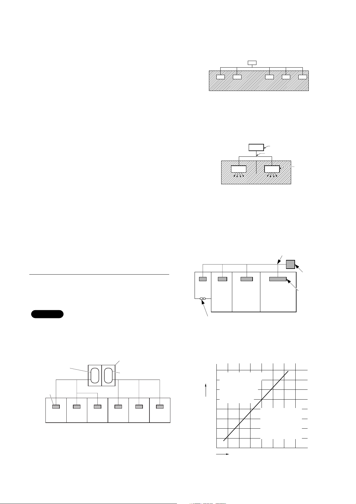
2. The standards for minimum room volume are as
follows.
(1) No partition (shaded portion)
(2) When there is an effective opening with the adja-
cent room for ventilation of leaking refrigerant gas
(opening without a door, or an opening 0.15% or
larger than the respective floor spaces at the top
or bottom of the door).
(3) If an indoor unit is installed in each partitioned
room and the refrigerant tubing is interconnected,
the smallest room of course becomes the object.
But when mechanical ventilation is installed interlocked with a gas leakage detector in the smallest
room where the density limit is exceeded, the volume of the next smallest room becomes the object.
3. The minimum indoor floor space compared with the
amount of refrigerant is roughly as follows: (When
the ceiling is 2.7 m high)
Check of Density Limit
The room in which the air conditioner is to be
installed requires a design that in the event of
refrigerant gas leaking out, its density will not
exceed a set limit.
The refrigerant (R410A), which is used in the air conditioner, is safe, without the toxicity or combustibility of
ammonia, and is not restricted by laws imposed to protect the ozone layer. However, since it contains more
than air, it poses the risk of suffocation if its density
should rise excessively. Suffocation from leakage of
refrigerant is almost non-existent. With the recent
increase in the number of high density buildings, however, the installation of multi air conditioner systems is
on the increase because of the need for effective use
of floor space, individual control, energy conservation
by curtailing heat and carrying power, etc.
Most importantly, the multi air conditioner system is
able to replenish a large amount of refrigerant compared to conventional individual air conditioners. If a
single unit of the multi air conditioner system is to be
installed in a small room, select a suitable model and
installation procedure so that if the refrigerant accidentally leaks out, its density does not reach the limit
(and in the event of an emergency, measures can be
made before injury can occur).
In a room where the density may exceed the limit,
create an opening with adjacent rooms, or install
mechanical ventilation combined with a gas leak
detection device. The density is as given below.
Total amount of refrigerant (kg)
Min. volume of the indoor unit installed room (m3)
≤ Density limit (kg/m
3
)
The density limit of refrigerant which is used in multi air conditioners is 0.3 kg/m
3
(ISO 5149).
1. If there are 2 or more refrigerating systems in a single refrigerating device, the amount of refrigerant
should be as charged in each independent device.
For the amount of charge in this example:
The possible amount of leaked refrigerant gas in rooms
A, B and C is 10 kg.
The possible amount of leaked refrigerant gas in rooms
D, E and F is 15 kg.
Outdoor unit
Refrigerant tubing
Indoor unit
Refrigerant tubing
NOTE
e.g., charged
amount (10 kg)
Indoor unit
Room A Room B Room C Room D Room E Room F
Outdoor unit
e.g., charged
amount (15 kg)
Outdoor unit
Very
small
room
Small
room
Mechanical ventilation device – Gas leak detector
Medium
room
Large room
Indoor unit
40
Range below the
2
35
m
density limit
of 0.3 kg/m
30
(countermeasures
not needed)
25
20
15
10
5
Min. indoor floor space
0
3
10 20 30
Total amount of refrigerant
Range above
the density limit
of 0.3 kg/m
(countermeasures
needed)
3
kg
Page 4
1. GENERAL
This booklet briefly outlines where and how to install the air conditioning system. Please read over the entire set of
instructions for the indoor unit and make sure all accessory parts listed are with the system before beginning.
1-2. Type of Copper Tube and Insulation Material
If you wish to purchase these materials separately
from a local source, you will need:
1. Deoxidized annealed copper tube for refrigerant
tubing.
2. Foamed polyethylene insulation for copper tubes as
required to precise length of tubing. Wall thickness
of the insulation should be not less than 8 mm.
3. Use insulated copper wire for field wiring. Wire
size varies with the total length of wiring. Refer to
4. Electrical Wiring for details.
1-3. Additional Materials Required for Installation
1. Refrigeration (armored) tape
2. Insulated staples or clamps for connecting wire
(See your local codes.)
3. Putty
4. Refrigeration tubing lubricant
5. Clamps or saddles to secure refrigerant tubing
6. Scale for weighing
Check local electrical codes
and regulations before
obtaining wire. Also, check
any specified instructions
or limitations.
4
IMPORTANT . . . . . . . . . . . . . . . . . . . . . . . . . . . . . . 2
Please Read Before Starting
Check of Density Limit
1. GENERAL . . . . . . . . . . . . . . . . . . . . . . . . . . . . . 4
1-1. Tools Required for Installation (not supplied)
1-2. Type of Copper Tube and Insulation Material
1-3. Additional Materials Required for Installation
2. HOW TO INSTALL THE UNIT . . . . . . . . . . . . . .5
2-1. Duct for fresh air
3. TEST OF THE SYSTEM AND CONTROL OF THE
AIR VOLUME TO THE OUTLET GRILLES . . . .7
CONTENTS
Page
Page
1-1. Tools Required for Installation (not supplied)
1. Standard screwdriver
2. Phillips head screwdriver
3. Knife or wire stripper
4. Tape measure
5. Carpenter’s level
6. Sabre saw or key hole saw
7. Hacksaw
8. Core bits
9. Hammer
10. Drill
11. Tube cutter
12. Tube flaring tool
13. Torque wrench
14. Adjustable wrench
15. Reamer (for deburring)
4. ELECTRICAL WIRING . . . . . . . . . . . . . . . . . . . .8
4-1. General Precautions on Wiring
4-2. Recommended Wire Length and Wire Diame-
ter for Power Supply System
4-3. Wiring System Diagrams
5. HOW TO PROCESS TUBING . . . . . . . . . . . . . .12
5-1. Connecting the Refrigerant Tubing
5-2. Connecting Tubing between Indoor and Out-
door Units
5-3. Insulating the Refrigerant Tubing
5-4. Taping the Tubes
5-5. Finishing the Installation
6 APPENDIX . . . . . . . . . . . . . . . . . . . . . . . . . . . .16
CAUTION
Page 5
5
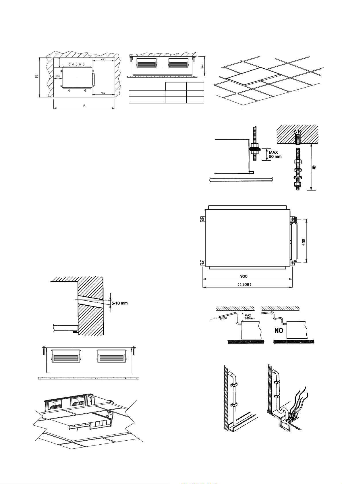
2. HOW TO INSTALL THE UNIT
Fig. 2-1
Minimum operation and maintenance area. (fig. 2-1)
Fig. 2-2
Fig. 2-4
Find the space for the installation of the return air grille and
mark the opening to do. Cut the falseceiling. (fig. 2-2)
Use rawl plug suitable to the ceiling consistence and four
M10 threaded bars of suitable length (not supplied). (fig. 2-
3)
Mark on the ceiling the holes for the hanging rods, verify the
distance of the centres. The value included in the brackets
is referred to the model X18. (fig. 2-4)
Drill a 80 mm diameter hole, for the passage of refrigeration
pipework, condensate pipework and electrical cable. Insert
a PVC pipe in the wall. (fig. 2-5)
Secure the unit in position with locknuts and washers, level
the unit, keeping the right distance from the falseceiling for
the installation of return air grille. (fig. 2-6)
Foresee a removable panel of the falseceiling for servicing.
(fig. 2-7)
The unit is supplied with PVC hose from the condensate
pump. Maximum pump lift is 250 mm over the unit. Convoy
the condensate with a positive slope (min. 1:100) to the outside. The highest point in the condensate pipework should
be as close to the unit as possible. This prevents a large
volume of water draining back into the unit when it is
switched off. (fig. 2-8)
Convoy the condensate to the outside with a positive slope,
from a trap at the end if necessary. (fig. 2-9)
300
Fig. 2-3
Fig. 2-5
Fig. 2-6
Fig. 2-7
Fig. 2-8
Fig. 2-9
7/9/12 1500 1100
16/18/22 1700 1100
AB
Page 6
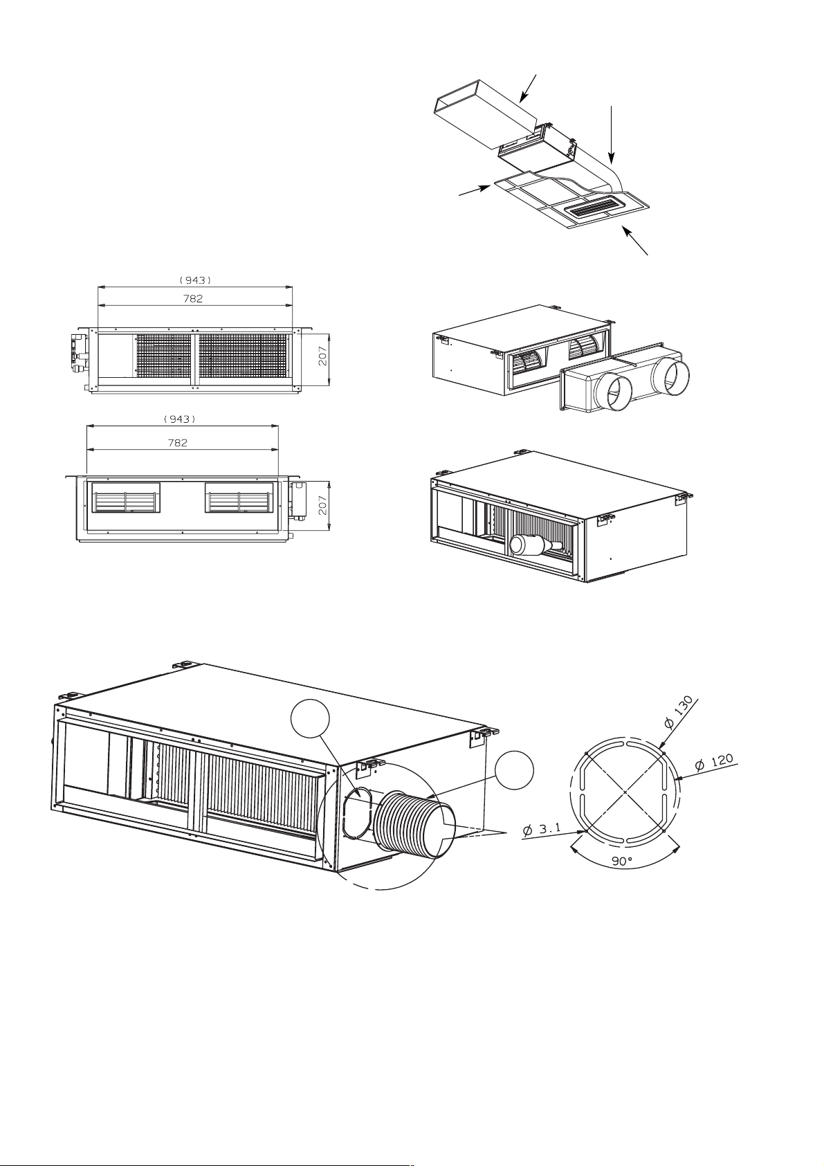
6
Intake coduct
False ceiling
Air intake
Outlet conduct
On the front and rear side of the unit a rectangular port
(with flange) helps during duct mounting. (fig. 2-10)
Rear and front flange for the air intake. The value included
in the brackets is referred to the model X18. (fig. 2-11)
Discarge air duct (optional accessory).
Contact the After Sale Service. (fig. 2-12)
Remove the filter and pour, inside the condensate drain
pan, 0.5 liter of water. Start the unit checking for proper
drain pump operation. (fig. 2-13)
Fig. 2-10
Fig. 2-11
Fig. 2-12
Fig. 2-13
2
1
There is a duct connection port for drawing in fresh air.
The supplementary fan motor for outside air intake has to be supplied separately and controlled by a bipolar ON-OFF switch
with safety fuses.
Fresh air flow must be about 10% of the total air flow to avoid operating problems and noise.
•
Open the knock-out hole , fix a 120 mm flange on the unit and connect the thermically insulated duct.
•
Install an outside grille with filter inspection port to prevent dust and leaves from entering and fouling the indoor unit heat
exchanger.
2-1 Duct for fresh air
Page 7
7
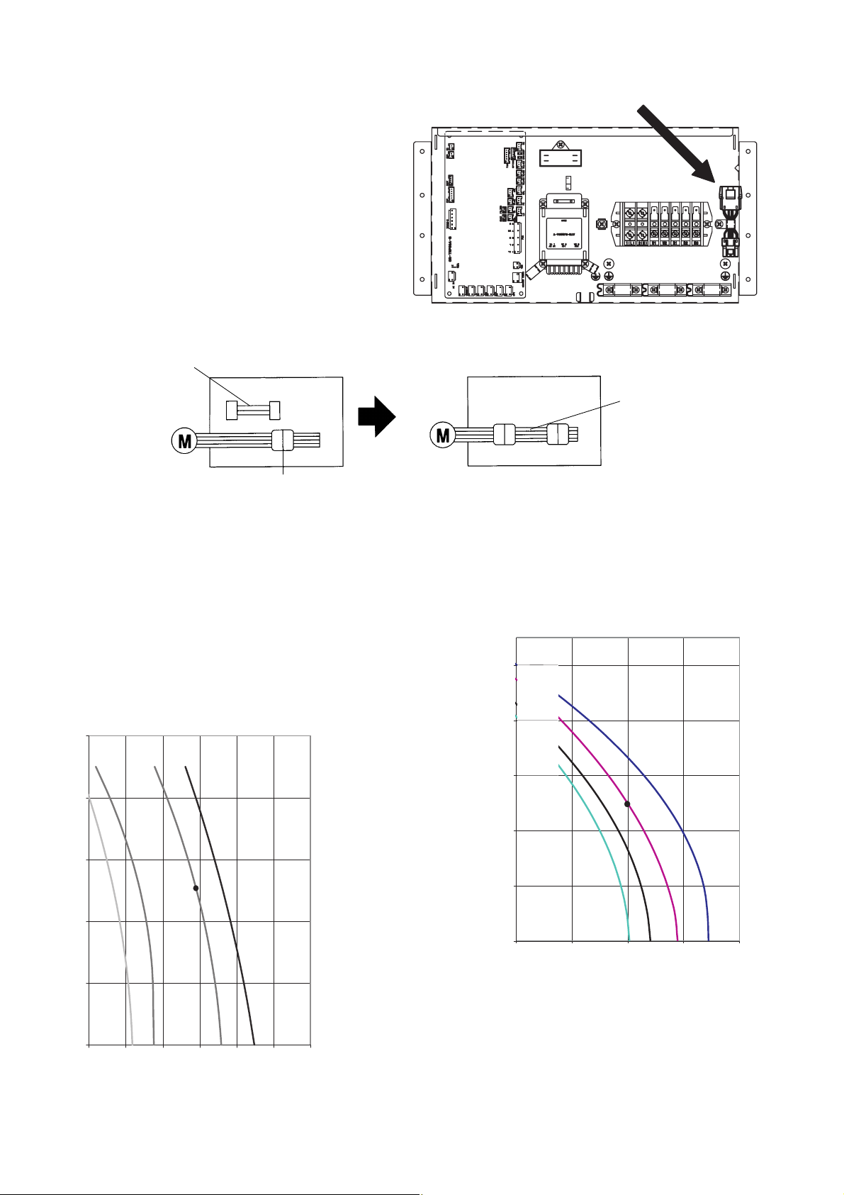
3. TEST OF THE SYSTEM AND CONTROL OF THE AIR VOLUME TO THE OUTLET GRILLES
The unit is prearranged to supply an external static pressure
of about 5 mm. Too high resistances in the air distribution
system can cause an exceedingly small air volume to the
outlet grilles.
This trouble can be solved by increasing the fan speed as
follows:
Open the cover of the electrical junction box. Take out the
booster cable clamped in the box. (fig. 3-1)
Disconnect the fan motor plug in the electrical box and insert
the booster cable as a cable extension between the motor
plug and the socket from the PCB. The external static pressure will increase to 7 mm w.g. Check static pressure and air
flow rate on the fan performance graph. (fig. 3-2)
Fan motor
Fan motor
Booster cable
Booster cable
Connector motor cable (at the supply)
Fig. 3-1
Fig. 3-2
0
2
4
6
8
10
200 400 600 800 1000
H
HH
M
L
7/9/12
16/18/22
m3/h
m
3
/h
EXTERNAL STATIC PRESSURE (mmW.G.)
EXTERNAL STATIC PRESSURE (mmW.G.)
H = High fan speed
L = Low fan speed
HH = Very high fan speed
M = Middle fan speed
H: Standard supplied unit. Available fan speeds: Low-Midd-
le-High (L - M - H). Max. static pressure: about 5 mm
HH: Unit with cable extension of the fan motor (booster
cable). Available fan speeds: Middle-High-Very high (M H - HH). Max. static pressure: about 7 mm
10
8
6
4
2
0
300 500 700 900 1100 1300 1500
M
L
HH
H
Page 8
8
4. ELECTRICAL WIRING
4-1. General Precautions on Wiring
(1) Before wiring, confirm the rated voltage of the unit
as shown on its nameplate, then carry out the
wiring closely following the wiring diagram.
(2) Provide a power outlet to be used exclusively for
each unit, and a power supply disconnect and circuit breaker for overcurrent protection should be
provided in the exclusive line.
(3) To prevent possible hazards from insulation fail-
ure, the unit must be grounded.
(4) Each wiring connection must be done in accor-
dance with the wiring system diagram. Wrong
wiring may cause the unit to misoperate or
become damaged.
(5) Do not allow wiring to touch the refrigerant tubing,
compressor, or any moving parts of the fan.
(6) Unauthorized changes in the internal wiring can be
very dangerous. The manufacturer will accept no
responsibility for any damage or misoperation that
occurs as a result of such unauthorized changes.
(7) Regulations on wire diameters differ from locality
to locality. For field wiring rules, please refer to
your LOCAL ELECTRICAL CODES before beginning.
You must ensure that installation complies with all
relevant rules and regulations.
(8) To prevent malfunction of the air conditioner
caused by electrical noise, care must be taken
when wiring as follows:
● The remote control wiring and the inter-unit control
wiring should be wired apart from the inter-unit
power wiring.
● Use shielded wires for inter-unit control wiring
between units and ground the shield on both sides.
(9) If the power supply cord of this appliance is dam-
aged, it must be replaced by a repair shop
appointed by the manufacture, because special
purpose tools are required.
4-2. Recommended Wire Length and Wire Diameter for Power Supply System
* With ring-type wire terminal.
Outdoor unit
(A) Power supply
Wire size Max. length
2
SPW-CR604GDXH8 113 m 15 A
SPW-CR704GDXH8 74 m 30 A
SPW-CR904GDXH8 60 m 35 A
SPW-CR1154GDXH8 55 m 40 A
SPW-CR704GDCH8 47 m 35 A
SPW-CR904GDCH8 46 m 40 A
SPW-CR1154GDCH8
4 mm
6 mm
6 mm
6 mm
6 mm
6 mm
6 mm
2
2
2
2
2
2
39 m 50 A
Time delay fuse or
circuit capacity
Indoor unit
(B) Power supply
2.5 mm
Max. 130 m
Time delay fuse or
2
circuit capacity
10 ~ 16A
Control wiring
(C) Inter-unit (between outdoor and
(D) Remote control wiring (E) Control wiring for group control
indoor units) control wiring
0.75 mm
2
(AWG #18)
0.75 mm
2
(AWG #18)
Use shielded wiring* Use shielded wiring Use shielded wiring
Max. 1,000 m
Max. 500 m
or
(A) Power supply
Wire size Max. length
2.5 mm
6 mm
6 mm
10 mm
6 mm
10 mm
10 mm
2
70 m
2
74 m
2
60 m
2
91 m
2
47 m
2
77 m
2
65 m
0.75 mm
2
(AWG #18)
Max. 500 m (Total)
Time delay fuse or
circuit capacity
16A
35A
35A
50A
35A
50A
50A
NOTE
(F) Inter-outdoor unit control wiring
2
0.75 mm
(AWG #18)
Use shielded wiring
Max. 500 m
Page 9
9
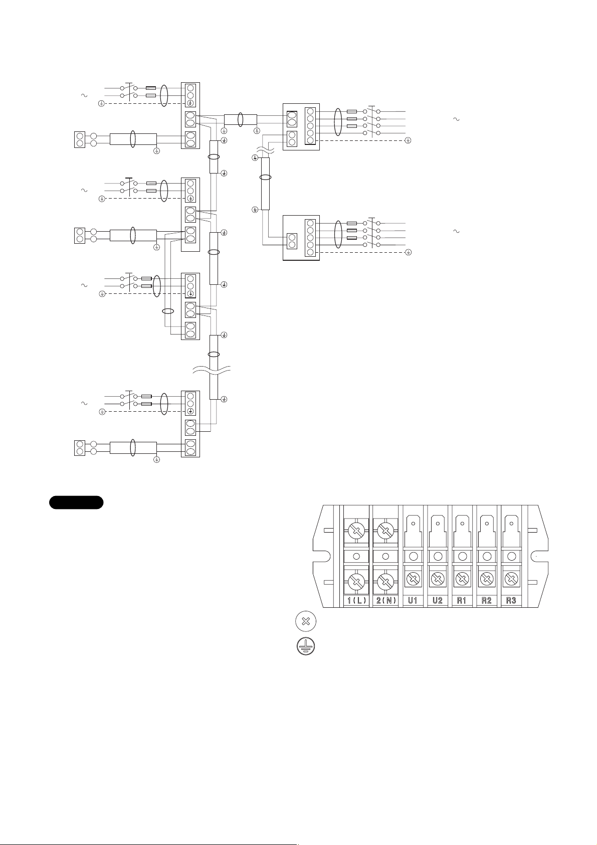
4-3. Wiring System Diagrams
(1) Refer to Section 5-2. “Recommended Wire Length
and Wire Diameter for Power Supply System” for
the explanation of “A,” “B,” “C,” “D,” and “E,” in the
above diagrams.
(2) The basic connection diagram of the indoor unit
shows the 7P terminal board, so the terminal
boards in your equipment may differ from the diagram.
(3) Refrigerant Circuit (R.C.) address should be set
before turning the power on.
7P terminal board
1(L)
power
supply
2(N) U1 U2
Inter-unit
control
wiring
R1 R2
Remote
controller
Power supply
220-240V 50Hz
Remote
controller
WHT
BLK
Power supply
220-240V 50Hz
Remote
controller
WHT
BLK
Group control:
Power supply
220-240V 50Hz
L
N
Ground
B
D
1
1
2
2
L
N
Ground
B
D
1
1
2
2
L
N
Ground
B
E
Indoor
unit (No. 1)
1
2
U1
U2
R1
R2
Indoor
unit (No. 2)
1
2
U1
U2
R1
R2
Indoor
unit (No. 3)
1
2
U1
U2
R1
R2
Outdoor unit
C
Ground
Ground
C
U1
U2
3
4
INV unit
A
1
2
3
4
5
L1
L2
L3
N
Ground
Power supply
380-415V-3N 50Hz
Ground
F
Inter-outdoor-unit control wiring
Outdoor unit
CS unit
Ground
C
3
4
A
1
2
3
4
5
L1
L2
L3
N
Ground
Power supply
380-415V-3N 50Hz
Ground
C
Indoor
Power supply
220-240V 50Hz
Remote
controller
1
WHT
BLK
1
2
2
L
N
Ground
D
unit (No. n)
B
1
2
U1
U2
R1
R2
Ground
NOTE
Page 10
10
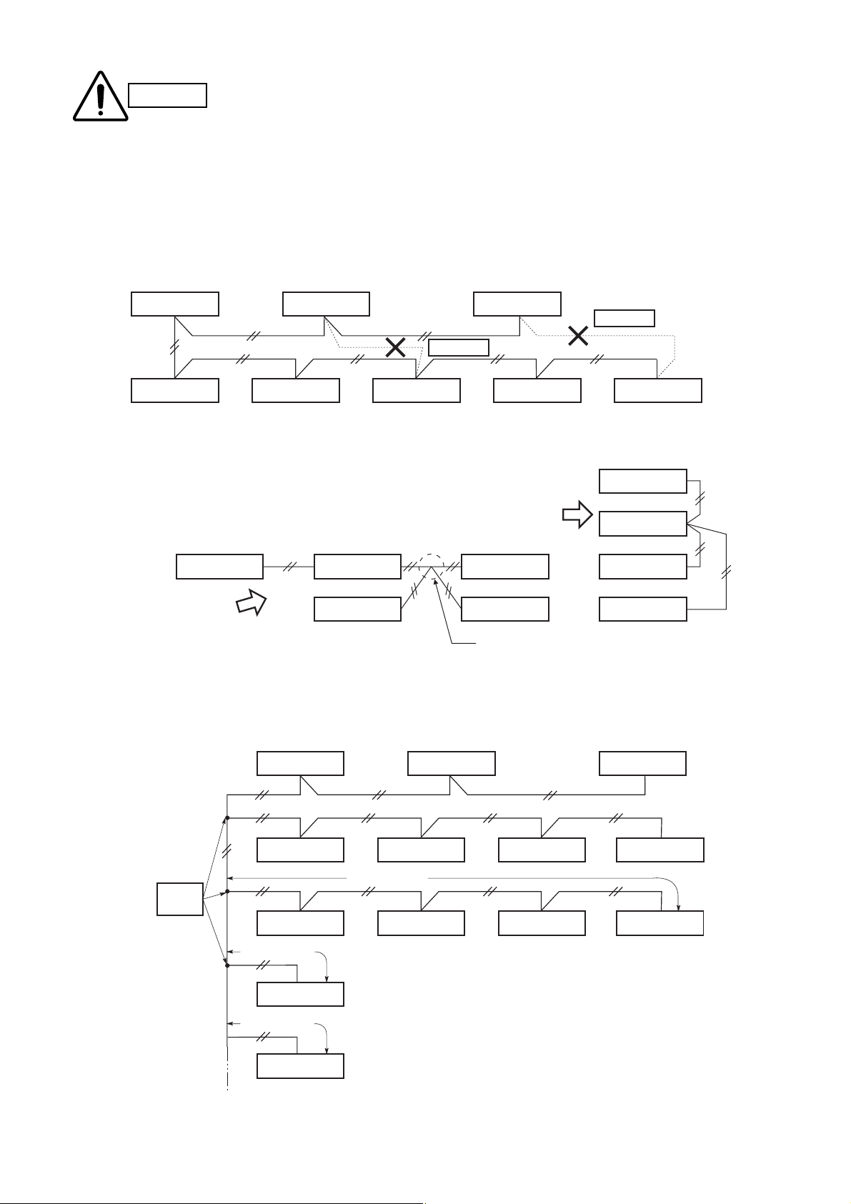
(1) When linking outdoor units in a network (S-net link system), disconnect the terminal extended from the
short plug (CN003, 2P Black, location: right bottom on the outdoor main control PCB) from all outdoor
units except any one of the outdoor units.
(When shipping: In shorted condition.)
Otherwise the communication of S-net link system is not performed. For a system without link (no connection wiring between outdoor units), do not remove the short plug.
(2) Do not install the inter-unit control wiring in a way that forms a loop. (Fig. 4-1)
Fig. 4-1
Fig. 4-2
Fig. 4-3
CAUTION
(3) Do not install inter-unit control wiring such as star
branch wiring. Star branch wiring causes mis-address
setting.
(4) If branching the inter-unit control wiring, the number of branch points should be 16 or fewer.
(Branches less than 1 m are not included in the total branch number.) (Fig. 4-3)
Outdoor unit Outdoor unit Outdoor unit
Prohibited
Indoor unit Indoor unit Indoor unit Indoor unit Indoor unit
NO
Outdoor unit Indoor unit Indoor unit Indoor unit
NO
Indoor unit Indoor unit Indoor unit
Branch point
Prohibited
Outdoor unit
Indoor unit
Branch
point
16 or fewer
Outdoor unit Outdoor unit Outdoor unit
Indoor unit Indoor unit Indoor unit Indoor unit
more than 1 m
Indoor unit
more than 1 m
Indoor unit
less than 1 m
Indoor unit
Indoor unit Indoor unit Indoor unit
Page 11
11
Fig. 4-4
Fig. 4-5
Fig. 4-6
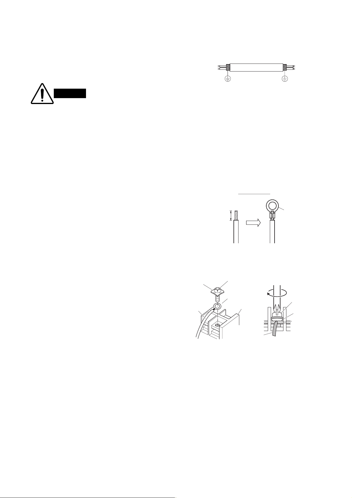
(5) Use shielded wires for inter-unit control wiring
(c) and ground the shield on both sides, otherwise misoperation from noise may occur.
(Fig. 4-4)
Connect wiring as shown in Section “4-3.
Wiring System Diagrams.”
Loose wiring may cause
the terminal to overheat or
result in unit malfunction.
A fire hazard may also
exist. Therefore, ensure
that all wiring is tightly
connected.
When connecting each power wire to the terminal, follow the instructions on “How to connect wiring to the
terminal” and fasten the wire securely with the fixing
screw of the terminal plate.
How to connect wiring to the terminal
■ For stranded wiring
(1) Cut the wire end with cutting pliers, then strip the
insulation to expose the stranded wiring about 10
mm and tightly twist the wire ends. (Fig. 4-5)
(2) Using a Phillips head screwdriver, remove the ter-
minal screw(s) on the terminal plate.
(3) Using a ring connector fastener or pliers, securely
clamp each stripped wire end with a ring pressure
terminal.
(4) Place the ring pressure terminal, and replace and
tighten the removed terminal screw using a screwdriver. (Fig. 4-6)
WARNING
Special
washer
Wire
Ground
Strip 10 mm
Screw
Ring pressure
terminal
Terminal plate
Shielded wire
Ground
Stranded wire
Ring
pressure
terminal
Screw and
Special washer
Ring
pressure
terminal
Wire
Page 12

12
5. HOW TO PROCESS TUBING
The narrow tubing side is connected by a flare nut,
and the wide tubing side is connected by brazing.
5-1. Connecting the Refrigerant Tubing
Use of the Flaring Method
Many of conventional split system air conditioners
employ the flaring method to connect refrigerant tubes
which run between indoor and outdoor units. In this
method, the copper tubes are flared at each end and
connected with flare nuts.
Flaring Procedure with a Flare Tool
(1) Cut the copper tube to the required length with a
tube cutter. It is recommended to cut approx. 30
– 50 cm longer than the tubing length you estimate.
(2) Remove burrs at the end of the copper tube with a
tube reamer or file. This process is important and
should be done carefully to make a good flare.
(Fig. 5-1)
When reaming, hold the tube end downward and be
sure that no copper scraps fall into the tube. (Fig. 5-2)
(3) Remove the flare nut from the unit and be sure to
mount it on the copper tube.
(4) Make a flare at the end of copper tube with a
flare tool.* (Fig. 5-3)
(*Use “RIGID
®
” or equivalent.)
A good flare should have the following characteristics:
● inside surface is glossy and smooth
● edge is smooth
● tapered sides are of uniform length
NOTE
NOTE
Fig. 5-1
Fig. 5-2
Fig. 5-3
Before
Deburring
After
Copper
tubing
Reamer
Flare nut
Copper
tubing
Flare tool
Page 13

13
Caution Before Connecting Tubes Tightly
(1) Apply a sealing cap or water-proof tape to prevent
dust or water from entering the tubes before they
are used.
(2) Be sure to apply refrigerant lubricant to the match-
ing surfaces of the flare and union before connecting them together. This is effective for reducing
gas leaks. (Fig. 5-4)
(3) For proper connection, align the union tube and
flare tube straight with each other, then screw in
the flare nut lightly at first to obtain a smooth
match. (Fig. 5-5)
● Adjust the shape of the narrow tube (liquid tube)
using a tube bender at the installation site and
connect it to the narrow tubing side (liquid tubing
side) valve using a flare.
Cautions During Brazing
● Replace air inside the tube with nitrogen gas to
prevent copper oxide film from forming during
the brazing process. (Oxygen, carbon dioxide
and Freon are not acceptable.)
● Do not allow the tubing to get too hot during
brazing. The nitrogen gas inside the tubing
may overheat, causing refrigerant system
valves to become damaged. Therefore allow
the tubing to cool when brazing.
● Use a reducing valve for the nitrogen cylinder.
● Do not use agents intended to prevent the for-
mation of oxide film. These agents adversely
affect the refrigerant and refrigerant oil, and
may cause damage or malfunctions.
5-2. Connecting Tubing Between Indoor and Out-
door Units
(1) Tightly connect the indoor-side refrigerant tubing
extended from the wall with the outdoor-side tubing.
(2) To fasten the flare nuts, apply specified torque as
at right:
● When removing the flare nuts from the tubing con-
nections, or when tightening them after connecting
the tubing, be sure to use 2 monkey wrenches or
spanners as shown. (Fig. 5-6)
If the flare nuts are over-tightened, the flare may be
damaged, which could result refrigerant leakage
and cause in injury or asphyxiation to room occupants.
● For the flare nuts at tubing connections, be sure to
use the flare nuts that were supplied with the unit,
or else flare nuts for R410A (type 2). The refrigerant tubing that is used must be of the correct wall
thickness as shown in the table at right.
Fig. 5-4
Fig. 5-5
Fig. 5-6
Because the pressure is approximately 1.6 times
higher than conventional refrigerant pressure, the
use of ordinary flare nuts (type 1) or thin-walled
tubes may result in tube rupture, injury, or asphyxiation caused by refrigerant leakage.
● In order to prevent damage to the flare caused by
over-tightening of the flare nuts, use the table
above as a guide when tightening.
● When tightening the flare nut on the narrow tube,
use a monkey wrench with a nominal handle length
of 200 mm.
Indoor unit
Tube diameter
φ
6.35 (1/4")
φ
9.52 (3/8")
φ
12.7 (1/2")
φ
15.88 (5/8")
Apply refrigerant
lubricant here and here
Union
Flare nut
Torque wrench
Outdoor unit
Tightening torque,
approximate
14 – 18 N
(140 – 180 kgf
34 – 42 N
(340 – 420 kgf
49 – 61 N
(490 – 610 kgf
68 – 82 N
(680 – 820 kgf
m
·
cm)
·
m
·
cm)
·
m
·
cm)
·
m
·
cm)
·
Spanner
Tube thickness
0.8 mm
0.8 mm
0.8 mm
1.0 mm
Page 14
14
Fig. 5-8
Fig. 5-7
Fig. 5-9
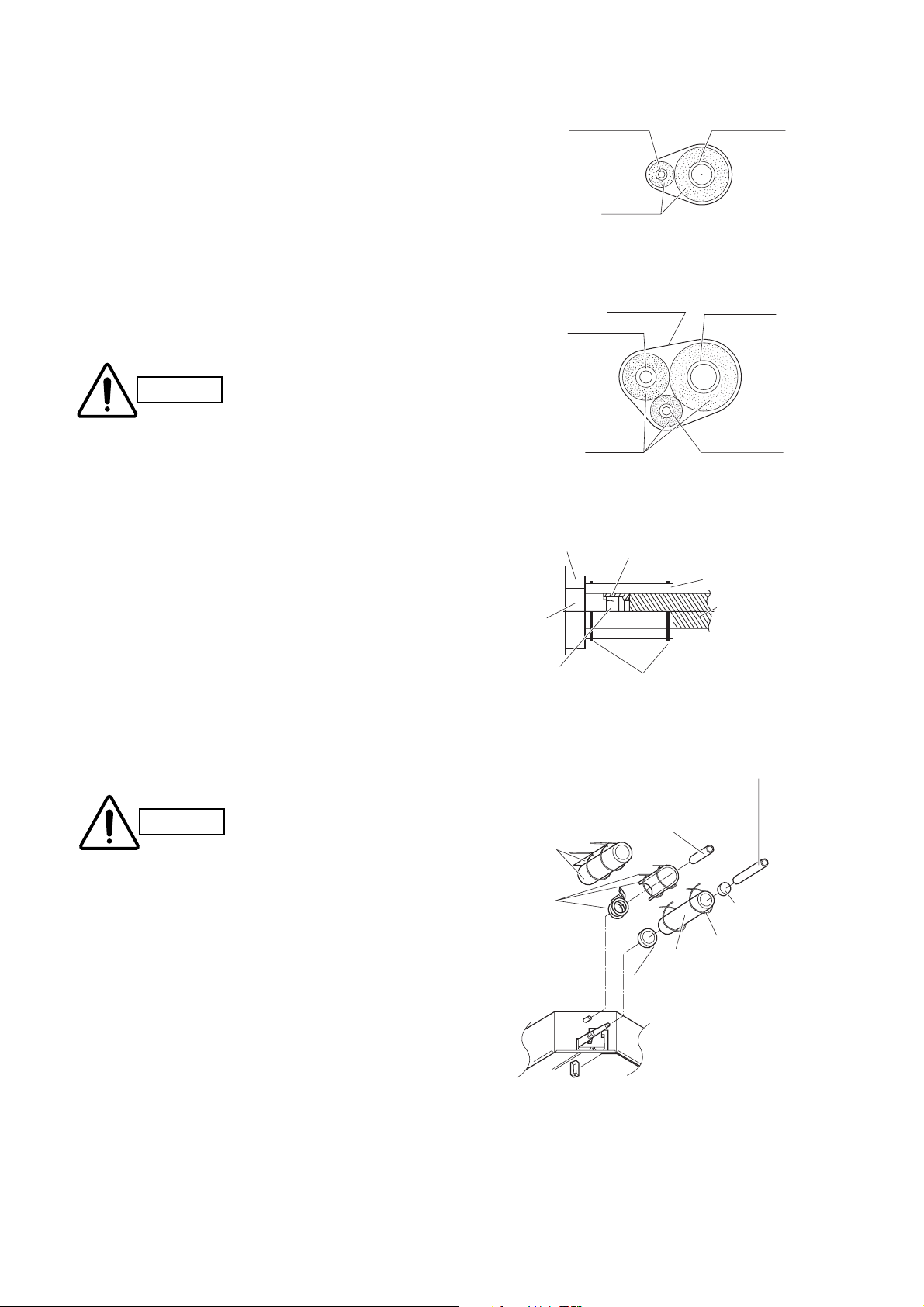
5-3. Insulating the Refrigerant Tubing
Tubing Insulation
● Thermal insulation must be applied to all unit tub-
ing, including distribution joint (purchased separately).
* For gas tubing, the insulation material must be
heat resistant to 120°C or above. For other tubing,
it must be heat resistant to 80°C or above.
Insulation material thickness must be 10 mm or
greater.
If the conditions inside the ceiling exceed DB 30°C
and RH 70%, increase the thickness of the gas
tubing insulation material by 1 step.
Taping the flare nuts
Wind the white insulation tape around the flare nuts at
the wide tube connections. Then cover up the tubing
connections with the flare insulator, and fill the gap at
the union with the supplied black insulation tape.
Finally, fasten the insulator at both ends with the supplied vinyl clamps. (Fig. 5-8)
Insulation material
The material used for insulation must have good insulation characteristics, be easy to use, be age resistant, and must not easily absorb moisture.
After a tube has been insulated, never try to bend it
into a narrow curve
because it can cause the
tube to break or crack.
Never grasp the drain or refrigerant connecting
outlets when moving the unit.
y
Three tubes arranged together
Two tubes arranged together
If the exterior of the outdoor
unit valves has been finished
with a square duct covering,
make sure you allow sufficient space to use the valves
and to allow the panels to be
attached and removed.
CAUTION
Narrow tubing
Sealer (supplied)
Unit side
insulator
Flare nut
Narrow tubing
Insulation
Cosmetic
(finishing) tape
Insulation
Insulation tape (white)
(supplied)
Vin
Wide tubing
Wide tubing
Balance tubing
Flare insulator (supplied)
Tube insulator
(not supplied)
Heat resistant
120°C or above
l clamps (supplied)
CAUTION
Refrigerant tubing and insulator
Drain insulator
and clamp.
Large
(supplied)
Packing
clamp.
Small
hose band
(supplied)
(not supplied)
Drain pipe and insulator
(not supplied)
Insulation
tape
Vinyl
Flare
clamp
insulator
Seal
The procedure used for
installing the insulator for
both wide and narrow
tubes is the same.
Page 15

15
Fig. 5-10
Fig. 5-11
5-4. Taping the Tubes
(1) At this time, the refrigerant tubes (and electrical
wiring if local codes permit) should be taped
together with armoring tape in 1 bundle. To prevent the condensation from overflowing the drain
pan, keep the drain hose separate from the
refrigerant tubing.
(2) Wrap the armoring tape from the bottom of the
outdoor unit to the top of the tubing where it
enters the wall. As you wrap the tubing, overlap
half of each previous tape turn.
(3) Clamp the tubing bundle to the wall, using 1
clamp approx. each meter. (Fig. 5-10)
Do not wind the armoring tape too tightly since this
will decrease the heat insulation effect. Also ensure
that the condensation drain hose splits away from the
bundle and drips clear of the unit and the tubing.
5-5. Finishing the Installation
After finishing insulating and taping over the tubing,
use sealing putty to seal off the hole in the wall to prevent rain and draft from entering. (Fig. 5-11)
NOTE
g
Insulated tubes
Clamp
Drain hose
Apply putty here
Tubin
Page 16

6. APPENDIX
1. 2.
■ Name of Parts (Indoor Unit)
Air outlet
Water drain
Air filter
■ Care and Cleaning
1. For safety, be sure to turn the air conditioner off and also to disconnect the power before
WARNING
Air intake and outlet side Clean the air intake and outlet side of the indoor unit with a vacuum cleaner brush, or wipe them
(Indoor unit) with a clean, soft cloth.
cleaning.
2. Do not pour water on the indoor unit to clean it. This will damage the internal components and cause an electric shock hazard.
1. Never use solvents or harsh chemicals when cleaning the indoor unit. Do not wipe plastic
CAUTION
parts using very hot water.
2. Some metal edges and the fins are sharp and may cause injury if handled improperly; be
especially careful when you clean these parts.
3. The internal coil and other components of the outdoor unit must be cleaned every year.
Consult your dealer or service center.
Air filter
The air filter collects dust and other particles from the air and should be cleaned at regular intervals
as indicated in the table below or when the filter indication ( ) on the display of the remote control
unit (wired type) shows that the filter needs cleaning. If the filter gets blocked, the efficiency of the air
conditioner drops greatly.
Type Period
UMR Six months
NOTE
The frequency with which the filter should be cleaned depends on the environment in which the
unit is used.
<How to clean the filter>
1. Remove the air filter from the air intake grille.
2. Use a vacuum cleaner to remove light dust. If there is sticky dust on the filter, wash the
filter in lukewarm, soapy water, rinse it in clean water, and dry it.
16
Page 17

Care: After a prolonged idle period
Care: Before a prolonged idle period
Check the indoor and outdoor unit air intakes and outlets for blockage; if there is a
blockage, remove it.
• Operate the fan for half a day to dry out the inside.
• Disconnect the power supply and also turn off the circuit breaker.
• Clean the air filter and replace it in its original position.
• Outdoor unit internal components must be checked and cleaned periodically. Con-
tact your local dealer for this service.
CAUTION
1. Certain metal edges and the condenser fins are sharp and may cause injury if handled
improperly; special care should be taken when you clean these parts.
2. Periodically check the outdoor unit to see if the air outlet or air intake is clogged with dirt
or soot.
3. The internal coil and other components of the outdoor unit must also be cleaned periodically. Consult your dealer or service center.
■ Troubleshooting
If your air conditioner does not work properly, first check the following points before requesting service. If it still does not work
properly, contact your dealer or a service center.
■ Tips for Energy Saving
Avoid
Do
• Do not block the air intake and outlet of the unit. If either is obstructed, the unit
will not work well, and may be damaged.
• Do not let direct sunlight into the room. Use sunshades, blinds or curtains. If the walls
and ceiling of the room are warmed by the sun, it will take longer to cool the room.
• Always try to keep the air filter clean. (Refer to “Care and Cleaning.”) A clogged filter
will impair the performance of the unit.
• To prevent conditioned air from escaping, keep windows, doors and any other openings closed.
Should the power fail while the unit is running
If the power supply for this unit is temporarily cut off, the unit will automatically resume operation once power is
restored using the same settings before the power was interrupted.
Trouble
Air conditioner does not run at all
1. Power failure.
2. Leakage circuit breaker has
3. Line voltage is too low.
4. Operation button is turned off.
5. The wired remote control unit or
Compressor runs but soon stops
Poor cooling (or heating)
performance
1. Obstr uction in front of condenser
1. Dirty or clogged air filter.
2. Heat source or many people in
3. Doors and/or windows are open.
4. Obstacle near air intake or air
5. Thermostat is set too high for
6. (Defrosting system does not work.)
Possible Cause
tripped.
malfunctioning.
(
The inspection mark and the
H, L, P in
on
(or too low for heating).
combination with numbers
the LCD of the wired
heat pump is
letters E, F,
appear
remote control unit.)
coil
room.
discharge port.
cooling
After a power outage, press ON/
1.
on the
2. Contact service center.
3. Consult your electrician or dealer.
4. Press the button again.
5. Consult your dealer.
1. Remove obstruction
1. Clean air filter to improve the
2. Eliminate heat source if possible.
3. Shut them to keep the heat (or
4. Remove it to ensure good airflow.
5. Set the temperature lower (or
6. (Consult your dealer.)
wired remote control unit.
Remedy
OFF operation
airflow.
cold) out.
higher).
button
NOTE
17
Page 18

■ Nom des pièces (unité intérieure)
1. 2.
Sortie díair
Drain
■ Entretien et nettoyage
1. Pour toute sécurité, éteignez le climatiseur et débranchez-le de la prise secteur.
AVERTISSEMENT
2. Ne versez pas d’eau sur l’unité intérieure pour la nettoyer. Cela pourrait abîmer les composants internes et provoquer des décharges électriques.
Filtre à air
L’arrivée d’air et la sortie d’air
(unité intérieure)
1. Ne utilisez jamais de dissolvants ni de produits chimiques puissants lorsque l’unité
ATTENTION
2. Certains bords métalliques et les ailettes étant coupants, ils doivent être manipulés avec
3. La bobine interne et les autres composants de l’unité extérieure doivent être nettoyés
Filtre à air
Le filtre à air recueille la poussière et les particules se trouvant dans l’air et doit être nettoyé à intervalles réguliers comme indiqué dans le tableau cidessous ou lorsque le symbole du filtre ( )
affiché sur la télécommande (avec fil) indique que le filtre doit être nettoyé. Si le filtre est bloqué,
l’efficacité du climatiseur diminue nettement.
Type Période
UMR Six mois
Nettoyez l’arrivée d’air et la sortie de l’unité intérieure avec la brosse d’un aspirateur ou les
essuyer avec un chiffon propre et doux.
intérieure est nettoyée. N’essuyez pas les pièces en plastique avec de l’eau très chaude.
précaution lors du nettoyage sous peine de provoquer des blessures.
tous les ans. Consultez le concessionnaire ou un service après-vente.
REMARQUE
La fréquence de nettoyage du filtre dépend de l’environnement dans lequel l’unité est utilisée.
<Comment nettoyer le filtre>
1. Retirez le filtre à air de la grille de l’arrivée d’air.
2. Se servir d’un aspirateur pour enlever la poussière légère. Si de la poussière adhère au
filtre, lavez celui-ci dans de l’eau tiède et savonneuse, puis rincez-le dans de l’eau propre
et séchez-le.
18
Page 19

Entretien : après une période d’inactivité
prolongée
Entretien : avant une période d’inactivité
prolongée
Vérifiez l’arrivée d’air et la sortie d’air des unités intérieure et extérieure et
assurez-vous qu’elles ne sont pas obstruées ; si elles sont obstruées, remédiez
à ce problème.
• Faites fonctionner le ventilateur pendant une demi-journée pour faire sécher
l’intérieur de l’unité.
• Débranchez l’alimentation et mettez le disjoncteur en position arrêt.
• Nettoyez le filtre à air et remettez-le dans sa position initiale.
• Les éléments internes de l’unité extérieur doivent être vérifiés et nettoyés
régulièrement. Contactez votre distributeur le plus proche pour effectuer ces
opérations.
ATTENTION
1. Certains bords métalliques et les ailettes du condensateur étant coupants, ils doivent être
manipulés avec précaution lors du nettoyage sous peine de provoquer des blessures.
2. Vérifiez régulièrement que la sortie et l’arrivée d’air ne soient pas obstruées par de la
poussière ou de la suie.
3. La bobine interne et les autres composants de l’unité extérieure doivent être nettoyés
régulièrement. Consultez le concessionnaire ou un service après-vente.
19
Page 20

■ Guide de dépannage
Si le climatiseur ne fonctionne pas correctement, effectuez les vérifications suivantes avant de faire appel à un réparateur. Si le
problème persiste, prenez contact avec votre concessionnaire ou avec un service après-vente.
Panne Cause possible Remède
Le climatiseur ne fonctionne pas du
tout.
Le compresseur se met en marche
mais il s’arrÍte aussitôt.
Refroidissement (ou chauffage)
insuffisant.
1. Coupure de courant. 1. Après une panne de courant,
2. Le disjoncteur a fonctionné. 2. Prenez contact avec un service
3. Tension de ligne trop basse. 3. Consultez un électricien ou le
4. Le bouton de fonctionnement est en
position Off.
5. La télécommande avec fil ou la
pompe thermique ne fonctionne pas
correctement.
(La marque díinspection et les
lettres E, F, H, L, P ainsi que des
numéros apparaissent sur l’affichage
à cristaux liquides de la
télécommande avec fil.)
1. Il y a un obstacle dev ant la bobine du
condensateur.
1. Filtre à air sale ou obstrué. 1. Nettoyez le filtre à air afin
2. Source de chaleur ou trop de monde
dans la pièce.
3. Portes et/ou fenÍtres ouv ertes. 3. Fermez-les pour empÍcher la
4. Obstacle devant l’arrivée ou la sortie
d’air.
5. Le thermostat est réglé sur une
température trop élevée pour le
refroidissement (ou trop basse pour
le chauffage).
6. (Le dégivrage du système ne
fonctionne pas.)
appuyez sur le bouton de marche/
arrêt de fonctionnement de la
télécommande avec fil.
après-vente.
concessionnaire.
4. Appuyez à nouveau sur le bouton.
5. Consultez le concessionnaire.
1. Retirez ce qui fait obstruction.
díaméliorer la circulation díair.
2. Si possible, éliminez la source de
chaleur.
pénétration d’air chaud (ou froid).
4. Retirez líobstacle pour assurer une
bonne circulation d’air.
5. Réglez la température plus bas (ou
plus haut).
6. (Consultez le concessionnaire
.)
■ Conseils pour économiser l’énergie
• Obstruer les arrivées et les sorties d’air de l’appareil. Si elles sont bouchées,
l’appareil ne fonctionnera pas de façon satisfaisante et il risque d’être endommagé.
• Laisser le soleil pénétrer directement dans la pièce. Utiliser des persiennes ou des
rideaux. Si les murs et le plafond de la pièce sont chauds sous l’action du soleil, il faudra
plus longtemps pour refroidir la pièce.
• Toujours maintenir le filtre à air propre. (Voir “Entretien et nettoyage”) Un filtre obstrué
risque d’affecter le fonctionnement de l’unité.
• Pour éviter que l’air refroidi ne s’échappe, maintenir toutes les fenêtres, portes et autres
ouvertures fermées.
REMARQUE
À éviter
Choses à faire
Si une panne de courant se produit lorsque l’unité fonctionne
Si l’alimentation de cette unité est temporairement arrêtée, l’unité se remettra en marche, après rétablissement
de l’alimentation, avec les mêmes réglages qu’avant la panne de courant.
20
Page 21

■ Bezeichnungen der Teile
Luftauslass
■ Care and Cleaning
■ Pflege und Reinigung
1. Aus Sicherheitsgründen darauf achten, das Gerät vor dem Reinigen auszuschalten und
WARNUNG
es außerdem vom Netz zu trennen.
2. Kein Wasser auf die Inneneinheit schütten, um diese zu reinigen. Dadurch werden die
inneren Bauteile beschädigt, und es besteht Stromschlaggefahr.
Wasserablass
Luftfilter
Lufteinlass- und -auslassseite
(Inneneinheit)
1. Verwenden Sie niemals Lösungsmittel oder starke Chemikalien, um die Inneneinheit zu
VORSICHT
2. Gewisse Metallkanten und die Kondensatorrippen sind scharf und können Verletzungen
3. Die innere Wärmeaustauscherschlange und andere Bauteile der Außeneinheit müssen
Luftfilter
Der Luftfilter sammelt Staub und andere Teilchen aus der Luft und sollte in regelmäßigen Abständen
gereinigt werden, wie in der Tabelle unten angezeigt, bzw. wenn die Filteranzeige ( ) auf dem Dis-
play der (verdrahteten) Fernbedienung anzeigt, dass der Filter gereinigt werden sollt. Falls der Filter
verstopft ist, nimmt der Wirkungsgrad des Klimageräts stark sb.
Typ Zeitraum
UMR Sechs Monate
Reinigen Sie die Lufteinlass- und -auslassseite der Inneneinheit mit einer Staubsaugerbürste bzw. wischen Sie sie mit einem sauberen weichen Tuch ab.
reinigen. Wischen Sie die Plastikteile nicht mehr sehr heißem Wasser ab.
verursachen, wenn sie nicht richtig gehandhabt werden; beim Reinigen dieser Teile
besonders vorsichtig sein.
einmal im Jahr gereinigt werden. Wenden Sie sich dazu bitte an Ihren Fachhändler oder
an eine Kundendienststelle.
ZUR BEACHTUNG
Die Häufigkeit der Luftfilterreinigung hängt von der Umgebung, in der der Luftfilter verwendet
wird, ab.
<Reinigen des Luftfilters>
1. Nehmen Sie den Luftfilter aus dem Lufteinlassgitter.
2. Einen Staubsauger verwenden, um leichten Staub zu entfernen. Wenn klebriger Staub
am Filter anhaftet, diesen in lauwarmer Seifenlauge auswaschen, mit sauberem Wasser
abspülen und trocknen lassen.
21
Page 22

Pflege: Wenn das Gerät über längere
Zeit nicht verwendet wurde
Pflege: Wenn das Gerät über längere
Zeit nicht verwendet werden soll
Überprüfen Sie Lufteinlässe und -auslässe der Innen- und der Außeneinheit auf
Verstopfung; ist eine Verstopfung vorhanden, entfernen Sie sie.
• Lassen Sie das Getriebe einen halben Tag lang laufen, um das Innere des
Geräts zu trocknen.
• Schalten Sie die Stromversorgung des Geräts aus; schalten Sie dann auch
den Trennschalter aus.
• Reinigen Sie den Luftfilter und setzen Sie ihn dann erneut an seiner Ausgangsposition ein.
• Die Innenbauteile der Außeneinheit müssen regelmäßig überprüft und gereinigt werden. Lassen Sie diese Arbeiten von Ihrem Fachhändler durchführen.
1. Gewisse Metallkanten und die Kondensatorrippen sind scharf und können Verletzungen
verursachen, wenn Sie nicht richtig gehandhabt werden. Seien Sie daher beim Reinigen
dieser Teile besonders vorsichtig.
2. Überprüfen Sie die Außeneinheit regelmäßig, um zu sehen, ob Luftauslass oder Lufteinlass mit Staub oder Ruß verstopft sind.
3. Die innere Wärmeaustauscherschlange und andere Bauteile der Außeneinheit müssen
ebenfalls regelmäßig gereinigt werden. Wenden Sie sich dazu bitte an Ihren Fachhändler
oder an eine Kundendienststelle.
VORSICHT
1. 2.
22
Page 23

■ Fehlersuche
Wenn Ihr Klimagerät nicht richtig funktioniert, zuerst die folgenden Punkte überprüfen, bevor ein Kundendiensttechniker angefordert wird. Läßt sich die Störung nicht beheben, so wenden Sie sich bitte an Ihren Fachhändler oder an eine Kundendienststelle.
Störung Mögliche Ursache Abhilfe
Das Klimagerät läuft überhaupt
nicht.
1. Keine Stromzufuhr. 1.
2. Der Fehlerstromschutzschalter
wurde ausgelöst.
3. Netzspannung ist zu niedrig. 3. Lassen Sie sich von Ihrem Elektriker
4. Die Betriebstaste ist ausgeschaltet. 4. Die Taste erneut drücken.
5. Fehlfunktion der verdrahtete
Fernbedienung oder der Wärmepumpe.
(
Das Überprüfungszeichen und
die Buchstaben E, F , H, L, P
zusammen mit Zahlen werden auf
der LCD-Anzeige der verdrahtete
Fernbedienung angezeigt.)
Kompressor läuft, kommt jedoch
bald zum Stillstand.
Schlechte Kühl- oder Heizleistung 1. Luftfilter ist schmutzig oder
1. Ein Hindernis befindet sich vor der
Kondensatorschlange.
zugesetzt.
2. Eine Wärmequelle oder viele Leute
befinden sich im Raum.
3. Türen und/oder Fenster sind
geöffnet.
4.
Ein Hindernis befindet sich in der
Nähe von Lufteinlass oder
Luftauslass.
5. Der Thermostat ist zu hoch zum
Kühlen eingestellt (bzw. zu niedrig
zum Heizen).
6. (Abtausystem funktioniert nicht.) 6. (Lassen Sie sich von Ihrem
Drücken Sie nach einem Stromausfall
die Betriebstaste (ON/OFF) auf der
verdrahteten Fernbedienung.
2. Wenden Sie sich an eine
Kundendienststelle.
oder Fachhändler beraten.
5. Lassen Sie sich von Ihrem
Fachhändler beraten.
1. Hindernis entfernen.
1. Luftfilter reinigen, um den Luftstrom
zu verbessern.
2. Die Wärmequelle möglichst
abschalten.
3. Diese schlieflen, damit keine Wärme
(bzw. Kälte) von auflen eindringt.
4. Hindernis entfernen, um einen
unbehinderten Luftstrom zu
gewährleisten.
5. Temperatur niedriger (bzw. höher)
einstellen.
Fac
hhändler beraten.)
■ Nützliche Hinweise für Energieeinsparung
Zu vermeiden
ZUR BEACHTUNG
Bei einem Stromausfall während des Betriebs des Geräts
Wird die Stromversorgung dieses Geräts vorübergehend unterbrochen, setzt das Gerät den Betrieb nach
erneuter Stromversorgung automatisch mit denselben Einstellungen wie vor der Unterbrechung der
Stromversorgung fort.
• Blockieren Sie den Lufteinlass und -auslass des Gerätes nicht. Falls der Ein- oder
Auslass blockiert wird, funktioniert das Gerät nicht richtig und kann sogar
beschädigt werden.
• Setzen Sie den Raum nicht direkter Sonnenbestrahlung aus. Markisen, Jalousien oder
Vorhänge verwenden. Wenn die Wände und Decke des Raumes Strahlungswärme von der
Sonne aufnehmen, dauert es länger, den Raum zu kühlen.
Ja
• Den Luftfilter stets sauber halten. (Siehe den Abschnitt „Pflege und Reinigung“.) Ein verstopfter Filter beeinträchtigt die Leistung des Gerätes.
• Um zu verhindern, dass klimatisierte Luft entweicht, Fenster, Türen und andere Öffnungen
außer für Lüftungszwecke geschlossen halten.
23
Page 24

■ Nome delle parti (Unità interna)
1. 2.
Uscita d’aria
Scarico dell’acqua
■ Cura e manutenzione
1. Per motivi di sicurezza, accertare che il condizionatore d’aria sia spento e che la spina
AVVERTIMENTO
del cavo di alimentazione sia staccata dalla presa di corrente prima di procedere con le
operazioni di pulizia.
2. Non versare acqua sull’unità interna per pulirla. Ciò può danneggiare i componenti interni
e causare il pericolo di scosse.
Filtro aria
Lato presa d’aria e uscita
d’aria (unità interna)
1. Per pulire l’unità interna, non si devono usare solventi o sostanze chimiche aggressive.
PRECAUZIONE
2. Alcuni bordi metallici e le alette sono taglienti e possono causare ferite se maneggiati in
3. La serpentina interna e gli altri componenti dell’unità esterna devono essere puliti una
Filtro dell’aria
Il filtro dell’aria raccoglie le particelle di polvere e sporco dall’aria e dovrebbe essere pulito a intervalli
regolari, come indicato nella tabella seguente, oppure quando l’indicazione del filtro ( ) sul display
del telecomando (tipo cablato) non segnala che occorre pulire il filtro. Se il filtro si ostruisce, l’efficienza del condizionatore d’aria ne risulta notevolmente compromessa.
Tipo Periodo
UMR Sei mesi
Pulire il lato della presa d’aria e dell’uscita d’aria dell’unità interna con una spazzola aspirapolvere o con un panno pulito e morbido.
Non pulire i componenti in plastica con acqua molto calda.
modo incorretto. Prestare perciò la dovuta attenzione nel pulire tali parti.
volta all’anno. Rivolgersi al proprio rivenditore o centro di assistenza.
NOTA
La frequenza alla quale occorre pulire il filtro dipende dall’ambiente in cui viene utilizzata l’unità.
<Pulizia del filtro>
1. Rimuovere il filtro dell’aria dalla griglia della presa d’aria.
2. Rimuovere la polvere leggera servendosi di un aspirapolvere. Se la polvere resta attaccata al fil-
tro, lavarlo con acqua saponata tiepida, sciacquarlo con acqua pulita ed asciugarlo.
24
Page 25

Cura: dopo un periodo di
inattività prolungato
Cura: prima di periodo di
inattività prolungato
Controllare le prese d’aria e le uscite d’aria delle unità interna ed esterna, verificando che non
siano ostruite; eliminare eventuali ostruzioni.
• Azionare la ventola per mezza giornata per far asciugare l’interno.
• Scollegare l’alimentazione elettrica e disinserire l’interruttore automatico.
• Pulire il filtro dell’aria e rimetterlo nella sua posizione originale.
• I componenti interni dell’unità esterna vanno controllati e puliti periodicamente. A questo
scopo rivolgersi al proprio rivenditore locale.
1. Alcuni bordi metallici e le alette del condensatore sono taglienti e possono causare ferite
se maneggiati in modo incorretto; occorre pertanto prestare particolare attenzione nel
pulire tali componenti.
2. Controllare periodicamente l’unità esterna, accertando che l’uscita d’aria e la presa d’aria
non siano ostruite da sporco o fuliggine.
3. Anche la bobina interna e altri componenti dell’unità esterna richiedono una pulizia periodica. Rivolgersi al proprio rivenditore o centro di assistenza.
PRECAUZIONE
25
Page 26

■ Prima di chiamare il tecnico
Se il condizionatore d’aria non funziona correttamente, prima di chiamare il tecnico per la riparazione controllare quanto segue.
Se ciò non consente di eliminare il problema, rivolgersi al proprio rivenditore o centro di assistenza.
Problema Causa probabile Rimedio
Il condizionatore d’aria non
funziona.
Il compressore funziona, ma si
arresta subito.
Le prestazioni di raffreddamento
(o di riscaldamento) sono
scarse.
1. Si è verificata una mancanza di corrente. 1.
2. Il salvavita è scattato. 2. Rivolgersi al centro di assistenza.
3. La tensione di rete è insufficiente. 3. Rivolgersi ad un elettricista o al
4. Il pulsante di accensione/spegnimento è
spento.
5. Il telecomando cablato o la pompa di
calore non funziona correttamente.
(Sullo schermo LCD del telecomando
cablato vengono visualizzati il segno di
ispezione e le lettere E, F, H, L, P, in
combinazione con dei numeri).
1. Presenza di un’ostruzione davanti alla
serpentina del condensatore.
1. Il filtro dellíaria è sporco o intasato. 1. Pulire il filtro dell’aria per
2. Nella stanza ci sono una fonte di calore o
molte persone.
3. Ci sono porte o finestre aperte. 3. Chiuderle per mantenere il caldo
4. C’è un ostacolo vicino alla presa d’aria o
all’uscita dell’aria.
5. Il termostato è impostato ad un valore
troppo alto per il raffreddamento (o
troppo basso per il riscaldamento).
6. (Il sistema di sbrinamento non funziona). 6. (Rivolgersi al proprio rivenditore
Dopo una mancanza di
corrente, premere il pulsante di
accensione/spegnimento (ON/
OFF) del telecomando cablato.
proprio rivenditore.
4. Premere nuovamente il pulsante.
5. Rivolgersi al proprio rivenditore.
1. Rimuovere l’ostruzione.
migliorare il getto dell’aria.
2. Se possibile, eliminate la fonte di
calore.
(o il freddo) all’esterno.
4. Rimuoverlo in modo da assicurare
un buon getto d’aria.
5. Impostare la temperatura a un
livello più basso (o più alto).
.)
■ Suggerimenti per risparmiare energia
• Non ostruire la presa d’aria e l’uscita d’aria dell’unità. In caso di ostruzione,
l’unità non funziona correttamente e può subire dei danni.
• Non lasciar entrare la luce solare diretta nella stanza. A tale scopo utilizzare parasole,
tende o persiane. Se le pareti e il soffitto vengono riscaldati dal sole, il raffreddamento
della stanza richiede più tempo.
• Mantenete sempre pulito il filtro dell’aria (fare riferimento a “Cura e manutenzione”). Un
filtro ostruito compromette il rendimento dell’unità.
• Per evitare fughe d’aria condizionata, tenete chiuse finestre, porte ed altre aperture.
NOTA
Da evitare
Cose da fare
Mancanza di corrente durante il funzionamento dell’unità
In caso di una temporanea mancanza di corrente, l’unità riprende automaticamente a funzionare, al ripristino
della corrente, con le stesse impostazioni che aveva prima dell’interruzione.
26
Page 27

■ Nomenclatura das peças (unidade interior)
Saída de ar
Drenagem de água
■ Cuidados e limpeza
1. Por motivos de segurança desligue o aparelho de ar condicionado e desligue-o também
ADVERTÊNCIA
da rede antes de proceder à sua limpeza.
2. Não verta água sobre a unidade interior para a limpar. Poderá danificar os componentes
internos e causar descargas eléctricas.
Filtro de ar
Lado de entrada e saída de ar
(unidade interior)
1. Nunca utilize solventes ou produtos químicos fortes para limpar a unidade interior. Não
PRECAUÇÃO
2. Algumas bordas metálicas e as pás do condensador são pontiagudas e podem causar
3. A serpentina interna e outros componentes da unidade exterior devem ser limpos todos
Filtro de ar
O filtro de ar recolhe a poeira e outras partículas do ar. Deve ser limpo em intervalos regulares como
indicado na tabela abaixo ou quando a indicação de filtro ( ) aparece no visor da unidade de controlo remoto (com fios) indicando que o filtro deve ser limpo. Se o filtro ficar bloqueado, a eficiência
do ar condicionado diminui bastante.
Tipo Período
UMR Seis meses
Limpe o lado de entrada e saída de ar da unidade interior com um aspirador ou com um
pano macio e limpo.
limpe as peças plásticas com água muito quente.
ferimentos se não forem manuseadas com cuidado; tenha especial cuidado ao limpar
estas partes.
os anos. Contacte o seu concessionário ou centro de reparações.
NOTA
A frequência de limpeza do filtro depende do ambiente de utilização da unidade.
<Como limpar o filtro>
1. Remova o filtro de ar da grelha de entrada de ar.
2. Utilize um aspirador para retirar poeira ligeira. Se houver poeira peganhosa no filtro, lave o filtro
com água morna com sabão, passe-o por água limpa e seque-o.
27
Page 28

Atenção: após um período de
inactividade prolongado
Atenção: antes de um período de
inactividade prolongado
Verifique se as entradas e saídas de ar da unidade exterior estão bloqueadas.
Se estiverem bloqueadas, limpe-as.
• Utilize o ventilador durante meio dia para secar o interior da unidade.
• Desligue a unidade da corrente eléctrica e do disjuntor.
• Limpe o filtro de ar e volte a colocá-lo na posição original.
• Os componentes internos da unidade exterior devem ser verificados e limpos
periodicamente. Contacte o revendedor local para efectuar esta operação.
1. Algumas bordas metálicas e as pás do condensador são pontiagudas e podem causar
ferimentos se não forem manuseadas com cuidado; tenha especial cuidado ao limpar
estas peças.
2. Inspeccione periodicamente a unidade exterior para verificar se a entrada ou a saída de ar
estão bloqueadas com sujidade ou fuligem.
3. A serpentina interna e outros componentes da unidade exterior também devem ser
limpos periodicamente. Contacte o seu concessionário ou centro de reparações.
PRECAUÇÃO
1. 2.
28
Page 29

■ Resolução de problemas
Se o seu aparelho de ar condicionado não funciona correctamente, verifique primeiro os seguintes pontos antes de solicitar
assistência. Se não conseguir solucionar o problema, contacte o seu concessionário ou o serviço de assistência.
Avaria Causa possível Solução
O aparelho de ar condicionado não
funciona de maneira nenhuma.
O compressor começa a funcionar
mas pára pouco depois.
Rendimento de arrefecimento (ou
aquecimento) deficiente.
1. Falha de alimentação. 1.
Após uma falha de corrente
eléctrica, pressione o bot
operaç
ão ON/OFF na unidade
ão de
de controlo remoto com fios.
2. O disjuntor de fugas foi activado. 2. Contacte o serviço de assistência.
3. Tensão de rede demasiado baixa. 3. Consulte um electricista ou o seu
4. O botão de operação está
desactivado.
5. A unidade de controlo remoto com
fios ou a bomba de calor não está
a funcionar correctamente.
(A marca de inspecção e as
letras E, F, H, L, P associadas a
n˙meros aparecem no LCD da
unidade de controlo remoto com
fios.)
1. Obstrução em frente da serpentina
do compressor.
1. Filtro de ar sujo ou obstr uído. 1. Limpe o filtro de ar para melhorar a
2. Fonte de calor ou demasiadas
pessoas na habitação.
3. Portas e/ou janelas abertas. 3. Feche-as para evitar a entrada de
4. Obstáculos perto da entrada ou
saída de ar.
5. O termóstato est·á ajustado muito
alto para arrefecimento (ou muito
baixo para aquecimento).
6. (O sistema de descongelação não
funciona.)
concessionário.
4. Pressione novamente o botão.
5. Consulte o seu concessionário.
1. Retire a obstrução.
circulação do ar.
2. Elimine a fonte de calor se for
possível.
calor (ou frio).
4. Retire os obstáculos para
assegurar uma boa circulação de
ar.
5. Coloque a temperatura mais baixa
(ou mais alta).
6. (Consulte o seu concessionário
.)
■ Sugestões para poupar energia
• Bloquear a entrada e saída de ar do aparelho. Se estiverem obstruídas, o aparelho
não funcionará adequadamente e poderá ficar danificado.
• SDeixar a luz solar incidir directamente na sala. Use cortinas, venezianas, etc. Se as
paredes e o tecto da habitação forem aquecidos pelo sol levará mais tempo para arrefecer a habitação.
• Procure manter o filtro de ar sempre limpo. (Consulte “Cuidados e limpeza”.) Um filtro
obstruído prejudica o rendimento do aparelho.
• Para evitar a saída do ar condicionado, mantenha janelas, portas e outras aberturas
fechadas.
NOTA
Evite
Faça
Se ocorrer uma falha de energia com a unidade a funcionar
Se a corrente eléctrica for cortada temporariamente, a unidade retoma a operação automaticamente após a
reposição da corrente eléctrica utilizando os mesmos ajustes programados.
29
Page 30

■
UMR
■
Air outlet
Water drain
Air filter
30
Page 31

1. 2.
31
Page 32

■
■
32
Page 33

■ Nombres de las partes (unidad interior)
1. 2.
Salida de aire
Drenaje de agua
■ Cuidados y limpieza
1. Por motivos de seguridad, asegúrese de apagar el acondicionador de aire, y desconec-
ADVERTENCIA
tarlo también de la red eléctrica antes de realizar su limpieza.
2. No vierta agua sobre la unidad interior para limpiarla. El agua podría estropear los componentes internos y producir una descarga eléctrica.
Filtro de aire
Lados de entrada y salida de
aire (Unidad interior)
1. No utilice nunca disolventes o productos químicos ásperos cuando limpie la unidad interi-
PRECAUCIÓN
or. No limpie las partes de plástico con agua muy caliente.
2. Algunos bordes metálicos y las aletas, al ser puntiagudos, pueden causar heridas si no se
manejan con cuidado. Tenga mucho cuidado al limpiar estas piezas.
3. El serpentín interno y otros componentes de la unidad exterior deberán limpiarse todos
los años. Póngase en contacto con su concesionario o centro de reparaciones.
Filtro de aire
El filtro de aire recoge polvo y otras partículas del aire y deberá ser limpiado a intervalos regulares
como se indica en la tabla de abajo o cuando la indicación de filtro ( ) del visualizador de la
unidad del mando a distancia (tipo alámbrica) muestre que el filtro necesita ser limpiado. Si se bloquea el filtro, la eficacia del acondicionador de aire disminuirá enormemente.
Tipo Periodo
UMR Seis meses
Limpie los lados de entrada y salida de aire de la unidad interior con el cepillo de una aspiradora, o límpielos con un paño limpio y suave.
NOTA
La frecuencia con que deberá ser limpiado el filtro de aire dependerá del entorno en el que se
utilice la unidad.
<Cómo limpiar el filtro>
1. Extraiga el filtro de aire de la rejilla de entrada de aire.
2. Utilice una aspiradora para quitar el polvo ligero. Si en el filtro hay polvo pegado, lave el filtro con
agua enjabonada templada, enjuáguelo en agua limpia y séquelo.
33
Page 34

Cuidado: después de un
periodo de inactividad
prolongado
Cuidado: antes de un
periodo de inactividad
prolongado
Compruebe las entradas y salidas de aire de la unidad exterior para ver si están obstruidas; si
hay una obstrucción, quítela.
• Haga funcionar el ventilador durante medio día para secar el interior.
• Desconecte el suministro eléctrico y desactive también el disyuntor.
• Limpie el filtro de aire y vuelva a ponerlo en su posición original.
• Los componentes internos de la unidad exterior deberán ser comprobados y limpiados per-
iódicamente. Póngase en contacto con su distribuidor local para este servicio.
1. Algunos bordes metálicos y las aletas del condensador son agudos y podrán ocasionar
heridas si se manejan incorrectamente; cuando limpie estas partes deberá tener cuidado
especial.
2. Compruebe periódicamente la unidad exterior para ver si la salida de aire o enterada de
aire está obstruida con suciedad u hollín.
3. El serpentín interno y otros componentes de la unidad exterior deberán también ser
limpiados periódicamente. Póngase en contacto con su concesionario o centro de
reparaciones.
PRECAUCIÓN
34
Page 35

■ Localización de averías
Si su acondicionador de aire no funciona correctamente, compruebe primero la lista de abajo antes de llamar al servicio de
reparaciones. Si no puede solucionar el problema, póngase en contacto con su concesionario o centro de reparaciones.
Avería Causa posible Remedio
El acondicionador de aire no funciona
en absoluto.
El compresor se pone en
funcionamiento pero se para pronto.
Mal enfriamiento (o calefacción). 1. Filtro de aire sucio u obstruido. 1. Limpie el filtro de aire para mejorar
1. Corte de alimentación eléctrica. 1.
Después de una interrupción del
suministro eléctrico, pulse el
bot
ón de operación ON/OFF en
la unidad de mando a distancia
alámbrica.
2. Ha saltado el ruptor de fugas. 2. Póngase en contacto con el centro
3. La tensión de la línea es
demasiado baja.
4. El botón de operación está
desactivado.
5. La unidad de mando a distancia
alámbrica o la bomba de calor está
funcionando mal.
(En el LCD de la unidad de mando
a distancia alámbrica aparece la
marca de inspección y las
letras E, F, H, L, P en combinación
con números.)
1. Obstrucción delante del serpentín
del condensador.
2. Fuente de calor o muchas
personas en la sala.
3. Puertas y/o ventanas abiertas. 3. Ciérrelas para que no entre el calor
4. Obstáculos cerca de la entrada o
salida de aire.
5. El termostato está ajustado
demasiado alto para enfriamiento
(o demasiado bajo para
calefacción).
6. (El sistema de descongelación no
funciona.)
de reparaciones.
3. Póngase en contacto con un
electricista o con su concesionario.
4. Pulse el botón otra vez.
5. Consulte a su distribuidor.
1. Retire la obstrucción.
la circulación del aire.
2. Elimine la fuente de calor si fuese
posible.
(o el frío).
4. Quite los obstáculos para asegurar
una buena circulación del aire.
5. Fije una temperatura m·s baja (o
más alta).
6. (Consulte a su distribuidor
.)
■ Sugerencias para ahorrar energía
• No bloquee la entrada y salida de aire de la unidad. Si cualquiera de ellas está
obstruida, la unidad no funcionará bien, y podrá dañarse.
• No deje que entre luz solar directa en la habitación. Utilice parasoles, persianas o cortinas. Si el sol calienta las paredes y el techo de la sala, se tardará más tiempo en enfriarla.
Sí
• Mantenga siempre limpio el filtro de aire. (Refer to “Cuidados y limpieza”.) Un filtro
obstruido reducirá el rendimiento de la unidad..
• Para evitar que escape el aire acondicionado, cierre las ventanas, las puertas y otras
aberturas.
NOTA
Evite
Si ocurre un corte del suministro eléctrico mientras está funcionando la unidad
Si el suministro eléctrico de esta unidad se interrumpe temporalmente, la unidad reanudará automáticamente
la operación una vez restablecido el suministro utilizando los mismos ajustes que los de antes de cortarse el
suministro eléctrico.
35
Page 36

 Loading...