

Page 1
Wireless Imager
MODEL POA-WL11
POA-WL12
Operation Manual
Wireless Imager is an optional accessory for SANYO projectors. It enables users to perform
various tasks remotely, such as operating or configuring a projector and transmitting the screen
images from a PC to a projection screen via wireless LAN, simply by mounting the unit to a
projector and accessing it with the provided utility.
Wireless Imager is exclusive to SANYO projectors with a dedicated terminal. Accordingly it can
be used only with the designated projectors. Attempting to install Wireless Imager to the
undesignated projectors may result in damaging the unit.
Please consult with the authorized dealers regarding the model numbers of the designated
projectors.
This Operation Manual shows how to mount Wireless Imager to a projector and its operating
method.
English
Page 2

— 2 —
Page 3

English
Compliance
— 3 —
Federal Communication Commission Notice
This equipment has been tested and found to comply with the limits for a Class B digital device, pursuant
to part 15 of the FCC Rules. These limits are designed to provide reasonable protection against harmful
interference in a residential installation. This equipment generates, uses and can radiate radio frequency
energy and, if not installed and used in accordance with the instructions, may cause harmful interference
to radio communications. However, there is no guarantee that interference will not occur in a particular
installation. If this equipment does cause harmful interference to radio or television reception, which can
be determined by turning the equipment off and on, the user is encouraged to try to correct the
interference by one or more of the following measures :
– Reorient or relocate the receiving antenna.
– Increase the separation between the equipment and receiver.
– Connect the equipment into an outlet on a circuit different from that to which the receiver is
connected.
– Consult the dealer or an experienced radio/TV technician for help.
Use of shielded cable is required to comply with class B limits in Subpart B of Part 15 of FCC Rules.
Do not make any changes or modifications to the equipment unless otherwise specified in the
instructions. If such changes or modifications should be made, you could be required to stop operation
of the equipment.
Model Number : POA-WL11 / POA-WL12
Trade Name : Sanyo
Responsible party : SANYO FISHER COMPANY
Address : 21605 Plummer Street, Chatsworth, California 91311
Telephone No. : (818)998-7322
For Canadian Users
This Class B digital apparatus complies with Canadian ICES-003.
Cet apparei numérique de la class B est conforme à la norme NMB-003 du Canada.
L’utilisation de ce dispositif est autorisée seulement aux conditions suivantes : (1) il ne doit pas produire
de brouillage et (2) l’utilisateur du dispositif doit être prêt à accepter tout brouillage radioélectrique reçu,
même si ce brouillage est susceptible de compromettre le fonctionnement du dispositif.
CAUTION
Changes or modifications not expressly approved by the manufacturer could void the user’s authority to
operate the equipment.
Exposure to radio frequency
This product uses a wireless LAN card (PCMCIA Card) to communicate with other devices using the 2.4
GHz ISM band. The radiated power output of this card is well below FCC radio frequency exposure
limits. However, it is advised to maintain a minimum 20 cm separation between the product and user(s)
or bystanders to minimize human exposure to the transmitted radio frequencies.
Page 4

Safety Instructions
All the safety and operating instructions should be read before the unit is operated
● Follow the instructions in the Owner’s Manual for the projector and other peripherals when you install or
operate this unit.
● Disconnect the power plug of projector and other connected devices from the AC outlet when you install
or remove this unit.
Attempting to install or remove the unit while the power is connected to the AC outlet may cause electric
shock and damages to the unit.
● Do not attempt to disassemble, modify, or repair the unit.
Failure to comply with this caution may cause fire or electric shock, and damages to the unit.
● Operating the unit when the unit is emitting excessive heat, fumes, or strange odor may cause fire or
electric shock.
Disconnect a power supply plug from the outlet.
● Do not drop the unit or subject it to other mechanical shocks.
The internal parts may become damaged and may cause electric shock, fire or cause the unit to
malfunction.
● Before operating this unit, make sure that no electromagnetic interference is produced.
Operation of any radio equipment may interfere the functionality of some medical devices (such as
pacemaker).
● Do not touch the unit with wet hands.
Doing so while the power supply plug of a projector or other devices are connected to the AC outlet may
cause electric shock.
● Do not operate cellular phones too close to this unit. (Within 20 cm).
Doing so may cause this unit to malfunction.
NOTE
SANYO Electric Co., Ltd. assumes no responsibility for the loss or damage of data
or damage of the compouter caused by use of this product.
Safety Instructions
— 4 —
Page 5

English
Contents
— 5 —
Introduction ..............................................................................................................................7
Package Contents ......................................................................................................................................7
Caution about Radio Wave..........................................................................................................................7
Setup Procedure..........................................................................................................................................8
Chapter 1. Overview of Wireless Imager ............................................................................10
1.1. Advantage ........................................................................................................................................10
1.2. Image Transfer Flow ........................................................................................................................10
1.3. Operating environment......................................................................................................................11
1.4. Part names and functions of Wireless Imager ..................................................................................12
1.5. Factory default settings ....................................................................................................................14
1.6. Wireless LAN ....................................................................................................................................15
Chapter 2. Connection ..........................................................................................................18
2.1. Mounting Wireless Imager ................................................................................................................18
2.2. Removing Wireless Imager ..............................................................................................................19
2.3. Installing Wireless LAN Card ............................................................................................................19
Chapter 3. Software CD-ROM ..............................................................................................20
3.1. Starting up the main menu of the software CD-ROM........................................................................20
3.2. Starting up the IP address setup tool (WI Set)..................................................................................21
3.3. Installing WI Client ............................................................................................................................22
3.4. Starting up WI Client ........................................................................................................................24
Chapter 4. Setting up Wireless Imager................................................................................25
4.1. Setting the personal computer ..........................................................................................................25
4.1.1. Setting the personal computer (with wireless LAN card applicable to “802.11AdHoc” mode)....25
4.1.2. Setting the personal computer (with wireless LAN card applicable to “Pseudo AdHoc”
mode only)..................................................................................................................................26
4.2. Setting the IP address with WI Set....................................................................................................27
4.3. Setting up with the Browser ..............................................................................................................30
4.3.1. Information..................................................................................................................................31
4.3.2. Quick setup ................................................................................................................................33
4.3.3. Advanced setup - TCP/IP ..........................................................................................................35
4.3.4. Advanced setup – Wireless........................................................................................................37
4.3.5. Advanced setup – Admin Password ..........................................................................................39
4.3.6. Advanced setup – User Password ............................................................................................41
4.3.7. Advanced setup - Miscellaneous................................................................................................42
4.3.8. Change Configuration Set ..........................................................................................................43
4.3.9. Restart........................................................................................................................................44
4.4. Setting up Wireless Imager from Projector menu..............................................................................45
Page 6

Chapter 5. Operating the WI Client ......................................................................................48
5.1. Preparing the client personal computer ............................................................................................48
5.2. Starting up WI Client ........................................................................................................................49
5.3. WI Client Menu..................................................................................................................................50
5.4. PJ Controller......................................................................................................................................55
5.4.1. Power & Status ..........................................................................................................................56
5.4.2. Control........................................................................................................................................57
5.4.3. Display Menu..............................................................................................................................63
5.5. Exiting WI Client................................................................................................................................63
Chapter 6. Apprendix ............................................................................................................64
6.1. Controlling Mouse Movement with Remote Control ..........................................................................64
6.2. Setting with “arp” + “ping” command ................................................................................................65
6.3. General specifications ......................................................................................................................66
Contents
— 6 —
Page 7

Introduction
This Operation Manual will show you how to set up and operate Wireless Imager.
Before using, read this manual thoroughly and operate properly.
Package Contents
The package contains following items. Check each item as you unpack the package. If you have any of
the following items missing, contact the sales dealer.
• Wireless Imager unit
• Wireless LAN card
• CD-ROM
• Operation Manual
Caution about Radio Wave
This unit operates in 2.4 GHz band, the same frequency band used for industrial, scientific, and medical
equipments (such as pacemaker), as well as amateur radio stations.
Please read “Safety Instructions” section and make sure the following cautions.
1. Be sure that there are no other devices in the area that may use the same frequency band as Wireless
Imager.
2. If any other devices are causing radio interferences, change the communication frequency channel or
move to other location.
Trademarks and copyright
Microsoft, Windows, Windows 95/98/Me, Windows NT 4.0/2000/XP and Internet Explorer are
registered trademarks and product names of Microsoft Corporation in the U.S.A. and other countries.
Netscape Navigator and Netscape Communicator are registered trademarks or trademarks of
Netscape Communications Corporation in the U.S.A. and other countries.
Pentium is a registered trademark of Intel Corp. in the U.S.A.
Each name of corporations or products in Owner’s Manual is a trademark or a registered trademark of
its respective corporation.
Notes
● The contents of this manual are subject to change without notice.
● You may not copy the printed materials accompanying with the software.
● We shall not be responsible for any damages caused by reliance on this manual.
Introduction
— 7 —
English
Page 8

Setup Procedure
This section explains the overall procedures from installing Wireless Imager to a projector to operating it in
your network.
Please follow the steps described below to set up your Wireless Imager.
Please refer to subsequent chapters for more detailed configuration and settings.
Checking the package contents and each function of Wireless Imager.
● Check the package contents. (Refer to “Package Contents” section in “Introduction” chapter.)
● Check and confirm the name of each part and feature of Wireless Imager.
➜
(Refer to 1.4. “Part names and functions of main unit” section in Chapter 1.)
Installing Wireless Imager
● Install Wireless Imager to a projector. (Refer to “Connection” in Chapter 2.)
Setting up personal computer
● Install the utility software (WI Client) which is used to transmit and project the PC screen and
control and configure projector’s feature. (Refer to [3.1. Starting up the main menu of the software
CD-ROM] and [3.3. Installing WI Client] in Chapter 3.)
● Configure wireless settings for your PC to set up Wireless Imager.
➜
(Refer to [4.1. Setting the personal computer] in Chapter 4.)
[NOTE] The personal computer needs a wireless LAN card (adapter) that allows the wireless LAN
communication (applicable to IEEE.802.11b).
For instructions on how to configure wireless settings for the wireless LAN card, refer to
the user’s guide of the wireless LAN card.
Setting up Wireless Imager
● Using WI Set, configure TCP/IP settings (such as IP address) of Wireless Imager.
(Refer to [4.2. Setting the IP address with WI Set] in Chapter 4.)
● You can configure Wireless Imager settings from the connected projector or via a web browser.
➜
(Refer to [4.3. Setting up with the Browser] and [4.4. Configuration from Projector Menu] in
Chapter 4.)
Setup Complete
Now, you are ready to operate the projector that is connected to a wireless network.
Proceed to the next step to transmit the screen image from your PC to the projector, and control
the projector’s features.
Introduction
— 8 —
STEP-1
STEP-2
STEP-3
STEP-4
Page 9

Transmitting images and controlling and configuring the projector
● Using the utility software (WI Client), transmit and project the PC screen.
➜
(Refer to [5.2. Starting up WI Client] and [5.3. WI Client Menu] in Chapter 5.)
● Using (PJ Controller) feature in WI Client, control and configure the projector’s features and
functions.
➜
(Refer to [5.4. PJ Controller] in Chapter 5.)
Introduction
— 9 —
English
STEP-5
Page 10
Overview of Wireless Imager
— 10 —
Chapter 1. Overview of Wireless Imager
1.1. Advantage
1. When multiple persons make presentations, the projector can be shared by changing the
connection destination with the software on Wireless LAN enabled PCs. (Applicable to
IEEE802.11b).
Accordingly, this system offers you a smart meeting style, instead of connecting and disconnecting
RGB cables which has been required so far.
2. Since the projector and personal computer are connected through the wireless system, this
requires no RGB cable connections. As a result, presenters can make the presentation at their
desired position while operating the personal computer.
3. This system uses a screen capture method that directly transfers the screen displayed on the
personal computer to the projector. The system does not have any limitations on application
software like viewer built-in projector. Any application software can be used. Thus, the system can
be utilized in a variety of fields.
NOTE : THIS SYSTEM IS NOT APPLICABLE TO AN APPLICATION SOFTWARE
USING DIRECTX, MS-OFFICE ASSISTANT, AND REPLAYING OF
MOTION PICTURES, SUCH AS DVD.
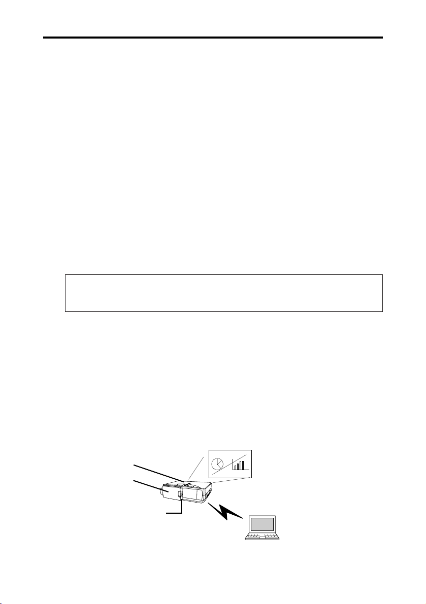
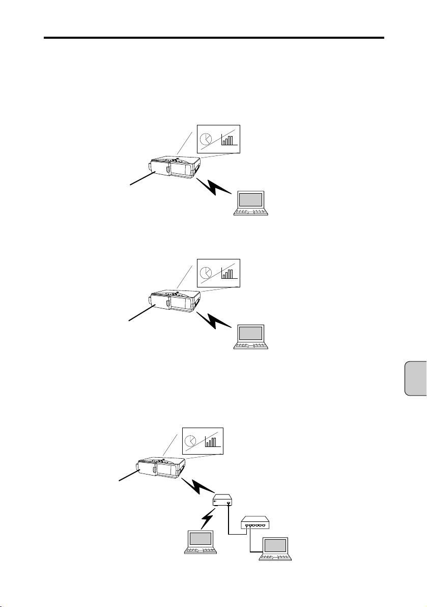
1.2. Image Transfer Flow
Following the image transfer flow, from capturing of the personal computer screen to projection of
images.
1. The screen displayed on the personal computer is captured at real-time with the special software
(WI Client).
2. The captured image data is transferred to Wireless Imager through the wireless LAN (network).
3. Wireless Imager outputs the transferred images to the projector via Digital RGB (DVI) in real-time.
4. The projector will project the screen displayed on the personal computer.
1. Capturing image
2. Data transfer
3. Digital RGB output
4. Projection
Projector
Wireless Imager
Chapter 1.
Page 11

1.3. Operating environment
The following shows the operating environment necessary for Wireless Imager.
Supported OS Microsoft Windows 95/98/ Me
Microsoft Windows NT4.0 workstation
Microsoft Windows 2000 Professional
Microsoft Windows XP Home Edition/Professional
Protocol TCP/IP
Network IEEE802.11b
Recommended personal Pentium III, 600 MHz or higher
computer CPU
Free memory capacity of At least 64 MB or more/128 MB or more recommended
personal computer (128 MB or more recommended for Windows XP)
[NOTE]
More memory capacity may be required depending on application
softwares, which run at the same time.
Free capacity of hard disk drive 10 MB or more
Personal computer display A resolution of VGA (640 x 480), SVGA (800 x 600), or XGA (1024 x
settings 768) or higher is supported.
The number of colors is either 16-bit (65,536 colors) or 24/32-bit
(16,770,000 colors).
Chapter 1. Overview of Wireless Imager
— 11 —
English
Page 12
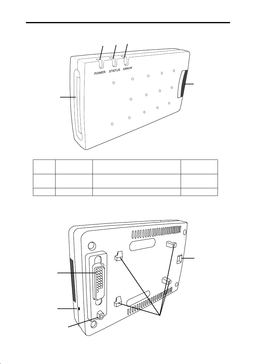
1.4. Part names and functions of Wireless Imager
Status 1. POWER LED 2. STATUS LED 3. ERROR LED
(Green) (Yellow) (Red)
Normal Lit Flashes while packet is being received Off
operation (Only when own node receives the packet.)
Error N/A N/A Lit
4. Wireless LAN card slot: Slot for the wireless LAN card included in the package.
5. Latch button: Used when mounting and removing the unit from the projector.
Chapter 1. Overview of Wireless Imager
— 12 —
1
2
3
4
5
7
6
8
Switch Button
Mounting hooks
These hooks are used to
attach Wireless Imager to a
projector.
Page 13
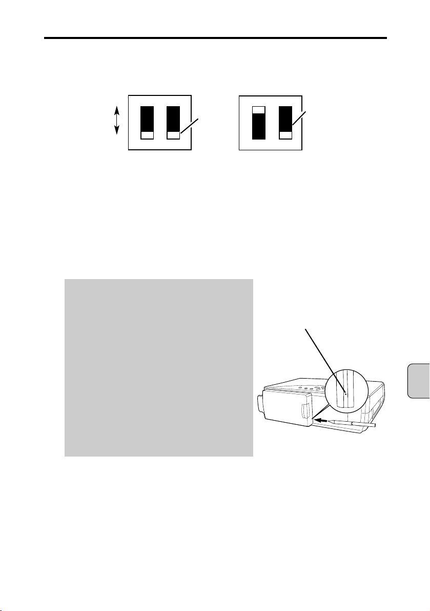
6. Connector plug: Plugs into the projector’s connector.
7. DIP switch: DIP switch 1 toggles between Pseudo Adhoc and 802.11 Adhoc mode.
DIP switch 2 is not used. The factory default mode is 802.11 Adhoc mode.
[NOTE] When the communication mode is set in the infrastructure mode, the DIP switch setting
does not affect the communication (regardless of positions).
8. Test Switch: This switch is used to check various settings for Wireless Imager.
When this TEST switch is pressed at for 1 second while Wireless Imager is operating,
the projector projects Wireless Imager’s settings for approximately 10 sec.
(Press the TEST switch with a sharpened tool.)
(Example Projection contents of factory default settings)
WIRELESS IMAGER INFORMATION:
MAIN PROGRAM: VX.XX(XXXX/XX/XX)
BOOT PROGRAM: VX.XX(XXXX/XX/XX)
HARDWARE: XXXX
CARD TYPE: FCC/IC (1-11) or ETSI (1-13)
MAC ADDRESS: 00C06FXXXXXX
CONFIGURATION #: LAN1
IP ADDRESS: 169.254.100.100
SUBNET MASK: 255.255.0.0
GATEWAY ADDRESS: 255.255.255.255
IP CONFIGURATION: MANUAL
ARP + PING: ENABLE
WIRELESS MODE: 802.11 ADHOC
WIRELESS CHANNEL: 11
WIRELESS SSID/ESSID: WIRELESS
WIRELESS WEP: DISABLE
VGA REFRESH RATE: 59.879 HZ
SVGA REFRESH RATE: 60.317 HZ
XGA REFRESH RATE: 60.004 HZ
[NOTE] Even if the SSID/ESSID is set in lower-case characters, only upper-case characters are
projected. The set values of SSID/ESSID are checked by using the Browser or by viewing
the projector’s menu.
Additionally, it is also possible to reset the settings to the factory default settings by using this
TEST switch. To reset to the factory default settings, refer to [To reset Wireless Imager to the
factory default settings] in the [1.5. Factory default settings].
Chapter 1. Overview of Wireless Imager
— 13 —
English
O F F
12
1
2
O F F
802.11AdHoc
(DIP switch 1 in OFF position)
Pseudo AdHoc
(DIP switch 1 in ON position)
ON
OFF
SWITH
KNOB
Not used
Test Switch
Page 14

Chapter 1. Overview of Wireless Imager
— 14 —
1.5. Factory default settings
The following shows the factory default settings of Wireless Imager.
Item (Expressions of test Factory default settings
projection) *1 LAN 1 *2 LAN 2 *2 LAN 3 *2
Configuration Set
<LAN1> <LAN2> <LAN3>
<CONFIGURATION #>
<IP ADDRESS> <169.254.100.100> <192.168.100.100> *3 <192.168.100.100>
<SUBNET MASK> <255.255.0.0> <255.255.255.0> *3 <255.255.255.0>
<GATEWAY ADDRESS> <255.255.255.255> <255.255.255.255> *3 <255.255.255.255>
IP Configuration method
<MANUAL> <DHCP> <MANUAL>
<IP CONFIGURATION>
<ARP + PING> <ENABLE> <ENABLE> <ENABLE>
<WIRELESS MODE>
Ad-hoc Infrastructure Ad-hoc
<802.11 ADHOC> <INFRASTRUCTURE> <802.11 ADHOC>
Channel
<11> <11> <11>
<WIRELESS CHANNEL>
SSID/ESSID ANY
<WIRELESS SSID/ESSID> <WIRELESS> <ANY (Assigned SSID/ <WIRELESS>
(Uppercase) ESSID will be displayed (Uppercase)
here)>
(Uppercase)
WEP Security
<DISABLE> <DISABLE> <DISABLE>
<WIRELESS WEP>
Admin Password Not set
User Password Not set Not set Not set
Location Not set Not set Not set
*1: Expressions in < > are projected when the TEST switch of Wireless Imager is pressed.
Items without < > are not displayed in the projection using the TEST switch.
*2: Wireless Imager has three preset configuration options. (LAN 1~ LAN 3)
Even if there are several network environments, you can easily change the using environment as
follows. Store the settings of each environment, then select the one suitable for the network
environment you use.
This option is set to LAN 1 as the factory default setting.
To switch this option from one network to another, use web browser or the projector menu.
*3: Set the values of IP address, Subnet Mask and Gateway address of LAN 2 in the table when failing
to obtain from DHCP sever. However, if the addresses has already been changed, then those
values will be set. If you press the test switch do display the settings while Wireless Imager is
attempting to assign an IP address, Subnet Mask, and Gateway Address fields will display [-.-.-.-].
Likewise, if you attempt to display the current settings on the projector’s menu while Wireless
Imager is attempting to assign an IP address, the existing values of IP address, Subnet Mask, and
Gateway Address will be shown. Once the IP address is assigned from DHCP server, the menu
screen will display the obtained IP address.
This applies also when IP Address Setting Method is set to BOOTP.
Page 15

Chapter 1. Overview of Wireless Imager
— 15 —
English
Notes on using Wireless Imager in factory default state
(LAN 1 ~ LAN 3)
When you use your Wireless Imager unit in factory default state, take following precautions.
● [Using LAN1 with Wireless LAN enabled PC]
The PC must have following settings.
IP address: 169.254.0.1 ~ 169.254.255.254
(This is the range of IP addresses for a PC that needs to establish communication with
Wireless Imager. Select “Obtain an IP address automatically” option in TCP/IP
Properties of Windows 98/Me/2000/XP. If there is no DHCP server in the network, an
IP address in this range will be assigned. However, [169.254.100.100] is the default IP
address for Wireless Imager. Therefore, if there is a PC in the network with the same
IP address, you must restart that PC. With regard to duplicate IP address, consult with
your network administrator.)
Wireless mode: 802.11AdHoc
SSID/ESSID: Use the same SSID/ESSID set to your PC
WEP encryption: Disabled (If WEP is set for your PC, configure WEP settings for Wireless
Imager.)
● [Using LAN2 with Wireless LAN enabled PC]
The PC must have following settings.
IP address: “Obtain IP address automatically”
Wireless mode: Infrastructure
SSID/ESSID: Use the same SSID/ESSID set to the access point in the network.
WEP encryption: Disabled (If WEP is set for your access point, configure WEP settings for
Wireless Imager.)
[NOTE] The default SSID/ESSID for Wireless Imager is set to “ANY”. This SSID/ESSID
(“ANY”) allows communication to the access point in the best link condition.
Therefore, if there are several access points in your area, and you want to establish a
link with an access point in the same network segment, you must have Wireless
Imager in the best possible link condition (for example, locate Wireless Imager as
close to the access point as possible).
To check with which access point your Wireless Imager is communicating, press the
Test Switch on the unit to display its current settings. The SSID/ESSID of access
point to which Wireless Imager is communicating will appear in the parenthesis, “( )”,
next to “ANY”. However, the SSID/ESSID that is displayed from the projector will be
in uppercase. For the actual spelling of SSID, consult with you network administrator.
To check the IP address that was obtained from DHCP server, press the Test Switch
on the unit to display current settings. The DHCP-assigned IP address will be shown
in “IP Address”.
Page 16

Chapter 1. Overview of Wireless Imager
— 16 —
● [Using LAN2 with a PC in Ethernet (“wired”) LAN]
The PC must have following settings. The network also must have a DHCP server and a wireless
access point.
IP address: “Obtain IP address automatically”
[NOTE] If WEP is set for your access point, configure WEP settings for Wireless Imager using
Wireless-enabled PC.
To check the IP address that is obtained from DHCP server, press the Test Switch on
the unit to display current settings. The DHCP-assigned IP address will be shown in
“IP Address”.
The default SSID/ESSID for Wireless Imager is set to “ANY”. This SSID/ESSID
(“ANY”) allows communication to the access point in best link condition. Therefore, if
there are several access points in your area, and you want to establish a link with an
access point in the same network segment, you must have Wireless Imager in the
best possible link condition (for example, locate Wireless Imager as close to the
access point as possible).
To check with which access point your Wireless Imager is communicating, press the
Test Switch on the unit to display its current settings. The SSID/ESSID of access
point to which Wireless Imager is communicating will appear in the parenthesis, “( )”,
next to “ANY”.
● [Using LAN3 with wireless LAN enabled PC]
The PC must have following settings.
IP address: 192.168.100.1 ~ 192.168.100.254
( This is the range of IP addresses for a PC that needs to establish communication
with Wireless Imager. However, [192.168.100.100] is the default IP address for
Wireless Imager. Therefore, if there is a PC in the network with the same IP
address, you must assign another IP address to your Wireless Imager. With
regard to duplicate IP address, consult with your network administrator.)
Subnet Mask: 255.255.255.0
Wireless Mode: 802.11AdHoc
SSID / ESSID: Use the same SSID / ESSID to your PC
WEP Encryption: Disabled (If WEP is set for your PC, configure WEP setting for Wireless
Imager.)
● [To reset to the factory default settings]
To reset to the factory default settings, press and hold the TEST switch for approximately 10 seconds.
When all LED are flashing simultaneously, the settings are then returned to the factory default settings.
However, the communication mode is set to “Pseudo AdHoc” or “802.11 AdHoc” by using the DIP switch
on the main unit. ( See the description about [ 7. DIP switch ] of [ 1.4. Part names and functions of main
unit ] in chapter 1. )
Page 17
Chapter 1. Overview of Wireless Imager
— 17 —
English
1.6. Wireless LAN
There are three different types of wireless LAN mode.
[Pseudo AdHoc communication mode]
One-to-one communication of wireless LAN units is performed. (This communication mode uses the
already configured wireless channel.)
[802.11 AdHoc communication mode]
One-to-one communication of wireless LAN units is performed. (This communication mode uses
SSID/ESSID.)
[Infrastructure communication mode]
The wired LAN unit is communicating with the wireless LAN unit through the access point.
Additionally, wireless LAN units are communicating with each other through the access point.
The wireless LAN unit specifies the communication access point using SSID/ESSID.
This communication mode is used for the network environment where wireless LAN units and wired
LAN units are mixed.
Wireless Imager
Wireless mode: Pseudo AdHoc
Personal computer applicable
to wireless communication
Wireless mode: Pseudo AdHoc
Wireless Imager
Wireless mode: 802.11 AdHoc
Personal computer applicable
to wireless communication
Wireless mode: 802.11 AdHoc
Wireless Imager
Wireless mode: Infrastructure
Personal computer applicable
to wireless communication
Wireless mode: Infrastructure
Access Point
Hub
Personal Computer
Page 18
Chapter 2. Connection
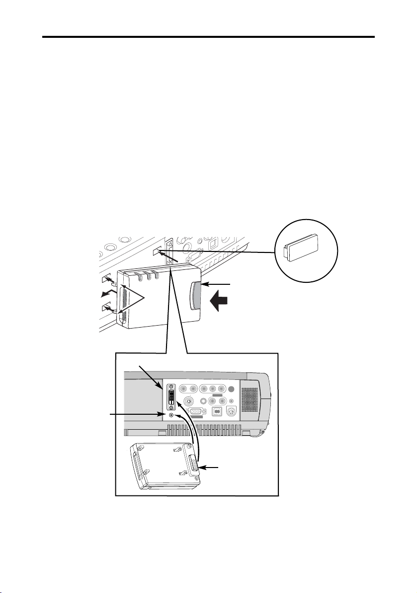
2.1. Mounting Wireless Imager
[CAUTION] Before mounting Wireless Imager, be sure to disconnect the projector’s power plug
from AC outlet. Do not mount Wireless Imager to the projector while its power plug
is connected to AC outlet. It may result in damaging the device.
1. Remove 4 hole covers from the projector. Align and insert Wireless Imager’s mounting hooks (A),
as shown in Figure 1.
2. With pressing Latch Button to the direction of the arrow, insert Wireless Imager’s Connector Plug
into the Projector’s DVI terminal. Press Wireless Imagers gently against the projector to firmly
secure the unit into place. Release your hand when Wireless Imager is properly mounted.
Connection
— 18 —
Latch Button
Figure 1
Hole cover
Remove 4 hole covers
Figure 2
[A]
DVI Terminal
Connector Plug
Align Switch
Button here
Chapter 2.
COMPUTER IN
DVI - I
MCI / WI
R – AUDIO IN – L
S – VIDEO
VIDEO
(MONO)
AUDIO IN
COMPUTER
MONITOR OUT
Y – Pb / Cb – Pr / Cr
AUDIO OUT
R – – L
CONTROL PORT
USB
RESET
Page 19
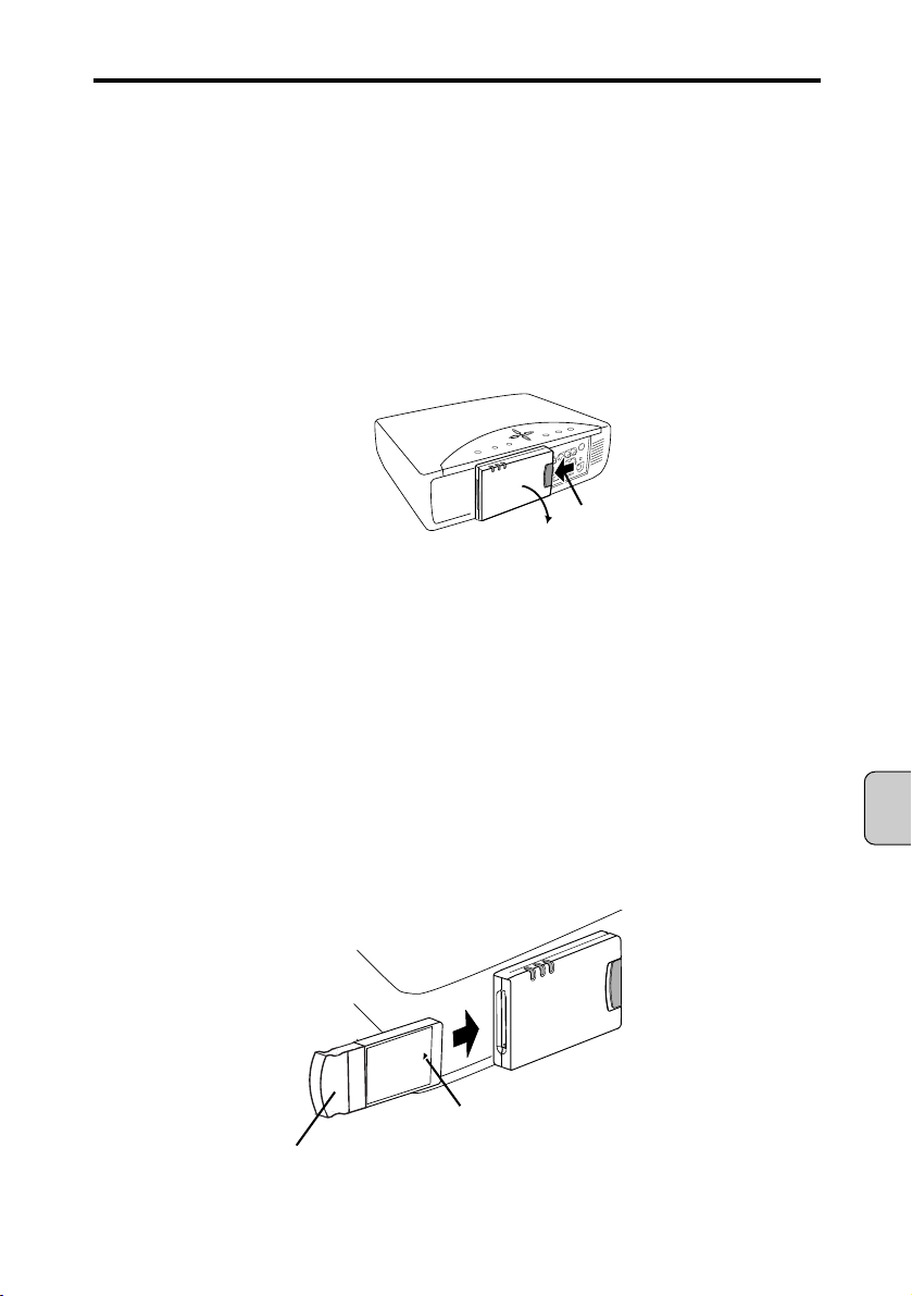
2.2. Removing Wireless Imager
[CAUTION] Before removing Wireless Imager from the projector, be sure to disconnect the
projector’s power plug from AC outlet. Do not remove Wireless Imager to the
projector while its power plug is connected to AC outlet. It may result in damaging
the device.
1. Press the Latch Button to the direction of the arrow (as shown in Figure 3), and gently detach
Wireless Imager from the projector.
[CAUTION] Forcibly detaching the unit off the projector may cause damages.
Figure 3
2.3. Installing Wireless LAN Card
[CAUTION] Before installing the wireless LAN card, be sure to disconnect the projector’s power
plug from AC outlet. Do not install wireless LAN card while projector’s power plug is
connected to AC outlet. It may result in damaging the device.
1. Insert the wireless LAN card into wireless LAN card Slot.
[CAUTION] Be sure to insert the wireless LAN card with the correct side facing up. Inserting the
card with wrong side will result in damaging the device.
Use only the wireless LAN card that is supplied with Wireless Imager. Wireless
Imager does not support any other wireless cards. Attempting to install unsupported
card may damage the unit.
Figure 4
Chapter 2. Connection
— 19 —
English
Press Latch Button to left
and pull back the unit
Insert with ▲ mark facing front
Make sure that the wireless LAN card is
inserted and seated firmly
Wireless LAN card
Page 20
Chapter 3. Software CD-ROM
This chapter describes how to operate the software CD-ROM for Wireless Imager.
This software CD-ROM includes all the softwares necessary to operate Wireless Imager.
[Included software]
•WI Set Software used to configure TCP/IP settings (such as IP address) for Wireless Imager.
•WI Client Software used to transfer the screens from the personal computer to Wireless Imager.
You can also use PJ Controller feature to configure settings in the projector.
[NOTE] The software applications included in this CD-ROM can be used only when you agree to
the contents of “Software license” in the CD-ROM.
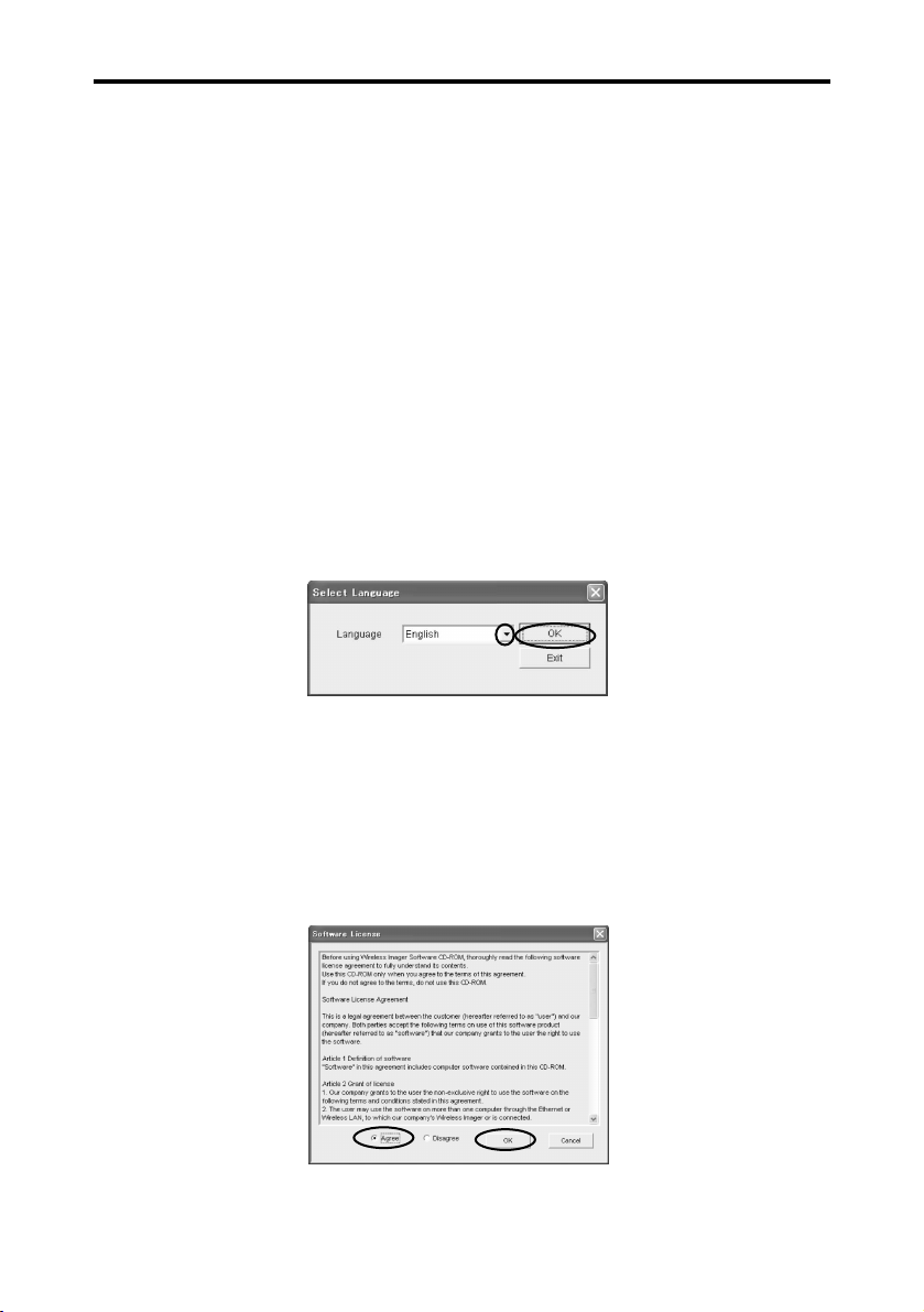
3.1. Starting up the main menu of the software CD-ROM
1. Set the software CD-ROM in the CD-ROM drive of the personal computer.
2. CD-ROM will start automatically and display Language Selection window. Select the language from
the pull-down menu and press OK button.
[NOTE] If the “Language Selection” screen does not appear automatically, open [CD-ROM drive]
of [My Computer] of the personal computer and run “AutoRun.exe”. The “Language
Selection” screen will appear.
3. “Software License” window will be displayed.
Thoroughly read the contents. If you agree to the contents of the software license agreement, check
on the [Agree] radio button and click [OK].
Software CD-ROM
— 20 —
Chapter 3.
Page 21

4. The main menu screen will appear.
From this main menu screen, you may install and run software necessary for Wireless Imager.
3.2. Starting up the IP address setup tool (WI Set)
1. Click the [Launch the IP address setup tool] icon.
The IP address setup tool for Wireless Imager (WI Set) will be started up.
For details about the IP address setup tool (WI Set), see [4.2. Setting the IP address with WI Set ] in
Chapter 4.
[NOTE] WI Set may not be able to detect Wireless Imager, if the firewall feature in some PC virus
detection program is running. When you use WI Set, disable the firewall feature temporarily.
Chapter 3. Software CD-ROM
— 21 —
English
Page 22

Chapter 3. Software CD-ROM
— 22 —
3.3. Installing WI Client
This section describes how to install WI Client.
1. Click the [Install WI Client] icon.
The installer will be started up to start installing WI Client.
2. The installation wizard will be started up. Click [Next].
3. “License Agreement” window will be displayed.
Thoroughly read the contents. If you agree to the contents of the software license agreement, click
[Yes] button.
Page 23

4. The installation destination selection screen will appear. If you accept the default installation folder,
click [Next].
5. The shortcut setup screen will appear. If you do not need to set up the shortcut, check off [Create a
desktop shortcut] and click [Next]. The files are then copied from the CD-ROM.
6. When the files are copied completely, the installation completion screen will appear. Click [Finish].
The installation of WI Client is then completed.
When necessary, read the “Readme” file which appears subsequently.
Chapter 3. Software CD-ROM
— 23 —
English
Page 24

3.4. Starting up WI Client
There are two kinds of WI Client starting up procedures as shown below.
1. Install WI Client from the software CD-ROM to the personal computer.
[NOTE] For details about how to start up the WI Client, see [5.2. Starting up the WI Client] in
Chapter 5.
2. Start up WI Client directly from the software CD-ROM. (See below)
STARTING UP FROM CD-ROM.
[NOTE] WI Set may not be able to detect Wireless Imager, if the firewall feature in some PC virus
detection program is running. When you use WI Set, disable the firewall feature
temporarily.
1. Click the [Launch WI Client] icon. WI Client will be started up.
After the start-up conditions have been displayed on the screen for 3 seconds, the WI Client is
resident in the system tray and relevant icon is shown. When WI Client is started up for the
first time, the screen may vary from the following start-up screen.
[NOTE] For details about how to operate WI Client, see [Chapter 5 Operating WI Client].
Chapter 3. Software CD-ROM
— 24 —
Icon in System Tray
Page 25

English
Setting up Wireless Imager
— 25 —
Chapter 4. Setting up Wireless Imager
This chapter describes how to set up Wireless Imager.
There are two ways to configure Wireless Imager settings.
[A] From a personal computer client
[B] From the projector’s menu
With regard to
[A], there are four steps.
Step 1. Set the communication conditions for the setup personal computer (personal computer
applicable to wireless LAN (applicable to IEEE802.11b)) so that the communication can be
performed with the factory default settings of Wireless Imager.
➜
Refer to [4.1. Setting the personal computer].
Step 2. Using the IP address setup tool for Wireless Imager (WI Set), set IP addresses to Wireless
Imager.
➜
Refer to [4.2. Setting the IP address with WI Set].
Step 3. Using the Web Browser, set the environmental conditions that is actually used on Wireless
Imager.
➜
Refer to [4.3. Setting Up With Browser].
➜
Web Browser to be used must be Microsoft Internet Explorer (Ver. 4.0 or later) or
Netscape Communications Netscape Navigator (Ver. 4.6 or later). This manual describes
with Microsoft Internet Explorer (Ver. 6.0).
Step 4. Return the settings of the setup personal computer to previous settings.
Using the web browser, make sure that your computer can communicate with Wireless
Imager.
With regard to
[B], refer to [4.4. Setting Up Wireless Imager from Projector menu].
4.1. Setting the personal computer
To make the TCP/IP settings for Wireless Imager, it is absolutely necessary to set up the personal
computer.
4.1.1. Setting the personal computer (with wireless LAN card applicable to
“802.11AdHoc” mode)
The personal computer needs the wireless LAN card (adaptor) that allows the wireless LAN
communication (applicable to IEEE.802.11b).
Some wireless LAN cards cannot set the communication mode to “802.11 AdHoc”. In this case, make
the preparations with referring to [4.1.2. Setting the personal computer (with wireless LAN card
applicable only to “Pseudo AdHoc” mode)].
Chapter 4.
Page 26

1. Make sure that the DIP switch on the back panel of Wireless Imager is set in the “802.11AdHoc”
mode. (DIP Switch 1 - OFF : See [1.4. Part names and functions of Wireless Imager] in Chapter 1.)
[CAUTION] Before removing Wireless Imager, be sure to disconnect the projector’s power
plug from AC outlet. Do not remove Wireless Imager to the projector while its
power plug is connected to AC outlet. It may result in damaging the device.
2. Set the wireless communication conditions for the personal computer so that the communication can
be performed with the factory default settings of Wireless Imager.
Set (or change) the following three items.
[Wireless]
1) Communication mode: 802.11 AdHoc (Some manufacturers may use AdHoc or other words.)
2) SSID: WIRELESS (Uppercase)
3) WEP ON/OFF: Disable
[NOTE] For instructions on how to configure wireless settings for the wireless LAN card, refer to
the user’s guide of the wireless LAN card.
After completing the settings, go to [4.2. Setting the IP address with WI Set].
4.1.2. Setting the personal computer (with wireless LAN card applicable to “Pseudo
AdHoc” mode only)
The personal computer needs the wireless LAN card (adaptor) that allows the wireless LAN
communication (applicable to IEEE.802.11b).
Some wireless LAN cards cannot set the communication mode to “Pseudo AdHoc”. In this case, make
the preparations while referring to section [4.1.1. Setting the personal computer (with wireless LAN card
applicable only to “802.11 AdHoc” mode)].
1. Change the DIP switch on the back panel of Wireless Imager to “Pseudo AdHoc” mode (DIP Switch
1 - ON : See [1.4. Part names and functions of Wireless Imager] in Chapter 1.)
[CAUTION] Before removing Wireless Imager, be sure to disconnect the projector’s power
plug from AC outlet. Do not remove Wireless Imager from the projector while its
power plug is connected to AC outlet. It may result in damaging the device.
2. Set the wireless communication conditions for the personal computer so that the communication can
be performed with the factory default settings of Wireless Imager.
Set (or change) the following three items.
[Wireless]
1) Communication mode:
Pseudo AdHoc (Some manufacturers may call it AdHoc or peer-to-peer)
2) Adhoc channel: 11
3) WEP ON/OFF: Disable
[NOTE] For instructions on how to configure wireless settings for the wireless LAN card, refer to
the user’s guide of the wireless LAN card.
After completing the settings, go to [4.2. Setting the IP address with WI Client].
Chapter 4. Setting up Wireless Imager
— 26 —
Page 27

4.2. Setting the IP address with WI Set
To set the IP address of Wireless Imager, you can use WI Set included in the software CD-ROM.
[NOTE] WI Set cannot be used to set Wireless Imager through the router or gateway. Always
use the personal computer in the same segment as that of Wireless Imager. (Only
when the wireless mode is Infrastructure)
1. Check the MAC address (12-digit alphanumeric characters) on the label attached to the back of
Wireless Imager.
[CAUTION] Before removing Wireless Imager, be sure to disconnect the projector’s power
plug from AC outlet.
[NOTE] MAC address is a unique hardware address assigned to each Wireless Imager,
displayed on a label attached to the back of the unit.
2. Mount Wireless Imager to the projector and connect the power cord of the projector to AC
outlet. If the main switch (MAINS SW) is provided to the projector, make the switch ON.
(Not necessary to make the projector projecting.)
3. Insert Software CD-ROM into the personal computer’s CD-ROM drive.
4. CD-ROM will start automatically and display Language Selection window. Select the language
from the pull-down menu and press OK button.
[NOTE] If the “Language Selection” screen does not appear automatically, open [CD-ROM
drive] of [My Computer] of the personal computer and run “AutoRun.exe”. The
“Language Selection” screen will appear.
5. “Software License” window will be displayed.
Thoroughly read the contents. If you agree to the contents of the software license agreement,
check on the [Agree] radio button and click [OK].
Chapter 4. Setting up Wireless Imager
— 27 —
English
Page 28

6. The main menu screen will appear.
7. Click the [Launch the IP address setup tool] icon.
The IP address setup tool (WI Set) will be started up.
8. Click on WI Set pull-down list (▼). The MAC address of Wireless Imager you can set will be
shown in the list. Select the MAC address of Wireless Imager you wish to set the TCP/IP, and
then click the [OK] button.
[NOTE] If the list is not displayed on this screen, the wireless communication conditions for
the personal computer may be set incorrectly. Check the settings again with referring
to [4.1.1. Setting the personal computer (with wireless LAN card applicable to “802.11
AdHoc” mode)] or [4.1.2. Setting the personal computer (with wireless LAN card
applicable to “Pseudo AdHoc” mode only)].
[CAUTION] WI Set may not be able to detect Wireless Imager, if the firewall feature in some
PC virus detection program is running. When you use WI Set, disable the firewall
feature temporarily.
✻ The MAC address on this figure is different from the actual address.
Chapter 4. Setting up Wireless Imager
— 28 —
Page 29

English
Chapter 4. Setting up Wireless Imager
— 29 —
9. Next, the TCP/IP setup screen will appear. Set the following items and click the [Setup] button.
After that, the screen prompting you to confirm the changes will appear. Click [OK] button.
In this manual, TCP / IP is set up as follows:
(This figure is different from the actual settings.)
• Enable DHCP: Disable (Uncheck the check box)
• IP address: 169.254.1.100
• Subnet mask: 255.255.255.0
• Gateway address: 169.254.1.1
[NOTE] Set values in [IP Address] and [Subnet Mask] so that the communication can be
performed with the personal computer you are using. If any segment beyond the
router is not used, the gateway address can be left at “255.255.255.255”. For details
about these settings, consult with your network administrator.
If the admin password is already set, it is required to input the password when clicking
the [Setup] button. For details about admin password, see [4.3.5. Advanced setup -
Admin Password] in Chapter 4.
If you change the settings of Wireless Imager by the browser or WI set while it is
transmitting data in Real-Time Capture mode, the settings prior to the change may be
shown on the display when you view the settings values from the projector’s menu.
At this point, the changed settings are already in effect.
[Disconnect] from Real-Time Capture mode, and view the settings from the
projector’s menu again. Then the new settings will be displayed.
10. Click “Finish” button. When the “TCP/IP Configurations” screen of the IP address setup tool
(WI Set) appears, click [No] to exit WI Set.
Page 30

Chapter 4. Setting up Wireless Imager
— 30 —
4.3. Setting up with the Browser
Using the Web Browser, Wireless Imager is set in the environmental conditions you are actually using.
You can store three separate network settings (LAN 1 ~ LAN 3) in Wireless Imager. (refer to [1.5 Factory
Default Settings] for more details)
To configure Wireless Imager via a web browser, power ON Wireless Imager firstly, and start up the Web
Browser of the personal computer. Input the IP address set of your Wireless Imager to the address field
of the Browser. (For example, http://169.254.1.100.)
Setup screen (next page) appears. Select setup parameter on browser menu.
[NOTE] Web Browser to be used must be Microsoft Internet Explorer (Ver. 4.0 or later) or Netscape
Communications Netscape Navigator (Ver. 4.6 or later). This manual describes using
Microsoft Internet Explorer (Ver. 6.0).
To display the contents of configuration screen in English, select “English” in menu.
If you change the settings of Wireless Imager by the browser or WI Set while it is
transmitting data in Rear-Time Capture mode, the settings prior to the change may be
shown on the display when you view the setting values from the projector’s menu. At this
point, the changed settings are already in effect.
[Disconnect] from Real-Time Capture mode, and view the settings from the projector’s menu
again. Then the new settings will be displayed.
NOTE: Make sure that the Web Browser settings are those shown below.
Proxy server is used When using Internet Explorer
Start up Internet Explorer. Select [Tools] > [Internet Options]. Select the
[Connection] tab and click the [LAN Setup] button in the [Local Area
Network (LAN) Setup] field. Check on [Proxy server is not used at local
address] of the [Proxy Server] field.
Or, make the settings as follows.
Start up Internet Explorer. Select [Tools] > [Internet Options]. Select the
[Connection] tab and click the [LAN Setup] button in the [Local Area
Network (LAN) Setup] field. Click the [Details] button in the [Proxy Server]
field. Input the IP address set on the Wireless Imager in the [Proxy server
is not used at address starting from the following IP address] field.
When using Netscape Navigator
Start up Netscape Navigator. Select [Edit] > [Setup] > [Category]. Select
[Details] and [Proxy], and check on [Set proxy manually.]. Click the
[Display] button and input the IP address set on Wireless Imager in the
[Proxy server is not used at address starting from the following IP address]
field.
Page 31

Proxy server is not When using Internet Explorer
used Start up Internet Explorer. Select [Tools] > [Internet Options]. Select the
[Connection] tab and click the [LAN Setup] button in the [Local Area
Network (LAN) Setup] field. Check off [Proxy server is used at local
address] of the [Proxy Server] field.
When using Netscape Navigator
Start up Netscape Navigator. Select [Edit] > [Setup] > [Category]. Select
[Details] and [Proxy], and check on [Connect Internet directly.].
4.3.1. Information
On the initial screen, the setup contents and current status of Wireless Imager are displayed as
information.
When clicking the [REFRESH] button, the display contents are updated.
Parameter Description
Firmware Version Shows the firmware version of this system.
Boot ROM Version Shows the boot ROM version of this system.
Hardware Address Shows the hardware address (MAC address) of this system.
Wireless Card Type Shows the countries in which the device can be used.
This unit is set to “FCC/IC” or “ETSI” and cannot be changed.
IP Address Shows the IP address currently set on this system. If DHCP is set, the IP
address assigned from the DHCP server is displayed.
Wireless Link Status Shows the wireless communication mode and its status of this system.
WEP Security Shows the WEP (Encryption) setting status.
However, the WEP key is not shown.
Current SSID/ESSID Shows SSID set on this system.
Current Channel Shows the channel, through which this system is currently communicating.
Chapter 4. Setting up Wireless Imager
— 31 —
English
Page 32

Chapter 4. Setting up Wireless Imager
— 32 —
Parameter Description
Data Transfer Rate Shows the current wireless communication speed of this system. The
communication speed is automatically changed by the environment at that
time (11 Mbps, 5.5 Mbps, 2 Mbps, or 1 Mbps). The communication speed
cannot be set at a fixed rate.
Current User /PC Shows the IP address of the personal computer, which is currently
transferring images to this system using WI Client.
System Time Shows the elapsed time since the power is turned on.
The time can be reset by selecting “Reset” from the browser configuration
screen, or by disconnecting power from the projector and connecting back on.
Location Shows an installation location (desired place can be set) set on this system.
Page 33

Chapter 4. Setting up Wireless Imager
— 33 —
4.3.2. Quick setup
On the quick setup screen, minimally required setup items necessary for operation are picked up to allow
easy setup.
[NOTE] The contents of this page is a part of the advanced setup page. Therefore, the contents set
on this page may affect relevant items on the advanced setup. If you set the items on the
advanced setup page, the settings on this page are not necessary.
Parameter Description
Location When using multiple Wireless Imager units, a desired installation place
name can be set to distinguish the Wireless Imager from others. The
installation place name set in this field is displayed with it identified on the
[Connect…] menu of the WI Client.
IP Configuration Method A desired IP address setup method is selected from [Manual], [DHCP],
and [BOOTP].
If [DHCP] or [BOOTP] is selected, the IP address is obtained automatically
as [DHCP client] or [BOOTP client]. At this time, it is absolutely necessary
that the DHCP server/BOOTP server must be in the environment allowing
the network communication.
[NOTE]
When the IP Address Configuration Method is set to DHCP or BOOTP, and you
press the test switch to display the settings while Wireless Imager is attempting to
obtain an IP address, IP Address, Subnet Mask, and Gateway Address fields will
display [-.-.-.-].
Likewise, if you attempt to display the current settings on the projector’s menu
while Wireless Imager is attempting to obtain an IP address, the existing values of
IP address, Subnet Mask, and Gateway Address will be shown. Once the IP
address is obtained from DHCP server, the menu screen will display the obtained
IP address.
If Wireless Imager fails to obtain IP address from DHCP server or BOOTP server,
the existing IP address will be assigned.
IP Address Set the IP address in the environment you wish to use.
If [IP Configuration Method] is set at [DHCP] or [BOOTP], this setting is
not needed.
Subnet Mask Set the Subnet mask in the environment you wish to use.
If [IP Configuration Method] is set at [DHCP] or [BOOTP], this setting may
become unnecessary depending on the settings of [DHCP Server] and
[BOOTP Server].
English
Page 34

Chapter 4. Setting up Wireless Imager
— 34 —
Parameter Description
Gateway Address Set the gateway address in the environment you wish to use.
If [IP Configuration Method] is set at [DHCP] or [BOOTP], this setting may
become unnecessary depending on the settings of [DHCP Server] and
[BOOTP Server].
If any segment beyond the router is not used, the gateway address can be
left at “255.255.255.255”.
Wireless Mode Set the wireless communication mode in the environment you wish to use.
Select either “Infrastructure” or “AdHoc”.
Channel Set the channel when the system is used in the “Pseudo AdHoc” mode.
Select from available channels in each region; North America (USA and
Canada): 1 ~11; Europe: 1~13; France: 10~13.
SSID/ESSID Set SSID/ESSID when the system is used in the “Infrastructure” or
“802.11 AdHoc” mode.
[NOTE] If a SSID/ESSID, other than “ANY”, is to be used in Infrastructure
mode, the same SSID/ESSID must be set to Wireless Imager,
access point, and the wireless-enabled client PC.
In 802.11 Adhoc mode, the same SSID must be set to Wireless
Imager and the wireless-enabled client PC.
SSID/ESSID is case-sensitive. Even though all characters
projected by pressing the TEST switch on Wireless Imager are
uppercase, it is necessary to distinguish between upper and
lower case characters.
If the contents you have set on this page are correct, click the [APPLY] button.
The screen prompting you to restart Wireless Imager will appear. If no other configuration change is
necessary, click the [RESTART] button to restart Wireless Imager. The changed settings will take effect
upon Restart.
[NOTE] WEP (Encryption) cannot be set on the Quick Setup screen. When using WEP, click the
[BACK] button before restarting and make the settings on the screen described in [4.3.4.
Advanced setup-Wireless].
To return the contents you have set to the previous settings, click the [REFRESH] button
before pressing [APPLY] button.
To return the settings to the factory default settings, click the [Restore Factory Default
Settings] button. Only quick setup items are then returned to the factory default settings.
Page 35

Chapter 4. Setting up Wireless Imager
— 35 —
English
4.3.3. Advanced setup - TCP/IP
On the TCP/IP setup screen of the advanced setup, TCP/IP related items of Wireless Imager can be set.
Parameter Description
IP Configuration Method A desired IP address setup method is selected from [Manual], [DHCP],
and [BOOTP].
If [DHCP] or [BOOTP] is selected, the IP address is assigned
automatically as [DHCP client] or [BOOTP client]. At this time, it is
absolutely necessary that the DHCP server/BOOTP server must be in the
environment allowing the network communication.
[NOTE]
When the IP Address Configuration Method is set to DHCP or BOOTP, and you
press the test switch to display the settings while Wireless Imager is attempting to
obtain an IP address, IP Address, Subnet Mask, and Gateway Address fields will
display [-.-.-.-].
Likewise, if you attempt to display the current settings on the projector’s menu
while Wireless Imager is attempting to obtain an IP address, the existing values of
IP address, Subnet Mask, and Gateway Address will be shown. Once the IP
address is obtained from DHCP server, the menu screen will display the obtained
IP address.
If Wireless Imager fails to obtain IP address from DHCP server or BOOTP server,
the existing IP address will be assigned.
IP Address Set the IP address in the environment you wish to use.
If [IP Configuration Method] is set at [DHCP] or [BOOTP], this setting is
not needed.
Subnet Mask Set the Subnet mask in the environment you wish to use.
If [IP Configuration Method] is set at [DHCP] or [BOOTP], this setting may
become unnecessary depending on the settings of [DHCP Server] and
[BOOTP Server].
Gateway Address Set the gateway address in the environment you wish to use.
If [IP Configuration Method] is set at [DHCP] or [BOOTP], this setting may
become unnecessary depending on the settings of [DHCP Server] and
[BOOTP Server].
If any segment beyond the router is not used, the gateway address can be
left at “255.255.255.255”.
Page 36

Chapter 4. Setting up Wireless Imager
— 36 —
Parameter Description
ARP+PING Whether the IP address setup with “arp” and “ping” commands is made
enabled or disabled is selected.
Normally, the default setting “Enable” can be used.
For details about how to set the IP address with ARP+PING, see [6.2.
Setting the IP address with “arp + ping” command] in Chapter 6.
If the contents you have set on this page are correct, click the [APPLY] button.
The screen prompting you to restart Wireless Imager will appear. If no other configuration change is
necessary, click the [RESTART] button to restart Wireless Imager. The changed settings will take effect
upon Restart.
[NOTE] To return the contents you have set to the previous settings, click the [REFRESH] button
before pressing [APPLY] button.
To return the settings to the factory default settings, click the [Restore Factory Default
Settings] button. Only TCP/IP setup items are then returned to the factory default
settings.
Page 37

Chapter 4. Setting up Wireless Imager
— 37 —
English
4.3.4. Advanced setup – Wireless
On the wireless setup screen of the advanced setup, wireless related items of Wireless Imager can be set.
Parameter Description
Wireless Mode Set the wireless communication mode in the environment you wish to use.
Select either “Infrastructure” or “AdHoc”.
“AdHoc” provides “Pseudo AdHoc” and “802.11 AdHoc”. Using the DIP
switch on Wireless Imager unit, set a desired AdHoc mode. (For details,
see [1.4. Part names and functions of main unit] in Chapter 1.)
To check which mode is currently set, press the TEST switch on Wireless
Imager. (For details, see [1.4. Part names and functions of main unit] in
Chapter 1.)
Channel Set the channel when the system is used in the “Pseudo AdHoc” mode.
Select from available channels in each region; North America (USA and
Canada): 1 ~11; Europe: 1~13; France: 10~13.
SSID/ESSID Set SSID/ESSID when the system is used in the “Infrastructure” or
“802.11 AdHoc” mode.
[NOTE] If a SSID/ESSID, other than “ANY”, is to be used in Infrastructure
mode, the same SSID must be set to Wireless Imager, access
point, and the wireless-enabled client PC.
In 802.11 Adhoc mode, the same SSID must be set to Wireless
Imager and the wireless-enabled client PC.
SSID/ESSID is case-sensitive. Even though all characters
projected by pressing the TEST switch on Wireless Imager are
uppercase, it is necessary to discriminate between upper and
lower case characters.
WEP Security Set whether or not WEP (Encryption) is used.
When using WEP, select any of [Enable (40bit/Shared Key)], [Enable
(40bit/Open System)], [Enable (128bit/Shared Key)], and [Enable
(128bit/Open System)] corresponding to this WEP.
[NOTE] When using WEP (Encryption), the image transfer speed may
become slow.
WEP key 1 to key 4 Set WEP key in the hexadecimal notation (0 to F). 5 bytes are set for 40-
bit WEP and 13 bytes are set for 128-bit WEP.
Page 38

If the contents you have set on this page are correct, click the [APPLY] button.
The screen prompting you to restart Wireless Imager will appear. If no other configuration change is
necessary, click the [RESTART] button to restart Wireless Imager. The changed settings will take effect
upon Restart.
[NOTE] To return the contents you have set to the previous settings, click the [REFRESH] button
before pressing [APPLY] button.
To return the settings to the factory default settings, click the [Restore Factory Default
Settings] button. Only Wireless setup items are then returned to the factory default
settings.
[NOTE] No advanced setup items are provided depending on PCs and access points. If there is
only Enable/Disable setting of WEP, set Wireless Imager as [Enable (40 bit/ open
system)] firstly. If communication cannot be conducted properly, select [Enable (40 bit/
shared key)].
If you can set Enable/Disable and the bit number, set Wireless Imager as [Enable (40 bit/
open system)] or [Enable (128 bit/ open system)] in accordance with the bit number. If it
cannot communicate properly, select [Enable (40bit/ shared key)] or [Enable (128bit/
shared key)] in accordance with the bit number.
If the setting of WEP encryption does not fit to a PC and an access point, Wireless
Imager cannot communicate properly. Return to Factory Default Setting and reset
Wireless Imager.
Four WEP keys can be set, however, the only one with check on the radio button is in
effect. Both of the number and the value of WEP key in effect must be same as the
setting of a PC and an access point.
Depending on PCs and access points, you may be allowed to select only one WEP key.
In this case, use WEP key 1.
Chapter 4. Setting up Wireless Imager
— 38 —
Page 39

4.3.5. Advanced setup – Admin Password
On Admin Password setup screen of the advanced setup, an admin password can be set so that
personnel other than the system administrator cannot change the set contents of Wireless Imager. With
the factory default settings, this password is not set.
[NOTE] Always record the password you have set. If you forget the password, you must initialize
all settings of Wireless Imager. (See [1.5. Factory default Settings].)
After setting an admin password, you will be prompted to enter the password whenever
you change the device settings via the web browser or WI Set. You will not need the
password when the settings are changed from the projector menu.
Parameter Description
Enter Current Admin Password Input the currently set admin password. The password you have
input is shown like “●●●●●●●”.
Enter New Admin Password Input a new admin password you wish to set. The password you
have input is shown like “●●●●●●●”.
Re-enter New Admin Password Re-enter the new admin password you wish to set. The password
you have input is shown like “●●●●●●●”.
[NOTE] If you set the admin password for the first time, you do not input any password in the
[Enter Current Admin Password] field. Enter a desired password in [Enter New Admin
Password] and [Re-enter New Admin Password] fields.
You can assign respective user password for three different LAN environments (LAN 1 to
LAN 3), but the same Admin password will be used for all three LAN settings.
Chapter 4. Setting up Wireless Imager
— 39 —
English
Page 40

If the contents you have set on this page are correct, click the [APPLY] button.
The screen showing that the password has been updated will appear. Click the [BACK] button.
When changing the set contents next time, the password entry request screen will appear. Keep the
[User Name] field blank and input the password to the [Password] field.
Chapter 4. Setting up Wireless Imager
— 40 —
Leave User name
field blank
Page 41

Chapter 4. Setting up Wireless Imager
— 41 —
English
4.3.6. Advanced setup – User Password
On the user password setup screen of the advanced setup, the user password can be set, which is used
when using WI Client.
[NOTE] By setting a user password, you can restrict access to the Wireless Imager.
The user will be prompted to enter a password, when accessing Wireless Imager via WI
Client.
When setting the user password, always record the user password you have set.
It is possible to set the user password different from the Admin Password.
You can assign respective user password for LAN 1, LAN 2, and LAN 3 configuration set.
Parameter Description
Enter New User Password Input a new password you wish to set. The password you have
input is shown like “●●●●●●●”.
Re-enter New User Password Re-enter the new password you wish to set. The password you
have input is shown like “●●●●●●●”.
[NOTE] When setting the user password again, the current user password is not necessary.
Changing of the user password is protected by the administrator password. When setting
the user password, it is recommended to set the administrator password.
If the contents you have set on this page are correct, click the [APPLY] button.
The screen showing that the password has been updated will appear. Click the [BACK] button.
Page 42

4.3.7. Advanced setup - Miscellaneous
On Miscellaneous setup screen of the advanced setup, desired location names are set to distinguish
Wireless Imager when using multiple Wireless Imager units.
Parameter Description
Location Set each location name. Location names set in this field are respectively displayed
on the connect menu of WI Client.
If the contents you have set on this page are correct, click the [APPLY] button.
The screen prompting you to restart Wireless Imager will appear. If no other configuration change is
necessary, click the [RESTART] button to restart Wireless Imager. The changed settings will take effect
upon Restart.
[NOTE] To return the contents you have set to the previous settings, click the [REFRESH] button
before pressing [APPLY] button.
To return the settings to the factory default settings, click the [Restore Factory Default
Settings] button. Only Miscellaneous items are then returned to the factory default
settings.
Chapter 4. Setting up Wireless Imager
— 42 —
Page 43

4.3.8. Change Configuration Set
On Change Configuration Set screen, you can select a set of desired LAN settings to be activated from
LAN 1, LAN 2, or LAN 3.
You can also check following parameter settings under each LAN settings.
● Location
● IP Configuration Method
● IP Address
● Wireless Mode
● Channel
● SSID/ESSID
● WEP Security
Check on the check box of Configuration Set (LAN 1 ~ LAN 3) you wish to activate.
If the contents you have set on this page are correct, click the [APPLY] button.
The screen prompting you to restart Wireless Imager will appear. If no other configuration change is
necessary, click the [RESTART] button to restart Wireless Imager. The changed settings will take effect
upon Restart.
[NOTE] To return the contents you have set to the previous settings, click the [REFRESH] button
before pressing [APPLY] button.
To change the setting in each Configuration Set (LAN 1 ~ LAN 3), select the desired
Configuration Set in this screen and click [APPLY]. Then, click [Back] button on the
browser menu and change the settings.
Chapter 4. Setting up Wireless Imager
— 43 —
English
Page 44

4.3.9. Restart
On the restart screen, Wireless Imager can be restarted. Click the [RESTART] button.
When you changed settings in other page (TCP/IP, Wireless, etc.) but not yet restarted Wireless Imager
unit, you can click [Restart] button to activate the new settings.
When you access Wireless Imager after changing the setting;
Enter the new IP address in the address field of the Browser to access Wireless Imager. You are not
allowed to access with the previous IP address.
Chapter 4. Setting up Wireless Imager
— 44 —
Page 45

4.4. Setting up Wireless Imager from Projector menu
This section describes how to configure network settings for Wireless Imager from the projector’s menu.
You can configure Wireless Imager settings with the projector’s remote control unit or control panel.
You can store three separate network settings (LAN 1 ~ LAN 3) in Wireless Imager.
If you are using Wireless Imager in multiple network environments, you can easily change from one
network setting to another by creating and saving the settings suitable for each network. See [1.5
Factory Default Settings] in Chapter 1 for more details.
1. Power on the projector to display the menu on the screen.
Press MENU button, and select SETTING MENU > Wireless Imager, and press SELECT button.
2. Using the pointer [ / ], select the target network to be configured from LAN 1, LAN 2, or
LAN 3.
In the following example, we will select LAN 1.
[NOTE] If you have already configured network settings for LAN 1, LAN 2 and/or LAN 3, and
just want to switch from one LAN setting to another, select the target LAN using the
pointer [ / ] and press [SELECT] button. Then the network configuration screen
appears. Press MENU button to close this screen. The selected Configuration set
will be activated.
Chapter 4. Setting up Wireless Imager
— 45 —
English
Setting menu
Wireless Imager
LAN Selection
▼
▼
▼
▼
Page 46

3. Press SELECT button to display the network configuration screen.
Using the pointer [ /▲/▼/ ], move to each field and change settings.
Use / to move to different fields.
Use ▲ / ▼ to change the value in each field.
Parameter Description
IP Address Set the IP address in the environment you wish to use.
Sub net Set the Subnet mask in the environment you wish to use.
Gateway Set the gateway address in the environment you wish to use.
If any segment beyond the router is not used, the gateway address can be
left at “255.255.255.255”.
Current Channel Set the channel when the system is used in the “Pseudo AdHoc” mode.
Select from available channels in each region; North America (USA and
Canada): 1 ~11; Europe: 1~13; France: 10~13.
Connection Status Set the wireless communication mode in the environment you wish to use.
Select either “Infrastructure” or “AdHoc”.
“AdHoc” provides “Pseudo AdHoc” and “802.11 AdHoc”. A desired AdHoc
mode is set using the DIP switch on Wireless Imager unit. (For details, see
[1.4. Part names and functions of main unit] in Chapter 1.)
Additionally, pressing the TEST switch on Wireless Imager can check
what mode is currently set. (For details, see [1.4. Part names and
functions of main unit] in Chapter 1.)
SSID/ESSID/IBSSID Set SSID/ESSID when the system is used in the “Infrastructure” or
“802.11 AdHoc” mode.
[NOTE] If a SSID/ESSID, other than “ANY”, is to be used in Infrastructure
mode, the same SSID must be set to Wireless Imager, access
point, and the wireless-enabled client PC.
In 802.11 Adhoc mode, the same SSID must be set to Wireless
Imager and the wireless-enabled client PC.
SSID/ESSID is case-sensitive. Even though all characters
projected by pressing the TEST switch on Wireless Imager are
uppercase, it is necessary to discriminate between upper and
lower case characters.
Chapter 4. Setting up Wireless Imager
— 46 —
▼
▼
▼
▼
Page 47

4. When the configuration is completed, press SELECT button, and the changed settings will be active.
[NOTE] If you close the menu by MENU button before pressing [SELECT], the changed
settings cannot be activated.
If you set the configuration of LAN1 ~ LAN3, the last configured LAN setting will be
activated. For example, if you configured LAN1 settings last, Wireless Imager starts
up with LAN1 settings.
You cannot set WEP encryption for wireless configuration from the projector menu. If
WEP setting is required, use web browser configuration method (refer to [4.3. Setting
up with the Browser] in chapter 4).
If you set SSID/ESSID by a PC, do not put blank space following letters. Wireless
Imager regards blank space as “no character”, which may result in communication
error.
Chapter 4. Setting up Wireless Imager
— 47 —
English
Page 48

Chapter 5. Operating the WI Client
This chapter describes how to operate WI Client used to transfer images of the personal computer.
By accessing to Wireless Imager with WI Client application software, you can transmit the image from
your PC screen to a projector, and also remotely operate and configure the projector.
[NOTE] Only one PC can transmit the images to Wireless Imager at a time. Multiple PCs cannot
transmit simultaneously.
This system is not applicable to an application software using DirectX, MS-Office assistant,
and replaying of motion pictures, such as DVD.
5.1. Preparing the client personal computer
Prepare a personal computer used to operate Wireless Imager. Check the following items about the
personal computer.
• Check the hardware specifications of the personal computer. (For details, see [1.3. Operating
environment] in Chapter 1.) If the hardware specifications of the personal computer are
insufficient, Wireless Imager may not be operated at its maximum operating level.
• It is necessary to install a wireless LAN card (adaptor) allowing wireless LAN communication
(applicable to IEEE802.11b) in the personal computer.
However, when using the infrastructure communication (communication through access points),
the communication can also be performed from the wired LAN (Ethernet) side. In this case, the
personal communication needs only the wired LAN (Ethernet) card.
Make sure that the communication can be performed with the contents set in Chapters 4.
• Make sure that the WI Client is installed in the personal computer you wish to use. (For details,
see [3.3. Installing WI Client] in Chapter 3.)
[NOTE] It is not absolutely necessary to install WI Client. You can also run WI Client directly
from the software CD-ROM. (For details, see [3.4. Starting up WI Client] in Chapter 3.)
Operating the WI Client
— 48 —
Chapter 5.
Page 49

5.2. Starting up WI Client
1. Turn the projector power on and select WI input (Wireless Imager).
2. From the [Start] menu of Windows, select [Program] > [Wireless Imager] > [WI Client] in that order.
WI Client is then started up. When WI Client is started up for the first time, the “Connect to WI Host”
screen will appear.
If the Wireless Imager you wish to connect is not displayed in “Target List”, click the [Search] button.
When the Wireless Imager you wish to connect is displayed, select it from “Target List”, and then
click the [Connect] button.
When clicking the [Connect] button, WI Client is resident in the system tray and relevant icon is
shown. After that, you can run the WI Client.
[NOTE] WI Set may not be able to detect Wireless Imager, if the firewall feature in some PC virus
detection program is running. When you use WI Set, disable the firewall feature temporarily.
[NOTE] When WI Client is started up for the second or subsequent time, the “Connect to WI Host”
screen does not appear. Instead, the start-up conditions are displayed on the screen for
3 seconds, and then WI Client is resident in the system tray and relevant icon is shown.
If you wish to display “Connect to WI Host” window, click “Connect to WI Host” from the
menu (refer to [5.3. WI Client Menu]).
Chapter 5. Operating the WI Client
— 49 —
English
Icon in System Tray
Page 50

[NOTE] If the user password is set as described in [4.3.6. Advanced setup - User password] in
Chapter 4, it is necessary to input the password in the [Password] field on the “Connect to
WI Host“ screen. If incorrect user password is input or password is not input, the user
password entry screen remains. Input the correct user password. (The input user
password is shown like “******”)
5.3. WI Client Menu
When right-clicking the icon in the system tray, the menu of the WI Client will be shown.
1. Real Time Capture
When [Real Time Capture] is selected, the personal computer is then connected to Wireless
Imager marked in the “Connect to WI Host” dialog box at any time.
In the real time capture, every time the screen displayed on the personal computer is changed, the
changed screen is captured, and then transferred to Wireless Imager.
The icon in the system tray is changed to the connecting icon while the screen data is being
transferred at real-time.
[NOTE] If you are using WI Client with Windows XP, and the password protection is enabled for
the screen saver, the Real-Time Capture stops, as soon as the screen saver starts.
However, when you log back on with your password and out of screen saver mode, the
Real-Time Capture mode will start again.
Disable the password protection if necessary.
Chapter 5. Operating the WI Client
— 50 —
Right-clicking the icon in
the system tray
Disconnected Connected
▼
Page 51

2. One-Shot Capture
When selecting [One-shot Capture], the personal computer is then connected to Wireless Imager
marked in the “Connect to WI Host” dialog box temporarily.
In One-shot Capture mode, only the screen displayed on the personal computer at that time is
captured, and then transferred to Wireless Imager. After the screen images have been transferred,
the connection to Wireless Imager is disconnected. However, the projector continues to project the
screen transferred in the One-Shot Capture mode.
The icon in the system tray is changed to the connecting icon during one-shot capture, and then
changed to the disconnecting icon.
[NOTE] When “Real Time Capture” and “One-Shot Capture” cannot be conducted successfully,
exit WI Client by selecting [Quit] and restart the WI Client.
3. Disconnect
To abort the image transfer in the Real Time Capture mode, select [Disconnect] in the menu.
[NOTE] When Disconnect is selected from the menu, the projector will keep displaying the image
just before disconnecting.
4. Connect
When clicking [Connect…], the “Connect to Wireless Imager Host” screen will appear.
If Wireless Imager you wish to connect is not displayed in “Target List”, click the [Search] button.
When the Wireless Imager you wish to connect is displayed, select it from “Target List”, select a
desired connection method, [Real Time Capture] or [One-shot Capture], and then click the [Connect]
button.
[NOTE] It is not possible to select and connect to multiple Wireless Imager.
The personal computer is then connected to the Wireless Imager under selected conditions to
transfer the screen.
Chapter 5. Operating the WI Client
— 51 —
English
Disconnected Connected Disconnected
▼
Page 52

[NOTE] If the user password is set as described in [4.3.6. Advanced setup - User password] in
Chapter 4, it is necessary to input the password in the [Password] field on the “Connect to
Wireless Imager Host“ screen. If incorrect user password is input or password is not
input, the user password entry screen remains. Input the correct user password (The
input user password is shown like “******”.).
5. Options
When selecting [Options….], you may set up the options of the image to be transferred
corresponding to its purpose.
[NOTE] (With Windows XP only) Compared to setting PC’s display setting to 16 bit, the transfer rate
may slow down, if the Options are set to following,
(Options setting in WI Client)
Image Type: Presentation
Display Color: 16 bit
(Display setting for PC)
Colors: 24 bit or 32 bit
In this case, change the color setting for the PC monitor to 16 bit.
(A) Select a desired image type, Presentation mode or Photo mode.
● Presentation mode
You may select [Presentation Mode] if you wish to display characters and/or graphs, etc. When
selecting [Presentation Mode], the display color is selected from either [16 bit] or [24 bit].
● Photo mode
You may select [Photo Mode] if you wish to display natural pictures, such as photos displayed
on the personal computer. When selecting [Photo Mode], the display color is fixed at [24 bit]
and [16 bit] cannot be selected.
Chapter 5. Operating the WI Client
— 52 —
Page 53

(B) Select a desired display color setting, [16 bit] or [24 bit].
● 16 bit
When checking on [16 bit], the colors are transferred at a maximum rate of 16 bits. The
transfer speed becomes faster, compared to 24-bit transfer
● 24 bit
When checking on [24 bit], the colors are transferred at a maximum rate of 24 bits. When the
image type is set at [Photo Mode], the display color is fixed at 24 bits.
[NOTE] The display color of the options setup of WI Client may depend on the display
setting of the personal computer.
Display setting of Display color setting of options Display color projected
personal computer (bit) setup of WI Client (bit) by projector (bit)
16
16 16
24 16
24
16 16
24 24
32 (*1)
16 16
24 24
*1: Even though the display setting of the personal computer is set at [32 bit], the number of
colors becomes 16,770,000 colors, the same as 24 bit.
6. Set to Default
When clicking [Set to Default], the current settings (Options, Target, transfer mode (real-time capture
or disconnect)) are saved. When running WI Client next time, it is possible to run it with the same set
values.
For example, if you click [Set to Default] to exit WI Client when your PC is connected to certain
Wireless Imager with the settings : real-time capture, presentation mode and 16 bit, your PC will
connect to the same Wireless Imager with the same image settigs and real-time capture when
restarting WI Client.
7. About WI Client
When clicking [About WI Client], the version information about WI Client will be shown.
8. Help
When clicking [Help], the help about WI Client will be shown.
Chapter 5. Operating the WI Client
— 53 —
English
Page 54

9. PJ Controller
When selecting [PJ Controller...], you can launch PJ Controller to operate and configure the projector
from your PC. (Refer to 5.4. PJ Controller, for more details)
[NOTE] You cannot launch [PJ Controller...] while the PC is connected to Wireless Imager in either
Real-Time mode or in One-Shot mode. Make sure that WI Client is in [Disconnect] state.
If there are multiple Wireless Imager units in the area, make sure in [Connect to Wireless
Imager Host] screen that you are connecting to the correct target. You are not allowed to
connect PJ controller to multiple Wireless Imager Units.
10. Quit
When selecting [Quit] during real-time capture, the communication is disconnected and WI Client is
then exited. (Refer to [5.5. Exiting WI Client] for more details)
Chapter 5. Operating the WI Client
— 54 —
Page 55

5.4. PJ Controller
With PJ Controller, you can operate and configure the projector to which Wireless Imager is installed.
1. Right-click the icon in the system tray, and make sure that WI Client is in [Disconnected] state.
Verify also that the correct target is selected.
[NOTE] You cannot launch [PJ Controller...] while the PC is connected to Wireless Imager in either
Real-Time mode or in One-Shot mode. Make sure that WI Client is in [Disconnect] state.
2. Select [PJ Controller...] from the menu and launch PJ Controller.
Next, select [Initial Setting] from Main Menu, and configure appropriate fields.
Make sure that you select correct [Model Name].
Parameter Description
Language Select a desired language from the pull-down menu, and click [Set] button.
Model Name Select a model name of the projector to which Wireless Imager is installed.
Model Name is listed as code in OPTIONAL PARTS section of the projector’s
owner’s manual.
[NOTE] If you do not select correct model name, you will not be able to operate
or configure the projector using PJ Controller.
Comment You can store any comments regarding the initial settings. To save the
comments you entered, click [Save] button.
Chapter 5. Operating the WI Client
— 55 —
English
Right-click the icon in
the system tray
About Model Name:
Model Name is the actual model name of the
projector you wish to control with PJ Controller.
Model Name is shown as code in OPTIONAL
PARTS section in your projector’s owner’s
manual. Check your projector’s model name
carefully and select the correct Model Name
code from pull-down list. In order to control
your projector properly, you must select the
correct Model Name Code.
Page 56

3. After the initial settings are completed, select other menu items in Main Menu to operate or configure
the projector.
Refer to [5.4.1. Power and Status] ~ [5.4.3. Display Menu] for more detailed descriptions of each
menu item.
[NOTE] The menu items may vary depending on the projector type.
4. When you finish controlling or configuration using PJ Controller, select [Exit] from [File] menu and exit
PJ Controller application.
[NOTE] You cannot connect to Wireless Imager in either Real-Time mode or in One-Shot mode
while PJ Controller is running.
5.4.1. Power & Status
In Power & Status screen, you can configure
and control projector’s power.
Parameter Description
Projector Power You can control projector’s power by clicking either [Standby] or [ON]
button.
[NOTE] You cannot turn on the projector for approximately 90
seconds after shutting down the power. If the projector’s
LED is indicating [Cooling] status, you cannot turn on the
projector. Wait until the indicator light turns from [On cooling
down] to [Standby], then click [ON] button to turn on the
power.
Accumulated Lamp-use time Accumulated time of lamp use is displayed in an hour increment.
This counter is reset when the lamp is replaced and by resetting the
Lamp replacement counter.
Accumulated Projector-use Accumulated projector use time is displayed in an hour increment.
time
Power Status The status of projector’s lamp is displayed in following status:
ON, Standby, Lamp Off/Standby, OFF, On cooling down, Lamp
Off/On cooling down, Power Saver Mode/On cooling down,
Temperature Error/On cooling down, On starting up, On power
management operating, Temperature Error/Standby
Projector Condition The projector’s condition is displayed in following status:
Normal, Temperature Error, Power Failure, Lamp Off, Standby
Input Status Selected mode and the signal status are displayed.
[NOTE] Since configuration parameters vary depending on the projector model, the contents
mentioned above may be different from the actual configuration. For details, refer to
Owner’s Manual of each projector.
Chapter 5. Operating the WI Client
— 56 —
Page 57

5.4.2. Control
Various control menus are displayed in Control window.
When you select an icon, the corresponding configuration window will appear, and you can set up your
projector.
[NOTE] The control page automatically shows the necessary configuration parameters depending
on the selected input mode.
Therefore, the contents of screen display may differ slightly from the description.
Furthermore, depending on the Input source, some items may not be configurable. Refer to
the projector’s owner’s manual for more details on how to configure each item.
When the projector is in Standby mode, the configuration changes on the Control menu will
not take effect.
Input
You can select Input terminal and Input source.
Parameter Description
Input You can select which input terminal to use by checking on an appropriate
radio button.
If the pull-down menu is displayed, you can select an Input source.
[NOTE] Input terminal [WI] is the digital RGB terminal to which Wireless
Imager is connected.
Comment You can store any comments regarding the initial settings. To save the
comments you entered, click [Save] button.
[NOTE] Since configuration parameters vary depending on the projector model, the contents
mentioned above may be different from the actual configuration. For details, refer to
Owner’s Manual of each projector.
Chapter 5. Operating the WI Client
— 57 —
English
Page 58

PC Adjustment
This feature optimizes the signal from a connected PC for better quality projection.
[NOTE] [PC] control screen is only displayed when analog computer is selected as the
input source.
Parameter Description
Auto PC Adjustment Click [Start] button to initiate Auto PC Adjustment.
Fine Synch Use / button to adjust tracking.
Total Dots Use / button to adjust total dot counts for horizontal synch.
Position Use / / ▲ / ▼ button to adjust the screen position.
Comment You can store any comments regarding the PC Adjustment settings. To save
the comments you entered, click [Save] button.
SYSTEM
You can select a color system for input signal and scan mode.
[NOTE] [SYSTEM] control screen is only displayed when Video is selected as the input
source.
Parameter Description
Color System Adjustment Select a color system for the input signal by clicking the radio button,
(VIDEO, S-VIDEO input only) and click [Set].
AUTO:
Automatically adjust to the color system of input signal.
PAL, SECAM, NTSC, NTSC4.43, PAL-M, PAL-N:
You can select the color system manually.
System Adjustment Select a scan mode for the input signal by clicking the radio button,
(Y,Pb/Cb,Pr/Cr input only) and click [Set].
AUTO:
Automatically adjust to the scan mode of input signal.
1080i, 1035i, 720p, 575p, 480p, 575i, 480i:
You can select the scan mode manually.
[NOTE] Since configuration parameters vary depending on the projector model, the contents
mentioned above may be different from the actual configuration. For details, refer to
Owner’s Manual of each projector.
Chapter 5. Operating the WI Client
— 58 —
▼
▼
▼
▼
▼
▼
Page 59

Image Adjustment
You can adjust the projector’s image settings.
Select a desired mode from [Image Adjustment Mode] pull-down list, and click [Set] (or
[Change]) button. You can use either or button to change the value, or enter a
numerical value in the text box, and click [Set] button.
The values shown next to each parameter are current settings and status.
You can store your manually configured image mode in [Image 1] through [Image 4].
To store the adjustment settings, go to the bottom of the screen to [Store Adjustment]. Select
the Image number that you want to save from the pull-down list, and click [Save] button. To
restore the original settings, click [Return].
[NOTE] Be sure to use single-byte characters for the text box field.
The Sharpness setting is between 0 and 31. Gamma setting is between 0 and
15. All other settings are between 0 and 63.
Parameter Description
Image Adjustment Mode Select from Standard, Real*, Cinema**, Image 1 – 4, from the pull-down
list.
Image 1 through 4 is set manually.
Adjustment items You can adjust Contrast, Brightness, Tint**, Color**, White Balance,
Sharpness**, Gamma, Noise Reduction**, Progressive**
Comment You can store any comments regarding the Image Adjustment settings.
To save the comments you entered, click [Save] button.
* Displayed when WI (or Computer 1) is selected as the Input source.
** Displayed when Video is selected as the Input source.
[NOTE] Since configuration parameters vary depending on the projector model, the contents
mentioned above may be different from the actual configuration. For details, refer to
Owner’s Manual of each projector.
Chapter 5. Operating the WI Client
— 59 —
English
▼
▼
Page 60

Chapter 5. Operating the WI Client
— 60 —
Screen
You can select a screen mode for the projector.
[NOTE] If “1080i”, 1035i”, or “720p” scan mode is selected from [System Adjustment] (Y,
Pb/Cb, Pr/Cr input only) setting in [SYSTEM] screen, you cannot configure
[Screen] settings.
Parameter Description
Aspect Select either Normal or Wide mode by clicking on the radio button, and
click [Set].
True* Click either ON or OFF button to switch the screen projection.
Digital Zoom* Click [+], [–], or [Center] button to enlarge or minimize the screen, or [OFF]
to set no zoom.
*
Displayed when WI or Computer1 is selected as the input source.
Sound
You can adjust the projector’s volume.
The values shown next to each parameter are current settings and status.
[NOTE] Be sure to use single-byte characters for the text box field.
The volume setting is between 0 and 63.
Parameter Description
Volume Click / button or enter a value in the text box to change the volume
setting, and click [Set].
Mute Click [ON] or [OFF] button to turn Mute feature on or off.
[NOTE] Since configuration parameters vary depending on the projector model, the contents
mentioned above may be different from the actual configuration. For details, refer to
Owner’s Manual of each projector.
▼
▼
Page 61

Setting
You can configure various projector settings.
The values shown next to each parameter are current settings and status.
Parameter Description
Language Select a preferred language for menu display from the pull-down list, and click
[Set]. Menu will be displayed in the selected language.
Keystone Click / / ▲ / ▼ button to correct Keystone distortion.
Check [High Speed] box, if you need to increase the variation.
Click [OFF] button, if no Keystone correction is needed.
Blue Back Select [ON] or [OFF] to display/not display blue background when no signal is
detected.
Display Select [ON] or [OFF] to display/not display the screen.
Logo Select [ON] or [OFF] to display/not display the logo at startup.
Ceiling By clicking [ON] button, the image gets reversed vertically and horizontally to
adjust to ceiling-mount projection.
Rear By clicking [ON] button, the image gets reversed horizontally to adjust to rear
projection.
No Show By clicking [ON] button, the image will be temporarily hidden from view.
Freeze By clicking [ON] button, the image will temporarily freeze.
Power Management When no input signal is detected and the projector is idle for approximately 5
minutes and 30 seconds, the lamp will automatically shut off. If the setting is
set to [OFF], the feature is disabled.
On Start By clicking [ON] button, the projector will be automatically turned on when the
power plug is connected to AC outlet.
Remote Control You can change Remote Control codes. When you change Remote Control
code, you must also change the code in the Remote Control unit itself.
Lamp Counter Reset You can reset the lamp counter.
Do not reset unless you are replacing the lamp.
P-TIMER When you click [P-TIMER] button, the timer will appear on the projected
screen. Click again and the elapsed time will appear. Click again and the
timer will disappear.
[NOTE] Since configuration parameters vary depending on the projector model, the contents
mentioned above may be different from the actual configuration. For details, refer to
Owner’s Manual of each projector.
— 61 —
English
Chapter 5. Operating the WI Client
▼
▼
Page 62

Chapter 5. Operating the WI Client
— 62 —
Save
You can save, as well as view all the settings on the projector.
Only the items in [Input], [SYSTEM], [Image Adjustment], and [Screen] can be changed and
saved.
[NOTE] You can store any comments regarding the [Save] screen. To save the
comments you entered, click [Save] button.
[To save the settings]
1. Select a Setting number from [save To.] pull-down list (Set1 through Set10).
Enter a name of the saved set in Memo field.
2. Click [Save] to store the settings in the selected Set No.
[To view the saved settings]
Select a desired set number from [Load Setting No.] pull-down list, and click [Set].
The saved settings in the selected Set number will be activated as the current settings.
Page 63

5.4.3. Display Menu
In Display Menu screen, you can control the projector’s menu via network.
Parameter Description
Display Menu Select [ON] or [OFF] to display/not display projector’s menu on the
projected screen.
Cursor Click / / ▲ / ▼ button to move the cursor, and use [Set] button to set
the selected item.
5.5. Exiting WI Client
Right-click the icon in the system tray, and then click [Quit]. WI Client is then exited. If the data is being
sent at real-time, the communication is disconnected and WI Client is then exited.
Chapter 5. Operating the WI Client
— 63 —
English
Right-click the icon in
the system tray
▼
▼
Page 64

Chapter 6. Appendix
6.1. Controlling Mouse Movement with Remote Control
You can use a remote control unit* of the projector as a wireless mouse for your PC to use it as a
pointer.
[NOTE] When using Wireless Imager, you do not need a mouse control cable to connect between
PC’s mouse port (or USB port) and the projector’s Control Port terminal (or USB
terminal).
✽ Remote control unit should have Mouse operation functions.
For the detail, refer to the projector Owner’s Manual.
[Moving Mouse Pointer]
Use [Point button], [SELECT (left click) button], and [Right Click button] to control the mouse pointer.
● Point button
Use this button to move the mouse pointer. You can
move the mouse pointer by pressing the Point button
vertically and horizontally.
[NOTE] While the projector’s menu is displayed
on the screen, the Point button serves
as a pointer for the menu screen.
When the Menu screen is closed, you
can control the mouse pointer again.
● SELECT (Left Click) button
Functions as PC’s left-mouse button click.
To drag the pointer, keep pressing SELECT (Left Click)
button and move the Point button.
● Right Click button
Functions as PC’s right-mouse button click.
Appendix
— 64 —
Point Button (Pointer will move)
SELECT (Left Click) button
(Left mouse button click)
Right Click button
(Right mouse button click)
Chapter 6.
Page 65

6.2. Setting up the IP address with “arp” + “ping” command
In addition to using WI Set application in the supplied CD-ROM, you can use “arp” and “ping” command
from Command Prompt to assign an IP address to your Wireless Imager.
1. Start up Wireless Imager and configure the wireless LAN card in your PC to communicate with the
Wireless Imager unit.
2. From Windows [Start] menu, click [Run]. In the field next to [Open:], enter “command” and click
[OK]. When “MS-DOS prompt” (or command prompt) appears, type in “arp” command as follows:
(Example)
C:\ > arp -s 169.254.1.100 00-c0-6f-05-1c-c2
Indicates an IP address you wish to assign to your Wireless Imager unit.
Separate MAC address of your Wireless Imager unit every two characters by hyphen.
MAC address is indicated on a label attached to the bottom of each unit.
3. Next, enter “ping” command as follows:
(Example)
C:\ > ping 169.254.1.100 (by executing ping command, the IP address will be set)
Indicates an IP address you wish to assign to your Wireless Imager unit.
Reply from 169.254.1.100:bytes=32 times=2ms TTL=255
(if this message appears, the IP address was successfully assigned to Wireless Imager)
[NOTE] The assigned IP address is saved in the firmware of Wireless Imager, thus it will remain
set even when the power is off. You can use the same method to re-assign an IP
address.
If [arp+ping] option is disabled in TCP/IP setting of Wireless Imager, you cannot assign an
IP address using “arp” and “ping” commands. (In factory default state, [arp+ping] is set to
“Enable”).
Chapter 6. Appendix
— 65 —
English
Page 66

6.3. Specifications
Wireless
1 Network interface IEEE802.11b
2 Communication mode Pseudo AdHoc, 802.11 AdHoc, Infrastructure
3 Frequency band POA-WL11 : 2,412 ~ 2,462 MHz (channels 1 ~ 11)
POA-WL12 : 2,412 ~ 2,472 MHz (channels 1 ~ 13)
In France 2,457 ~ 2,472 MHz (channels 10 ~13)
4 Modulation/Demodulation method DS-SS (Direct Sequence Spread Spectrum)
5 Communication range At 11 Mbps: Indoor, 30 m/Outdoor, 140 m
NOTE; The above data may vary depending on the operating
environment.
6 Wireless transfer speed 1/2/5.5/11 Mbps (Automatic switching)
7 Security WEP 40/128bit, SSID/ESSID
Power supply
1 Power consumption 8w
Projector connection
1 External interface Digital RGB output: DVI 29pin (male)
Environmental conditions
1 Operating conditions 5~35°C
2 Storage conditions -20~60°C
Standards
1 FCC FCC part15 ClassB
2IC ICES-003 ClassB
3CE R&TTE
Others
1 Dimension 53(W) x 86(D) x 26(H) mm (excluding any protrusion)
2 Weight Approximately 265g (Excluding Wireless LAN card)
Wireless LAN Card Type No. KC-11B10Z (For POA-WL11)
KC-11B01Z (For POA-WL12)
✻ The specifications are subject to change without notice.
Chapter 6. Appendix
— 66 —
 Loading...