

Sanyo POA-PN03 User Manual
POA-PN03
PJ-Net Organizer lus II
Network Capture 3
Network Viewer 3
Network Communication
OWNER'S MANUAL
LINK
AC
T
index

2
Compliance
Federal Communication Commission Notice
This equipment has been tested and found to comply
with the limits for a Class B digital device, pursuant to
part 15 of the FCC Rules. These limits are designed to
provide reasonable protection against harmful interfer
-
ence in a residential installation. This equipment gener
ates, uses and can radiate radio frequency energy and, if
not installed and used in accordance with the instructions, may cause harmful interference
to radio communications. However, there is no guarantee that interference will not occur
in a particular installation. If this equipment causes harmful interference to radio or televi
sion reception which can be determined by turning the equipment off and on, the user is
encouraged to try to correct the interference by one or more of the following measures:
- Reorient or relocate the receiving antenna.
- Increase the separation between the equipment and receiver.
- Connect the equipment into an outlet on a circuit different from that to which the
receiver is connected.
- Consult the dealer or an experienced radio/TV technician for help.
Use of shielded cable is required to comply with class B limits in Subpart B of Part 15 of
FCC Rules.
Do not make any changes or modifications to the equipment unless otherwise specified in the insyructions. If such changes or modifications should be made, you could be
required to stop operation of the equipment.
Model Numbers : POA-PN03
Trade Name : Sanyo
Responsible party : SANYO FISHER COMPANY
Address : 21605 Plummer Street, Chatsworth, California 91311
Telephone No. : (818)998-7322
Tested To Comply
With FCC Standards
FOR HOME OR OFFICE USE
SANYO POA-PN03
3
PJ-NET ORGANIZER
OWNER'S MANUAL
ENGLISH
Compliance and Caution
CAUTION
SANYO Electric Co., Ltd. assumes no responsibility for the loss or damage of data or
damage of the computer caused by usung this product.
CAUTION ON USE IN NETWORK
- When you receive an alert e-mail from the projector, you must check the projector
immediately. Fire or accident may result if the projector is used in an abnormal
condition.
- When you install the projector at remote location and use it through the network, you
must perform the safety inspections periodically. In this case you must pay attention to
the change of environment in which you installed the projector. It may cause fire or an
accident depending on the change of environment.
The CE Mark is a Directive conformity mark of the European Community (EC).
NOTE: This symbol mark and recycle system are applied only to EU countries and
not applied to the countries in the other area of the world.
Your SANYO product is designed and manufactured with high quality
materials and components which are can be recycled and reused.
This symbol means that electrical and electric equipment, at their endof-life, should be disposed of separately from your household waste.
Please dispose of this equipment at your local community waste collec
-
tion/recycling centre.
In the European Union there are separate collection systems for used electrical and
electric products.
Please help us to conserve the environment we live in!

4
Compliance ....................................................................................................................................................................................2
Federal Communication Commission Notice .........................................................................................................
2
Chapter 1 Preparation ................................................................................................7
Features ..................................................................................................................................................................................8
Operating environment ............................................................................................................................................
11
Before use ...........................................................................................................................................................................
12
Chapter 2 Installation ..............................................................................................15
Flow of installation ........................................................................................................................................................ 16
[1] Name and function of each part ..................................................................................................................
17
[2] Installation and network configuration ...................................................................................................
18
Mounting ..................................................................................................................................................................
18
Connection of LAN cable ...............................................................................................................................
19
Network configuration .....................................................................................................................................
20
Network PIN code setting ..............................................................................................................................
22
How to enter the numbers with the screen 10-key pallet .........................................................
23
Notice about system construction ...........................................................................................................
24
[3] Installing the software ........................................................................................................................................
25
Network Viewer & Capture 3 installation ..............................................................................................
25
File Converter 2 Installation ...........................................................................................................................
27
Chapter 3 Basic Setting and Operation ............................................................. 29
Login the setting page of the projector .........................................................................................................30
1 Enter the IP address ........................................................................................................................................30
2 Select a display mode and login ............................................................................................................30
3 Display of main setting page ...................................................................................................................31
How to use the setting page .................................................................................................................................
32
Initial setting .....................................................................................................................................................................
34
Network PIN code setting ..............................................................................................................................
35
PJLink and password setting ........................................................................................................................
35
Date and time setting .......................................................................................................................................
36
Network configuration ...............................................................................................................................................
37
E-mail setting ...................................................................................................................................................................
38
Examples: Type and contents of alert mail ..........................................................................................
40
SNMP setting ....................................................................................................................................................................
42
Chapter 4 Controlling the Projector ...................................................................45
Power control and status check ...........................................................................................................................46
Controls ................................................................................................................................................................................
48
Input .............................................................................................................................................................................
48
System .........................................................................................................................................................................
49
Image adjustment ..............................................................................................................................................
50
Sound .........................................................................................................................................................................
51
Menu ...........................................................................................................................................................................
51
PC adjustment .................................................................................................................................................................
52
Setting up the projector ...........................................................................................................................................
53
Save the controls and settings ..............................................................................................................................
55
Save/delete the settings ..................................................................................................................................
55
Check the saved items ......................................................................................................................................
56
Load a control set ................................................................................................................................................
56
Timer setting ....................................................................................................................................................................
57
How to set the timer ..........................................................................................................................................
57
Check the timer events ....................................................................................................................................
58
Change the event mode .................................................................................................................................
58
Projector information ..................................................................................................................................................
60
Contents

5
PJ-NET ORGANIZER
OWNER'S MANUAL
ENGLISH
Preparation
Multi-control .....................................................................................................................................................................62
Controlling and setting the multi-projectors ....................................................................................
62
Start/stop the multi control ..........................................................................................................................
63
Register the projector .......................................................................................................................................
64
Confirmation of registered projector ......................................................................................................
64
Change the mode of the registered projector .................................................................................65
Status ...........................................................................................................................................................................
65
Chapter 5 Network Capture ..................................................................................69
About Network Capture function ......................................................................................................................70
Launching the Network Capture 3 ...........................................................................................................
70
Commands on the task bar ...........................................................................................................................
70
Parameter set up ..................................................................................................................................................
71
Using the Real Time Capture ..................................................................................................................................
72
Registering the computers ............................................................................................................................
72
[1] Control by the computer ..........................................................................................................................
73
[2] Control by the web browser ..................................................................................................................
74
[3] Control by the projector ...........................................................................................................................
75
Advanced using example ...............................................................................................................................
76
Using the Network Communication .................................................................................................................
77
Settings before using the Network Communication ...................................................................
78
Description of capture editing window ................................................................................................
79
How to use the Network Communication ....................................................................................................
81
Start the communication ................................................................................................................................
81
Join the communication .................................................................................................................................
81
Exit from the communication ......................................................................................................................
81
End the communication .................................................................................................................................
81
Acquire and release of editing authority ..............................................................................................81
Edit capture image ..............................................................................................................................................
82
Network Communication operation and change of state .................................................................
84
Executing the forcing mode ..................................................................................................................................
85
Error information ............................................................................................................................................................
86
Chapter 6 Network Viewer .....................................................................................87
Creating the available data [Network Viewer 3] ........................................................................................88
[1] How to use the Network Viewer 3 (File Converter 1) .............................................................
88
[2] How to use the Network Viewer 3 (File Converter 2) .............................................................
92
Creating a program file [Program Editor] .......................................................................................................
93
Procedure of making program ....................................................................................................................
93
Setting up the display order and time of the images ...................................................................
95
Using the Network Viewer function ..................................................................................................................
98
[1] Control by the web browser ..................................................................................................................
98
[2] Control by the projector ........................................................................................................................ 10
2
Chapter 7 Use of Serial Port .................................................................................105
Serial port setting ....................................................................................................................................................... 106
Control examples .......................................................................................................................................................10
8
Use of telnet ....................................................................................................................................................................11
0
Chapter 8 Appendix ..............................................................................................113
Examples of connection .........................................................................................................................................114
Web browser setting .................................................................................................................................................11
6
Examples: OS/Browsers ...........................................................................................................................................11
7
Product specification ................................................................................................................................................12
1
Port specification ........................................................................................................................................................ 12
2
Q&A .....................................................................................................................................................................................12
3

6
Chapter 1 Preparation

PJ-NET ORGANIZER
OWNER'S MANUAL
ENGLISH
PJ-NET ORGANIZER
OWNER'S MANUAL
7
ENGLISH
1
Chapter 1
Preparation
Describes features and operating environment of this product.
8
Chapter 1 Preparation
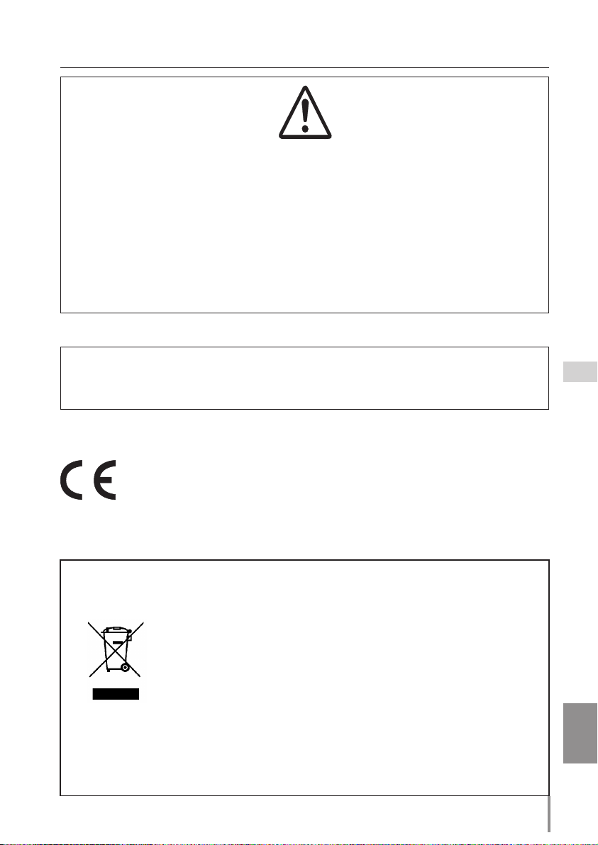
Real Time Capture function (☞p.72)
To display the screen image of
the compute r by the projec
tor through the network in real
time.
Features
Network Viewer function (☞p.87)
To acquire the JPEG image data
from the file servers placed in
the network and project them
by the projector.
PC4PC3
PC6
Capture
PC5
PC1
PC2
PC4PC3
PC6
PC5
PC1
PC2
FTP file server
JPEG
Prog.
JPEG
PJ2
PJ1
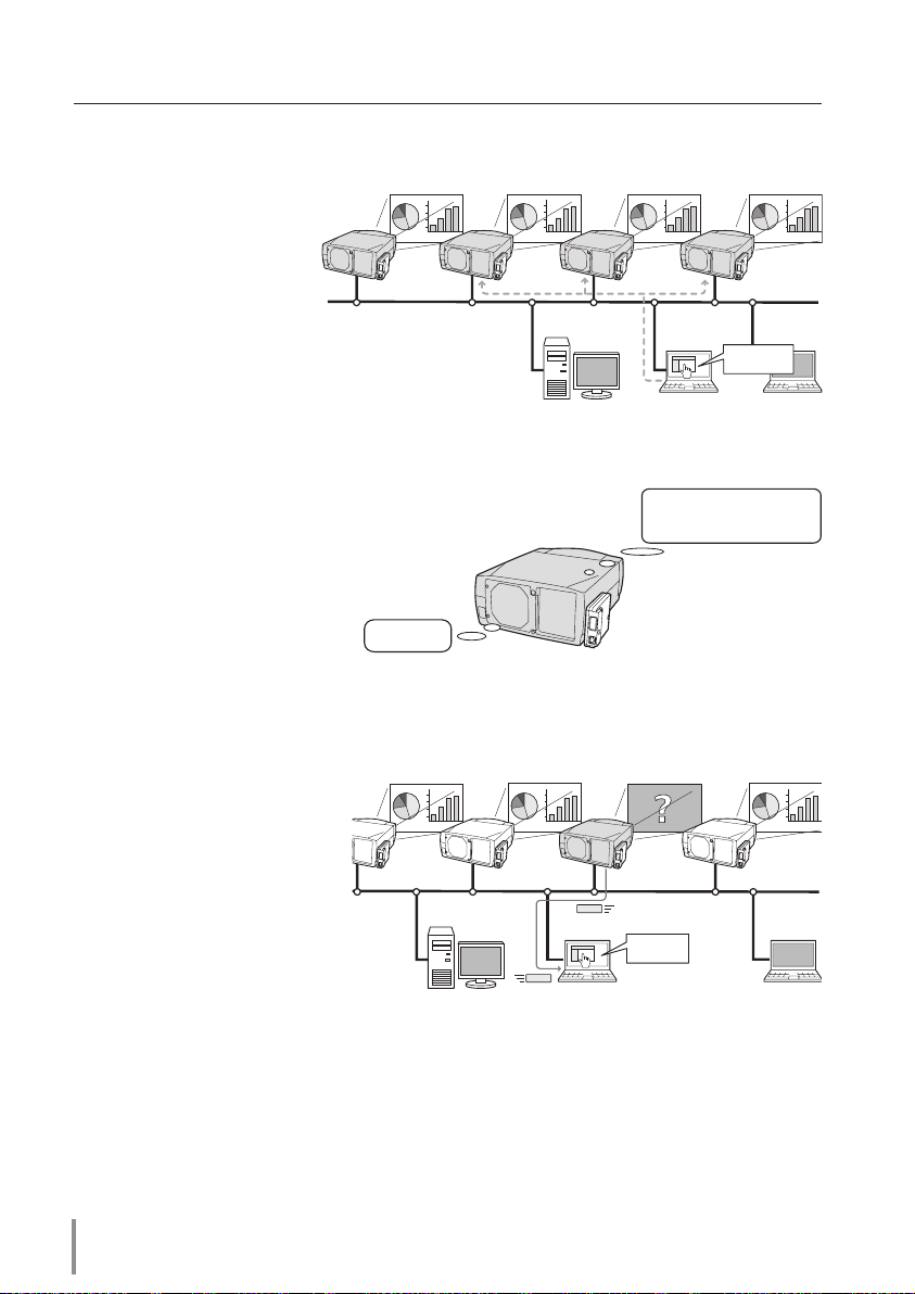
Network Communication function (☞p.77)
To communicate by sharing the
captured image of a computer
with multiple computers and
a projector. User can draw the
text and figure on the captured
image by using a drawing tool.
PC2
PC6
Capture
PC5
PC1
PJ1
Capture a screen
image of PC5 and
make marking with
a tool.
9
PJ-NET ORGANIZER
OWNER'S MANUAL
ENGLISH
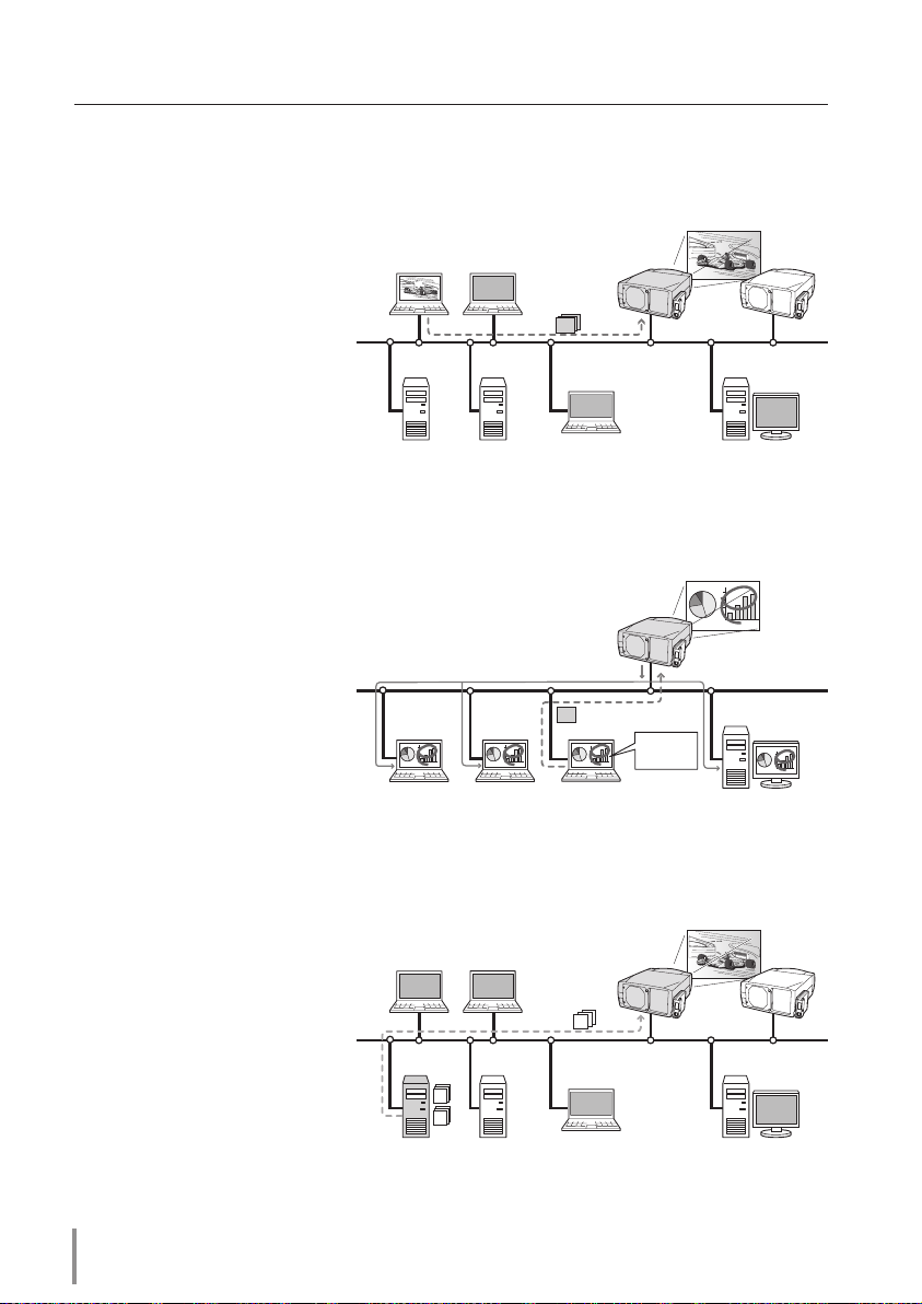
E-Mail Alert function (☞p.38)
The projector (Network Unit)
sends messages to the regis
tered e-mail addresses when
a lamp abnormalit y or power
failure occurs with the projec
to r. This message descri bes
how to solve the cause of the
problems. You can take efficient
action for quick recovery.
PC4PC3
PC6
PC5
PC1
PC2
You’ve got
Mail.
PJ2
PJ1
Web Management function (☞p.45)
With this func tion, you can
mo ni tor projec tor functions
su ch as power st atus, lamp
stat us, in pu t mod e, sig na l
condition, lamp-use time, etc.
through the network by using
the web browser installed on
your computer.
PC4PC3
PC6
PC5
PC1
PC2
Turn ON PJ2
PJ2
PJ1
Features
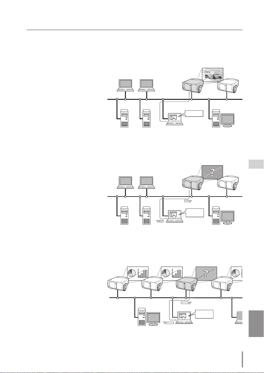
SNMP Agent function (☞p.42)
To send the information of the
projector to the SNMP manager.
Enables you to manage the projector condition with the SNMP
manager software.
PJ1
PC6
PC4
PJ2
PJ3
PJ4
PC5
You received
a Trap.
SNMP Manager
Trap
Trap
10
Chapter 1 Preparation
Multi-control function (☞p.62)
A single computer can control and set up the multiple
projectors at the same time.
PJ1
PC6
PC4
PC5
Select Input2 for
PJ1 to P
J4.
PJ2
PJ3
PJ4
Automatic On/Off using Clock function (☞p.57)
Automatically turn on or of f the
projectors at specified date/day
and time by using the clock function.
Now it’s 11:30
I am ready to turn ON,
and select Input 3 (Video)
SNMP Manager function
A f unc tio n to man ag e the
condition of projectors in the
ne twork by using the SNMP
protocol. The managing com
put er ne ed s to provi de an
SNMP managing software. Refer
to the owner's manual of the
"PJ Network Manager" supplied
separately for further details.
PC6
PC4
PJ2
PJ3
PJ4
PC5
You received
a Trap.
SNMP Manager
Trap
Trap

11
PJ-NET ORGANIZER
OWNER'S MANUAL
ENGLISH
Standard mode
Operating System
Windows 98, Windows Me, Windows NT4.0SP6
Windows 2000, Windows XP
Computer environment
Recommended CPU
Higher than Pentium III 900MHz
Memory
64MB (Minimum)/ 128MB or more(Recommended)
128MB or more for WindowsXP
HDD free area
100MB or more
Drive equipment
CD-ROM drive
Display setting of
computer
Support one of following resolutions;
VGA (640 x 480), SVGA(800 x 600), XGA(1,024 x 768) Number of col
-
ors: Either of 16 bit (65,536 color 24/32 bit (16,77 million colors))
Network card
The computer must provide a 10Base-T or 100Base-TX network
card.
Web Browser*
Internet Explorer version 5.0, 5.5 or 6.0
Netscape Navigator version6.2, 7.0 or 7.1
* Used to control and set up the projector. The layout of pages in
the browser may slightly differ from each type of application or
operating system you use.
Plug-Ins
Macromedia Flash Player version 6,0,79,0(6.0r79) or later
Internet Mailer*
- Microsoft Outlook - Microsoft Outlook Express
- Netscape Mail
* Required the internet e-mail application software to receive an
e-mail alert sent from this product. If you do not use the function
E-mail Alert, this application is not required.
FTP Service *
- FTP server (Windows 2000 Professional or Windows XP
Professional)
* The FTP service provided with the Windows 2000 Professional
or Windows XP Professional is required when using the Network
Viewer function.
Operating environment
To perform the managing and setting of the projector by using this product, the environment described below is required.
*1 The "Light Mode" and "Standard Mode" will be explained on item "Display Mode" (☞ p.30-32)
Operating Environment
PDA restriction
Th e PDA can be used for the Light mode*1 only. The operating system of the PDA is
PocketPC2002 or higher. The version of the Macromedia Flash Player is 6,0,81,0 or higher.
Please consult your local dealer for the information about the compatibility of this network unit and your projectors.
12
Chapter 1 Preparation
Before use
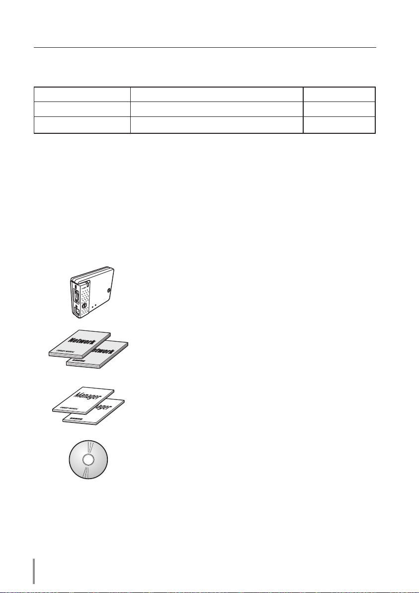
Package contains
The package contains following items. Check each item as you unpack the package. If you
have any of the following items missing, contact the sales dealer.
The limitation*1 of connection between this product and hub or computer
Suitable LAN cables are limited by length and type as follows;
Connection Type of usable LAN cable Maximum length
Network Unit - Hub UTP Straight Cable with category 3 or 5 *
2
100m
Network Unit - Computer UTP Cross Cable with category 3 or 5*
2
100m
*1 There may be other limitations depending on your network environment or LAN specification.
Please consult your network administrator for further details.
*2 Category of LAN cable indicates the cable quality. Normally, a cable with category 3 or 5 is used
for 10Base-T network, and a cable with category 5 is used for 100Base-TX network.
L
I
N
K
A
C
T
❑ Network unit 1 piece
❑ CD-ROM 1 piece
Network Viewer & Capture 3 software
PJ Network Manager software
❑ PJ Network Manager Owner’s manual
English/Japanese 1 piece each
❑ PJ-Net Organizer Owner’s manual
English/Japanese 1 piece each

13
PJ-NET ORGANIZER
OWNER'S MANUAL
ENGLISH
Notice
Expression/Abbreviation
The word "projector" found in this manual means "projector provided with Network unit"
unless otherwise noted.
The OS of the computer and the Web browser described in this manual is Windows XP
Professional and Internet Explorer 6.0. In case of another OS or Web browser, some instruc
-
tion procedures may differ from the actual operation depending on your computer envi
-
ronment.
Use of this manual
This manual does not provide the description of basic operation and functions for computer, web browser, projector and network. For instructions about each piece of equip
-
ment or application software, please refer to the respective booklet.
Trademarks
Ethernet is a registered trademark of Xerox Corporation. Microsoft, Windows, Windows
NT are registered trademarks of Microsoft Corporation. Internet Explorer is a registered
trademark of Microsoft Corporation. Netscape Navigator and Netscape Communicator are
trademarks or registered trademarks of Netscape Communications Corporation. JavaScript
is a registered trademark of Sun Microsystems, Inc. PJLink is a registered trademark of
JBMIA (Japan Business Machine and Information System Industries Association).
Other product or brand names in this manual are registered trademarks or trademarks of
their respective owners.
* Unauthorized use of a part or whole of the contents in this manual is prohibited.
* The contents of this manual are subject to change without notice.
Before use

14
Chapter 1 Preparation

PJ-NET ORGANIZER
OWNER'S MANUAL
ENGLISH
PJ-NET ORGANIZER
OWNER'S MANUAL
15
ENGLISH
Chapter 2
Installation
2
Describes how to install the network unit and software, and configure the network.

16
Chapter 2 Installation
The following are instructions for attaching this product to the projector and connecting it
to the network. Please review the entire procedure to become familiar with it.
Function of the network unit (☞ p.17)
1
Installation and network configuration (☞ p.18-24)
2
Installation of the software (☞ p.25-27)
3
Set up is complete
1 Mount this product onto the projector.
2 Connect the LAN cable and join it to the network.
3 Configure the network of the network unit.
4 Set the Network PIN code.
Explains how to install the software Network Viewer & Capture 3 into your computer.
Flow of installation
The preparation is completed to control the projector connected to the network. At next
step, set up and control the projector via the network by using the web browser installed
on your computer. Please see chapter 3 "Basic setting and operation". (☞ p.29)
Explains the name and functions of each part of the network unit.
17
PJ-NET ORGANIZER
OWNER'S MANUAL
ENGLISH
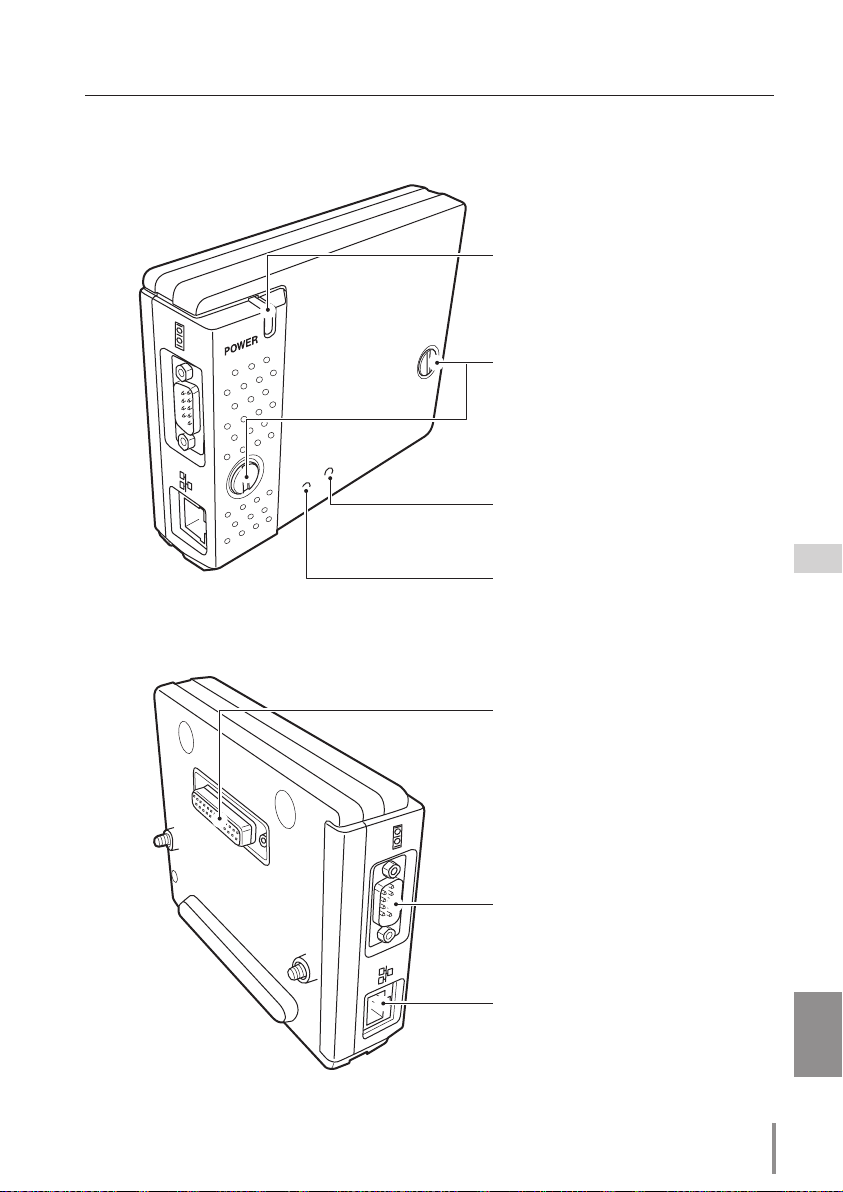
Name and function of each part
[1] Name and function of each part
LINK
AC
T
Serial port
Used to control the external equipment
via the network. (
☞ p.105)
POWER indicator
This lights up red when the network
function is set ON in the projector
menu.
LAN port
Connecting the LAN cable. (☞ p.19)
Connector plug
Connecting to the terminal on the projector. (
☞ p.18)
Mounting screws
Mount by using a coin etc. (☞ p.18)
LINK indicator
This lights up red when the network unit is
connected to the network correctly.
ACT indicator
This turns on and off with green when
sending or receiving of data
(Top View)
(Bottom View)
18
Chapter 2 Installation
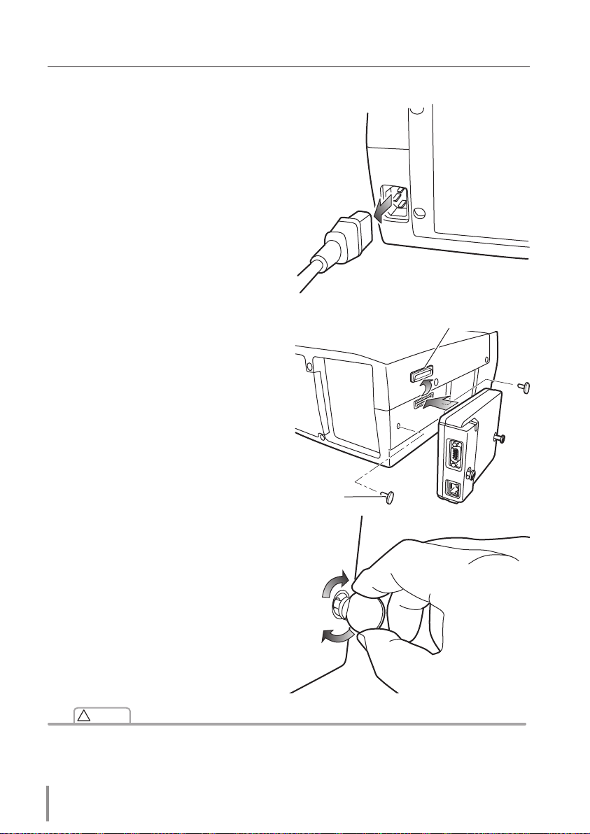
Mounting
✐ AC cord must be disconnected when mounting or removing this product otherwise it may dam-
age the product.
✐ Do not install multiple network units into a projector otherwise it may damage the product.
✐ Connect the AC cord after connecting the LAN cable and computer.
[2] Installation and network configuration
Caution
!
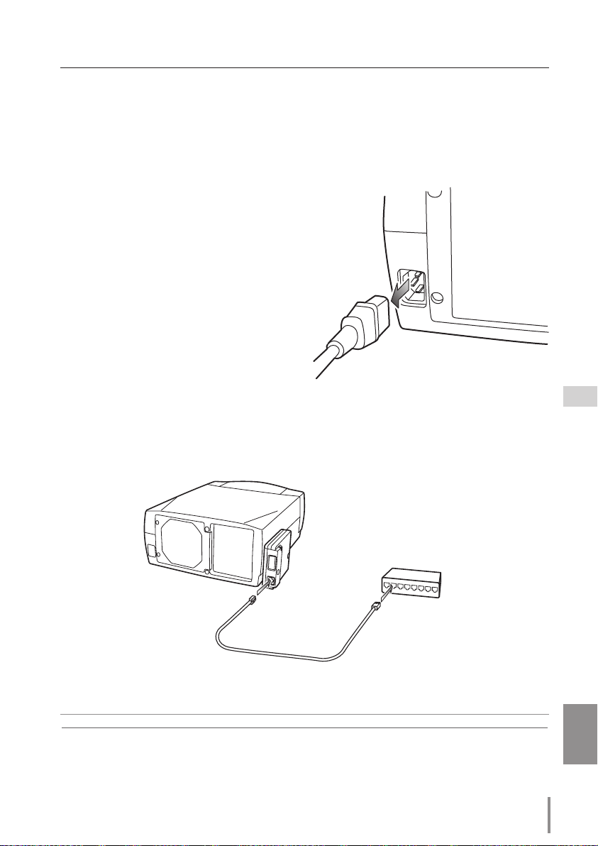
1 Disconnect the AC plug from the projector.
2 Remove the connector cover and screw
covers (2 pieces) from the projector and
insert plug on this product to the option
connector.
3 Tighten two screws by using a coin
etc.
Connector cover
Screw cover
19
PJ-NET ORGANIZER
OWNER'S MANUAL
ENGLISH
Connection of LAN cable
To connect to the network, it is required to use the UTP (Unshielded Twisted Pair) straight cable
with RJ-45 plug. There are two different types of cables depending on whether the network is
constructed with 10Base-T or 100Base-TX. Prepare the Hub (10Base-T or 100Base-TX) to distrib
-
ute the network cable if required.
1 Disconnect the AC plug from the projector.
2 Connect the UTP straight cable to the LAN
port on the network unit.
3 Connect the UTP straight cable to the hub.
✐ Use the UTP cross cable when you connect the computer and projector directly not using the
hub.
✐ When you connect the projector into the 10Base-T network, use cable with category 3 or 5. When
you connect the projector into the 100Base-TX network, use cable with category 5.
✐ The length of cable between hub and projector should be less than 100m.
Hub
(10Base-T, 100Base-TX)
UTP straight cable
Projector
Installation and network configuration
20
Chapter 2 Installation
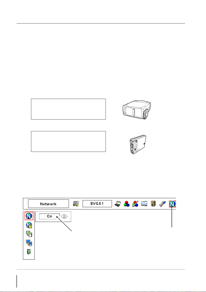
1 Selection of network menu
Turn on the projector and display the menu on the screen. Select network icon from the
main menu and then press SELECT button once. Check that the mode is "On". If not,
change mode to "On" using the point buttons (7,8).
Network configuration
Confirmation of the network menu
When installing this product to the projector, the network on-screen menu items for this
product are activated automatically. If not activated, the product may not have been
installed correctly. Please check item "Mounting" (☞ p.18).
Configure the network
Before performing the network configuration, prepare network address numbers (IP
Address, Subnet Mask, Default Gateway, DNS) assigned to the projector. Ask your network
administrator for the network address.
For example, the case where the following network address is set up is explained.
IP Address : 192.168.1.201
Subnet Mask : 255.255.255.0
Default Gateway : 192.168.1.1
DNS : 0.0.0.0
The default network configuration is set as follows.
IP Address : 192.168.0.2
Subnet Mask : 255.255.255.0
Default Gateway : 0.0.0.0
DNS : 0.0.0.0
L
I
N
K
A
C
T
Network icon
Select "On" or "Off"
with 7,8 button
✐ The network unit begins restarting each time the mode is set "On".
21
PJ-NET ORGANIZER
OWNER'S MANUAL
ENGLISH
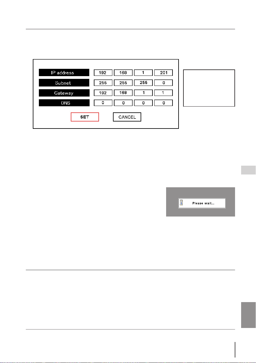
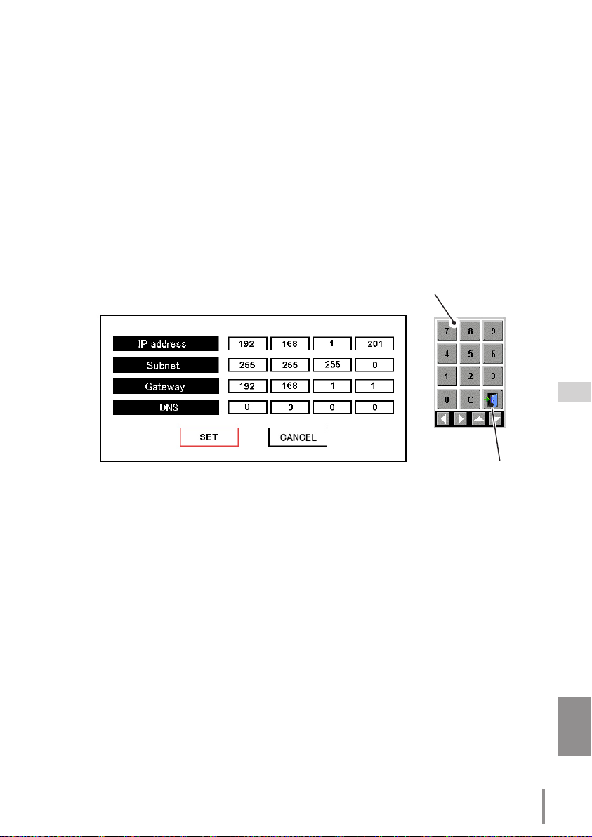
2 Configuration for IP Address/ Sub net/ Gateway*
1
/DNS*
2
Press SELECT button again. The following network setting pallet appears on the screen.
Enter the specified network addresses.
How to enter the numbers
There are 2 ways to enter the numbers, one is by using the point buttons (d e ) on
the remote control or on the projector, the other is by using the screen 10-key pallet by
which the numbers can be entered directory. For further information see "How to enter
the numbers with the screen 10-key pallet" (
☞ p.23).
3 Fixing the network configuration
After completing the entering of address, select "SET" and
press SELECT button.
The network unit starts re-booting
and displays message "Please wait..." on the screen until
the re-booting is complete.
Do not disconnect the AC
cord during this period. After that the network setting pallet will disappear on the screen.
Completing of installation
Now the installation is complete. The IP address of this projector is set to "192.168.1.201".
Item Description
IP address .............Sets IP address of the projector
Sub net ...................Sets Subnet mask. Normally sets 255.255.255.0
Gateway*
1
............. Sets IP address of the default gateway (Router)
DNS*2 .......................Sets IP address of the DNS server. Must be set when using the e-mail function
*1 In the network environments not using a Gateway or Router, the Gateway address should be set to [0.0.0.0].
*2 If you do not use the functions E-mail or DNS server, it is also set [0.0.0.0] for the DNS address.
✐
Refer to the projector's owner's manual for operation of the projector.
Installation and network configuration
The red frame moves
sequentially left or right
with
7 8 button.
The number up or
down with d e button.
22
Chapter 2 Installation
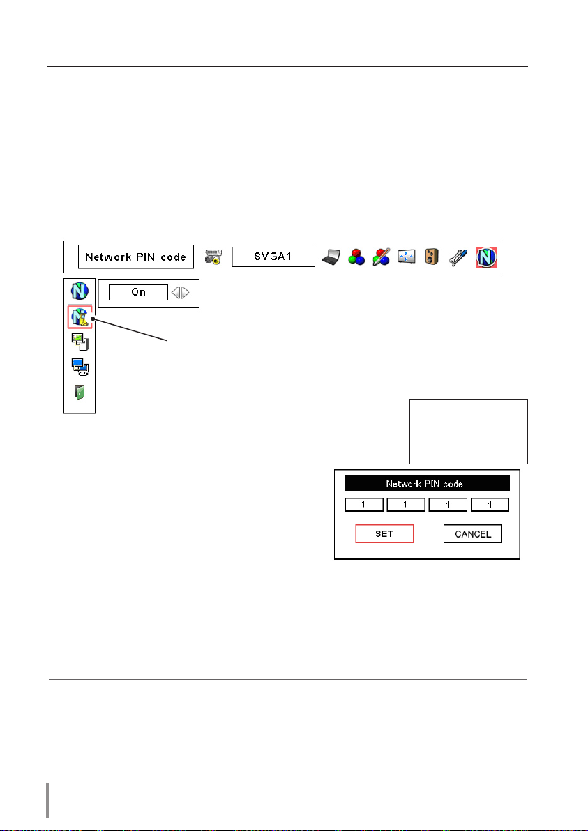
Network PIN code setting
The Network PIN code can be set to restrict access to the setting page of the projector
using the web browser.
✐ Default Network PIN code [0000] means no Network PIN code is set.
1 Displaying Network PIN code menu
Select network menu and then select "Network PIN code" sub menu. Press SELECT button twice to display the Network PIN code entry pallet.
* The number on the pallet is the current Network PIN code.
2 Entering the Network PIN code
To enter the Network PIN code, use point buttons
(▲,▼,7,8) on the projector or the remote con-
trol.
3 Fixing the Network PIN code
After entering a 4-digit number, select "SET" by
using point buttons (
7,8) and then press SELECT
button.
✐ The screen 10-key pallet can be used for entering the Network PIN code. See item "How to enter
the numbers with the screen 10-key pallet" (
☞. 23)
✐ It is recommended to set up the Network PIN code when you connect the projector to the net-
work. This setting is carried out through the projector’s menu and also it can be set through the
network using the web browser. For further information, refer to item "Initial Setting/Network PIN
code setting" (
☞ p.35).
✐ Valid characters for the Network PIN code are only numbers 0 to 9. The number "0000" means no
Network PIN code is set.
✐ This Network PIN code is not to restrict the use of the projector. This Network PIN code is to set
the security against the use of the projector through the network.
Network PIN Code
The red frame moves
sequentially left or right
with 7 8 button.
The number up or down
with d e button.
23
PJ-NET ORGANIZER
OWNER'S MANUAL
ENGLISH
How to enter the numbers with the screen 10-key pallet
1 Select a column with a red frame by using the point buttons 7 8 .
2 Press SELECT button. The screen 10-key pallet appears on the screen.
3 By using the point buttons(d e 7 8), select numbers 0 to 9 and press SELECT button. By
repeating the above to enter the complete number on the column.
* To change the number in a column, select “C” and press SELECT button to clear the number in
the column and then enter the number again.
4 After entering the number in the column, select a move key (7 8 e d) located on the lower
part of the pallet by using the point buttons and press
SELECT button repeatedly to move
the red frame.
5 Repeat steps 3 to 4 for entering all the network address.
6 After finishing, select "Exit" and press SELECT button. The 10-key pallet disappears on the
screen.
Installation and network configuration
Exit
10-key pallet

24
Chapter 2 Installation
Notice about system construction
For installation of multiple projectors into the same network with network
unit.
Do not install multiple projectors with network units that have their default network settings to the same network. The use of the network units which have the default IP address
set to the same network settings will cause IP addresses to collide and create a malfunction. When you install multiple projectors into the same network, configure the network
with the following steps.
1. Change the IP address from the default IP address. To change the IP address, use the
network setting menu on the projector. Please see item "Network configuration" for fur
-
ther information (
☞ p.20).
2. Make sure that there is no network equipment set with the same IP address in the net
-
work before connecting to the network.
3. When installing other projectors, follow the above steps to change the IP address and
connect to the network.
In case of installing the projector with network unit into the network constructed with the DHCP/BOOTP server.
This network unit does not support the DHCP/BOOTP server. The static IP address must be
manually configured. To use this product in this network environment, set it up so that the
DHCP/BOOTP server does not assign the IP address configured to this product for another
device on the network. Please consult your network administrator for further information.
25
PJ-NET ORGANIZER
OWNER'S MANUAL
ENGLISH
Installation and network configuration
[3] Installing the software
It is required to install the software into your computer to use the Network Capture function and Network Viewer function. Please install the software as follows.
Note: To install the software into the computer with Windows 2000, Windows XP
or Windows NT, you should logon as administrator. Before installation, make
sure that the other applications are closed, otherwise proper installation
cannot be made.
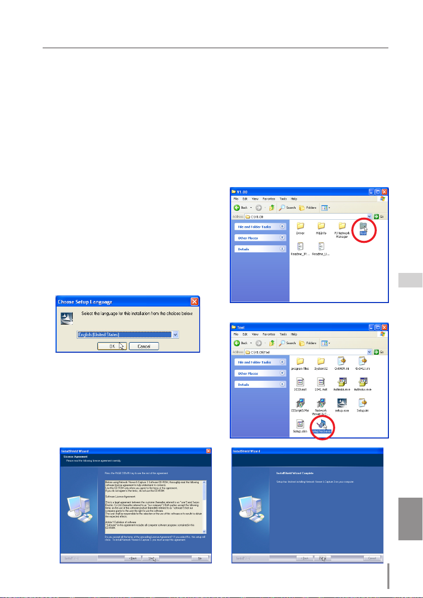
Network Viewer & Capture 3 installation
1 Set the supplied Network Viewer & Capture
3 CD-ROM into the CD-ROM drive of your
computer. Double click SetupTool.exe icon in
the "Tool" folder in the CD-ROM.
2 Select "English [United States]" from the
pu ll-d own menu on the "Choose Setup
Language" window and click OK button to
start installing and then follow the installa
-
tion wizards.
As the "License Agreement" will appear, read
contents carefully and click Yes button if you
agree to the license agreement to proceed
with installing.
26
Chapter 2 Installation
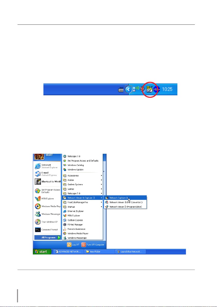
Installed software
The following 3 software are installed on your computer.
● Network Capture 3:
Capture the displayed image of the computer and serve it to the projector via the network.
This software is registered into "startup folder" of the computer and the capture icon
stays on the task bar after booting the computer.
● Network Viewer 3 (File Converter 1):
Converts to the JPEG*1 data format which can be projected with the projector from the
JPEG, bitmap and Power Point files.
● Network Viewer 3 (Program Editor) :
This is a tool to make the program which has a function to specify and order the projecting JPEG image data stored in the file servers.
* To uninstall these software, use "Add/Remove Program" from the control panel.
*1 This product supports the JPEG image format. This file is needed to convert to the optimized JPEG
file by using the File Converter 1 software previously. Refer to the item "Creating the available data
[Network Viewer 3]"(
☞p.88) about data converting for the projection.
27
PJ-NET ORGANIZER
OWNER'S MANUAL
ENGLISH
Installing the software
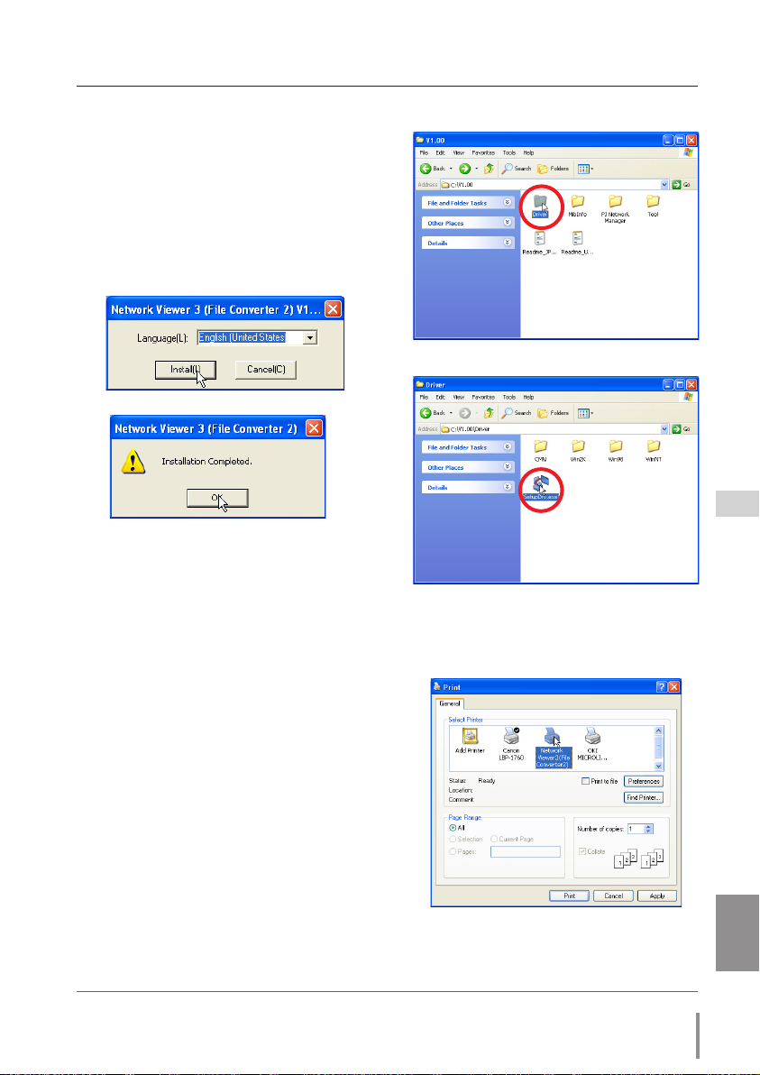
File Converter 2 Installation
1 Set the supplied Network Viewer & Capture
3 CD-ROM into the CD-ROM drive of your
computer. Double click SetupDrv.exe icon
in the "Driver" folder in the CD-ROM.
2 Select "English [United States]" from the
pull-down menu on the language selection
window and then click Install button to start
installing.
Installed software and places
Network Viewer 3 (File Converter 2) is installed in the
"Printers and Faxes" folder in the "Control Panel".
● Network Viewer 3 (File Converter 2):
This is a kind of the printer driver to convert
to the JPEG data optimized to project by the
projector from any of the documents created
by the application software.
* To uninstall this software, just delete the "Network Viewer" icon from the "Printers and faxes" folder.

28
Chapter 2 Installation

PJ-NET ORGANIZER
OWNER'S MANUAL
ENGLISH
PJ-NET ORGANIZER
OWNER'S MANUAL
29
ENGLISH
Chapter 3
Basic Setting and Operation
3
Describes basic operations and settings for controlling the projector by using the web browser. It is required that computer and
projector is connected to the network and the network address is
properly configured.
30
Chapter 3 Basic Setting and Operation
Login the setting page of the projector
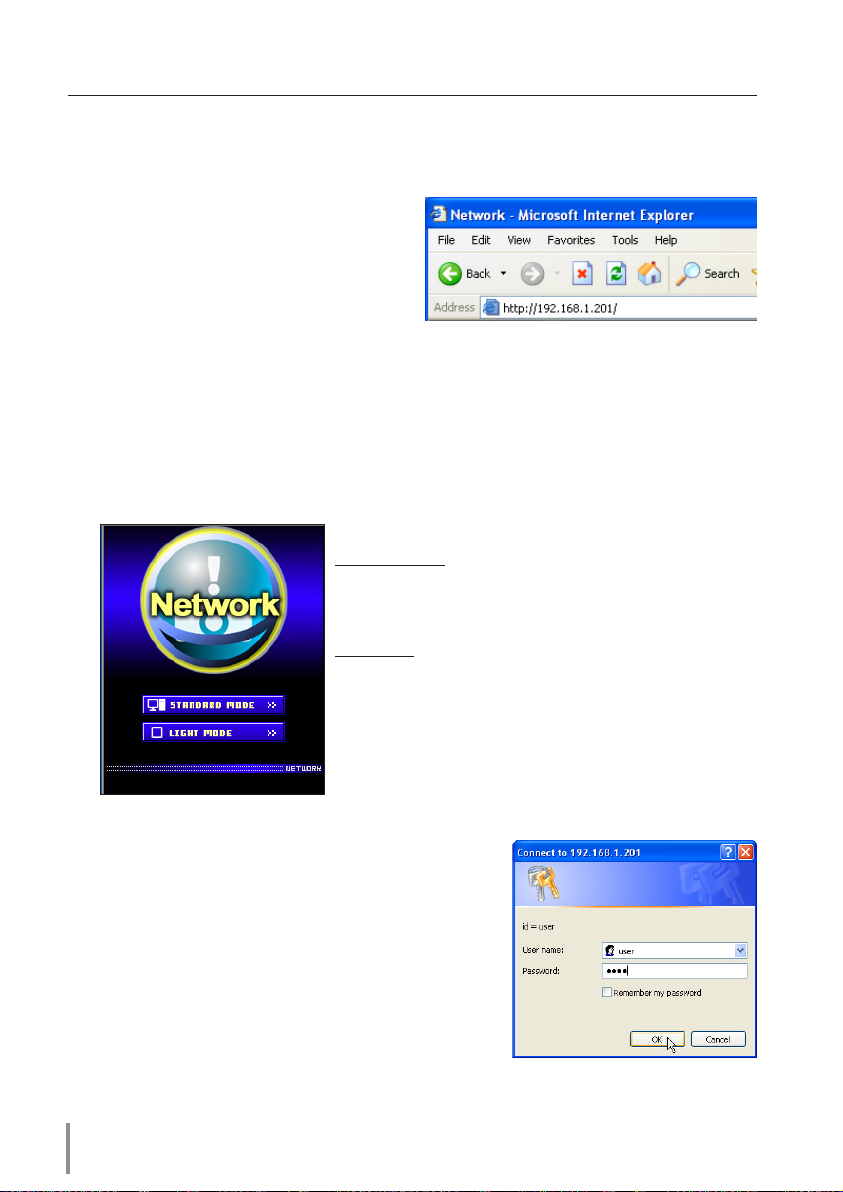
1 Enter the IP address
Launch the web browser installed in your
computer, enter the IP address into the
"Address" on the browser and then press
"Enter" key.
Enter the address (192.168.1.201) that you
configured in item "Network configura
-
tion" (
☞ p.20). The default IP address is [192.168.0.2].
2 Select a display mode and login
This product provides 2 types of control mode, Standard Mode and Light Mode as the
below. Select a proper mode to match your PC and network environment by clicking
on the text link.
STANDARD
MODE Fo r co mpute r displ ay, di splay s
graphical menus and settings. This
mode is recommended for standard
use.
LIGHT MODE Displays with 200 x 300 dots. This
mode is optimized for use of the
handheld computer, PDA, etc. It is
also convenient if the network traf
fic is heavy. (This mode has some
limitations on the network viewer
and multi-control functions.)
If the se ttin g page has set the pass word, the
authentication window will appear. In this case type
"user" onto the User Name text area and the login
Network PIN code onto the Password text area and
then click OK button.
* The entering User Name must be "user" and it can not be
changed.
[Note]
When accessing the projector for the first time or the
Network PIN code "0000" is set, the auto-login will be per
-
formed and the next main setting page is displayed.
 Loading...