

Page 1
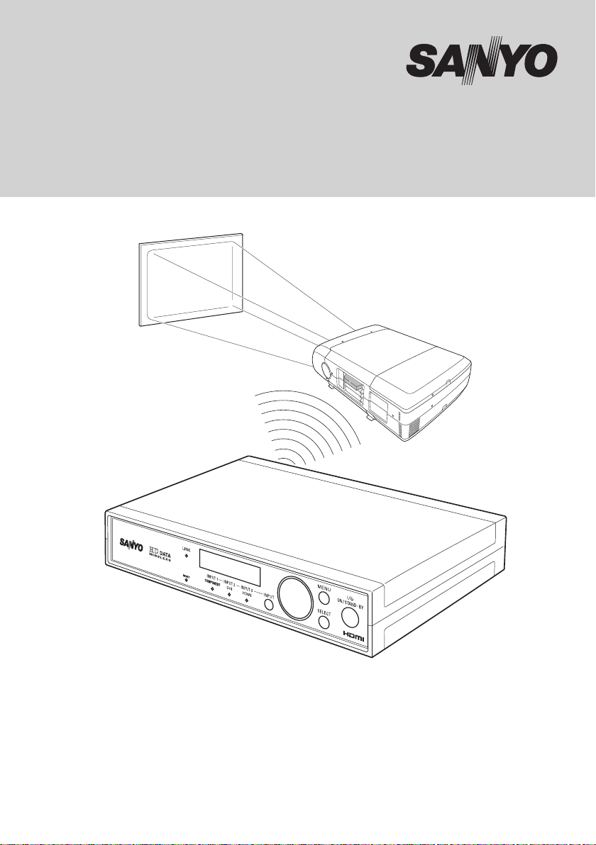
Owner’s Manual
HD DATA WIRELESS Transmitter Box
Model POA-HDTM01
Page 2
ID = B
ID = B
Single Mode
Single Mode
ID = A
ID = A
Single Mode
Single Mode
ID = A
ID = A
ID = A
ID = A
Broadcast Mode
Broadcast Mode
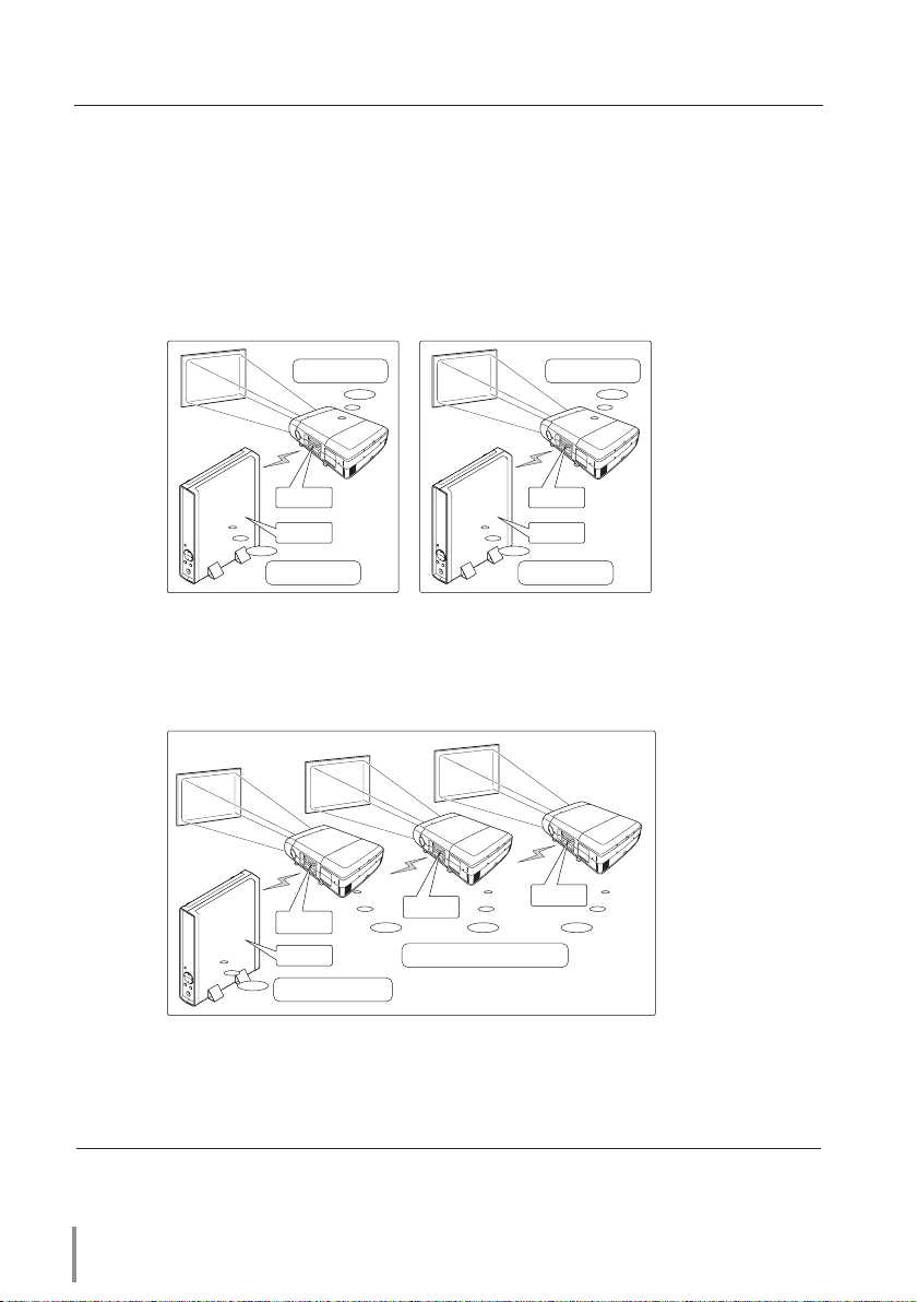
Features and Design
This transmitter POA-HDTM01 can be used on the specified projector with the receiver
board POA-MD26HDWL installed.
The image from the peripheral equipment is transferred to each projector via wireless
network. There is no need for wire connection between the transmitter and the projector.
You can select one of 2 installation modes as follows.
Single Mode
This mode is available only between one transmitter and one receiver.
Broadcast Mode
This mode is available between one transmitter and 2 or more receivers. It is useful to
project the same images to multiple screens.
✐ When selecting "INPUT 3 HDMI", only Single Mode is available. "INPUT 3 HDMI" cannot be selected in
the Broadcast Mode.
✐ The projector in this manual is PLC-XF47 for example.
2
Page 3

Table of Contents
Features and Design . . . . . . . . . . . . . . . . . . . . . . . . . . . . . . . . . . . . . . . . . . . . . . . . . . . . . . . . 2
Table of Contents . . . . . . . . . . . . . . . . . . . . . . . . . . . . . . . . . . . . . . . . . . . . . . . . . . . . . . . . . . . 3
To the Owner . . . . . . . . . . . . . . . . . . . . . . . . . . . . . . . . . . . . . . . . . . . . . . . . . . . . . . . . . . . . . . . 4
Safety Instructions . . . . . . . . . . . . . . . . . . . . . . . . . . . . . . . . . . . . . . . . . . . . . . . . . . . . . . . . . . 5
Compliance. . . . . . . . . . . . . . . . . . . . . . . . . . . . . . . . . . . . . . . . . . . . . . . . . . . . . . . . . . . . . . . . . 8
Preparation . . . . . . . . . . . . . . . . . . . . . . . . . . . . . . . . . . . . . . . . . . . . . . . . . . . . . . . . . . . . . . . . 11
Before use 11
Part Names and Functions 12
Installation . . . . . . . . . . . . . . . . . . . . . . . . . . . . . . . . . . . . . . . . . . . . . . . . . . . . . . . . . . . . . . . .14
Connection to external equipment 14
Connecting the AC Power Cord 15
Installing the Receiver into the Projector 16
Basic Setting and Operation . . . . . . . . . . . . . . . . . . . . . . . . . . . . . . . . . . . . . . . . . . . . . . . .17
Projector Operation 17
Turning on the Transmitter 18
Turning off the transmitter 18
Input Source Selection 19
How to Operate the Menu 19
Menu Tree 20
Flow of Installation Mode 21
Single Mode Operation . . . . . . . . . . . . . . . . . . . . . . . . . . . . . . . . . . . . . . . . . . . . . . . . . . . .22
6/6: Mode Select & 1/6: Single Mode Setup 22
Broadcast Mode Operation. . . . . . . . . . . . . . . . . . . . . . . . . . . . . . . . . . . . . . . . . . . . . . . . .26
6/6: Mode Select & 4/6: ID Number 26
Other Basic Operation. . . . . . . . . . . . . . . . . . . . . . . . . . . . . . . . . . . . . . . . . . . . . . . . . . . . . . 30
5/6: Key Lock 30
2/6: Image Adjust 32
3/6: Information 32
Reset Function of the projector 33
Maintenance and Care . . . . . . . . . . . . . . . . . . . . . . . . . . . . . . . . . . . . . . . . . . . . . . . . . . . . . 34
Appendix. . . . . . . . . . . . . . . . . . . . . . . . . . . . . . . . . . . . . . . . . . . . . . . . . . . . . . . . . . . . . . . . . . 35
Troubleshooting 35
Specifications 36
Compatible Signals Specifications 38
Configurations of Terminals 39
English
HD DATA WIRELESS TRANSMITTER BOX
OWNER'S MANUAL
3
Page 4
To the Owner
Before operating this transmitter, read
this manual thoroughly and operate the
transmitter properly.
Operating the transmitter properly
enables you to manage those features
and maintains it in better condition for a
considerable time.
Improper operation may result in not
only shortening the product-life, but
also malfunctions, fire hazard, or other
accidents.
If your transmitter seems to operate
improperly, read this manual again, check
operations and cable connections and
try the solutions in the "Troubleshooting"
section in the end of this manual. If the
problem still persists, contact the dealer
where you purchased the transmitter or the
service center.
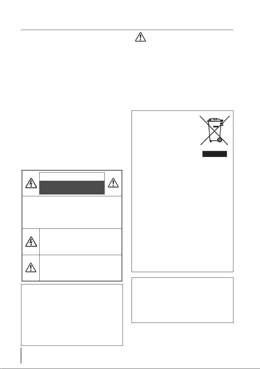
CAUTION
RISK OF ELECTRONIC SHOCK
DO NOT OPEN
CAUTION : TO REDUCE THE RISK OF
ELECTRIC SHOCK, DO NOT
REMOVE COVER. REFER
SERVICING TO QUALIFIED
SERVICE PERSONNEL.
THIS SYMBOL INDICATES THAT
DANGEROUS VOLTAGE CONSTITUTING
A RISK OF ELECTRIC SHOCK IS
PRESENT WITHIN THIS UNIT.
THIS SYMBOL INDICATES THAT THERE
ARE IMPORTANT OPERATING AND
MAINTENANCE INSTRUCTIONS IN THE
OWNER'S MANUAL WITH THIS UNIT.
Important Notice
There are restrictions on the channels
and frequencies in the countries and
regions at which you can use the wireless
communication. So it is forbidden to take
the transmitter and the receiver outside
the country or region where you purchased
them.
4
Safety Precaution
WARNING: TO REDUCE THE RISK OF
FIRE OR ELECTRIC SHOCK,
DO NOT EXPOSE THIS
APPLIANCE TO RAIN OR
MOISTURE.
– If the transmitter is unused for an
extended time, unplug the transmitter
from the AC power outlet.
NOTE:
This symbol and recycle
system are applied only
to EU countries and not
applied to the countries
in the other area of the
world.
Your SANYO product is designed and
manufactured with high quality materials
and components which can be recycled
and reused.
This symbol means that electrical and
electronic equipment, at their end-of-life,
should be disposed of separately from
your household waste.
Please dispose of this equipment at
your local community waste collection/
recycling centre.
In the European Union there are separate
collection systems for used electrical and
electronic products.
Please help us to conserve the
environment we live in!
SANYO FISHER Sales (Europe) GmbH
Stahlgruberring 4, D-81829 München,
Germany
SANYO Electric Co., Ltd.
1-1, Sanyo-cho, Daito City, Osaka
574-8534, Japan
READ AN D KEEP THIS OWNER'S
MANUAL FOR LATER USE.
Page 5

Safety Instructions
All the safety and operating instructions
should be read before the product is
operated.
Read all of the instructions given here
and retain them for later use. Unplug this
transmitter from AC power supply before
cleaning. Do not use liquid or aerosol
cleaners. Use a damp cloth for cleaning.
Follow all warnings and instructions marked
on the transmitter.
For added protection to the transmitter
during a lightning storm, or when it is left
unattended and unused for long periods
of time, unplug it from the wall outlet. This
will prevent damage due to lightning and
power line surges.
Do not expose this unit to rain or use near
water... for example, in a wet basement,
near a swimming pool, etc...
Do not use attachments not recommended
by the manufacturer as they may cause
hazards.
Sl ots and op eni ngs in the back an d
bottom of the cabinet are provided for
ventilation, to ensure reliable operation
of the equipment and to protect it from
overheating.
The openings should never be covered with
cloth or other materials, and the bottom
opening should not be blocked by placing
the transmitter on a bed, sofa, rug, or other
similar surface. This transmitter should
never be placed near or over a radiator or
heat register.
This transmitter should not be placed in
a built-in installation such as a book case
unless proper ventilation is provided.
Never push objects of any kind into this
transmitter through cabinet slots as they
may touch dangerous voltage points or
short out parts that could result in a fire or
electric shock. Never spill liquid of any kind
on the transmitter.
Do not install the transmitter near the
ve ntilation duct of air-condi tioning
equipment.
English
Do not place this transmitter on an unstable
cart, stand, or table. The transmitter may
fall, causing serious injury to a child or adult,
and serious damage to the transmitter. Use
only with a cart or stand recommended
by the manufacturer, or sold with the
transmitter. Wall or shelf mounting should
follow the manufacturer's instructions, and
should use a mounting kit approved by the
manufacturers.
An ap pli a nce a nd c ar t
combination should be
moved with care. Quick
stops, excessive force, and
uneven surfaces may cause
the a ppliance and cart
combination to overturn.
This transmitter should be operated only
from the type of power source indicated
on the marking label. If you are not sure of
the type of power supplied, consult your
authorized dealer or local power company.
Do not overload wall outlets and extension
cords as this can result in fire or electric
shock. Do not allow anything to rest on the
power cord. Do not locate this transmitter
where the cord may be damaged by
persons walking on it.
Do not attempt to service this transmitter
yourself as opening or removing covers may
expose you to dangerous voltage or other
hazards. Refer all servicing to qualified
service personnel.
HD DATA WIRELESS TRANSMITTER BOX
OWNER'S MANUAL
5
Page 6

Safety Instructions
Unplug this transmitter from wall outlet and
refer servicing to qualified service personnel
under the following conditions:
a. When the p ower cord or p lug i s
damaged or frayed.
b. If li quid has been spilled into the
transmitter.
c. If the transmitter has been exposed to
rain or water.
d. If the transmitter does not operate
normally by following the operating
instructions. Adjust only those controls
that are covered by the operating
instructions as improper adjustment
of other controls may result in damage
and will often require extensive work
by a qualified technician to restore the
transmitter to normal operation.
e. If the transmitter has been dropped or
the cabinet has been damaged.
f. When the transmitter exhibits a distinct
change in performance-this indicates a
need for service.
When replacement parts are required,
be sure the s e rvi ce techn i cian ha s
us ed repla cement par ts spe cified by
the manufacturer that have the same
character istics as the original part .
Unauthorized substitutions may result in
fire, electric shock, or injury to persons.
Upon c ompletion of any se rvice or
repairs to this transmitter, ask the service
technician to perform routine safety checks
to determine that the transmitter is in safe
operating condition.
6
Page 7

Safety Instructions
CAUTION IN CARRYING OR TRANSPORTING THE TRANSMITTER AND THE
RECEIVER
- The transmitter and the receiver are precision equipment. Do not drop, bump, or subject
it to strong forces. Doing so may cause damage or malfunction of the transmitter or the
receiver.
- When transporting the projector, make sure that the receiver is removed from the
projector. Do not transport the projector with the receiver installed. To do so may cause
damage or malfunction of the receiver or the projector.
CAUTION IN HANDLING THE RECEIVER
When the receiver is inserted into the projector, the cover of the receiver protrudes from the
cabinet of the projector.
- Do not push or hit the receiver.
- Do not put anything on the receiver.
- Do not hold it when lifting or moving the projector. Doing so may cause damage to the
receiver or the projector.
CAUTION IN HANDLING THE TRANSMITTER
- Do not put anything on the cabinet of the transmitter. To do so may cause damage or
malfunction of the transmitter.
Air Circulation
- The openings in the cabinet are provided for ventilation. To ensure reliable operation of
the transmitter and to protect it from overheating, these openings must not be blocked or
covered.
- Keep the openings at least 10cm away from any objects.
English
Caution about Radio Wave
This unit operates in 5.2 GHz band, the same frequency band used for industrial, scientific,
and medical equipment (such as pacemaker).
Please make sure the following cautions.
1. Be sure that there are no other devices in the area that may use the same frequency band
as Transmitter.
2. If any other devices are causing radio interferences, move to other location.
3. Do not set up this unit outside. This unit operates in 5.2 GHz band, so it is designated for
indoor use only.
Warning
This is a class A product. In a domestic environment this product may cause radio
interference in which case the user may be required to take adequate measures.
HD DATA WIRELESS TRANSMITTER BOX
OWNER'S MANUAL
7
Page 8

Compliance
Federal Communications Commission Notice
This equipment has been tested and found to comply with the limits for a Class A digital device,
pursuant to part 15 of the FCC Rules. These limits are designed to provide reasonable protection
against harmful interference when the equipment is operated in a commercial environment.
This equipment generates, uses and can radiate radio frequency energy and, if not installed and
used in accordance with the instructions, may cause harmful interference to radio communications.
Operation of this equipment in a residential area is likely to cause harmful interference in which case
the user will be required to correct the interference at his own expense.
This device complies with Part 15 of FCC Rules and RSS-Gen of IC Rules. Operation is subject to the
following two conditions: (1) the device may not cause interference, and (2) the device must accept
any interference, including interference that may cause undesired operation of this device.
CAUTION: Properly shielded a grounded cables and connectors must be used for connection to host
computer and /or peripherals in order to meet FCC emission limits.
FCC Warning
Changes or modifications not expressly approved by the party responsible for compliance could void
the user’s authority to operate the equipment.
FCC RF Exposure Warning
- This transmitter must not be co-located or operated in conjunction with any other antenna or
transmitter.
- This equipment complies with FCC radiation exposure limits set forth for uncontrolled equipment
and meets the FCC radio frequency (RF) Exposure Guidelines in Supplement C to OET65. This
equipment must be installed and operated with at least 20cm and more between the radiator and
person’s body (excluding extremities: hands, wrists, feet and ankles).
For Canadian Users
This Class A digital apparatus complies with Canadian ICES-003.
Cet apparei numérique de la classe A est conforme à la norme NMB-003 du Canada.
8
Page 9

The CE Mark is a Directive conformity mark of the
European Community (EC).
Compliance
The Alert Mark is a Directive conformity mark of the
European Community.
English
Česky
[Czech]
Dansk
[Danish]
Deutsch
[German]
Eesti
[Estonian]
Español
[Spanish]
Ελληνική
[Greek]
Français
[French]
Italiano
[Italian]
Latviski
[Latvian]
Lietuvių
[Lithuanian]
Nederlands
[Dutch]
Malti
[Maltese]
Magyar
[Hungarian]
Polski
[Polish]
Português
[Portuguese]
Slovensko
[Slovenian]
Slovensk y
[Slovak]
Suomi
[Finnish]
Svenska
[Swedish]
Islenska
[Icelandic]
Norsk
[Norwe gian]
Hereby, SANYO FISHER Sales (Europe) GmbH, declares that this Wireless Tx Module (AMN11100) is in
compliance with the essential re quirements and other relevant provisions of Directive 1999/5/EC .
SANYO FISHER Sales (Europe) GmbH tímto pro hlašuje, že tento WLAN M odule (AMN11100) je ve
shodě se z ákladními požadavky a dalšími příslušnými ustanoveními směrnice 1999/5/ES.
Undertegnede SANYO FISHER Sales (Europe) GmbH erklæ rer herved, at følgende udstyr WLAN
Module (AMN11100) overholder de væsentlige krav og øvrige relevante krav i direktiv 1999/5/EF.
Hiermit e rklärt SANYO FISHER Sales (Europe) GmbH, dass sich das Gerät WLAN Module (AMN11100)
in Übereinstimmung mit den grundleg enden Anforderungen und den übrigen einschlägigen
Bestimmungen der Richtlinie 1999/5/EG befindet.
Käesolevaga kinnitab SANYO FISHER Sales (Europe) GmbH seadme WL AN Module (AMN11100)
vastavust direk tiivi 1999/5/EÜ põhinõuetele ja nimetatud direktiivist tul enevatele teistele
asjakohas tele sätetele.
Por medio de la presente SANYO FISHER Sales (Europe) GmbH declara que el WL AN Module
(AMN11100) cumple con los requisitos esenciales y cualesquiera otras disposiciones aplicables o
exigibles de la Directiva 1999/5/CE.
ΜΕ ΤΗΝ ΠΑΡΟΥΣΑ SANYO FISHER Sales (Europ e) GmbH ΔΗΛΩΝΕΙ ΟΤΙ WLAN Module (AMN11100)
ΣΥΜΜΟΡΦΩΝΕΤΑΙ ΠΡΟΣ ΤΙΣ ΟΥΣΙΩ ΔΕΙΣ ΑΠΑΙΤΗΣΕΙΣ ΚΑΙ ΤΙΣ ΛΟΙΠΕΣ ΣΧΕΤΙΚΕ Σ ΔΙΑΤΑΞΕΙΣ ΤΗΣ
ΟΔΗΓΙΑΣ 1999/5/ΕΚ.
Par la présente
conforme aux exigences essentielles et aux autres dispositions pertinentes de la directive 1999/5/CE.
Con la prese nte
conforme ai requisiti essenziali ed alle altre disposizioni per tinenti stabilite dalla direttiva 1999/5/CE.
Ar šo SANYO FISHER Sales (Europe) GmbH, deklarē, ka WLAN Module (AMN11100) atbilst Direktīvas
1999/5/EK būtiskajām prasībām un citiem ar to saistītajiem noteikumiem.
Šiuo SANYO FISHER Sales (Europ e) GmbHdeklaruoja, k ad šis WLAN Module (AMN11100) atitinka
esminius reikalavimus ir kit as 1999/5/EB Direkt yvos nuostatas.
Hierbij verklaart SANYO FISHER Sales (Europ e) GmbH dat het toestel WLAN Module (AMN11100) in
overeens temming is met de essentiële eisen en de andere relevante bepalingen van richtlijn 1999/5/EG.
Hawnhek k,
mal-ħtiġijiet essenzjali u ma provvedimenti oħrajn relevanti li hemm fid -Dirrettiva 1999/5/EC.
Alulírot t, SANYO FISHER Sales (Europ e) GmbH nyilatkozom, hogy a WLAN Module (AMN11100)
megfel el a vonatkozó alapvetõ követelményeknek és az 1999/5/EC irányelv egyéb elõírásainak.
Niniejszym SANYO FISHER Sales (Europe) GmbH oświadcza, że WL AN Module (AMN11100) jest
zgodny z zasadnic zymi wymogami oraz pozostał ymi stosownymi postanowieniami D yrektyw y
1999/5/EC.
SANYO FISHER Sales (Europe) GmbH declara que este (AMN11100) está conforme com os requisitos
essenciais e outras disposiçõ es da Directiva 1999/5/CE.
SANYO FISHER Sales (Europe) GmbH izjavlja, da je ta (AMN11100) v skladu z bistvenimi zahtevami in
ostalimi relevantnimi določili direktive 1999/5/ES.
SANYO FISHER Sales (Europe) GmbH týmto vyhlasuje, že (AMN11100) spĺňa základné požiadavky a
všetky príslušné ustanovenia Smernice 1999/5/ES.
SANYO FISHER Sales (Europe) GmbH vakuut taa täten että (AMN11100) tyyppinen laite on direktiivin
1999/5/EY oleellisten vaatimusten ja sitä koskevien direktiivin muiden ehtojen mukainen.
Härmed intygar SANYO FISHER Sales (Europe) GmbH att denna (AMN11100) står I överensstämmelse
med de väsentliga egenskapskrav och övriga relevanta bestämmelser som framgår av direktiv
1999/5/EG.
Hér með lýsir SANYO FISHER Sales (Europ e) GmbH yfir því að (AMN11100) er í samræmi við
grunnkröfur og aðrar kröfur, sem gerðar eru í tilskipun 1999/5/EC.
SANYO FISHER Sales (Europe) GmbH erklærer her ved at utstyret (AMN11100) er i samsvar med de
grunnleggende k rav og øvrige relevante krav i direktiv 1999/5/EF.
SANYO FISHER Sales (Europe) GmbH
SANYO FISHER Sales (Europe) GmbH
SANYO FISHER Sales (Europe) GmbH
déclare que l’appareil WLAN Module (AMN11100) est
dichiara che questo WLAN Module (AMN11100) è
, jiddikjara li dan WLAN Module (AMN11100) jikkonforma
English
HD DATA WIRELESS TRANSMITTER BOX
OWNER'S MANUAL
9
Page 10
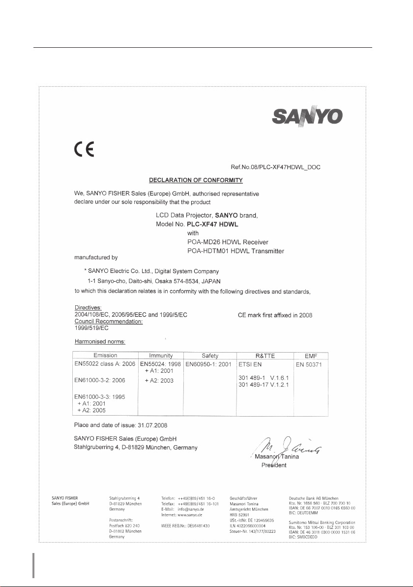
Compliance
Declaration of Conformity
10
Page 11
Preparation
Before use
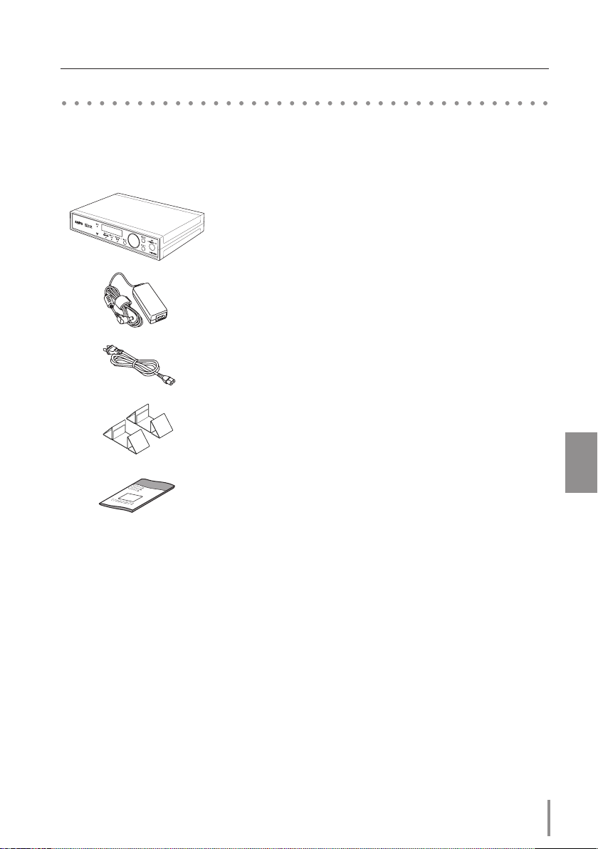
Package contents
The package contains following items. Check each item when unpacking the package. If
you have any of the following items missing, contact the sales dealer.
❑ HD DATA WIRELESS Transmitter 1 piece
❑ AC-DC Converter 1 piece
❑ AC Power Cord 1 piece
❑ Stand 2 pieces
❑ Owner's Manual 1 piece
Trademarks and Copyright
Each name of corporation or product in this Owner’s Manual is either a registered trademark or a
trademark of its respective corporation.
Notes
- The contents of this manual are subject to change without notice.
- We shall not be responsible for any damages caused by reliance on this manual.
- The word "projector" found in this manual means "projector provided with the HD DATA WIRELESS
Board" unless otherwise noted.
- The word "receiver" in this manual means "HD DATA WIRELESS Receiver Board: POA-MD26HDWL".
HD DATA WIRELESS TRANSMITTER BOX
OWNER'S MANUAL
English
11
Page 12
Preparation
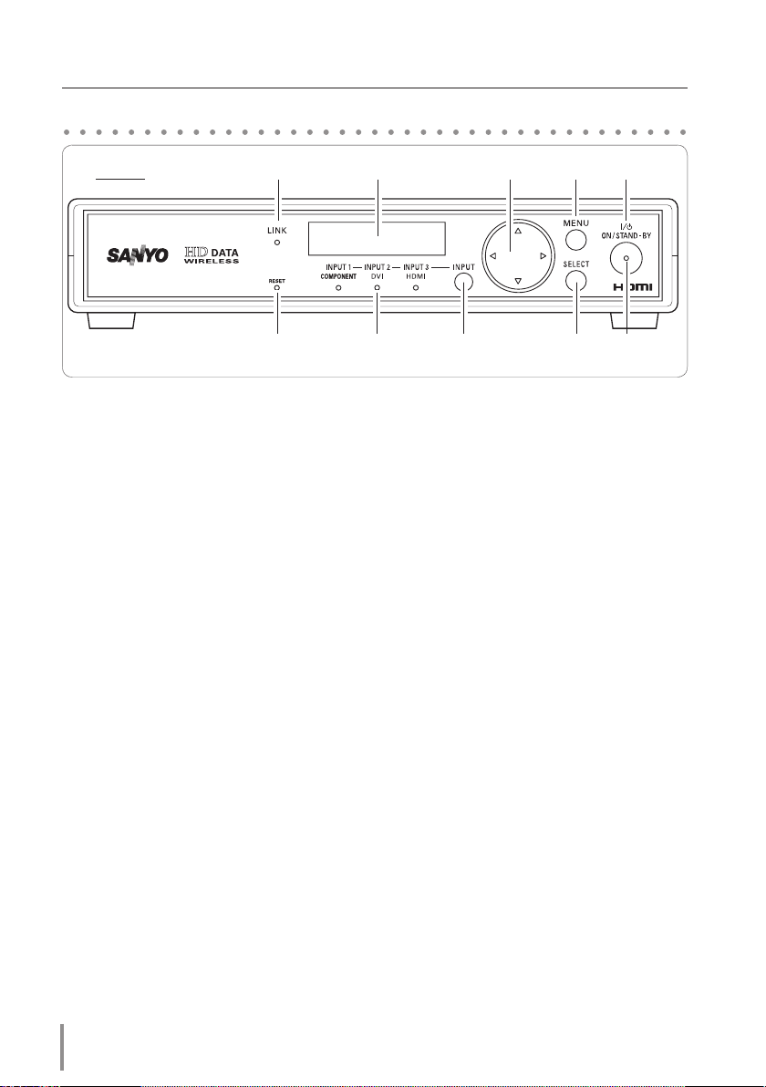
Part Names and Functions
Front
LINK INDICATOR
q
- When the wireless conguration
is set up correctly and the wireless
communication is established with
the wireless receiver at the single
mode, this indicator lights orange.
- This indicator lights orange during
operation in the broadcast mode.
q w e
y
u i ot!0
RESET BUTTON
y
A built-in micro processor which
controls this unit may occasionally
malfunction and need to be reset.
This can be done by pressing this
RESET button with a pen, which will
shut down and restart the unit. Do
not use the RESET function exces-
r
sively.
LCD DISPLAY
w
Display the selected menu. The back
light LED will be turned o when
INPUT INDICATORS
u
An indicator of the selected input
lights blue.
the transmitter is not operated for 3
minutes.
POINT
e
ed7 8
Select an item or adjust the value on
BUTTONS
INPUT BUTTON
i
Select an input source.
the menu on the display.
MENU BUTTON
r
Open or close the menu on the
SELECT BUTTON
o
Execute the selected menu.
display.
ON/STAND-BY BUTTON
t
POWER INDICATOR
!0
Turn the transmitter on or o. - Lights red when the transmitter is
in stand-by mode.
- Lights green during operation.
12
Page 13

Preparation
Rear
q w e
r t y
INPUT 1 COMPONENT
q
Connect component output signal
(Y-Pb/Cb-Pr/Cr) from video equipment to this terminal.
INPUT 2 DIGITAL (DVI-D)
w
Connect DVI digital output signal
from computer to this terminal.
INPUT 3 HDMI
e
Connect HDMI output signal from
video equipment to this terminal.
This input is only available in the
single mode.
This input cannot be selected in the
✐ -
broadcast mode.
- When selecting this input in the single
mode, the "Broadcast Mode" cannot
be selected in "Mode Select".
DC 16V
r
Connect the AC adapter (supplied).
SERIAL
t
- This terminal is used to service the
transmitter.
- If you control the transmitter by
computer, you must connect a serial cross cable (not supplied) from
your computer to this terminal.
VENTILATION SLOT
y
Do not cover the ventilation slot
during operation.
English
Note:
When you want to use the transmitter in the upright position, you
can use the supplied 2 stands. The antenna is provided near the
ventilation slot, so it is recommended to stand the transmitter as
shown in the figure for keeping the wireless communication in
good condition.
HD DATA WIRELESS TRANSMITTER BOX
OWNER'S MANUAL
13
Page 14

Installation
Connection to external equipment
Cables used for connection
BNC Cable (BNC x 3)
q
DVI Cable
w
HDMI Cable
e
Serial Control Cable
r
Cables are not supplied with this unit.
Unplug the power cords of both the
transmitter and external equipment
from the AC outlet before
connecting cables.
Component Output
BNC Cable
INPUT 1
COMPONENT
DVI Cable
Monitor Output Serial Control Output
INPUT 2
DVI-D
HDMI Output
HDMI Cable
INPUT 3
HDMI
SERIAL
Serial Control Cable
14
Page 15

DC16V 2.5A
Connecting the AC Power Cord
Installation
This transmitter uses nominal input
voltages of 100–120 V or 200–240 V AC.
- The AC outlet must be near this
equipment and must be easily
accessible.
- Use only the supplied AC
adaptor, and do not use any
other AC adaptor. Otherwise, a
malfunction may occur.
e
AC power cord
AC adaptor
q
Connect the AC adaptor with following
steps q to e.
When disconnecting, reverse the order.
✔Note:
- Be sure to turn off the transmitter, before
disconnecting the AC power cord.
- Unplug the AC power cord when the
transmitter is not in use. When the
transmitter is connected to an outlet with
the AC power cord, it is in stand-by mode
and consumes a little electric power.
w
English
Note on the AC Power Cord
AC power cord must meet the requirements of the country where you use the transmitter.
Confirm the AC plug type with the chart below and proper AC power cord must be used. If
the supplied AC power cord does not match your AC outlet, contact your sales dealer.
AC adapter side AC outlet side
For the U.S. and
Canada
To the AC outlet
(120 V AC)
For Continental
Europe
To the AC outlet
(200 - 240 V AC)
HD DATA WIRELESS TRANSMITTER BOX
For the U.K.
To the AC outlet
(200 - 240 V AC)
OWNER'S MANUAL
15
Page 16

Installation
Installing the Receiver into the Projector
Part Names and Functions
Receiver
LINK INDICATOR
q
When the wireless conguration is set
up correctly and the wireless communication is established with the transmitter, this indicator lights orange.
q w
Replacement of the Receiver Board
Insert the HD DATA WIRELESS Receiver
board. The cover of the board protrudes
from the cabinet of the projector.
We recommend that the HD DATA WIRELESS Receiver board is inserted into the
top slot for preventing influence from
the cables of other slots.
✔Note:
- In the event of replacement of interface
board, turn off the projector, press the
Main On/Off Switch to Off and unplug
the AC power cord from the AC outlet.
1 Remove 2 Screws from an interface
board or a slot cover.
2 Pull out the interface board. or a slot
cover.
3 Insert the HD DATA WIRELESS Receiver
board along Guide to fit Plug into
Socket.
4 Tighten 2 screws to secure the HD
DATA WIRELESS Receiver board.
Plug
POWER INDICATOR
w
When this receiver is selected in the
projector, this indicator lights green
during operation.
Slot Cover or
Interface Board
Guide
Screws
Socket
Screws
✐ 1(one) HD DATA WIRELESS Receiver Board is available in 1(one) projector.
16
Page 17

Basic Setting and Operation
Projector Operation
Turning on the Projector
1. Connect the projector’s AC power cord into an AC outlet and turn on the MAIN ON/OFF
Switch. The LAMP indicator lights red and the READY indicator lights green.
2. Press the ON/STAND-BY button on the side control or on the remote control. The LAMP
indicator dims red and the cooling fans start to operate. The preparation display appears
on the screen and the countdown starts.
3. After the countdown, the input source that was selected the last time and the Lamp
mode icon appear on the screen.
If the projector is locked with a PIN code, PIN code Input Dialog Box will appear. Enter the
PIN code.
Input Selection
1. Press the INPUT 1/2/3/4 buttons on the remote control or INPUT 1/2 or 3/4 buttons on
the side control to select the HD DATA Wireless Board. (You can also select it with Menu
operation, refer to the owner's manual of the projector.)
2. Check the status of the POWER indicator on the HD DATA Wireless Board. When the HD
DATA Wireless Board is selected correctly, the POWER indicator lights green.
English
Receiver
POWER Indicator
INPUT MENU
Input Menu icon
Move the pointer (red arrow) to the
input which the HD DATA Wireless
Board is inserted and press the
SELECT button.
HD DATA WIRELESS TRANSMITTER BOX
OWNER'S MANUAL
17
Page 18

Basic Setting and Operation
INPUT SIGNAL >>
[S] XGA 1
INPUT SIGNAL >>
[S] <none>
Hello
HD Data Wireless
INPUT SIGNAL >>
[S] XGA 1
INPUT SIGNAL >>
<none>
Link On
RF Freq. **.*MHz
Authentication
[Yes] NO
Authentication
Yes [NO]
Transmission
[OK] NG
Phase 1/2
INPUT SIGNAL >>
[S] <none>
Input Lock Key
[#]### OK
Input Lock Key
#[#]## OK
H Freq.
V Freq.
H Rez. ****
V Rez. ****
[YES] NO
Initialize
YES [NO]
Transmission
OK [NG]
H Position 2/2
INPUT SIGNAL >>
[S] XGA 1
Turning on the Transmitter
1. Complete peripheral connections before turning on the
transmitter.
2. Connect the AC power cord into an AC outlet. (see p.13) The
POWER indicator blinks red and then becomes red in stand-by
mode.
3. Pres s the ON/STAND-BY button. The PO WER indicator
becomes green and the message "Hello HD Data Wireless"
appears on the LCD display for 4 seconds and then the input
source that was selected the last time appears on the LCD
display.
4. When the wireless communication is established with the
receiver, the LINK indicator lights up.
5. If the transmitter is locked with the Key Lock function, release
Lock Key. Refer to the Key Lock function on pages 32 - 33.
✐ If the Lock Key is not entered for 3 minutes after "Input Lock Key"
appeared, the transmitter will be turned off automatically.
Turning off the transmitter
1. Pres s the ON/STAND-BY button. The POWER indicator
becomes red and the display will disappear.
2. Unplug the AC power cord from the AC outlet.
POWER indicator
after 4 seconds
18
Page 19

Input Source Selection
INPUT SIGNAL >>
[B] XGA 1
Authentication
Yes [NO]
ID Number
****-****
Failure
Image 2/6
Adjust
INPUT SIGNAL >>
[B] XGA 1
Image 2/6
Adjust
INPUT SIGNAL >>
[B] XGA 1
1. Choose either INPUT 1 (COMPONENT), INPUT 2 (DVI) or INPUT
3 (HDMI) by pressing the INPUT button.
Basic Setting and Operation
INPUT button
2. The Indicator of the selected input lights blue.
INPUT but tonINPUT indicators
✐ "INPUT 3 HDMI" cannot be selected in the Broadcast Mode.
How to Operate the Menu
1. Press the MENU button to show the LCD Display.
2. Press the Point
the SELECT button. A Sub Menu appears on the LCD Display.
3. Press the Point
the SELECT button.
✐ Press the point 7 button in a Sub Menu to return to a Main Menu..
4. Press the Point
5. To quit the Menu, press the MENU button again and Input
Source appears on the LCD Display.
buttons to select a Main Menu and press
de
buttons to select a Sub Menu and press
de
buttons to set up or adjust the item data.
7 8
INPUT 1
COMPONENT
INPUT 2
DVI
INPUT 3
HDMI
Point button
MENU button
English
SELECT button
Examples of LCD Display
Selected Mode
[B] . . . . . . in Broadcast Mode
[S] . . . . . . in Single Mode
Signal Information
Page Number Bracket [ ]
Menu Guide
de buttons are available.
Menu Guide
7 8 buttons are available.
HD DATA WIRELESS TRANSMITTER BOX
OWNER'S MANUAL
19
Page 20

Basic Setting and Operation
Menu Tree
TRANSMITTER
MAIN MENU SUB MENU
Single Mode
1/6
Setup
1/2 Authentication Yes/No
2/2 Initialize Yes/No
Broadcast Mode
1/6
Setup
1/1
Output Level
Select
1,2,3,4,5
2/6 Image Adjust 1/2 Contrast Setting UP/DOWN
2/2 Brightness Setting UP/DOWN
3/6 Information Link On / Link Off
H freq. / V freq.
H resol. / V resol.
4/6 ID Number ID Number
5/6 Key Lock Input Lock Key
v
OK
1/2 Key Lock ON/OFF
2/2 Change Lock Key
Change Lock Key
New Lock Key OK
6/6 Mode Select Single Mode
Broadcast Mode
v "Input Lock Key" is displayed when a lock key is not set.
PROJECTOR
HD DATA
WIRELESS
Mode select
Authentication Execute / Reset
OK
Single mode /
Broadcast mode
20
Input ID
Reception level
Reset Yes / No
Quit
Set / Cancel
Page 21

Flow of Installation Mode
TRANSMITTER PROJECTOR
Single Mode Operation
When using a pair of transmitter and receiver for the first time.
Basic Setting and Operation
Select "Single Mode" in
Step 1:
"Mode Select"..
Step 2: Execute "Authentication". Step 2:
Step 3: "Please wait ..." >>> "Success" Step 3:
When changing a pair of transmitter and receiver,
Execute "Initialize" to reset
Step 1:
the authentication.
Step 2: Execute "Authentication". Step 2:
Step 3: "Please wait ...">>> "Success" Step 3:
Step 1:
Step 1:
Broadcast Mode Operation
When using a transmitter and receivers in broadcast mode.
Select "Broadcast Mode" in
Step 1:
"Mode Select"..
Step 1:
Select "Single mode" in
"Mode select".
Select "Execute" in
"Authentication".
"Please wait ..." >>> Su ccess
icon
Select "Reset" in
"Authentication".
Select "Execute" in
"Authentication".
English
"Please wait ..." >>> Su ccess
icon
Select "Broadcast mode" in
"Mode select".
Input the same ID Number
Step 2: Check the "ID Number". Step 3:
Step 5: Adjust "Output Level". Step 4: Check "Reception Level".
of the transmitter into "Input
ID".
HD DATA WIRELESS TRANSMITTER BOX
OWNER'S MANUAL
21
Page 22

Authentication
[YES] NO
Authentication
YES [NO]
Authenti- 1/2
cation
Please wait...
SingleMode 1/6
Setup
Success
Failure
Single Mode Operation
Single
Mode
Mode 6/6
Select
Broadcast
Mode
INPUT SIGNAL >>
[S] XGA 1
6/6: Mode Select & 1/6: Single Mode Setup
TRANSMITTER
When using a pair of transmitter and receiver for the first time
Select the installation mode according to the situation in which the projector is installed.
When using in the single mode, it is necessary to perform the mutual authentication between the transmitter and the receiver. Setup them side by side as described below.
Main Menu 6/6: Mode Select
1. Press the MENU button to show the Menu. Press the Point de buttons to select Main
Menu 6/6: Mode Select and then press the SELECT button.
2. Press the Point
3. Input signal will be displayed [S] in the lower left-hand corner.
buttons to select the Single Mode.
7 8
Main Menu 1/6: Single Mode Setup
a Sub Menu 1/2: Authentication
1. Press the MENU button to show the Menu. Press the Point de button to select Main
Menu 1/6: Single Mode Setup and then press the SELECT button.
2. Press the Point
SELECT button.
3. Press the Point
button to perform the authentication.
4. The message "Please wait ..." will be displayed and the transmitter is waiting for the
response from the receiver.
5. Set up the authentication of the receiver.
6. If the authentication is completed, the message "Success" will be displayed for 5 seconds
and the LINK indicator lights orange.
If it is not completed within about 5 minutes, the message "Failure" will be displayed for
5 seconds.
buttons to select Sub Menu 1/2: Authentication and then press the
de
buttons to move the bracket to [YES] and then press the SELECT
7 8
✐ If you press Menu button during authentication, the authentication will be cancelled.
22
Page 23

Single Mode Operation
PROJECTOR
Mode select
1. Press the MENU button to display the On-Screen Menu. Use the Point 7 8 buttons to
move the red frame pointer to the HD DATA WIRELESS icon.
2. Use the Point
red frame pointer to the Mode Select
icon and then press the SELECT button
twice. A dialog box appears.
3. Use the Point
Single mode and then press the SELECT
button.
de buttons to move the
de buttons to select
Mode Select Menu
Authentication
1. Use the Point de buttons to move the red frame pointer to the Authentication icon
and then press the SELECT button. A dialog box appears.
2. Use the Point
Execute and then press the SELECT
button. The receiver starts to establish
communication with the transmitter.
The message "Please wait ..." will be
displayed until the establishment.
3. Set up the authentication of the
transmitter.
4. If the authentication is completed, the
Success icon will be displayed for 4
seconds.
If it is not completed within about
5 minutes, the Failure icon will be
displayed for 4 seconds. Please check
the settings of the transmitter or the
receiver.
de buttons to select
Authentication Menu
Success icon Failure icon
English
5. When the communication is established,
the LINK indicator lights orange.
✐ I f you press any butt on on the proj ector or the remote contr ol dur ing auth ent ica tio n, the
authentication will be cancelled.
HD DATA WIRELESS TRANSMITTER BOX
OWNER'S MANUAL
23
Page 24

Single Mode Operation
Authentication
[YES] NO
Authentication
YES [NO]
Authenti- 1/2
cation
Please wait...
SingleMode 1/6
Setup
Initialize 2/2 Initialize
[YES] NO
Success
Failure
SingleMode 1/6
Setup
TRANSMITTER
When changing a pair of transmitter and receiver
If you want to communicate with the other receiver, you should reset the current
authentication.
Main Menu 6/6: Mode Select
If not set to the Single Mode, set to the Single Mode. Refer to page 22.
Main Menu 1/6: Single Mode Setup
a Sub Menu 2/2: Initialize
1. Press the MENU button to show the Menu. Press the Point de button to select Main
Menu 1/6: Single Mode Setup and then press the SELECT button.
2. Press the Point
SELECT button.
3. Press the Point
button to perform the initialization.
buttons to select Sub Menu 2/2: Initialize and then press the
de
buttons to move the bracket to [YES] and then press the SELECT
7 8
Main Menu 1/6: Single Mode Setup
a Sub Menu 1/2: Authentication
Perform the Authentication again. Refer to page 22.
24
Page 25

Single Mode Operation
PROJECTOR
Mode select
If not set to the Single mode, set to the Single mode. Refer to page 23.
Authentication
1. Use the Point de buttons to move the red frame pointer to the Authentication icon
and then press the SELECT button. A dialog box appears.
2. Select
Reset and then press the SELECT
button. The authentication will be reset.
Authentication Menu
Authentication
Perform the Authentication again. Refer to page 23.
English
HD DATA WIRELESS TRANSMITTER BOX
OWNER'S MANUAL
25
Page 26

Broadcast Mode Operation
Single
Mode
Mode 6/6
Select
Broadcast
Mode
ID Number 4/6
ID Number
****-****
Authentication
Yes [NO]
Input Lock Key
#[#]## OK
H Freq.
V Freq.
H Rez. ****
V Rez. ****
Initialize
YES [NO]
Transmission
OK [NG]
H Position 2/2
INPUT SIGNAL >>
[S] XGA 1
Input Lock Key
#### [OK]
INPUT SIGNAL >>
[B] XGA 1
Select the installation mode according to the situation in which the projector is installed.
When using in the broadcast mode, it is necessary to set up the ID number into the receiver
which is conformed to that of the transmitter.
Setup them side by side as described below.
6/6: Mode Select & 4/6: ID Number
Main Menu 6/6: Mode Select
1. Press the MENU button to show the Menu. Press the Point de buttons to select Main
Menu 6/6: Mode Select and then press the SELECT button.
2. Press the Point
orange.
3. Input signal will be displayed [B] in the lower left-hand corner.
Main Menu 4/6: ID Number
1. Press the MENU button to show the Menu. Press the Point de buttons to select Main
Menu 4/6: ID Number and then press the SELECT button.
2. An eight-digit
the projector.
TRANSMITTER
buttons to select the Broadcast Mode. The LINK indicator lights
7 8
ID Number will be displayed. Note it and set up the same ID number in
3. Press the MENU button to exit this Menu.
✐ When selecting "INPUT 3 HDMI" in Single Mode, Broadcast Mode cannot be selected..
✐ ID Number characters : 0 to 9, A to F
26
Page 27

Broadcast Mode Operation
PROJECTOR
Mode select
1. Press the MENU button to display the On-Screen Menu. Use the Point 7 8 buttons to
move the red frame pointer to the HD DATA WIRELESS icon.
2. Use the Point
red frame pointer to the Mode Select
icon and then press the SELECT button
twice. A dialog box appears.
3. Use the Point
Broadcast mode and then press the
SELECT button.
de buttons to move the
Mode Select Menu
de buttons to select
Input ID
1. Before inputting the ID Number, check
the ID Number in the transmitter.
2. Use the Point
Input ID and then press the SELECT
button.
3. Input the ID Number as follows;
Select a number by pressing the Point
buttons. And then press the Point
de
button to fix the number and move
8
the pointer. If you fixed the incorrect
number, move the pointer to the
number you want to correct by pressing
the Point 7 button, and then select the
correct number by pressing the Point
buttons.
de
4. Repeat this step to complete entering an
eight-digit number.
5. After entering the eight-digit number,
move the pointer to "Set" by pressing
the Point 8 button. Press the Select
button to continue.
6. Confirmation box appears, select [Yes] to
confirm the ID Number.
buttons to select
de
Input ID Menu
English
✐ Once authenticated in Single mode, the ID Number of the transmitter which has been set in Single
mode will be displayed as a default. When switching from Single mode to Broadcast mode, change the
ID Number to the new one of the transmitter.
HD DATA WIRELESS TRANSMITTER BOX
OWNER'S MANUAL
27
Page 28

Output Level
5
Output Level
1
Output 1/1
Level Select
Broadcast 1/6
Mode Setup
Broadcast Mode Operation
TRANSMITTER
1/1: Output Level Select
Noise or interference may appear on images of some projectors when using in the
broadcast mode depending on whether the signal reception level of receiver is too high or
low. Try to adjust the output level of the transmitter to get the best reception condition for
all projectors.
1. Press the MENU button to show the Menu. Press the Point
Menu "1/6: Broadcast Mode Setup" Menu and then press the SELECT button.
buttons to select Main
de
2. Press the Point
press the SELECT button.
3. Press the Point
SELECT button to perform the adjustment.
1 . . . . . .minimum output level
5 . . . . . .maximum output level
buttons to select Sub Menu "1/1: Output Level Select" and then
de
buttons to select the Output Level (1 to 5) and then press the
7 8
28
Page 29

Broadcast Mode Operation
PROJECTOR
Reception Level
1. Press the MENU button to display the On-Screen Menu. Use the Point 7 8 buttons to
move the red frame pointer to the HD DATA WIRELESS icon.
2. Use the Point
red frame pointer to Reception level
icon and then press the SELECT button.
3. The Reception Level (0 to 7) display
appears.
0. . . . . . minimum reception level
7. . . . . . maximum reception level
4. If necessary, try to adjust the output
level of the transmitter.
5. When any button is pressed on the
side panel or the remote control, the
reception level disappears.
de buttons to move the
Reception Level Menu
Reception Level
Level 7
Level 5 (Level 5 to 7 = green)
Level 3 (Level 3 to 4 = yellow)
Level 1 (Level 1 to 2 = red)
English
Level 0 ( = white)
HD DATA WIRELESS TRANSMITTER BOX
OWNER'S MANUAL
29
Page 30

Input Lock Key
[#]### OK
Key Lock 5/6
Input Lock Key
#### [OK]
Key Lock 1/2
Input Lock Key
[#]### OK
Key Lock 5/6
Input Lock Key
#### [OK]
Key Lock 1/2
Key Lock
[ON] OFF
Key Lock
ON [OFF]
Key Lock 1/2
Input Lock Key
[#]### OK
Key Lock
Other Basic Operation
5/6: Key Lock
This function allows you to lock the key operation on the transmitter.
TRANSMITTER
To enter a new Lock Key
At first, set up a new Lock Key in the transmitter to operate Key Lock function.
✐ If a Lock Key is already set, this menu
1. Press the MENU button to show the Menu. Press the Point de buttons to select Main
Menu "5/6: Key Lock" and then press the SELECT button. "Input Lock Key [#]### OK"
will be displayed.
2. Use the Point
number and move to the next box.
3. Repeat this step to complete entering a four-digit number.
4. Press the Point
button.
1/2: Key Lock" will be displayed.
5. "
buttons to enter a number (0 ~ 9). Press the Point 8 button to fix the
ed
buttons to move the bracket to [OK] and then press the SELECT
7 8
"Input Lock Key [#]### OK"
will not be displayed.
To set Key Lock
1. While Sub Menu "1/2: Key Lock" is displayed, press the SELECT button. "Key Lock ON
[OFF]" will be displayed.
2. Move the bracket from [OFF] to [ON] by pressing the Point
the SELECT button.
2. "Key Lock" will be displayed.
3. While Key Lock is set to ON, when any button is pressed, "
be displayed.
buttons and then press
7 8
Input Lock Key #### OK" will
✐ Even when the AC power was shutdown, the key lock function is still available. If the transmitter is
locked with a lock key, "Input Lock Key" appears at turning on the transmitter. If the Lock Key is not
entered for 3 minutes after "Input Lock Key" appeared, the transmitter will be turned off automatically.
30
Page 31

Other Basic Operation
Input Lock Key
[#]### OK
Key Lock 5/6
Key Lock
[ON] OFF
Key Lock
ON [OFF]
Key Lock 1/2
Input Lock Key
#### [OK]
Input Lock Key
[#]### OK
Key Lock
New Lock Key
[#]### OK
Change Lock Key
[#]### OK
Change 2/2
Lock Key
Input Lock Key
[#]### OK
Key Lock 5/6
Key Lock 5/6
Input Lock Key
#### [OK]
Key Lock 1/2
New Lock Key
[#]### OK
Change Lock Key
[#]### OK
Change 2/2
Lock Key
Key Lock
[ON] OFF
Key Lock
ON [OFF]
Key Lock 1/2
Input Lock Key
[#]### OK
Key Lock
TRANSMITTER
To change Lock Key
1. Press the MENU button to show the Menu. Press the Point de buttons to select Main
Menu "5/6: Key Lock" and then press the SELECT button.
2. Press the Point
buttons to select Sub Menu "2/2: Change Lock Key" and then press
de
the SELECT button.
3. Enter the current four-digit number. Use the Point
buttons to enter a number. Press
ed
the Point 8 button to fix the number and move to the next box.
4. Press the Point
buttons to move the bracket to [OK] and then press the SELECT
7 8
button.
5. "New Lock Key" will be displayed. Enter a new four-digit number.
6. Press the Point
buttons to move the frame to [OK] and then press the SELECT
7 8
button.
To release Lock Key
1. Press a button on the transmitter. "Input Lock Key" will be displayed.
2. Enter the current four-digit number, the Lock Key will be released and you can operate
the transmitter.
English
Menu Tree of Key Lock
HD DATA WIRELESS TRANSMITTER BOX
OWNER'S MANUAL
31
Page 32

Brightness 2/2
Setting
Contrast 1/2
Setting
Image 2/6
Adjust
Brightness
-32
Contrast
+32
Link Off
RF Freq. ****MHz
Link On
RF Freq. ****MHz
Information 3/6
or
H Freq. ****
V Freq. ****
H Resol. ****
V Resol. ****
Other Basic Operation
2/6: Image Adjust
You can adjust contrast and brightness of the output signal from the transmitter.
1. Press the MENU button to show the Menu. Press the Point de buttons to select Main
Menu "2/6: Image Adjust" and then press the SELECT button.
TRANSMITTER
1/2: Contrast Setting
After the step 1;
2. Press the Point
the SELECT button.
3. Press the Point
buttons to select Sub Menu "1/2: Contrast Setting" and then press
de
buttons to adjust the contrast (-32 to +32).
7 8
2/2: Brightness Setting
After the step 1;
2. Press the Point
press the SELECT button.
3. Press the Point
buttons to select Sub Menu "2/2: Brightness Setting" and then
de
buttons to adjust the brightness (-32 to +32).
7 8
3/6: Information
Information display can be used to confirm the current output signal from the transmitter.
1. Press the MENU button to show the Menu. Press the Point
Menu "3/6 Information" and then press the SELECT button.
2. The information "
and "H/V Resolution" will be displayed periodically.
32
buttons to select Main
de
Link On / RF Frequency", "Link Off RF Frequency", "H/V Frequency"
Page 33

Other Basic Operation
Reset Function of the projector
Reset
1. Press the MENU button to display the
On-Screen Menu. Use the Point 7 8
buttons to move the red frame pointer
to the HD DATA WIRELESS icon.
2. Use the Point
Reset and the “Return to Wireless
factory default?” appears. Select [Yes] to
continue.
3. Another confirmation dialog box
appears, select [Yes] to reset the Wireless
setting of Mode select, Input ID and
Authentication.
de buttons to select
PROJECTOR
Reset Menu
English
HD DATA WIRELESS TRANSMITTER BOX
OWNER'S MANUAL
33
Page 34

Maintenance and Care
Cleaning the cabinet
Turn off the transmitter and unplug the AC power cord from the AC outlet before cleaning.
Gently wipe the transmitter body with a soft dry cleaning cloth. When the cabinet is heavily
soiled, use a small amount of mild detergent and finish with a soft dry cleaning cloth. Avoid
using an excessive amount of cleaner. Abrasive cleaners, solvents, or other harsh chemicals
might scratch the surface of the cabinet.
Indicators
When the transmitter detects an abnormal condition, it is automatically shut down to
protect the inside of the transmitter and three INPUT indicators and LINK indicator start
blinking. In this case, unplug the AC power cord and reconnect it, and then turn the
transmitter on once again to verify operation. If the transmitter cannot be turned on,
unplug the AC power cord and contact the service station.
34
Page 35

Appendix
Troubleshooting
Before calling your dealer or service center for assistance, check the items below once again.
- Make sure you have properly connected the transmitter to peripheral equipment.
- Make sure all equipment is connected to the AC outlet and the power is turned on.
Problem Solutions
No power --Plug the AC power cord into the AC outlet.
Check the connection of the AC adaptor and try to
re-connect the AC adaptor.
-
No image
Poor (noisy) Image
Block-noise of Images
Some Indicators are blinking.
Buttons do not work. - Unlock the key lock function.
Key Lock Number is required at
start-up.
Unable to select INPUT 3(HDMI) -
Unable to select the secondary
HD DATA WIRELESS Receiver
Board.
Check the LINK indicator.
-
Check the authentication in the single mode.
-
Check both ID numbers in the transmitter and the
projectors in the broadcast mode.
-
Check the compatible signals of the transmitter. (see
p.38)
-
Check the reception level of the projectors.
-
Try to increase the output level in the broadcast
mode.
-
Make sure there is no obstruction between the
transmitter and the projector.
-
Try to move the transmitter or the projector.
Maximum operation range is within about 30 m.
--Try to adjust the output level in the broadcast
mode.
Try to move the transmitter or the projector.
- When the transmitter detects an abnormal
condition, three INPUT indicators and LINK indicator
blinks. In this case, unplug the AC power cord and
reconnect it, and then turn the transmitter on once
again to verify operation. If the transmitter cannot
be turned on, unplug the AC power cord and
contact the service station.
-
The key lock function is being set. Enter the 4-digit
number you have set.
When using the broadcast mode, HDMI cannot be
selected.
-
1(one) HD DATA WIRELESS Receiver Board is
available in 1(one) projector. When using multiple
HD DATA WIRELESS Receiver Boards, only a slot with
the smallest number is available for use.
English
HD DATA WIRELESS TRANSMITTER BOX
OWNER'S MANUAL
35
Page 36

Appendix
Specifications
Interface
Component Input Jacks BNC Type x 3
Computer Digital Input Jack DVI-D Terminal x 1
HDMI Input Jack HDMI Terminal x 1
DC IN Jack DC 16 V (AC Adaptor)
Power
Voltage 100 - 120 V or 200 - 240V, 50/60 Hz
Power Consumption
Operating Environment
Operating Temperature 41ºF - 95ºF (5ºC - 35ºC)
Storage Temperature 14ºF - 140ºF (-10ºC - 60ºC)
Mechanical Information
Dimensions ( W x H x D ) 10.63" x 1.97" x 8.66" (270 x 50 x 220 mm)
Net Weight 2.87 lbs (1.3 kg)
Wireless Information
Interface IEEE802.11a/n
Communication Mode AdHoc
Wireless Frequency
Modulation Form IEEE802.11a OFDM
Security 256bit AES
Service area
DC 16V 1.0A
11.8 [W] at normal, 2.43 [W] at stand-by mode
US 5.18, 5.20, 5.22, 5.745, 5.765, 5.785, 5.805, 5.825 GHz
EU 5.18, 5.20, 5.22 GHz
about 98' (30 m) (line-of-sight without disturbance)
Differs according to the operating environment.
✐ The specifications are subject to change without notice.
36
Page 37

Compliance
Countries and Standards
Appendix
JAPAN: VCCI Class A, TELEC (Wireless)
USA: FCC Part15 Subpart C (Wireless)
FCC Part15 Subpart C, Class A
Canada: IC RSS-210 (Wireless), IC ICES-003 Class A
Europe: R&TTE, EMC, LVD
HD DATA WIRELESS TRANSMITTER BOX
OWNER'S MANUAL
English
37
Page 38

Appendix
Compatible Signals Specifications
TERMINAL SIGNAL RESOLUTION
INPUT 1 : COMPONENT 480p 31.47 59.88 480p
INPUT 3 : HDMI 575p 31.25 50.00 575p
720p - 50 37.50 50.00 720p
720p - 60 45.00 60.00 720p
1080i - 50 28.125 50.00 1080i
1080i - 60 33.75 60.00 1080i
INPUT 2 : DVI-D VGA 1 640 x 480 31.47 59.94 VGA 1
SVGA 2 800 x 600 37.88 60.32 SVGA 2
XGA 1 1024 x 768 43.363 60.00 XGA 1
WXGA 6 1280 x 768 47.776 59.87 WXGA 6
WXGA 10 1280 x 800 41.20 50.00 WXGA 10
H-Freq.
[kHz]
V-Freq.
[Hz]
LCD
DISPLAY
38
Page 39

1
9
17
2
10
18
3
11
19
4
12
20
5
13
21
6
14
22
7
15
23
8
16
24
Configurations of Terminals
1 3 5 7 9
11 13 15 17 19
1816141210
8642
INPUT 2 : DIGITAL DVI-D (DVI 24 Pin)
Appendix
T.M.D.S. Data2–
1
T.M.D.S. Data2+
2
T.M.D.S. Data2 Shield
3
No Connect
4
No Connect
5
DDC Clock
6
DDC Data
7
No Connect
8
T.M.D.S. Data1–
9
T.M.D.S. Data1+
10
T.M.D.S. Data1 Shield
11
No Connect
12
No Connect
13
+5V Power
14
Ground (for +5V)
15
Hot Plug Detect
16
INPUT 3 : HDMI (19 Pin Type A)
1
2
3
4
5
6
7
8
9
10
SERIAL CONTROL PORT (Mini D-sub 9 pin)
1
2
3
4
5
6
7
8
9
TMDS Data 2+ Input
Ground (TMDS Data 2)
TMDS Data 2- Input
TMDS Data 1+ Input
Ground (TMDS Data 1)
TMDS Data 1- Input
TMDS Data 0+ Input
Ground (TMDS Data 0)
TMDS Data 0- Input
TMDS Clock+ Input
Serial
No Connect
R X D
T X D
No Connect
SG
No Connect
RTS
CTS
No Connect
HD DATA WIRELESS TRANSMITTER BOX
T.M.D.S. Data0–
17
T.M.D.S. Data0+
18
T.M.D.S. Data0 Shield
19
No Connect
20
No Connect
21
T.M.D.S. Clock Shield
22
T.M.D.S. Clock+
23
T.M.D.S. Clock–
24
11
Ground (TMDS Clock)
12
TMDS Clock- Input
13
No Connect
14
No Connect
15
SCL
16
SDA
17
Ground (DDC/CEC)
18
+5V Power
19
Plug insert detection
OWNER'S MANUAL
English
39
Page 40

OWNER'S MANUAL POA-HDTM01
1AA6P1P5524-- (IFFZ)
SANYO Electric Co., Ltd.
 Loading...