

Page 1
FILE NO.
SERVICE MANUAL
Original Version
Multimedia Projector
MODEL NO.
Chassis No. ME4-Z300000
NOTE: Match the Chassis No. on the rating
sheet on the cabinet with the Chassis
No. in the Service Manual.
PLV-Z3000
U.S.A., Canada,Europe,
U.K. Asia, Africa
If the Original Version Service
Manual Chassis No. does not
match the unites, additional Service
Literature is required. You must refer
to “Notices” to the Original Service
Manual prior to servicing the unit.
www.electronicsrepair.net
PRODUCT CODE :
PLV-Z3000 ME4A
PLV-Z3000 PE4A
PLV-Z3000 PE4C
1 122 447 00
1 122 448 00
1 122 448 02
U.S.A., Canada
Europe, Asia, Africa
U.K.
REFERENCE NO.
SM5111017-
00
Page 2

■ Contents
SERVICE MANUAL ................................................................................. 1
Contents .................................................................................................. 2
Safety Instructions ............................................................................... 3
Safety Precautions ............................................................................ 3
Product Safety Notice ..................................................................... 3
Service Personnel Warning ........................................................... 3
Specifications ......................................................................................... 4
Circuit Protections ................................................................................ 5
Fuse........................................................................................................ 5
Lamp cover switch ........................................................................... 6
Thermal switch .................................................................................. 6
Warning temperature and power failure protection ........... 6
Maintenance and Cleaning ............................................................... 7
Cleaning the Air Filter ...................................................................11
Resetting the Filter Counter ....................................................... 12
Lamp Replacement ............................................................................13
Lamp Replacement Counter ......................................................14
How to check Lamp Used Time .................................................15
Service port Notice ............................................................................16
Mechanical Disassembly..................................................................17
Optical Parts Disassembly ...............................................................34
Optical parts location and direction ........................................40
Adjustments .........................................................................................44
Adjustments after Parts Replacement ....................................44
Optical Adjustments .........................................................................45
Contrast adjustment......................................................................45
Electrical Adjustments ......................................................................47
Service Adjustment Menu Operation .....................................47
Circuit Adjustments .......................................................................48
Test Points and Locations ............................................................52
Service Adjustment Data Table .................................................53
Chassis Block Diagram ...................................................................... 74
Chassis over view ............................................................................74
Video signal processing circuit ..................................................75
System control .................................................................................76
Fan control circuit ...........................................................................78
Power supply & protection circuit ............................................80
Motor driving circuit ......................................................................82
Troubleshooting .................................................................................85
Indicators and Projector Condition ..........................................85
No Power ...........................................................................................86
No Picture .......................................................................................... 88
Control Port Functions .....................................................................90
Scaler I/O Port Functions (PW190) ...........................................90
Electrical Parts List .............................................................................92
Electrical Parts Location ...............................................................93
Electrical Parts List .......................................................................... 94
Mechanical Parts List ...................................................................... 112
Cabinet Parts Location ............................................................... 112
Optical Parts Location ................................................................ 114
Mechanical Parts List .................................................................. 118
Diagrams & Drawings ...................................................................... A1
Parts description and reading in schematic diagram .......... A2
Schematic Diagrams ........................................................................ A3
Printed Wiring Board Diagrams .................................................... A9
Pin description of diode, transistor and IC .............................A13
Note on Soldering ...........................................................................A14
- 2 -
Page 3
■ Safety Instructions
SAFETY PRECAUTIONS
WARNING:
The chassis of this projector is isolated (COLD) from AC line by using the converter transformer. Primary side of the converter and lamp power supply unit circuit is connected to the AC line and it is hot, which hot circuit is identified with the
line ( ) in the schematic diagram. For continued product safety and protection of personnel injury, servicing
should be made with qualified personnel.
The following precautions must be observed.
1: An isolation transformer should be connected in the
power line between the projector and the AC line
before any service is performed on the projector.
2: Comply with all caution and safety-related notes pro-
vided on the cabinet back, cabinet bottom, inside the
cabinet or on the chassis.
3: When replacing a chassis in the cabinet, always be
certain that all the protective devices are installed
properly, such as, control knobs, adjustment covers or
shields, barriers, etc.
DO NOT OPERATE THIS PROJECTOR WITHOUT THE PROTE
CTIVE SHIELD IN POSITION AND PROPERLY SECURED.
4: Before replacing the cabinet cover, thoroughly inspect
the inside of the cabinet to see that no stray parts or
tools have been left inside.
Before returning any projector to the customer, the service personnel must be sure it is completely safe to operate without danger of electric shock.
PRODUCT SAFETY NOTICE
Product safety should be considered when a component replacement is made in any area of the projector. Components
indicated by mark in the parts list and the schematic diagram designate components in which safety can be of spe-
cial significance. It is, therefore, particularly recommended that the replacement of there parts must be made by exactly
the same parts.
SERVICE PERSONNEL WARNING
Eye damage may result from directly viewing the light produced by the Lamp used in this equipment. Always turn off
Lamp before opening cover. The Ultraviolet radiation eye protection required during this servicing.
Never turn the power on without the lamp to avoid electric-shock or damage of the devices since the stabilizer gener-
ates high voltages(15kV - 20kV) at its starts.
Since the lamp is very high temperature during units operation replacement of the lamp should be done at least 45
minutes after the power has been turned off, to allow the lamp cool-off.
- 3 -
Page 4

■ Specifications
Technical Specifications
Projector Type Multimedia Projector
Dimensions
Net Weight 16.5 lbs (7.5 kg
LCD Panel System
Panel Resolution 1920 x 1080 dots
Number of Pixels 6,220,800 (1920 x 1080 x 3 panels)
Color System PAL, SECAM, NTSC, NTSC4.43, PAL-M, and PAL-N
High Definition TV Signal 480i, 480p, 575i, 575p, 720p, 1080i, and 1080p
Scanning Frequency
Projection Image size (Diagonal) Adjustable from 40” to 300”
Projection Lens F 2.0 – 3.05 lens with f 22.6 – 45.3 mm with manual zoom and focus
Throw Distance 3.9’ – 60.4’ (1.2 m – 18.4 m)
Projection Lamp 165 W
Video Input Jacks
Computer Input Terminal mini D-sub 15 pin x 1
HDMI Input Terminals HDMI terminal 19 pin x 2
Service Port Connector mini Din 8 pin x 1
Feet Adjustment 0˚ to 6.5˚
Voltage and AC 100 – 120 V (2.9 A Max. Ampere), 50/60 Hz
(W x H x D)
15.75” x 5.75” x 13.62” (400,0 mm x 146.0 mm x 346.0 mm)
)
0.74” wide TFT Active Matrix type, 3 panels
H-sync. 15 kHz – 80 kHz, V-sync. 50 Hz – 100 Hz
RCA Type x 1 (Video), RCA Type x 3 (Y, Pb/Cb, Pr/Cr) x 2 and Mini DIN 4 pin x 1 (S-video)
(not including raised portions)
(The U.S.A. and Canada)
Power Consumption AC 200 – 240 V (1.5 A Max. Ampere), 50/60 Hz
Operating Temperature 41˚F – 95˚F (5˚C – 35˚C)
Storage Temperature
Remote Control
● The specifications are subject to change without notice.
● LCD panels are manufactured to the highest possible standards. Even though 99.99% of the pixels are effective, a tiny fraction
of the pixels (0.01% or less) may be ineffective by the characteristics of the LCD panels.
14˚F – 140˚F (-10˚C – 60˚C)
Power Source : AA or LR6 1.5 V ALKALINE Type x 2
Operating Range : 16.4’ (5 m)/±30˚
Dimensions : 2.13” x 1.04” x 6.81” (54 mm x 26.3 mm x 173mm)
Net Weight : 3.4 oz (95.5 g) (not including batteries)
(Continental Europe and The U.K.)
- 4 -
Page 5
■ Circuit Protections
This projector provides the following circuit protections to operate in safety. If the abnormality occurs inside the
projector, it will automatically turn off by operating one of the following protection circuits.
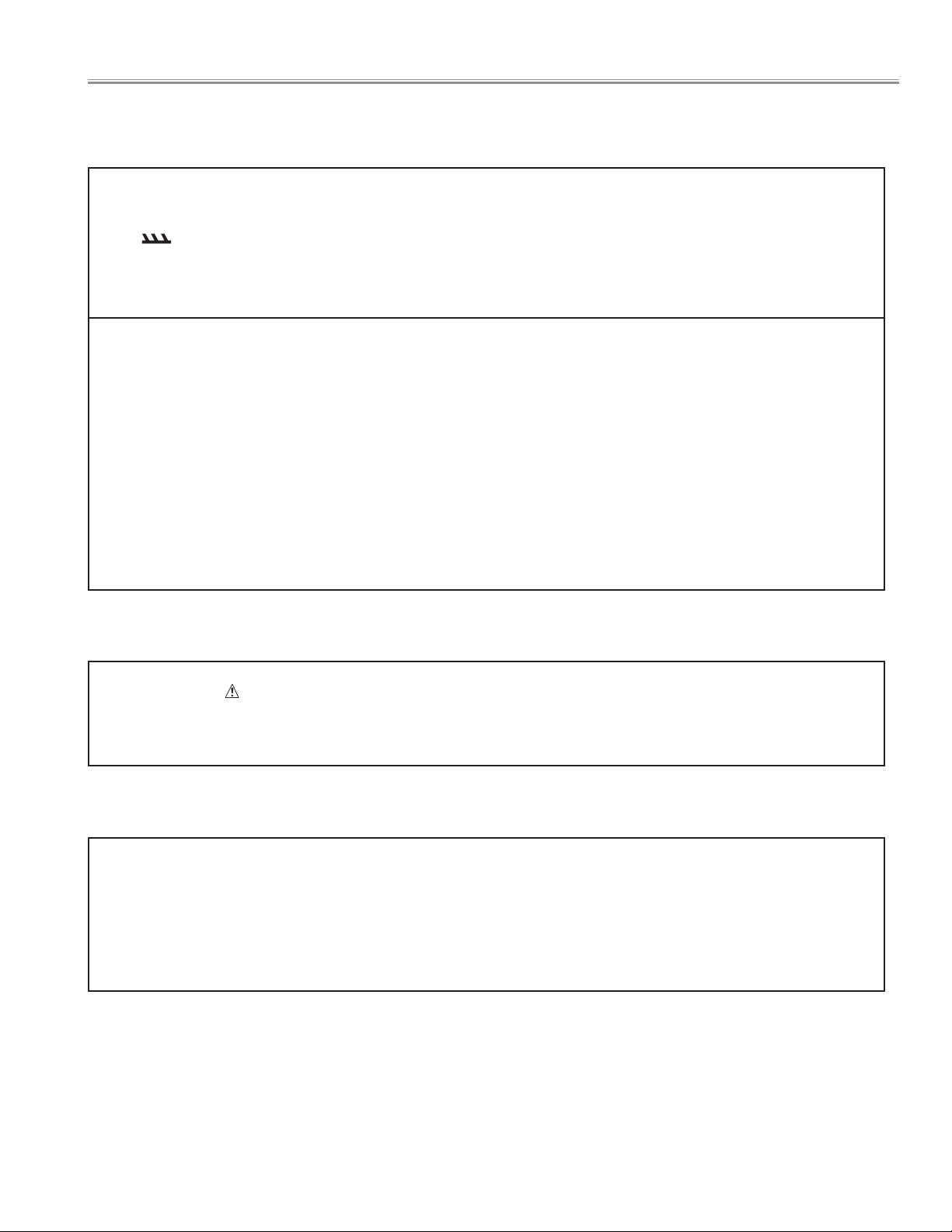
● Fuse
A fuse(F601) is located inside of the projector. When the
POWER indicator is not lightning, the fuse may be opened.
Check the fuse as following steps.
The fuse should be used with the following type;
Fuse Part No. : 323 024 3206
TYPE T5.0AH 250V FUSE
LITTEL FUSE INC. TYPE 215005
How to replace the fuse
1. Remove the cabinet top following to "Mechanical
Disassemblies".
2. Remove the fuse from fuse holder on the Filter Board.
To install the fuse, take reversed step in the above.
● Thermal switch
There is the thermal switch (SW902) inside of the projector
to prevent the internal temperature rising abnormally.
When the internal temperature reaches near 100°C, the
thermal switch cuts off the drive signal to the lamp circuit
automatically. The thermal switch is not reset to normal
automatically, even if the internal temperature becomes
normal. Reset the thermal switch following procedure.
Check the resistance between terminals of thermal switch
by using a tester. If it has high impedance, thermal switch
may be open.
Fuse (F601)
Thermal switch (SW902)
How to reset the thermal switch
1. Remove the Lamp cover foll o wing to "Mechanical
Disassemblies".
2. Press the reset button on the thermal switch with a
sharp-pointed tool.
CAUTION:
Before press the reset button, make sure that the AC cord
must be disconnected from the AC outlet.
- 5 -
Press
The switch(SW902) is
in the hole of cabinet.
Page 6
Circuit Protection
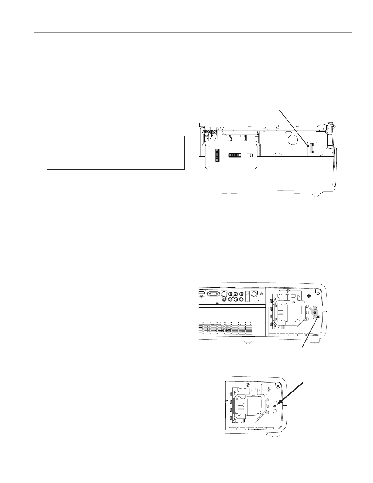
● Lamp cover switch
The lamp cover switch (SW8803) cuts off the drive signal
to the lamp circuit when the lamp cover is removed or not
closed completely.
After opening the lamp cover for replacing the lamp unit,
place the lamp cover correctly otherwise the projector can
not turn on.
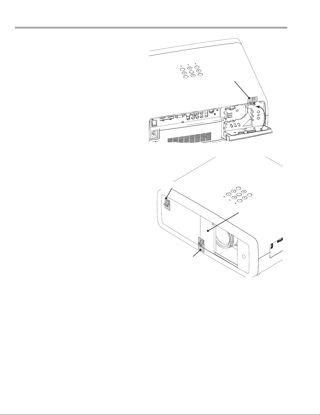
● Door switches for automatic slide shutter
The projector provides 2 door switches against an accident
of the automatic slide shutter.
The door swi tch-A(SW8801) turn s ON when the slide
shutter is opened.
The door switch-B( SW8811 ) turns ON when t he slide
shutter is closed.
If the slide shutter stops half-open after turning on, the
POWER indicator will blink orange and the projector goes
to stand-by mode after cooling. In this case, press the
POWER ON/STAND-BY button again.
If the slide shutter is closed during operation, the projector
is automatically turned off for safety.
In this case, be sure to check the position of the slide
shutter. Af t e r ope n i n g or clos i n g th e slid e shut te r
manually, press the POWER ON/STAND-BY button and the
projector turns on.
Lamp cover switch
Door switch-A
Slide shutter
Door switch-B
● Warning temperature and power failure protection
The projector will be automatically turned off when the internal temperature of the projector is abnormally high, or the
cooling fans stop spinning, or the power supplies in the projector are failed.
- If the WARNING indicator is flashing, it may detect the abnormal temperature inside the projector. Check the following
possible causes and wait until the WARNING indicator stops flashing, and then try to turn on the projector.
- If the WARNING indicator lights red, it may defect the cooling fans or power supply circuits. Check fans operation and
power supply lines referring to the chapter “Power supply & protection circuit” in the power Supply Lines section.
Possible causes
- Air filters are clogged with dust particles. Remove dust from the air filters.
- Ventilation slots of the projector are blocked. In such an event, reposition the projector so that ventilation slots are not
obstructed.
- Check if projector is used at higher temperature place (Normal operating temperature is 5 to 35˚C or 41 to 95˚F)
- 6 -
Page 7

■ Maintenance and Cleaning
After long periods of use, dust and other particles will accumulate on the LCD panel, prism, mirror, polarized glass,
lens, etc., causing the picture to darken or color to blur. If this occurs, clean the inside of optical unit.
Remove dust and other particles using air spray. If dirt cannot be removed by air spray, disassemble and clean
the optical unit.
● Cleaning with air spray
1. Remove the cabinet top following to "Mechanical Disassemblies".
2. Clean up the LCD panel and polarized glass by using the air spray from the cabinet top opening.
Caution:
Use only the supplied air blower and nozzle to keep the projector from being out of oder or damaged. We could not guarantee
the malfunction or breakage caused by other tools.
Be vary careful not to damage optical parts with the nozzle tip. Never use any kind of cleanser on the unit. Also, never use
abrasive materials on the unit as this may cause irreparable damage.
● Disassembly Cleaning
Disassembly cleaning method should only be performed when the unit is considerable dirty and cannot be sufficiently
cleaned by air spraying alone.
Be sure to readjust the optical system after performing disassembly cleaning.
1. Remove the cabinet top and main units following to "Mechanical Disassemblies".
2. Remove the optical base top following to"Optical Unit Disassemblies". If the LCD panel needs cleaning, remove the LCD
panel unit following to "LCD panel/Prism ass'y replacement".
3. Clean the optical parts with a soft cloth. Clean extremely dirty areas using a cloth moistened with alcohol.
Caution:
The surface of the optical components consists of multiple dielectric layers with varying degrees of refraction.
Never use organic solvents (thinner, etc.) or any kind of cleanser on these components.
Since the LCD panel is equipped with an electronic circuit, never use any liquids (water, etc.) to clean the unit. Use of
liquid may cause the unit to malfunction.
- 7 -
Page 8
Maintenance and Cleaning
Cleaning the RGB panels
Blemishes such as dust and dirt on the internal optical components of the projector tend to degrade the brightness of
the screen and are likely to appear as a shadow on the screen, which can lead to deterioration of image quality.
This projector is equipped with the RGB panel cleaning holes on the bottom for cleaning of the internal parts (such
as optical components) of the projector. When you use the projector for a lengthy period of time or a shadow of dust
appears on the projected screen, clean the inside of the projector.
Using the supplied air blower and with the Cleaning function in the Setting Menu, you can remove the dusts from the
projector.
✔Note:
• Dust might not be removed completely with these steps. In that case, contact the dealer where you purchased the
projector or service center.
CAUTION IN USING THE AIR BLOWER AND THE NOZZLE
● Turn the projector over when using the blower.
● Use only the supplied air blower and nozzle to keep the projector from being out of oder or damaged. We
CAUTION
● Never use a commercially available compressed air duster. It causes the interior of the projector to
● Put the projector on a soft cloth to prevent scratching the surface.
PROHIBITED
● Open the hole cover only when you clean the inside of the projector.
● Do not look into the holes. A strong light could damage your eyes. (Do not look into the Air intake vent and
● Use the blower and nozzle only to clean the projector. Do not attempt to use them for other purposes. Do
● Do not attempt to pull the nozzle out of the blower. If the nozzle happened to be pulled out, put it back
●
In the unlikely event that something goes wrong (smoke, a strange sound, an abnormal odor, and such) while you are
cleaning, turn off and unplug the projector immediately, then call the dealer where you purchased the projector or
service center.
could not guarantee the malfunction or breakage caused by other tools.
malfunction with release of cold liquid propellant.
Exhaust vent, either.)
not use the blower and nozzle against persons (particularly to eyes, mouth or ear, and so on). Be especially
careful to ensure that children do not put the blower and nozzle into their mouth and swallow them.
into the blower immediately.
Do not use the blower supplied with this projector (model: Z700) to clean the other models: Z4, Z3, and
Z1X.
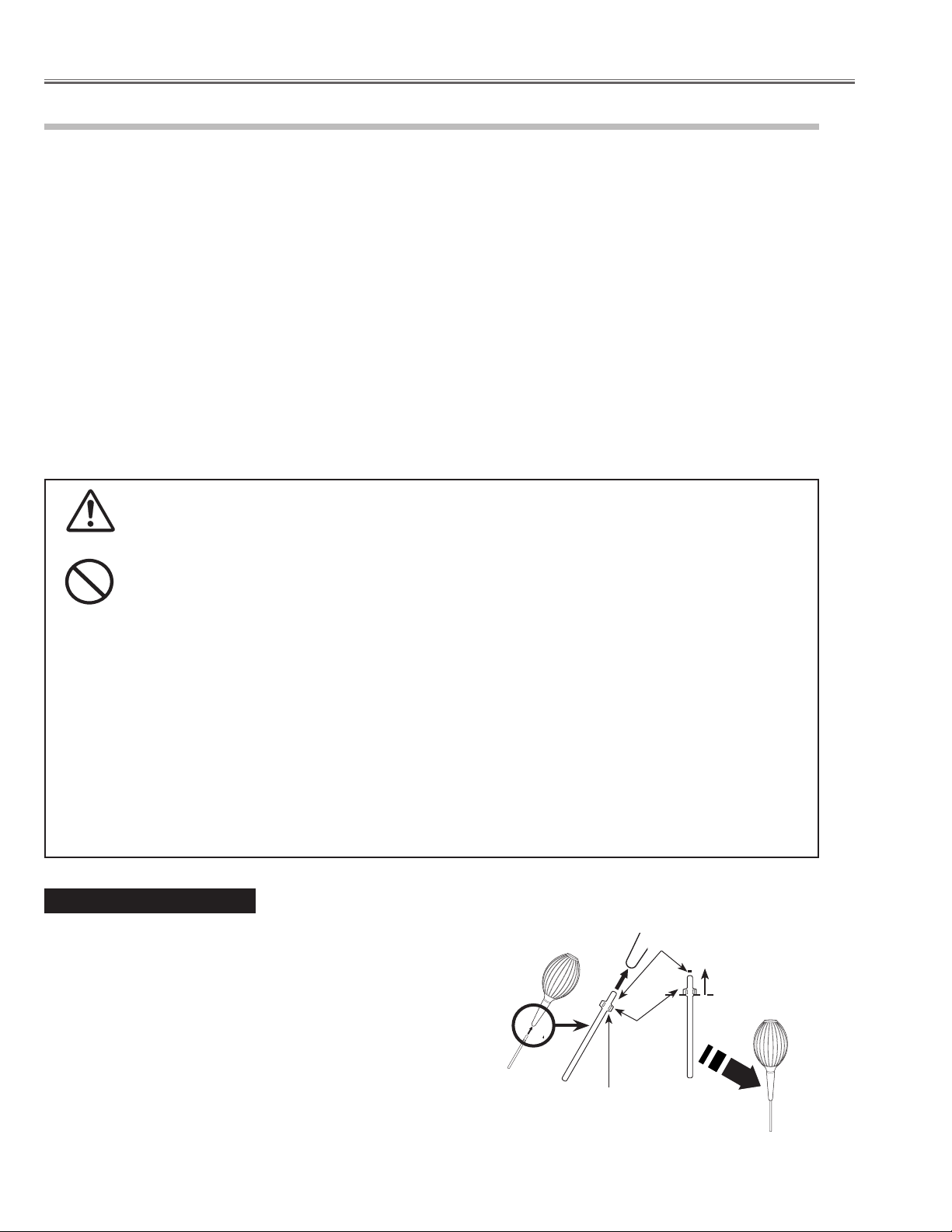
If the nozzle is pulled out ....
The nozzle has the stopper. Put the stopper-side of the nozzle into the
blower. Put the nozzle firmly into the blower until the stopper becomes
invisible.
When putting the nozzle into the blower, hold near the stopper so that
it will not break.
Make sure not to attempt to pull the nozzle out of the blower.
- 8 -
Put this end of the
nozzle into the
blower.
Put the nozzle in
until the stopper
becomes invisible.
Stopper
Hold near the stopper
of the nozzle.
Page 9
B
R
G
B
R
G
Maintenance and Cleaning
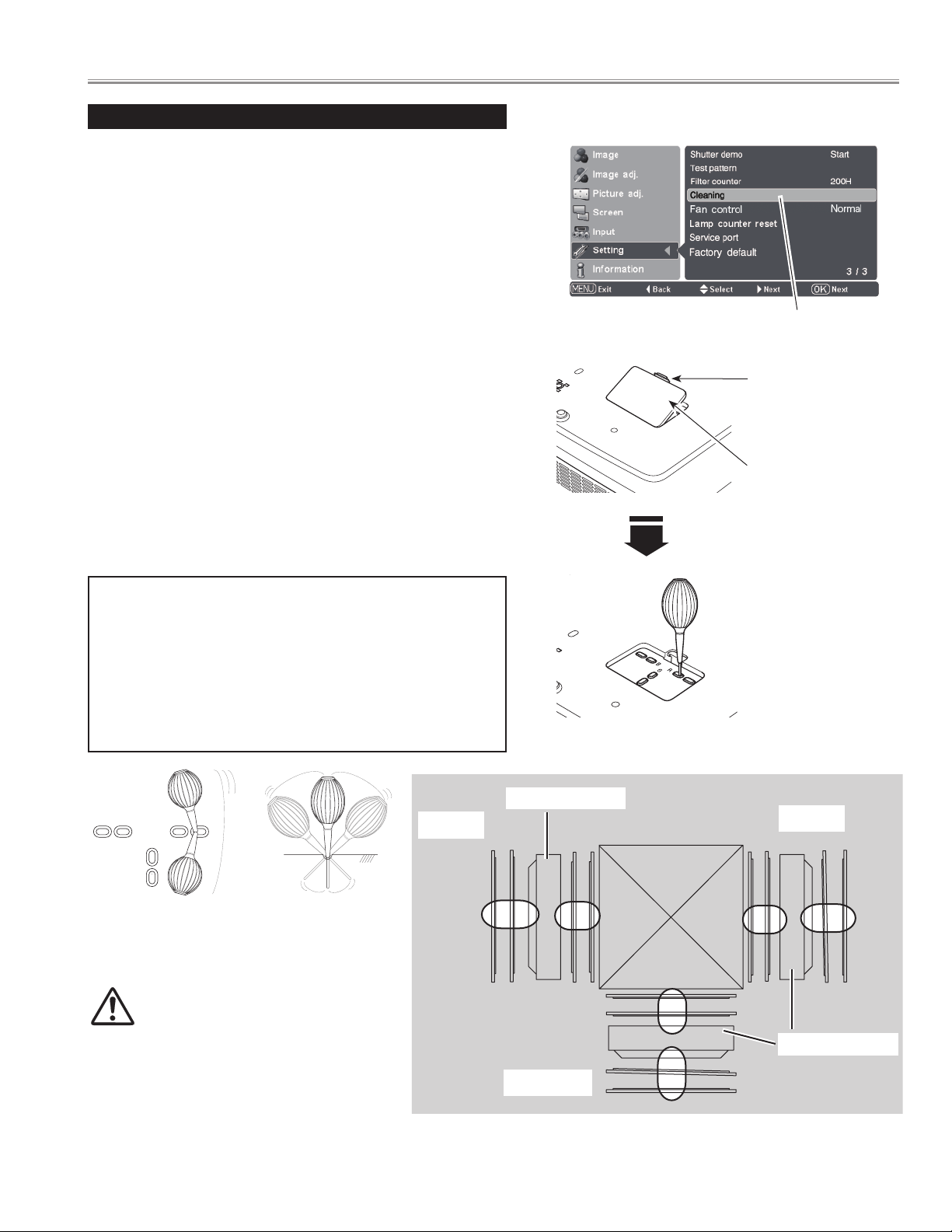
Clean by using the Cleaning function in the Setting Menu
Turn the projector on and press the MENU button to display the
1
On-Screen Menu. Select the Setting Menu with the Point ed
buttons. Press the Point 8 or OK buttons to access the submenu
items.
Select Cleaning and then press the OK or Point 8 buttons. The
2
screen is blacked out temporarily.
Turn the projector over. Put your finger on hole over's tab and
3
pull to open the hole cover.
Put the blower’s nozzle into a hole.
4
Blow air into the projector with the blower watching the position
5
of the dust from the screen.
When cleaning is done, pull the blower out of the hole and
6
replace the hole cover.
Set the projector back into the right position, then press any
7
button on the top control or on remote control to quit the
Cleaning function.
* Do not open the hole cover except when you clean the inside of the
projector to prevent foreign matters from getting into the projector.
If it is open especially while operating the projector, the optical parts
could damage.
Which hole to put the nozzle in?
When you look at the screen:
● When a red spot (dust) is showed up, put the nozzle into the R
panel cleaning holes.
● When a green spot (dust) is showed up, put the nozzle into
the G panel cleaning holes.
● When a blue spot (dust) is showed up, put the nozzle into the
B panel cleaning holes.
Cleaning
Select Cleaning in the
Setting Menu.
Tab
Put your finger on the
hole cover’s tab and
pull.
Hole cover
The nozzle will go no
further than a certain
point when it is put
into the hole. Do not
attempt to push the
nozzle further in, or
it could break and be
stuck inside of the
projector.
Wave the nozzle back and forth inside of the projector.
(Do not attempt to bend the nozzle.)
malfunction with release of cold liquid propellant. We could
not guarantee the malfunction of breakage by using other
tools.
Use only the supplied blower and nozzle.
Do not use a commercially available compressed
air duster. It causes the interior of the projector to
Blue
LCD Panel
Red
LCD Panel
Green
BOTTOM VIEW
- 9 -
Page 10
Maintenance and Cleaning
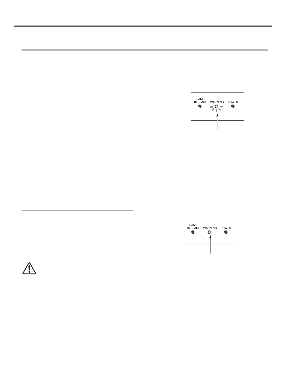
Warning Indicator
The WARNING indicator shows the state of the function that protects the projector. Check the state of the WARNING indicator and the
POWER indicator to take proper maintenance.
The projector is shut down and the WARNING indicator is blinking red.
When the temperature inside the projector reaches a certain level, the
projector is automatically shut down to protect its inside. The POWER
indicator is blinking while the projector is being cooled down. When
the projector has cooled down sufficiently (to its normal operating
temperature), it can be turned on again by pressing the POWER ON/
STAND-BY button.
✔Note:
• The WARNING indicator continues to blink even after the temperature
inside the projector returns to normal. When the projector is turned on
again, the WARNING indicator stops blinking.
Then check the items below.
– Did you provide appropriate space for the projector to be ventilated?
Check the installing condition to see if ventilation slots are not
blocked.
– Has the projector been installed near an Air-Conditioning/Heating
Duct or Vent? Move the installation of the projector away from the
duct or vent.
– Is the air filter clean? Clean the air filter periodically or replace it with a
new one.
TOP CONTROL
WARNING
blinking red
The projector is shut down and the WARNING indicator lights red.
When the projector detects an abnormal condition, it is automatically
shut down to protect the inside of the projector and the WARNING
indicator lights red. In this case, unplug the AC power cord and plug
it, and then turn on the projector once again to verify operation. If the
projector cannot be turned on and the WARNING indicator lights red,
unplug the AC power cord and contact the service station.
CAUTION
DO NOT LEAVE PROJECTOR WITH AC POWER CORD
CONNECTED UNDER AN ABNORMAL CONDITION. IT MAY
RESULT IN FIRE OR ELECTRIC SHOCK.
TOP CONTROL
WARNING
lights light
- 10 -
Page 11
Maintenance and Cleaning
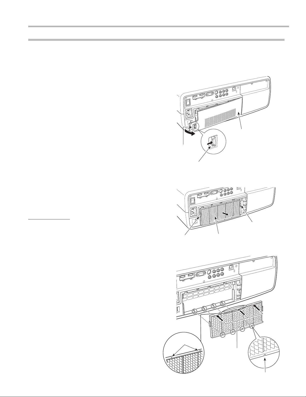
Cleaning the Air Filters
The air filters prevent dust from accumulating on the surface of the optical elements inside the projector. Should the air
filters become clogged with dust particles, it will reduce cooling fans’ effectiveness and may result in a buildup of internal
heat and adversely affect the life of the projector. Clean the air filters by following the steps below.
Press the latch and release it. Take off the filter cover.
1
Pull out the air filter.
2
When taking out the air filter, put your fingers on the air filter’s
tabs and pull. Do not try to pull the delicate filter part.
Remove dust and dirt with a soft brush or a vacuum cleaner. Be
3
careful not to damage the air filter and do not clean it with water.
When the air filter gets dusty and dirty, replace it with a new one.
For ordering the replacement filter, contact your sales dealer.
Put the air filter back into the position. Do not push the delicate
4
filter part. Make sure that the air filter is properly and fully
inserted.
Latch
Press the latch and take
off the filter covers.
Filter cover
Close the filter cover.
5
Reset the filter counter .
6
RECOMMENDATION
We recommend avoiding dusty/smoky environments when operating
the projector. Usage in these environment may cause a poor image
quality.
When using the projector under dusty or smoky conditions, dust
may accumulate on a lens, LCD panels, or optical elements inside the
projector degrading the quality of a projected image.
When the symptoms above are noticed, contact your authorized dealer
or service station for proper cleaning.
CAUTION
Do not operate the projector with the air filters removed. Dust
may accumulate on the LCD panel degrading the picture
quality of the projection mirror. Do not put anything into the air
intake vents. It may result in malfunction of the projector.
Tab
Tab
Air filter
When putting back the air
filter, make sure that the
arrows on the filter are facing
towards the projector.
Arrows
Push here when
you are putting
back the air filter.
Groove
- 11 -
Page 12
Maintenance and Cleaning
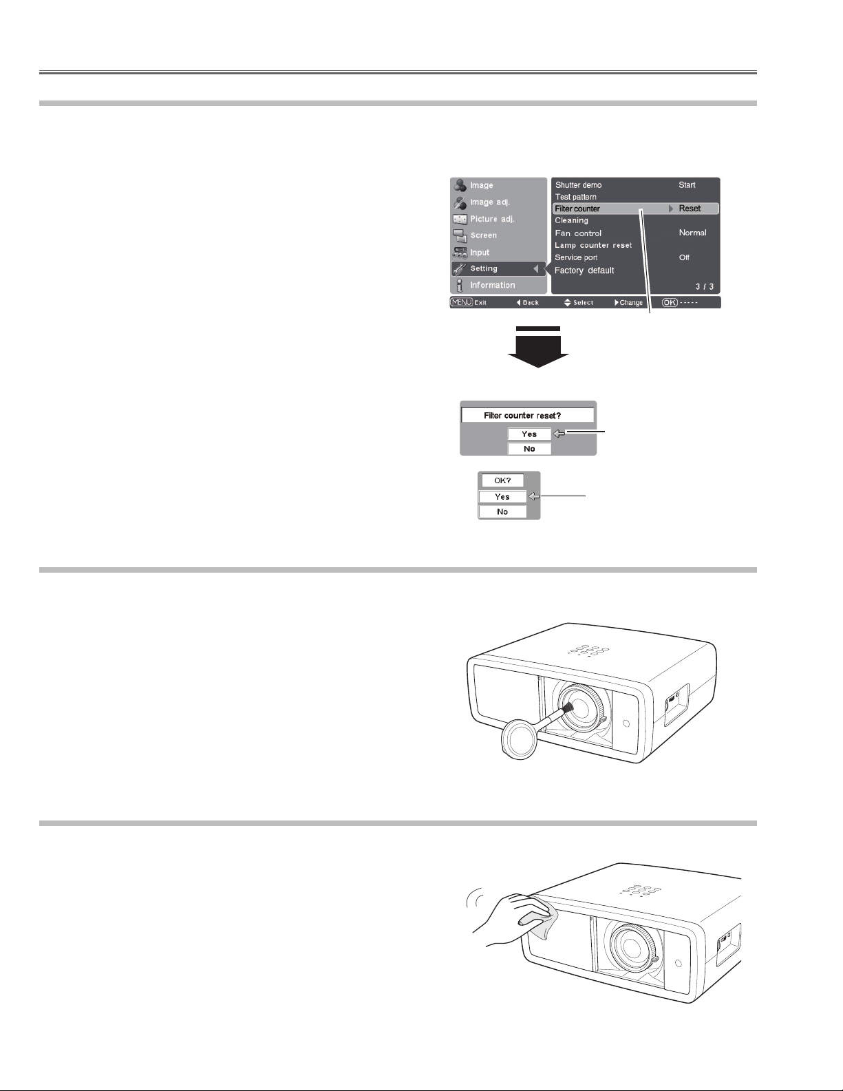
Resetting the Filter Counter
Be sure to reset the Filter counter after cleaning or replacing the air filter.
Turn the projector on and press the MENU button to display the
1
On-Screen Menu. Select the Setting Menu with the Point ed
buttons. Press the Point 8 or OK buttons to access the submenu
items.
Select Filter counter and then use the Point 8 button to select
2
[Reset] and press the OK button. “Filter counter reset?” appears.
Select [Yes] and then press the OK button.
Another confirmation dialog box appears, and select [Yes] to
3
reset the Filter counter.
✔Note:
• Do not reset the Filter counter without cleaning or replacing the air filter. Be
sure to reset the Filter counter only after cleaning or replacing the air filter.
Filter counter
Select Filter counter and
use the Point 8 button to
select [Reset] and press the
OK button. “Filter counter
reset?” appears.
Select [Yes] and press
the OK button, then
another confirmation
box appears.
Select [Yes] again to reset
the lamp counter.
Cleaning the Projection Lens
Unplug the AC power cord before cleaning.
Gently wipe the projection lens with a cleaning cloth that contains
a small amount of non-abrasive camera lens cleaner, or use a lens
cleaning paper or a commercially available air blower to clean the
lens. Avoid using an excessive amount of cleaner. Abrasive cleaners,
solvents, or other harsh chemicals might scratch the surface of the
lens.
When the projector is not in use, make sure that the automatic slide
shutter is closed.
Cleaning the Projector Cabinet
Unplug the AC power cord before cleaning.
Gently wipe the projector body with a dry soft cloth. When the
cabinet is heavily soiled, apply a small amount of mild detergent
and finish with a dry soft cloth. Avoid using an excessive amount of
cleaner. Abrasive cleaners, solvents, or other harsh chemicals might
scratch the surface of the cabinet.
When the projector is not in use, put it in an appropriate carrying case
to protect it from dust and scratches.
- 12 -
Page 13
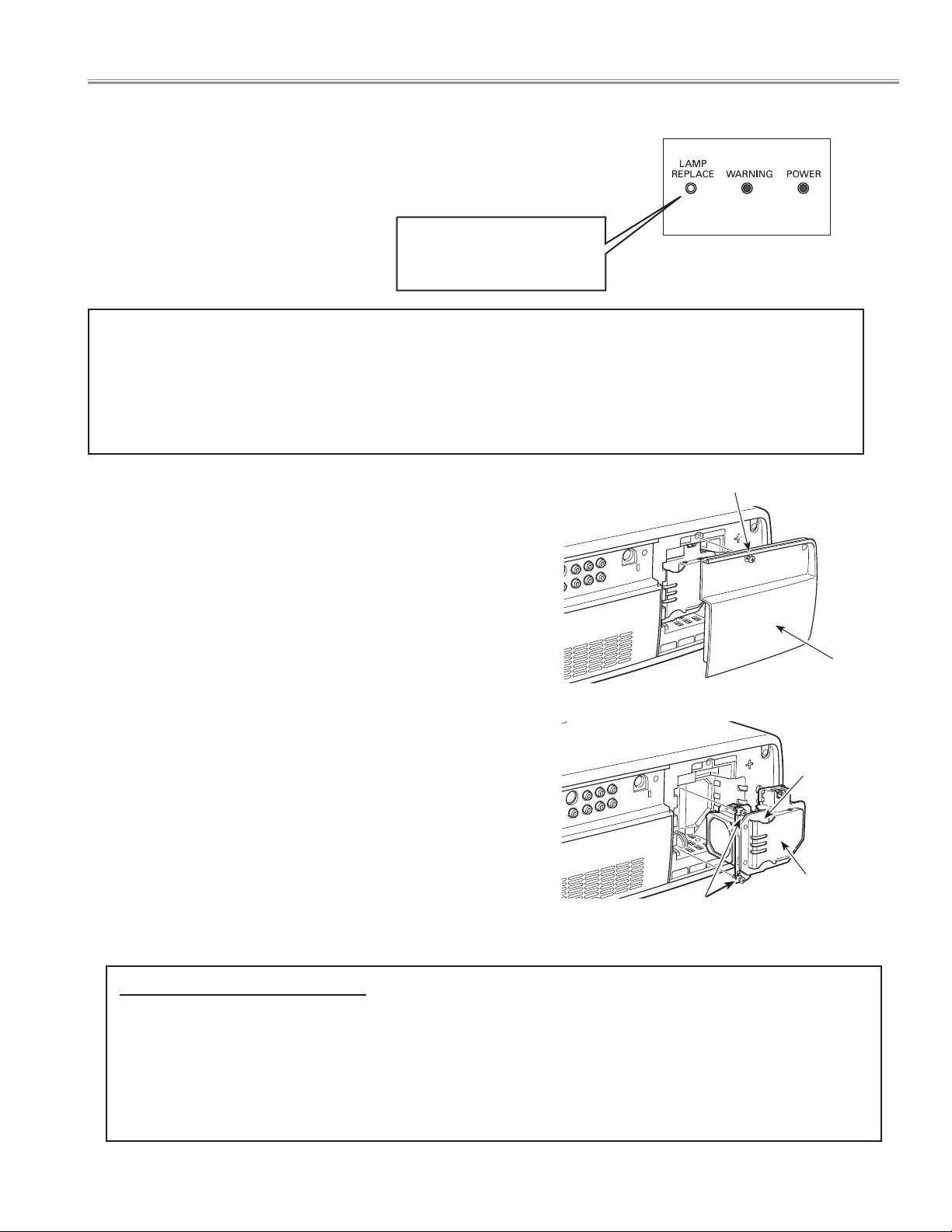
■ Lamp Replacement
When the projection lamp of this projector reaches its end of life,
the LAMP REPLACE indicator emits yellow light. If this indicator
lights yellow, replace the lamp with a new one promptly.
The time when the LAMP REPLACE indicator should light is
depending on the lamp mode.
This indicator lights yellow
when the projection lamp
reaches its end of life.
Top Control
CAUTION
Allow the projector to cool, for at least 45 minutes before
you open the lamp cover. The inside of the projector can
become very hot.
Follow these steps to replace the lamp.
Turn off the projector and unplug the AC power cord. Let the
1
projector cool for at least 45 minutes.
Loosen the screw that secures the lamp cover, and then open the
2
lamp cover.
Loosen the two (2) screws that secure the lamp. Pull out the lamp
3
by using the built in handle.
Replace the lamp with a new one and secure it with the two (2)
4
screws. Make sure that the lamp is set properly. Put the lamp
cover back and secure it with the screw.
Connect the AC power cord to the projector and turn on the
5
projector.
Reset the Lamp replacement counter.
6
CAUTION
For continued safety, replace the lamp with the same type
lamp. Do not drop the lamp or touch the glass bulb! The
glass can shatter and may cause injury.
Screw
Lamp Cover
Handle
Lamp
Screws
ORDER REPLACEMENT LAMP
Replacement lamp can be ordered through your dealer. When ordering a projection lamp, give the following information to the
dealer.
● Model No. of your projector: PLV-Z3000
● Replacement Lamp Type No.: POA-LMP135
(Service Parts No. 610 344 5120)
- 13 -
Page 14
Lamp Replacement
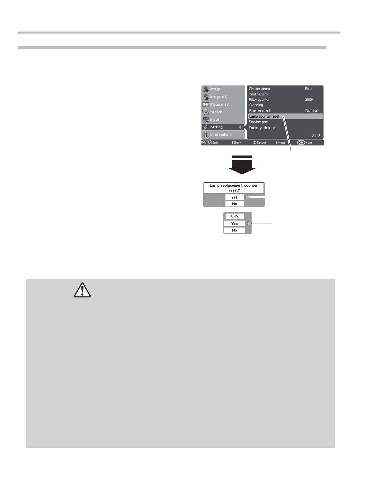
Lamp Replacement Counter
Be sure to reset the lamp replacement counter after the lamp is replaced. When the lamp replacement counter is reset, the LAMP
REPLACE indicator stops lighting.
Lamp counter reset
Turn the projector on and press the MENU button to display the
1
On-Screen Menu. Select the Setting Menu with the Point ed
buttons. Press the Point 8 or OK buttons to access the submenu
items.
Select Lamp counter reset and then press the OK or Point 8
2
buttons. “Lamp replacement counter reset?” appears. Select [Yes]
and then press the OK button.
Another confirmation dialog box appears, and select [Yes] to
3
reset the Lamp replacement counter.
✔Note:
• Do not reset the Lamp replacement counter without implementing lamp
replacement. Be sure to reset the Lamp replacement counter only after
replacing the lamp.
Select Lamp counter reset
and press the OK or Point 8
buttons. “Lamp replacement
counter reset?” appears.
Select [Yes] and press
the OK button, then
another confirmation
box appears.
Select [Yes] again to reset
the lamp counter.
LAMP HANDLING PRECAUTIONS
This projector uses a high-pressure lamp which must be handled carefully and properly. Improper handling may result in
accidents, injury, or create a fire hazard.
● Lamp lifetime may differ from lamp to lamp and according to the environment of use. There is no guarantee of the same
lifetime for each lamp. Some lamps may fail or terminate their lifetime in a shorter period of time than other similar lamps.
● If the projector indicates that the lamp should be replaced, i.e., if the LAMP REPLACE indicator lights up, replace the lamp
with a new one IMMEDIATELY after the projector has cooled down.
(Follow carefully the instructions in the Lamp Replacement section of this manual.) Continuous use of the lamp with the
LAMP REPLACE indicator lighted may increase the risk of lamp explosion.
● A Lamp may explode as a result of vibration, shock or degradation as a result of hours of use as its lifetime draws to an end.
Risk of explosion may differ according to the environment or conditions in which the projector and lamp are being used.
IF A LAMP EXPLODES, THE FOLLOWING SAFETY PRECAUTIONS SHOULD BE TAKEN.
If a lamp explodes, disconnect the projector’s AC plug from the AC outlet immediately. Contact an authorized service station
for a checkup of the unit and replacement of the lamp. Additionally, check carefully to ensure that there are no broken shards
or pieces of glass around the projector or coming out from the cooling air circulation holes. Any broken shards found should
be cleaned up carefully. No one should check the inside of the projector except those who are authorized trained technicians
and who are familiar with projector service. Inappropriate attempts to service the unit by anyone, especially those who are
not appropriately trained to do so, may result in an accident or injury caused by pieces of broken glass.
- 14 -
Page 15
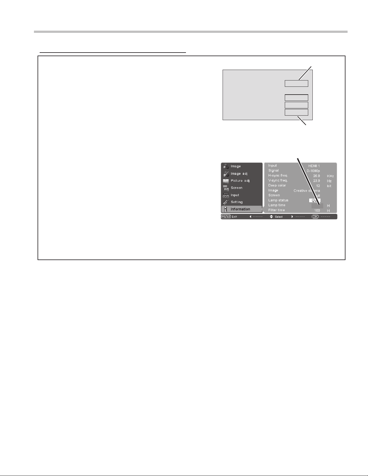
How to check lamp used time
Counter
Projector 475H
Lamp
Normal 100H
Eco 375H
Corresponding value
525H
Lamp Replacement
The LAMP REPLACE indicator will light when the total
lamp used time reaches 3,000 hours. This is to indicate
that lamp replacement is required.
The total lamp used time is calculated by using the below
expression;
Total lamp used time = Teco + Tnormal x (1.5)
Teco: used time in Eco mode
Tnormal: used time in Normal/Auto1/Auto2 mode
You can check the lamp counter following procedure.
1 Press and hold the POWER ON/STAND-BY button on
the projector or the remote control unit for more than
20 seconds.
2 The projector used time and lamp used time will be dis-
played on the screen briefly.
You can also check "Lamp Time" in the "Information
Menu". This value is actual lamp used time.
"Lamp Time" = Teco + Tnormal
Lamp Counter Display
Information Menu
Projector used time
Total lamp used time
Total lamp used time (actual)
475
- 15 -
Page 16
Filter counter
Reset
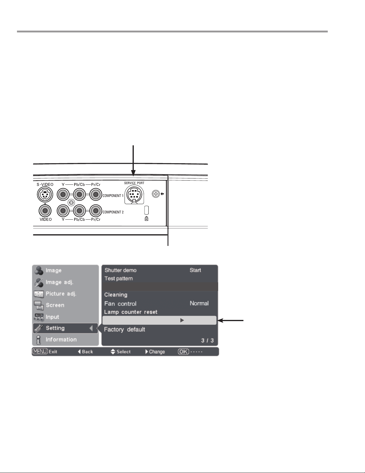
Service port
Off
■ Service Port
Switch of standby mode
Service port "O " : Super standby mode
Service port "On" : Normal standby mode
The service port is factory default set "OFF".
When the service port is used, the item of the service port of the setting menu is changed to "ON".
(The service port cannot be used in the state of "OFF". )
Change to "OFF" after servicing ends.
(Power consumption when standing by increases in the state of "ON". )
Service Port
- 16 -
Page 17
■ Mechanical disassemblies
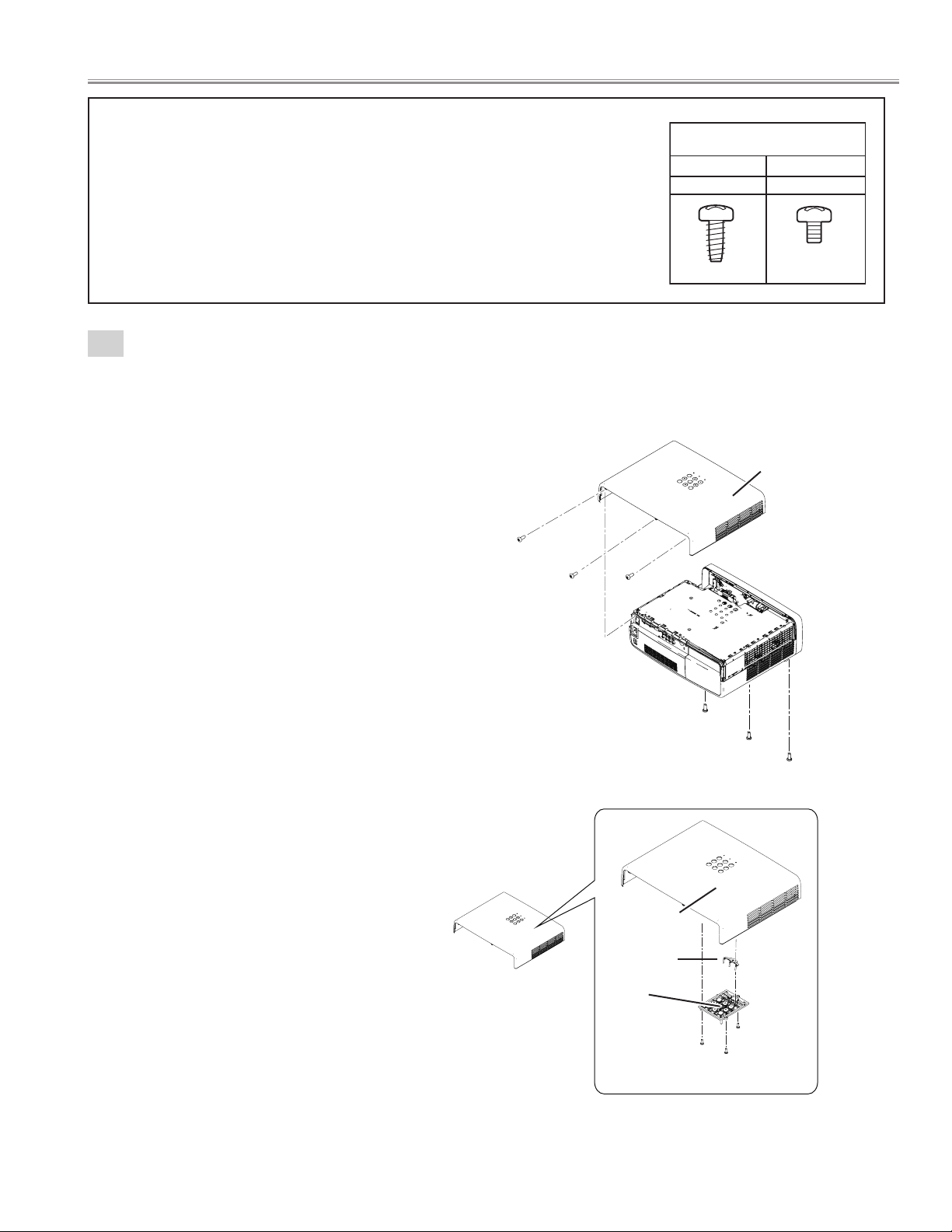
Screws Expression
(Type Diameter x Length ) mm
T type M Type
Tapping screw Machine screw
A
A
A
B
B
B
Disassemble should be made following procedures in numerical order.
Following steps show the basic procedures, therefore unnecessary step may be
ignored.
Caution:
The parts and screws should be placed exactly the same position as the original other-
wise it may cause lose of performance and product safety.
The wiring method of the leads and ferrite cores should be returned exactly the same
state as the original, otherwise it may cause lose of performance and product safety.
1
Cabinet top ass'y removal.
1. Remove the 3 screws-A(M3x10) from the bottom side.
2. Remove the 3 screws-B(M3x8) and remove the Cabinet top ass'y.
3. Remove the 3 screws-C(T2.6x6), remove the Button and DEC. LED.
Cabinet top assy
Cabinet top assy
Cabinet top
DEC. LED
Button
C
- 17 -
C
C
Page 18
Mechanical disassemblies
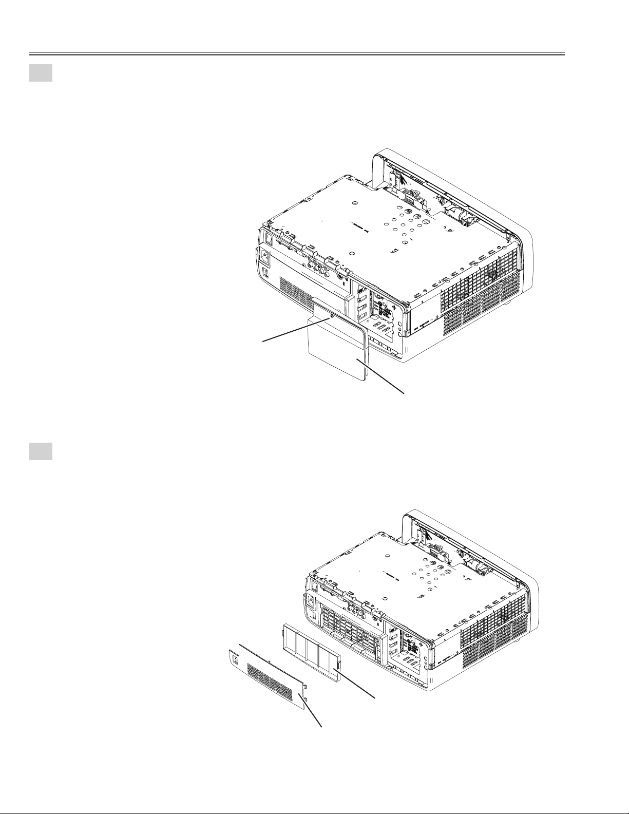
2
Lamp cover ass'y removal.
1. Loosen the screw-A and remove the Lamp cover ass'y.
3
Filter removal.
1. Remove the Filter cover and Filter.
A
Lamp cover ass'y
Filter cover
- 18 -
Filter
Page 19
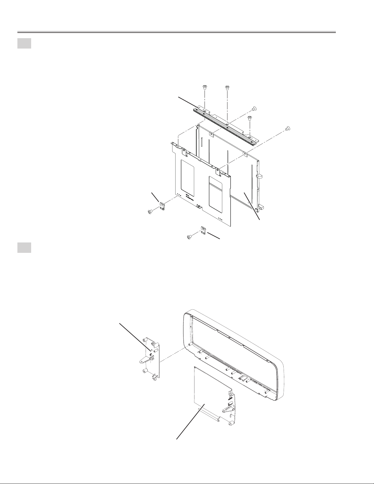
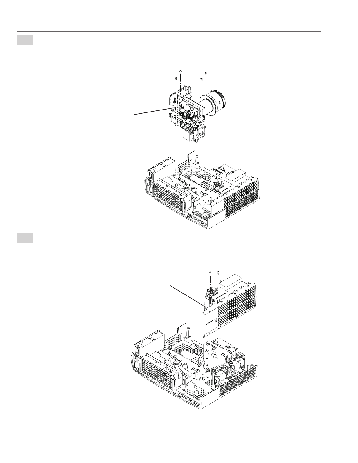
4
AV panel removal.
1. Remove the 2 screws-A(M3x8), remove the screw-B(T3x8) and remove the AV panel.
A
B
Mechanical disassemblies
A
5
Main PWB shield plata(top) removal.
1. Remove the 2 screws-C(M3x6) and remove the Shield plate (Main board-front) .
2. Remove the 9 screws-A(M3x6), remove the screw-B(M3x10) and remove the Shield plate
(Main board-top) .
AV panel
A
A
C
A
A
A
C
B
Shield plate
(Main board front)
A
A
A
A
- 19 -
Shield plate
(Main board top)
Page 20
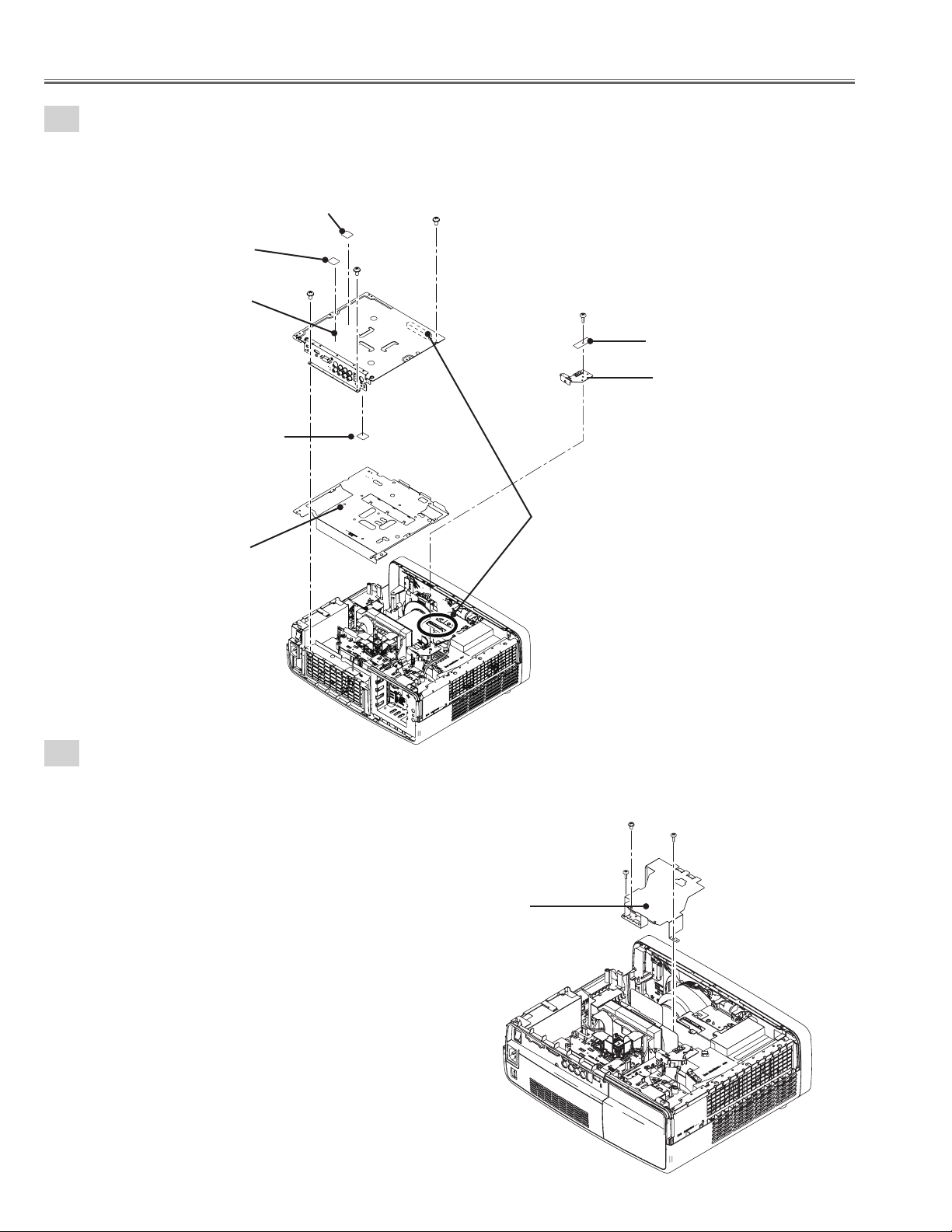
Mechanical disassemblies
6
Main PWB removal.
1. Remove the 3 screws-A (M3x6), remove the Main board and remove the Shield plate (Main board-BTM).
2. Remove the screw-B (T3x8), remove the Filter Net board and remove the Main board holder.
Heat sink sheet (IC4401)
Heat sink sheet (IC301)
Main board
Heat sink sheet (IC5201)
Shield plate
(Main board BTM)
A
Caoution;
Do not lose the heat sink sheet.
A
A
B
Filter Net board
Main board holder
Caoution;
Be carefull do not damage the
connector
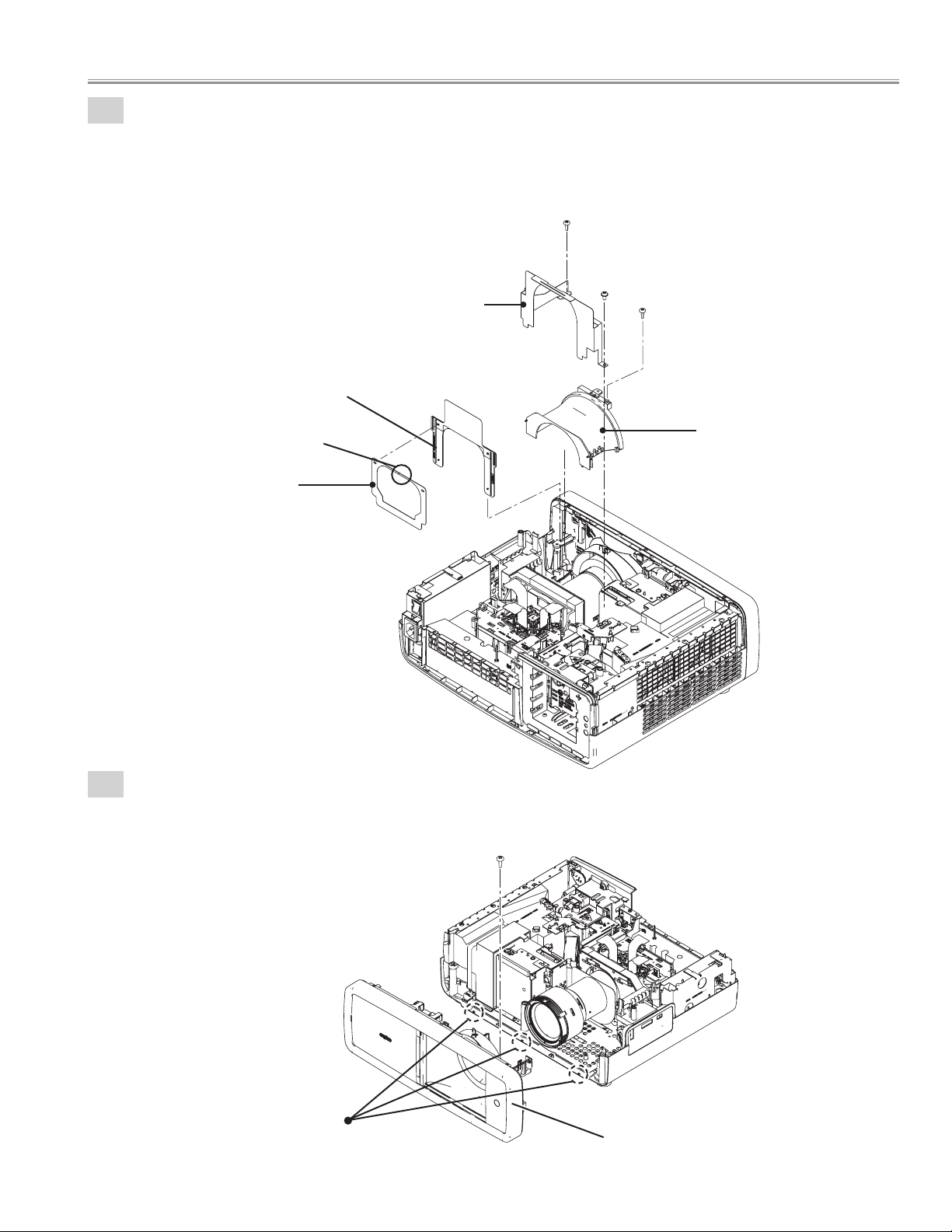
7-1
Cover lens top removal.
1. Remove the screw-A (M3x6), 2 screwS-B (T3x8) and remove the
Shield plate (Cover lens).
Shield plate
(Cover Lens)
A
B
B
- 20 -
Page 21
7-2
Cover lens top removal.
1. Remove the screw-A (T3x8), screw-B (M3x6) and remove the Bracket.
2. Remove the screw-C (T3x8) and remove the Cover lens top upward.
3. Remove the Spacer sheet assy and remove the Spacer sheet-A.
Bracket
Spacer sheet assy
Mechanical disassemblies
A
B
C
Slit
Spacer sheet-A
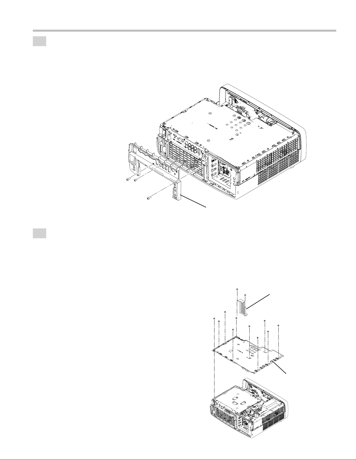
8
Cabinet front ass'y removal.
1. Remove the screw (T3x8) and remove the Cabinet front ass'y forward.
Cover lens top
Hooks
Cabinet front ass'y
- 21 -
Page 22
Mechanical disassemblies
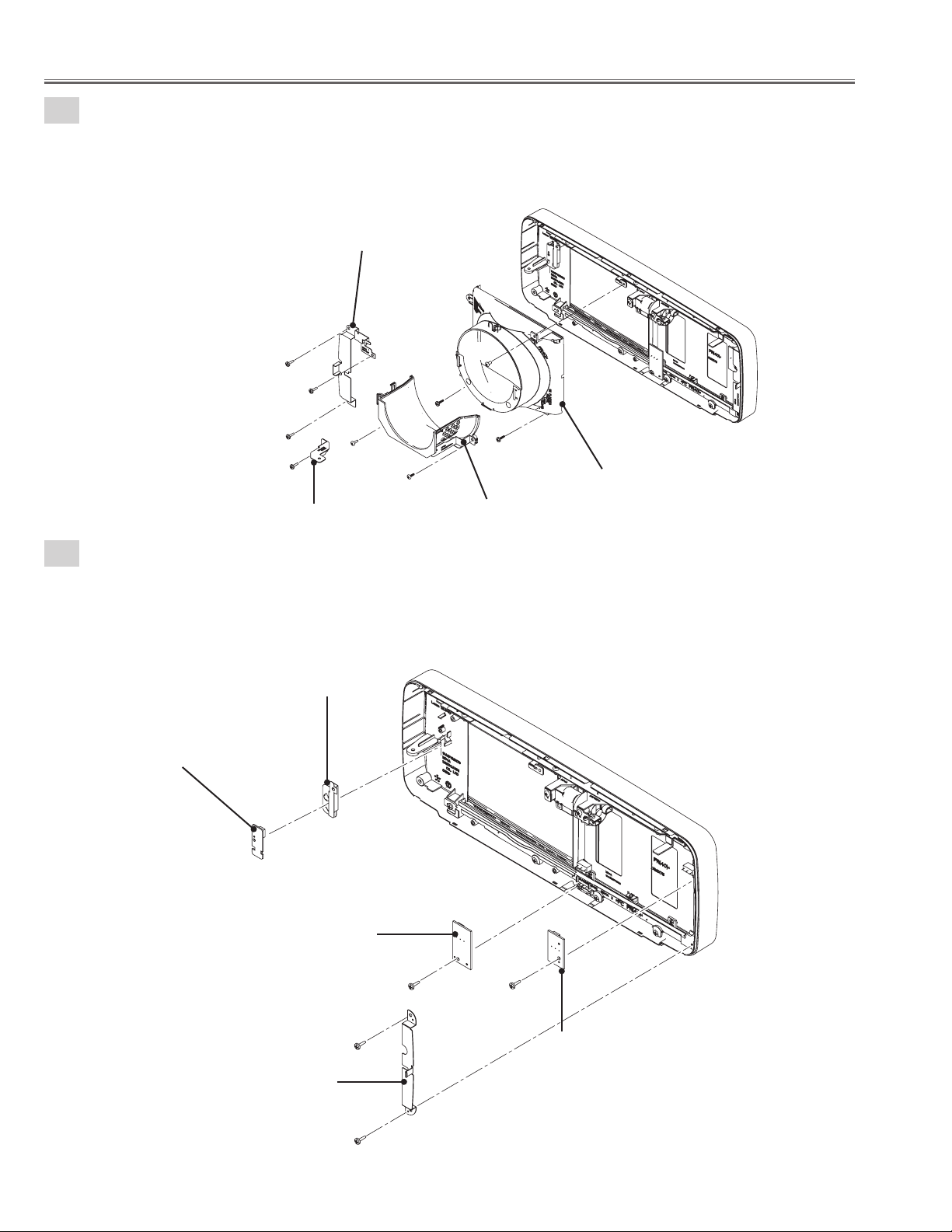
9-1
Cabinet front ass'y disassembly.
1. Remove the 3 screws-A(T3x10) and remove the Mounting front-a.
2. Remove the screw-B(T3x10) and remove the Mounting front-C.
3. Remove the screw-C(M3x6), remove the 2 screws-D(T3x10) and remove the Cover lens bottom assy.
4. Remove the 2 screws-E(T3x8) and remove the Cover lens bottom-a.
Mounting front-A
A
A
A
B
Mounting front-C
9-2
Cabinet front ass'y disassembly.
1. Unhook and remove the R/C board, remove the Mounting front RC.
2. Remove the screw-A(T3x10) and remove the Shutter SW-B board.
3. Remove the 2 screws-B(T3x10) and remove the Mounting front-B.
4. Remove the screw-C(T3x10) and remove the Shutter SW-A board.
Mounting front-RC
R/C board
E
D
E
Cover lens bottom-A
C
D
Cover lens bottom
Shutter SW-B board
Mounting front-B
A C
B
B
- 22 -
Shutter SW-A board
Page 23
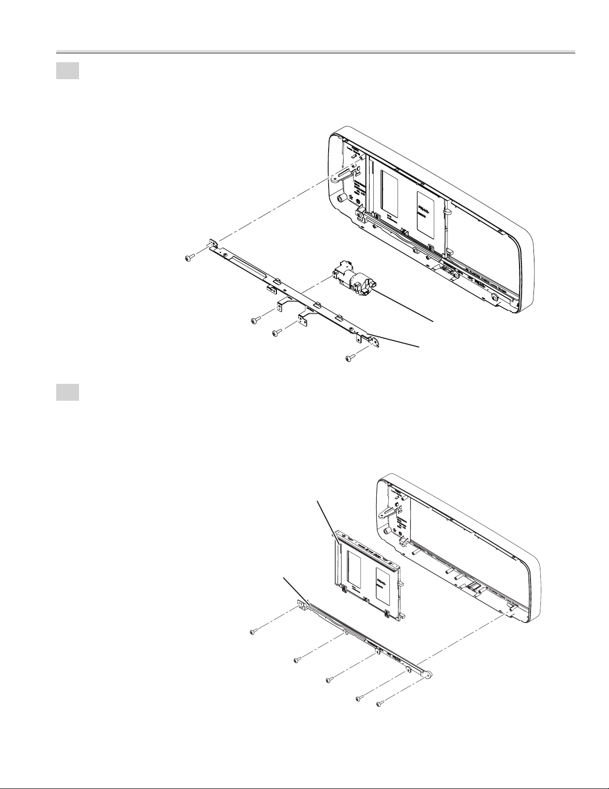
9-3
Cabinet front ass'y disassembly.
1. Remove the 2 screws-A (T3x10) and remove Shutter rail top unit.
2. Remove the 2 screws-B (T3x10) and remove the Shutter motor.
A
Mechanical disassemblies
B
B
9-4
Cabinet front ass'y disassembly.
1. Remove the 5 screws (T3x10) and remove the Shutter rail bottom.
2. Remove the Shutter panel unit.
Shutter panel unit
Shutter rail bottom
Shutter motor
A
Shutter rail top unit
- 23 -
Page 24
Mechanical disassemblies
9-5
Cabinet front ass'y disassembly.
1. Remove the 3 screws-A (M2.6x4) and remove the Gear.
2. Remove the 2 screws-B (M2.6x4) and remove the Shutter panel.
3. Remove the 2 screws-C (M2.6x4) and remove the 2 spacers.
9-6
Cabinet front ass'y disassembly.
1. Remove the Panel front-A.
2. Remove the Panel front-B.
Spacer
C
Gear
A
C
Spacer
A
B
A
Shutter panel
B
Panel front-A
Panel front-B
- 24 -
Page 25
Mechanical disassemblies
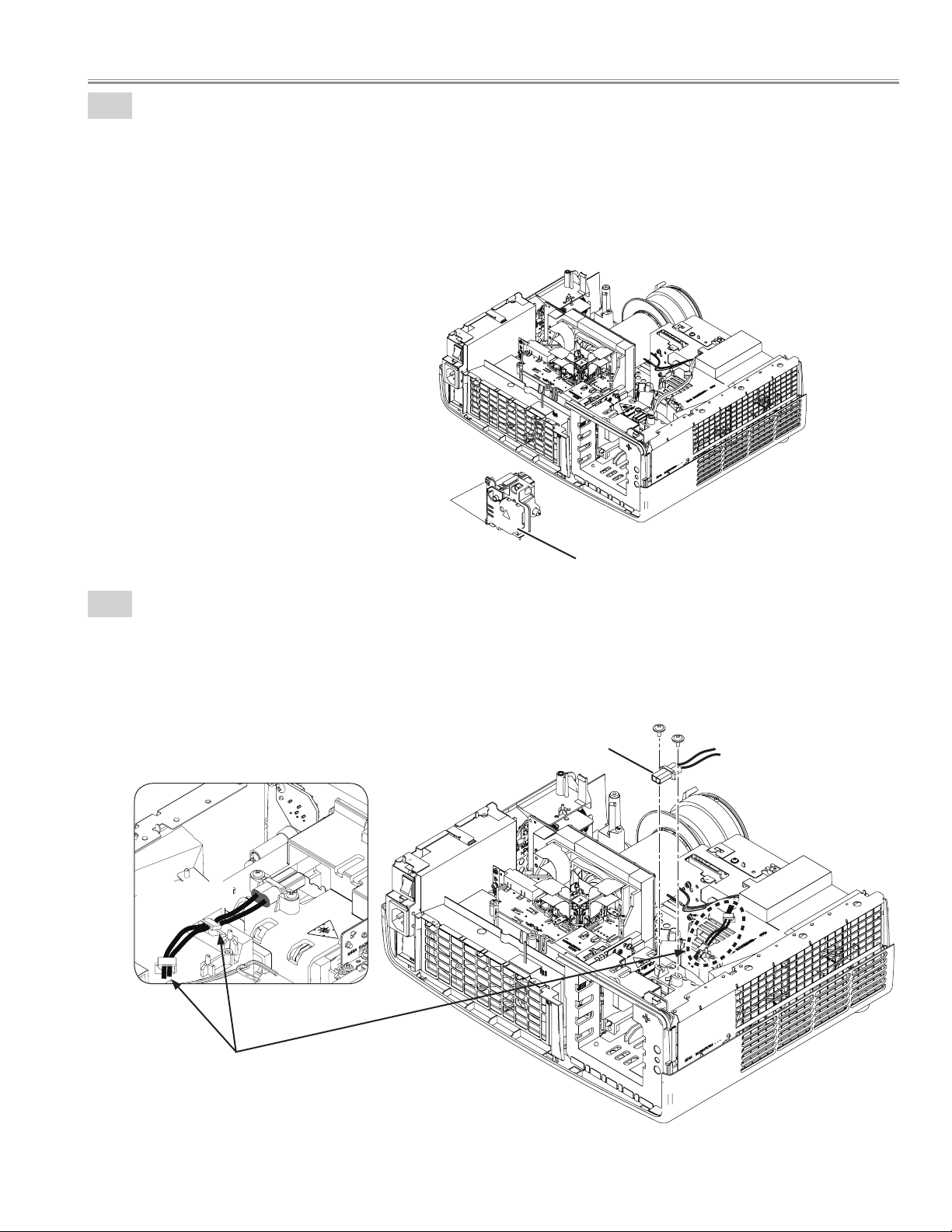
10-1
Lamp unit removal.
1. Loosen the 2 screws-A and remove the Lamp unit.
A
10-2
Lamp unit
Lamp connector removal.
1. Remove the 2 screws(T3X6) and remove the Lamp connector.
Lamp connector
Ballast Cable
Caution:
When remove the Lamp ballast cable,
be carefull not to damade the cable.
- 25 -
Page 26
Mechanical disassemblies
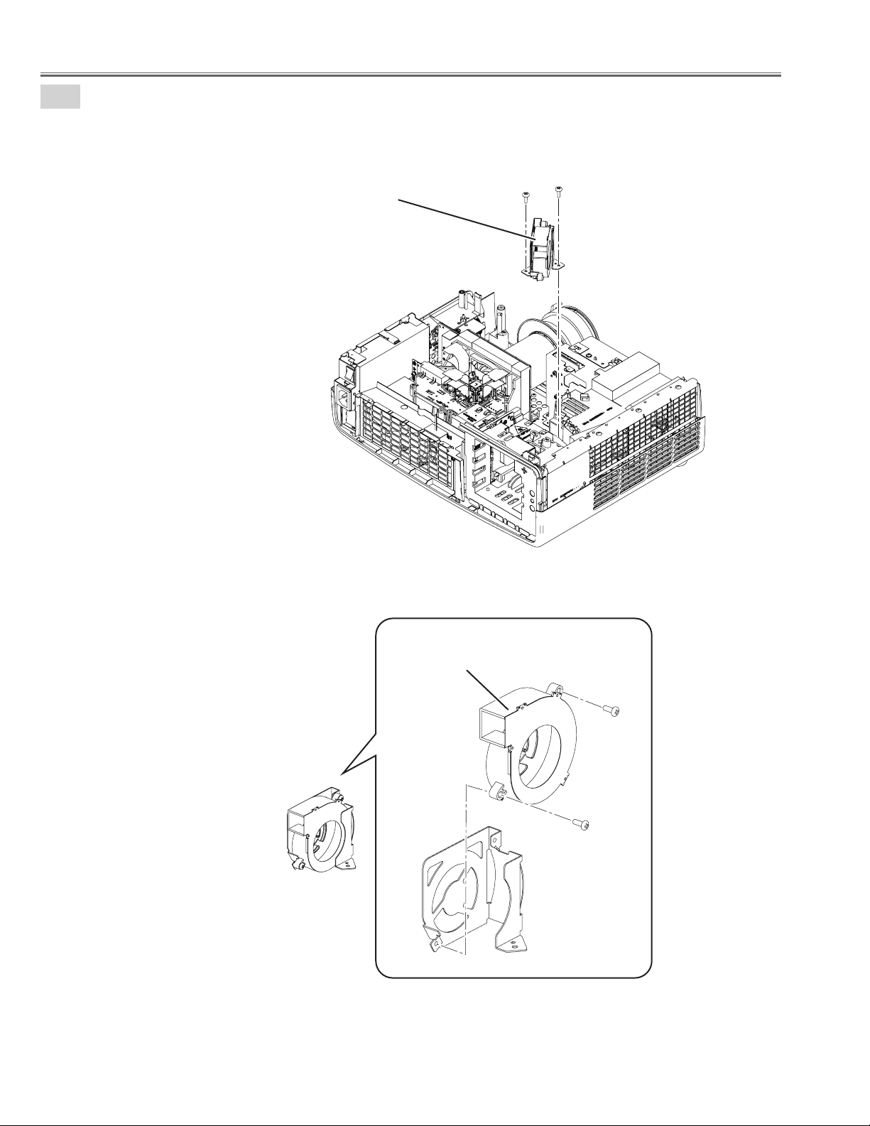
10-3
Fan(FN902) removal.
1. Remove the 2 screws-A (T3x8) and remove the Fan unit.
2. Remove the 2screws-B (M3x8) and remove the Fan(FN902).
Fan unit
A A
Fan(FN902)
B
B
- 26 -
Page 27
Mechanical disassemblies
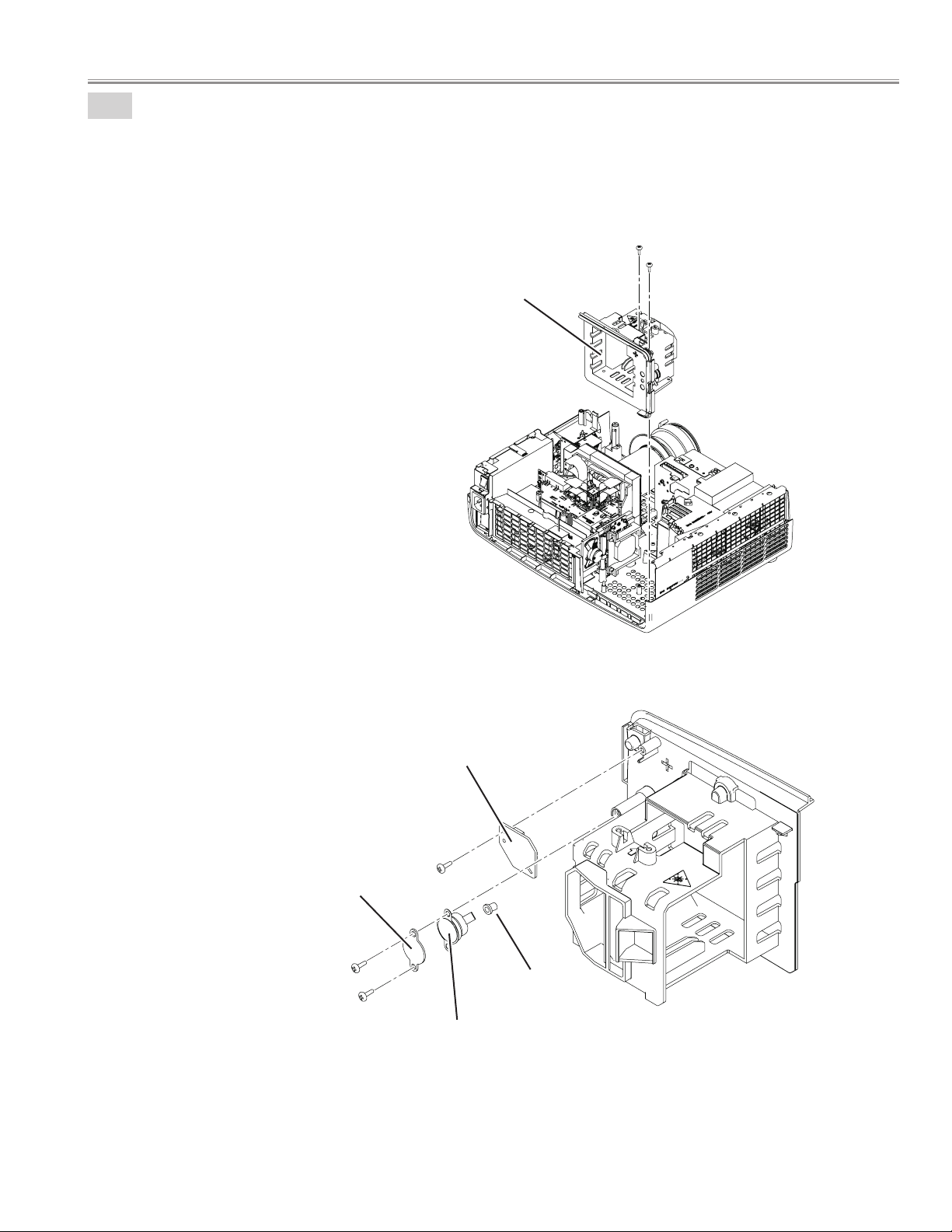
10-4
Lamp unit holder removal.
1. Remove the 2 screws-A (T3x8) and remove the Lamp unit holder.
2. Remove the screwB (T3x8) and remove the Lamp cover switch(SW8803) board.
3. Remove the 2screws-C (T3x8), remove the Spacer, remove the Cap and remove the Thermal switch(SW902).
A
A
Lamp unit holder
Lamp cover switch(SW8803) board
B
Spacer
C
C
Thermal switch(SW902)
- 27 -
Cap
Page 28
Mechanical disassemblies
11
Optical removal.
1. Remove the 4 screws (T3x10) and remove the Optical unit.
Optical unit
12-1
Cover duct EXH removal.
1. Remove the 2 screws (T3x8) and remove the Cover duct EXH.
Cover duct EXH
- 28 -
Page 29
Mechanical disassemblies
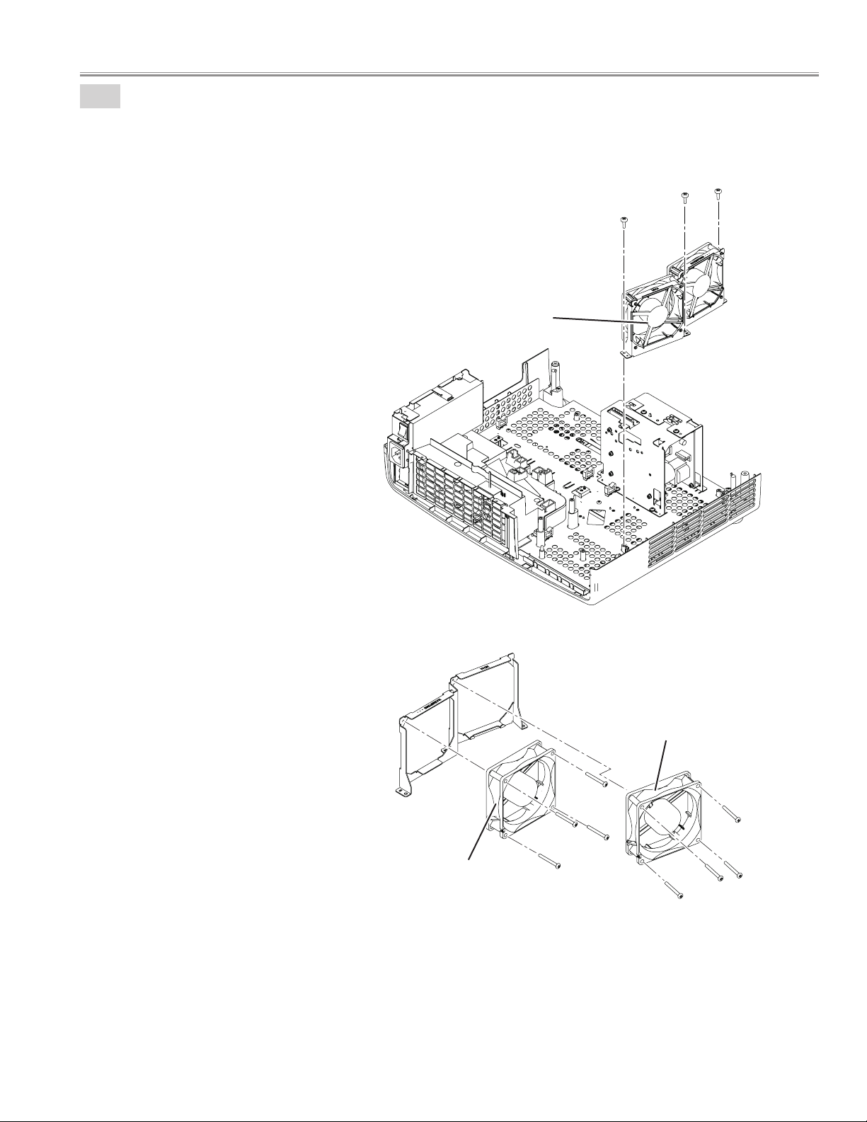
12-2
Exhaust Fan (FN901, FN903) removal.
1. Remove the 3 screws-A (T3x8) and remove the Exhaust fan unit.
2. Remove the 8 screws-B (M3x28) and remove the Exhaust fan FN901, FN903.
Exhaust fan unit
A
A
A
- 29 -
FN903
FN901
B
B
B
B
B
B
B
B
Page 30
Mechanical disassemblies
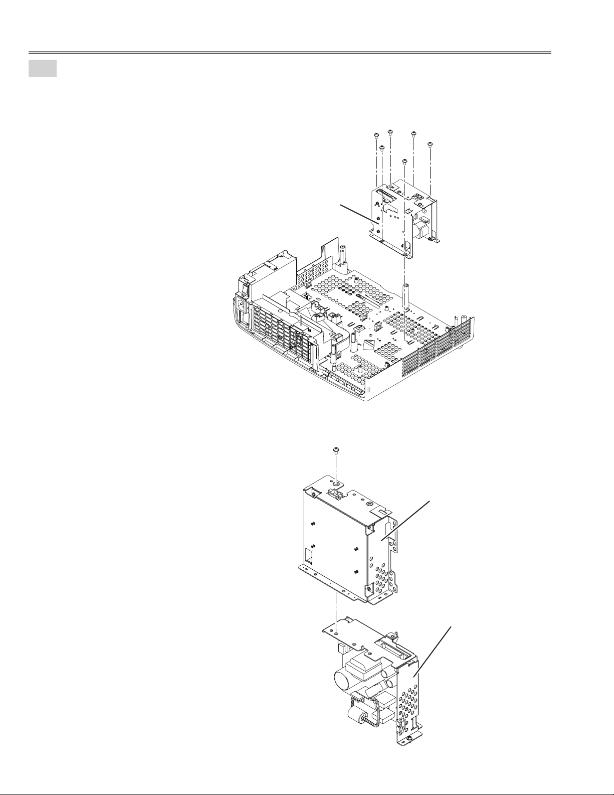
13
Power unit removal.
1. Remove the 6 screws-A (M3x6) and remove the Power & Ballast unit.
1. Remove the screw-B (M3x6) and remove the Power & Ballast unit.
Power & Ballast unit
A
A
A
A
A
A
B
Ballast unit
Power unit
- 30 -
Page 31

14
Filter board unit removal.
1. Remove the 2 screws (M3x6) and remove the Filter unit.
Mechanical disassemblies
Filter board unit
Spacer
Filter board
- 31 -
Page 32

Mechanical disassemblies
15
Duct unit removal.
1. Remove the 7 screws (T3x8) and remove the Duct panel top.
2. Remove the Spacer and remove the Themistor(TH902).
3. Remove the FN904 and FN905.
4. Remove the Duct panel bottom.
Spacer
Themistor(TH902)
FN905
Duct panel top
Duct panel bottom
FN904
- 32 -
Page 33

16
Cabinet bottom unit desassemblies.
1. Remove the 6 screws-A (T3x8) and remove the Shield cabinet bottom.
2. Remove the 2 screws-B (T3x8) and remove the Adjustor.
3. Remove the 3 nuts.
Mechanical disassemblies
A
Shield cabinet bottom
Adjustor
A
A
B
A
A
A
Nuts
Adjustor
B
- 33 -
Page 34

■ Optical disassemblies
Optical unit
1
Lens shift panel remonal.
1. Remove the screw-A (M3x6), remove the shield plate.
2. Remove the screw-B (M3x6), remove the Lens shift panel and remove the Slide cover.
Shield plate
Slide cover
A
B
Lens shift panel
- 34 -
Page 35

2
LCD panel / prism ass'y removal.
1. Remove the Shield Light Plate upward.
2. Remove the 4 screws-A (M2.5x4) and remove the LCD panel / prism ass'y.
A
A
LCD panel / prism ass'y
A
A
Optical disassemblies
Shield Light Plate
Note; Do not replace the LCD panel separately
otherwise it can not obtain proper picture.
Do not touch the prism, the LCD panel and
electrode of flexible cable.
- 35 -
Page 36

Optical disassemblies
R
L
Panel Type Check
There are 2 types combination of the LCD Panel/Prism Ass'y and the optical unit, named Type-L and Type-R.Since both have no
compatibility, each type should be combined with the same type, and the specificparts should be used. If not, the poor optical
characteristics may degrade the quality of a projected image.
LCD panel / prism ass'y (Type-R)
IMPORTANT NOTICE on LCD Panel/Prism Ass'y Replacement
LCD panels used for this model can not be replaced separately. Do not disassemble the LCD Panel/Prism Ass'y.
These LCD panels are installed with precision at the factory. When replacing the LCD panel, should be replaced whole of
the LCD panels and prism ass'y at once.
After replacing LCD Panel/Prism ass'y, please check the following adjustments.
- Check the "White Balance Adjustment" and "Common Center Adjustment" following to chapter "Electrical
Adjustment".
- Check the white uniformity on the screen.
If you find the color shading, please adjust the white uniformity by using the proper computer and "Projector
Service Tool" software supplied separately. The software can be ordered as follows;
Projector Service Tool Ver. 4.10
Service Parts No. 610 337 8787
LCD panel / prism ass'y (Type-L)
- 36 -
Page 37

3
Polarized glasses removal.
1. Remove the 3 screws-A (M2.5x5) and remove the 3 Holders (R,G,B).
2. Remove the 3 screws-B (M2.5x6) and remove the 3 Stoppers (R,G,B).
3. Remove the 3 Optical filteres and remove the 3 Polarized glasses (IN) ass'y (R,G,B).
A
B
Optical lter (IN/R)
Stopper
Optical disassemblies
Polarized glass (IN/R)
Optical lter (IN/G)
Polarized glass (IN/G)
A
B
Holder
B
A
Polarized glass (IN/B)
Optical lter (IN/B)
Blue-Polarized glass (IN)
Thermistor (TH901)
- 37 -
Page 38

Optical disassemblies
4
Lamp iris unit removal.
1. Remove the 3 screws-A (T3x10) and remove the lamp iris cover.
2. Remove the screw-B (T3x10) and remove the Lamp Iris unit.
A
A
A
Lamp iris cover
B
Lamp Iris unit
- 38 -
Cinema lter switch
(SW903)
M2.5x4
M2.5x6
Page 39

5
Optical Filter(Cinema Filter) and Motor unit removal.
1. Remove Optical filter (Cinema Filter) unit upward.
2. Remove the 2 screws-A (T3x10) and remove the Optical shutter Motor.
Optical Filter unit
Optical disassemblies
Optical Filter unit
Optical Shutter Motor
A
A
Sttoper
The marker
comes this up
side.
Optical Filter
(Cinema Filter)
Holder Optical Filter
- 39 -
Page 40

Optical disassemblies
6
Lens shift unit removal.
1. Remove the 4 screws (M3x6) and remove the Lens shift unit.
Lens shift unit
7
Projection lens removal.
1. Remove the 4 screws (M2.6x6) and remove the Projection lens.
Spacer
Projection lens
- 40 -
Page 41

● Optical parts location and direction
L01R ASSY, LCD PNL/SM R-MF4A
L01L ASSY, LCD PNL/SM L-MF4A
L02 LENS, PROJECTOR
L03R/L03L COMPL, OPTICAL R/L-MF4A
L03-1R OPTICAL FILTER (HPO)90
L03-1G OPTICAL FILTER (HPO)90
L03-1B OPTICAL FILTER (HPO)90
L03-2R POLARIZED GLASS (IN/R)
L03-2G POLARIZED GLASS (IN/G)
L03-2B POLARIZED GLASS (IN/B)
L03-3 LENS, CONDENSER (G)
L03-4 LENS, CONDENSER (B)
L03-5 LENS, CONDENSER (R)
L03-6 MIRROR (B)
L03-7 MIRROR (R)
L03-8 OPTICAL FILTER (R)
L03-9 PRISM (PBS)
L03-10 DICHROIC MIRROR (B)
L03-11 DICHROIC MIRROR (G)
L03-12 LENS, INTEGRATOR (IN)
L03-13 LENS, INTEGRATOR (OUT) UV
L04 OPTICAL FILTER (CINEMA)
L03-5
L03-7
L03-1G
L03-2G
Optical disassemblies
L03-8
L03-7
L03-5
L03-2R
L03-1R
L04
L03-9
L03-13
L03-12
L03-11
L03-3
L03-10
L01R
L01L
L02
L03-1B
L03-2B
L03-4
L03-6
L03R
L03L
- 41 -
Page 42

Optical disassemblies
Chamfer corner comes this side up.
Chamfer corner comes
this side.
Film attached side comes
this side.
DICHROIC MIRROR
Chamfer corner comes
this side up.
OPTICAL FILTER (R) CONDENSER LENS (G, B)
The marker comes this
up side.
The marker comes this
up side.
PBS
Flat surface side comes
this side.
Film attached side
comes this side.
OPTICAL FILTER
Film attached side comes
this side.
POLARIZED GLASS (IN)
- 42 -
Page 43

The marker comes this
up side.
OPTICAL FILTER(CINEMA)
Optical disassemblies
The marker comes this
surface side.
Reflective surface
MIRROR
- 43 -
Page 44

■ Adjustments
Adjustments after Parts Replacement
● : Adjustment necessary ❍ : Check necessary
Disassembly / Replaced Parts
Contrast Adjustment
Adjustments
Optical
R-Contrast adjustment
G-Contrast adjustment
B-Contrast adjustment
Fan minimum voltage adjustment
Fan maximum voltage adjustment
Auto calibration adjustment [PC]
Electrical Adjustments
Auto calibration adjustment [Composite] NTSC
Auto calibration adjustment [Component] 480i
Auto calibration adjustment [Component] 480p
Auto calibration adjustment [Component] 720p
Auto calibration adjustment [Component] 1080i
Common center adjustment
Color Correction
Color Shading Contrast adjustment
Read/Wright of LCD panel gamma data
LCD/
Prism Ass’
❍ ❍ ● ●
❍ ❍ ● ●
❍ ❍ ● ●
● ●
❍ ❍
❍ ❍
❍ ❍
COMPL,
OPTICAL
UNIT
Optical Filter
R G B R G B
Polarized Glass
Power
Board
● ●
● ●
Main
Board
●
●
●
●
●
●
■ MEMORY IC REPLACEMENT
IC1391 on the main board stores the data for the service
adjustments, and should not be replaced except for the
case of defective device.
If replaced, it should be performed the re-adjustments following to the “Electrical Adjustments”.
The data of lamp replacement monitor timer is stored in
the IC1391.
Please note that the lamp replace counter is reset when
the memory IC (IC1391) is replaced.
(Lamp replace counter can not be set to the previous
value.)
● Caution to memory IC replacement
When IC1391 is replaced with new one, the CPU writes
down the default data of the service adjustments to the
replaced IC, refer to the service adjustment table. As these
data are not the same data as factory shipped data, it
should be required to perform the re-adjustments following to the “Electrical Adjustments”.
Please note that in this case the lamp replace counter will
be reset.
● Caution of Main Board replacement (in the case
IC1391 is not defective)
When the main board is replaced, IC1391 should be
replaced with the one on previous main board. After
re p lacement, it shou l d be required to per form the
re-adjustments following to the “Electrical Adjustments”.
In this case, the lamp replace counter can be kept the
value as before.
- 44 -
Page 45

■ Optical Adjustment
Before taking optical adjustments below, remove the Cabinet Top following to the "Mechanical Disassemblies".
Adjustments require a 2.0mm hex wrench, Philips Screwdriver and a slot screwdriver. When you adjust Integrator lens or Relay
lens adjustment, you need to disconnect some connectors and FPC cables of LCD panels on the main board.
Note:
Do not disconnect connectors on the main board, because the projector can not turn on or operate properly for
adjustment.
WARNING : USE UV RADIATION EYE AND SKIN PROTECTION
DURING SERVICING
CAUTION: To prevent suffer of UV radiation, those adjustments
must be completed within 25 minutes.
(1) Contrast adjustment
Polarized glass (R)
Fixed (LENS RELAY_OUT)
Do not adjust
Optical filter (R)
(1) Contrast adjustment
Polarized glass (G)
Optical filter (G)
Fixed (LENS CONDENSOR_OUT)
Do not adjust
(1) Contrast adjustment
Polarized glass (B)
Optical filter (B)
- 45 -
Page 46

Optical Adjustmeent
1. Contrast adjustment (Polarized glass and Optical filter)
[ Before Adjustment ]
- Input a 100% of black raster signal.
- Input image mode : Dynamic
1. Loosen a screw A on the optical base which you intend to adjust.
2. Adjust the slot B to obtain the darkest brightness on the screen.
(Polarized glass adjustment.)
3. Adjust the slot C to obtain the darkest brightness on the screen.
(Optical filter adjustment.)
4. Tighten the screw A to fix the polarized glass mounting base.
Repeat steps 1 to 4 for remaining polarized glasses.
Blue Optical lter is not adjusted.
Polarized glass
Optical lter
Slot-B
Slot-C
Screw-A
Slot-C
Slot-B
Screw-A
Slot-C
Slot-B
- 46 -
Page 47

■ Electrical Adjustment
Normal Mode "S" mark display
MENU
Service Mode
Input VIDEO
Image
Natural
Group No. Data
SANYO
0 +1
R 1.00
ME4A
102
Ver.
Service Mode
Service mode
+
DOWN
POWER
ON/STAND-BY
INPUT
UP
+
S
● Service Adjustment Menu Operation
◆ To enter service mode
To enter service mode, press and hold the "MENU" and
"INPUT" buttons on the projector simultaneously for 5 seconds.
(Or press and hold the "MENU" button on the remote control
unit for 20 seconds.) The "S" mark appears on the screen. While
the "S" mark is displayed on the screen, press and hold the "
POINT UP" and "POINT DOWN" buttons on the projector or
"SCREEN" button on the remote control unit for more than 3
seconds. As shown in a figure, a service mode display appears
on a screen.
◆ To adjust service data
Adjust service data using the following control buttons.
– "OK" ..........................................A group number increases.
– "MENU" ..................................A group number decreases.
– "POINT UP" ..........................An item number increases.
– "POINT DOWN" .................An item number decreases.
– "POINT RIGHT" ..................An adjustment value increases.
– "POINT LEFT" ......................An adjustment value decreases.
◆ To exit service mode
To quit the service mode, press the "POWER ON/STAND-BY"
button only once on the projector or the remote control unit .
Top Control
Remote Control
- 47 -
Page 48

Electrical Adjustments
White 100%
Black 100%
W
Y C
G
M
R
B
BLK
● Circuit Adjustment
CAUTION: The each circuit has been made by the fine adjustment at factory. Do not attempt to adjust the following
adjustments except requiring the readjustments in servicing otherwise it may cause loss of performance and
product safety.
Before adjustment, turn on the projector more than 10 minutes.
WARNING : USE UV RADIATION EYE AND SKIN PROTECTION
DURING SERVICING
CAUTION: To prevent suffer of UV radiation, those adjustments
must be completed within 25 minutes.
[Adjustment Condition]
16 steps gray scale pattern
● Input signal
Video signal .................................
1.0Vp-p/75Ω terminated, 16 steps gray scale
(Composite video signal)
Component Video signal ........... 0.7Vp-p/75Ω terminated, 8 color 100% color
bar or 16 steps gray scale (Component video
signal)
Computer signal ........................... 0.7Vp-p/75Ω terminated, 16 steps gray scale
pattern
● Image control mode ............... “STANDARD” mode unless otherwise noted.
8 color 100% color bar
Note:
* Please refer to “Service Adjustment Menu Operation” for entering the service mode and adjusting the service data.
White 100% Black 100%
- 48 -
Page 49

Electrical Adjustments
1. Fan minimum voltage adjustment
Equipment Digital voltmeter
1. Enter the service mode.
2. Change data values of each test points to adjust the fan
minimum output voltage.
Item no. Fan Location Test Point Adjustment value
250 - 8 FN901 FAN1 3.5 ±0.05Vdc
250 - 9 FN902 FAN2 3.5 ±0.05Vdc
250 - 10 FN903 FAN3 3.5 ±0.05Vdc
250 - 11 FN904 FAN4 3.5 ±0.05Vdc
GND TE35B
Note:
The location of each fan is refer to the parts list.
FN905 is non adjustment.
2. Fan maximum voltage adjustment
Equipment Digital voltmeter
1. Enter the service mode.
2. Change data values of each test points to adjust the fan
minimum output voltage.
3. Auto Calibration adjustment [PC]
Input signal 16-step gray scale signal (XGA1)
Input mode PC Analog
Input image Natural
G-sync off
1. Enter the service mode.
2. Select group/item no. "260 - 0", and the data value
changed from “0” to “1” , then automatic adjustment
will be done after about 30 sec.
3. After this adjustment completed, “
OK” will appear on
screen.
4. Auto Calibration adjustment [Composite] NTSC
Input signal NTSC colour bar
Input mode (Video)
Input image Natural
1. Enter the service mode.
2. Select group/item no. "260 - 0", and the data value
changed from “0” to “1” , then automatic adjustment
will be done after about 30 sec.
3. After this adjustment completed, “
screen.
OK” will appear on
Item no. Fan Location Test Point Adjustment value
250 - 12 FN901 FAN1 13.8 ±0.05Vdc
250 - 13 FN902 FAN2 13.8 ±0.05Vdc
250 - 14 FN903 FAN3 13.8 ±0.05Vdc
250 - 15 FN904 FAN4 13.8 ±0.05Vdc
+0
-0.05Vdc
+0
-0.05Vdc
+0
-0.05Vdc
+0
-0.05Vdc
GND TE35B
Note:
The location of each fan is refer to the parts list.
FN905 is non adjustment.
Conrm the color bar each color has changed into the
black after adjustment.
Note ;
Include the white 100%, black 0% red 100%, blue 100%
and green 100% in the color bar of the input signal.
5. Auto Calibration adjustment [Component] 480i
Input signal 480i (Y, Cb, Cr) colour bar
Input mode (Component1)
Input image Natural
1. Enter the service mode.
2. Select group/item no. "260 - 0", and the data value
changed from “0” to “1” , then automatic adjustment
will be done after about 30 sec.
3. After this adjustment completed, “
screen.
Conrm the color bar each color has changed into the
black after adjustment.
OK” will appear on
Note ;
Include the white 100%, black 0% red 100%, blue 100%
and green 100% in the color bar of the input signal.
- 49 -
Page 50

Electrical Adjustments
6. Auto Calibration adjustment [Component] 480p
Input signal 480p (Y, Cb, Cr) colour bar
Input mode (Component1)
Input image Natural
1. Enter the service mode.
2. Select group/item no. "260 - 0", and the data value
changed from “0” to “1” , then automatic adjustment
will be done after about 30 sec.
3. After this adjustment completed, “
screen.
Conrm the color bar each color has changed into the
black after adjustment.
Note ;
Include the white 100%, black 0% red 100%, blue 100%
and green 100% in the color bar of the input signal.
OK” will appear on
7. Component (720p) input adjustment
Input signal 720p (Y, Cb, Cr) colour bar
Input mode (Component1)
Input image Natural
8. Auto Calibration adjustment [Component] 1080i
Input signal 1080i (Y, Cb, Cr) colour bar
Input mode (Component1)
Input image Natural
1. Enter the service mode.
2. Select group/item no. "260 - 0", and the data value
changed from “0” to “1” , then automatic adjustment
will be done after about 30 sec.
3. After this adjustment completed, “
screen.
Conrm the color bar each color has changed into the
black after adjustment.
Note ;
Include the white 100%, black 0% red 100%, blue 100%
and green 100% in the color bar of the input signal.
OK” will appear on
9. Common Center adjustment
Input mode Internal signal
Image mode Adjustment
Input signal 50% whole-white pattern
1. Enter the service mode.
2. Select group/item no. "260 - 0", and the data value
changed from “0” to “1” , then automatic adjustment
will be done after about 30 sec.
3. After this adjustment completed, “
screen.
Conrm the color bar each color has changed into the
black after adjustment.
Note ;
Include the white 100%, black 0% red 100%, blue 100%
and green 100% in the color bar of the input signal.
OK” will appear on
1. Enter the service mode.
2. Select group "
(Flicker adjustment mode ...See Note)
3. Project only one color component to the screen.
4. Change data value to obtain the minimum flicker for
each color on the screen.
Item no. Screen
102 - 12 Only red color picture
102 - 13 Only green color picture
102 -14 Only blue color picture
Note:
The FRP signal (common electrode reverse signal) works
at 120Hz, so flicker is invisible for human eyes. The service
mode "101 - 91" can change the FRP signal from 120Hz to
60Hz, and flicker can be seen.
Data value changed from “0” to “1”
After this adjustment, data is changed
Adjust it after the aging of ten minutes.
102".
from “1” to “0”.
- 50 -
Page 51

Electrical Adjustments
10. Colour Correction
Input signal Internal Signal
Input mode (N/A)
Input image (N/A)
1. Enter the service mode.
2. Select group/item no. "982 - 84", and the data value
changed from “0” to “10” , then automatic adjustment
will be done after about 30 sec.
3. After this adjustment completed, group/item no. "
982 -
84" data value changed from “10” to “0”.
After the all steps adjusted, check the colour shading.
11. Colour Shading contrast adjustment
Input signal 1080i (RGB)
Input mode PC
Input image Brilliant cinema
If the correction of the Color shading adjustment is necessary, please adjust the "Color shading" by using the "projec-
tor Service Tool" software supplied separately.
The color shading correction adjustment for this model
should be performed with the whole-gray patterns specified as below.
12. Read/Write of LCD panel gamma data
when Main Board replacing
The gamma adjustment data of each LCD panel has been
adjusted preciously to much each LCD panel characteristics
at factory.
When you replace the Main Board, you need to read out
the gamma data stored in the memory IC on the previous
board and write down the gamma data into the memory
IC on the new board. By this way, the projector is enabled
to reproduce the picture which has the properly adjusted
gamma characteristic.
Use "Projector Service Tool" for Read / Write of the gam-
ma data as follows;
Note on WHITE UNIFORMITY Adjustment
If you find the color shading on the screen, please adjust
the white uniformity by using the proper computer and
“Projector Service Tool” software supplied separately. The
software can be ordered as follows;
Projector Service Tool Ver. 4.10
Service Parts No. 610 337 8787
8-input patterns:
80% gray, 70% gray, 60% gray, 50% gray
40% gray, 30% gray, 20% gray, 15% gray
- 51 -
Page 52

IC1301
IC1321
IC4401
FAN1
FAN2
FAN3
TE35B
FAN4
K8E
K8F
K8G
K35B
K8J
K8L
K8M
K8N
K35G
K8P
K8Q
K8R
K35R
IC401
IC801
K78A
K78B
K78C
K78D
K78E
K78F
IC301
IC3401
Electrical Adjustments
● Location of Test Points
MAIN BOARD
The test points (FAN1, FAN2, FAN3, FAN4) are the solder points.
There are no pins.
- 52 -
Page 53

● Service Adjustment Data Table
These initial values are the reference data written from the CPU
ROM to memory IC when replaced new memory IC. The adjustment
items indicated with “✻” are required to readjust following to the
“Electrical adjustments”. Other items should be used with the initial
data value.
No. Adjustment Item Initial Value Range Input source / Description
Group: 0 AD Converter (PW392)
10 SOGTH 2/3/4 0 - 15 PC / Component / SCART SyncOn Green Threhould
11 SOGHYSDIS 1/1/0 0 - 1 PC / Component / SCART SyncOn Green Hsysterisis Enable
12 HS1TH 4 0 - 15 H Sync1 Threshold
13 HS0TH 4 0 - 15 H Sync0 Threshold
20 Anti-alias Filter
Anti-alias Down sample
21
(Read Only)
Anti-alias High Friquency
22
(Read Only)
G1 - 4
G2 - 4
G3 - 6
G4 - 5
G5 - 4
G6 - 4
G7 - 4
G1 - 3
G2 - 3
G3 - 0
G4 - 1
G5 - 3
G6 - 3
G7 - 3
G1 - 1
G2 - 1
G3 - 3
G4 - 11
G5 - 3
G6 - 3
G7 - 3
0 - 7
0 - 3
0 - 3
Setting Group
Group1 : PC (Read Only)
Group2 : Sxart (Read Only)
Group3 : YCbCr 480i, 575i
Group4 : YCbCr 480p, 575p
Group5 : YCbCr 720p 60, 720p 50
Group6 : YCbCr 1080i 60, 1080i 50
Group6 : YCbCr 1080p 60, 1080p 50
Electrical Adjustments
Group: 20 Video Decoder
10 XCXL Parameter 2 0 - 4 XCXL Leve
11 Sync Amp Low 0x0700 0 - 9999 Minimum sync amplitude threshold for HLOCK 1 to 0 transition
12 Sync Amp High 0x1000 0 - 9999 Minimum sync amplitude threshold for HLOCK 0 to 1 transition
13 Luma Setup Enable 0 0 - 1 7.5IRE Mode (NTSC)
14 Anti-Alias Filter 2 0 - 7 Anti-Alias Filter
15 Anti-Alias Downsample 1 0 - 3 Anti-Alias Downsample
16 Anti-Alias High Frequency 1 0 - 3 Anti-Alias High Frequency
17 CSC Adjust 0x400 / 0x400 0x300 - 0x500 Composite / S-Video - CSC Adjust
20 R3DXL_TB_AMP for PAL 3 0 - 3 R3DXL_TB_AMP for PAL
Group: 40 General
0 IP Mode 1 0 - 1 Setting of IP Off 0: IP Block non used 1: IP Block used IP=0
1 3:2 PullDown Mode 1 1 - 3 bit0 : Global Motion bit1 : Video Motion
2 Detect Film Mode Enable 0 0 - 2
3 NR Enable for Analog YUV 1 0 - 1 0: Y & UV Detect Noise reduction 1: Y Detect TUV Noise reduction
4 NR Enable for Digital YUV 0 0 - 1
"0 : 2:3pull down & 2:2pull down 1 : 2:3pull down
2 : 2:2pull down"
Analog YUV : PC/Video/S-Video/Component Digital YUV : HDMI
<NSYUVEN>
Group: 41 Deinterlacer Setting Progressive Model 1, Film Parameter setting
0 Motion Adaptive Weight Value 30/30/30 0 - 255 <KDEINT>
1 Angle Interpolation Level 4/4/4 0 - 5 0 : Conservative <====> 5 : Aggressive
2 CUE Low Pass Filter Enable 0/0/0 0 - 1 <CUELPFEN>
Deinter Setting
-- Group
Group1 :
Composite /
S-Video
Group2 :
Component /
Scart / PC
Group3 : HDMI
- 53 -
Page 54

Electrical Adjustments
No. Adjustment Item Initial Value Range Input source / Description
Group: 42 Deinterlacer Setting Setting Progressive Model 2, Parameter
0 Motion Adaptive Weight Value 0/0/0 0 - 255 <KDEINT>
1 Angle Interpolation Level 2/2/2 0 - 5 0 : Conservative <====> 5 : Aggressive
2 CUE Low Pass Filter Enable 0/0/0 0 - 1 <CUELPFEN>
setting
Group: 47 Noise Reduction NR ON, Parameter setting
0 Noise Pixel Range 1 0 - 2 <NSRANGEY> / <NSRANGEUV>
1 Noise Region 0 12 0 - 1023 <NSREGIONY0> / <NSREGIONUV0>
2 Noise Region 1 24 0 - 1023 <NSREGIONY1> / <NSREGIONUV1>
3 Noise Region 2 40 0 - 1023 <NSREGIONY2> / <NSREGIONUV2>
4 Noise Gain Level 100 0 - 255 <NSFILTERY**> / <NSFILTERUV**>
Group: 50 2:2pull down setting
0 22Film Mode Sensitivityl 4 1 - 5 Film Detection Sensitivity <FILMSTVT22>
1 22Film Mode Threshold Low 80 0 - 1023 <FILMTHRD22A>
2 22Film Mode Threshold High 120 0 - 1023 <FILMTHRD22B>
3 Video Motion Window Start X 10 0 - 255 <VOFSTARX> Film Mode Detect Range
4 Video Motion Window Stop X 10 0 - 255 <VOFSTOPX> Film Mode Detect Range
5 Video Motion Window Start Y 10 0 - 255 <VOFSTARY> Film Mode Detect Range
6 Video Motion Window Stop Y 10 0 - 255 <VOFSTOPY> Film Mode Detect Range
Group: 51 2:3pull down setting
0 Global Motion Sensitivity 4 1 - 5 Film Detection Sensitivity <FILMSTV T23>
1 Video Motion Sensitivity 4 1 - 5 Film Detection Sensitivity <VOFSTV T>
2 Video Motion Threshold low 120 0 - 1023 <VOFTHRDA>
3 Video Motion Threshold High 180 0 - 1023 <VOFTHRDB>
4 Global Motion 23Film Threshold 100 0 - 1023 <FILMTHRD23>
5 Global Motion Window Start X 10 0 - 255 <GMDST ARX> Film Mode Detect Range
6 Global Motion Window Stop X 10 0 - 255 <GMDST OPX> Film Mode Detect Range
7 Global Motion Window Start Y 10 0 - 255 <GMDST ARY> Film Mode Detect Range
8 Global Motion Window Stop Y 10 0 - 255 <GMDST OPY> Film Mode Detect Range
Deinter Setting
-- Group
Group1 :
Composite /
S-Video
Group2 :
Component /
Scart / PC
Group3 : HDMI
Group: 52 Scaling Filter
Setting data Group:
G01 - 2
G02 - 2 Group 02 - S-Video
G03 - 5 Group 03 - Scart
G04 - 37 Group 04 - PC
G05 - 6 Group 05 - YCbCr/RGB 480i, 575i
G06 - 9 Group 06 - YCbCr/RGB 480p, 575p
0 Scaling Filter
1 Difference Scaling Filterng 0 0 - 20 I/P converter Off Setting filter data (G08, G13)
G07 - 3 Group 07 - YCbCr/RGB 720p60, 720p50
G08 - 9 Group 08 - YCbCr/RGB 1035i, 1080i60, 1080i50
G09 - 5 Group 09 - YCbCr/RGB 1080p
G10 - 3 Group 10 - HDMI 480i, 575i
G11 - 5 Group 11 - HDMI 480p, 575p
G12 - 37 Group 12 - HDMI 720p60, 720p50
G13 - 9 Group 13 - HDMI 1035i, 1080i60, 1080i50
G14 - 9 Group 14 - HDMI 1080p
0 - 37
Group 01 - Composite
Group: 55 LTI / CTI
0 Video Enhancement Enable 1 0 - 1 VEHEN Effective Composite / S-Video
- 54 -
Page 55

Electrical Adjustments
No. Adjustment Item Initial Value Range Input source / Description
1 DLTI Gain 3 0 - 15 DLTIGAIN Effective Composite / S-Video
2 DLTI Frequency 2 0 - 3 DLTIFREQ Effective Composite / S-Video
3 Bypass Anti-Alias Filter 0 0 - 1 DTIBYPASSAAL Effective Composite / S-Video
4 Lower DCTI Frequency 1 0 - 1 LOWERDCTIFREQ Effective Composite / S-Video
5 DCTI Gain 4 0 - 15 DCTIGAIN Effective Composite / S-Video
6 DCTI Frequency 0 0 - 3 DCTIFREQ Effective Composite / S-Video
7 Color Shift Limit 3 0 - 3 COLORSHIFTTLMT Effective Composite / S-Video
Group: 60 Sub Image
0 Center Contrast 534/578/534/534/492/492 0 - 1023
1 Center Brightness 512/512/496/496/512/512 0 - 1023
2 Center Color 512/512/512/512/512/524 0 - 1023
3 Center Tint 90/90/90/90/90/90 0 - 180
4 Center Sharpness 16/16/16/16/16/16 16
5 Center WB Red 512/512/512/512/512/512 0 - 1023
6 Center WB Green 512/512/512/512/512/512 0 - 1023
7 Center WB Blue 512/512/512/512/512/512 0 - 1023
8 Center BB Red 512/512/512/512/512/512 0 - 1023
9 Center BB Green 512/512/512/512/512/512 0 - 1023
10 Center BB Blue 512/512/512/512/512/512 0 - 1023
11 Alpha Contrast 60/60/60/60/60/60 0 - 1000
12 Alpha Brightness 90/90/90/90/90/90 0 - 1000
13 Alpha Color 140/140/140/140/140/140 0 - 1000
14 Alpha Tint 10/10/10/10/10/10 0 - 1000
15 Alpha Sharpness 10/10/10/10/10/10 0 - 1000
16 Alpha WB Red 40/40/40/40/40/40 0 - 1000
17 Alpha WB Green 40/40/40/40/40/40 0 - 1000
18 Alpha WB Blue 40/40/40/40/40/40 0 - 1000
19 Alpha BB Red 20/20/20/20/20/20 0 - 1000
20 Alpha BB Green 20/20/20/20/20/20 0 - 1000
21 Alpha BB Blue 20/20/20/20/20/20 0 - 1000
Setting Value of Group
Group 1 : Composite (Video), S-Video
Group 2 : Component
Group 3 : Scart
Group 4 : RGB Analog (Computer)
Group 5 : RGB Digital (Digital) : not used
Group 6 : HDMI
Setting Value = (Menu value - Menu center value) x Alpha /
10+Center
Internal range of effective and setting
Contrast [Max] 1023 [Min] 0
Brightness [Max] 1023 [Min] 0
Color [Max] 1023 [Min] 0
Tint [Max] 180 [Min] 0
Sharpness [Max] 57 [Min] 0
WB R/G/B [Max] 1023 [Min] 0
BB R/G/B [Max] 1023 [Min] 0
Group: 80 FPGA
0 Software version - Read Only
1 Hardware version - - Read Only
2 Horizontal total - - Read Only
3 Vertical total - - Read Only
4 Horizontal resolution - - Read Only
5 Vertical resolution - - Read Only
6 Color manager enable 0 0 - 1 Gamma adjustment algorithm o : Disable 1 : enable
7 Y range 8 0 - 32
8 Hue range 15 0 - 30
9 Gain range 30 0 - 50
10 Min slope 3 0 - 10
11 Max slope 18 10 - 30
12 Convergence 3 1 - 5
13 Same hue 3 1 - 10
14 UV normaliz 5 0 - 64
15 Min Y 0 0 - 127
16 Max Y 255 128 - 255
17 Area big change 67 0 - 4095
18 Area small change 67 0 - 4095
19 Area change sense 150 0 - 4095
20 Same Y 24 0 - 63
21 Conv Y 64 0 - 127
- 55 -
Page 56

Electrical Adjustments
No. Adjustment Item Initial Value Range Input source / Description
22 WB Limit 0 4 0 - 255
23 WB Limit 1 4 0 - 255
24 WB Limit 2 6 0 - 255
25 WB Limit 3 7 0 - 255
26 WB Limit 4 9 0 - 255
27 WB Limit 8 16 0 - 255
28 UV DLT 3 0 - 31
29 UV Gain 1030 0 - 2047
30 UV Shift 6180 0 - 32767
31 WB Limit Out 16 0 - 255
32 WB Limit In 8 0 - 255
33 Limit mode 3 0 - 7 LIMIT_MODE register setting
34 Reset mode 2 0 - 5 RESET_MODE register setting
Group: 100 LCD Panel (EP7130) Factory Adjustment Value
0 ColshdLebel_R 374 0 - 1023 R_Min
1 421 0 - 1023 R_Mid6
2 451 0 - 1023 R_Mid5
3 482 0 - 1023 R_Mid4
4 562 0 - 1023 R_Mid3
5 620 0 - 1023 R_Mid2
6 702 0 - 1023 R_Mid1
7 764 0 - 1023 R_Max
8 ColshdLebel_G 362 0 - 1023 G_Min
9 407 0 - 1023 G_Mid6
10 434 0 - 1023 G_Mid5
11 460 0 - 1023 G_Mid4
12 523 0 - 1023 G_Mid3
13 565 0 - 1023 G_Mid2
14 627 0 - 1023 G_Mid1
15 676 0 - 1023 G_Max
16 ColshdLebel_B 348 0 - 1023 B_Min
17 387 0 - 1023 B_Mid6
18 409 0 - 1023 B_Mid5
19 430 0 - 1023 B_Mid4
20 474 0 - 1023 B_Mid3
21 500 0 - 1023 B_Mid2
22 536 0 - 1023 B_Mid1
23 564 0 - 1023 B_Max
Group: 101 LCD Panel (EP7130) Service
0 DXOut_R 18 0 - 1023
1 DXOut_G 18 0 - 1023
2 DXOut_B 18 0 - 1023
3 H_Change_Pos 0 0 - 256
4 DYOut_R 32 0 - 511
5 DYOut_G 32 0 - 511
6 DYOut_B 32 0 - 511
7 DXOutPos 0 0 - 1
8 SH_Pos 273 0 - 4095
9 SH_Pos_R 1 0 - 12 Sample & Hold Signal Posishon Control (R)
10 SH_Pos_G 1 0 - 12 Sample & Hold Signal Posishon Control (G)
11 SH_Pos_B 1 0 - 12 Sample & Hold Signal Posishon Control (B
12 NRG_Pos 53 0 - 1023
13 NRG_Widht 13 0 - 1023
- 56 -
Page 57

Electrical Adjustments
No. Adjustment Item Initial Value Range Input source / Description
14 FRP_Pos 420 0 - 2047
15 OSD_Pos 0 0 - 31
16 OSD_Pth 512 0 - 1023
17 GammaCtrl 965 0 - 1023
18 GammaCtrl_Ena 1 0 - 1 Gamma correction enable 1 : Enable 0 : Disable
19 GammaCtrl_PreEna 1 0 - 1 Pre-gamma correction enable 1 : Enable 0 : Disable
20 REF_GatePos 2 0 - 1023
21 REF_GateDur 0 0 - 1023
22 ImgQuaCtrl 64 0 - 511
23 ImgQuaCtrl_DCEna 1 0 - 1 V-Line DC oset correction enable 1 : Enable 0 : Disable
24 BasePos_R 0 0 - 11
25 BasePos_G 0 0 - 11
26 BasePos_B 0 0 - 11
27 RGB_SideMode 0 0 - 1
28 Side_COEF_1R 0 0 - 2047 MIN<---->MAX cyclic motion
29 Side_COEF_1G 0 0 - 2047 MIN<---->MAX cyclic motion
30 Side_COEF_1B 0 0 - 2047 MIN<---->MAX cyclic motion
31 Side_COEF_2R 0 0 - 2047 MIN<---->MAX cyclic motion
32 Side_COEF_2G 0 0 - 2047 MIN<---->MAX cyclic motion
33 Side_COEF_2B 0 0 - 2047 MIN<---->MAX cyclic motion
34 Side_COEF_3R 0 0 - 2047 MIN<---->MAX cyclic motion
35 Side_COEF_3G 0 0 - 2047 MIN<---->MAX cyclic motion
36 Side_COEF_3B 0 0 - 2047 MIN<---->MAX cyclic motion
37 Side_COEF_4R 0 0 - 2047 MIN<---->MAX cyclic motion
38 Side_COEF_4G 0 0 - 2047 MIN<---->MAX cyclic motion
39 Side_COEF_4B 0 0 - 2047 MIN<---->MAX cyclic motion
40 Side_COEF_HMin 0 0 - 4095
41 Side_COEF_HMax 4095 0 - 4095
42 Side_COEF_VMin 0 0 - 4095
43 Side_COEF_VMax 4095 0 - 4095
44 CRSTLK_COEF_R 0 0 - 2047
45 CRSTLK_COEF_G 0 0 - 2047
46 CRSTLK_COEF_B 0 0 - 2047
47 CRSTLK_BASE_R 0 0 - 4095
48 CRSTLK_BASE_G 0 0 - 4095
49 CRSTLK_BASE_B 0 0 - 4095
50 CRSTLK_COEF_R_C 0 0 - 2047 MIN<---->MAX cyclic motion
51 CRSTLK_COEF_R_S 128 0 - 255
52 CRSTLK_COEF_R_E 128 0 - 255
53 CRSTLK_COEF_G_C 0 0 - 2047 MIN<---->MAX cyclic motion
54 CRSTLK_COEF_G_S 128 0 - 255
55 CRSTLK_COEF_G_E 128 0 - 255
56 CRSTLK_COEF_B_C 0 0 - 2047 MIN<---->MAX cyclic motion
57 CRSTLK_COEF_B_S 128 0 - 255
58 CRSTLK_COEF_B_E 128 0 - 255
59 ColshdCtrl 16 0 - 1023
60 ColshdCtrl_Ena 1 0 - 1 Gamma correction enable 1 : Enable 0 : Disable
61 ColshdCtrl_PreEna 0 0 - 1 Pre-Gamma correction enable 1 : Enable 0 : Disable
62 Colshd_RLMin 374 0 - 1023
63 Colshd_RLMid2 421 0 - 1023
64 Colshd_RLMid1 451 0 - 1023
65 Colshd_RLMax 482 0 - 1023
66 Colshd_GLMin 362 0 - 1023
67 Colshd_GLMid2 407 0 - 1023
68 Colshd_GLMid1 434 0 - 1023
- 57 -
Page 58

Electrical Adjustments
No. Adjustment Item Initial Value Range Input source / Description
69 Colshd_GLMax 460 0 - 1023
70 Colshd_BLMin 348 0 - 1023
71 Colshd_BLMid2 387 0 - 1023
72 Colshd_BLMid1 409 0 - 1023
73 Colshd_BLMax 430 0 - 1023
74 Colshd_RV8_RLMid3 562 0 - 1023
75 Colshd_RV8_RLMid2 620 0 - 1023
76 Colshd_RV8_RLMid1 702 0 - 1023
77 Colshd_RV8_RLMax 764 0 - 1023
78 Colshd_RV8_GLMid3 523 0 - 1023
79 Colshd_RV8_GLMid2 565 0 - 1023
80 Colshd_RV8_GLMid1 627 0 - 1023
81 Colshd_RV8_GLMax 676 0 - 1023
82 Colshd_RV8_BLMid3 474 0 - 1023
83 Colshd_RV8_BLMid2 500 0 - 1023
84 Colshd_RV8_BLMid1 536 0 - 1023
85 Colshd_RV8_BLMax 564 0 - 1023
86 Colshd_Pre_Tbl 0 0 - 255
87 Colshd_Tbl_COEF 0 0 - 128
88 Pixel_CONT_Out 2048 0 - 4095
89 H_Sync 4 0 - 2047
90 V_Sync 0 0 - 255
91 Flicker 0 0 - 1 0 : Notmal 1 : Flicker adjustment Mode
92 ENBY_Up01 48 0 - 255
93 ENBY_Down01 534 0 - 1023
94 LV0P_Start 36 0 - 63
95 LV0P_Width 14 0 - 15
96 MSEL_Start01 28 0 - 2047
97 MSEL_Start02 92 0 - 2047
98 MSEL_Start03 141 0 - 2047
99 MSEL_Start04 190 0 - 2047
100 MSEL_Start05 239 0 - 2047
101 MSEL_Start06 288 0 - 2047
102 MSEL_Start07 337 0 - 2047
103 MSEL_Start08 386 0 - 2047
104 MSEL_Start09 435 0 - 2047
105 MSEL_Start10 508 0 - 2047
106 MSEL_PLS_L_01 21 0 - 255
107 MSEL_PLS_L_02_09 43 0 - 255
108 MSEL_PLS_L_10 20 0 - 255
109 CRCT_UNEVN_Sel 0 0 - 1
110 CRCT_UNEVN_QUAPLS_R 1 0 - 2047
111 CRCT_UNEVN_QUAPLS_G 1 0 - 2047
112 CRCT_UNEVN_QUAPLS_B 1 0 - 2047
113 CRCT_UNEVN_QUAMNS_R 1 0 - 2047
114 CRCT_UNEVN_QUAMNS_G 1 0 - 2047
115 CRCT_UNEVN_QUAMNS_B 1 0 - 2047
116 CRCT_UNEVN_SHIFT_R 0 0 - 15
117 CRCT_UNEVN_SHIFT_G 0 0 - 15
118 CRCT_UNEVN_SHIFT_B 0 0 - 15
119 CRSTLK_COEF1_R_C 0 0 - 2047
120 CRSTLK_COEF1_R_S 128 0 - 255
121 CRSTLK_COEF1_R_E 128 0 - 255 MIN<---->MAX cyclic motion
122 CRSTLK_COEF1_G_C 0 0 - 2047
123 CRSTLK_COEF1_G_S 128 0 - 255
- 58 -
Page 59

Electrical Adjustments
No. Adjustment Item Initial Value Range Input source / Description
124 CRSTLK_COEF1_G_E 128 0 - 255 MIN<---->MAX cyclic motion
125 CRSTLK_COEF1_B_C 0 0 - 2047
126 CRSTLK_COEF1_B_S 128 0 - 255
127 CRSTLK_COEF1_B_E 128 0 - 255 MIN<---->MAX cyclic motion
128 CRSTLK_COEF2_BASE_R 0 0 - 4095
129 CRSTLK_COEF2_BASE_G 0 0 - 4095
130 CRSTLK_COEF2_BASE_B 0 0 - 4095
131 CRSTLK_COEF2_R_C 0 0 - 2047
132 CRSTLK_COEF2_R_S 128 0 - 255
133 CRSTLK_COEF2_R_E 128 0 - 255 MIN<---->MAX cyclic motion
134 CRSTLK_COEF2_G_C 0 0 - 2047
135 CRSTLK_COEF2_G_S 128 0 - 255
136 CRSTLK_COEF2_G_E 128 0 - 255 MIN<---->MAX cyclic motion
137 CRSTLK_COEF2_B_C 0 0 - 2047
138 CRSTLK_COEF2_B_S 128 0 - 255
139 CRSTLK_COEF2_B_E 128 0 - 255 MIN<---->MAX cyclic motion
140 OutputLimitMax_R 4095 0 - 4095
141 OutputLimitMax_G 4095 0 - 4095
142 OutputLimitMax_B 4095 0 - 4095
143 ODEn 1 0 - 1 Over Drive function enable 1 : Enable 0 : Disable
144 ODDiPrec 0 0 - 3 Over Drive [Low]
0 0 - 3 Over Drive [High]
145 ODLUT 2 0 - 3 Over Drive [Low]
3 0 - 3 Over Drive [High]
146 ODTemp_A_R 16 0 - 63 Over Drive [Low]
16 0 - 63 Over Drive [High]
147 ODTemp_A_G 16 0 - 63 Over Drive [Low]
16 0 - 63 Over Drive [High]
148 ODTemp_A_B 16 0 - 63 Over Drive [Low]
16 0 - 63 Over Drive [High]
149 ODTemp_B_R 0 0 - 4095 Over Drive [Low]
0 0 - 4095 Over Drive [High]
150 ODTemp_B_G 0 0 - 4095 Over Drive [Low]
0 0 - 4095 Over Drive [High]
151 ODTemp_B_B 0 0 - 4095 Over Drive [Low]
0 0 - 4095 Over Drive [High]
152 ODTestModeEn 0 0 - 1 Over Drive ckeck mode enable 1 : Enable 0 : disable
153 OD_OSDLvl_A 0 0 - 4095
154 OD_OSDLvl_B 0 0 - 4095
155 ODFrpSel 0 0 - 1
156 OD_OSDRGBSel 0 0 - 7
157 ODTrigPos_H 0 0 - 511
158 ODTrigPos_V 0 0 - 2047
159 ODLUTMode 0 0 - 1
160 ODLUTSize 0 0 - 9
161 VideoRRefCont_H 0 0 - 4095
162 VideoRRefCont_L 0 0 - 4095
163 DCOset_MNS_R 0 0 - 1023 Normal
0 0 -1023 R/L Reverse
164 DCOset_MNS_R_01 2008 0 - 2047 Normal
0 0 - 2047 R/L Reverse
165 DCOset_MNS_R_02 2024 0 - 2047 Normal
0 0 - 2047 R/L Reverse
166 DCOset_MNS_R_03 2032 0 - 2047 Normal
0 0 - 2047 R/L Reverse
- 59 -
Page 60

Electrical Adjustments
No. Adjustment Item Initial Value Range Input source / Description
167 DCOset_MNS_R_04 0 0 - 2047 Normal
0 0 - 2047 R/L Reverse
168 DCOset_MNS_R_05 0 0 - 2047 Normal
0 0 - 2047 R/L Reverse
169 DCOset_MNS_R_06 0 0 - 2047 Normal
2032 0 - 2047 R/L Reverse
170 DCOset_MNS_R_07 0 0 - 2047 Normal
2024 0 - 2047 R/L Reverse
171 DCOset_MNS_R_08 0 0 - 2047 Normal
2008 0 - 2047 R/L Reverse
172 DCOset_MNS_R_09 0 0 - 2047 Normal
0 0 - 2047 R/L Reverse
173 DCOset_MNS_R_010 0 0 - 2047 Normal
0 0 - 2047 R/L Reverse
174 DCOset_PLS_R 0 0 - 1023 Normal
0 0 - 1023 R/L Reverse
175 DCOset_PLS_R_01 0 0 - 2047 Normal
0 0 - 2047 R/L Reverse
176 DCOset_PLS_R_02 0 0 - 2047 Normal
0 0 - 2047 R/L Reverse
177 DCOset_PLS_R_03 0 0 - 2047 Normal
0 0 - 2047 R/L Reverse
178 DCOset_PLS_R_04 0 0 - 2047 Normal
0 0 - 2047 R/L Reverse
179 DCOset_PLS_R_05 0 0 - 2047 Normal
0 0 - 2047 R/L Reverse
180 DCOset_PLS_R_06 0 0 - 2047 Normal
0 0 - 2047 R/L Reverse
181 DCOset_PLS_R_07 0 0 - 2047 Normal
0 0 - 2047 R/L Reverse
182 DCOset_PLS_R_08 0 0 - 2047 Normal
0 0 - 2047 R/L Reverse
183 DCOset_PLS_R_09 0 0 - 2047 Normal
0 0 - 2047 R/L Reverse
184 DCOset_PLS_R_10 0 0 - 2047 Normal
0 0 - 2047 R/L Reverse
185 VideoGRefCont_H 0 0 - 4095
186 VideoGRefCont_L 0 0 - 4095
187 DCOset_MNS_G 0 0 - 1023 Normal
0 0 - 1023 R/L Reverse
188 DCOset_MNS_G_01 0 0 - 2047 Normal
2008 0 - 2047 R/L Reverse
189 DCOset_MNS_G_02 0 0 - 2047 Normal
2024 0 - 2047 R/L Reverse
190 DCOset_MNS_G_03 0 0 - 2047 Normal
2032 0 - 2047 R/L Reverse
191 DCOset_MNS_G_04 0 0 - 2047 Normal
0 0 - 2047 R/L Reverse
192 DCOset_MNS_G_05 0 0 - 2047 Normal
0 0 - 2047 R/L Reverse
193 DCOset_MNS_G_06 2032 0 - 2047 Normal
0 0 - 2047 R/L Reverse
194 DCOset_MNS_G_07 2024 0 - 2047 Normal
0 0 - 2047 R/L Reverse
195 DCOset_MNS_G_08 2008 0 - 2047 Normal
0 0 - 2047 R/L Reverse
- 60 -
Page 61

Electrical Adjustments
No. Adjustment Item Initial Value Range Input source / Description
196 DCOset_MNS_G_09 0 0 - 2047 Normal
0 0 - 2047 R/L Reverse
197 DCOset_MNS_G_10 0 0 - 2047 Normal
0 0 - 2047 R/L Reverse
198 DCOset_PLS_G 0 0 - 2047 Normal
0 0 - 2047 R/L Reverse
199 DCOset_PLS_G_01 0 0 - 2047 Normal
0 0 - 2047 R/L Reverse
200 DCOset_PLS_G_0 0 0 - 2047 Normal
0 0 - 2047 R/L Reverse
201 DCOset_PLS_G_03 0 0 - 2047 Normal
0 0 - 2047 R/L Reverse
202 DCOset_PLS_G_04 0 0 - 2047 Normal
0 0 - 2047 R/L Reverse
203 DCOset_PLS_G_05 0 0 - 2047 Normal
0 0 - 2047 R/L Reverse
204 DCOset_PLS_G_06 0 0 - 2047 Normal
0 0 - 2047 R/L Reverse
205 DCOset_PLS_G_07 0 0 - 2047 Normal
0 0 - 2047 R/L Reverse
206 DCOset_PLS_G_08 0 0 - 2047 Normal
0 0 - 2047 R/L Reverse
207 DCOset_PLS_G_09 0 0 - 2047 Normal
0 0 - 2047 R/L Reverse
208 DCOset_PLS_G_10 0 0 - 2047 Normal
0 0 - 2047 R/L Reverse
209 VideoBRefCont_H 0 0 - 4095
210 VideoBRefCont_L 0 0 - 4095
211 DCOset_MNS_B 0 0 - 1023 Normal
0 0 - 1023 R/L Reverse
212 DCOset_MNS_B_01 2008 0 - 2047 Normal
0 0 - 2047 R/L Reverse
213 DCOset_MNS_B_02 2024 0 - 2047 Normal
0 0 - 2047 R/L Reverse
214 DCOset_MNS_B_03 2032 0 - 2047 Normal
0 0 - 2047 R/L Reverse
215 DCOset_MNS_B_04 0 0 - 2047 Normal
0 0 - 2047 R/L Reverse
216 DCOset_MNS_B_05 0 0 - 2047 Normal
0 0 - 2047 R/L Reverse
217 DCOset_MNS_B_06 0 0 - 2047 Normal
2032 0 - 2047 R/L Reverse
218 DCOset_MNS_B_07 0 0 - 2047 Normal
2024 0 - 2047 R/L Reverse
219 DCOset_MNS_B_08 0 0 - 2047 Normal
2008 0 - 2047 R/L Reverse
220 DCOset_MNS_B_09 0 0 - 2047 Normal
0 0 - 2047 R/L Reverse
221 DCOset_MNS_B_10 0 0 - 2047 Normal
0 0 - 2047 R/L Reverse
222 DCOset_PLS_B 0 0 - 2047 Normal
0 0 - 2047 R/L Reverse
223 DCOset_PLS_B_01 0 0 - 2047 Normal
0 0 - 2047 R/L Reverse
224 DCOset_PLS_B_02 0 0 - 2047 Normal
- 61 -
Page 62

Electrical Adjustments
No. Adjustment Item Initial Value Range Input source / Description
0 0 - 2047 R/L Reverse
225 DCOset_PLS_B_03 0 0 - 2047 Normal
0 0 - 2047 R/L Reverse
226 DCOset_PLS_B_04 0 0 - 2047 Normal
0 0 - 2047 R/L Reverse
227 DCOset_PLS_B_05 0 0 - 2047 Normal
0 0 - 2047 R/L Reverse
228 DCOset_PLS_B_06 0 0 - 2047 Normal
0 0 - 2047 R/L Reverse
229 DCOset_PLS_B_07 0 0 - 2047 Normal
0 0 - 2047 R/L Reverse
230 DCOset_PLS_B_08 0 0 - 2047 Normal
0 0 - 2047 R/L Reverse
231 DCOset_PLS_B_09 0 0 - 2047 Normal
0 0 - 2047 R/L Reverse
232 DCOset_PLS_B_10 0 0 - 2047 Normal
0 0 - 2047 R/L Reverse
Group:102 LCD Panel Service (9040)
0 F00_R 8 0 - 31
R/L, U/D, data reverce, DX reverce, DYreverce1 F00_G 9 0 - 31
2 F00_B 8 0 - 31
3 F02_R 1 0 - 4095
Pre-charge ON/OFF set4 F02_G 1 0 - 4095
5 F02_B 1 0 - 4095
6 F06_R 3776 0 - 4095
Pre-charge positive pole output step set7 F06_G 3776 0 - 4095
8 F06_B 3776 0 - 4095
9 F07_R 512 0 - 4095
Pre-charge negative pole output step set10 F07_G 512 0 - 4095
11 F07_B 512 0 - 4095
12 F09_R 170 0 - 4095
VCOM output voltage set13 F09_G 170 0 - 4095
14 F09_B 170 0 - 4095
15 F0E_R 2 0 - 4095
Drive condition set 116 F0E_G 2 0 - 4095
17 F0E_B 2 0 - 4095
18 F0F_R 16 0 - 4095
19 F0F_G 16 0 - 4095
20 F0F_B 16 0 - 4095
Drive condition set 2
Group:200 Option
0 Logo Select 0 0 - 1 0 : Menu 1 : Disable (2 : For China Logo)
1 RS232C Baudrate 0 0 - 1 0 : 19200bps 1: 9600bps
5
PW Debug Command Enable
10 Factory use only
20 Projector Time Reset 0 0 - 10 Value vhange 0 --> 10 Projector Time reset
60 Super Standby Mode 0 0 - 1 0: Normal Standby Mode, 1: Super Standby Mode
61 No signal lamp mode 0 0 - 1 0: Disable 1: Enable
110 Overdrive 1 / 1 / 0 / 0 / 1 / 2 / 0 / 0 0 - 2
0 0 - 1 0 : Disable 1 : Enable
Overdrive setting 0 : Off 1 : Low 2 : High
For select Image menu data
B-Cinema / C-Cinema / P-Cinema / Natural / Living / Dynamic /
x.v.Color / No signal
Group:201 Option (Signal)
0 FrameLock Option 0 0 - 1 FrameLock setting 0 : Normal 1 : Allway Off
- 62 -
Page 63

Electrical Adjustments
No. Adjustment Item Initial Value Range Input source / Description
1 Dither Enable 0 0 - 1 0 : Dither function disable 1 : Dither function enable
Group:210 Lamp Control
0 Dimmer SW 0 0 - 1 0 : Auto (User setting) 1 : Manual
1 Manual Control 0 0 - 15 Dimmer Control Level ( 0: dark 1: bright)
2 DIMMER_CTRL_LEVEL0 5/0 0 - 255
3 DIMMER_CTRL_LEVEL1 9/0 0 - 255
4 DIMMER_CTRL_LEVEL2 14/0 0 - 255
5 DIMMER_CTRL_LEVEL3 18/0 0 - 255
6 DIMMER_CTRL_LEVEL4 23/0 0 - 255
7 DIMMER_CTRL_LEVEL5 27/0 0 - 255
8 DIMMER_CTRL_LEVEL6 32/14 0 - 255
9 DIMMER_CTRL_LEVEL7 36/21 0 - 255
10 DIMMER_CTRL_LEVEL8 41/28 0 - 255
11 DIMMER_CTRL_LEVEL9 45/35 0 - 255
12 DIMMER_CTRL_LEVEL10 50/42 0 - 255
13 DIMMER_CTRL_LEVEL11 54/49 0 - 255
14 DIMMER_CTRL_LEVEL12 59/56 0 - 255
15 DIMMER_CTRL_LEVEL13 64/63 0 - 255
16 DIMMER_CTRL_LEVEL14 69/69 0 - 255
3~16 Dimmer control Lamp mode AUTO1 : Display AUTO1 setting data Enable data exchange
Lamp mode AUTO2 : Display AUTO2 setting data Enable data exchange
Lamp mode NORMAL, ECO : Display AUTO2 setting data Disable data exchange
17 DIMMER_AVERAGE_POINT 4 1 - 16
18 DIMMER_AVERAGE_DATA - 0 - 255
19 DIMMER_LEVEL_AUTO - 0 - 15
20 DIMMER_LEVEL_NORMAL 15 0 - 15
21 DIMMER_LEVEL_ECO 0 0 - 15
23 VOLTAGE_LEVEL - 0 - 255 Lamp voltage : Read only
APL level threshold (AUTO1/AUTO2)
Below this data Dimmer level 00 (darkest)
APL level threshold (AUTO1/AUTO2)
Below this data Dimmer level 01
APL level threshold (AUTO1/AUTO2)
Below this data Dimmer level 02
APL level threshold (AUTO1/AUTO2)
Below this data Dimmer level 03
APL level threshold (AUTO1/AUTO2)
Below this data Dimmer level 04
APL level threshold (AUTO1/AUTO2)
Below this data Dimmer level 05
APL level threshold (AUTO1/AUTO2)
Below this data Dimmer level 06
APL level threshold (AUTO1/AUTO2)
Below this data Dimmer level 07
APL level threshold (AUTO1/AUTO2)
Below this data Dimmer level 08
APL level threshold (AUTO1/AUTO2)
Below this data Dimmer level 09
APL level threshold (AUTO1/AUTO2)
Below this data Dimmer level 10
APL level threshold (AUTO1/AUTO2)
Below this data Dimmer level 11
APL level threshold (AUTO1/AUTO2)
Below this data Dimmer level 12
APL level threshold (AUTO1/AUTO2)
Below this data Dimmer level 13
APL level threshold (AUTO1/AUTO2)
Below this data Dimmer level 114
Group:211 Lamp iris
0 Lamp Iris Close Limit Value 32 0 - 510
1 Lamp Iris Open Limit Value 480 1 - 511
4 Lamp IRIS Ave Time 1 1 - 8
5 Lamp IRIS Move Step 304 1 - 510
8 Lamp IRIS SW 0 0 - 1
9 Lamp IRIS Manual 256 1 - 511
10 Lamp IRIS Close Rate 50/60/70/127/127/0/127 0 - 254
12 Lamp IRIS Color Adj Open Rate 128 0 - 254 0 : close 254 : open
13 Lamp Iris Repeat mode 0 0 - 8
14 Repeat Mode Close Value 32 0 - 510
15 Repeat Mode Open Value 480 1 - 510
Brilliant / Creative / Pure/ Natural / Living / Dynamic /x.v.Color
0 : close 254 : open
Valur data in not "0", opening and closin g of Iris is repeate d
according to the set point of No.14, 15.
1 : 2V Sync 2 : 4V Sync 3 : 6V Sync 4 : 8V Sync
5 : 10VSync 6 : 12V Sync 7 : 14V Sync 8 : 16V sync
The value set as PWM_Min when the value of No.13 is except 0
The value set as PWM_Max when the value of No.13 is except 0
Group:212 Costum Gamma Coefficient
0 Costum Gamma -R step 0 18 1 - 512
1 Costum Gamma -R step 512 20 1 - 512
2
Costum Gamma -R step 1024
3
Costum Gamma -R step 1536
24 1 - 512
26 1 - 512
- 63 -
Page 64

Electrical Adjustments
No. Adjustment Item Initial Value Range Input source / Description
4
Costum Gamma -R step 2048
5
Costum Gamma -R step 2560
6
Costum Gamma -R step 3072
7
Costum Gamma -R step 3584
8
Costum Gamma -R step 4096
9 Costum Gamma -G step 0 18 1 - 512
10 Costum Gamma -G step 512 20 1 - 512
11
Costum Gamma -G step 1024
12
Costum Gamma -G step 1536
13
Costum Gamma -G step 2048
14
Costum Gamma -G step 2560
15
Costum Gamma -G step 3072
16
Costum Gamma -G step 3584
17
Costum Gamma -G step 4096
18 Costum Gamma -B step 0 18 1 - 512
19 Costum Gamma -B step 512 20 1 - 512
20
Costum Gamma -B step 1024
21
Costum Gamma -B step 1536
22
Costum Gamma -B step 2048
23
Costum Gamma -B step 2560
24
Costum Gamma -B step 3072
25
Costum Gamma -B step 3584
26
Costum Gamma -B step 4096
28 1 - 512
32 1 - 512
36 1 - 512
40 1 - 512
44 1 - 512
24 1 - 512
26 1 - 512
28 1 - 512
32 1 - 512
36 1 - 512
40 1 - 512
44 1 - 512
24 1 - 512
26 1 - 512
28 1 - 512
32 1 - 512
36 1 - 512
40 1 - 512
44 1 - 512
Group:230 DOOR CONTROL
1 First 200 0 - 2000 Unit : ms
2 Low time 0 0 - 2000 Unit : ms
3 High time 100 0 - 2000 Unit : ms
4 After arrival 500 0 - 2000 Unit : ms
5 Limit 50(=5000ms) 0 - 200
7 Open count 0 0 - 30000
8 Close count 0 0 - 30000
9 reset open counter 1 0 - 1
10 reset close counter 1 0 - 1
11 Exhibition 0 0 - 1
12 Demo Time 22(=2200ms) 0 - 200
13 Blink time 2(60sec) 0 - 10
Group:231 Cinema Filter
0 First 200 (ms) 0 - 2000 All velocity driving time when beginning to open and shut
1 Low time 0 0 - 2000 At low-speed driving, Low output time. Unit : ms
2 High time 100 0 - 2000 At low-speed driving, Low output time. Unit : ms
3 Wait start 0 0 - 2000 Waiting time at "Image mode" change. Unit : ms
4 After arrival 500 0 - 2000 After position detect, driving time. Unit : ms
5 Limit 30 (=3000ms) 0 - 200 Waiting time setting. (Operation comple)
6 Filter In count 0 0 - 30000
7 Filter Out count 0 0 - 30000
8 Life Test Mode 0 0 - 1
Life test mode setting.
0 : Normal 1 : repetition IN/OUT
Group:232 Cinema Filter Manual Mode
0 Manual Mode 0 0 - 1
1 Manual move 0 0 - 1
Manual mode setting
0 : Image mode linking 1 : Compulsion operation mode
(Do not keep EEPROM)
Filter movement direction
0 : IN -> OUT 1 : OUT -> IN
Efective Manual Mode "1" only
(Do not keep EEPROM)
- 64 -
Page 65

Electrical Adjustments
No. Adjustment Item Initial Value Range Input source / Description
Group:250 FAN CONTROL
0 Fan Control Mode 1 0 0 - 2 0 : Normal, 1: Ceiling, 2 : Highland
1 Fan Control Mode 2 0 0 - 1 0 : Normal, 1 : Forced Highland Mode
2 Fan SW 0 0 - 3 0 : Auto, 1 : Temp. min, 2 : Tepm. max, 3 : Manual
3 Manual Fan1 Voltage 130 0 - 145
4 Manual Fan2 Voltage 130 0 - 145
5 Manual Fan3 Voltage 130 0 - 145
6 Manual Fan4 Voltage 130 0 - 145
7 Manual Fan5 Duty 500 1 - 510 Fan5 Duty value at the Manual
8 Fan1 Min Adjust
9 Fan2 Min Adjust
10 Fan3 Min Adjust
11 Fan4 Min Adjust
12 Fan1 Max Adjust
13 Fan2 Max Adjust
14 Fan3 Max Adjust
15 Fan4 Max Adjust
16 Fan1 Min Limit 43 30 - 145
17 Fan2 Min Limit 30 30 - 145
18 Fan3 Min Limit 40 30 - 145
19 Fan4 Min Limit 30 30 - 145
20 Fan5 Min Limit 67 1 - 510 Min duty ratio that Fan5 works
21 Fan1 Max Limit 138 30 - 145
22 Fan2 Max Limit 138 30 - 145
23 Fan3 Max Limit 138 30 - 145
24 Fan4 Max Limit 138 30 - 145
25 Fan5 Max Limit 510 1 - 510 Max duty ratio that Fan5 works
26 Fan1 Min Rpm 105 0 - 4500 Fan1 min revolution
27 Fan2 Min Rpm 510 0 - 6510 Fan2 min revolution
28 Fan3 Min Rpm 105 0 - 4500 Fan3 min revolution
29 Fan4 Min Rpm 510 0 - 6510 Fan4 min revolution
30 Fan5 Min Rpm 300 0 - 6510 Fan5 min revolution
31 Fan1 Max Rpm 4500 510 - 4500 Fan1 maximam revolution
32 Fan2 Max Rpm 6510 510 - 6510 Fan2 maximam revolution
33 Fan3 Max Rpm 4500 510 - 4500 Fan3 maximam revolution
34 Fan4 Max Rpm 6510 510 - 6510 Fan4 maximam revolution
35 Fan5 Max Rpm 6510 510 - 6510 Fan5 maximam revolution
22 0 - 255
✻
22 0 - 255
✻
22 0 - 255
✻
22 0 - 255
✻
232 0 - 255
✻
232 0 - 255
✻
232 0 - 255
✻
232 0 - 255
✻
Norm/Celing/Highland/Focus
36 Normal Fan1 Min 1380/1380/1545/1545 510 - 4500
37 Normal Fan2 Min 2220/2220/3420/- 510 - 6510
38 Normal Fan3 Min 1905/1905/2100/2100 510 - 4500
39 Normal Fan4 Min 2595/2595/4050/5115 510 - 6510
40 Normal Fan5 Min 1905/1905/2745/3165 510 - 6510
41 Normal Fan1 Max 1470/1470/1710/1710 510 - 4500
42 Normal Fan2 Max 2460/2460/3630/- 510 - 6510
43 Normal Fan3 Max 1905/1905/2100/2100 510 - 4500
44 Normal Fan4 Max 5115/5115/5515/5115 510 - 6510
45 Normal Fan5 Max 3240/3240/3240/3240 510 - 6510
46 Normal TempA Low 28/28/27/- -5 - 100 Normal_Temp. -sensor A_Control_Start-temp.
47 Normal TempA High 36/36/35/- -5 - 100 Normal_Temp. -sensor A_Control_End-temp.
48 Normal TempB Low 49/49/52/- -5 - 100 Normal_Temp. -sensor B_Control_Start-temp.
49 Normal TempB High 54/54/57/- -5 - 100 Normal_Temp. -sensor B_Control_End-temp.
50 Normal TempC Low 49/49/47/- -5 - 100 Normal_Temp. -sensor C_Control_Start-temp.
51 Normal TempC High 54/54/51/- -5 - 100 Normal_Temp. -sensor C_Control_End-temp.
Fan operating voltage at he Manual
Fan minimum voltage (3.5V) adjustment
Fan max voltage (13.8V) adjustment
Min voltage that Fan works
Max voltage that Fan works
Normal_Temp.-Min Fan revolution
Normal_Temp.-Max Fan revolution
- 65 -
Page 66

Electrical Adjustments
No. Adjustment Item Initial Value Range Input source / Description
52 Normal TempA Error 44/44/41/- -5 - 100 Normal_Temp. -sensor A_Shutdown-temp.
53 Normal TempB Error 58/58/62/- -5 - 100 Normal_Temp. -sensor B_Shutdown-temp.
54 Normal TempC Error 58/58/55/- -5 - 100 Normal_Temp. -sensor C_Shutdown-temp.
55 Normal TempB-A Error 33/33/40/- 0 - 100 Normal_Temp. -sensor (B-A)_Shutdown-temp.
56 Normal TempC-A Error 26/26/40/- 0 - 100 Normal_Temp. -sensor (C-A)_Shutdown-temp.
57 Eco Fan1 Min 750/750/1110/1110 510 - 4500
58 Eco Fan2 Min 1350/1350/1920/- 510 - 6510
59 Eco Fan3 Min 1230/1230/1800/1800 510 - 4500
60 Eco Fan4 Min 1710/1710/2265/4050 510 - 6510
61 Eco Fan5 Min 1110/1110/1470/2550 510 - 6510
62 Eco Fan1 Max 1140/1140/1200/1200 510 - 4500
63 Eco Fan2 Max 1485/1485/2010/- 510 - 6510
64 Eco Fan3 Max 1665/1665/1800/1800 510 - 4500
65 Eco Fan4 Max 3840/3840/4050/4050 510 - 6510
66 Eco Fan5 Max 2745/2745/2745/2745 510 - 6510
67 Eco TempA Low 32/32/26 -5 - 100 Ecol_Temp. -sensor A_Control_Start-temp.
68 Eco TempA High 36/36/35 -5 - 100 Ecol_Temp. -sensor A_Control_End-temp.
69 Eco TempB Low 53/53/55 -5 - 100 Ecol_Temp. -sensor B_Control_Start-temp.
70 Eco TempB High 56/56/59 -5 - 100 Ecol_Temp. -sensor B_Control_End-temp.
71 Eco TempC Low 50/50/47 -5 - 100 Ecol_Temp. -sensor C_Control_Start-temp.
72 Eco TempC High 55/55/50 -5 - 100 Ecol_Temp. -sensor C_Control_End-temp.
73 Eco TempA Error 44/44/41/- -5 - 100 Eco_Temp. -sensor A_Shutdown-temp.
74 Eco TempB Error 66/66/62/- -5 - 100 Eco_Temp. -sensor B_Shutdown-temp.
75 Eco TempC Error 59/59/53/- -5 - 100 Eco_Temp. -sensor C_Shutdown-temp.
76 Eco TempB-A Error 38/38/40/- 0 - 100 Eco_Temp. -sensor (B-A)_Shutdown-temp.
77 Eco TempC-A Error 28/28/40/- 0 - 100 Eco_Temp. -sensor (C-A)_Shutdown-temp.
78 Auto Watt Max Fan1 Min 1380/1380/1545/1545 510 - 4500
79 Auto Watt Max Fan2 Min 2220/2220/3420/- 510 - 6510
80 Auto Watt Max Fan3 Min 1905/1905/2100/2100 510 - 4500
81 Auto Watt Max Fan4 Min 2595/2595/4050/5115 510 - 6510
82 Auto Watt Max Fan5 Min 1905/1905/2745/3165 510 - 6510
83 Auto Watt Max Fan1 Max 1470/1470/1710/1710 510 - 4500
84 Auto Watt Max Fan2 Max 2460/2460/3630/- 510 - 6510
85 Auto Watt Max Fan3 Max 1905/1905/2100/2100 510 - 4500
86 Auto Watt Max Fan4 Max 5115/5115/5115/5115 510 - 6510
87 Auto Watt Max Fan5 Max 3240/3240/3240/3240 510 - 6510
88 Auto Watt Min Fan1 Min 750/750/1110/1110 510 - 4500
89 Auto Watt Min Fan2 Min 1350/1350/1920/- 510 - 6510
90 Auto Watt Min Fan3 Min 1230/1230/1800/1800 510 - 4500
91 Auto Watt Min Fan4 Min 1710/1710/2265/4050 510 - 6510
92 Auto Watt Min Fan5 Min 1110/1110/1470/2550 510 - 6510
93 Auto Watt Min Fan1 Max 1140/1140/1200/1200 510 - 4500
94 Auto Watt Min Fan2 Max 1485/1485/2010/- 510 - 6510
95 Auto Watt Min Fan3 Max 1665/1665/1800/1800 510 - 4500
96 Auto Watt Min Fan4 Max 3840/3840/4050/4050 510 - 6510
97 Auto Watt Min Fan5 Max 2745/2745/2745/2745 510 - 6510
98 Auto TempA Low 32/32/26/- -5 - 100 Dimmer_Temp. -sensor A_Control_Start-temp.
99 Auto TempA High 36/36/35/- -5 - 100 Dimmer_Temp. -sensor A_Control_End-temp.
100 Auto TempB Low 53/53/55/- -5 - 100 Dimmer_Temp. -sensor B_Control_Start-temp.
101 Auto TempB High 56/56/59/- -5 - 100 Dimmer_Temp. -sensor B_Control_End-temp.
102 Auto TempC Low 50/50/47/- -5 - 100 Dimmer_Temp. -sensor C_Control_Start-temp.
103 Auto TempC High 55/55/51/- -5 - 100 Dimmer_Temp. -sensor C_Control_End-temp.
104 Auto TempA Error 44/44/41/- -5 - 100 Dimmer_Temp. -sensor A_Shutdown-temp.
105 Auto TempB Error 66/66/62/- -5 - 100 Dimmer_Temp. -sensor B_Shutdown-temp.
106 Auto TempC Error 59/59/55/- -5 - 100 Dimmer_Temp. -sensor C_Shutdown-temp.
107 Auto TempB-A Error 38/38/40/- 0 - 100 Dimmer_Temp. -sensor (B-A)_Shutdown-temp.
108 Auto TempC-A Error 28/28/40/- 0 - 100 Dimmer_Temp. -sensor (C-A)_Shutdown-temp.
Eco_Temp.-Min revolution
Eco_Temp.-Max revolution
Dimmer_Bright-Max_Temp-Min revolution
Dimmer_Bright-Max_Temp-Max revolution
Dimmer_Bright-Min_Temp-Min revolution
Dimmer_Bright-Min_Temp-Max revolution
- 66 -
Page 67

Electrical Adjustments
No. Adjustment Item Initial Value Range Input source / Description
109 Cooling Time 3 0 - 15 0 : always On, 1 : 30sec, 2 : 60sec, 3 : 90sec, - - 15 : 450sec
110 Temp Error Cooling Time 3 1 - 15 1 : 30sec, 2 : 60sec, 3 : 90 sec - - - 15 : 450sec
111 Average Time 1 0 - 10 0 : 10sec, 1: 30sec, 3 : 90sec, - - - - 10 : 300sec
112 Change Normal 0 0 - 1 Lamp Watage Max 0 : Normal1 : Forced lamp Max
113 Dac Change Speed 2 1 - 10 DAC change time (sec)
114 Fan1 Initial Vol 55 0 - 255 FAN1 Initial voltage
115 Fan2 Initial Vol 40 0 - 255 FAN2 Initial voltage
116 Fan3 Initial Vol 60 0 - 255 FAN3 Initial voltage
117 Fan4 Initial Vol 40 0 - 255 FAN4 Initial voltage
118 Fan5 Initial Duty 113 1 - 510 FAN5 Initial DUTY ratio
119 Fan Keep Time 15 0 - 180 FAN Initial voltage keep time (sec)
120 Fan Min Keep Time 60 0 - 180 FAM minimum voltege keep time (sec)
121 Shutdown Temp A 15 0 - 100 Temprature setting Sensor A at the shutdown (°C)
122 Shutdown Temp B 20 0 - 100 Temprature setting Sensor B at the shutdown (°C)
123 Shutdown Temp C 20 0 - 100 Temprature setting Sensor C at the shutdown (°C)
124 Shutdown Temp B-A 20 0 - 100 Temprature setting Sensor <B-A> at the shutdown (°C)
125 Shutdown Temp C-A 20 0 - 100 Temprature setting Sensor <C-A> at the shutdown (°C)
126 Shutdown Time A 20 0 - 30 Temprature setting Sensor A at the shutdown (min)
127 Shutdown Time B 10 0 - 30 Temprature setting Sensor B at the shutdown (min)
128 Shutdown Time C 10 0 - 30 Temprature setting Sensor C at the shutdown (min)
129 Shutdown Time B-A 20 0 - 30 Temprature setting Sensor <B-A> at the shutdown (min)
130 Shutdown Time C-A 20 0 - 30 Temprature setting Sensor <C-A> at the shutdown (min)
131 Control Curve Change Time 1 0 - 10
132 Lamp Monitor SW 0 0 - 1 0 : Off 1 : On
133 Lamp Voltage - - - 30 - 90 Read only
134 Lamp Vol Threshold 60 50 - 90
135 Fan Speed Gain 300 0 - 1500
136 Lamp Keep Time 90 0 - 255
137 Temp Test Mode 0 0 - 12
138 Fan Cooling Vol Up 0 0 - 145
139 Fan Min. Keep Time 0 0 - 15
140 CF dif. Normal Fan2 Min. Up
141 CF dif. Normal Fan4 Min. Down 285 0 - 3150
142 CF dif. Normal Fan5 Min. Down 315 0 - 3150
143 CF dif. Normal Fan2 Max. Up 0 0 - 3150
144 CF dif. Normal Fan4 Max. Down 285 0 - 3150
145 CF dif. Normal Fan5 Max. Down 315 0 - 3150
146 CF dif. Eco Fan2 Min. Up 0 0 - 3150
147 CF dif. Eco Fan4 Min. Down 315 0 - 3150
148 CF dif. Eco Fan5 Min. Down 450 0 - 3150
149 CF dif. Eco Fan2 Max. Up 0 0 - 3150
150 CF dif. Eco Fan4 Max. Down 315 0 - 3150
151 CF dif. Eco Fan5 Max. Down 450 0 - 3150
152 CF dif. Auto Watt Max. Fan2 Min. Up 0 0 - 3150
153 CF dif. Auto Watt Max. Fan4 Min. Down 285 0 - 3150
154 CF dif. Auto Watt Max. Fan5 Min. Down 315 0 - 3150
155 CF dif. Auto Watt Max. Fan2 Max. Up 0 0 - 3150
156 CF dif. Auto Watt Max. Fan4 Max. Down 285 0 - 3150
157 CF dif. Auto Watt Max. Fan5 Max. Down 315 0 - 3150
158 CF dif. Auto Watt Min. Fan2 Min. Up 0 0 - 3150
159 CF dif. Auto Watt Min. Fan4 Min. Down 315 0 - 3150
160 CF dif. Auto Watt Min. Fan5 Min. Down 450 0 - 3150
161 CF dif. Auto Watt Min. Fan2 Max. Up 0 0 - 3150
162 CF dif. Auto Watt Min. Fan4 Max. Down 315 0 - 3150
163 CF dif. Auto Watt Min. Fan5 Max. Down 450 0 - 3150
164 Auto2 FAN4 Speed Oset 405 0 - 3150 FAN4 UP revolution (At Lamp mode Auto2)
0
0 - 3150
UP : at Cinema lter modo Fan revolution (Normal/Temp. Min)
DOWN : at Cinema lter modo Fan revolution (Normal/Temp. Min)
DOWN : at Cinema lter modo Fan revolution (Normal/Temp. Min)
UP : at Cinema lter modo Fan revolution (Normal/Temp. Max)
DOWN : at Cinema lter modo Fan revolution (Normal/Temp. Max)
DOWN : at Cinema lter modo Fan revolution (Normal/Temp. Max)
UP : at Cinema lter modo Fan revolution (Ecol/Temp. Min)
DOWN : at Cinema lter modo Fan revolution (Ecol/Temp. Min)
DOWN : at Cinema lter modo Fan revolution (Ecol/Temp. Min)
UP : at Cinema lter modo Fan revolution (Eco/Temp. Max)
DOWN : at Cinema lter modo Fan revolution (Eco/Temp. Max)
DOWN : at Cinema lter modo Fan revolution (Eco/Temp. Max)
UP : at Cinema lter modo Fan revolution (Auto_Max/Temp. Min)
DOWN : at Cinema lter modo Fan revolution Auto_Max/Temp. Min)
DOWN : at Cinema lter modo Fan revolution (Auto_Max/Temp. Min)
UP : at Cinema lter modo Fan revolution (Auto_Max/Temp. Max)
DOWN : at Cinema lter modo Fan revolution (Auto_Max/Temp. Max)
DOWN : at Cinema lter modo Fan revolution (Auto_Max/Temp. Miax
UP : at Cinema lter modo Fan revolution (Auto_Min/Temp. Min)
DOWN : at Cinema lter modo Fan revolution Auto_Min/Temp. Min)
DOWN : at Cinema lter modo Fan revolution (Auto_Min/Temp. Min)
UP : at Cinema lter modo Fan revolution (Auto_Min/Temp. Max)
DOWN : at Cinema lter modo Fan revolution (Auto_Min/Temp. Max)
DOWN : at Cinema lter modo Fan revolution (Auto_Min/Temp. Miax
- 67 -
Page 68

Electrical Adjustments
No. Adjustment Item Initial Value Range Input source / Description
Group :260 AUTO CALIBRATION
0 Execute Calibration 0 0 - 1
1 Loop Count 8 1 - 30 Maximum times of calibration
2 Auto Status 0 0 / 1 / 9
3 AutoWait 3 1 - 20 Wait value
4 CHECK - Tolerance 4 1 - 255 Offset Final check Tolerance
5 Time out wait 20 1 - 255 Wait time (sec)
Auto calibration will execute when the value changes. (For PC
white 100% Adjustment.)
Read only Auto calibration result
0: End correctly 1 : On Adjustment 9 : End at Error
Group:261 AUTO CALIBRATION (RGB)
0 OFFSET AREA H START 975 0 - 1000 Black Level H
1 OFFSET AREA V START 500 0 - 1000 Black Level V
2 OFFSET AREA V START 25 0 - 1000 White Level H
3 GAIN AREA V START 500 0 - 1000 White Level V
4 Image AREA H WIDTH 13 0 - 4095 White / Black Level Width
5 Image AREA V HIGHT 9 0 - 4095 White / Black Level Hight
6 OFFSET Target 20 0 - 1023 Black Level Adjustment Target Value
7 OFFSET Tolerance 1 1 - 1023 Black Level Adjustment Tolerance
8 Gain Target 955 0 - 1023 White Level Adjustment Target Value
9 GAIN Tolerance 1 1 - 1023 White Level Adjustment Tolerance
10 Image Level Tolerance 2 1 - 255 Image Level Tolerance
Group:262 AUTO CALIBRATION (CVBS / S-VIDEO)
0 Y Image Area Start X 20 0 - 1000 Y Image Area Start X
1 Y Image Area Start Y 200 0 - 1000 Y Image Area Start Y
6 Image Area H Width 8 0 - 4095 Image Area H Width
7 Image Area V Hight 8 0 - 4095 Image Area V Hight
8 Y Target Level 875 0 - 1023 Y Target Level
11 Gain Tolerance 1 1 - 255 Gain Tolerance
12 Image Level Tolerance 2 1 - 255 Image Level Tolerance
Group:264 AUTO CALIBRATION (YCbCr)
0 Y-OFFSET AREA H START 925 0 - 1000 Y-OFFSET AREA H START
1 Y-OFFSET AREA V STAR 500 0 - 1000 Y-OFFSET AREA V STAR
2 CB - OFFSET AREA H START 925 0 - 1000 CB - OFFSET AREA H START
3 CB - OFFSET AREA V START 500 0 - 1000 CB - OFFSET AREA V START
4 CR - OFFSET AREA H START 925 0 - 1000 CR - OFFSET AREA H START
5 CR - OFFSET AREA V START 500 0 - 1000 CR - OFFSET AREA V START
6 Y - GAIN AREA H START 50 0 - 1000
7 Y - GAIN AREA V START 500 0 - 1000
8 CB - GAIN AREA H START 800 0 - 1000
9 CB - GAIN AREA V START 500 0 - 1000
10 CR - GAIN AREA H START 700 0 - 1000
11 CR - GAIN AREA V START 500 0 - 1000
12 Image AREA H WIDTH 13 0 - 4095 Y, CB, CR Area H Widht
13 Image AREA V HIGHT 9 0 - 4095 Y, CB, CR Area V Widht
14 Y - OFFSET TARGET 4 0 - 1023
15 CB OFFSET TARGET 512 0 - 1023
16 CR OFFSET TARGET 512 0 - 1023
17 Y - GAIN TARGET 810 0 - 1023
18 CB - GAIN TARGET 894 0 - 1023
19 CR - GAIN TARGET 894 0 - 1023
20 OFFSET Tolerance 1 1 - 255 OFFSET Tolerance
21 GAIN Tolerance 1 1 - 255 GAIN Tolerance
22 Image Level Tolerance 3 1 - 255 Image Level Tolerance
- 68 -
Page 69

Electrical Adjustments
No. Adjustment Item Initial Value Range Input source / Description
Group:500 CONPOSITE (NTSC)
1 Disp Dots 698 0 - 4095
2 H Back Porch 11 0 - 4095
3 V Back Porch 8 0 - 4095
4 Disp Line 478 0 - 4095
Group:501 CONPOSITE (PAL)
1 Disp Dots 690 0 - 4095
2 H Back Porch 18 0 - 4095
3 V Back Porch 10 0 - 4095
4 Disp Line 560 0 - 4095
Group:502 CONPOSITE (SECAM)
1 Disp Dots 688 0 - 4095
2 H Back Porch 15 0 - 4095
3 V Back Porch 6 0 - 4095
4 Disp Line 568 0 - 4095
Group:510 SCART (480i)
1 Disp Dots 688 0 - 4095
2 H Back Porch 124 0 - 4095
3 V Back Porch 40 0 - 4095
4 Disp Line 464 0 - 4095
Group:511 SCART (575i)
1 Disp Dots 672 0 - 4095
2 H Back Porch 147 0 - 4095
3 V Back Porch 52 0 - 4095
4 Disp Line 548 0 - 4095
Group : 520 YCbCr (480i)
0 Total Dots 858 0 - 4095
1 Disp Dots 702 0 - 4095
2 H Back Porch 129 0 - 4095
3 V Back Porch 31 0 - 4095
4 Disp Line 481 0 - 4095
Group : 521 YCbCr (575i)
0 Total Dots 864 0 - 4095
1 Disp Dots 688 0 - 4095
2 H Back Porch 145 0 - 4095
3 V Back Porch 44 0 - 4095
4 Disp Line 570 0 - 4095
Group : 522 YCbCr (480P)
0 Total Dots 858 0 - 4095
1 Disp Dots 714 0 - 4095
2 H Back Porch 124 0 - 4095
3 V Back Porch 34 0 - 4095
4 Disp Line 483 0 - 4095
Group : 523 YCbCr (575P)
0 Total Dots 864 0 - 4095
1 Disp Dots 714 0 - 4095
2 H Back Porch 134 0 - 4095
- 69 -
Page 70

Electrical Adjustments
No. Adjustment Item Initial Value Range Input source / Description
3 V Back Porch 42 0 - 4095
4 Disp Line 576 0 - 4095
Group : 524 YCbCr (720P - 60)
0 Total Dots 1650 0 - 4095
1 Disp Dots 1280 0 - 4095
2 H Back Porch 297 0 - 4095
3 V Back Porch 23 0 - 4095
4 Disp Line 720 0 - 4095
Group : 525 YCbCr (720P - 50)
0 Total Dots 1980 0 - 4095
1 Disp Dots 1280 0 - 4095
2 H Back Porch 296 0 - 4095
3 V Back Porch 25 0 - 4095
4 Disp Line 720 0 - 4095
Group : 526 YCbCr (1080i - 60)
0 Total Dots 2200 0 - 4095
1 Disp Dots 1920 0 - 4095
2 H Back Porch 233 0 - 4095
3 V Back Porch 36 0 - 4095
4 Disp Line 1080 0 - 4095
Group : 527 YCbCr (1080i - 50)
0 Total Dots 2640 0 - 4095
1 Disp Dots 1920 0 - 4095
2 H Back Porch 233 0 - 4095
3 V Back Porch 36 0 - 4095
4 Disp Line 1080 0 - 4095
Group : 529 YCbCr (1080P - 60)
0 Total Dots 2200 0 - 4095
1 Disp Dots 1920 0 - 4095
2 H Back Porch 231 0 - 4095
3 V Back Porch 38 0 - 4095
4 Disp Line 1080 0 - 4095
Group : 530 YCbCr (1080P - 50)
0 Total Dots 2640 0 - 4095
1 Disp Dots 1920 0 - 4095
2 H Back Porch 231 0 - 4095
3 V Back Porch 38 0 - 4095
4 Disp Line 1080 0 - 4095
Group : 540 RGB Video (480i)
0 Total Dots 956 0 - 4095
1 Disp Dots 784 0 - 4095
2 H Back Porch 167 0 - 4095
3 V Back Porch 40 0 - 4095
4 Disp Line 484 0 - 4095
Before adjustment : The data of Total dots, Disp dots, and H
Back Porch is individually written.
Step 1: No.0 "Total dots data" After it does of+2, it return.
Step 2: No.1 "Dips dots data" After it does of+2, it return.
Step 3: No.2 "H back porch" After it does of+2, it return.
Before adjustment : The data of Total dots, Disp dots, and H
Back Porch is individually written.
Step 1: No.0 "Total dots data" After it does of+2, it return.
Step 2: No.1 "Dips dots data" After it does of+2, it return.
Step 3: No.2 "H back porch" After it does of+2, it return.
Group : 541 RGB Video (575i)
0 Total Dots 958 0 - 4095
1 Disp Dots 768 0 - 4095
2 H Back Porch 184 0 - 4095
- 70 -
Page 71

Electrical Adjustments
No. Adjustment Item Initial Value Range Input source / Description
3 V Back Porch 48 0 - 4095
4 Disp Line 570 0 - 4095
Group : 543 RGB Video (575P)
0 Total Dots 984 0 - 4095
1 Disp Dots 812 0 - 4095
2 H Back Porch 153 0 - 4095
3 V Back Porch 49 0 - 4095
4 Disp Line 576 0 - 4095
Group : 544 RGB Video (720P - 60)
0 Total Dots 1650 0 - 4095
1 Disp Dots 1280 0 - 4095
2 H Back Porch 298 0 - 4095
3 V Back Porch 25 0 - 4095
4 Disp Line 720 0 - 4095
Group : 545 RGB Video (720P - 50)
0 Total Dots 1980 0 - 4095
1 Disp Dots 1280 0 - 4095
2 H Back Porch 296 0 - 4095
3 V Back Porch 25 0 - 4095
4 Disp Line 720 0 - 4095
Group : 546 RGB Video (1080i - 60
0 Total Dots 2200 0 - 4095
1 Disp Dots 1920 0 - 4095
2 H Back Porch 234 0 - 4095
3 V Back Porch 40 0 - 4095
4 Disp Line 1080 0 - 4095
Group : 547 RGB Video (1080i - 50)
0 Total Dots 2640 0 - 4095
1 Disp Dots 1920 0 - 4095
2 H Back Porch 233 0 - 4095
3 V Back Porch 40 0 - 4095
4 Disp Line 1080 0 - 4095
Group : 549 RGB Video (1080P - 60)
0 Total Dots 2200 0 - 4095
1 Disp Dots 1920 0 - 4095
2 H Back Porch 230 0 - 4095
3 V Back Porch 41 0 - 4095
4 Disp Line 1080 0 - 4095
Group : 550 RGB Video (1080P - 50)
0 Total Dots 2640 0 - 4095
1 Disp Dots 1920 0 - 4095
2 H Back Porch 229 0 - 4095
3 V Back Porch 41 0 - 4095
4 Disp Line 1080 0 - 4095
Before adjustment : The data of Total dots, Disp dots, and H
Back Porch is individually written.
Step 1: No.0 "Total dots data" After it does of+2, it return.
Step 2: No.1 "Dips dots data" After it does of+2, it return.
Step 3: No.2 "H back porch" After it does of+2, it return.
Before adjustment : The data of Total dots, Disp dots, and H
Back Porch is individually written.
Step 1: No.0 "Total dots data" After it does of+2, it return.
Step 2: No.1 "Dips dots data" After it does of+2, it return.
Step 3: No.2 "H back porch" After it does of+2, it return.
Group : 551 RGB Video (1080P - 30)
0 Total Dots 2200 0 - 4095
1 Disp Dots 1920 0 - 4095
2 H Back Porch 234 0 - 4095
- 71 -
Page 72

Electrical Adjustments
No. Adjustment Item Initial Value Range Input source / Description
3 V Back Porch 41 0 - 4095
4 Disp Line 1080 0 - 4095
Group : 552 RGB Video (1080P - 25)
0 Total Dots 2640 0 - 4095
1 Disp Dots 1920 0 - 4095
2 H Back Porch 234 0 - 4095
3 V Back Porch 41 0 - 4095
4 Disp Line 1080 0 - 4095
Group : 553 RGB Video (1080P - 24)
0 Total Dots 2750 0 - 4095
1 Disp Dots 1920 0 - 4095
2 H Back Porch 234 0 - 4095
3 V Back Porch 41 0 - 4095
4 Disp Line 1080 0 - 4095
Group : 930 Auto Gamma
0 GAM_CALC_STATUS 0 0 - 1 Auto gamma Adjustment Result
Group : 982 Auto Gamma Adjustment
0 Brilliant Cinema : LVL_USE 100 1 - 999 x 0.01
1 Brilliant Cinema : W_SXY_0 304 0 - 999 x 0.001
2 Brilliant Cinema : W_SXY_1 320 0 - 999 x 0.001
3 Brilliant Cinema : B_SXY_0 304 0 - 999 x 0.001
4 Brilliant Cinema : B_SXY_1 320 0 - 999 x 0.001
5 Brilliant Cinema :
6 Brilliant Cinema : CAL_CONT - - - - - - Result Contrast Read Only
7 Brilliant Cinema : CONT_USE 700 100 - 5000 x 0.001 Black balance adjustment used ratio
8 Brilliant Cinema : VT_AXIS_IS_V - - - - - -
9 Brilliant Cinema : VT_USED_R - - - - - -
10 Brilliant Cinema : VT_USED_G - - - - - -
11 Brilliant Cinema : VT_USED_B - - - - - -
12 Creative Cinema : LVL_USE 88 1 - 999 x 0.01
13 Creative Cinema : W_SXY_0 310 0 - 999 x 0.001
14 Creative Cinema : W_SXY_1 323 0 - 999 x 0.001
15 Creative Cinema : B_SXY_0 310 0 - 999 x 0.001
16 Creative Cinema : W_SXY_1 323 0 - 999 x 0.001
17 Creative Cinema :
18 Creative Cinema : CAL_CONT - - - - - - Result Contrast Read Only
19 Creative Cinema : CONT_USE 700 100 - 5000 x 0.001 Black balance adjustment used ratio
20 Creative Cinema : VT_AXIS_IS_V - - - - - -
21 Creative Cinema : VT_USED_R - - - - - -
22 Creative Cinema : VT_USED_G - - - - - -
23 Creative Cinema : VT_USED_B - - - - - -
24 Pure Cinema : LVL_USE 88 1 - 999 x 0.01
25 Pure Cinema : W_SXY_0 313 0 - 999 x 0.001
26 Pure Cinema : W_SXY_1 329 0 - 999 x 0.001
27 Pure Cinema : B_SXY_0 313 0 - 999 x 0.001
28 Puru Cinema : W_SXY_1 329 0 - 999 x 0.001
29 Pure Cinema :
30 Pure Cinema : CAL_CONT - - - - - - Result Contrast Read Only
31 Pure Cinema : CONT_USE 600 100 - 5000 x 0.001 Black balance adjustment used ratio
32 Pure Cinema : VT_AXIS_IS_V - - - - - -
LIMIT_CONTRAST
LIMIT_CONTRAST
LIMIT_CONTRAST
3200 100 - 5000
2500 100 - 5000
2500 100 - 5000
Parameters Setting
- 72 -
Page 73

Electrical Adjustments
No. Adjustment Item Initial Value Range Input source / Description
33 Pure Cinema : VT_USED_R - - - - - -
34 Pure Cinema : VT_USED_G - - - - - -
35 Pure Cinema : VT_USED_B - - - - - -
36 Natural : LVL_USE 100 1 - 999 x 0.01
37 Natural : W_SXY_0 300 0 - 999 x 0.001
38 Natural : W_SXY_1 310 0 - 999 x 0.001
39 Natural : B_SXY_0 300 0 - 999 x 0.001
40 Natural : B_SXY_1 310 0 - 999 x 0.001
41 Natural :
42 Natural : CAL_CONT - - - - - - Result Contrast Read Only
43 Natural : CONT_USE 700 100 - 5000 x 0.001 Black balance adjustment used ratio
44 Natural : VT_AXIS_IS_V - - - - - -
45 Natural : VT_USED_R - - - - - -
46 Natural : VT_USED_G - - - - - -
47 Natural : VT_USED_B - - - - - -
48 Living : LVL_USE 70 1 - 999 x 0.01
49 Living : W_SXY_0 335 0 - 999 x 0.001
50 Living : W_SXY_1 295 0 - 999 x 0.001
51 Living : B_SXY_0 335 0 - 999 x 0.001
52 Living : B_SXY_1 295 0 - 999 x 0.001
53 Living :
54 Living : CAL_CONT - - - - - - Result Contrast Read Only
55 Living : CONT_USE 700 100 - 5000 x 0.001 Black balance adjustment used ratio
56 Living : VT_AXIS_IS_V - - - - - -
57 Living : VT_USED_R - - - - - -
58 Living : VT_USED_G - - - - - -
59 Living : VT_USED_B - - - - - -
60 Dynamic : LVL_USE 100 1 - 999 x 0.01
61 Dynamic : W_SXY_0 0 0 - 999 x 0.001 : Gamma Through
62 Dynamic : W_SXY_1 0 0 - 999 x 0.001
63 Dynamic : B_SXY_0 0 0 - 999 x 0.001
64 Dynamic : B_SXY_1 0 0 - 999 x 0.001
65 Dynamic :
66 Dynamic : CAL_CONT - - - - - - Result Contrast Read Only
67 Dynamic : CONT_USE 1000 100 - 5000 x 0.001 Black balance adjustment used ratio
68 Dynamic : VT_AXIS_IS_V - - - - - -
69 Dynamic : VT_USED_R - - - - - -
70 Dynamic : VT_USED_G - - - - - -
71 Dynamic : VT_USED_B - - - - - -
72 x.v.Color : LVL_USE 88 1 - 999 x 0.001
73 x.v.Color : W_SXY_0 313 0 - 999 x 0.001
74 x.v.Color : W_SXY_1 329 0 - 999 x 0.001
75 x.v.Color : B_SXY_0 313 0 - 999 x 0.001
76 x.v.Color : B_SXY_1 329 0 - 999 x 0.001
77 x.v.Color :
78 x.v.Color : CAL_CONT - - - - - - Result Contrast Read Only
79 x.v.Color : CONT_USE 1000 100 - 5000 x 0.001 Black balance adjustment used ratio
80 x.v.Color : VT_AXIS_IS_V - - - - - -
81 x.v.Color : VT_USED_R - - - - - -
82 x.v.Color : VT_USED_G - - - - - -
83 x.v.Color : VT_USED_B - - - - - -
84 Auto Gamma CALC 0 1 - 10 Start the auto-calculation, change data value 10
LIMIT_CONTRAST
LIMIT_CONTRAST
LIMIT_CONTRAST
LIMIT_CONTRAST
3000 100 - 5000
3000 100 - 5000
5000 100 - 5000
5000 100 - 5000
- 73 -
Page 74

IC8001
HDMI
RECEIVER
IC4401
COLOR
MANAGER
IC5201
DOUBLE
SPEED I/F
R-LCD PANEL
PANEL Driver
PANEL Driver
PANEL Driver
G-LCD PANEL
B-LCD PANEL
HDMI1
COMPONENT-2COMPONENT-1COMPUTERHDMI1
IC3401
SDRAM
IC5211
DDR2
IC5212
DDR2
IC5213
DDR2
IC4801
SUB CPU
IC4833
IC8863
DOOR
SW
DOOR
SW
FAN
LINE
FILTER
LAMP
BALLAST
LAMP
IC8841
TEMP. SENSOR
IC801
FLASH ROM
D-SUB_15
SLIDE DOOR
DIGITAL
RGB
HDMI2
HDMI2
DIGITAL
RGB
ANALOG
RGB
Y
Y/C
CB
CR
Y
CB
CR
KEY SW
Y/C
CV
Y,Cb,Cr
Y,Cb,Cr
B
G
R
FAN CONTROL
(LAMP)
(ROOM)
LED
CV
IC1391
EEPROM
Lamp Iris
Motor Driver
Lamp Iris
Motor
Cinema Fiter
Switch
PC_RGB
SOG
Y,Cb,Cr
SCAN
CONVERTER
IC301
SYSTEM
CONTROL
WITH A/D
CONVERTER
IC401
DIGITAL
GAMMA
S-VIDEO
VIDEO
POWER KEY
LAMP COVER SW
LAMP _SW
TO: IC4401
POWER
FAIL
SERVICE
PORT
IC3801
RS-232C
TRANSMITTER
THERMAL SW
MAIN
SW
FUSE
SLIDE DOOR MOTOR
IC6551
MOTOR DRIVER
M
PC_H/V
SCART_CV
PC_H/V
R/C
SWITCHING
POWER
SUPPLY
PRIMARY CIRCUIT
AC
100~240V
TH902
THERMISTOR1
TH901
THERMISTOR2
(PANEL)
Lamp Iris CPU
Inoganic Hyblid LCD Panel
Cinema Fiter Motor
M
■ Chassis Block Diagram
● Chassis Overview
- 74 -
Page 75

Chassis Block Diagrams
IC301
SCAN
CONVERTER,
SYSTEM
CONTROL
<PW392 >
B-LCD
PANEL
G-LCD
PANEL
R-LCD
PANEL
K35R K35G K35B
IC4401
COLOR
MANAGER
<EP2C35>
IC801
FLASH ROM
<S29GL064>
IC1391
EEPROM
IC3401
SDRAM
<MSM56V16160>
MAIN BOARD
PW_DR
PW_DG
PW_DB
DS1-4
BOUT_1/2/3/4
GOUT_1/2/3/4
ROUT_1/2/3/4
VREF1-18
R,G,B_VCOM
R,G,B_LCCOM
PW_HS,PW_VS
PW_CLK
DS_SPI_CLK
DS_SPI_CS, DS_SPI_DT
FPGA_LVDS
FPGA_SCS
FPGA_SCLK
FPGA_SDATA
PANEL _IC_SCS
PANEL_IC_SCLK
PANEL_IC_SDATA
IC8001
HDMI
RECEIVER
<SII9127>
HDMI1
COMPONENT_1
Y/Cb/Cr
COMPONENT_2
Y/Cb/Cr
Y
Cb
Cr
Y
Cb
Cr
COMPUTER S-VIDEO VIDEO
S_Y
Y/C
SOG
S_C
CV
PC_HS
PC_VS
PC_RGB
PC_H=SCART_CV
PC_RGB/SCART
SIOUTR,G,B
YCbCr_1
YCbCr_2
ADHS
ADVS
HDMI1
TMDS
HDMI2
HDMI2
TMDS
SIHS/SIVS
D-SUB_15
IC401
DIGITAL
GAMMA
<L3E07120>
IC5201
DOUBLE
SPEED I/F
<TC90240XBG>
IC9701, IC9703, IC9704
IC5211
IC5212
IC5213
DDR2
IC1401
<TC74LCX541FT>
● Video signal processing circuit and LCD panel driving circuit
- 75 -
Page 76

Chassis Block Diagrams
SERVICE
PORT
R/C BOARD
TH901TH902
MAIN BOARD
K8N
K8R
3.3V
K6562
K6563
K8G
154,41
292
445
356
438,349,252
IC401
DIGITAL
GAMMA
IC8841
TEMP.
SENSOR
444,355
342
345
22
PC101
PHOTO
COUPLER
PC103
PHOTO
COUPLER
66
177
176
Always Available
Always Available
POWER LED
WARNING LED
READY LED
LAMP_REP LED
IC4833
TX_LAMP
RX_LAMP
FAN
CONTROL
UNIT_POWER
CN201
IC301
CN101
K8A
LAMP BALLAST
CN201K8P
K28D
K8J
5
4
1 2
13
10
12
3
IC801
FLASH
ROM
ERROR : H
red
orange
green
red
IC4401
COLOR
MANAGER
IC301
SYSTEM CONTROL <PW392>
IC4801
PIC
<PIC16F819>
PW_RXD/TXD
RXD1
TXD1
KEY_11,21,31
253,148,35
KEY_01,02,03
IC3801
RS232C
K8803
K8Q
3 1
2
LAMP SW BOARD
LAMP COVER SW
SW8803
FAN_CONT3
437
FAN_SW
FAN_CONT2
FAN_CONT1
65
FAN_CONT0
TX_LAMP
LAMP_SW
BALLAST 0N_SW
RX_LAMP
7
PW_POWER_SW
18
17
20
245
LAMP_LED
23
WARNING_LED
138
POWER_LED
343
STANDBY_LED
PIC_READY_LED
PIC_POWER_LED
WIRELESS_REMOTE
246
291,386
DOOR_CLS
139
DOOR_OPN
354
25
POWER_ON_SW
D0 - D15
A1 - A23
S3.3VPW
SCL1/SDA1
153,258
IC1391
EEPROM
SCL0/SDA0
4
R/C RECEIVER
IC8001
HDMI
RECEIVER
K8L
Open
3.3V = DOOR CLOSE
K8811
DOOR SW_B BOARD
SW8811
1
K8M
K8FK8E
Open
3.3V = DOOR OPEN
K8801
DOOR SW_A BOARD
SW8801
1
LAMP IRIS
MOTOR
DOOR
MOTOR
31
31
PFAIL_DET
4
1
4
5
7
5
5
2
3
6
IC6551
MOTOR
DRIVER
IC8871
IC6561
MOTOR
DRIVER
M
1
7
DOOR_CLS
DOOR_OPN
DOOR_OPEN_SENS
68
THERM2
439
THERM_DETECT
281
THERM1
DOOR_CLOSE_SENS
M
5VI_REF
3 31
1
THERMAL SW
SW902
8
5
IRIS_PWR_ON
IRIS_ERR_OUT
PW_PWM2
152
PW_PWM4
249
IRIS_ERR_OUT
Always Available
SCL0/SDA0
350
PW_POWER_SW
POWER_ON_SW
IC5701
IRIS
CPU
IRIS_SENCE
1 2
3
4
IC5731
MOTOR
DRIVE
39
FILTER_OUT_SENS
257
340
20
FILTER_OPN
FILTER_CLS
FILTER_OPN
FILTER_CLS
FILTER_IN_SENS
5201
DOUBLE
SPEED I/F
FILTER_OUT_SENS
FILTER_IN_SENS
FILTER
MOTOR
M
FILTER
SWITCH
SW903
1
1
1
3
3
3
5
4
2
2
346
GAMMA_PWR_SW
140
PANEL_15_PWR_SW
● System Controls
- 76 -
Page 77

Chassis Block Diagrams
● Description of System control circuit
Remote control
R/C signal is sent to pin 292 of IC301(Main CPU) and also sent to pin 20 of IC4801(Sub CPU).
Thermal switch
There is the thermal switch (SW902) above the lamp holder to prevent the internal abnormal temperature rising. If the
internal temperature reaches near 100°C, the switch will be opened and the lamp operation will be stopped.
Remark;
The thermal switch is not reset to normal automatically even if the internal temperature becomes normal, so in
this case you have to reset it manually.
Lamp cover switch
If the lamp cover is not fixed securely, the lamp cover switch(SW8803) will be open, and LAMP_SW signal will be shut off
automatically and the lamp operation will be stopped.
Temperature sensor
The projector provides the temperature sensors "TH901", "TH902" and "IC8841" to prevent the internal temperature rising
abnormally and to control the cooling fans. (refer to "Fan control circuit" for detail)
If the internal temperature rising abnormally over the threshold value, the IC301 shuts down after cooling.
Service port
The mini DIN-8 pin jack is used for service the projector with RS-232C. The RS-232C Rx/Tx signals are connected to pins
291and 386 of IC301 via IC3801(RS-232C RECEIVER/DRIVER). The main program and data are stored in IC801(FLASH ROM).
The program can be replaced with new one by specified software "FlashUpgrader".
Switch of standby mode
Service port "O " : Super standby mode
Service port "On" : Normal standby mode
Note;
The service port is factory default set "OFF".
When the service port is used, the item of the service port of the setting menu is changed to "ON".
(The service port cannot be used in the state of "OFF". )
Change to "OFF" after servicing ends.
(Power consumption when standing by increases in the state of "ON". )
- 77 -
Page 78

FN901 FN902 FN903 FN904 FN905
1 2
IC301
SYSTEM
CONTROL
IC4401
COLOR
MANAGER
MAIN BOARD
Power-On : H
IC4801
SUB CPU
437
176
65
66
177
FAN3
FAN4
FAN5
FAN2
FAN1
IC8841
TEMP.
SENSOR
K78E
1 2
K78D
1 2
K78C
1 2
K78B
1 2
K78A
FAN_SW
FAN_SW FAN_CTL3
FAN_CTL2
FAN_CTL1
FAN_CTL0
Q7821
Q7831
IC7801
IC7802
IC7861
Q7841
Q7851
IC7891
IC7891
IC7891
IC7891
IC7891
FAN_MTR1-5
FAN_MTR1
FAN_MTR2
FAN_MTR3
FAN_MTR4
FAN_MTR5
FAN1
FAN2
FAN3
FAN4
K8E
K8F 291
343
292
344
293
FAN_CTL0
FAN_CTL1
FAN_CTL2
FAN_CTL3
S16VF
68
439
281
THERM2
THERM_DET
THERM1
TH901
TH902
31 3 31
FAN_SW
Chassis Block Diagrams
● Fan control circuit
● Fan and sensor location
FAN(FN901)
THERMISTOR(TH901)
FAN(FN903)
FRONT
FAN(FN902)
- 78 -
TEMP. SENSOR IC(IC8841)_SIDE-B
THERMISTOR(TH902)
MAIN BOARD
FAN(FN905)
FAN(FN904)
Page 79

FAN SPEED [rpm]
TEMPERATURE [ºC]
(Max. FAN Spinning Speed)
(Min. FAN Spinning Speed)
(Min. Setting Temperature)
(Max. Setting Temperature)
(Shutdown Setting Temperature)
FAN SPEED [rpm]
Lamp mode = NORMAL/ECO
Lamp mode = AUTO
TEMPERATURE [ºC]
(Min. Setting Temperature)
(Max. Lamp Power)
(Min. Lamp Power)
(Max. Setting Temperature)
(Shutdown Setting Temperature)
Chassis Block Diagrams
● Description of Fan control circuit
Fan control circuit
The Fan drive power supplies "FAN1", "FAN2", "FAN3", "FAN4" and "FAN5" are generated from "S16VF". Each power supply
drives fans as follow;
FAN1 ........FN901 for power and ballast exhaust
FAN2 ........FN902 for lamp cooling
FAN3 ........FN903 for lamp exhaust
FAN4 ........FN904 for intake and panel cooling
FAN5 ........FN905 for intake and panel cooling
The fan spinning speed is controlled by "FAN_CTL0", "FAN_CTL1", "FAN_CTL2" and "FAN_CTL3" from pins 65,176,66 and 177
of IC301.
Power failure protection of Fan
The alarm output signals(PWM signals) from the fans are connected to IC4401(Color Manager) and IC4401 monitors the fan
spinning speed for safety.
When an abnormality occurs on any one of the fans, for example the fan spinning speed is lower than the specified speed,
IC301 shuts down the projector. If a fan connector is not connected firmly, IC301 also shuts down the projector.
Temperature sensor for Fan control
TempA - TH902 around the intake fan "FN904"and "FN905" for outer temperature of the projector
TempB - IC8841(side the lamp) on the Main board for optical parts
TempC - TH901 on the polarized glass (IN-B) for panel and polarized glass temperature
The temperature sensors measure surrounding temperature and sends data to IC301. IC301 controls the proper fan spin-
ning speed based upon these temperature data. Also, when a temperature rises over a specified value, IC301 judges that
there is abnormal internal temperature and turns off the projector.
Temperature vs Fan spinning speed
The fan spinning speed is controlled with
the temperature and the lamp power.
- 79 -
Page 80

Chassis Block Diagrams
Lamp Error: H
S16V
S5V
S-5V
17.5V
S5V
SS3.3V
SS3.3V
-
5V
CN101 CN102
UNIT_POWER
BRIDGE
DIODE
P.F.
CONTROL
IC101
POWER
OSC.
IC301
POWER OSC.
T301
CONVERTER
TRANS.
T101
CONVERTER
TRANS.
PC103
PC101
16
3 4
19
S6.5V 6.5V
1722-24 5~9 18 51 43
AC INPUT
MAINS SW
FILTER
K6A
K601
CN101
LAMP SW BOARD
LAMP SW
UNIT_LAMP
BALLAST
IC301
SYSTEM
CONTROL
D5771
D5686
IC4833
INVERTER
PC202
PC201
PC203
S3.3VPW
51 43
CN201
P15V
375V
IGNITOR
K8803
SW8803
THERMAL SW
K8Q
SW902
K8P
MAIN BOARD
IC5771
5VIRIS
IC5686
L6671
L6672
5V
Stand-by : L
Stand-by : L
power-On : H
Power-On : H
Lamp-On : H
Lamp-On : L
BLUE
LCD
PANEL
GREEN
LCD
PANEL
RED
LCD
PANEL
437
176
178,67
65
66
177
K35B K35G K35R
CN201
K8A
PRIMARY
CIRCUIT
10
13
8
3
12
5
FUSE
350
Power Fail : L
PFAIL_DCT1/2
R/C
292
Lamp-On : H
STANBY_SW
Power-On : H
POWER_ON_SW
STANDBY_SW
FAN_SW
25
POWER_ON_SW
PW_POWER_SW
140
PANEL_15V_PWR_SW
346
445
345
356
Gamma_PWR_SW
FAN_CONT0
FAN_CONT1
FAN_CONT2
FAN_CONT3
FAN14,5V
S16V_F
RX_LAMP
TX_LAMP
LAMP_SW
R/C
BOARD
RECEIVER
K28D
K8J
FILTER BOARD
IC7621
15.5VPNL
15.5VREF
D7621
D7621
D888
D8092
IC5641
S3.
3VPWA
IC5601
IC5651
S3.
3VPW
IC8091
IC7611
S1.2VSI
S1.8VPWA
IC5661
S3.3V
IC6681
L6881
L7661
L7601
L6683
S1.2VFP
S1.2VPA
ON_1.8V
ON_1.8V
ON_1.8V
D8082
IC8081
S3.3VSI
D6691
S1.2V_DETECT
1.0VGA_DETECT
IC6691
S3.3VFP
1.0VGA
Q891
PFAIL_GROUP1
PFAIL_GROUP2
IC4801
PIC
SUP_CPU
WIRELESS_REMOTE
3.3VPNL
15.5VPNL
IC5781
8VM 5VI-REF
IRIS_PWR_ON
PANEL_15V_PWR_SW
IRIS_PWR_ON
IC5791
D5791
Q7621
Q7631
IC5621
S1.8VPW
ON_2.6V
IC5611
S2.6PW
FAN CONTROL
ON_1.8V
FPGA_PWR_ON
ON_1.8V
Q8091
Q8092
S5VSI
FPGA_PWR_ON
GAMMA_PWR_SW
D6671
D6671
IC6671
S2.5VFP
S2.5VPD
FPGA_PWR_ON
GAMMA_PWR_SW
D7601
IC7601
3.3VPNL
D7601
3.3VGA
5V
● Power supply circuit and Protection circuit (1)
- 80 -
Page 81

S5V
5~9
K8A
1.2V_DS
D5282
0.9V_REF_DETECT
IC5203
1.2VDS_ON_PW
1.2VDS_ON_FPGA
3.3VDS_ON_PW
3.3VDS_ON_FPGA
3.3V_DS
D5281
IC5204
1.8V_DS
1.8V_DDR
D5283
IC5207
D5283
1.2V_DS
IC5203
2.5VDS_ON_PW
2.5VDS_ON_FPGA
IC5208
0.9V_DDR
0.9V_REF
IC301
SYSTEM
CONTROL
Power Fail : L
PFAIL_GROUP1
● Power supply circuit and Protection circuit (2)
Chassis Block Diagrams
● Description of Power supply circuit
When the projector is super standby mode, IC301(Main CPU) and Service port are not working. And IC4801(Sub CPU),
remote control, and Power LED are only working for saving energy.
When the projector is connected to outlet with AC power cord and the Mains SW is switched to ON, SS3.3V line is supplied
to standby circuit, including IC4801. IC4801 is waiting for the POWER ON/STAND-BY key input or remote control signal.
When the projector is turned on, "STANDBY_SW" signal (Power ON:H) is sent to the UNIT_POWER, and then the switch-
ing power supply circuit starts operation. "POWER_ON_SW" signal (Lamp ON:H) from pin 25 of IC301 is also sent to
UNIT_POWER, and then the lamp power supply circuit starts operation.
The "1.8V_SW", "3.3V_SW", "15V_SW" and "FAN_SW" signals are also sent to the power supply circuits.
Power failure protection of secondary power circuit
The projector provides a protection circuit to prevent the secondary failure when the power failure, fans failure or tempera-
ture failure occurs on the projector. The power failure detection lines are connected to the main power supplies. When a
failure occurs, IC301 receives the power failure detection signals "POWER_FAIL" through the power failure detection lines
and "POWER_ON_SW" signal (Lamp OFF:L) and "POWER_KEY_SW" signal (Power OFF:L) are supplied to the UNIT_POWER
to stop the power supply operation, and the lamp operation is stopped with "LAMP_SW" signal (Lamp OFF:H).
- 81 -
Page 82

Chassis Block Diagrams
FIN
H
L
RIN
L
H
OUT2
L
H
OUT1
H
L
OUTPUT MODE FUNCTION
MOTOR FUNCTION TABLE of BA6287
FORWARD MODE OPEN
REVERSE MODE CLOSE
BRAKE MODE BRAKE
STAND-BY MODE STAND-BY
HLHLL
OPENLOPEN
249
IC301
SCAN
CONVERTER,
SYSTEM
CONTROL
<PW386>
FIN
RIN
OUT2
DRIVER
DRIVER
OUT1
TSD
CONTROL
LOGIC
5
21
20
48
38
41
40
4
1
7
139
246
IC6551
MOTOR DRIVER <BA6287>
DOOR_OPEN
DOOR_CLOSE
22
342
257
20
340
39
DOOR_CLOSE_SENS
DOOR_OPEN_SENS
M
DOOR
MOTOR
2 1
K8N
MAIN BOARD
K8G
LAMP
IRIS
MOTOR
4 2
1
M
5VIRIS
IRIS_SENS
FPGASCL
DRV_CTRL1
DRV_CTRL2
FPGASDA
IRIS_ERR_OUT
143
IRIS_PWR_ON
K8L
Open
3.3V= DOOR
CLOSE
K8811
DOOR SW_2 BOARD
SW8811
K8M
Close
3.3V= DOOR
OPEN
K8801
DOOR SW_1 BOARD
SW8801
11
IC5701
IRIS_CPU
IC4401
IC5731
MOTOR
DRIVER
K8R
3.3V
K6562
K6563
1
4
7
5
5
2
3
6
IC8871
IC6561
MOTOR
DRIVER
FILTER_OPN
FILTER_CLS
FILTER_OUT_SENS
FILTER_IN_SENS
FILTER
MOTOR
M
FILTER
SWITCH
SW903
1
1
1
3
3
3
5
4
2
2
● Motor driving circuit
- 82 -
Page 83

● Description of Motor driving circuit
DOOR SW_2 BOARD
DOOR SW_1 BOARD
MOTOR
OPEN
CLOSE
WINDOW EXTENSION
Auto mode
APL of input signal
(OPEN)
(CLOSE)
WINDOW EXTENSION
Open mode
Close mode
APL of input signal
(OPEN)
(CLOSE)
Chassis Block Diagrams
Lamp Iris Motor
The lamp iris unit is located in the front of lamp. It is controlled by
the IRIS_PWR_ON signal, which is varied based upon the average
luminance level of the input image signal, from pin 143 of IC301.
When the image becomes darker, the lamp iris will be closed, and
when the image becomes brighter, it will be opened.
● Lamp iris unit
MOTOR
IRIS FIN
(variable)
CLOSE
(at dark image)
CENTER
OPEN
(at bright image)
Door Motor
The projector provides 2 door switches. The door switch-1 (SW8801
on DOOR SW_1 board) turns ON, when the slide shutter is opened.
The door switch-2 (SW8811 on DOOR SW_2 board) turns ON, when
the slide shutter is closed.
If the slide shutter is half-open or close, the lamp does not light.
When turning the projector on, the lamp starts light after SW8801
turning on.
If the slide shutter error occurs during opertion, the POWER
indicator will blinks red and the projector will go to stand-by mode
after cooling.
● Door motor
- 83 -
Page 84

Chassis Block Diagrams
Cinema Filter Motor
The projector provides cinema filter switches (SW903).
If the cinema filter is half-open or close, the lamp does not light. If
the cinema filter error occurs during opertion, the POWER indicator
and WARNIMG indicator will ligths red and the projector will go to
power failure stand-by mode.
Cinema lter changes automatically when the image
mode is changed.
Image Mode
Cinema filter "IN" mode : Brilliant cinema
Creative cinema
Pure cinema
x.v. Color
Natural
● Cinema Filter -IN
Filter Switch (SW903)
Optical Filter
(Cinema Filter)
Filter Motor
● Cinema Filter -OUT
Cinema filter "OUT" mode: Dynamic
Living
● Cinema Filter -Error
- 84 -
Page 85

Troubleshooting
Indicators and Projector Condition
Check the indicators for projector condition.
Indicators
POWER
red/green/
orange
WARNING
red
LAMP
REPLACE
yellow
The Main On/Off switch is off or the AC power cord is unplugged.
Projector Condition
Q
Q
Q
Q
Q
Q
Q
The projection lamp is being cooled down. The projector cannot be turned on
until cooling is completed.
The projector is ready to be turned on with the POWER ON/STAND-BY button.
The projector is operating normally.
The projector is in the Power management mode.
The temperature inside the projector is abnormally high. The projector cannot
be turned on. When the projector is cooled down enough and the temperature returns to normal, the POWER indicator emits red light and the projector
can be turned on. (The WARNING indicator keeps blinking.) Check and clean
the air filters.
The projector has been cooled down enough and the temperature returns to
normal. When turning on the projector, the WARNING indicator stops blinking.
Check and clean the air filters.
The projector detects an abnormal condition and cannot be turned on.
Unplug the AC power cord and plug it again to turn on the projector. If the
projector is turned off again, unplug the AC power cord and checkup.
Check the power lines. (Power failure)
The lamp does not turn on because malfunction occurs or the lamp reaches
its end of life.
Q
• • • green
• • • blinking green
Q When the life of the projection lamp draws to an end, the LAMP REPLACE indicator lights yellow. When this indica-
tor lights yellow, replace the projection lamp with a new one promptly. Reset the lamp replacement counter after
replacement of the lamp.
The automatic slide shutter is not working property.
• • • red • • • off
• • • blinking red
- 85 -
• • • blinking orange
• • • blinking yellow
Page 86

Troubleshooting
● No Power
This projector provides a function which can be specified a defective area simply by indicating the LEDs on the control
panel. Connect the AC cord and turn the projector on and then check the LED indication.
Indicators
Troubleshooting
POWER
red/green
WARNING
red
Does a indicator flash or
light?
No
Is fuse (F601) broken?
Check SS3.3V power supply line.
- Wh en the ma i n po wer switc h is ON ,
POWER (red) and
Yes
WARNING (red)
indicators are
lighting?
Check following
items
An abnormality
occurs on the secondary power supply lines
An abnormality
occurs on the fan
control circuits.
Yes
The primary power supply circuit does
not operate properly.
Yes
No
Check Varistor (VA611).
Check Power Board.
SS3.3V line is supplied to IC4801(Sub CPU).
The symptom indicates that the projector detected an abnormality in the cooling fan operation or in the power supply secondary circuits. Check fan operation and power supply lines,
and the driving signal status.
- POWER_FAIL (Error:L) signals are sent to IC301, then IC301 shuts
down the power supply circuit.
Check power supply lines, S5V, -5V, 17.5V, etc. on the Main board.
- Refer to the diagram "Power Supply Lines".
Power failure detection diodes detect the fan operation stop.
Check FN901/902/903/904/905 and peripheral circuit.
Check connectors K8E/K8F from TH901/TH902.
- Refer to the diagram "Fan control circuit".
An abnormality
occurs on power
starter signals.
To next page
Check power starter signals as follows:
- STANDBY_SW signal (Power-on:H) is output from pin 9 of IC4801 and
sent to the Power Board and 17.5V, S16V_F, 6.5V, S5V, -5V lines are supplied.
- POWER_ON_SW signal (Power-on:H) is output from pin 25 of IC301 and
sent to the Power Board and lamp ballast 375V line is supplied.
- 3.3V_SW signal (Power-on:H) is output from pin 346 of IC301 and sent to
IC7601, 7611 then 3.3V, 1.0V lines are supplied.
- PANEL_15V_PWR_SW signal (Power-on:H) is output from pin 140 of
IC301 and sent to IC7621, then 15V line is supplied.
- FAN_SW signal (Power-on:H) is output from pin 437 of IC301 and applied
to the Fan power supply circuit.
- IRIS_PWR_ON signal (Power-on:H) is output from pin 143 of IC301 and
applied
- FILTER_OUT_SENS, FILTER_IN_SENS signal (Power-on:H) is output from
pin 39, 257 of IC301 and applied
- 86 -
Page 87

Indicators
POWER
/orange
WARNING
red/green
red
LAMP
REPLACE
Troubleshooting
Troubleshooting
yellow
CoolingCooling
From previous page
WARNING (red) and
POWER (red) indicators
are flashing?
No
POWER (red) and LAMP
REPLACE
(yellow) indicators are
flashing?
Cooling
No
Yes
Yes
The symptom indicates that the projector detected an
abnormal temperature risen inside the projector. Check
the air filters and remove the object near the intake and
exhaust fan openings, and wait until the POWER indicator stops flashing, and then try to turn on the projector.
-
The internal temperature is monitored by the sensors,
IC8841 on Main Board, TH901 and TH902.
(Refer to "Fan control circuit")
The symptom indicates that the projector detected an
abnormality in the lamp driving signal. Check the lamp
driving signal, Lamp Cover SW and the Thermal SW.
- LAMP_SW signal (Lamp-on:L) from pin 5 of IC4833 is sent
to Lamp Ballast Unit through SW8803(Lamp Cover SW) .
TXD1 signal is output from pin 445 of IC301 and sent to
Lamp ballast Unit via IC4833.
( TXD1 signal is applied for lamp power control. Lo: Low
power, Hi: High power)
- RXD1 signal (Lamp status signal) is output from Lamp
Ballast Unit and sent to pin 356 of IC301 via IC4833.
If an abnormality occurred on the lamp ballast unit, RXD1 sig
nal and then the projector will be cooled down and to standby mode (POWER indicator lights red).
-
Lamp Cover Switch (SW8803 on Lamp SW board)
Make sure that the lamp cover is mounted correctly. If not or
the lamp cover removed, the lamp does not light on for the
safety. Check the lamp cover and lamp cover switch.
Thermal Switch (SW902) ......short in normal
POWER indicator is
Yes
flashing orange?
Shutter Error at 3 cases;
(1) Error when turning on:
Flashing orange (continua
tion).
(2) Error when turning off:
Flashing red (60sec.), flash
ing orange (60sec.), and
then lighting red.
(3) Error at normal mode:
Flashing red (60sec.) and
then lighting red.
• • • green. • • • red. • • • off• • • blinking green. • • • blinking red.
• • • blinking yellow.• • • blinking orange.
-
-
SW902 opens when the surrounding temperature of the
switch exceeds 100°C.
The symptom indicates that the projector detected an
abnormality in the slide shutter. Check the slide shutter
and the door switches.
Do or Switch es ( SW8801/S W8811 on Door SW-A/ B
board)
Make sure that the shutter is open or close. If it is half-open
or close, the lamp does not light.
- 87 -
Page 88

Troubleshooting
● No Picture
Check following steps.
No pi ct ur e wi t h al l of
input sources
No
No picture with
COMPONENT1/2 (YCbCr)
input sources
Yes
Yes
SG: Description of visual signal flow
Sync: Description of sync signal flow
Check signal processing stage and LCD driving stage;
Check power supply circuit 17.5V, 3.3VPNL, 15.5VPNL and peripheral circuit.
Check IC401, IC4401, IC301, IC5201, IC5211, IC5212, IC5213, IC1401 and peripheral
circuits.
SG: Digital RGB signals from IC8001 are sent to IC301, and the other signals are
sent to IC301. They are scaled in IC301. After correcting for picture quality in
IC4401, IC5201 and IC401.
Sync: PW_ DHS,DVS,DCLK from IC301 to IC4401
Check Component source input stage;
Check IC301 and peripheral circuit.
No
No picture with
HDMI (RGB digital)
input source
No
Yes
Component 1 : Y1_pin 210, CB1_pin 311, CR1_pin 209
Component 2 : Y2_pin 103, CB2_pin 212, CR1_pin 102
Check HDMI (RGB digital) source input stage;
Check IC8001 and peripheral circuit.
Check sync signals SIHS and SIVS.
Check 5VDDCH power supply line.
SG: TMDS data signals are converted to RGB digital signals in IC8001, and sent to
IC301.
Receiving video content encrypted with HDCP( Hig h-bandwidth Digital
Content Protection), IC8001 reads the HDCP keys and it allows the signal
processing.
Sync: SIHS and SIVS signals from IC8001 are sent to IC301.
Go to next page
- 88 -
Page 89

From previous
page
Troubleshooting
No picture with Computer
(RGB analog) input source
No
No picture with Computer
(RGB SCART) input source
No
No picture with S-VIDEO
input source
Yes
Yes
Yes
Check Computer source input stage;
Check IC301 and peripheral circuit.
Check sync signals <PC_V> and <PC_H>.
SG: PC_RGB signals are sent to IC301.
Sync: PC_HS/VS signals are sent to IC301.
Check Computer source input stage;
Check RGB SCART signals at test points PC-R/G/B.
Check IC301 and peripheral circuit.
Check sync signals <ADHS> and <ADVS>.
SG: RGB SCART signals are sent to IC301.
Sync: SCART_CV signal at 13 pin of D-sub_15 is sent to IC301.
Check AV source input stage;
Check Y/C signals at IC301 and peripheral circuit.
No
No picture with VIDEO
input source
Yes
SG: Y signal and S_C signal are sent to IC301.
Sync: Y/C signals are sent to IC301.
Check AV source input stage;
Check IC301 and peripheral circuit.
SG: Composite video signal is sent to IC301.
Sync: Composite video signal is sent to IC301.
- 89 -
Page 90

■ Control Port Functions
● I/O Port Table of Main CPU (IC301, PW392)
Pin No. Name Function Name Function I/O
238 SIDEN I
337 SIEVNODD I
338 SICLK I
18 SIAHS I
133 SIHS I
240 SIVS I
340 CINEMA_FILTER FILTER_CLS Cinema lter OUT O
20 CINEMA_FILTER FILTER_OPN Cinema lter IN O
135 SISCDT I
244 DOOR SHUTTER_DEMO Door_Open/Close demo I
342 DOOR DOOR_OPEN_SENS Door open sensor I
22 DOOR DOOR_CLOSE SENS Door close sensor I
343 LED STANDBY_LED STANDBY LED Drive, On : H O
23 LED WARNING_LED WARNING LED Drive, On : H O
138 LED POWER_LED POWER LED Drive, On : H O
245 LED LAMP_LED LAMP LED Drive, On : H O
139 DOOR DOOR_OPEN O
246 DOOR DOOR_CLOSE O
345 BALLAST_ON_SW Lamp control, Lamp On : H O
25 POWER_ON_SW Power Control Switch O
140 PANEL_15V_PWR_SW O
346 GAMMA_PWR_SW O
437 FAN FAN_SW Fan Control Switch O
347 INT_EN O
248 NCONFIG O
142 NSTATUS O
27 CONF_DONE O
249 IRIS IRIS_ERR_OUT Lamp IRIS Control I
143 IRIS IRIS_PWR_ON Lamp IRIS Control I
28 DDC PCDDCSEL O
250 HDMI1 R1HPDOUT_PW O
251 SIRST I
29 HDMI2 HDMI2DCT I
144 HDMI1 HDMI1DCT I
32 HDMI2 R2HPDOUT_PW O
145 DS 2.5VDS_ON_PW O
348 DS 1.2VDS_ON_PW O
33 DS 1.8VDS_ON_PW O
438 KEY KEY11 Key Control Output O
349 KEY KEY21 Key Control Output O
252 KEY KEY31 Key Control Output O
147 GAMMA_RESET O
34 PFGA_PWR_ON O
439 THERM_DETECT I
253 KEY KEY01 Key Control Input I
148 KEY KEY02 Key Control Input I
35 KEY KEY03 Key Control Input I
350 POWER_SW_ON I
254 DS 3.3VDS_ON_PW O
36 P_FAIL PFAIL_DETECT O
149 SERIAL_EN O
351 SDATA PW_SDATA_OUT O
259 SCLK PW_SCLK_OUT O
354 PWM PW_PWM2 O
- 90 -
Page 91

Control Port Function
● I/O Port Table of Main CPU (IC301, PW392) _Continue
Pin No. Name Function Name Function I/O
257 CINEMA FILTER FILTER_IN_SENS I
152 PWM PW_PWM4 O
39 CINEMA FILTER FILTER-_OUT_SENS I
444 SDA SDA0 IIC Bus Control data O
355 SCL SCL0 IIC Bus Control Clock O
40 CEC_D O
445 RXD RXD1 Serial Control RXD I
356 TXD TXD1 Serial Control TXD O
154 SDA SDA1 IIC Bus Control data O
41 SCL SCL1 IIC Bus Control data O
65 FAN CONTROL FAN_CTL0 Fan Control_0 O
176 FAN CONTROL FAN_CTL1 Fan Control_1 O
66 FAN CONTROL FAN_CTL2 Fan Control_2 O
177 FAN CONTROL FAN_CTL3 Fan Control_3 O
178 P_FAIL PFAIL_DCT1 Power Fail Signal Input Group1 Failture : L I
67 P_FAIL PFAIL_DCT2 Power Fail Signal Input Group2 Failture : L I
282 1.0V 1.0VGA_DETECT I
179 S1.2V S1.2V_DETECT I
281 SENSOR THERM1 Thermistor1 (ROOM) I
68 SENSOR THERM2 Thermistor2 (PANEL) I
180 0.9V 0.9V_REF_DETECT I
69 ADC CPU_ADC_IN I
380 HS PW_DHS O
285 VS PW_DVS O
381 CLK PW_DCLK O
286 DEN PW_DEN O
291 RXD PW_TXD Serial Control RXD O
386 TXD PW_RXD Serial Control TXD I
292 WIRELESS_REMOTE I
293 IRRECVR2 I
294 NMI_RST I
475 SI INT I
479 ROMWE O
84 ROMOE O
399 ANALOG RGB PC_V PC_H-Sync. Input
98 ANALOG RGB PC_H PC_V-Sync. Input
209 COMPONENT1 CR1 Cr Component Video Signal 1
210 COMPONENT1 Y1 Y Component Video Signal 1
311 COMPONENT1 CB1 Cb Component Video Signal 1
102 COMPONENT2 CR2 Cr Component Video Signal 2
103 COMPONENT2 Y2 Y Component Video Signal 2
212 COMPONENT2 CB2 Cb Component Video Signal 2
104 SCART SCART_CV Composite Video Signal Input for SCART
214 ANALOG RGB PC_R/SCART PC_R Signal Input for SCART
315 ANALOG RGB PC_SOG PC Sync. on Green Signal Inpit
106 ANALOG RGB PC_G/SCART PC_G Signal Input for SCART
215 ANALOG RGB PC_B/SCART PC_B Signal Input for SCART
108 S-VIDEO S_C S_C Signal Input
318 S-VIDEO S_Y S_Y Signal Input
109 VIDEO CVBS Composite Video Signal Input
222 PW_RST
- 91 -
Page 92

Electrical Parts List
Read description in the Capacitor and Resistor as follows:
CAPACITOR
CERAMIC 100P K 50V
Rated Voltage
Tolerance Symbols:
Less than 10pF
A : Not specified B : ±0.1pF C : ±0.25pF
D : ±0.5pF E : +0 -1pF F : ±1PF
G : ±2pF H : +0.1 -0pF L : +0 -0.1pF
R : ±0.25 -0pF S : +0-0.25pF
More than 10pF
A : Not specified B : ±0.1% C : ±0.25%
D : ±0.5% F : ±1% G : ±2%
H : ±3% J : ±5% K : ±10%
L : ±15% M : ±20% N : ±30%
P : +100-0% Q : +30-10% T : +50-10%
U : +75-10% V : +20-10% W : +100-10%
X : +40-20% Y : +150-10% Z : +80-20%
Rated value: P=pico farad, U=micro farad
Material:
CERAMIC........... Ceramic
MT-PAPER......... Metallized Paper
POLYESTER...... Polyester
MT-POLYEST.....Metallized Polyester
POLYPRO.......... Polypropylene
MT-POLYPRO....Metallized Polypropylene
COMPO FILM.....Composite film
MT-COMPO........Metallized Composite
STYRENE...........Styrene
TA-SOLID........... Tantalum Oxide Solid Electrolytic
AL-SOLID........... Aluminium Solid Electrolytic
ELECT................ Aluminum Foil Electrolytic
NP-ELECT..........Non-polarised Electrolytic
OS-SOLID.......... Aluminium Solid with Organic Semiconductive Electrolytic
POS-SOLID........ Polymerized Organic Semiconductive
DL-ELECT.......... Double Layered Electrolytic
PPS-FILM...........Polyphenylene Sulfide Film
MT-PPS-FILM.....Metalized Polyphenylene Sulfide Film
MT-PEN-FILM.....Metalized Polyethylenenaphthalate Film
CAPACITOR.......Other
CARBON 4.7K J A 1/4W
Rated Wattage
Performance Symbols:
A: General B: Non flammable Z: Low noise
Other: Temperature coefficient
Tolerance Symbols:
A: ±0.05% B: ±0.1% C: ±0.25% D: ±0.5%
F: ±1% G: ±2% J: ±5% K: ±10%
M: ±20% P: +5-15% Z: 0 ohm
Rated value, ohms:
K: 1,000, M: 1,000,000
Material:
CARBON........... Carbon
MT-FILM............ Metal Film
OXIDE-MT......... Oxide Metal Film
SOLID................ Composition
MT-GLAZE......... Metal Glaze
WIRE WOUND... Wire Wound
CERAMIC RES.. Ceramic
FUSIBLE RES.... Fusible
RESISTOR ........ Other
T: ±10ppm/ϒC U: ±25ppm/ϒC C: ±50ppm/ϒC
D: ±100ppm/ϒC E: ±200ppm/ϒC F: ±250ppm/ϒC
G: ±350ppm/ϒC H: ±1000ppm/ϒC±10% W: ±1200ppm/ϒC±10%
Y: ±1400ppm/ϒC±10% J: ±2000ppm/ϒC±10% K: ±2400ppm/ϒC±10%
L: ±2700ppm/ϒC±10% M: ±3000ppm/ϒC±10% N: ±3300ppm/ϒC±10%
P: ±3600ppm/ϒC±10% Q: ±3900ppm/ϒC±10% R: ±4200ppm/ϒC±10%
S: ±4300ppm/ϒC±10% V: ±4500ppm/ϒC±10% X: ±8000ppm/ϒC±10%
RESISTOR
Product safety should be considered when a component replacement is made in any area of a projector.
Components indicated by a ! mark in this parts list and the circuit diagram show components whose value have special
significance to product safety. It is particularly recommended that only parts specified on the following parts list be used for
components replacement pointed out by the mark.
● Read Description in the parts list
- 92 -
Page 93

A100
Main board
A902
Power unit
A901
Ballast unit
A601
Filter board
A8801
Door Switch1 board
A8802
Door Switch2 board
A8803
Lamp switch board
A102
Filter Net board
A101
R/C board
Electrical Parts Location
Electrical Parts Location
● Assembled Board
ME4-Z300000
● Out of Circuit Board
FAN (FN901)
(Exhaust)
Front
Filter Switch (SW903)
FAN (FN903)
(Exhaust)
Thermal Switch (SW902)
(Lamp Iris)
Thermistor (TH901)
Thermistor (TH902)
FAN (FN904)
(Intake)
(Door Motor)
Front
FAN (FN902)
(Exhaust)
- 93 -
- 93 -
(Filter Motor)
FAN (FN905)
(Intake)
Page 94

Electrical Parts List
ME4-Z300000
Key. No. Part No. Description
ASSEMBLED BOARD
A8801 610 335 4651 ASSY,PWB,DOOR SWITCH1 MD4A
!
A8802 610 335 4699 ASSY,PWB,DOOR SWITCH2 MD4A
!
A8803 610 335 4668 ASSY,PWB,LAMP SWITCH MD4A
!
A601 610 341 4263 ASSY,PWB,FILTER MF4A
!
A100 610 341 2443 ASSY,PWB,MAIN.ME4A
!
A101 610 341 6113 ASSY,PWB,R/C.ME4A
!
A102 610 341 6120 ASSY,PWB,FILTER NET.ME4A
!
OUT OF CIRCUIT BOARD
L901 945 003 3811 CORE,FERRITE
945 040 2594 CORE,FERRITE
L902 945 003 3835 CORE,FERRITE
!
LP901 610 344 5120 POA-LMP135
* 945 003 3835 CORE,FERRITE
!
A901 645 093 7811 UNIT,BALLAST
!
A902 645 098 0480 UNIT,POWER
!
BLST&LMP 610 336 0157 CABLE,BALLAST MD4A
!
FN901 645 098 4303 MOTOR,FAN DC ***W
!
FN902 645 094 2686 MOTOR,BLW DC 4.14W
!
FN903 645 098 4310 MOTOR,FAN DC ***W
!
FN904 645 094 2693 MOTOR,BLW DC 4.14W
!
FN905 645 098 0534 MOTOR,BLW DC 4.44W
!
SW902 945 048 3159 SWITCH,THERMAL(100DEG)
!
SW903 645 098 0701 SWITCH,DETECTOR 1P-2T
!
TH901 945 079 7768 SWITCH,THERMAL,THERMISTOR
!
TH902 945 079 7775 SWITCH,THERMAL,THERMISTOR
WK8J 610 341 3884 HALOGEN FREE WIRE 4P 1.5MM
WK8L 610 337 2198 HALOGEN FREE WIRE 3P 1.5MM BLU
WK8M 610 337 2181 HALOGEN FREE WIRE 3P 1.5MM RED
WK8P 610 337 2204 HALOGEN FREE WIRE 5P 1.5MM
WK8Q 610 337 2204 HALOGEN FREE WIRE 5P 1.5MM
WK8R 610 337 2204 HALOGEN FREE WIRE 5P 1.5MM
610 335 4651 ASSY,PWB,DOOR SWITCH1 MD4A
SW8801 945 056 0751 SWITCH,MICRO 1P-2T
610 335 4699 ASSY,PWB,DOOR SWITCH2 MD4A
SW8811 945 056 0751 SWITCH,MICRO 1P-2T
610 335 4668 ASSY,PWB,LAMP SWITCH MD4A
SW8803 945 063 5176 SWITCH,PUSH 2P-2TX3
610 341 4263 ASSY,PWB,FILTER MF4A
CAPACITOR
!
C611 304 094 3801 MT-POLYEST 0.22U K 275V
!
C612 304 094 3801 MT-POLYEST 0.22U K 275V
!
C613 304 094 3801 MT-POLYEST 0.22U K 275V
!
C614 304 073 4508 CERAMIC 2200P K 250V
304 071 4104 CERAMIC 2200P M 400V
!
C616 304 073 4508 CERAMIC 2200P K 250V
304 071 4104 CERAMIC 2200P M 400V
RESISTOR
!
R611 301 008 8620 CARBON 220K JA 1/2W
VARIABLE RESISTOR
!
VA611 408 066 1700 VD TND14SE471KB0SLAA0
COIL
L611 945 050 2232 LINE FILTER
L612 945 050 2232 LINE FILTER
MISCELLANEOUS
!
F601 323 024 3209 FUSE 250V 5A
!
K601 645 093 1765 SOCKET,INLET AC 3P
!
SW601 645 095 5808 SWITCH,POWER 2P-2TX2
TRANSISTOR
Q1001 305 217 8614 TR RN1105 TE85L
Q1003 305 217 8614 TR RN1105 TE85L
Q1004 305 217 8614 TR RN1105 TE85L
Q1006 305 217 8614 TR RN1105 TE85L
Q1051 305 014 4512 TR 2SC2412K T146 R
305 014 4611 TR 2SC2412K T146 S
305 015 8727 TR 2SC2812-L6-TB
305 015 8925 TR 2SC2812-L7-TB
305 163 1615 TR 2SC2812N-L6-TB0
305 173 9816 TR 2SC3928A1R
305 173 9915 TR 2SC3928A1S
Q1052 305 014 4512 TR 2SC2412K T146 R
305 014 4611 TR 2SC2412K T146 S
305 015 8727 TR 2SC2812-L6-TB
305 015 8925 TR 2SC2812-L7-TB
305 163 1615 TR 2SC2812N-L6-TB0
305 173 9816 TR 2SC3928A1R
305 173 9915 TR 2SC3928A1S
Q1053 305 014 4512 TR 2SC2412K T146 R
305 014 4611 TR 2SC2412K T146 S
305 015 8727 TR 2SC2812-L6-TB
305 015 8925 TR 2SC2812-L7-TB
305 163 1615 TR 2SC2812N-L6-TB0
305 173 9816 TR 2SC3928A1R
305 173 9915 TR 2SC3928A1S
Q1081 305 217 7518 TR RN1102 TE85L
Q1231 305 014 4512 TR 2SC2412K T146 R
305 014 4611 TR 2SC2412K T146 S
305 015 8727 TR 2SC2812-L6-TB
305 015 8925 TR 2SC2812-L7-TB
305 163 1615 TR 2SC2812N-L6-TB0
305 173 9816 TR 2SC3928A1R
305 173 9915 TR 2SC3928A1S
Q1243 305 014 4512 TR 2SC2412K T146 R
305 014 4611 TR 2SC2412K T146 S
305 015 8727 TR 2SC2812-L6-TB
305 015 8925 TR 2SC2812-L7-TB
305 163 1615 TR 2SC2812N-L6-TB0
305 173 9816 TR 2SC3928A1R
305 173 9915 TR 2SC3928A1S
Q1244 305 014 4512 TR 2SC2412K T146 R
305 014 4611 TR 2SC2412K T146 S
305 015 8727 TR 2SC2812-L6-TB
305 015 8925 TR 2SC2812-L7-TB
305 163 1615 TR 2SC2812N-L6-TB0
305 173 9816 TR 2SC3928A1R
305 173 9915 TR 2SC3928A1S
Q1246 305 134 5928 TR 2SA1037AK-T146-R
Q1248 305 014 4512 TR 2SC2412K T146 R
305 014 4611 TR 2SC2412K T146 S
305 015 8727 TR 2SC2812-L6-TB
305 015 8925 TR 2SC2812-L7-TB
305 163 1615 TR 2SC2812N-L6-TB0
305 173 9816 TR 2SC3928A1R
305 173 9915 TR 2SC3928A1S
Q1249 305 134 5928 TR 2SA1037AK-T146-R
Q1343 305 134 5928 TR 2SA1037AK-T146-R
Q2853 305 217 7518 TR RN1102 TE85L
Q2854 305 217 7518 TR RN1102 TE85L
Q2856 305 217 7518 TR RN1102 TE85L
Q2857 305 217 7518 TR RN1102 TE85L
Q3001 305 014 4512 TR 2SC2412K T146 R
305 014 4611 TR 2SC2412K T146 S
305 015 8727 TR 2SC2812-L6-TB
305 015 8925 TR 2SC2812-L7-TB
305 163 1615 TR 2SC2812N-L6-TB0
305 173 9816 TR 2SC3928A1R
305 173 9915 TR 2SC3928A1S
Q3002 305 014 4512 TR 2SC2412K T146 R
Key. No. Part No. Description
610 341 2443 ASSY,PWB,MAIN.ME4A
- 94 -
Page 95

Electrical Parts List
Key. No. Part No. Description Key. No. Part No. Description
ME4-Z300000
305 014 4611 TR 2SC2412K T146 S
305 015 8727 TR 2SC2812-L6-TB
305 015 8925 TR 2SC2812-L7-TB
305 163 1615 TR 2SC2812N-L6-TB0
305 173 9816 TR 2SC3928A1R
305 173 9915 TR 2SC3928A1S
Q3003 305 014 4512 TR 2SC2412K T146 R
305 014 4611 TR 2SC2412K T146 S
305 015 8727 TR 2SC2812-L6-TB
305 015 8925 TR 2SC2812-L7-TB
305 163 1615 TR 2SC2812N-L6-TB0
305 173 9816 TR 2SC3928A1R
305 173 9915 TR 2SC3928A1S
Q3004 305 014 4512 TR 2SC2412K T146 R
305 014 4611 TR 2SC2412K T146 S
305 015 8727 TR 2SC2812-L6-TB
305 015 8925 TR 2SC2812-L7-TB
305 163 1615 TR 2SC2812N-L6-TB0
305 173 9816 TR 2SC3928A1R
305 173 9915 TR 2SC3928A1S
Q3006 305 014 4512 TR 2SC2412K T146 R
305 014 4611 TR 2SC2412K T146 S
305 015 8727 TR 2SC2812-L6-TB
305 015 8925 TR 2SC2812-L7-TB
305 163 1615 TR 2SC2812N-L6-TB0
305 173 9816 TR 2SC3928A1R
305 173 9915 TR 2SC3928A1S
Q3007 305 014 4512 TR 2SC2412K T146 R
305 014 4611 TR 2SC2412K T146 S
305 015 8727 TR 2SC2812-L6-TB
305 015 8925 TR 2SC2812-L7-TB
305 163 1615 TR 2SC2812N-L6-TB0
305 173 9816 TR 2SC3928A1R
305 173 9915 TR 2SC3928A1S
Q3801 305 191 5814 TR 3LN01C-TB-E
Q4001 305 014 4512 TR 2SC2412K T146 R
305 014 4611 TR 2SC2412K T146 S
305 015 8727 TR 2SC2812-L6-TB
305 015 8925 TR 2SC2812-L7-TB
305 163 1615 TR 2SC2812N-L6-TB0
305 173 9816 TR 2SC3928A1R
305 173 9915 TR 2SC3928A1S
Q4021 305 014 4512 TR 2SC2412K T146 R
305 014 4611 TR 2SC2412K T146 S
305 015 8727 TR 2SC2812-L6-TB
305 015 8925 TR 2SC2812-L7-TB
305 163 1615 TR 2SC2812N-L6-TB0
305 173 9816 TR 2SC3928A1R
305 173 9915 TR 2SC3928A1S
Q4041 305 014 4512 TR 2SC2412K T146 R
305 014 4611 TR 2SC2412K T146 S
305 015 8727 TR 2SC2812-L6-TB
305 015 8925 TR 2SC2812-L7-TB
305 163 1615 TR 2SC2812N-L6-TB0
305 173 9816 TR 2SC3928A1R
305 173 9915 TR 2SC3928A1S
Q4601 305 174 1819 TR CPH3424-TL-E
Q4603 305 174 1819 TR CPH3424-TL-E
Q4604 305 217 7815 TR HN1B04FE-Y TE85L
Q4605 305 217 7815 TR HN1B04FE-Y TE85L
Q5631 305 134 5928 TR 2SA1037AK-T146-R
Q5632 305 217 4913 TR RN1111 TE85L
Q5691 305 134 5928 TR 2SA1037AK-T146-R
Q5692 305 217 4913 TR RN1111 TE85L
Q6551 305 014 4512 TR 2SC2412K T146 R
305 014 4611 TR 2SC2412K T146 S
305 015 8727 TR 2SC2812-L6-TB
305 015 8925 TR 2SC2812-L7-TB
305 163 1615 TR 2SC2812N-L6-TB0
305 173 9816 TR 2SC3928A1R
305 173 9915 TR 2SC3928A1S
Q7801 305 217 5019 TR RN1117 TE85L
Q7802 305 217 7419 TR RN2102 TE85L
Q7803 305 217 7518 TR RN1102 TE85L
Q7804 305 217 7518 TR RN1102 TE85L
Q7821 305 217 8515 TR RSQ025P03-TR
Q7822 305 217 7815 TR HN1B04FE-Y TE85L
Q7831 305 217 8515 TR RSQ025P03-TR
Q7832 305 217 7815 TR HN1B04FE-Y TE85L
Q7841 305 217 8515 TR RSQ025P03-TR
Q7842 305 217 7815 TR HN1B04FE-Y TE85L
Q7851 305 217 8515 TR RSQ025P03-TR
Q7852 305 217 7815 TR HN1B04FE-Y TE85L
Q8091 305 134 5928 TR 2SA1037AK-T146-R
Q8092 305 217 5019 TR RN1117 TE85L
Q891 305 014 4512 TR 2SC2412K T146 R
305 014 4611 TR 2SC2412K T146 S
305 015 8727 TR 2SC2812-L6-TB
305 015 8925 TR 2SC2812-L7-TB
305 163 1615 TR 2SC2812N-L6-TB0
305 173 9816 TR 2SC3928A1R
305 173 9915 TR 2SC3928A1S
INTEGRATED CIRCUIT
IC1071 309 439 8919 IC TC7WH125FU
IC1081 309 462 0327 IC 24LC21AT/SN
IC1082 310 517 6809 IC TC74LVX4053FT
IC1301 410 643 4400 IC EDD2516AETA-5B-E
IC1321 410 643 4400 IC EDD2516AETA-5B-E
IC1341 410 647 7902 IC MCP103T-300
IC1361 309 439 8919 IC TC7WH125FU
IC1362 309 439 8919 IC TC7WH125FU
IC1391 310 538 4907 IC 24LC64T-I/SNG
IC1401 310 362 6504 IC TC74LCX541FT
IC1431 309 487 5727 IC TC7SZ125FU
IC301 409 686 5317 IC PW392C-30L
IC3471 309 439 8919 IC TC7WH125FU
IC3472 309 439 8919 IC TC7WH125FU
IC3481 309 439 8919 IC TC7WH125FU
IC3482 309 439 8919 IC TC7WH125FU
IC3801 309 652 0714 IC HIN202EIBNZ-T
IC4402 410 660 1901 IC M95256-WMN6TP
IC4403 310 479 4004 IC TC7WBD125AFK
IC4802 310 337 0506 IC TC74LCX14FT
IC4803 410 647 7902 IC MCP103T-300
IC4804 309 644 5215 IC 74LVC1G04GW-125
309 330 2511 IC TC7SH04FU-(TE85L)
IC4833 310 337 0506 IC TC74LCX14FT
IC5201 409 698 1215 IC TC90240XBG(O,SAN)
IC5203 409 685 9415 IC MP2307DN
IC5204 409 685 9415 IC MP2307DN
IC5206 310 595 8009 IC PQ1LAX95MSPQ
IC5207 409 685 9415 IC MP2307DN
IC5208 410 659 6504 IC PQ1DX095MZPQ
IC5211 410 659 6306 IC HYB18TC512160B2F-3S
IC5212 410 659 6306 IC HYB18TC512160B2F-3S
IC5213 410 659 6306 IC HYB18TC512160B2F-3S
IC5601 310 595 8009 IC PQ1LAX95MSPQ
IC5611 410 643 5100 IC PQ070XNB1ZPH
IC5621 409 685 9415 IC MP2307DN
IC5641 310 595 8009 IC PQ1LAX95MSPQ
IC5651 310 595 8009 IC PQ1LAX95MSPQ
IC5661 409 685 9415 IC MP2307DN
IC5686 309 545 5710 IC XC6202P502M
IC5701 410 670 6705 IC HD64F36092FYV-SA-002
IC5702 410 647 7902 IC MCP103T-300
IC5731 409 693 3917 IC TB6593FNG
IC5761 310 479 4004 IC TC7WBD125AFK
IC5771 310 595 8009 IC PQ1LAX95MSPQ
IC5781 309 461 7822 IC PQ20WZ11
IC5791 409 692 8319 IC NJM2823F
IC6551 309 362 1127 IC BA6287F
IC6561 309 362 1127 IC BA6287F
IC6671 310 595 8009 IC PQ1LAX95MSPQ
IC6681 409 689 2115 IC MP2106DK
IC6691 310 595 8009 IC PQ1LAX95MSPQ
IC7601 410 643 5100 IC PQ070XNB1ZPH
- 95 -
Page 96

Electrical Parts List
ME4-Z300000
Key. No. Part No. Description
IC7611 410 663 4800 IC PQ035ZN01ZPH
IC7621 309 461 7822 IC PQ20WZ11
IC7801 309 567 3213 IC FA7711V-TE1
IC7802 309 531 6229 IC FA7701V-TE1
IC7861 309 461 7822 IC PQ20WZ11
IC8001 409 692 9514 IC SII9127CTU
IC801 410 681 7401 IC S29GL064N90TFI-0904-A
IC8081 310 595 8009 IC PQ1LAX95MSPQ
IC8091 410 643 5100 IC PQ070XNB1ZPH
IC8121 310 479 4004 IC TC7WBD125AFK
IC8821 309 368 5812 IC TC7SH08FU(TE85L)
IC8851 309 439 8919 IC TC7WH125FU
IC8861 309 488 5924 IC TC7WH04FK-TE85L
IC8862 309 471 6713 IC TC7WH00FK(TE85L)
IC8863 309 487 5727 IC TC7SZ125FU
IC8871 309 439 8919 IC TC7WH125FU
CAPACITOR
C1012 303 433 1112 CERAMIC 1U K 10V
C1051 303 433 1112 CERAMIC 1U K 10V
C1052 303 433 1112 CERAMIC 1U K 10V
C1053 303 433 1112 CERAMIC 1U K 10V
C1054 303 433 1112 CERAMIC 1U K 10V
C1056 303 433 1112 CERAMIC 1U K 10V
C1057 303 433 1112 CERAMIC 1U K 10V
C1071 303 409 3426 CERAMIC 0.1U K 16V
C1081 303 409 3426 CERAMIC 0.1U K 16V
C1082 303 409 3426 CERAMIC 0.1U K 16V
C1084 303 383 5215 CERAMIC 4.7U K 6.3V
C1247 303 433 1112 CERAMIC 1U K 10V
C1266 303 409 3426 CERAMIC 0.1U K 16V
C1268 303 320 0419 CERAMIC 68P J 50V
C1269 303 409 3426 CERAMIC 0.1U K 16V
C1271 303 320 0419 CERAMIC 68P J 50V
C1301 303 409 3426 CERAMIC 0.1U K 16V
C1302 303 409 3426 CERAMIC 0.1U K 16V
C1303 303 409 3426 CERAMIC 0.1U K 16V
C1304 303 409 3426 CERAMIC 0.1U K 16V
C1306 303 409 3426 CERAMIC 0.1U K 16V
C1307 303 409 3426 CERAMIC 0.1U K 16V
C1308 303 409 3426 CERAMIC 0.1U K 16V
C1309 303 409 3426 CERAMIC 0.1U K 16V
C1311 303 409 3426 CERAMIC 0.1U K 16V
C1312 303 409 3426 CERAMIC 0.1U K 16V
C1313 303 409 3426 CERAMIC 0.1U K 16V
C1321 303 409 3426 CERAMIC 0.1U K 16V
C1322 303 409 3426 CERAMIC 0.1U K 16V
C1323 303 409 3426 CERAMIC 0.1U K 16V
C1324 303 409 3426 CERAMIC 0.1U K 16V
C1326 303 409 3426 CERAMIC 0.1U K 16V
C1327 303 409 3426 CERAMIC 0.1U K 16V
C1328 303 409 3426 CERAMIC 0.1U K 16V
C1329 303 409 3426 CERAMIC 0.1U K 16V
C1331 303 409 3426 CERAMIC 0.1U K 16V
C1333 303 409 3426 CERAMIC 0.1U K 16V
C1334 303 409 3426 CERAMIC 0.1U K 16V
C1341 303 409 3426 CERAMIC 0.1U K 16V
C1342 303 369 0527 CERAMIC 0.01U K 25V
C1343 303 276 1317 CERAMIC 1000P K 50V
C1351 303 276 1911 CERAMIC 22P J 50V
C1352 303 276 1911 CERAMIC 22P J 50V
C1353 303 276 3113 CERAMIC 33P J 50V
C1354 303 276 3113 CERAMIC 33P J 50V
C1358 303 433 1112 CERAMIC 1U K 10V
C1361 303 409 3426 CERAMIC 0.1U K 16V
C1362 303 409 3426 CERAMIC 0.1U K 16V
C1391 303 409 3426 CERAMIC 0.1U K 16V
C1401 303 409 3426 CERAMIC 0.1U K 16V
C1431 303 409 3426 CERAMIC 0.1U K 16V
C1432 303 409 3426 CERAMIC 0.1U K 16V
C2501 303 397 8219 CERAMIC 2.2U K 25V
C2502 403 455 1418 CERAMIC 2.2U K 16V
C2503 403 455 1418 CERAMIC 2.2U K 16V
C2504 403 455 1418 CERAMIC 2.2U K 16V
Key. No. Part No. Description
C2506 403 455 1418 CERAMIC 2.2U K 16V
C2507 403 455 1418 CERAMIC 2.2U K 16V
C2508 403 455 1418 CERAMIC 2.2U K 16V
C2509 403 455 1418 CERAMIC 2.2U K 16V
C2511 403 455 1418 CERAMIC 2.2U K 16V
C2512 403 455 1418 CERAMIC 2.2U K 16V
C2513 403 455 1418 CERAMIC 2.2U K 16V
C2514 403 455 1418 CERAMIC 2.2U K 16V
C2516 403 455 1418 CERAMIC 2.2U K 16V
C2517 403 455 1418 CERAMIC 2.2U K 16V
C2518 403 455 1418 CERAMIC 2.2U K 16V
C2519 403 455 1418 CERAMIC 2.2U K 16V
C2521 403 455 1418 CERAMIC 2.2U K 16V
C2522 403 455 1418 CERAMIC 2.2U K 16V
C2523 403 455 1418 CERAMIC 2.2U K 16V
C2531 303 397 8219 CERAMIC 2.2U K 25V
C2532 403 455 1418 CERAMIC 2.2U K 16V
C2533 403 455 1418 CERAMIC 2.2U K 16V
C2534 403 455 1418 CERAMIC 2.2U K 16V
C2536 403 455 1418 CERAMIC 2.2U K 16V
C2537 403 455 1418 CERAMIC 2.2U K 16V
C2538 403 455 1418 CERAMIC 2.2U K 16V
C2539 403 455 1418 CERAMIC 2.2U K 16V
C2541 403 455 1418 CERAMIC 2.2U K 16V
C2542 403 455 1418 CERAMIC 2.2U K 16V
C2543 403 455 1418 CERAMIC 2.2U K 16V
C2544 403 455 1418 CERAMIC 2.2U K 16V
C2546 403 455 1418 CERAMIC 2.2U K 16V
C2547 403 455 1418 CERAMIC 2.2U K 16V
C2548 403 455 1418 CERAMIC 2.2U K 16V
C2549 403 455 1418 CERAMIC 2.2U K 16V
C2551 403 455 1418 CERAMIC 2.2U K 16V
C2552 403 455 1418 CERAMIC 2.2U K 16V
C2553 403 455 1418 CERAMIC 2.2U K 16V
C2561 303 397 8219 CERAMIC 2.2U K 25V
C2562 403 455 1418 CERAMIC 2.2U K 16V
C2563 403 455 1418 CERAMIC 2.2U K 16V
C2564 403 455 1418 CERAMIC 2.2U K 16V
C2566 403 455 1418 CERAMIC 2.2U K 16V
C2567 403 455 1418 CERAMIC 2.2U K 16V
C2568 403 455 1418 CERAMIC 2.2U K 16V
C2569 403 455 1418 CERAMIC 2.2U K 16V
C2571 403 455 1418 CERAMIC 2.2U K 16V
C2572 403 455 1418 CERAMIC 2.2U K 16V
C2573 403 455 1418 CERAMIC 2.2U K 16V
C2574 403 455 1418 CERAMIC 2.2U K 16V
C2576 403 455 1418 CERAMIC 2.2U K 16V
C2577 403 455 1418 CERAMIC 2.2U K 16V
C2578 403 455 1418 CERAMIC 2.2U K 16V
C2579 403 455 1418 CERAMIC 2.2U K 16V
C2581 403 455 1418 CERAMIC 2.2U K 16V
C2582 403 455 1418 CERAMIC 2.2U K 16V
C2583 403 455 1418 CERAMIC 2.2U K 16V
C2851 303 358 3215 CERAMIC 10U K 6.3V
303 368 7319 CERAMIC 10U K 6.3V
C2852 303 409 3426 CERAMIC 0.1U K 16V
C2853 303 409 3426 CERAMIC 0.1U K 16V
C2854 303 409 3426 CERAMIC 0.1U K 16V
C2856 303 409 3426 CERAMIC 0.1U K 16V
C2857 303 358 3215 CERAMIC 10U K 6.3V
303 368 7319 CERAMIC 10U K 6.3V
C2858 303 358 3215 CERAMIC 10U K 6.3V
303 368 7319 CERAMIC 10U K 6.3V
C2859 303 358 3215 CERAMIC 10U K 6.3V
303 368 7319 CERAMIC 10U K 6.3V
C3001 303 433 1112 CERAMIC 1U K 10V
C3002 303 433 1112 CERAMIC 1U K 10V
C3003 303 433 1112 CERAMIC 1U K 10V
C3004 303 433 1112 CERAMIC 1U K 10V
C3006 303 433 1112 CERAMIC 1U K 10V
C3007 303 433 1112 CERAMIC 1U K 10V
C3009 303 433 1112 CERAMIC 1U K 10V
C301 303 409 3426 CERAMIC 0.1U K 16V
- 96 -
Page 97

Electrical Parts List
Key. No. Part No. Description Key. No. Part No. Description
ME4-Z300000
C3011 303 433 1112 CERAMIC 1U K 10V
C3013 303 433 1112 CERAMIC 1U K 10V
C3014 303 433 1112 CERAMIC 1U K 10V
C3016 303 433 1112 CERAMIC 1U K 10V
C302 303 409 3426 CERAMIC 0.1U K 16V
C303 303 409 3426 CERAMIC 0.1U K 16V
C304 303 409 3426 CERAMIC 0.1U K 16V
C306 303 409 3426 CERAMIC 0.1U K 16V
C307 303 433 1112 CERAMIC 1U K 10V
C308 303 409 3426 CERAMIC 0.1U K 16V
C309 303 409 3426 CERAMIC 0.1U K 16V
C311 303 409 3426 CERAMIC 0.1U K 16V
C312 303 409 3426 CERAMIC 0.1U K 16V
C313 303 409 3426 CERAMIC 0.1U K 16V
C314 303 409 3426 CERAMIC 0.1U K 16V
C315 303 409 3426 CERAMIC 0.1U K 16V
C316 303 409 3426 CERAMIC 0.1U K 16V
C317 303 409 3426 CERAMIC 0.1U K 16V
C318 303 409 3426 CERAMIC 0.1U K 16V
C319 303 409 3426 CERAMIC 0.1U K 16V
C321 303 433 1112 CERAMIC 1U K 10V
C322 303 409 3426 CERAMIC 0.1U K 16V
C323 303 409 3426 CERAMIC 0.1U K 16V
C324 303 433 1112 CERAMIC 1U K 10V
C326 303 409 3426 CERAMIC 0.1U K 16V
C327 303 409 3426 CERAMIC 0.1U K 16V
C328 303 409 3426 CERAMIC 0.1U K 16V
C329 303 433 1112 CERAMIC 1U K 10V
C331 303 433 1112 CERAMIC 1U K 10V
C332 303 409 3426 CERAMIC 0.1U K 16V
C333 303 409 3426 CERAMIC 0.1U K 16V
C334 303 409 3426 CERAMIC 0.1U K 16V
C336 303 409 3426 CERAMIC 0.1U K 16V
C337 303 409 3426 CERAMIC 0.1U K 16V
C338 303 409 3426 CERAMIC 0.1U K 16V
C339 303 409 3426 CERAMIC 0.1U K 16V
C3401 303 409 3426 CERAMIC 0.1U K 16V
C3402 303 409 3426 CERAMIC 0.1U K 16V
C3403 303 409 3426 CERAMIC 0.1U K 16V
C3404 303 409 3426 CERAMIC 0.1U K 16V
C3405 303 409 3426 CERAMIC 0.1U K 16V
C3406 303 409 3426 CERAMIC 0.1U K 16V
C3407 303 409 3426 CERAMIC 0.1U K 16V
C3408 303 358 3215 CERAMIC 10U K 6.3V
303 368 7319 CERAMIC 10U K 6.3V
C341 303 409 3426 CERAMIC 0.1U K 16V
C342 303 409 3426 CERAMIC 0.1U K 16V
C343 303 409 3426 CERAMIC 0.1U K 16V
C344 303 409 3426 CERAMIC 0.1U K 16V
C346 303 433 1112 CERAMIC 1U K 10V
C347 303 409 3426 CERAMIC 0.1U K 16V
C3471 303 409 3426 CERAMIC 0.1U K 16V
C3472 303 409 3426 CERAMIC 0.1U K 16V
C348 303 409 3426 CERAMIC 0.1U K 16V
C3481 303 409 3426 CERAMIC 0.1U K 16V
C3482 303 409 3426 CERAMIC 0.1U K 16V
C349 303 433 1112 CERAMIC 1U K 10V
C3501 303 392 5015 CERAMIC 22U M 6.3V
303 443 9214 CERAMIC 22U M 6.3V
C3502 303 409 3426 CERAMIC 0.1U K 16V
C3503 303 409 3426 CERAMIC 0.1U K 16V
C3504 303 401 3810 ELECT 10U M 25V
303 424 1510 ELECT 10.0U M 25V
C3506 303 342 3313 CERAMIC 0.1U K 25V
C3507 303 342 3313 CERAMIC 0.1U K 25V
C3508 303 398 5415 ELECT 47U M 25V
303 387 7314 ELECT 47U M 25V
C351 303 409 3426 CERAMIC 0.1U K 16V
C352 303 433 1112 CERAMIC 1U K 10V
C353 303 409 3426 CERAMIC 0.1U K 16V
C3531 303 392 5015 CERAMIC 22U M 6.3V
303 443 9214 CERAMIC 22U M 6.3V
C3532 303 409 3426 CERAMIC 0.1U K 16V
C3533 303 409 3426 CERAMIC 0.1U K 16V
C3534 303 401 3810 ELECT 10U M 25V
303 424 1510 ELECT 10.0U M 25V
C3536 303 342 3313 CERAMIC 0.1U K 25V
C3537 303 342 3313 CERAMIC 0.1U K 25V
C3538 303 398 5415 ELECT 47U M 25V
303 387 7314 ELECT 47U M 25V
C354 303 409 3426 CERAMIC 0.1U K 16V
C356 303 409 3426 CERAMIC 0.1U K 16V
C3561 303 392 5015 CERAMIC 22U M 6.3V
303 443 9214 CERAMIC 22U M 6.3V
C3562 303 409 3426 CERAMIC 0.1U K 16V
C3563 303 409 3426 CERAMIC 0.1U K 16V
C3564 303 401 3810 ELECT 10U M 25V
303 424 1510 ELECT 10.0U M 25V
C3566 303 342 3313 CERAMIC 0.1U K 25V
C3567 303 342 3313 CERAMIC 0.1U K 25V
C3568 303 398 5415 ELECT 47U M 25V
303 387 7314 ELECT 47U M 25V
C357 303 409 3426 CERAMIC 0.1U K 16V
C358 303 409 3426 CERAMIC 0.1U K 16V
C359 303 409 3426 CERAMIC 0.1U K 16V
C361 303 409 3426 CERAMIC 0.1U K 16V
C362 303 409 3426 CERAMIC 0.1U K 16V
C363 303 409 3426 CERAMIC 0.1U K 16V
C364 303 409 3426 CERAMIC 0.1U K 16V
C366 303 409 3426 CERAMIC 0.1U K 16V
C367 303 433 1112 CERAMIC 1U K 10V
C368 303 409 3426 CERAMIC 0.1U K 16V
C369 303 409 3426 CERAMIC 0.1U K 16V
C371 303 409 3426 CERAMIC 0.1U K 16V
C372 303 358 3215 CERAMIC 10U K 6.3V
303 368 7319 CERAMIC 10U K 6.3V
C373 303 409 3426 CERAMIC 0.1U K 16V
C374 303 433 1112 CERAMIC 1U K 10V
C376 303 409 3426 CERAMIC 0.1U K 16V
C377 303 433 1112 CERAMIC 1U K 10V
C378 303 409 3426 CERAMIC 0.1U K 16V
C379 303 433 1112 CERAMIC 1U K 10V
C3801 403 455 1418 CERAMIC 2.2U K 16V
C3802 403 455 1418 CERAMIC 2.2U K 16V
C3803 403 455 1418 CERAMIC 2.2U K 16V
C3804 403 455 1418 CERAMIC 2.2U K 16V
C3806 403 455 1418 CERAMIC 2.2U K 16V
C381 303 409 3426 CERAMIC 0.1U K 16V
C382 303 433 1112 CERAMIC 1U K 10V
C383 303 409 3426 CERAMIC 0.1U K 16V
C384 303 409 3426 CERAMIC 0.1U K 16V
C385 303 409 3426 CERAMIC 0.1U K 16V
C386 303 433 1112 CERAMIC 1U K 10V
C387 303 433 1112 CERAMIC 1U K 10V
C388 303 433 1112 CERAMIC 1U K 10V
C389 303 409 3426 CERAMIC 0.1U K 16V
C391 303 409 3426 CERAMIC 0.1U K 16V
C392 303 409 3426 CERAMIC 0.1U K 16V
C393 303 409 3426 CERAMIC 0.1U K 16V
C394 303 409 3426 CERAMIC 0.1U K 16V
C396 303 409 3426 CERAMIC 0.1U K 16V
C397 303 433 1112 CERAMIC 1U K 10V
C4001 303 433 1112 CERAMIC 1U K 10V
C4002 303 433 1112 CERAMIC 1U K 10V
C401 303 369 0527 CERAMIC 0.01U K 25V
C402 303 369 0527 CERAMIC 0.01U K 25V
C4021 303 433 1112 CERAMIC 1U K 10V
C4022 303 409 3426 CERAMIC 0.1U K 16V
C403 303 369 0527 CERAMIC 0.01U K 25V
C404 303 369 0527 CERAMIC 0.01U K 25V
C4041 303 433 1112 CERAMIC 1U K 10V
C4042 303 433 1112 CERAMIC 1U K 10V
C406 303 369 0527 CERAMIC 0.01U K 25V
C407 303 369 0527 CERAMIC 0.01U K 25V
C408 303 369 0527 CERAMIC 0.01U K 25V
C409 303 369 0527 CERAMIC 0.01U K 25V
- 97 -
Page 98

Electrical Parts List
ME4-Z300000
Key. No. Part No. Description
C411 303 369 0527 CERAMIC 0.01U K 25V
C412 303 369 0527 CERAMIC 0.01U K 25V
C413 303 369 0527 CERAMIC 0.01U K 25V
C414 303 369 0527 CERAMIC 0.01U K 25V
C416 303 369 0527 CERAMIC 0.01U K 25V
C417 303 369 0527 CERAMIC 0.01U K 25V
C418 303 369 0527 CERAMIC 0.01U K 25V
C419 303 369 0527 CERAMIC 0.01U K 25V
C421 303 369 0527 CERAMIC 0.01U K 25V
C422 303 369 0527 CERAMIC 0.01U K 25V
C423 303 369 0527 CERAMIC 0.01U K 25V
C424 303 369 0527 CERAMIC 0.01U K 25V
C426 303 369 0527 CERAMIC 0.01U K 25V
C427 303 369 0527 CERAMIC 0.01U K 25V
C428 303 369 0527 CERAMIC 0.01U K 25V
C429 303 369 0527 CERAMIC 0.01U K 25V
C431 303 369 0527 CERAMIC 0.01U K 25V
C432 303 369 0527 CERAMIC 0.01U K 25V
C433 303 369 0527 CERAMIC 0.01U K 25V
C434 303 369 0527 CERAMIC 0.01U K 25V
C436 303 369 0527 CERAMIC 0.01U K 25V
C437 303 369 0527 CERAMIC 0.01U K 25V
C438 303 369 0527 CERAMIC 0.01U K 25V
C439 303 369 0527 CERAMIC 0.01U K 25V
C4401 303 409 3426 CERAMIC 0.1U K 16V
C4402 303 409 3426 CERAMIC 0.1U K 16V
C4403 303 409 3426 CERAMIC 0.1U K 16V
C4404 303 409 3426 CERAMIC 0.1U K 16V
C4406 303 409 3426 CERAMIC 0.1U K 16V
C4407 303 409 3426 CERAMIC 0.1U K 16V
C4408 303 409 3426 CERAMIC 0.1U K 16V
C4409 303 409 3426 CERAMIC 0.1U K 16V
C441 303 369 0527 CERAMIC 0.01U K 25V
C4411 303 409 3426 CERAMIC 0.1U K 16V
C4412 303 409 3426 CERAMIC 0.1U K 16V
C4413 303 409 3426 CERAMIC 0.1U K 16V
C4414 303 409 3426 CERAMIC 0.1U K 16V
C4416 303 409 3426 CERAMIC 0.1U K 16V
C4417 303 409 3426 CERAMIC 0.1U K 16V
C4418 303 409 3426 CERAMIC 0.1U K 16V
C4419 303 409 3426 CERAMIC 0.1U K 16V
C442 303 369 0527 CERAMIC 0.01U K 25V
C4421 303 409 3426 CERAMIC 0.1U K 16V
C4422 303 409 3426 CERAMIC 0.1U K 16V
C4423 303 409 3426 CERAMIC 0.1U K 16V
C4424 303 409 3426 CERAMIC 0.1U K 16V
C4426 303 409 3426 CERAMIC 0.1U K 16V
C4427 303 409 3426 CERAMIC 0.1U K 16V
C4428 303 409 3426 CERAMIC 0.1U K 16V
C4429 303 409 3426 CERAMIC 0.1U K 16V
C443 303 369 0527 CERAMIC 0.01U K 25V
C4431 303 409 3426 CERAMIC 0.1U K 16V
C4432 303 409 3426 CERAMIC 0.1U K 16V
C4433 303 409 3426 CERAMIC 0.1U K 16V
C4434 303 409 3426 CERAMIC 0.1U K 16V
C4436 303 409 3426 CERAMIC 0.1U K 16V
C4437 303 409 3426 CERAMIC 0.1U K 16V
C4438 303 409 3426 CERAMIC 0.1U K 16V
C4439 303 409 3426 CERAMIC 0.1U K 16V
C444 303 369 0527 CERAMIC 0.01U K 25V
C4441 303 409 3426 CERAMIC 0.1U K 16V
C4442 303 409 3426 CERAMIC 0.1U K 16V
C4443 303 409 3426 CERAMIC 0.1U K 16V
C4444 303 409 3426 CERAMIC 0.1U K 16V
C4446 303 409 3426 CERAMIC 0.1U K 16V
C4447 303 409 3426 CERAMIC 0.1U K 16V
C4448 303 409 3426 CERAMIC 0.1U K 16V
C4449 303 409 3426 CERAMIC 0.1U K 16V
C4451 303 409 3426 CERAMIC 0.1U K 16V
C4452 303 409 3426 CERAMIC 0.1U K 16V
C4453 303 409 3426 CERAMIC 0.1U K 16V
C4454 303 409 3426 CERAMIC 0.1U K 16V
C4456 303 409 3426 CERAMIC 0.1U K 16V
Key. No. Part No. Description
C4457 303 409 3426 CERAMIC 0.1U K 16V
C4458 303 409 3426 CERAMIC 0.1U K 16V
C4459 303 409 3426 CERAMIC 0.1U K 16V
C446 303 369 0527 CERAMIC 0.01U K 25V
C4461 303 409 3426 CERAMIC 0.1U K 16V
C4462 303 409 3426 CERAMIC 0.1U K 16V
C4463 303 409 3426 CERAMIC 0.1U K 16V
C4464 303 409 3426 CERAMIC 0.1U K 16V
C4466 303 409 3426 CERAMIC 0.1U K 16V
C4467 303 409 3426 CERAMIC 0.1U K 16V
C4468 303 409 3426 CERAMIC 0.1U K 16V
C4469 303 409 3426 CERAMIC 0.1U K 16V
C447 303 369 0527 CERAMIC 0.01U K 25V
C4471 303 409 3426 CERAMIC 0.1U K 16V
C4472 303 409 3426 CERAMIC 0.1U K 16V
C4473 303 409 3426 CERAMIC 0.1U K 16V
C4474 303 409 3426 CERAMIC 0.1U K 16V
C4476 303 409 3426 CERAMIC 0.1U K 16V
C4477 303 409 3426 CERAMIC 0.1U K 16V
C4478 303 409 3426 CERAMIC 0.1U K 16V
C4479 303 409 3426 CERAMIC 0.1U K 16V
C448 303 369 0527 CERAMIC 0.01U K 25V
C4481 303 409 3426 CERAMIC 0.1U K 16V
C4482 303 409 3426 CERAMIC 0.1U K 16V
C4483 303 409 3426 CERAMIC 0.1U K 16V
C4484 303 409 3426 CERAMIC 0.1U K 16V
C4486 303 409 3426 CERAMIC 0.1U K 16V
C4487 303 409 3426 CERAMIC 0.1U K 16V
C4488 303 409 3426 CERAMIC 0.1U K 16V
C449 303 369 0527 CERAMIC 0.01U K 25V
C4491 303 409 3426 CERAMIC 0.1U K 16V
C451 303 369 0527 CERAMIC 0.01U K 25V
C452 303 369 0527 CERAMIC 0.01U K 25V
C453 303 369 0527 CERAMIC 0.01U K 25V
C454 303 369 0527 CERAMIC 0.01U K 25V
C456 303 369 0527 CERAMIC 0.01U K 25V
C457 303 369 0527 CERAMIC 0.01U K 25V
C458 303 369 0527 CERAMIC 0.01U K 25V
C459 303 369 0527 CERAMIC 0.01U K 25V
C4601 303 409 3426 CERAMIC 0.1U K 16V
C4602 303 397 5713 ELECT 100U M 10V
C4603 303 397 5713 ELECT 100U M 10V
C4606 303 342 3313 CERAMIC 0.1U K 25V
C4607 303 376 3112 ELECT 100U M 25V
303 374 7815 ELECT 100UM 25V
C4608 303 444 3310 CERAMIC 0.022U K 50V
C4609 303 409 3426 CERAMIC 0.1U K 16V
C461 303 369 0527 CERAMIC 0.01U K 25V
C4611 303 397 5713 ELECT 100U M 10V
C4613 303 409 3426 CERAMIC 0.1U K 16V
C4614 303 444 3310 CERAMIC 0.022U K 50V
C4616 303 397 5713 ELECT 100U M 10V
C4618 303 394 9318 ELECT 220U M 6.3V
303 387 5112 ELECT 220U M 6.3V
C4619 303 376 3112 ELECT 100U M 25V
303 374 7815 ELECT 100UM 25V
C462 303 369 0527 CERAMIC 0.01U K 25V
C463 303 369 0527 CERAMIC 0.01U K 25V
C464 303 369 0527 CERAMIC 0.01U K 25V
C466 303 369 0527 CERAMIC 0.01U K 25V
C467 303 369 0527 CERAMIC 0.01U K 25V
C468 303 369 0527 CERAMIC 0.01U K 25V
C469 303 369 0527 CERAMIC 0.01U K 25V
C471 303 369 0527 CERAMIC 0.01U K 25V
C472 303 369 0527 CERAMIC 0.01U K 25V
C473 303 369 0527 CERAMIC 0.01U K 25V
C474 303 369 0527 CERAMIC 0.01U K 25V
C476 303 369 0527 CERAMIC 0.01U K 25V
C477 303 369 0527 CERAMIC 0.01U K 25V
C478 303 369 0527 CERAMIC 0.01U K 25V
C479 303 369 0527 CERAMIC 0.01U K 25V
C4801 303 409 3426 CERAMIC 0.1U K 16V
C4802 303 409 3426 CERAMIC 0.1U K 16V
- 98 -
Page 99

Electrical Parts List
Key. No. Part No. Description Key. No. Part No. Description
ME4-Z300000
C4803 303 409 3426 CERAMIC 0.1U K 16V
C4804 303 409 3426 CERAMIC 0.1U K 16V
C4806 303 276 1317 CERAMIC 1000P K 50V
C4807 303 397 5713 ELECT 100U M 10V
C4808 303 409 3426 CERAMIC 0.1U K 16V
C481 303 369 0527 CERAMIC 0.01U K 25V
C483 303 409 3426 CERAMIC 0.1U K 16V
C4833 303 409 3426 CERAMIC 0.1U K 16V
C484 303 392 5015 CERAMIC 22U M 6.3V
303 443 9214 CERAMIC 22U M 6.3V
C4851 303 369 0527 CERAMIC 0.01U K 25V
C489 303 369 0527 CERAMIC 0.01U K 25V
C5201 303 394 9318 ELECT 220U M 6.3V
303 387 5112 ELECT 220U M 6.3V
C5202 303 394 9318 ELECT 220U M 6.3V
303 387 5112 ELECT 220U M 6.3V
C5204 303 409 3426 CERAMIC 0.1U K 16V
C5206 303 409 3426 CERAMIC 0.1U K 16V
C5207 303 409 3426 CERAMIC 0.1U K 16V
C5208 303 409 3426 CERAMIC 0.1U K 16V
C5209 303 409 3426 CERAMIC 0.1U K 16V
C5211 303 409 3426 CERAMIC 0.1U K 16V
C5212 303 409 3426 CERAMIC 0.1U K 16V
C5213 303 409 3426 CERAMIC 0.1U K 16V
C5214 303 409 3426 CERAMIC 0.1U K 16V
C5216 303 409 3426 CERAMIC 0.1U K 16V
C5217 303 409 3426 CERAMIC 0.1U K 16V
C5218 303 409 3426 CERAMIC 0.1U K 16V
C5219 303 409 3426 CERAMIC 0.1U K 16V
C5222 303 409 3426 CERAMIC 0.1U K 16V
C5223 303 409 3426 CERAMIC 0.1U K 16V
C5224 303 409 3426 CERAMIC 0.1U K 16V
C5226 303 409 3426 CERAMIC 0.1U K 16V
C5227 303 409 3426 CERAMIC 0.1U K 16V
C5228 303 409 3426 CERAMIC 0.1U K 16V
C5229 303 409 3426 CERAMIC 0.1U K 16V
C5231 303 409 3426 CERAMIC 0.1U K 16V
C5232 303 409 3426 CERAMIC 0.1U K 16V
C5233 303 409 3426 CERAMIC 0.1U K 16V
C5234 303 409 3426 CERAMIC 0.1U K 16V
C5236 303 409 3426 CERAMIC 0.1U K 16V
C5237 303 409 3426 CERAMIC 0.1U K 16V
C5238 303 409 3426 CERAMIC 0.1U K 16V
C5239 303 409 3426 CERAMIC 0.1U K 16V
C5243 303 409 3426 CERAMIC 0.1U K 16V
C5244 303 409 3426 CERAMIC 0.1U K 16V
C5246 303 409 3426 CERAMIC 0.1U K 16V
C5247 303 409 3426 CERAMIC 0.1U K 16V
C5248 303 409 3426 CERAMIC 0.1U K 16V
C5249 303 409 3426 CERAMIC 0.1U K 16V
C5251 303 409 3426 CERAMIC 0.1U K 16V
C5252 303 409 3426 CERAMIC 0.1U K 16V
C5253 303 409 3426 CERAMIC 0.1U K 16V
C5254 303 409 3426 CERAMIC 0.1U K 16V
C5256 303 409 3426 CERAMIC 0.1U K 16V
C5257 303 409 3426 CERAMIC 0.1U K 16V
C5258 303 409 3426 CERAMIC 0.1U K 16V
C5259 303 409 3426 CERAMIC 0.1U K 16V
C5261 303 409 3426 CERAMIC 0.1U K 16V
C5262 303 409 3426 CERAMIC 0.1U K 16V
C5263 303 409 3426 CERAMIC 0.1U K 16V
C5264 303 409 3426 CERAMIC 0.1U K 16V
C5265 303 409 3426 CERAMIC 0.1U K 16V
C5266 303 409 3426 CERAMIC 0.1U K 16V
C5267 303 409 3426 CERAMIC 0.1U K 16V
C5268 303 409 3426 CERAMIC 0.1U K 16V
C5269 303 409 3426 CERAMIC 0.1U K 16V
C5271 303 409 3426 CERAMIC 0.1U K 16V
C5272 303 409 3426 CERAMIC 0.1U K 16V
C5273 303 409 3426 CERAMIC 0.1U K 16V
C5274 303 409 3426 CERAMIC 0.1U K 16V
C5276 303 409 3426 CERAMIC 0.1U K 16V
C5277 303 409 3426 CERAMIC 0.1U K 16V
C5279 303 409 3426 CERAMIC 0.1U K 16V
C5283 303 409 3426 CERAMIC 0.1U K 16V
C5284 303 409 3426 CERAMIC 0.1U K 16V
C5286 303 409 3426 CERAMIC 0.1U K 16V
C5287 303 409 3426 CERAMIC 0.1U K 16V
C5288 303 409 3426 CERAMIC 0.1U K 16V
C5291 303 409 3426 CERAMIC 0.1U K 16V
C5292 303 409 3426 CERAMIC 0.1U K 16V
C5293 303 409 3426 CERAMIC 0.1U K 16V
C5294 303 409 3426 CERAMIC 0.1U K 16V
C5296 303 383 5215 CERAMIC 4.7U K 6.3V
C5297 303 409 3426 CERAMIC 0.1U K 16V
C5298 303 409 3426 CERAMIC 0.1U K 16V
C5299 303 383 5215 CERAMIC 4.7U K 6.3V
C5301 303 409 3426 CERAMIC 0.1U K 16V
C5302 303 409 3426 CERAMIC 0.1U K 16V
C5304 303 409 3426 CERAMIC 0.1U K 16V
C5308 303 383 5215 CERAMIC 4.7U K 6.3V
C5309 303 409 3426 CERAMIC 0.1U K 16V
C5311 303 383 5215 CERAMIC 4.7U K 6.3V
C5312 303 376 6311 CERAMIC 0.47U K 10V
C5313 303 409 3426 CERAMIC 0.1U K 16V
C5316 303 409 3426 CERAMIC 0.1U K 16V
C5318 303 409 3426 CERAMIC 0.1U K 16V
C5321 303 383 5215 CERAMIC 4.7U K 6.3V
C5322 303 409 3426 CERAMIC 0.1U K 16V
C5323 303 409 3426 CERAMIC 0.1U K 16V
C5324 303 383 5215 CERAMIC 4.7U K 6.3V
C5326 303 409 3426 CERAMIC 0.1U K 16V
C5328 303 409 3426 CERAMIC 0.1U K 16V
C5329 303 409 3426 CERAMIC 0.1U K 16V
C5331 303 409 3426 CERAMIC 0.1U K 16V
C5332 303 409 3426 CERAMIC 0.1U K 16V
C5334 303 409 3426 CERAMIC 0.1U K 16V
C5336 303 409 3426 CERAMIC 0.1U K 16V
C5337 303 409 3426 CERAMIC 0.1U K 16V
C5338 303 409 3426 CERAMIC 0.1U K 16V
C5341 303 409 3426 CERAMIC 0.1U K 16V
C5343 303 409 3426 CERAMIC 0.1U K 16V
C5344 303 409 3426 CERAMIC 0.1U K 16V
C5346 303 409 3426 CERAMIC 0.1U K 16V
C5347 303 409 3426 CERAMIC 0.1U K 16V
C5348 303 409 3426 CERAMIC 0.1U K 16V
C5349 303 409 3426 CERAMIC 0.1U K 16V
C5351 303 394 9318 ELECT 220U M 6.3V
303 387 5112 ELECT 220U M 6.3V
C5360 303 378 3110 CERAMIC 47U Z 6.3V
C5361 303 392 5015 CERAMIC 22U M 6.3V
303 443 9214 CERAMIC 22U M 6.3V
C5362 303 069 5614 CERAMIC 0.01U K 50V
C5363 303 409 3426 CERAMIC 0.1U K 16V
C5364 303 369 0527 CERAMIC 0.01U K 25V
C5365 303 378 3110 CERAMIC 47U Z 6.3V
C5366 303 392 5015 CERAMIC 22U M 6.3V
303 443 9214 CERAMIC 22U M 6.3V
C5368 303 069 5614 CERAMIC 0.01U K 50V
C5369 303 409 3426 CERAMIC 0.1U K 16V
C5371 303 369 0527 CERAMIC 0.01U K 25V
C5372 303 378 3110 CERAMIC 47U Z 6.3V
C5373 303 433 1112 CERAMIC 1U K 10V
C5374 303 433 1112 CERAMIC 1U K 10V
C5377 303 392 5015 CERAMIC 22U M 6.3V
303 443 9214 CERAMIC 22U M 6.3V
C5379 303 433 1112 CERAMIC 1U K 10V
C5381 303 409 3426 CERAMIC 0.1U K 16V
C5382 303 409 3426 CERAMIC 0.1U K 16V
C5383 303 392 5015 CERAMIC 22U M 6.3V
303 443 9214 CERAMIC 22U M 6.3V
C5384 303 378 3110 CERAMIC 47U Z 6.3V
C5386 303 358 3215 CERAMIC 10U K 6.3V
303 368 7319 CERAMIC 10U K 6.3V
C5387 303 383 5215 CERAMIC 4.7U K 6.3V
C5388 303 409 3426 CERAMIC 0.1U K 16V
- 99 -
Page 100

Electrical Parts List
ME4-Z300000
Key. No. Part No. Description
C5389 303 409 3426 CERAMIC 0.1U K 16V
C5391 303 409 3426 CERAMIC 0.1U K 16V
C5392 303 409 3426 CERAMIC 0.1U K 16V
C5393 303 409 3426 CERAMIC 0.1U K 16V
C5394 303 409 3426 CERAMIC 0.1U K 16V
C5396 303 409 3426 CERAMIC 0.1U K 16V
C5397 303 409 3426 CERAMIC 0.1U K 16V
C5398 303 409 3426 CERAMIC 0.1U K 16V
C5399 303 409 3426 CERAMIC 0.1U K 16V
C5401 303 409 3426 CERAMIC 0.1U K 16V
C5402 303 409 3426 CERAMIC 0.1U K 16V
C5403 303 409 3426 CERAMIC 0.1U K 16V
C5404 303 409 3426 CERAMIC 0.1U K 16V
C5406 303 383 5215 CERAMIC 4.7U K 6.3V
C5407 303 409 3426 CERAMIC 0.1U K 16V
C5408 303 409 3426 CERAMIC 0.1U K 16V
C5409 303 409 3426 CERAMIC 0.1U K 16V
C5411 303 378 3110 CERAMIC 47U Z 6.3V
C5412 303 358 3215 CERAMIC 10U K 6.3V
303 368 7319 CERAMIC 10U K 6.3V
C5413 303 383 5215 CERAMIC 4.7U K 6.3V
C5414 303 409 3426 CERAMIC 0.1U K 16V
C5416 303 409 3426 CERAMIC 0.1U K 16V
C5417 303 409 3426 CERAMIC 0.1U K 16V
C5418 303 409 3426 CERAMIC 0.1U K 16V
C5419 303 409 3426 CERAMIC 0.1U K 16V
C5421 303 409 3426 CERAMIC 0.1U K 16V
C5422 303 409 3426 CERAMIC 0.1U K 16V
C5423 303 409 3426 CERAMIC 0.1U K 16V
C5424 303 409 3426 CERAMIC 0.1U K 16V
C5426 303 409 3426 CERAMIC 0.1U K 16V
C5427 303 409 3426 CERAMIC 0.1U K 16V
C5428 303 409 3426 CERAMIC 0.1U K 16V
C5429 303 409 3426 CERAMIC 0.1U K 16V
C5431 303 409 3426 CERAMIC 0.1U K 16V
C5432 303 383 5215 CERAMIC 4.7U K 6.3V
C5433 303 409 3426 CERAMIC 0.1U K 16V
C5434 303 409 3426 CERAMIC 0.1U K 16V
C5436 303 409 3426 CERAMIC 0.1U K 16V
C5437 303 378 3110 CERAMIC 47U Z 6.3V
C5438 303 358 3215 CERAMIC 10U K 6.3V
303 368 7319 CERAMIC 10U K 6.3V
C5439 303 383 5215 CERAMIC 4.7U K 6.3V
C5441 303 409 3426 CERAMIC 0.1U K 16V
C5442 303 409 3426 CERAMIC 0.1U K 16V
C5443 303 409 3426 CERAMIC 0.1U K 16V
C5444 303 409 3426 CERAMIC 0.1U K 16V
C5446 303 409 3426 CERAMIC 0.1U K 16V
C5447 303 409 3426 CERAMIC 0.1U K 16V
C5448 303 409 3426 CERAMIC 0.1U K 16V
C5449 303 409 3426 CERAMIC 0.1U K 16V
C5451 303 409 3426 CERAMIC 0.1U K 16V
C5452 303 409 3426 CERAMIC 0.1U K 16V
C5453 303 409 3426 CERAMIC 0.1U K 16V
C5454 303 409 3426 CERAMIC 0.1U K 16V
C5456 303 409 3426 CERAMIC 0.1U K 16V
C5457 303 409 3426 CERAMIC 0.1U K 16V
C5458 303 383 5215 CERAMIC 4.7U K 6.3V
C5459 303 409 3426 CERAMIC 0.1U K 16V
C5461 303 409 3426 CERAMIC 0.1U K 16V
C5462 303 409 3426 CERAMIC 0.1U K 16V
C5471 303 409 3426 CERAMIC 0.1U K 16V
C5472 303 409 3426 CERAMIC 0.1U K 16V
C5473 303 409 3426 CERAMIC 0.1U K 16V
C5474 303 409 3426 CERAMIC 0.1U K 16V
C5476 303 409 3426 CERAMIC 0.1U K 16V
C5477 303 409 3426 CERAMIC 0.1U K 16V
C5478 303 409 3426 CERAMIC 0.1U K 16V
C5479 303 409 3426 CERAMIC 0.1U K 16V
C5481 303 409 3426 CERAMIC 0.1U K 16V
C5482 303 409 3426 CERAMIC 0.1U K 16V
C5483 303 409 3426 CERAMIC 0.1U K 16V
C5484 303 409 3426 CERAMIC 0.1U K 16V
Key. No. Part No. Description
C5491 303 409 3426 CERAMIC 0.1U K 16V
C5492 303 409 3426 CERAMIC 0.1U K 16V
C5493 303 409 3426 CERAMIC 0.1U K 16V
C5494 303 409 3426 CERAMIC 0.1U K 16V
C5496 303 409 3426 CERAMIC 0.1U K 16V
C5497 303 409 3426 CERAMIC 0.1U K 16V
C5498 303 409 3426 CERAMIC 0.1U K 16V
C5499 303 409 3426 CERAMIC 0.1U K 16V
C5501 303 409 3426 CERAMIC 0.1U K 16V
C5502 303 409 3426 CERAMIC 0.1U K 16V
C5503 303 409 3426 CERAMIC 0.1U K 16V
C5504 303 409 3426 CERAMIC 0.1U K 16V
C5512 303 433 1112 CERAMIC 1U K 10V
C5513 303 433 1112 CERAMIC 1U K 10V
C5521 303 409 3426 CERAMIC 0.1U K 16V
C5522 303 409 3426 CERAMIC 0.1U K 16V
C5523 303 409 3426 CERAMIC 0.1U K 16V
C5524 303 409 3426 CERAMIC 0.1U K 16V
C5526 303 409 3426 CERAMIC 0.1U K 16V
C5527 303 409 3426 CERAMIC 0.1U K 16V
C5528 303 409 3426 CERAMIC 0.1U K 16V
C5529 303 409 3426 CERAMIC 0.1U K 16V
C5531 303 409 3426 CERAMIC 0.1U K 16V
C5532 303 409 3426 CERAMIC 0.1U K 16V
C5533 303 409 3426 CERAMIC 0.1U K 16V
C5534 303 409 3426 CERAMIC 0.1U K 16V
C5541 303 392 5015 CERAMIC 22U M 6.3V
303 443 9214 CERAMIC 22U M 6.3V
C5542 303 069 5614 CERAMIC 0.01U K 50V
C5543 303 409 3426 CERAMIC 0.1U K 16V
C5544 303 369 0527 CERAMIC 0.01U K 25V
C5546 303 378 3110 CERAMIC 47U Z 6.3V
C5601 303 433 1112 CERAMIC 1U K 10V
C5602 303 433 1112 CERAMIC 1U K 10V
C5603 303 397 5713 ELECT 100U M 10V
C5604 303 394 9318 ELECT 220U M 6.3V
303 387 5112 ELECT 220U M 6.3V
C5611 303 433 1112 CERAMIC 1U K 10V
C5612 303 358 3215 CERAMIC 10U K 6.3V
303 368 7319 CERAMIC 10U K 6.3V
C5613 303 347 5510 POS-SOLID 470U M 4V
C5621 303 392 5015 CERAMIC 22U M 6.3V
303 443 9214 CERAMIC 22U M 6.3V
C5623 303 069 5614 CERAMIC 0.01U K 50V
C5624 303 378 3110 CERAMIC 47U Z 6.3V
C5626 303 347 5510 POS-SOLID 470U M 4V
C5627 303 369 0527 CERAMIC 0.01U K 25V
C5628 303 409 3426 CERAMIC 0.1U K 16V
C5629 303 433 1112 CERAMIC 1U K 10V
C5631 303 409 3426 CERAMIC 0.1U K 16V
C5641 303 433 1112 CERAMIC 1U K 10V
C5642 303 433 1112 CERAMIC 1U K 10V
C5643 303 397 5713 ELECT 100U M 10V
C5651 303 433 1112 CERAMIC 1U K 10V
C5652 303 433 1112 CERAMIC 1U K 10V
C5653 303 397 5713 ELECT 100U M 10V
C5661 303 392 5015 CERAMIC 22U M 6.3V
303 443 9214 CERAMIC 22U M 6.3V
C5663 303 069 5614 CERAMIC 0.01U K 50V
C5664 303 378 3110 CERAMIC 47U Z 6.3V
C5667 303 369 0527 CERAMIC 0.01U K 25V
C5668 303 409 3426 CERAMIC 0.1U K 16V
C5669 303 433 1112 CERAMIC 1U K 10V
C5686 303 409 3426 CERAMIC 0.1U K 16V
C5687 303 397 5713 ELECT 100U M 10V
C5688 303 409 3426 CERAMIC 0.1U K 16V
C5691 303 409 3426 CERAMIC 0.1U K 16V
C5701 303 433 1112 CERAMIC 1U K 10V
C5702 303 409 3426 CERAMIC 0.1U K 16V
C5706 303 392 5015 CERAMIC 22U M 6.3V
303 443 9214 CERAMIC 22U M 6.3V
C5707 303 444 3310 CERAMIC 0.022U K 50V
C5708 303 433 1112 CERAMIC 1U K 10V
- 100 -
 Loading...