

Page 1
PRODUCT CODE
1 122 125 00 PLV-Z2 (M4KA)
1 122 126 00 PLV-Z2 (P4KA)
1 122 126 02 PLV-Z2 (P4KC)
REFERENCE NO. SM5110585-00
CONTENTS
Pages
TECHNICAL SPECIFICATIONS ------------------------------------------------------------- 2
SAFETY INSTRUCTIONS --------------------------------------------------------------------- 3
LAMP REPLACEMENT -------------------------------------------------------------------- 4 - 5
INDICATORS AND PROJECTOR CONDITION ----------------------------------------- 6
WARNING INDICATOR ------------------------------------------------------------------------ 7
CLEANING ------------------------------------------------------------------------------------ 8 - 9
DIMENSIONS ----------------------------------------------------------------------------------- 10
PROTECTIONS -------------------------------------------------------------------------------- 11
MECHANICAL DISASSEMBLIES --------------------------------------------------- 12 - 16
OPTICAL PARTS DISASSEMBLIES ----------------------------------------------- 17 - 20
LCD PANEL/PRISM ASS'Y REPLACEMENT------------------------------------------- 21
ADJUSTMENT AFTER PARTS REPLACEMENT-------------------------------------- 22
OPTICAL ADJUSTMENT--------------------------------------------------------------- 23 - 24
ELECTRICAL ADJUSTMENT --------------------------------------------------------- 25 - 32
TEST POINTS AND LOCATIONS --------------------------------------------------------- 32
LOCATIONS OF FAN AND BOARD------------------------------------------------------- 33
CIRCUIT BLOCK DIAGRAM ---------------------------------------------------------------- 34
POWER SUPPLY LINES -------------------------------------------------------------------- 35
POWER SOURCE LINES (IC) ------------------------------------------------------------- 36
TROUBLESHOOTING ------------------------------------------------------------------ 37 - 38
IC BLOCK DIAGRAMS ----------------------------------------------------------------- 39 - 42
ELECTRICAL PARTS LIST ------------------------------------------------------------ 43 - 57
MECHANICAL (OPTICAL) PARTS LIST & ACCESSORIES ----------------- 58 - 63
DIAGRAMS & DRAWINGS
PARTS DESCRIPTION AND READING IN SCHEMATIC DIAGRAM ----------- A2
SCHEMATIC DIAGRAMS ------------------------------------------------------------- A3 - A6
PRINTED WIRING BOARD DIAGRAMS ---------------------------------------- A7 - A10
PIN DESCRIPTION OF DIODE, TRANSISTOR AND IC -------------------------- A11
Multimedia Projector
SERVICE MANUAL
FILE NO.
Model No. PLV-Z2
(U.S.A., Canada, Europe
Asia, Africa, U.K. )
ORIGINAL VERSION
Chassis No. M4K-Z200
(PLV-Z2)
NOTE: Match the Chassis No. on the
unit’s back cover with the Chassis
No. in the Service Manual.
If the Original Version Service
Manual Chassis No. does not
match the unit’s, additional
Service Literature is required. You
must refer to “Notices” to the
Original Service Manual prior to
servicing the unit.
Page 2

-2-
■ Technical Specifications
● The specifications are subject to change without notice.
● LCD panels are manufactured to the highest possible standards. Even though 99.99% of the pixels are effective, a
tiny fraction of the pixels (0.01% or less) may be ineffective by the characteristics of the LCD panels.
Technical Specifications
0.7” wide TFT Active Matrix type, 3 panels
Multimedia Projector
9.0 lbs (4.1 kg)
14.13" x 3.82" x 10.79" (359mm x 97mm x 274mm)
(not including raised portions)
1280 x 720 dots
2,764,800 (1280 x 720 x 3 panels)
PAL, SECAM, NTSC, NTSC4.43, PAL-M, and PAL-N
H-sync. 15 ~ 80 KHz, V-sync. 50 ~ 100 Hz
Adjustable from 31” to 200”
41 ˚F ~ 95 ˚F (5 ˚C ~ 35 ˚C)
14 ˚F ~ 140 ˚F (-10 ˚C ~ 60 ˚C)
Owner’s Manual
AC Power Cord
Remote Control and Batteries
Video Cable
Projector Type
Net Weight
Dimensions
(W x H x D)
Panel Resolution
Number of Pixels
Color System
Scanning Frequency
Projection Image size
(Diagonal)
Operating Temperature
Storage Temperature
Accessories
LCD Panel System
F 2.04 ~ 2.54 lens with f 21.5 mm ~ 27.7 mm with manual zoom and focus
3.9’ ~ 20.0’ (1.2 m ~ 6.1 m)
135 W
RCA Type x 4 (Video, Y, Pb/Cb, Pr/Cr) and Mini DIN 4 pin x 1 (S-Video)
Projection Lens
Throw Distance
Projection Lamp
Video Input Jacks
DVI-I Terminal (Digital/Analog) (HDCP compatible)
Computer/Video Input Terminal
Mini DIN 8 pin x 1
Service Port Connector
0˚ to 11.8˚
Feet Adjustment
Power Source : AA, UM3 or R06 Type x 2
Operating Range : 16.4’ (5m) / ±30˚
Dimensions : 1.85” x 1.18” x 6.26” (47mm x 30mm x 159mm)
Net Weight : 4.4oz (125g) (including batteries)
Remote Control
480i, 480p, 575i, 575p, 720p, 1035i, and 1080i
High Definition TV Signal
AC 100 ~ 120 V (2.4 A Max. Ampere), 50 / 60 Hz
(The U.S.A. and Canada)
AC 200 ~ 240 V (1.3 A Max. Ampere), 50 / 60 Hz
(Continental Europe and The U.K.)
Voltage and
Power Consumption
Page 3

-3-
■ Safety Instructions
WARNING:
The chassis of this projector is isolated (COLD) from AC line by using the converter transformer. Primary side of
the converter and lamp power supply unit circuit is connected to the AC line and it is hot, which hot circuit is iden-
tified with the line ( ) in the schematic diagram. For continued product safety and protection of personnel
injury, servicing should be made with qualified personnel.
The following precautions must be observed.
1: An isolation transformer should be connected in the power line between the projector and the AC line before any
service is performed on the projector.
2: Comply with all caution and safety-related notes provided on the cabinet back, cabinet bottom, inside the cabi-
net or on the chassis.
3: When replacing a chassis in the cabinet, always be certain that all the protective devices are installed proper-
ly, such as, control knobs, adjustment covers or shields, barriers, etc.
DO NOT OPERATE THIS PROJECTOR WITHOUT THE PROTECTIVE SHIELD IN POSITION AND PROPERLY SECURED.
4: Before replacing the cabinet cover, thoroughly inspect the inside of the cabinet to see that no stray parts or
tools have been left inside.
Before returning any projector to the customer, the service personnel must be sure it is completely safe to operate without danger of electric shock.
■ SAFETY PRECAUTIONS
■ PRODUCT SAFETY NOTICE
Product safety should be considered when a component replacement is made in any area of the projector.
Components indicated by mark in the parts list and the schematic diagram designate components in which
safety can be of special significance. It is, therefore, particularly recommended that the replacement of the parts
must be made by exactly the same parts.
Eye damage may result from directly viewing the light produced by the Lamp used in this equipment. Always turn
off Lamp before opening cover. The Ultraviolet radiation eye protection is required during this servicing.
Never turn the power on without the lamp to avoid electric-shock or damage of the devices since the stabilizer
generates high voltages(20~25kV) at its starts.
Since the lamp is very high temperature during units operation. Replacement of the lamp should be done at least
45 minutes after the power has been turned off, to allow the lamp cool-off.
■ SERVICE PERSONNEL WARNING
Page 4
-4-
■ Lamp Replacement
■
Lamp Replacement
■
Lamp Replacement Counter
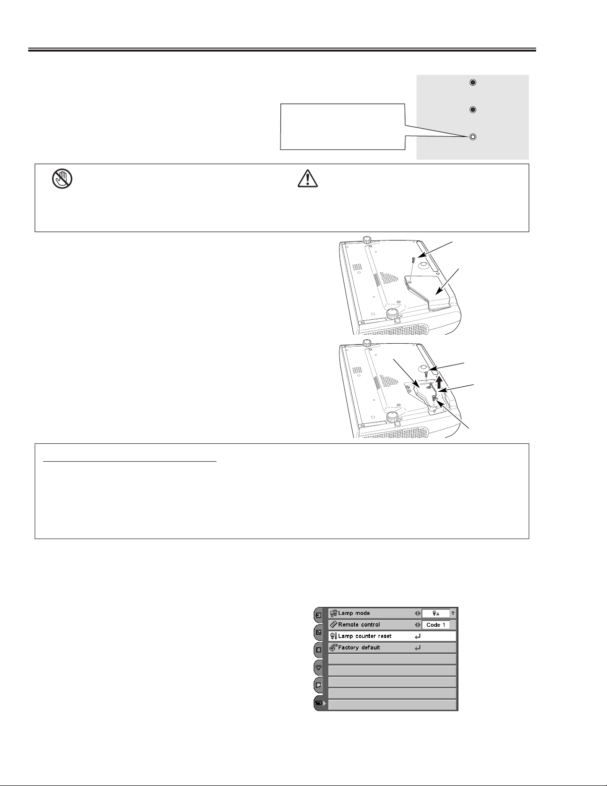
When the life of the projection lamp of this projector draws to
an end, the LAMP REPLACE indicator lights yellow. If this
indicator lights yellow, replace the lamp with a new one
promptly.
Follow these steps to replace the lamp.
Lamp
Lamp Cover
ORDER REPLACEMENT LAMP
Replacement lamp can be ordered through your dealer. When ordering a projection lamp, give the following information
to the dealer.
● Model No. of your projector : PLV-Z2
● Replacement Lamp Type No. : POA-LMP69
(Service Parts No. 610 309 7589)
For continued safety, replace with a lamp of the same
type. Do not drop a lamp or touch a glass bulb! The
glass can shatter and may cause injury.
Allow a projector to cool, for at least 45 minutes before
you open the Lamp cover. The inside of the projector
can become very hot.
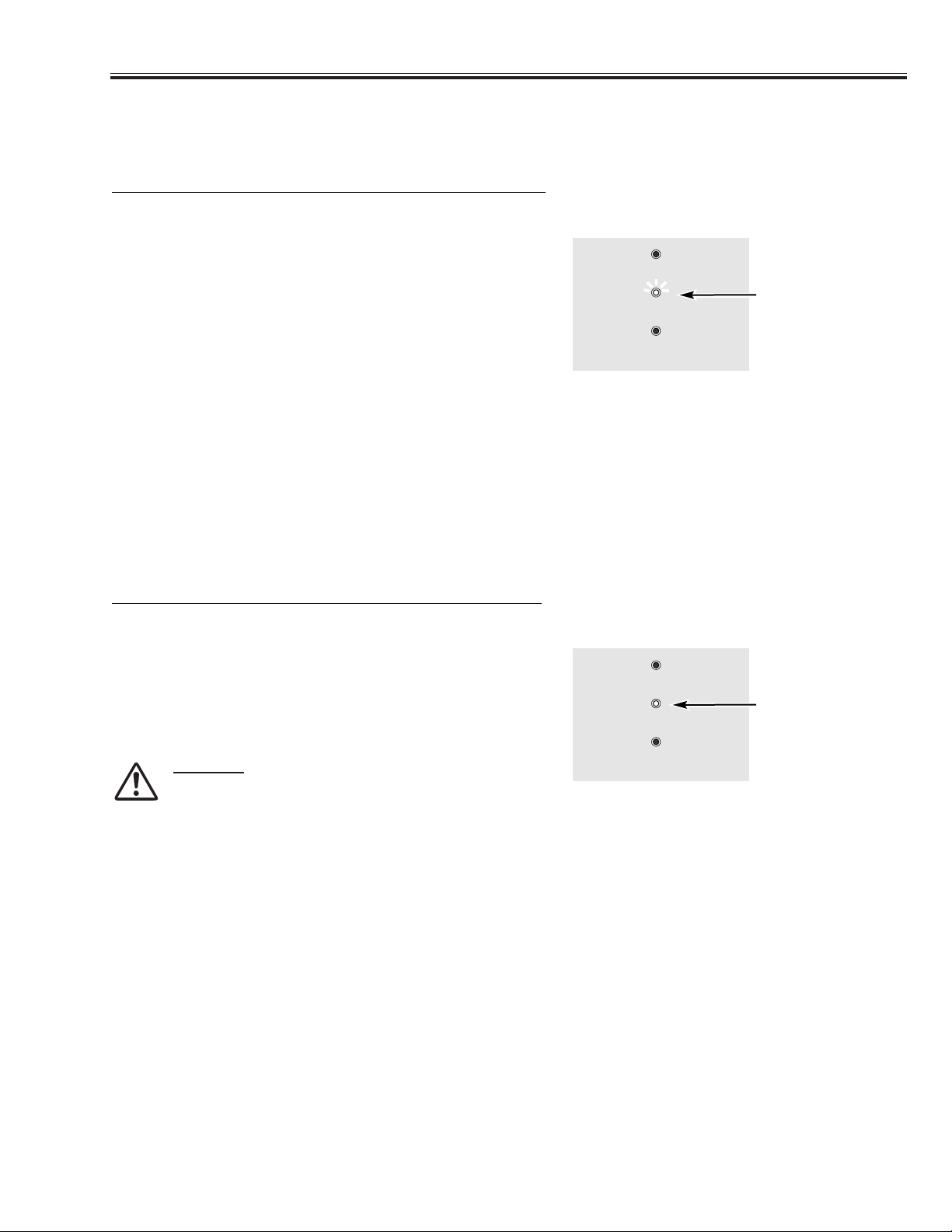
This indicator lights yellow
when the life of the projection
lamp draws to an end.
Top Control
CAUTION
Screw
Turn off the projector and disconnect the AC plug. Allow the
projector to cool for at least 45 minutes.
Loosen 2 screws of the lamp with a screwdriver and pull out the
lamp by grasping the handle.
1
3
Replace the lamp with a new one and tighten the 2 screws back
into position. Make sure that the lamp is set properly. Replace
the lamp cover and tighten the screw.
4
Turn over the projector. Loosen the screw with a screwdriver,
and remove the lamp cover.
2
Connect the AC power cord to the projector and turn on the
projector.
6
Reset the Lamp replace counter.
See “Lamp Replace Counter” on the next page .
5
Handle
CAUTION
Be sure to reset the lamp replace counter after the lamp is replaced. When the lamp replace counter is reset, the LAMP
REPLACE indicator stops lighting.
Turn the projector on, press the MENU button, and the OnScreen Menu will appear. Select the Setting Menu with the
Point Up/Down button and press the Point Right button to
enter the sub-menu.
Select the Lamp counter reset item and then press the
SELECT button. The message "Lamp replace counter
Reset?" is displayed. Choose [Yes] and then press the
SELECT button.
1
2
Another confirmation dialog box appears and choose [Yes] to
reset the Lamp replace counter.
3
NOTE
● Do not reset the Lamp replace counter without implementation of lamp replacement. Be sure to reset the Lamp
replace counter only after replacing the lamp.
Lamp counter reset
POWER
WARNING
LAMP
REPLACE
Page 5
-5-
■
Lamp Replacement
This projector uses a high-pressure lamp which must be handled carefully and properly. Improper
handling may result in accidents, injury, or create a fire hazard.
● Lamp lifetime may differ from lamp to lamp and according to the environment of use. There is no
guarantee of the same lifetime for each lamp. Some lamps may fail or terminate their lifetime in a
shorter period of time than other similar lamps.
● If the projector indicates that the lamp should be replaced, i.e., if the LAMP REPLACE indicator lights
up, replace the lamp with a new one IMMEDIATELY after the projector has cooled down.
( Follow carefully the instructions in the Lamp Replacement section of this manual. ) Continuous use
of the lamp with the LAMP REPLACE indicator lighted may increase the risk of lamp explosion.
● A Lamp may explode as a result of vibration, shock or degradation as a result of hours of use as its
lifetime draws to an end. Risk of explosion may differ according to the environment or conditions in
which the projector and lamp are being used.
IF A LAMP EXPLODES, THE FOLLOWING SAFETY PRECAUTIONS SHOULD BE TAKEN.
If a lamp explodes, disconnect the projector’s AC plug from the AC outlet immediately. Contact an
authorized service station for a checkup of the unit and replacement of the lamp. Additionally, check
carefully to ensure that there are no broken shards or pieces of glass around the projector or coming out
from the cooling air circulation holes. Any broken shards found should be cleaned up carefully. No one
should check the inside of the projector except those who are authorized trained technicians and who are
familiar with projector service. Inappropriate attempts to service the unit by anyone, especially those who
are not appropriately trained to do so, may result in an accident or injury caused by pieces of broken
glass.
LAMP HANDLING PRECAUTIONS
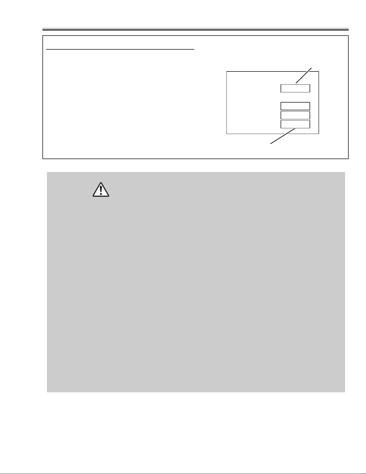
The LAMP REPLACE indicator will light when the total
lamp used time reaches 3,000 hours. This is to indicate that lamp replacement is required.
The total lamp used time is calculated by using the
below expression;
Total lamp used time = Teco + Tnormal x (1.5)
Teco: used time in the Eco mode
Tnormal: used time in the Eco mode
You can check the lamp replace counter following to
below procedure.
1 Press and hold the POWER ON-OFF button on the
projector or the remote control unit for more than 20
seconds.
2 The projector used time and lamp used time will be
displayed on the screen briefly.
How to check lamp used time
Total lamp used time
Projector used time
Counter
Projector 525H
Lamp
Normal 100H
Eco 375H
Total 525H
Page 6
-6-
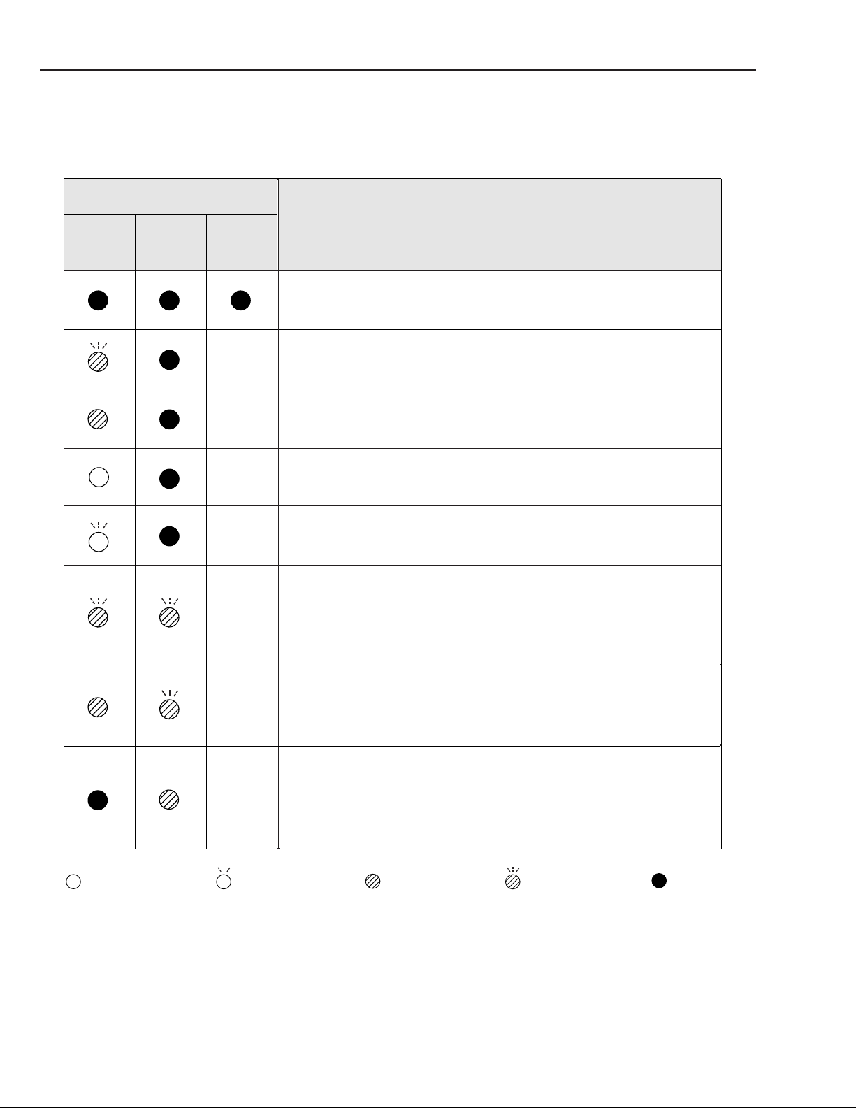
■ Indicators and Projector Condition
Check the Indicators for projector condition.
■
Indicators and Projector Condition
• • • lights green. • • • lights red.
• • • off
• • • flashes green.
✽ When the life of the projection lamp draws to an end, the LAMP REPLACE indicator lights yellow. When this indicator lights yellow,
replace the projection lamp with a new one promptly. Reset the Lamp replace counter after replacement of the lamp.
The Main On/Off switch is off or the AC power cord is unplugged.
The projector is preparing for stand-by and the front cover is closed. Or the
projection lamp is being cooled down. The projector cannot be turned on
until cooling is completed.
The temperature inside the projector is abnormally high. The projector cannot be turned on. When the projector is cooled down enough and the temperature returns to normal, the POWER indicator lights red and the projector can be turned on. (The WARNING . indicator keeps flashing.) Check
and clean the Air filter.
Projector Condition
The projector is ready to be turned on with the POWER ON-OFF button.
POWER
red/green
Indicators
LAMP
REPLACE
yellow
WARNING
red
The projector detects an abnormal condition and cannot be turned on.
Unplug the AC power cord and plug it again to turn on the projector. If the
projector is turned off again, disconnect the AC power cord and contact the
dealer or the service center for service and checkup. Do not leave the projector on. It may cause electric shock or a fire hazard.
✽
✽
✽
✽
✽
The projector is operating normally.
The projector is in the Power management mode.
✽
✽
The projector has been cooled down enough and the temperature returns to
normal. When turning on the projector, the WARNING indicator stops
flashing. Check and clean the air filter.
• • • flashes red.
Page 7
-7-
■ Warning Indicator
■
Warning Indicator
The WARNING indicator shows the state of the function which protects the projector. Check the state of the WARNING
indicator and the POWER indicator to take proper maintenance.
WARNING
flashing red
TOP CONTROL
The projector is shut down and the WARNING indicator is flashing red
When the temperature inside the projector exceeds the normal
temperature, the projector is automatically shut down to protect the
inside of the projector. The POWER indicator is flashing and the
projector is being cooled down. When the temperature inside the
projector returns to normal, the POWER indicator lights red and the
projector can be turned on.
NOTE
● After the temperature inside the projector returns to normal, the WARNING
indicator still continues to flash. When the projector is turned on again, the
WARNING indicator stops flashing.
Then check the items below.
✓ Did you provide appropriate space for the projector to be
ventilated? Check the installing condition to see if ventilation slots
are not blocked.
✓ Is the projector not installed near the ventilation duct of air-
conditioning equipment which may be hot? Install the projector
away from the ventilation duct of air-conditioning equipment.
✓ Is the air filter clean? Clean the air filter or replace it with a new
one.
TOP CONTROL
The projector is shut down and the WARNING indicator lights red
When the projector detects an abnormal condition, it is automatically
shut down to protect the inside and the WARNING indicator lights red.
In this case, disconnect the AC power cord and reconnect it, and then
turn the projector on once again for check. If the projector is turned off
again and the WARNING indicator lights red, disconnect the AC power
cord and contact the service station for check and repair.
CAUTION
DO NOT LEAVE THE PROJECTOR WITH THE AC
POWER CORD CONNECTED UNDER THE ABNORMAL
CONDITION. IT MAY RESULT IN FIRE OR ELECTRIC
SHOCK.
WARNING
lights red
POWER
WARNING
LAMP
REPLACE
POWER
WARNING
LAMP
REPLACE
Page 8
-8-
■ Cleaning
■
Cleaning the Air Filter
■
Replacing the Air Filter
Latch
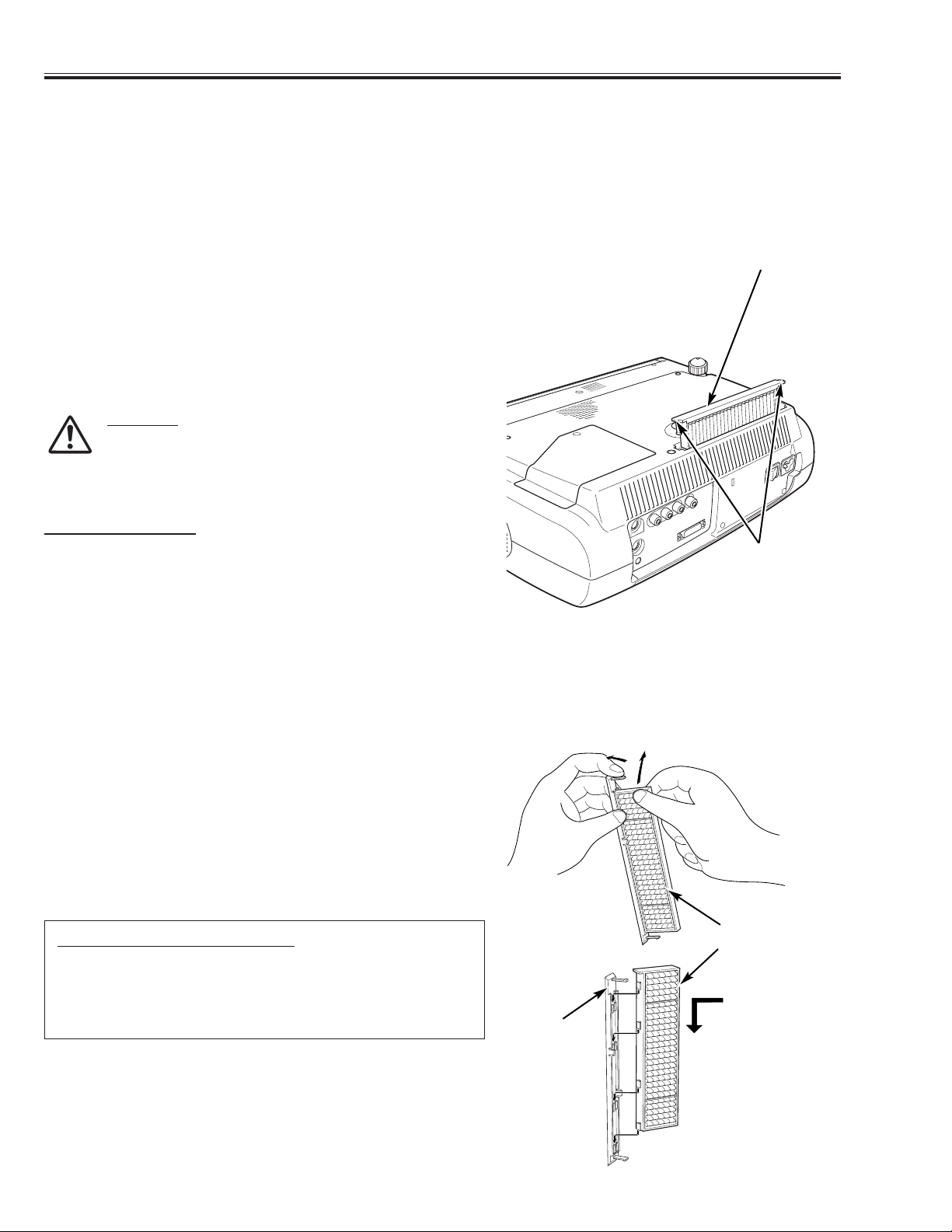
Turn off the projector and disconnect the AC power cord from
the AC outlet.
Turn over the projector and remove the air filter by pulling the
latches on both edges upward.
1
2
The air filter prevents dust from accumulating on the surface of the optical elements inside the projector. Should the air filter
become clogged with dust particles, it will reduce cooling fans’ effectiveness and may result in internal heat build up and
adversely affect the life of the projector. Clean the air filter following the steps below.
Remove dust and dirt with a soft brush. Be careful not to
damage the air filter and do not clean the air filter with water.
When there is much dust and dirt on the air filter, replace it with
a new one. (See below for replacing the air filter.)
3
Put the air filter back into position. Make sure that the air filter is
properly and fully inserted.
4
CAUTION
Do not operate the projector with the air filter removed. Dust
may accumulate on the LCD panel and the projection mirror
degrading picture quality.
Do not put small parts into the air intake vents. It may result
in malfunction of the projector.
RECOMMENDATION
We recommend avoiding dusty/smoky environments when operating
the projector. When using under dusty or smoky conditions, dust may
accumulate on a lens, LCD panels, or optical elements inside the
projector. This condition may degrade the quality of a projected
image.
When the above symptoms are noticed, contact your authorized
dealer or service station for proper cleaning.
Air Filter
After removing the air filter from the projector as described
above, remove the replacement filter from the holder.
Holds the air filter with both hands, and remove the replacement
filter by pulling it up.
1
2
When there is much dust and dirt on the air filter, replace it with a new one following the steps below.
Install a new replacement filter and put the air filter back into the
projector.
3
Replacement Filter
ORDER REPLACEMENT FILTER
Replacement filter can be ordered through your dealer or service
station.
● Replacement Filter Part No. : 610 312 0249
Install the replacement filter securely.
Remove the
replacement filter as
shown this figure.
Holder
Page 9
-9-
■
Cleaning
■
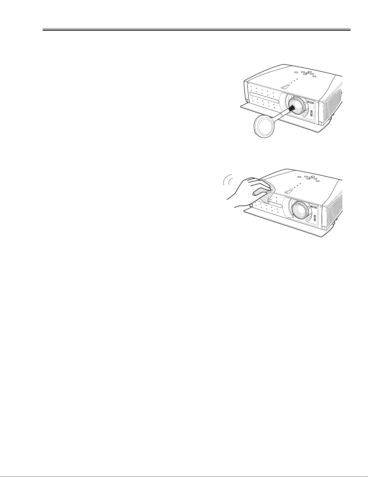
Cleaning the Projection Lens
■
Cleaning the Projection Cabinet
Disconnect the AC power cord before cleaning.
When the projector is not in use, replace the lens cover.
1
3
2
Follow these steps to clean the projection lens.
Softly wipe the projection lens with a cleaning cloth that contains
a small amount of non-abrasive camera lens cleaner, or use lens
cleaning paper or a commercially available air blower to clean
the lens. Avoid using an excessive amount of cleaner. Abrasive
cleaners, solvents, or other harsh chemicals might scratch the
surface.
Disconnect the AC power cord before cleaning.
1
Softly wipe the projector body with a soft, dry cleaning cloth.
When it is heavily soiled, use a small amount of mild detergent
and finish with a soft, dry cleaning cloth. Avoid using an
excessive amount of cleaner. Abrasive cleaners, solvents, or
other harsh chemicals might scratch the surface.
2
Follow these steps to clean the projector cabinet.
When the projector is not in use, put the projector in the carrying
case to protect it from dust and scratches.
3
Page 10
-10-
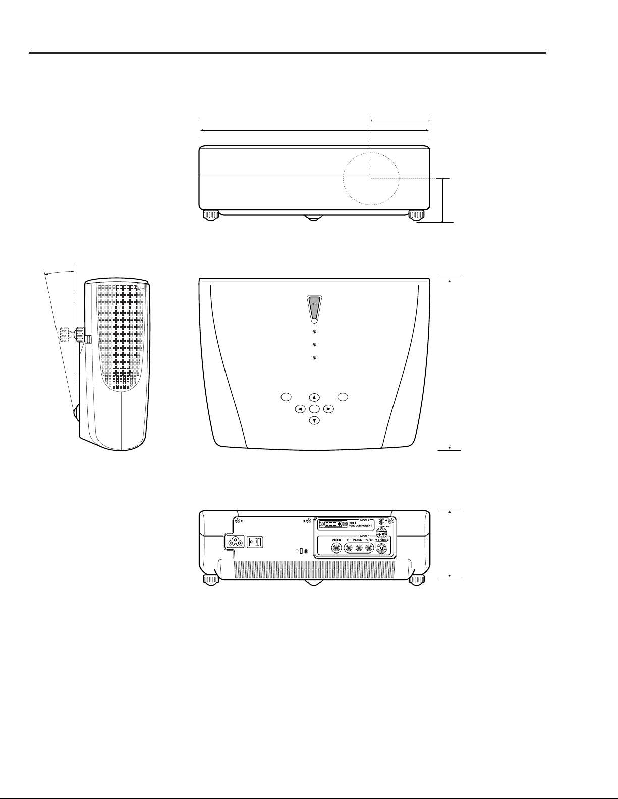
■ Dimensions
■
Dimensions
14.13 (359)
10.79 (274)
Unit : inch (mm)
11.8˚ (Max.)
3.82 (97)
4.52 (114.7)
2.68 (68)
ON-OFF
MENU
POWER
WARNING
LAMP
REPLACE
SELECT
INPUT
Page 11
-11-
■ Protections
This projector is equipped with the following protections to operate in safety. If the abnormality occurs
inside the projector, it will turn off the projector by operating one of the following protections.
■
FUSE FOR CIRCUIT PROTECTION
The fuse is located on the ass'y-Inlet. When either the
LAMP indicator or the READY indicator is not illuminated,
fuse may be opened. Check the fuse as following steps.
1. Remove the ass'y-Inlet following to “Mechanical
Disassemblies”.
2. Remove the fuse from fuse holder.
3. Check the resistance of fuse by using the tester.
To install the fuse, take reversed step in the above.
It should be used the specified fuse as parts list.
■
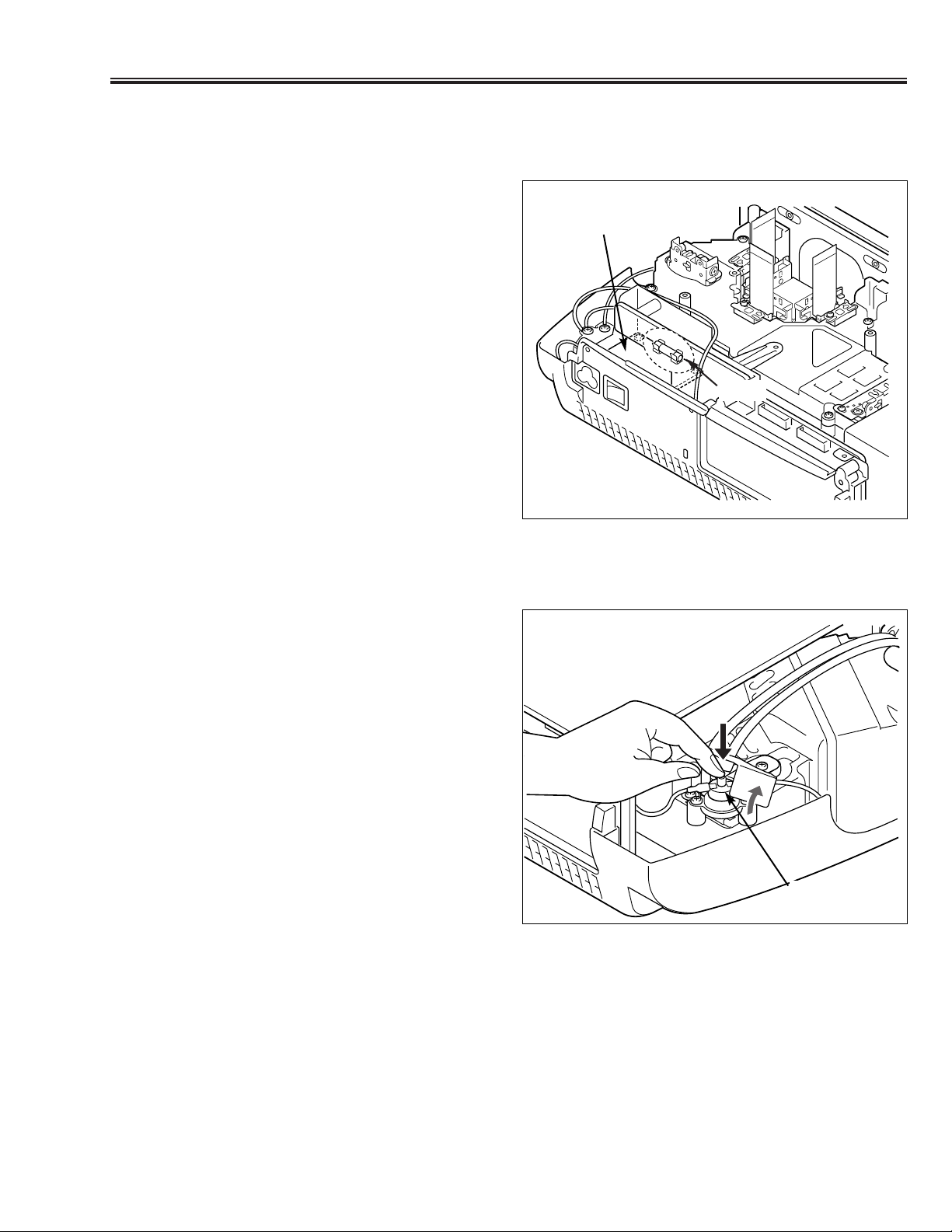
OVERHEATING PROTECTION
(The temperature monitor system )
The temperature monitor system is provided to prevents damage of component parts inside the projector from overheat.
■ Thermostat Switch: SW902
This function (thermostat switch SW902) will not operate,
while the temperature monitor is operating normally. If it
has operated, it needs to be reset manually. Disconnect
the AC cord first and investigate the cause of overheating.
After servicing, reset the thermostat switch (SW902) as
shown in a figure.
Fuse
Ass’y Inlet
SW902
Page 12

-12-
■ Mechanical Disassemblies
1. CABINET - TOP REMOVAL
1. Remove 6 screws to take the Cabinet Top upward off.
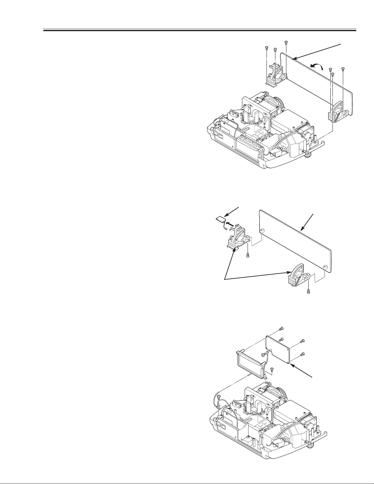
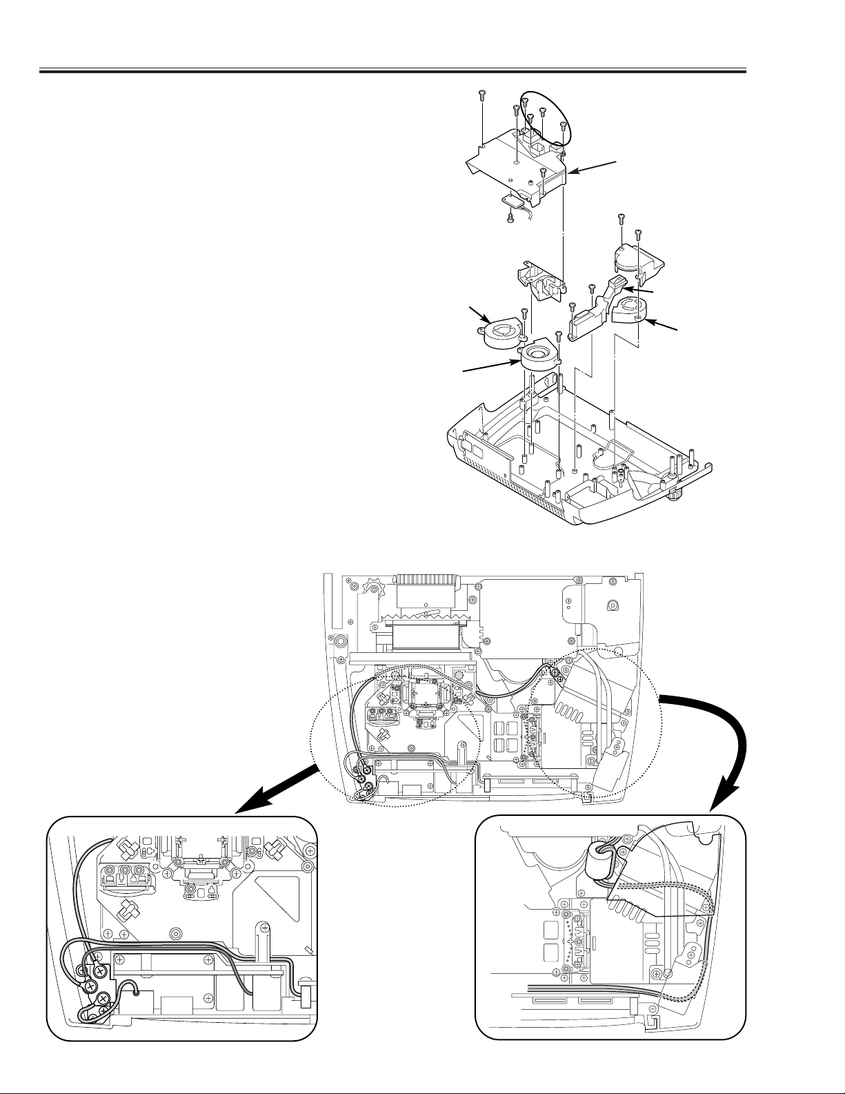
3. MAIN BOARD AND THERMAL BARRIER PLATE REMOVAL
1. Remove 7 screws A to take the Main Board upward off.
2. Remove 2 screws B to take the thermal barrier plate
upward off.
Fig. 1
Fig. 3
A
A
A
A
A
A
B
Main Board
Thermal
Barrier
Plate
2. CABINET - FRONT REMOVAL
1. Open the door.
2. Remove a screw to take the Cabinet Front off.
Fig. 2
Cabinet Top
Cabinet Front
Door
[Attention] This LCD projector is used the different kind of screw. The using correct screw is needed to prevent
the damage.
Note: For fixing the Cabinet Top, its
rib should be located in front of
the spacer lens.
Rib
Spacer
Lens
A
B
Page 13
-13-
■ Mechanical Disassemblies
4. DOOR ASS'Y REMOVAL
1. Remove 6 screws to take the Door Ass'y off.
Note: Can be removed Door itself. See below.
5. DOOR LEG AND DOOR SWITCH BOARD REMOVAL
1. Remove a screw to take each leg off.
2. Slide the Door Switch Board out.
Fig. 4
Door Ass'y
Door
Door Switch Board
Door Leg
Fig. 5
6. AV BOARD REMOVAL
1. Remove 2 screws A to take the AV Ass'y (Board with
Panel) upward off.
2. Remove 4 screws B to take the AV Board off from the
AV Panel.
AV Board
Fig. 6
AV Panel
B
A
A
B
B
B
Page 14
-14-
■ Mechanical Disassemblies
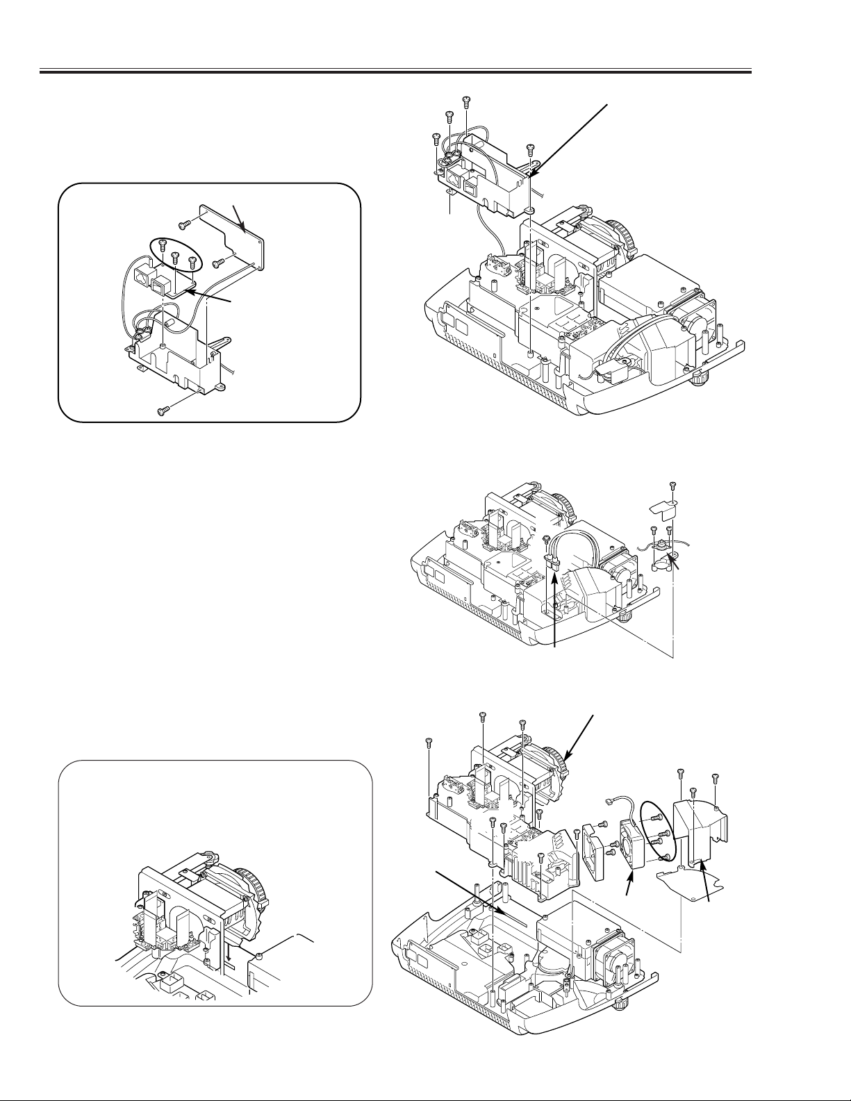
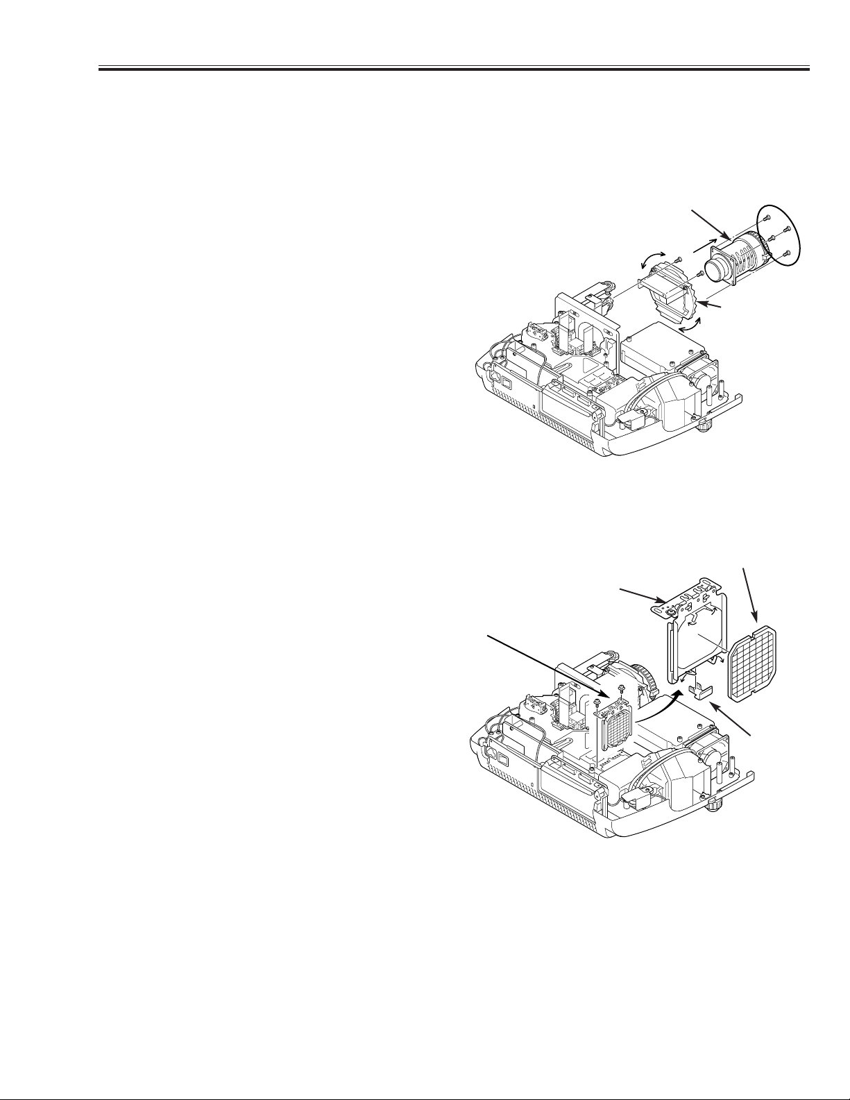
7. LAMP BALLAST UNIT REMOVAL
1. Remove 4 screws A to take the Filter Holder off.
2. Remove 3 screws B to take the Filter Board off.
3. Remove 3 screws C to take the Inlet Board off.
Filter Board
Fig. 7-1
A
A
A
A
B
B
B
C
Filter Holder
8. OPTICAL UNIT AND FAN REMOVAL
1. Remove a screw A to take the Thermostat Switch
upward off.
2. Remove a screw B to take the Lamp Socket off.
3. Remove 3 screws C to take the Fan Cover off.
4. Remove 8 screws D to take the Optical Unit off.
5. Remove 4 screws E to take the Fan (FAN903) off.
Fig. 8-1
Thermostat
Switch
A
B
C
C
D
D
Lamp Socket
FN903
Inlet Board
Fig. 7-2
Fan
Cover
C
E
Rib
Fig. 8-2
Spacer
Lens
D
D
D
D
D
D
Note: For fixing the Optical Unit, Spacer
Lens should be located in front of
the rib of Cabinet Bottom.
Fig. 8-3
Page 15
-15-
■ Mechanical Disassemblies
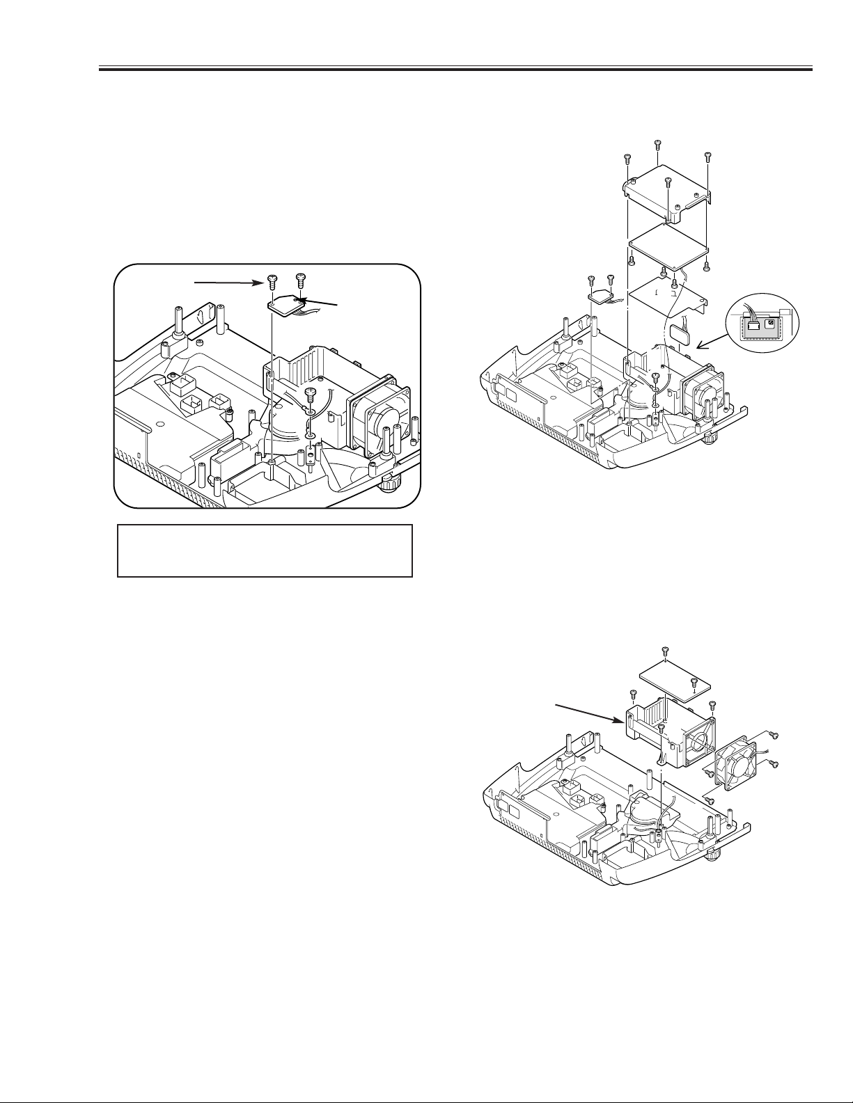
9. POWER BOARD REMOVAL
1. Remove 2 screws A to take the Lamp SW Board off.
2. Remove a screw B and 4 screws C to open the Power
Board Cover and take the R/C Board off.
3. Remove 4 screws D to take the Power Board off.
Note: For fixing Lamp SW Board, insert the guide to the
guide hole of Lamp SW Board and fix the screw of
below figure in the beginning.
Fig. 9
D
R/C Board
D
B
C
C
D
A
C
C
Guide Hole
10. LAMP BALLAST AND FAN REMOVAL
1. Remove 2 screws A to take the Lamp Ballast Unit
upward off.
2. Remove 3 screws B to take the Power Board Holder
off.
3. Remove 4 screws
C to take the Fan (FN901) off.
Fig. 10
A
A
C
B
B
B
C
Lamp Ballast
FN901
Power Board
Power Board
Cover
Lamp SW Board
A
D
Fix in the
beginning.
Power Board
Holder
C
C
Note: Remove the Lamp Cover before fixing the
Lamp SW board to prevent the damage of
Lamp SW board.
Page 16
-16-
■ Mechanical Disassemblies
11. FANS REMOVAL
1. Remove 2 screws A and 5 screws B to take the Fan
Cover off.
2. Remove a screw C to take the Sensor Board off from
tha Fan Cover.
3. Remove 2 screws D to take the Duct Cover-A off.
4. Remove 2 screws E to take the Duct Cover-B and Fan
(FN902) off.
5. Remove a screw F to take Fan (FN904) or Fan (FN905)
off.
Fig. 11
D
Fan Cover
E
E
A
C
A
D
B
B
FN904
FN902
F
F
Sensor Board
Duct Cover-A
Duct
Duct Cover-B
FN905
12. DRESSING GROUNDING WIRE
The grounding wires should be dressed
as below figure.
Page 17
-17-
■ Optical Parts Disassemblies
Before Taking this procedure, remove Cabinet Top and Main board following to the “Mechanical
Disassemblies”.
Disassembly requires a 2.0mm hex wrench and a screwdriver.
1. PROJECTION LENS REMOVAL
1. Remove 2 screws A to slide the Lens Spacer and
remove 4 screws B to take the Projection Lens off.
Fig. 1
Projection Lens
Lens Spacer
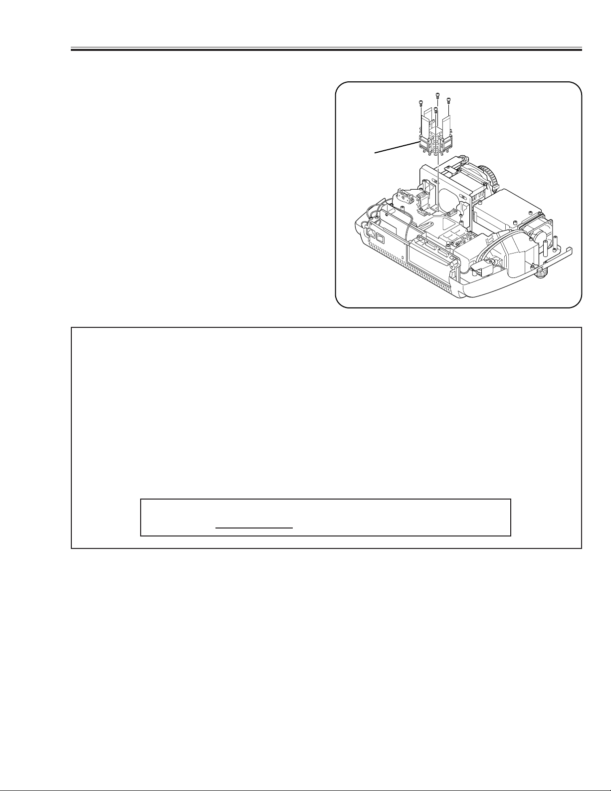
2. INTEGRATOR LENS REMOVAL
1. Remove 2 screws and pull the Integrator Lens Ass’y
upward.
2. Remove the Stopper and bend four hooks and then
take the Lens off from the Holder.
Integrator Lens
Stopper
Lens Holder
Fig. 2
Integrator Lens Ass’y
Note:
Should be placed the lens as the rugged surface side
of it comes to the holder side.
A
A
B
Page 18
-18-
■ Optical Parts Disassemblies
3. RELAY LENS REMOVAL
1. Remove 2 screws A and pull the Relay Lens Ass’y
upward.
2. Remove 2 screws B to take the Lens off from the
Holder.
Relay Lens
Relay Lens Ass’y
Fig. 3
A
B
A
B
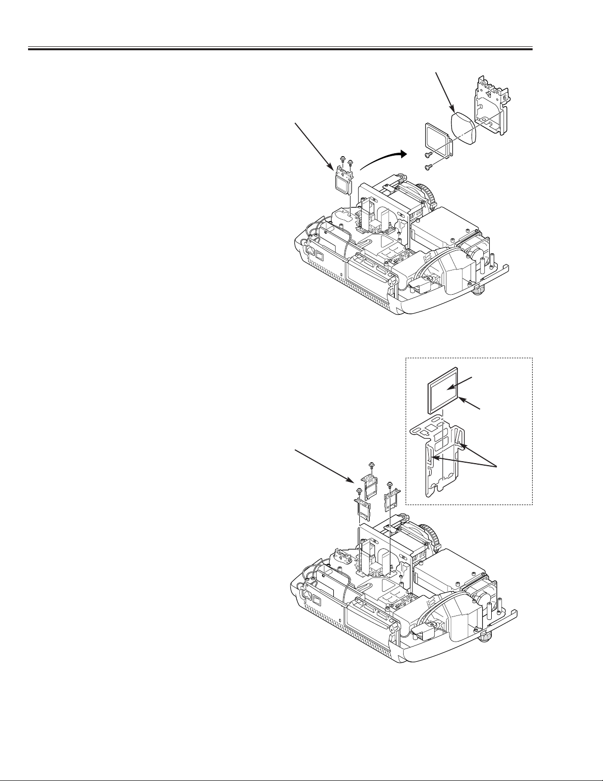
4. POLARIZED GLASS-IN REMOVAL
1. Remove each screw and pull the Polarized Glass-In
Ass’y upward.
2. Unhook the stoppers and take the glass off upward.
Polarized Grass Ass’y
Polarized
Grass-In
Phase Sheet
Hook
Note:
Should be placed the glass as the film attached side
come to the prism side.
Fig. 4
Page 19
-19-
■ Optical Parts Disassemblies
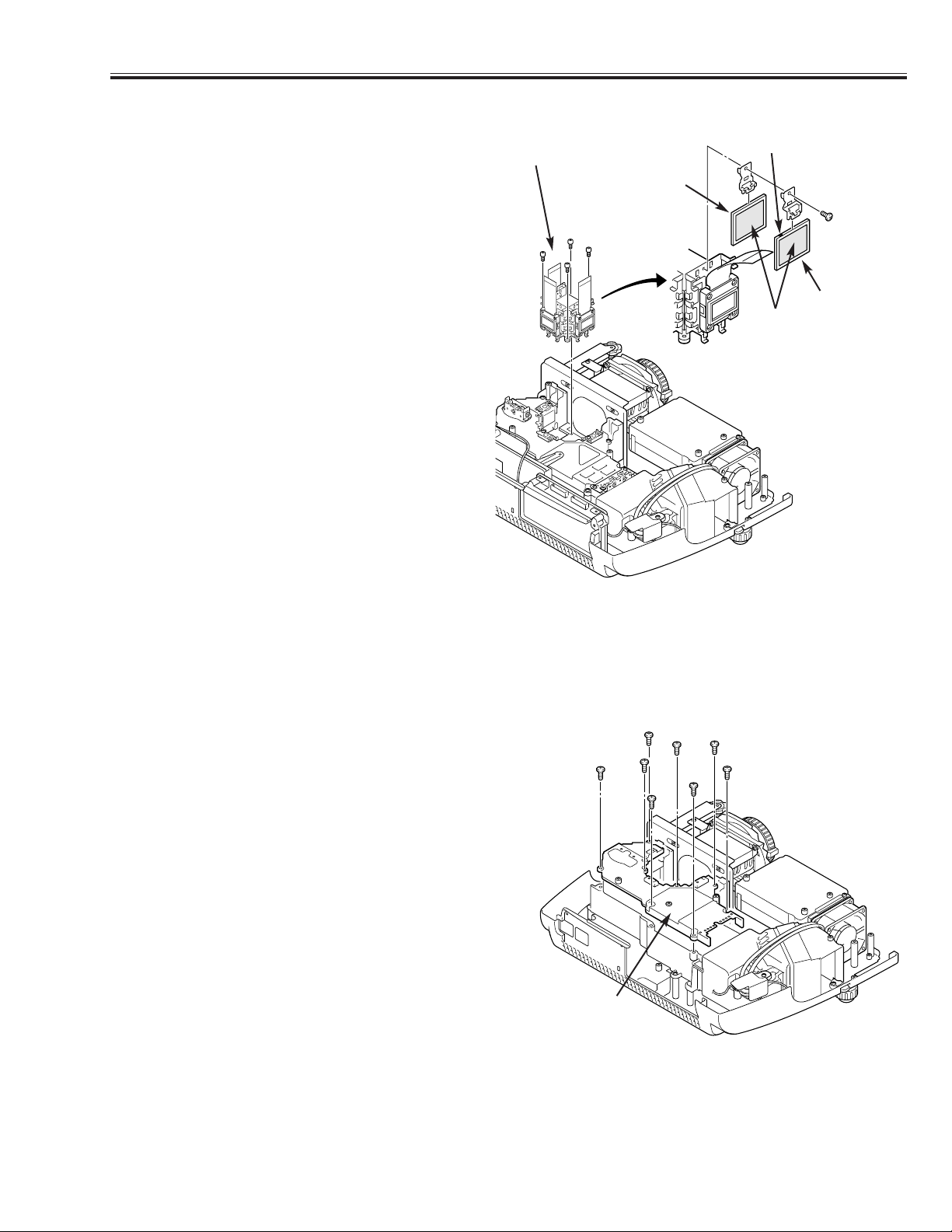
5. POLARIZED GLASS-OUT AND WIDE VIEW PLATE REMOVAL
1. Remove 4 screw A and take the LCD Panel/Prism
Ass’y upward from the Optical Unit.
2. Remove each screw B and take the glass off upward.
LCD Panel/Prism Ass’y
Note:
1.
Fix the plate that the mark is located to left and
upper.
R,G: Red marking, B: Blue marking
2. Should be replaced the glass as the film attached
side comes to the LCD panel side.
Fig. 5
Polarized
Grass-Out
Film
Note 2
A
A
A
A
B
6. OPTICAL UNIT TOP REMOVAL
1. Remove Cabinet Top, Cabinet Front, Main Board, AV
Board and Filter Ass'y.
2. Remove 8 screws to take the Optical Unit Top off
upward.
Fig. 6
Wide View
Plate
Note 1
Optical Unit
Top
Page 20
-20-
■ Optical Parts Disassemblies
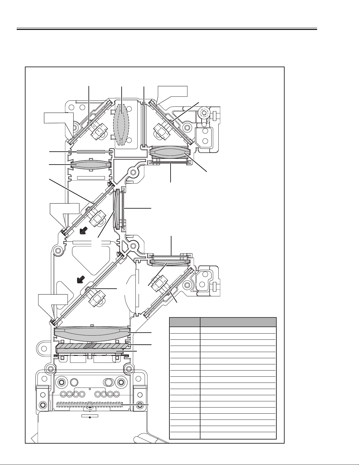
7. LOCATIONS IN OPTICAL UNIT
When mounting or assembling the optical parts in the optical unit, the parts must be mounted specified location as shown
in figure below.
6
1
2
3
4
5
7
8
9
10
11
11
12
13
15
14
16
17
18
Marking
Marking
Cut Face
Cut Face
1 Lens (Condenser G)
2 Lens (Condenser R)
3 Prism Beam Splitter (PBS)
4 Condenser Lens (Out)
5 Condenser Lens (B)
6 Relay Lens (In)
7 Relay Lens (Out)
8Integrater Lens (In)
9Integrater Lens (Out)
10 Mirror (R)
11 Mirror (B)
12 Optical Filter (R, G)
13 Optical Filter (UV Cut)
14 Polarized Grass (IN/R)
15 Polarized Grass (IN/B)
16 Polarized Grass (IN/G)
17 Di-chroic Mirror (G)
18 Di-chroic Mirror (R)
Key No. Description
Page 21
-21-
■ LCD Panel/Prism Ass'y Replacement
1. LCD PANEL/PRISM ASS'Y REMOVAL
1. Remove Cabinet Top and Main Board.
2. Remove 4 screws by a 2.0mm hex wrench to take the
Panel/Prism Ass'y off from the Optical Unit.
Note: Do not replace the LCD panel separately other-
wise it can not obtain proper picture. Do not
touch the prism, the LCD panel and the electrode of flexible cable.
IMPORTANT NOTICE on LCD Panel/Prism Ass'y Replacement
LCD panels used for this model can not be replaced separately. Do not disassemble the LCD Panel/Prism Ass’y.
These LCD panels are installed with precision at the factory. When replacing the LCD panel, should be replaced
whole of the LCD panels and prism ass’y at once.
After replacing LCD Panel/Prism ass’y, please check the following adjustments.
- Check the “Condenser Lens Adjustment” and “Relay Lens Adjustment” following to chapter “Optical
Adjustment”.
- Check the “White Balance Adjustment” and “Common Centre Adjustment” following to chapter
“Electrical Adjustment”.
- Check the white uniformity on the screen.
If you find the color shading, please adjust the white uniformity by using the proper computer and “Color
Shading Correction” software supplied separately. The software can be ordered as follows;
COLOR SHADING CORRECTION
Service Parts No. 645 056 6288 or 645 066 7428
1. Tighten 4 screws by a 2.0mm hex wrench to fix the
Panel/Prism Ass'y to the Optical Unit.
2. LCD PANEL/PRISM ASS'Y ATTACHMENT
LCD
Panel/Prism
Ass'y
Page 22
-22-
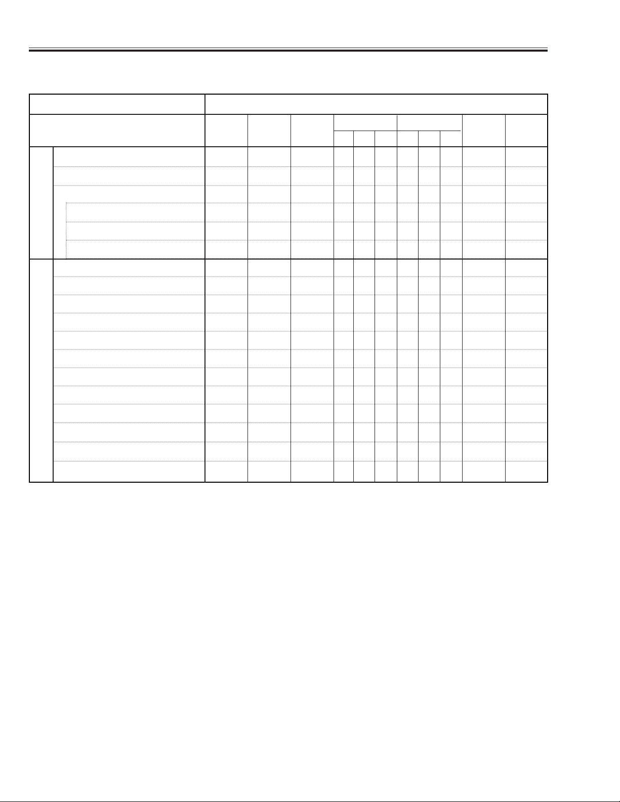
■ Adjustments After Parts Replacement
● : Adjustment necessary ❍ : Check necessary
Condenser Lens Adjustment ❍●
Relay Lens Adjustment ❍●
Contrast Adjustment
R-Contrast adjustment ❍●●
G-Contrast adjustment ❍●●
B-Contrast adjustment ❍●●
Fan Minimum Adjustment ●●
Signal Center Adjustment ●
Reference Adjustment ●
PC Pedestal Adjustment ●
PC Gain Adjustment ●
480p Pedestal Adjustment ●
480p Gain Adjustment ●
480i Gain Adjustment ●
Video Gain Adjustment ●
Common Voltage Adjustment ●●
50% Luminance Adjustment ●●
White Balance Adjustment ❍●
Disassembly / Replaced Parts
LCD/
Prism
Ass’y
Condenser
Lens
Polarized glass
RGB
Optical Adjustments
Electrical Adjustments
Main
Board
Relay
Lens
Power
Board
Wide View
RGB
Page 23
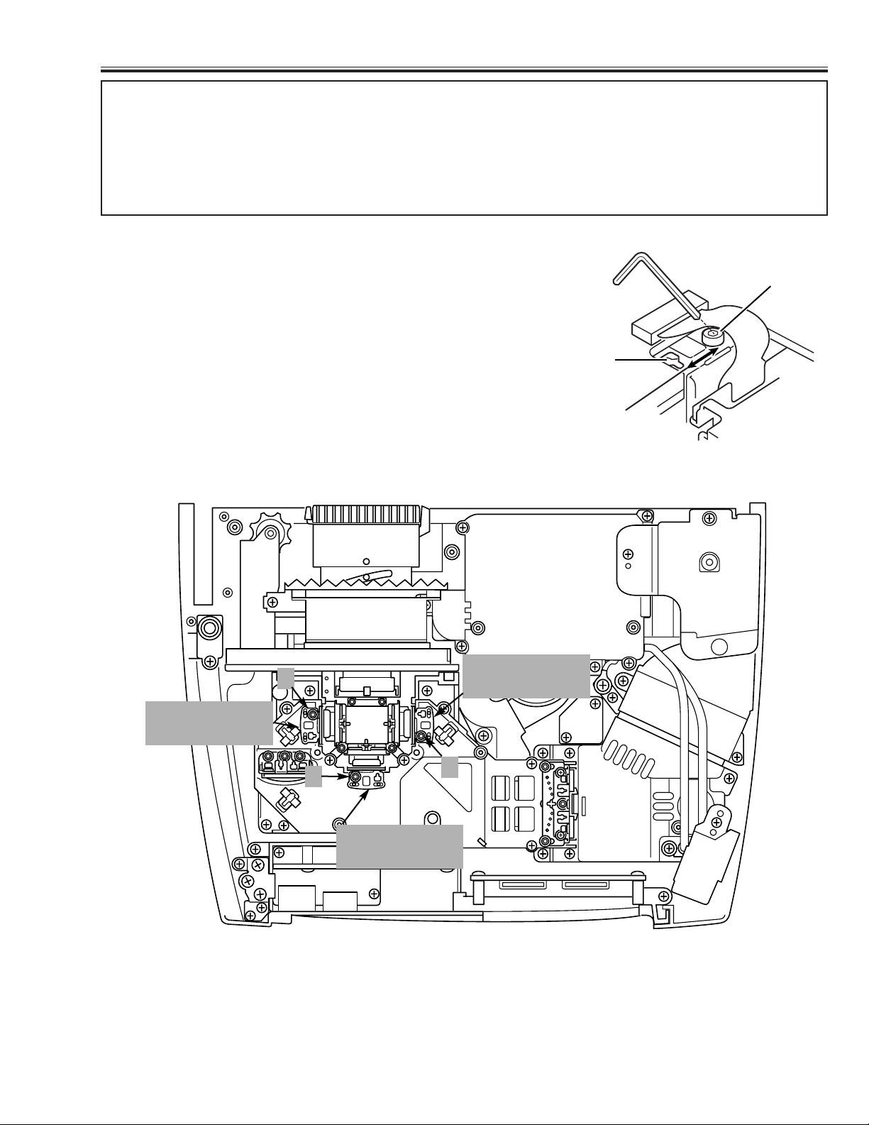
-23-
■ Optical Adjustment
Before taking optical adjustments below, remove the Cabinet Top and Main Board following to the “Mechanical
Disassemblies”
Adjustments require a 2.0mm hex wrench and a slot screwdriver. When you adjust Integrator lens or Relay lens
adjustment, you need to disconnect some connectors and FPC cables of LCD panels on the main board.
Note:
Do not disconnect connectors on the main board, because the projector can not turn on or operate properly for
adjustment.
[Before Adjustment]
- Input a 100% of black raster signal.
[R/G/B-CONTRAST ADJUSTMENT]
1. Loosen a screw A on the polarized glass mounting base which
you intend to adjust.
2. Turn the polarized glass mounting base as shown in Fig. 1 to
obtain the darkest brightness on the screen.
3. Tighten the screw A to fix the polarized glass mounting base.
Repeat steps 1 to 3 for remaining polarized glasses.
Slot B
Polarized Glass
Mounting Base
A
1. CONTRAST ADJUSTMENT
Fig. 1
B-Polarized Grass
Mounting Base
A
G-Polarized Grass
Mounting Base
A
R-Polarized Grass
Mounting Base
A
Fig. 2
Page 24

-24-
■ Optical Adjustment
1. Turn the projector on by a state of without FPC
cables.
2. Project all of lights on the screen.
3. Adjust the adjustment base of integrator lens ass’y
to make color uniformity in white.
2. INTEGRATOR ADJUSTMENT
Fig. 3
1. Turn the projector on by a state of without FPC
cables.
2. Project all of lights on the screen.
3. Adjust the adjustment base of relay lens ass’y to
make color uniformity in white.
3. RELAY ADJUSTMENT
Fig. 4
Page 25

-25-
■ Electrical Adjustment
■ SERVICE ADJUSTMENT MENU OPERATION
■ To enter service mode
To enter service mode press the "MENU" and "INPUT"
buttons on the projector simultaneously and hold for 2
seconds. As shown in a figure, a service mode display
appears on a screen.
■ Adjustment
Adjust service data using the following control buttons.
1. "POINT UP" ------- An item number increases.
2. "POINT DOWN" -- An item number decreases.
3. "POINT RIGHT" -- An adjustment value increases.
4. "POINT LEFT" ---- An adjustment value decreases.
■ To exit service mode
Press the "POWER on/off" button only once on the projec-
tor or remote control unit to quit the service mode.
IC1841 on the main board stores the data for the service adjustments, and should not be replaced except
for the case of defective device.
If replaced, it should be performed the re-adjustments
following to the “Electrical Adjustments”.
The data of lamp replacement monitor timer is stored
in the IC1841.
Please note that the lamp replace counter is reset
when the memory IC (IC1841) is replaced.
(Lamp replace counter can not be set to the previous
value.)
● Caution to memory IC replacement
When IC1841 is replaced with new one, the CPU
writes down the default data of the service adjustments to the replaced IC, refer to the service adjustment table. As these data are not the same data as
factory shipped data, it should be required to perform
the re-adjustments following to the “Electrical
Adjustments”.
Please note that in this case the lamp replace counter
will be reset.
● Caution of Main Board replacement (in the case
IC1841 is not defective)
When the main board is replaced, IC1841 should be
replaced with the one on previous main board. After
replacement, it should be required to perform the readjustments following to the “Electrical Adjustments”.
In this case, the lamp replace counter can be kept the
value as before.
■ MEMORY IC REPLACEMENT
Normal Mode Service Mode
"MENU"
"INPUT"
"POWER
ON/OFF"
Service Mode
Computer
"Point Up / Down"
Adjustment item Adjustment deta value
ON-OFF
Service Mode
Computer
13710
13710
"Point Left / Right"
POWER
WARNING
LAMP
REPLACE
MENU
INPUT
SELECT
Page 26

-26-
■ Adjustment
Caution :
Other adjustment items are not related to service and a maintenance. Don't press the POINT (L) and (R) button
at the time of those adjustment items. Otherwise it may cause loss of product safety.
■ ELECTRICAL ADJUSTMENTS
2. Signal Center Adjustment
Equipment Digital voltmeter.
Input mode Input 2 [RGB Analog]
Input Signal 16 step gray scale signal
Enter the Service mode.
Adjust below values of each test points by the POINT L or
R button.
Item no.
Test Point Adjustment value
1 TPV1R 6.5 ± 0.05 V-DC.
2 TPV1G 6.5 ± 0.05 V-DC.
3 TPV1B 6.5 ± 0.05 V-DC.
[Adjustment Condition]
● Input signal
Video signal .......................... 1.0Vp-p/75Ω terminated, 16 steps gray
scale, white 100% and white 50% pattern (Composite video signal)
Computer signal .................... 0.7Vp-p/75Ω terminated, 16 steps gray
scale pattern (SVGA)
Component Video signal........ 0.7Vp-p/75Ω terminated, 16 steps gray
scale, white 100% and black 0% pattern
(480i format and 480p format)
● Picture control mode ................ “STANDARD” mode unless otherwise
noted.
Note: Please refer to “Service Adjustment Menu Operation” for entering to the service mode and adjusting the ser-
vice data.
16 steps gray scale pattern
1. Fan Minimum Voltage Adjustment
Equipment Digital voltmeter
Adjustment Value 3.5 ± 0.05 V-DC
Enter the Service mode.
Adjust values of below items by the POINT L or R button.
Item no. Fan Location
Test Point
100 FN901 TPFAN1
101 FN902 TPFAN2
102 FN903 TPFAN3
103 FN904/5 TPFAN4
3. Reference Adjustment
Equipment Oscilloscope
Input mode Input 2 [RGB Analog]
Input Signal 16 step gray scale signal
Enter the Service mode.
Adjust the amplitude of part A to be below value for each
test point by the POINT L or R button.
Item no. Test Point Adjustment value
10 TP35R 10.0 ± 0.1 Vp-p
11 TP35G 10.0 ± 0.1 Vp-p
12 TP35B 10.0 ± 0.1 Vp-p
4. Pedestal Adjustment (PC & Component)
Equipment Oscilloscope
Input Signal 16 step gray scale signal
4-1 Input mode Input 2 [RGB Analog]
4-2 Input mode Input 2 [Component: 480p]
Enter the Service mode.
Adjust the level of Black and pedestal to be same for each
test point by the POINT L or R button
in each mode.
Item no. Test Point
203 TP35R
204 TP35G
205 TP35B
White 100%
Black 100%
A
PedestalLevel=BlackLevel
Page 27

-27-
■ Adjustment
5. Gain Adjustment
Equipment Oscilloscope
Input Signal 16 step gray scale signal
5-1 Input mode Input 2 [RGB Analog]
5-2 Input mode Input 2 [Component: 480p]
5-3 Input mode Input 2 [Component: 480i]
5-4 Input mode Input 1 [Video: NTSC]
Enter the Service mode.
Adjust below level “A” in each test point to be minimum
amplitude by the POINT L or R button in each mode.
Item no. Test Point
7 TP35R
8 TP35G
9 TP35B
7. 50% Luminance Adjustment
Input Signal 16 step gray scale signal
7-1 Input mode Input 2 [RGB Analog]
7-2 Input mode Input 2 [Component: 480p]
7-3 Input mode Input 2 [Component: 480i]
Enter the Service mode.
If the black or white saturated picture can be seen, adjust
the item "No.16" to be reduced it by the POINT L or R button.
6. Common Voltage Adjustment
Input mode Input 2 [RGB Analog]
Input Signal 1dot computer signal
Enter the Service mode.
Adjust to be minimum flicker for each color by the POINT L
or R button.
Item no. Screen
13 Only red color picture
14 Only green color picture
15 Only blue color picture
8. White Balance Adjustment
Input Signal 16 step gray scale signal
8-1 Input mode Input 2 [RGB Analog]
8-2 Input mode Input 2 [Component: 480p]
8-3 Input mode Input 2 [Component: 480i]
Enter the Service mode.
Adjust the item "No.17 (Red)" and "No.18 (Blue)" to be
good white balance by the POINT L or R button.
Note: The white balance of each mode must be same.
(9. Color Shading Correction)
For the color shading correction, the proper computer and
“ Color Shading Correction” software are needed.
The software can be ordered as follows.
COLOR SHADING CORRECTION
Service Parts No.
645 056 6288 or 645 066 7428
A
Page 28

-28-
■ Adjustment
1 R-VIDEOCNT ✻ 53 0-255
2 G-VIDEOCNT ✻ 53 0-255 Video Center Adjustment (= RGB - V1)
3 B-VIDEOCNT ✻ 53 0-255
4 R-SubBright 0 0 0 0 0 0 0-1023
5 G-SubBright 0 0 0 0 0 0 0-1023
6 B-SubBright 0 0 0 0 0 0 0-1023
7 R-SubGain ✻ 520 490 490 530 530 530 0-1023 Gain Adjustment [R]
8 G-SubGain ✻ 520 490 490 530 530 530 0-1023 Gain Adjustment [G]
9 B-SubGain ✻ 520 490 490 530 530 530 0-1023 Gain Adjustment [B]
10 REF-R 140 0-255
11 REF-G 140 0-255
12 REF-B 140 0-255
13 BVCOM ✻ 95 0-255
14 GVCOM ✻ 95 0-255 Common Center Adjustment
15 RVCOM ✻ 95 0-255
16 G-GammaShift ✻ 512 500 500 512 512 512 0-1023 Gamma Adjustment
17 R-GammaShift ✻ 512 500 500 512 512 512 0-1023 White Balance Adjustment [R]
18 B-GammaShift ✻ 512 500 500 512 512 512 0-1023 White Balance Adjustment [B]
21 R-V2 (86) 0-255 Link to No.1
22 G-V2 (86) 0-255 Link to No.2
23 B-V2 (86) 0-255 Link to No.3
24 SubBright 128 128 128 128 128 128 128 128 25 SubColor 96 95 95 95 95 26 SubTint 0 000028 SubBright(Video) 128 128 128 0-255
29 SubCont(Video) 55 55 56 0-63
30 SubColor(Video) 2070 2070 2070 0-4095
31 SubTint(Video) 512 512 0-1023
32 SubBright(480i,575i) 196 196 0-255
33 SubCont(480i,575i) 21 23 0-63
34 SubColor-Cb(480i,575i) 35 23 35 35 0-63 575i is linked to PAL
35 SubColor-Cr(480i,575i) 35 29 35 35 0-63 480i is linked to NTSC
36 SubTint(480i,575i) 32 32 32 0-63
37 YC Delay 62 62 62 62 0-63
38 SubSharpness 0039 V-Line Color Shading Correction <R1> 2 0-255
40 V-Line Color Shading Correction <R2> 1 0-255
41 V-Line Color Shading Correction <R3> 254 0-255
42 V-Line Color Shading Correction <G1> 2 0-255
43 V-Line Color Shading Correction <G2> 1 0-255
44 V-Line Color Shading Correction <G3> 254 0-255
45 V-Line Color Shading Correction <B1> 2 0-255
46 V-Line Color Shading Correction <B2> 1 0-255
47 V-Line Color Shading Correction <B3> 254 0-255
48 <R>Reference Voltage (H) 1016 0-1023
49 <R>Reference Voltage (L) 420 0-1023
50 <G>Reference Voltage (H) 1016 0-1023
51 <G>Reference Voltage (L) 420 0-1023
52 <B>Reference Voltage (H) 1016 0-1023
53 <B>Reference Voltage (L) 420 0-1023
54 55 Color Shading Correction ON/OFF 1 - V-Line Correction
56 LampLifeTime - Display Only
57 BauRate 1 - 0;9600/ 1;19200/ 2;38400
58 ShootOutMode 0 - 0;Normal/ 1;Shoot out1/ 2;Shoot out2
59 PC Frame Lock 0 - 0: Unlocked, 1: 45MHz-60.1MHz Locked
60 Forced NoBrand 0 - 0: Normal, 1: No Brand
AutoGrayScaleTune
70 White Controlled Starting Point 30 0-255
71 White Controlled Limit Point 61 0-255
72 White Controlled Starting Point 9 0-255
73 White Controlled Limit Point 1 0-255
FAN CONTROL
100 Fan1 Min Adjust ✻ 28 0-255 Fan Voltage: 3.5V Adjustment
101 Fan2 Min Adjust ✻ 28 0-255
102 Fan3 Min Adjust ✻ 28 0-255
103 Fan4 Min Adjust
✻ 28 0-255
Initial Detail
No. Name AD9882 Micronas Video Range Note: 480i(+) = 480i + 575i
PC DVI HDCP YPbPr YCbCr SCART NTSC PAL 480p(+) = 480p + HDTV
■ SERVICE ADJUSTMENT DATA TABLE
These initial values are the reference data written from the CPU ROM to
memory IC when replaced new memory IC. The adjustment items indicated with “
✻” are required to readjust following to the “Electrical
adjustments”. Other items should be used with the initial data value.
Page 29

-29-
■ Adjustment
104 Fan1 Max Adjust 185 0-255 Fan Voltage: 14.5V Adjustment
105 Fan2 Max Adjust 185 0-255
106 Fan3 Max Adjust 185 0-255
107 Fan4 Max Adjust 185 0-255
108 Fan Control Mode 0 0-4 0:Normal,1:Cell, 2:Wall, 3:H-Pressure, 4:Manual
109 Fan Max Min SW 0 0-2 0:Auto Fan Control,1:Min,2:Max
Normal Cell Wall H-Pre
110 Fan1 Min 80 80 80 85 30-145 Fan Minimum Voltage (Normal)
111 Fan2 Min 50 50 50 60 30-145
112 Fan3 Min 90 90 90 110 30-145
113 Fan4 Min 45 45 45 70 30-145
114 Fan1 Max 110 110 110 120 30-145 Fan Maximum Voltage (Normal)
115 Fan2 Max 95 95 95 95 30-145
116 Fan3 Max 132 132 132 132 30-145
117 Fan4 Max 135 135 135 135 30-145
118 TempA Low 30 30 30 29 10-100
119 TempA High 38 38 38 38 10-100
120 Eco Fan1 Min 55 55 55 85 30-145 Fan Minimum Voltage (Eco)
121 Eco Fan2 Min 35 35 35 55 30-145
122 Eco Fan3 Min 58 58 58 90 30-145
123 Eco Fan4 Min 35 35 35 60 30-145
124 Eco Fan1 Max 75 75 75 105 30-145 Fan Maximum Voltage (Eco)
125 Eco Fan2 Max 50 50 50 60 30-145
126 Eco Fan3 Max 90 90 90 100 30-145
127 Eco Fan4 Max 90 90 90 110 30-145
128 Eco TempA Low 30 30 30 29 10-100
129 Eco TempA High 38 38 38 38 10-100
130 TempA Error 43 44 44 40 10-100
131 TempB Error 80 80 80 80 10-100
132 TempC Error 54 54 55 45 10-100
133 TempB-A Error 50 50 50 33 10-100
134 TempC-A Error 32 32 32 20 10-100
135 TempB Low UP 63 10-100
136 TempB High Up 64 10-100
137 TempB Low Down 41 10-100
138 TempB High Down 42 10-100
139 Manual Fan1 Voltage 100 30-145 Fan Operating Voltage (Manual)
140 Manual Fan2 Voltage 100 30-145
141 Manual Fan3 Voltage 100 30-145
142 Manual Fan4 Voltage 100 30-145
143 Temp Error Cooling Time 3 0-15 0:Always,1:30s, 2:60s, /... /, 15:450s
144 Cooling Time 3 0-15 1:30s, 2:60s, 3:90s, /... /, 15:450s
145 average time 2 1-5
146 ECO LAMP TIME 147 NORMAL LAMP TIME 148 PROJECTOR TIME -
VPC3230
150 Notch Filter Select 3 0 151 diagonal dot reduction 1 0 152 horizontal differential gain 2 1 153 vertical differential gain 3 3 154 vertical peaking gain 7 7 155 AFC Other 1 540 540 156 AFC Other 2 536 536 157 Horizontal Peaking Filter 2211158 Peaking Gain 1122159 peaking filter coring enable 0000160 AGC On/OFF 00-0:165, 1:AGC ON
161 Horizontal Lowpass Filter 1111162 Horizontal Lowpass Filter Chroma 0000163 DOR 0000164 COR 0000165 SGAIN 22 22 -
ADC
200 REDGAIN 70 70 0-255
201 GRNGAIN 70 70 0-255
202 BLUGAIN 70 70 0-255
203 REDOFST
✻ 60 70 0-127
Initial Detail
No. Name AD9882 Micronas Video Range Note: 480i(+) = 480i + 575i
PC DVI HDCP YPbPr YCbCr SCART NTSC PAL 480p(+) = 480p + HDTV
Page 30

-30-
■ Adjustment
204 GRNOFST ✻ 60 55 0-127
205 BLUOFST ✻ 60 70 0-127
208 209 RACLP 0 0 0-255 B Clamp Voltage Setting
210 GACLP 0 0 0-255 G Clamp Voltage Setting
211 BACLP 0 0 0-255 R Clamp Voltage Setting
219 DLY3.3V_ON 100 - Timing from Power On to 3.3V
220 DLY5V_ON 100 - Timing from 3.3V to 5V
221 230 NTSC(480i)Clamp Placement 2 231 NTSC(480i)Clamp Duration 36 232 PAL(575i)Clamp Placement 4 233 PAL(575i)Clamp Duration 45 234 SVGA Clamp Placement 3 235 SVGA Clamp Duration 20 236 XGA Clamp Placement 4 237 XGA Clamp Duration 30 238 VGA Clamp Placement 3 239 VGA Clamp Duration 23 240 SXGA Clamp Placement 7 241 SXGA Clamp Duration 32 242 MAC Clamp Placement 5 243 MAC Clamp Duration 44 244 480p Clamp Placement 10 - RGB
245 480p Clamp Duration 20 - RGB
246 575p Clamp Placement 3 - RGB
247 575p Clamp Duration 20 - RGB
248 1080i Clamp Placement 55 - RGB
249 1080i Clamp Duration 20 - RGB
250 1080i_50 Clamp Placement 45 - RGB
251 1080i_50 Clamp Duration 36 - RGB
252 1035i Clamp Placement 48 - RGB
253 1035i Clamp Duration 36 - RGB
254 720p Clamp Placement 48 - RGB
255 720p Clamp Duration 36 - RGB
256 480p Clamp Placement 16 - Component
257 480p Clamp Duration 80 - Component
258 575p Clamp Placement 24 - Component
259 575p Clamp Duration 80 - Component
260 1080i Clamp Placement 10 - Component
261 1080i Clamp Duration 10 - Component
262 1080i_50 Clamp Placement 7 - Component
263 1080i_50 Clamp Duration 70 - Component
264 1035i Clamp Placement 7 - Component
265 1035i Clamp Duration 60 - Component
266 720p Clamp Placement 7 - Component
267 720p Clamp Duration 80 - Component
Over Scan
300 Expand Ratio (Vertical) 60Hz 1 - Video and S-Video mode only.
301 Expand Ratio (Horizontal) 60Hz 4 - Progressive OFF
302 Position (Horizontal) 60Hz 512 303 Position (Vertical) 60Hz 384 304 Expand Ratio (Vertical) 50Hz 5 305 Expand Ratio (Horizontal) 50Hz 4 306 Position (Horizontal) 50Hz 512 307 Position (Vertical) 50Hz 383 308 Expand Ratio (Vertical) 480i 1 - For Component 480i mode
309 Expand Ratio (Horizontal) 480i 3 - Progressive OFF
310 Position (Horizontal) 480i 515 311 Position (Vertical) 480i 384 312 Expand Ratio (Vertical) 575i 5 - For Component 575i mode
313 Expand Ratio (Horizontal) 575i 4 - Progressive OFF
314 Position (Horizontal) 575i 511 315 Position (Vertical) 575i 383 316 Expand Ratio (Vertical) 480p 10 - For Component 480p mode
317 Expand Ratio (Horizontal) 480p 34 318 Position (Horizontal) 480p 512 319 Position (Vertical) 480p 383 -
Initial Detail
No. Name AD9882 Micronas Video Range Note: 480i(+) = 480i + 575i
PC DVI HDCP YPbPr YCbCr SCART NTSC PAL 480p(+) = 480p + HDTV
Page 31

-31-
■ Adjustment
320 Expand Ratio (Vertical) 575p 14 - For Component 575p mode
321 Expand Ratio (Horizontal) 575p 27 322 Position (Horizontal) 575p 485 323 Position (Vertical) 575p 394 324 Expand Ratio (Vertical) 720p 10 - For Component 720p mode
325 Expand Ratio (Horizontal) 720p 16 326 Position (Horizontal) 720p 524 327 Position (Vertical) 720p 384 328 Expand Ratio (Vertical) 1035i 7 - For Component mode and RGB HDTV 1035i
329 Expand Ratio (Horizontal) 1035i 24 330 Position (Horizontal) 1035i 529 331 Position (Vertical) 1035i 384 332 Expand Ratio (Vertical) 1080i 7 - For Component mode and RGB HDTV 1080i
333 Expand Ratio (Horizontal) 1080i 24 334 Position (Horizontal) 1080i 522 335 Position (Vertical) 1080i 377 336 Expand Ratio (Vertical) 60Hz 14 - RGB NTSC
337 Expand Ratio (Horizontal) 60Hz 31 338 Position (Horizontal) 60Hz 506 339 Position (Vertical) 60Hz 383 340 Expand Ratio (Vertical) 50Hz 10 - RGB PAL
341 Expand Ratio (Horizontal) 50Hz 22 342 Position (Horizontal) 50Hz 498 343 Position (Vertical) 50Hz 385 344 Expand Ratio (Vertical) 50Hz 8 - 1080i_50Hz and RGB HDTV 1080i@50
345 Expand Ratio (Horizontal) 50Hz 16 346 Position (Horizontal) 50Hz 512 347 Position (Vertical) 50Hz 384 348 Expand Ratio (Vertical) SCART 5 - SCART
349 Expand Ratio (Horizontal) SCART 4 - Progressive OFF
350 Position (Horizontal)SCART 513 351 Position (Vertical) SCART 383 352 Expand Ratio (Vertical) 60Hz 2 - Video and S-Video mode only.
353 Expand Ratio (Horizontal) 60Hz 4 - Progressive ON
354 Position (Horizontal) 60Hz 512 355 Position (Vertical) 60Hz 383 356 Expand Ratio (Vertical) 50Hz 5 357 Expand Ratio (Horizontal) 50Hz 4 358 Position (Horizontal) 50Hz 512 359 Position (Vertical) 50Hz 383 360 Expand Ratio (Vertical) 480i 1 - For Component 480i mode
361 Expand Ratio (Horizontal) 480i 3 - Progressive ON
362 Position (Horizontal) 480i 512 363 Position (Vertical) 480i 383 364 Expand Ratio (Vertical) 575i 5 - For Component 575i mode
365 Expand Ratio (Horizontal) 575i 4 - Progressive ON
366 Position (Horizontal) 575i 511 367 Position (Vertical) 575i 383 368 Expand Ratio (Vertical) SCART 5 - SCART
369 Expand Ratio (Horizontal) SCART 4 - Progressive ON
370 Position (Horizontal)SCART 513 371 Position (Vertical) SCART 383 372 Expand Ratio (Vertical) 60Hz 10 - 480p and RGB 480p
373 Expand Ratio (Horizontal) 60Hz 34 374 Position (Horizontal) 60Hz 506 375 Position (Vertical) 60Hz 376 376 Expand Ratio (Vertical) 50Hz 14 - 575p and RGB 575p
377 Expand Ratio (Horizontal) 50Hz 27 378 Position (Horizontal) 50Hz 485 379 Position (Vertical) 50Hz 394 380 Expand Ratio (Vertical) 10 10 10 10 - CAPTION IN
381 382 383 Position (Vertical) 384 384 384 384 384 Expand Ratio (Vertical) 1035i 7 - For RGB HDTV 1035i
385 Expand Ratio (Horizontal) 1035i 24 386 Position (Horizontal) 1035i 526 387 Position (Vertical) 1035i 384 -
Initial Detail
No. Name AD9882 Micronas Video Range Note: 480i(+) = 480i + 575i
PC DVI HDCP YPbPr YCbCr SCART NTSC PAL 480p(+) = 480p + HDTV
Page 32

-32-
■ Test Points and Locations
■ Adjustment
388 Expand Ratio (Vertical) 1080i 8 - For RGB HDTV 1080i
389 Expand Ratio (Horizontal) 1080i 24 390 Position (Horizontal) 1080i 519 391 Position (Vertical) 1080i 377 392 Expand Ratio (Vertical) 50Hz 7 - For RGB HDTV 1080i@50
393 Expand Ratio (Horizontal) 50Hz 16 394 Position (Horizontal) 50Hz 504 395 Position (Vertical) 50Hz 384 396 HDCP 0 - From 0 to 5
500 Service, 16,17,18 Link Flag 0 - 0: Non Link, 1: Link
Initial Detail
No. Name AD9882 Micronas Video Range Note: 480i(+) = 480i + 575i
PC DVI HDCP YPbPr YCbCr SCART NTSC PAL 480p(+) = 480p + HDTV
■ MAIN BOARD
K66D
K8V
IC801
TP802
TP3.3V
TP810
TE3536
K66E
TE301
IC1501
IC501
TP35G
TP35B
TE3506
TPV2G
TPV1G
TPV2B
K35B
TPV1B
K8F
TPRESET
IC8201
TP82B
TP82G
IC301
TPGCLK
TPGPEN
TP82R
TPGHS
TE82
TPGVS
TPCOAST
K35G
TP103
TPDCLK
TE101
TPDHS
IC9401
TPDVS
TPV1R
TPVVS
IC101
TPV2R
TPVHS
K35R
TP35R
IC2501
IC401
TPVCLK
TE401
K8G
K8E
TE3566
TPFAN3
TPFAN2
TPFAN1
K48K
K8B
TPFAN4
K8A
K66C
K66B
K66A
K48L
Page 33

-33-
■ Locations of Fan and Board
F601
Fuse
Power Board
AV Board
Main Board
Door Switch Board
LED Board
Lamp Ballast
Unit
R/C Board
Lamp SW Board
Sensor Board
Inlet Board
Filter Board
FN901
Exhaust Fan
FN902
Intake Fan
FN903
Exhaust Fan
Thermostat SW
(SW902)
FN905
Intake Fan
FN904
Intake Fan
Page 34

-34-
■ Circuit Block Diagram
GR, GG, GB
DVI-D
IC8201
A/D Converter
//
R/Cr(70)
G/Y(65)
B/Cb(59)
IC5361
IC5341
YUV Sync
Q5312
G-Sync
RGB,Y/Cb/Cr
Q5301/2/3
V Sync(80)
VS(87)
HS(88)
H(3)
V(11)
V(12)
H(2)
V(28)
H(16)
GS(26)
IC5321
RGB Sync
Q5311
H Sync(79)
25
IC8251
V(8)
H(6)
H(5)
V(9)
V(11)
H(13)
GS(3)
H(2)
V-S ync
H-Sync
63
IC101
R/Cr(3)
G/Y(2)
Digital Decoder
V(5)
RGB (SCART)
Y/Cb/Cr (480i/575i)
Q6251(R/Cr)
Q6241(G/Y)
GREF(211)
GHS(152)
GVS(9)
VY, VUV
B/Cb(1)
SC-S(72)
CV(75)
SCART-Sync
Q6231(B/Cb)
IC301
C(71)
C
YY
CPU
OSD
Y(73)
FRC
CRC
Scaler
Main Board
DR, DG, DB
ROUT
GOUT
BOUT
IC401
IC9401
Digital Turbo
Color
Shading
Correction
DVI-D DVI-D
AV Board
//
//
41,42
41,42
SCART-Sync
53,54
45,46
49,50
53,54
45,46
49,50
V-S ync
H-Sync
G-Sync
IC5201
/Sync Switch
RGB/Component
Q5261
H_Sync
DVI-D
Q6221(R/Cr)
Q6211(G/Y)
Q6201(B/Cb)
H(22)
R/Cr(1)
H(15) GS(30)
RGB,Y/Cb/Cr
V_Sync
DVI-I
V(20)
G/Y(5)
B/Cb(11)
13-18
13-18
RGB,Y/Cb/Cr
G/Y(32)
R/Cr(34)
B/Cb(28)
Cr(3)
Y(7)
Cb(13)
V(17)
Y/Cb/Cr
Component
31,32
39,40
K50B K50A
K10K K10J
31,32CC39,40
CV CVCV (Composite Video)
Video
43,44
43,44
Y
S-Video
BO
Driver
IC501
B-LCD
EL903
B-LCD
PANEL
GO
Driver
G-LCD
IC1501
K35G K35BK35R
EL902
G-LCD
PANEL
RO
Driver
R-LCD
IC2501
EL901
R-LCD
PANEL
Page 35

-35-
■ Power Supply Lines
R/C
K28D
K8E
15
5VDVI
D8101
5VDDC
D8102
3.0V~15.5V
FAN VOLTAGE
K8A
DVI-I
S5V
1
S5V
DAC
IC4501
4
FAN_CONT1
FAN_CONT2
S2.5V_PW
IC392
S3.3V_PW
T371
Q371
FAN1
6
7
14
K10A
IC4531
6
FAN_CONT3
REG.
REG.
FAN2
8
5VDVI
K10J
K50A
33,34
5VDVI
DAC
7
FAN_CONT4
S1.5V_SW
REG.
T372
Q372
FAN3
9
IC301
3
IC1871
2
D492
D491
FAN4
12V
35,36
12V
&
SCAN
CONVERTOR
174
COMPARATOR
P-FAIL
D5631
1.8V
IC491
REG.
FAN_CONT1
FAN_CONT2
1
2
S5V
37,38
S5V
SYSTEM
CONTROL
IC1801
EXPANDER
12
3.3V1
R400
3.3V
REG.
IC5631
FAN_CONT3
3
4
5V
L1081
K10A
K50B
25,26
5VA
IC1802
19
FAN_SW
D151
ON_3.3V
FAN_CONT4
-5V
27,28
-5V
IC1811
EXPANDER
12
ON_3.3V
5V_SW
3.3VA
3.3VDM
REG.
IC151
S5V
3,4
K8B
8
7
IC1803
14
LAMP_POW
AV
EXPANDER
R5624
9
SENSOR
DOOR_SW
5V
5VA
R5626
Q5621/Q5622
-5V
Q4601
K88A
K8H
Q4603
R8831
1
15.5V
7
5VAL
S5V
DOOR OPEN : H
SCEL
LAMP_ERR
9V REG.
IC5351
IC5641
LED
K68B
K8G
10
D5352
D5351
12V
Q5641/Q5642
S12V
REG.
1
4
3
1
TXL
IC1881
IC1882
K48K
5V
5
11
6
4
SUB
3
RXL
CPU
IC5341
5V
DOOR SW
2
K8801
K8F
1
913
IC1891
5
Q1891
POWER FAIL : L
TXL
RXL
SCEL
4
5
1
NAND
SW8801
9
D7821
D7813
D7811
D7801 D7803 D7806
1
D8853
LAMP_SW
FAN4
FAN4
FAN3
FAN2
FAN1
Q8851
Q8852
D8854
LAMP_SW ON : H
R-LCD
21,32
K35R
FAN_ERR
Q7821
D7814
D7812
D7807
D7804
D7802
FAN ERROR : H
PANEL
K66E
K66D
K66C
K66B
K66A
G-LCD
K35G
2
1
2
1
2
1
2
1
2
1
PANEL
21,32
K35B
FN905
FN904
FN903
FN902
FN901
B-LCD
PANEL
21,32
15.5V
CN202
POWER
CN101
SW902
THERMAL
CN201
LAMP
BALLAST
K6C
SW.
L612
FILTER
L611
VA611
K6B
K6A
INLET
F601
FUSE
SW601
AC CORD
Page 36

-36-
■ Power Source Lines (IC)
IC1897
DAC DAC
AV
S12V
33
K10J
K50A
35,36
12V
Q5621/Q5622
IC5201
L1081
K10A
K50B
25,26
14
5V
5VA
IC341
IC5241
IC351
IC1861
R/C
K28D
K8E
A2811
1
1
R/C PRE-AMP
IC8821
8
TEMP.SENSOR
5VAL
SENSOR
R8831
1
K88A
K8H
LED
1,3
1
K68B
K8G
D2863
5V
LED
MAIN
S5V
IC1871 IC1881 IC1882 IC1883 IC1891 IC1895 IC371 IC4501 IC4531IC8801 IC8802 IC9801
5VDDC
D8102
IC8101 IC8111 IC8121 IC8131 IC8141
IC1841
IC361
IC801
IC1802
IC1321
S3.3V_PW
REG.
T371
Q371
IC1803 IC1811 IC1831
IC1801
IC1301
IC301
IC392
REG.
S1.5V_SW
S2.5V_PW
T372
Q372
REG.
3.3VA
IC151
REG.
IC8161 IC8201 IC8251 IC8151
IC5361
IC101
3.3VDM
R5624
Q5621/Q5622
IC5321
IC401
IC501 IC1501 IC2501 IC9401
IC4551
5VA
1.8V
IC491
3.3V1
REG.
R400
3.3V
IC5631
15.5V
REG.
Page 37

-37-
■ Troubleshooting
No Power
Refer to Schematic Diagram or Power Supply Line, find out the part of trouble.
Before opening Cabinet Top, check the AC cord and power source.
Does
a indicator
flash or light?
Ye s
No
fuse (F601)
in Inlet Board
broken?
Is
Ye s
No
Check Thermal Switch
(SW902)
On (Normal): Short
Off: Open (More than 100°C)
Power Indicator: flashes red
Warning Indicator: flashes red
Power Indicator: flashes red
(at long intervals)
Warning Indicator: lights red
Check Varistor (VA601)
in Inlet Board.
Power Unit is broken.
Temperature Fail:
Check and clean the air filter.
(See page 6.)
Check : Switch Circuit
Lamp Switch Unit (SW8803), Lamp Cover (Open?),
Door Switch Unit (SW8801), Door (Closed?)
Check : Fail Circuit (Refer to page 34 or 35.)
Secondary Voltage Line: S5V, -5V, 15.5V, S12VA
Signal Line (Fan Error): FAN_ERR
Fan: FN901, FN902, FN903, FN904, FN905
Signal Line (Power): FAN_SW, 5V_SW, ON_3.3V
Signal Line (Lamp Error): RXL (Fail: High)
Page 38

-38-
■ Troubleshooting
No Picture
Refer to Schematic Diagram or Block Diagram (P34), find out the part of trouble.
In advance check the setting mode or connections according to Owner's Manual.
All Mode?
No
Composite Video
S-Video
Component Video (480i/575i)
RGB (SCART)
DVI-D (Digital)
Component Video (Others)
RGB (Others)
Component Video (All)
RGB (Analog)
Check:
Parts arround IC301, IC9401, IC401, IC501, IC1501, IC2501
Signal of Test Point: TPV1R, TPV1G, TPV1B, TP35R, TP35G, TP35B
(RGB, S&H signal)
DC Voltage Line: 15.5V
Ye s
See page 34
for checking signal lines.
Check:
Parts arround IC101 (Video Decoder)
Check:
Parts arround IC8201, IC8251
DVI-D is OK.
Check:
Parts arround IC5201 (Signal Switch)
Check:
Parts arround IC5361, IC5341, IC5321
Component Video (480i/575i)
Component Video (Others)
Check:
Q6231 (Cb), Q6241 (Y), Q6251 (Cr)
Check:
Q6201 (Cb), Q6211 (Y), Q6221 (Cr)
Page 39

-39-
■ IC Block Diagrams
● BA7078AF <Sync-Separation, IC5321>
● BA9743AFV <IC371>
Page 40

-40-
● L3E07070K0A <Color Shading Correction, IC401>
● TA1370FG <Sync-Separation, IC5341>
■ IC Block Diagrams
Page 41

-41-
● VPC3230D <Video Decoder, IC101>
● AD9882KST <A/D, IC8201>
■ IC Block Diagrams
CIN
VIN1
VIN2
VIN3
VIN4
Analog
Front-end
AGC
2XADC
Adaptive
Comb
Filter
NTSC
PAL
VOUT
Y/G
U/B
U/R
FB
Processing
Matrix
Contrast
Saturation
Brightness
Tint
RGB/
YCrCb
FB
RGB/
YCrCb
Analog
Component
Front-End
4XADC
Colour
Decoder
NTSC
PAL
SECAM
Saturation
Tint
Y
Cr
Cb
FB
Y
Cr
Cb
Mixer
Y
2DScaler
Cr
Contrast
Cb
Brightness
Peaking
Clock
Gen.
20.25MHz
RIP
2
CBus
I
2
I
CBus
Output
Formatter
ITU-R656
ITU-R601
Memory
Control
Sync
+
Clock
Generation
YOUT
Cr,Cb
OUT
YCOE
FIFO
CNTL
CLClock
HSync
VSync
AVO
Page 42

-42-
● AN5870SB <PC/AV SW, IC5201>
■ IC Block Diagrams
Page 43

-43-
■ Electrical Parts List
Product safety should be considered when a component replacement is made in any area of a projector.
Components indicated by a mark in this parts list and the circuit diagram show components whose value have
special significance to product safety. It is particularly recommended that only parts specified on the following parts
list be used for components replacement pointed out by the mark.
!
● Read Description in the parts list
Read description in the Capacitor and Resistor as follows:
CAPACITOR
CERAMIC 100P K 50V
Rated Voltage
Tolerance Symbols:
Less than 10pF
A : Not specified B : ±0.1pF C : ±0.25pF
D : ±0.5pF E : +0 -1pF F : ±1PF
G : ±2pF H : +0.1 -0pF L : +0 -0.1pF
R : ±0.25 -0pF S : +0-0.25pF
More than 10pF
A : Not specified B : ±0.1% C : ±0.25%
D : ±0.5% F : ±1% G : ±2%
H : ±3% J : ±5% K : ±10%
L : ±15% M : ±20% N : ±30%
P : +100-0% Q : +30-10% T : +50-10%
U : +75-10% V : +20-10% W : +100-10%
X : +40-20% Y : +150-10% Z : +80-20%
Material:
CERAMIC........... Ceramic
MT-PAPER......... Metallized Paper
POLYESTER...... Polyester
MT-POLYEST.....Metallized Polyester
POLYPRO.......... Polypropylene
MT-POLYPRO....Metallized Polypropylene
COMPO FILM.....Composite film
MT-COMPO........Metallized Composite
STYRENE...........Styrene
TA-SOLID........... Tantalum Oxide Solid Electrolytic
AL-SOLID........... Aluminium Solid Electrolytic
ELECT................ Aluminum Foil Electrolytic
NP-ELECT..........Non-polarised Electrolytic
OS-SOLID.......... Aluminium Solid with Organic Semiconductive Electrolytic
POS-SOLID........ Polymerized Organic Semiconductive
DL-ELECT.......... Double Layered Electrolytic
PPS-FILM...........Polyphenylene Sulfide Film
MT-PPS-FILM.....Metalized Polyphenylene Sulfide Film
MT-PEN-FILM.....Metalized Polyethylenenaphthalate Film
CAPACITOR.......Other
Rated value: P=pico farad, U=micro farad
RESISTOR
CARBON 4.7K J A 1/4W
Performance Symbols:
A: General B: Non flammable Z: Low noise
Other: Temperature coefficient
T: ±10ppm/°C U: ±25ppm/°C C: ±50ppm/°C
D: ±100ppm/°C E: ±200ppm/°C F: ±250ppm/°C
G: ±350ppm/°C H: ±1000ppm/°C±10% W: ±1200ppm/°C±10%
Y: ±1400ppm/°C±10% J: ±2000ppm/°C±10% K: ±2400ppm/°C±10%
L: ±2700ppm/°C±10% M: ±3000ppm/°C±10% N: ±3300ppm/°C±10%
P: ±3600ppm/°C±10% Q: ±3900ppm/°C±10% R: ±4200ppm/°C±10%
S: ±4300ppm/°C±10% V: ±4500ppm/°C±10% X: ±8000ppm/°C±10%
Tolerance Symbols:
A: ±0.05% B: ±0.1% C: ±0.25% D: ±0.5%
F: ±1% G: ±2% J: ±5% K: ±10%
M: ±20% P: +5-15% Z: 0 ohm
Rated value, ohms:
Material:
CARBON........... Carbon
MT-FILM............ Metal Film
OXIDE-MT......... Oxide Metal Film
SOLID................ Composition
MT-GLAZE......... Metal Glaze
WIRE WOUND...Wire Wound
CERAMIC RES.. Ceramic
FUSIBLE RES....Fusible
RESISTOR ........Other
K: 1,000, M: 1,000,000
Rated Wattage
Page 44

Electrical Parts List
-44-
OUT OF CIRCUIT BOARD
LP901 610 309 7589 COMPL,OPTICAL LMP-M4KA
L901 645 040 2593 CORE,FERRITE
L902 645 065 4510 CORE,FERRITE
MISCELLANEOUS
A601 645 061 9151 UNIT,POWER
A901 645 061 9168 UNIT,BALLAST
FN901 645 062 5145 MOTOR,FAN DC 2.28W
FN902 645 062 5398 MOTOR,FAN DC 2.65W
FN903 645 063 9463 MOTOR,FAN DC 2.04W
FN904 645 062 5572 MOTOR,FAN DC 2.65W
FN905 645 062 5572 MOTOR,FAN DC 2.65W
SW902 645 026 5457 SWITCH,THERMAL
645 048 3158 SWITCH,THERMAL
610 307 8892 ASSY,PWB,MAIN M4KA 1AA0B10C4780A
TRANSISTOR
Q1841 405 045 8705 TR 2SK536-TB
Q1842 405 045 8705 TR 2SK536-TB
Q1843 405 045 8705 TR 2SK536-TB
Q1844 405 045 8705 TR 2SK536-TB
Q1891 405 014 4509 TR 2SC2412K T146 R
405 014 4608 TR 2SC2412K T146 S
405 015 8704 TR 2SC2812-L6-TB
405 015 8902 TR 2SC2812-L7-TB
405 163 1602 TR 2SC2812N-L6-TB0
405 163 1701 TR 2SC2812N-L7-TB0
405 173 9803 TR 2SC3928A1R
405 173 9902 TR 2SC3928A1S
Q301 405 045 8705 TR 2SK536-TB
Q371 406 017 8402 TR RTQ025P02-TR
Q372 406 017 8402 TR RTQ025P02-TR
Q4601 405 002 8304 TR 2SA1203-Y-TE12L
Q4603 405 014 4509 TR 2SC2412K T146 R
405 014 4608 TR 2SC2412K T146 S
405 015 8704 TR 2SC2812-L6-TB
405 015 8902 TR 2SC2812-L7-TB
405 163 1602 TR 2SC2812N-L6-TB0
405 163 1701 TR 2SC2812N-L7-TB0
405 173 9803 TR 2SC3928A1R
405 173 9902 TR 2SC3928A1S
Q5301 405 014 4509 TR 2SC2412K T146 R
405 014 4608 TR 2SC2412K T146 S
405 015 8704 TR 2SC2812-L6-TB
405 015 8902 TR 2SC2812-L7-TB
405 163 1602 TR 2SC2812N-L6-TB0
405 163 1701 TR 2SC2812N-L7-TB0
405 173 9803 TR 2SC3928A1R
405 173 9902 TR 2SC3928A1S
Q5302 405 134 5905 TR 2SA1037AK-T146-R
405 147 2205 TR 2SA1037AK-S-T146
405 002 0308 TR 2SA1037K T146 R
405 002 0407 TR 2SA1037K T146 S
405 002 6706 TR 2SA1179-M6-TB
405 002 6904 TR 2SA1179-M7-TB
405 163 1503 TR 2SA1179N-M6-TB
405 163 2708 TR 2SA1179N-M7-TB
405 173 9605 TR 2SA1235A1E
405 173 9704 TR 2SA1235A1F
Q5303 405 134 5905 TR 2SA1037AK-T146-R
405 147 2205 TR 2SA1037AK-S-T146
405 002 0308 TR 2SA1037K T146 R
405 002 0407 TR 2SA1037K T146 S
405 002 6706 TR 2SA1179-M6-TB
405 002 6904 TR 2SA1179-M7-TB
405 163 1503 TR 2SA1179N-M6-TB
405 163 2708 TR 2SA1179N-M7-TB
405 173 9605 TR 2SA1235A1E
405 173 9704 TR 2SA1235A1F
Q5311 405 014 4509 TR 2SC2412K T146 R
405 014 4608 TR 2SC2412K T146 S
405 015 8704 TR 2SC2812-L6-TB
405 015 8902 TR 2SC2812-L7-TB
405 163 1602 TR 2SC2812N-L6-TB0
405 163 1701 TR 2SC2812N-L7-TB0
405 173 9803 TR 2SC3928A1R
405 173 9902 TR 2SC3928A1S
Q5312 405 014 4509 TR 2SC2412K T146 R
405 014 4608 TR 2SC2412K T146 S
405 015 8704 TR 2SC2812-L6-TB
405 015 8902 TR 2SC2812-L7-TB
405 163 1602 TR 2SC2812N-L6-TB0
405 163 1701 TR 2SC2812N-L7-TB0
405 173 9803 TR 2SC3928A1R
405 173 9902 TR 2SC3928A1S
Q5621 405 002 8304 TR 2SA1203-Y-TE12L
Q5622 405 014 4509 TR 2SC2412K T146 R
405 014 4608 TR 2SC2412K T146 S
405 015 8704 TR 2SC2812-L6-TB
405 015 8902 TR 2SC2812-L7-TB
405 163 1602 TR 2SC2812N-L6-TB0
405 163 1701 TR 2SC2812N-L7-TB0
405 173 9803 TR 2SC3928A1R
405 173 9902 TR 2SC3928A1S
Q5641 405 002 8304 TR 2SA1203-Y-TE12L
Q5642 405 014 4509 TR 2SC2412K T146 R
405 014 4608 TR 2SC2412K T146 S
405 015 8704 TR 2SC2812-L6-TB
405 015 8902 TR 2SC2812-L7-TB
405 163 1602 TR 2SC2812N-L6-TB0
405 163 1701 TR 2SC2812N-L7-TB0
405 173 9803 TR 2SC3928A1R
405 173 9902 TR 2SC3928A1S
Q6201 405 014 4509 TR 2SC2412K T146 R
405 014 4608 TR 2SC2412K T146 S
405 015 8704 TR 2SC2812-L6-TB
405 015 8902 TR 2SC2812-L7-TB
405 163 1602 TR 2SC2812N-L6-TB0
405 163 1701 TR 2SC2812N-L7-TB0
405 173 9803 TR 2SC3928A1R
405 173 9902 TR 2SC3928A1S
Q6202 405 014 4509 TR 2SC2412K T146 R
405 014 4608 TR 2SC2412K T146 S
405 015 8704 TR 2SC2812-L6-TB
405 015 8902 TR 2SC2812-L7-TB
405 163 1602 TR 2SC2812N-L6-TB0
405 163 1701 TR 2SC2812N-L7-TB0
405 173 9803 TR 2SC3928A1R
405 173 9902 TR 2SC3928A1S
Q6211 405 014 4509 TR 2SC2412K T146 R
405 014 4608 TR 2SC2412K T146 S
405 015 8704 TR 2SC2812-L6-TB
405 015 8902 TR 2SC2812-L7-TB
405 163 1602 TR 2SC2812N-L6-TB0
405 163 1701 TR 2SC2812N-L7-TB0
405 173 9803 TR 2SC3928A1R
405 173 9902 TR 2SC3928A1S
Q6212 405 014 4509 TR 2SC2412K T146 R
405 014 4608 TR 2SC2412K T146 S
405 015 8704 TR 2SC2812-L6-TB
405 015 8902 TR 2SC2812-L7-TB
!!!!!!!!!
Key No. Part No. Description Key No. Part No. Description
Page 45

-45-
Electrical Parts List
405 163 1602 TR 2SC2812N-L6-TB0
405 163 1701 TR 2SC2812N-L7-TB0
405 173 9803 TR 2SC3928A1R
405 173 9902 TR 2SC3928A1S
Q6221 405 014 4509 TR 2SC2412K T146 R
405 014 4608 TR 2SC2412K T146 S
405 015 8704 TR 2SC2812-L6-TB
405 015 8902 TR 2SC2812-L7-TB
405 163 1602 TR 2SC2812N-L6-TB0
405 163 1701 TR 2SC2812N-L7-TB0
405 173 9803 TR 2SC3928A1R
405 173 9902 TR 2SC3928A1S
Q6222 405 014 4509 TR 2SC2412K T146 R
405 014 4608 TR 2SC2412K T146 S
405 015 8704 TR 2SC2812-L6-TB
405 015 8902 TR 2SC2812-L7-TB
405 163 1602 TR 2SC2812N-L6-TB0
405 163 1701 TR 2SC2812N-L7-TB0
405 173 9803 TR 2SC3928A1R
405 173 9902 TR 2SC3928A1S
Q6231 405 014 4509 TR 2SC2412K T146 R
405 014 4608 TR 2SC2412K T146 S
405 015 8704 TR 2SC2812-L6-TB
405 015 8902 TR 2SC2812-L7-TB
405 163 1602 TR 2SC2812N-L6-TB0
405 163 1701 TR 2SC2812N-L7-TB0
405 173 9803 TR 2SC3928A1R
405 173 9902 TR 2SC3928A1S
Q6241 405 014 4509 TR 2SC2412K T146 R
405 014 4608 TR 2SC2412K T146 S
405 015 8704 TR 2SC2812-L6-TB
405 015 8902 TR 2SC2812-L7-TB
405 163 1602 TR 2SC2812N-L6-TB0
405 163 1701 TR 2SC2812N-L7-TB0
405 173 9803 TR 2SC3928A1R
405 173 9902 TR 2SC3928A1S
Q6251 405 014 4509 TR 2SC2412K T146 R
405 014 4608 TR 2SC2412K T146 S
405 015 8704 TR 2SC2812-L6-TB
405 015 8902 TR 2SC2812-L7-TB
405 163 1602 TR 2SC2812N-L6-TB0
405 163 1701 TR 2SC2812N-L7-TB0
405 173 9803 TR 2SC3928A1R
405 173 9902 TR 2SC3928A1S
Q6271 405 014 4509 TR 2SC2412K T146 R
405 014 4608 TR 2SC2412K T146 S
405 015 8704 TR 2SC2812-L6-TB
405 015 8902 TR 2SC2812-L7-TB
405 163 1602 TR 2SC2812N-L6-TB0
405 163 1701 TR 2SC2812N-L7-TB0
405 173 9803 TR 2SC3928A1R
405 173 9902 TR 2SC3928A1S
Q6281 405 134 5905 TR 2SA1037AK-T146-R
405 147 2205 TR 2SA1037AK-S-T146
405 002 0308 TR 2SA1037K T146 R
405 002 0407 TR 2SA1037K T146 S
405 002 6706 TR 2SA1179-M6-TB
405 002 6904 TR 2SA1179-M7-TB
405 163 1503 TR 2SA1179N-M6-TB
405 163 2708 TR 2SA1179N-M7-TB
405 173 9605 TR 2SA1235A1E
405 173 9704 TR 2SA1235A1F
Q7821 405 014 4509 TR 2SC2412K T146 R
405 014 4608 TR 2SC2412K T146 S
405 015 8704 TR 2SC2812-L6-TB
405 015 8902 TR 2SC2812-L7-TB
405 163 1602 TR 2SC2812N-L6-TB0
405 163 1701 TR 2SC2812N-L7-TB0
405 173 9803 TR 2SC3928A1R
405 173 9902 TR 2SC3928A1S
Q8101 405 014 4509 TR 2SC2412K T146 R
405 014 4608 TR 2SC2412K T146 S
405 015 8704 TR 2SC2812-L6-TB
405 015 8902 TR 2SC2812-L7-TB
405 163 1602 TR 2SC2812N-L6-TB0
405 163 1701 TR 2SC2812N-L7-TB0
405 173 9803 TR 2SC3928A1R
405 173 9902 TR 2SC3928A1S
Q8111 405 045 8705 TR 2SK536-TB
Q8112 405 045 8705 TR 2SK536-TB
Q8121 405 014 4509 TR 2SC2412K T146 R
405 014 4608 TR 2SC2412K T146 S
405 015 8704 TR 2SC2812-L6-TB
405 015 8902 TR 2SC2812-L7-TB
405 163 1602 TR 2SC2812N-L6-TB0
405 163 1701 TR 2SC2812N-L7-TB0
405 173 9803 TR 2SC3928A1R
405 173 9902 TR 2SC3928A1S
Q8131 405 045 8705 TR 2SK536-TB
Q8132 405 045 8705 TR 2SK536-TB
Q8141 405 014 4509 TR 2SC2412K T146 R
405 014 4608 TR 2SC2412K T146 S
405 015 8704 TR 2SC2812-L6-TB
405 015 8902 TR 2SC2812-L7-TB
405 163 1602 TR 2SC2812N-L6-TB0
405 163 1701 TR 2SC2812N-L7-TB0
405 173 9803 TR 2SC3928A1R
405 173 9902 TR 2SC3928A1S
Q8201 405 045 8705 TR 2SK536-TB
Q8202 405 045 8705 TR 2SK536-TB
Q8851 406 018 3307 TR 2SD1383K T146 B
Q8852 406 018 3307 TR 2SD1383K T146 B
INTEGRATED CIRCUIT
IC101 410 401 4604 IC VPC3230D-QA-B3
IC1301 409 501 9107 IC ICS512MT
IC1321 409 462 2407 IC TC7SZ08FU-(TE85L)
IC1501 409 560 6604 IC L3E06110D0A
IC151 409 539 8905 IC PQ033EZ01ZP
IC1801 410 346 8804 IC TC74LCX574FT
IC1802 410 346 8804 IC TC74LCX574FT
IC1803 410 346 8804 IC TC74LCX574FT
IC1811 410 362 6501 IC TC74LCX541FT
IC1831 410 362 6501 IC TC74LCX541FT
IC1841 409 533 6006 IC 24LC32AT-I/SN
IC1861 410 337 0602 IC HD74LVC14T
IC1871 409 347 5400 IC M51204FP-600C
IC1881 409 431 6009 IC MC74VHC14DT
IC1882 410 499 0809 IC PIC12F675-I/SNC322A
IC1883 409 400 9208 IC TC7SET32FU-(TE85L)
IC1891 409 422 5202 IC MC74ACT00DT
IC1895 409 155 8105 IC TC7SU04F-(TE85L)
IC1897 409 155 8006 IC TC7S04F-TE85L
IC2501 409 560 6604 IC L3E06110D0A
IC301 409 556 2900 IC PW168A-10V
IC341 409 480 1307 IC PST573IM
IC351 409 350 2908 IC TC7W126FU-(TE12L)
IC361 409 520 5609 IC TC7WZ32FU
IC371 409 555 6305 IC BA9743AFV-E2
IC392 409 534 1703 IC SI-3025LSA-TL
IC401 409 554 1301 IC L3E07070K0A
IC4501 409 428 9600 IC M62399FP
IC4531 409 428 9600 IC M62399FP
IC4551 409 246 9707 IC LA6358NM-TE-L
Key No. Part No. Description Key No. Part No. Description
Page 46

Electrical Parts List
-46-
IC491 409 555 6404 IC SI-3018KS-TL
IC501 409 560 6604 IC L3E06110D0A
IC5321 409 484 2003 IC BA7078AF-E2
IC5341 409 545 7503 IC TA1370FG
IC5351 409 124 5708 IC L78M09T-TR
IC5361 410 488 3408 IC TC74LVX125FT
IC5631 409 539 8905 IC PQ033EZ01ZP
IC5641 409 124 5906 IC L78M12T-TL
IC801 410 510 4809 IC MBM29DL32TF70C326B
IC801A 410 480 1006 IC MBM29DL32TF70TN
IC8101 410 358 1503 IC TC74HC4053AFT(EL)
IC8111 409 417 5507 IC 24LC04BT/SN
IC8121 410 358 1503 IC TC74HC4053AFT(EL)
IC8131 409 417 5507 IC 24LC04BT/SN
IC8141 409 451 2807 IC TC7W66FK-(TE85L)
IC8151 409 451 2807 IC TC7W66FK-(TE85L)
IC8161 410 495 1107 IC 24LC04BT/SNP-C356
IC8201 410 476 5605 IC AD9882KST-100
IC8251 409 439 8906 IC TC7WH125FU
IC8801 409 481 8602 IC LM76CHMX-5
IC8802 409 481 8602 IC LM76CHMX-5
IC9401 410 403 7900 IC LC24085BT-UG4
IC9801 409 466 6906 IC SP232ECT
CAPACITOR
C104 403 281 5205 CERAMIC 0.22U Z 16V
C105 403 215 0900 CERAMIC 390P J 50V
C106 403 281 5205 CERAMIC 0.22U Z 16V
C107 403 281 5205 CERAMIC 0.22U Z 16V
C108 403 281 5205 CERAMIC 0.22U Z 16V
C109 403 157 3304 CERAMIC 68P J 50V
C111 403 379 6701 CERAMIC 10U K 16V
C112 403 205 2808 CERAMIC 0.047U K 25V
C113 403 281 5205 CERAMIC 0.22U Z 16V
C114 403 155 2101 CERAMIC 1500P K 50V
C116 403 215 0900 CERAMIC 390P J 50V
C117 403 281 5205 CERAMIC 0.22U Z 16V
C118 403 379 6701 CERAMIC 10U K 16V
C119 403 205 2808 CERAMIC 0.047U K 25V
C121 403 215 0900 CERAMIC 390P J 50V
C122 403 155 2101 CERAMIC 1500P K 50V
C123 403 281 5205 CERAMIC 0.22U Z 16V
C124 403 157 1508 CERAMIC 3P C 50V
C125 403 322 7809 ELECT 220U M 6.3V
403 349 4706 ELECT 220U M 6.3V
C126 403 157 1508 CERAMIC 3P C 50V
C127 403 164 0204 CERAMIC 0.1U Z 25V
C129 403 307 7008 CERAMIC 0.068U K 16V
C1301 403 164 0204 CERAMIC 0.1U Z 25V
C1302 403 164 0204 CERAMIC 0.1U Z 25V
C1306 403 164 0204 CERAMIC 0.1U Z 25V
C131 403 307 7008 CERAMIC 0.068U K 16V
C132 403 307 7008 CERAMIC 0.068U K 16V
C1321 403 164 0204 CERAMIC 0.1U Z 25V
C133 403 307 7008 CERAMIC 0.068U K 16V
C1331 403 164 0204 CERAMIC 0.1U Z 25V
C1332 403 164 0204 CERAMIC 0.1U Z 25V
C1336 403 304 1801 ELECT 100U M 6.3V
403 373 7704 ELECT 100U M 6.3V
C1338 401 105 7909 MT-GLAZE 0.000 ZA 1/16W
C134 403 155 2101 CERAMIC 1500P K 50V
C136 403 205 2808 CERAMIC 0.047U K 25V
C137 403 164 0204 CERAMIC 0.1U Z 25V
C139 403 281 5205 CERAMIC 0.22U Z 16V
C141 403 155 2101 CERAMIC 1500P K 50V
C142 403 215 0900 CERAMIC 390P J 50V
C143 403 155 1609 CERAMIC 33P J 50V
C144 403 155 1609 CERAMIC 33P J 50V
C146 403 155 1609 CERAMIC 33P J 50V
C147 403 281 5205 CERAMIC 0.22U Z 16V
C148 403 281 5205 CERAMIC 0.22U Z 16V
C149 403 281 5205 CERAMIC 0.22U Z 16V
C1501 403 164 0204 CERAMIC 0.1U Z 25V
C1502 403 164 0204 CERAMIC 0.1U Z 25V
C1507 403 164 0204 CERAMIC 0.1U Z 25V
C151 403 281 5205 CERAMIC 0.22U Z 16V
C1512 403 164 0204 CERAMIC 0.1U Z 25V
C1513 403 164 0204 CERAMIC 0.1U Z 25V
C1514 403 164 0204 CERAMIC 0.1U Z 25V
C152 403 281 5205 CERAMIC 0.22U Z 16V
C1521 403 164 0204 CERAMIC 0.1U Z 25V
C1522 403 164 0204 CERAMIC 0.1U Z 25V
C1523 403 164 0204 CERAMIC 0.1U Z 25V
C1524 403 164 0204 CERAMIC 0.1U Z 25V
C1525 403 164 0204 CERAMIC 0.1U Z 25V
C1526 403 164 0204 CERAMIC 0.1U Z 25V
C1527 403 164 0204 CERAMIC 0.1U Z 25V
C153 403 281 5205 CERAMIC 0.22U Z 16V
C1531 403 229 3508 ELECT 100U M 16V
403 335 0408 ELECT 100U M 16V
C1532 403 164 0204 CERAMIC 0.1U Z 25V
C1533 403 164 0204 CERAMIC 0.1U Z 25V
C1534 403 164 0204 CERAMIC 0.1U Z 25V
C1536 403 164 0204 CERAMIC 0.1U Z 25V
C1537 403 164 0204 CERAMIC 0.1U Z 25V
C1538 403 164 0204 CERAMIC 0.1U Z 25V
C1539 403 164 0204 CERAMIC 0.1U Z 25V
C154 403 379 6701 CERAMIC 10U K 16V
C156 403 164 0204 CERAMIC 0.1U Z 25V
C157 403 322 7809 ELECT 220U M 6.3V
403 349 4706 ELECT 220U M 6.3V
C158 403 164 0204 CERAMIC 0.1U Z 25V
C1801 403 164 0204 CERAMIC 0.1U Z 25V
C1802 403 164 0204 CERAMIC 0.1U Z 25V
C1803 403 164 0204 CERAMIC 0.1U Z 25V
C1811 403 164 0204 CERAMIC 0.1U Z 25V
C1831 403 164 0204 CERAMIC 0.1U Z 25V
C1841 403 164 0204 CERAMIC 0.1U Z 25V
C1863 403 164 0204 CERAMIC 0.1U Z 25V
C1871 403 283 6309 CERAMIC 1U Z 10V
C1872 403 283 6309 CERAMIC 1U Z 10V
C1873 403 283 6309 CERAMIC 1U Z 10V
C1881 403 164 0204 CERAMIC 0.1U Z 25V
C1883 403 164 0204 CERAMIC 0.1U Z 25V
C1889 403 164 0204 CERAMIC 0.1U Z 25V
C1891 403 164 0204 CERAMIC 0.1U Z 25V
C1895 403 164 0204 CERAMIC 0.1U Z 25V
C1896 401 105 7909 MT-GLAZE 0.000 ZA 1/16W
C1899 403 164 0204 CERAMIC 0.1U Z 25V
C2501 403 164 0204 CERAMIC 0.1U Z 25V
C2502 403 164 0204 CERAMIC 0.1U Z 25V
C2507 403 164 0204 CERAMIC 0.1U Z 25V
C2512 403 164 0204 CERAMIC 0.1U Z 25V
C2513 403 164 0204 CERAMIC 0.1U Z 25V
C2514 403 164 0204 CERAMIC 0.1U Z 25V
C2521 403 164 0204 CERAMIC 0.1U Z 25V
C2522 403 164 0204 CERAMIC 0.1U Z 25V
C2523 403 164 0204 CERAMIC 0.1U Z 25V
C2524 403 164 0204 CERAMIC 0.1U Z 25V
C2525 403 164 0204 CERAMIC 0.1U Z 25V
C2526 403 164 0204 CERAMIC 0.1U Z 25V
C2527 403 164 0204 CERAMIC 0.1U Z 25V
C2531 403 229 3508 ELECT 100U M 16V
403 335 0408 ELECT 100U M 16V
Key No. Part No. Description Key No. Part No. Description
Page 47

-47-
Electrical Parts List
C2532 403 164 0204 CERAMIC 0.1U Z 25V
C2533 403 164 0204 CERAMIC 0.1U Z 25V
C2534 403 164 0204 CERAMIC 0.1U Z 25V
C2536 403 164 0204 CERAMIC 0.1U Z 25V
C2537 403 164 0204 CERAMIC 0.1U Z 25V
C2538 403 164 0204 CERAMIC 0.1U Z 25V
C2539 403 164 0204 CERAMIC 0.1U Z 25V
C302 403 164 0204 CERAMIC 0.1U Z 25V
C303 403 164 0204 CERAMIC 0.1U Z 25V
C306 403 164 0204 CERAMIC 0.1U Z 25V
C307 403 164 0204 CERAMIC 0.1U Z 25V
C309 403 164 0204 CERAMIC 0.1U Z 25V
C311 403 164 0204 CERAMIC 0.1U Z 25V
C312 403 164 0204 CERAMIC 0.1U Z 25V
C313 403 164 0204 CERAMIC 0.1U Z 25V
C314 403 164 0204 CERAMIC 0.1U Z 25V
C316 403 164 0204 CERAMIC 0.1U Z 25V
C317 403 164 0204 CERAMIC 0.1U Z 25V
C318 403 164 0204 CERAMIC 0.1U Z 25V
C319 403 164 0204 CERAMIC 0.1U Z 25V
C321 403 164 0204 CERAMIC 0.1U Z 25V
C322 403 164 0204 CERAMIC 0.1U Z 25V
C323 403 164 0204 CERAMIC 0.1U Z 25V
C324 403 164 0204 CERAMIC 0.1U Z 25V
C326 403 164 0204 CERAMIC 0.1U Z 25V
C327 403 164 0204 CERAMIC 0.1U Z 25V
C328 403 164 0204 CERAMIC 0.1U Z 25V
C329 403 164 0204 CERAMIC 0.1U Z 25V
C331 403 164 0204 CERAMIC 0.1U Z 25V
C332 403 164 0204 CERAMIC 0.1U Z 25V
C333 403 164 0204 CERAMIC 0.1U Z 25V
C337 403 164 0204 CERAMIC 0.1U Z 25V
C338 403 164 0204 CERAMIC 0.1U Z 25V
C339 403 139 7306 CERAMIC 18P J 50V
C341 403 139 7306 CERAMIC 18P J 50V
C343 403 283 6309 CERAMIC 1U Z 10V
C344 403 164 0204 CERAMIC 0.1U Z 25V
C3501 403 164 0204 CERAMIC 0.1U Z 25V
C3503 403 164 0204 CERAMIC 0.1U Z 25V
C3504 403 164 0204 CERAMIC 0.1U Z 25V
C3506 403 164 0204 CERAMIC 0.1U Z 25V
C3507 403 229 3508 ELECT 100U M 16V
403 335 0408 ELECT 100U M 16V
C352 403 149 9208 CERAMIC 0.01U Z 50V
C353 403 149 9208 CERAMIC 0.01U Z 50V
C3531 403 164 0204 CERAMIC 0.1U Z 25V
C3533 403 164 0204 CERAMIC 0.1U Z 25V
C3534 403 164 0204 CERAMIC 0.1U Z 25V
C3536 403 164 0204 CERAMIC 0.1U Z 25V
C3537 403 229 3508 ELECT 100U M 16V
403 335 0408 ELECT 100U M 16V
C354 403 164 0204 CERAMIC 0.1U Z 25V
C3561 403 164 0204 CERAMIC 0.1U Z 25V
C3563 403 164 0204 CERAMIC 0.1U Z 25V
C3564 403 164 0204 CERAMIC 0.1U Z 25V
C3566 403 164 0204 CERAMIC 0.1U Z 25V
C3567 403 229 3508 ELECT 100U M 16V
403 335 0408 ELECT 100U M 16V
C360 403 113 3805 CERAMIC 1000P K 50V
C371 403 283 6309 CERAMIC 1U Z 10V
C372 403 164 0204 CERAMIC 0.1U Z 25V
C373 403 164 0204 CERAMIC 0.1U Z 25V
C374 403 281 5205 CERAMIC 0.22U Z 16V
C376 403 113 4109 CERAMIC 2200P K 50V
C377 403 164 0204 CERAMIC 0.1U Z 25V
C378 403 280 0805 ELECT 330U M 6.3V
C379 403 169 2807 CERAMIC 330P J 50V
C381 403 215 2102 CERAMIC 8200P K 50V
C382 403 280 0805 ELECT 330U M 6.3V
C384 403 215 2102 CERAMIC 8200P K 50V
C386 403 347 5507 POS-SOLID 470U M 4V
C387 403 164 0204 CERAMIC 0.1U Z 25V
C388 403 164 0204 CERAMIC 0.1U Z 25V
C391 403 164 0204 CERAMIC 0.1U Z 25V
C392 403 175 0606 ELECT 100U M 6.3V
C393 403 215 2102 CERAMIC 8200P K 50V
C394 403 347 5507 POS-SOLID 470U M 4V
C396 403 164 0204 CERAMIC 0.1U Z 25V
C401 403 164 0204 CERAMIC 0.1U Z 25V
C402 403 215 2201 CERAMIC 0.01U K 50V
C411 403 149 9208 CERAMIC 0.01U Z 50V
C412 403 283 6309 CERAMIC 1U Z 10V
C413 403 149 9208 CERAMIC 0.01U Z 50V
C414 403 149 9208 CERAMIC 0.01U Z 50V
C416 403 164 0204 CERAMIC 0.1U Z 25V
C419 403 149 9208 CERAMIC 0.01U Z 50V
C420 403 378 3107 CERAMIC 47U Z 6.3V
C421 403 283 6309 CERAMIC 1U Z 10V
C422 403 149 9208 CERAMIC 0.01U Z 50V
C423 403 149 9208 CERAMIC 0.01U Z 50V
C424 403 149 9208 CERAMIC 0.01U Z 50V
C426 403 149 9208 CERAMIC 0.01U Z 50V
C427 403 149 9208 CERAMIC 0.01U Z 50V
C428 403 149 9208 CERAMIC 0.01U Z 50V
C429 403 149 9208 CERAMIC 0.01U Z 50V
C431 403 149 9208 CERAMIC 0.01U Z 50V
C432 403 149 9208 CERAMIC 0.01U Z 50V
C433 403 149 9208 CERAMIC 0.01U Z 50V
C434 403 149 9208 CERAMIC 0.01U Z 50V
C436 403 149 9208 CERAMIC 0.01U Z 50V
C437 403 149 9208 CERAMIC 0.01U Z 50V
C438 403 149 9208 CERAMIC 0.01U Z 50V
C439 403 149 9208 CERAMIC 0.01U Z 50V
C4501 403 164 0204 CERAMIC 0.1U Z 25V
C4503 403 164 0204 CERAMIC 0.1U Z 25V
C4504 403 164 0204 CERAMIC 0.1U Z 25V
C4531 403 164 0204 CERAMIC 0.1U Z 25V
C4532 403 378 3107 CERAMIC 47U Z 6.3V
C4533 403 164 0204 CERAMIC 0.1U Z 25V
C4534 403 164 0204 CERAMIC 0.1U Z 25V
C4551 403 164 0204 CERAMIC 0.1U Z 25V
C4553 403 164 0204 CERAMIC 0.1U Z 25V
C4554 403 164 0204 CERAMIC 0.1U Z 25V
C4601 403 322 7809 ELECT 220U M 6.3V
403 349 4706 ELECT 220U M 6.3V
C4603 403 280 1604 ELECT 220U M 16V
C4604 403 322 7809 ELECT 220U M 6.3V
403 349 4706 ELECT 220U M 6.3V
C4651 403 229 3508 ELECT 100U M 16V
403 335 0408 ELECT 100U M 16V
C4652 403 229 3508 ELECT 100U M 16V
403 335 0408 ELECT 100U M 16V
C4653 403 229 3508 ELECT 100U M 16V
403 335 0408 ELECT 100U M 16V
C4654 403 229 3508 ELECT 100U M 16V
403 335 0408 ELECT 100U M 16V
C491 403 149 9208 CERAMIC 0.01U Z 50V
C492 403 164 0204 CERAMIC 0.1U Z 25V
C493 403 304 1801 ELECT 100U M 6.3V
403 373 7704 ELECT 100U M 6.3V
C494 403 304 1801 ELECT 100U M 6.3V
403 373 7704 ELECT 100U M 6.3V
C501 403 164 0204 CERAMIC 0.1U Z 25V
C502 403 164 0204 CERAMIC 0.1U Z 25V
Key No. Part No. Description Key No. Part No. Description
Page 48

Electrical Parts List
-48-
C507 403 164 0204 CERAMIC 0.1U Z 25V
C512 403 164 0204 CERAMIC 0.1U Z 25V
C513 403 164 0204 CERAMIC 0.1U Z 25V
C514 403 164 0204 CERAMIC 0.1U Z 25V
C521 403 164 0204 CERAMIC 0.1U Z 25V
C522 403 164 0204 CERAMIC 0.1U Z 25V
C523 403 164 0204 CERAMIC 0.1U Z 25V
C524 403 164 0204 CERAMIC 0.1U Z 25V
C525 403 164 0204 CERAMIC 0.1U Z 25V
C526 403 164 0204 CERAMIC 0.1U Z 25V
C527 403 164 0204 CERAMIC 0.1U Z 25V
C5302 403 164 0204 CERAMIC 0.1U Z 25V
C5303 403 316 5408 CERAMIC 1U K 10V
C5304 403 283 6309 CERAMIC 1U Z 10V
C531 403 229 3508 ELECT 100U M 16V
403 335 0408 ELECT 100U M 16V
C532 403 164 0204 CERAMIC 0.1U Z 25V
C5321 403 164 0204 CERAMIC 0.1U Z 25V
C5322 403 372 7507 CERAMIC 2.2U K 6.3V
C5323 403 348 5803 CERAMIC 0.47U K 10V
C5324 403 364 5801 CERAMIC 1U K 10V
C5326 403 348 5803 CERAMIC 0.47U K 10V
C5327 403 372 7507 CERAMIC 2.2U K 6.3V
C5328 403 364 5801 CERAMIC 1U K 10V
C533 403 164 0204 CERAMIC 0.1U Z 25V
C5331 403 157 3601 CERAMIC 100P J 50V
C5332 403 164 0204 CERAMIC 0.1U Z 25V
C5333 403 304 1801 ELECT 100U M 6.3V
403 373 7704 ELECT 100U M 6.3V
C534 403 164 0204 CERAMIC 0.1U Z 25V
C5341 403 215 2201 CERAMIC 0.01U K 50V
C5342 403 205 7803 TA-SOLID 2.2U M 16V
C5343 403 229 3508 ELECT 100U M 16V
403 335 0408 ELECT 100U M 16V
C5344 403 164 0204 CERAMIC 0.1U Z 25V
C5348 403 372 7507 CERAMIC 2.2U K 6.3V
C5352 403 164 0204 CERAMIC 0.1U Z 25V
C536 403 164 0204 CERAMIC 0.1U Z 25V
C5361 403 164 0204 CERAMIC 0.1U Z 25V
C537 403 164 0204 CERAMIC 0.1U Z 25V
C538 403 164 0204 CERAMIC 0.1U Z 25V
C539 403 164 0204 CERAMIC 0.1U Z 25V
C5622 403 164 0204 CERAMIC 0.1U Z 25V
C5623 403 304 1801 ELECT 100U M 6.3V
403 373 7704 ELECT 100U M 6.3V
C5624 403 164 0204 CERAMIC 0.1U Z 25V
C5627 403 304 1801 ELECT 100U M 6.3V
403 373 7704 ELECT 100U M 6.3V
C5632 403 304 1801 ELECT 100U M 6.3V
403 373 7704 ELECT 100U M 6.3V
C5633 403 304 1801 ELECT 100U M 6.3V
403 373 7704 ELECT 100U M 6.3V
C5635 403 164 0204 CERAMIC 0.1U Z 25V
C5641 403 280 1802 ELECT 100U M 25V
C5642 403 229 3508 ELECT 100U M 16V
403 335 0408 ELECT 100U M 16V
C6201 403 164 0204 CERAMIC 0.1U Z 25V
C6202 403 153 9300 CERAMIC 82P J 50V
C6204 403 322 7809 ELECT 220U M 6.3V
403 349 4706 ELECT 220U M 6.3V
C6212 403 153 9300 CERAMIC 82P J 50V
C6222 403 153 9300 CERAMIC 82P J 50V
C6231 403 164 0204 CERAMIC 0.1U Z 25V
C6271 403 283 6309 CERAMIC 1U Z 10V
C6281 403 164 0204 CERAMIC 0.1U Z 25V
C7215 403 304 1801 ELECT 100U M 6.3V
403 373 7704 ELECT 100U M 6.3V
C7218 403 304 1801 ELECT 100U M 6.3V
403 373 7704 ELECT 100U M 6.3V
C7219 403 164 0204 CERAMIC 0.1U Z 25V
C801 403 378 3107 CERAMIC 47U Z 6.3V
C802 403 164 0204 CERAMIC 0.1U Z 25V
C8101 403 164 0204 CERAMIC 0.1U Z 25V
C8102 403 164 0204 CERAMIC 0.1U Z 25V
C8103 403 379 6701 CERAMIC 10U K 16V
C8111 403 164 0204 CERAMIC 0.1U Z 25V
C8121 403 164 0204 CERAMIC 0.1U Z 25V
C8131 403 164 0204 CERAMIC 0.1U Z 25V
C8201 403 322 7809 ELECT 220U M 6.3V
403 349 4706 ELECT 220U M 6.3V
C8202 403 164 0204 CERAMIC 0.1U Z 25V
C8203 403 322 7809 ELECT 220U M 6.3V
403 349 4706 ELECT 220U M 6.3V
C8204 403 164 0204 CERAMIC 0.1U Z 25V
C8205 403 164 0204 CERAMIC 0.1U Z 25V
C8206 403 164 0204 CERAMIC 0.1U Z 25V
C8207 403 164 0204 CERAMIC 0.1U Z 25V
C8209 403 157 3809 CERAMIC 120P J 50V
C8210 403 164 0204 CERAMIC 0.1U Z 25V
C8211 403 164 0204 CERAMIC 0.1U Z 25V
C8212 403 164 0204 CERAMIC 0.1U Z 25V
C8213 403 164 0204 CERAMIC 0.1U Z 25V
C8214 403 145 9905 CERAMIC 22P J 50V
C8216 403 205 2808 CERAMIC 0.047U K 25V
C8217 403 164 0204 CERAMIC 0.1U Z 25V
C8218 403 145 9905 CERAMIC 22P J 50V
C8219 403 205 2808 CERAMIC 0.047U K 25V
C8221 403 164 0204 CERAMIC 0.1U Z 25V
C8222 403 145 9905 CERAMIC 22P J 50V
C8223 403 205 2808 CERAMIC 0.047U K 25V
C8224 403 164 0204 CERAMIC 0.1U Z 25V
C8226 403 283 2905 CERAMIC 0.082U K 16V
C8227 403 215 2102 CERAMIC 8200P K 50V
C8228 403 164 0204 CERAMIC 0.1U Z 25V
C8229 403 164 0204 CERAMIC 0.1U Z 25V
C8230 403 164 0204 CERAMIC 0.1U Z 25V
C8231 403 164 0204 CERAMIC 0.1U Z 25V
C8232 403 164 0204 CERAMIC 0.1U Z 25V
C8233 403 164 0204 CERAMIC 0.1U Z 25V
C8251 403 164 0204 CERAMIC 0.1U Z 25V
C8801 403 155 1609 CERAMIC 33P J 50V
C8802 403 155 1609 CERAMIC 33P J 50V
C8803 403 164 0204 CERAMIC 0.1U Z 25V
C8804 403 155 1609 CERAMIC 33P J 50V
C8806 403 155 1609 CERAMIC 33P J 50V
C8807 403 164 0204 CERAMIC 0.1U Z 25V
C8851 403 164 0204 CERAMIC 0.1U Z 25V
C8852 403 280 0805 ELECT 330U M 6.3V
C9402 403 164 0204 CERAMIC 0.1U Z 25V
C9403 403 164 0204 CERAMIC 0.1U Z 25V
C9404 403 164 0204 CERAMIC 0.1U Z 25V
C9406 403 164 0204 CERAMIC 0.1U Z 25V
C9407 403 164 0204 CERAMIC 0.1U Z 25V
C9408 403 164 0204 CERAMIC 0.1U Z 25V
C9409 403 164 0204 CERAMIC 0.1U Z 25V
C9411 403 164 0204 CERAMIC 0.1U Z 25V
C9412 403 164 0204 CERAMIC 0.1U Z 25V
C9413 403 164 0204 CERAMIC 0.1U Z 25V
C9414 403 164 0204 CERAMIC 0.1U Z 25V
C9801 403 323 8805 CERAMIC 2.2U Z 16V
C9802 403 323 8805 CERAMIC 2.2U Z 16V
C9803 403 323 8805 CERAMIC 2.2U Z 16V
C9804 403 323 8805 CERAMIC 2.2U Z 16V
C9806 403 283 6309 CERAMIC 1U Z 10V
Key No. Part No. Description Key No. Part No. Description
Page 49

-49-
Electrical Parts List
RESISTOR
RB101 645 037 0670 R-NETWORK 47X4 0.063W
645 018 8930 R-NETWORK 47X4 1/16W
RB102 645 037 0670 R-NETWORK 47X4 0.063W
645 018 8930 R-NETWORK 47X4 1/16W
RB103 645 037 0670 R-NETWORK 47X4 0.063W
645 018 8930 R-NETWORK 47X4 1/16W
RB104 645 037 0670 R-NETWORK 47X4 0.063W
645 018 8930 R-NETWORK 47X4 1/16W
RB1401 645 037 0663 R-NETWORK 22X4 0.063W
645 021 4943 R-NETWORK 22X4 1/16W
RB1402 645 037 0663 R-NETWORK 22X4 0.063W
645 021 4943 R-NETWORK 22X4 1/16W
RB1403 645 037 0663 R-NETWORK 22X4 0.063W
645 021 4943 R-NETWORK 22X4 1/16W
RB1404 645 037 0663 R-NETWORK 22X4 0.063W
645 021 4943 R-NETWORK 22X4 1/16W
RB1406 645 037 0663 R-NETWORK 22X4 0.063W
645 021 4943 R-NETWORK 22X4 1/16W
RB1407 645 037 0663 R-NETWORK 22X4 0.063W
645 021 4943 R-NETWORK 22X4 1/16W
RB1501 645 037 0656 R-NETWORK 0X4 0.063W
645 024 7477 R-NETWORK 0X4 1/16W
RB1502 645 037 0656 R-NETWORK 0X4 0.063W
645 024 7477 R-NETWORK 0X4 1/16W
RB1503 645 037 0656 R-NETWORK 0X4 0.063W
645 024 7477 R-NETWORK 0X4 1/16W
RB1504 645 037 0656 R-NETWORK 0X4 0.063W
645 024 7477 R-NETWORK 0X4 1/16W
RB2501 645 037 0656 R-NETWORK 0X4 0.063W
645 024 7477 R-NETWORK 0X4 1/16W
RB2502 645 037 0656 R-NETWORK 0X4 0.063W
645 024 7477 R-NETWORK 0X4 1/16W
RB2503 645 037 0656 R-NETWORK 0X4 0.063W
645 024 7477 R-NETWORK 0X4 1/16W
RB2504 645 037 0656 R-NETWORK 0X4 0.063W
645 024 7477 R-NETWORK 0X4 1/16W
RB4531 645 037 4920 R-NETWORK 3.3KX4 0.063W
645 031 4070 R-NETWORK 3.3KX4 1/16W
RB4532 645 021 0426 R-NETWORK 4.7KX4 0.063W
645 024 7460 R-NETWORK 4.7KX4 1/16W
RB501 645 037 0656 R-NETWORK 0X4 0.063W
645 024 7477 R-NETWORK 0X4 1/16W
RB502 645 037 0656 R-NETWORK 0X4 0.063W
645 024 7477 R-NETWORK 0X4 1/16W
RB503 645 037 0656 R-NETWORK 0X4 0.063W
645 024 7477 R-NETWORK 0X4 1/16W
RB504 645 037 0656 R-NETWORK 0X4 0.063W
645 024 7477 R-NETWORK 0X4 1/16W
RB8201 645 037 0663 R-NETWORK 22X4 0.063W
645 021 4943 R-NETWORK 22X4 1/16W
RB8202 645 037 0663 R-NETWORK 22X4 0.063W
645 021 4943 R-NETWORK 22X4 1/16W
RB8203 645 037 0663 R-NETWORK 22X4 0.063W
645 021 4943 R-NETWORK 22X4 1/16W
RB8204 645 037 0663 R-NETWORK 22X4 0.063W
645 021 4943 R-NETWORK 22X4 1/16W
RB8206 645 037 0663 R-NETWORK 22X4 0.063W
645 021 4943 R-NETWORK 22X4 1/16W
RB8207 645 037 0663 R-NETWORK 22X4 0.063W
645 021 4943 R-NETWORK 22X4 1/16W
RB9401 645 037 0663 R-NETWORK 22X4 0.063W
645 021 4943 R-NETWORK 22X4 1/16W
RB9402 645 037 0663 R-NETWORK 22X4 0.063W
645 021 4943 R-NETWORK 22X4 1/16W
RB9403 645 037 0663 R-NETWORK 22X4 0.063W
645 021 4943 R-NETWORK 22X4 1/16W
RB9404 645 037 0663 R-NETWORK 22X4 0.063W
645 021 4943 R-NETWORK 22X4 1/16W
RB9406 645 037 0663 R-NETWORK 22X4 0.063W
645 021 4943 R-NETWORK 22X4 1/16W
RB9407 645 037 0663 R-NETWORK 22X4 0.063W
645 021 4943 R-NETWORK 22X4 1/16W
RB9408 645 037 0663 R-NETWORK 22X4 0.063W
645 021 4943 R-NETWORK 22X4 1/16W
RB9409 645 037 0663 R-NETWORK 22X4 0.063W
645 021 4943 R-NETWORK 22X4 1/16W
RB9411 645 037 0663 R-NETWORK 22X4 0.063W
645 021 4943 R-NETWORK 22X4 1/16W
RB9412 645 037 0663 R-NETWORK 22X4 0.063W
645 021 4943 R-NETWORK 22X4 1/16W
RB9413 645 037 0663 R-NETWORK 22X4 0.063W
645 021 4943 R-NETWORK 22X4 1/16W
RB9414 645 037 0663 R-NETWORK 22X4 0.063W
645 021 4943 R-NETWORK 22X4 1/16W
RB9416 645 037 0663 R-NETWORK 22X4 0.063W
645 021 4943 R-NETWORK 22X4 1/16W
R101 401 105 0306 MT-GLAZE 10 JA 1/16W
R102 401 105 0306 MT-GLAZE 10 JA 1/16W
R103 401 105 0306 MT-GLAZE 10 JA 1/16W
R104 401 105 5202 MT-GLAZE 470 JA 1/16W
R109 401 105 0405 MT-GLAZE 100 JA 1/16W
R112 401 105 0405 MT-GLAZE 100 JA 1/16W
R114 401 105 0405 MT-GLAZE 100 JA 1/16W
R121 401 037 5004 MT-GLAZE 0.000 ZA 1/10W
R123 401 105 7909 MT-GLAZE 0.000 ZA 1/16W
R128 401 105 7909 MT-GLAZE 0.000 ZA 1/16W
R1302 401 105 0603 MT-GLAZE 10K JA 1/16W
R1306 645 049 0248 IMPEDANCE,120 OHM P
R131 401 105 5103 MT-GLAZE 47 JA 1/16W
R1321 401 105 7909 MT-GLAZE 0.000 ZA 1/16W
R1322 401 105 0405 MT-GLAZE 100 JA 1/16W
R1323 645 049 0293 IMPEDANCE,220 OHM P
R134 401 105 5103 MT-GLAZE 47 JA 1/16W
R136 401 105 5103 MT-GLAZE 47 JA 1/16W
R138 401 105 7909 MT-GLAZE 0.000 ZA 1/16W
R1381 401 105 0405 MT-GLAZE 100 JA 1/16W
R1382 401 105 0405 MT-GLAZE 100 JA 1/16W
R1383 401 105 4106 MT-GLAZE 3.3K JA 1/16W
R1384 401 105 0603 MT-GLAZE 10K JA 1/16W
R1386 401 105 0603 MT-GLAZE 10K JA 1/16W
R1387 401 105 7909 MT-GLAZE 0.000 ZA 1/16W
R1389 401 105 7909 MT-GLAZE 0.000 ZA 1/16W
R1391 401 105 7909 MT-GLAZE 0.000 ZA 1/16W
R1401 401 105 0306 MT-GLAZE 10 JA 1/16W
R1402 401 105 0306 MT-GLAZE 10 JA 1/16W
R1403 401 105 0306 MT-GLAZE 10 JA 1/16W
R1404 401 105 0306 MT-GLAZE 10 JA 1/16W
R1406 401 105 0306 MT-GLAZE 10 JA 1/16W
R1407 401 105 0306 MT-GLAZE 10 JA 1/16W
R1409 401 105 0306 MT-GLAZE 10 JA 1/16W
R141 401 105 0405 MT-GLAZE 100 JA 1/16W
R1411 401 105 0306 MT-GLAZE 10 JA 1/16W
R1412 401 105 0306 MT-GLAZE 10 JA 1/16W
R1416 401 105 0306 MT-GLAZE 10 JA 1/16W
R1417 401 105 0306 MT-GLAZE 10 JA 1/16W
R1418 401 105 0306 MT-GLAZE 10 JA 1/16W
R1419 401 105 0306 MT-GLAZE 10 JA 1/16W
R142 401 105 0405 MT-GLAZE 100 JA 1/16W
R1421 401 105 2607 MT-GLAZE 22 JA 1/16W
R1422 401 105 2607 MT-GLAZE 22 JA 1/16W
R1423 401 105 0306 MT-GLAZE 10 JA 1/16W
R1424 401 105 0306 MT-GLAZE 10 JA 1/16W
R1426 401 105 0306 MT-GLAZE 10 JA 1/16W
Key No. Part No. Description Key No. Part No. Description
Page 50

Electrical Parts List
-50-
R1427 401 105 0306 MT-GLAZE 10 JA 1/16W
R1428 401 105 0306 MT-GLAZE 10 JA 1/16W
R1429 401 105 7909 MT-GLAZE 0.000 ZA 1/16W
R143 401 105 0405 MT-GLAZE 100 JA 1/16W
R1432 401 105 0306 MT-GLAZE 10 JA 1/16W
R1433 401 105 0306 MT-GLAZE 10 JA 1/16W
R1437 401 105 0306 MT-GLAZE 10 JA 1/16W
R1438 401 105 0306 MT-GLAZE 10 JA 1/16W
R1439 401 105 0306 MT-GLAZE 10 JA 1/16W
R1442 401 105 0306 MT-GLAZE 10 JA 1/16W
R1443 401 105 2607 MT-GLAZE 22 JA 1/16W
R1444 401 105 2607 MT-GLAZE 22 JA 1/16W
R1446 401 105 7909 MT-GLAZE 0.000 ZA 1/16W
R1447 401 105 0306 MT-GLAZE 10 JA 1/16W
R1448 401 105 0306 MT-GLAZE 10 JA 1/16W
R1449 401 105 0306 MT-GLAZE 10 JA 1/16W
R1451 401 105 0306 MT-GLAZE 10 JA 1/16W
R1452 401 105 0306 MT-GLAZE 10 JA 1/16W
R1453 401 105 0306 MT-GLAZE 10 JA 1/16W
R1456 401 105 0306 MT-GLAZE 10 JA 1/16W
R1457 401 105 0306 MT-GLAZE 10 JA 1/16W
R1461 401 105 0306 MT-GLAZE 10 JA 1/16W
R1462 401 105 0306 MT-GLAZE 10 JA 1/16W
R1463 401 105 0306 MT-GLAZE 10 JA 1/16W
R1464 401 105 0306 MT-GLAZE 10 JA 1/16W
R1467 401 105 2607 MT-GLAZE 22 JA 1/16W
R1468 401 105 7909 MT-GLAZE 0.000 ZA 1/16W
R1469 401 105 2607 MT-GLAZE 22 JA 1/16W
R1471 401 105 0405 MT-GLAZE 100 JA 1/16W
R1472 401 105 0504 MT-GLAZE 1K JA 1/16W
R1473 401 105 7909 MT-GLAZE 0.000 ZA 1/16W
R1501 401 105 0405 MT-GLAZE 100 JA 1/16W
R1502 401 105 0405 MT-GLAZE 100 JA 1/16W
R1503 401 105 0405 MT-GLAZE 100 JA 1/16W
R1504 401 105 7909 MT-GLAZE 0.000 ZA 1/16W
R151 401 105 0603 MT-GLAZE 10K JA 1/16W
R1512 401 105 7909 MT-GLAZE 0.000 ZA 1/16W
R1513 401 105 7909 MT-GLAZE 0.000 ZA 1/16W
R1514 401 105 7909 MT-GLAZE 0.000 ZA 1/16W
R1516 401 105 7909 MT-GLAZE 0.000 ZA 1/16W
R1517 401 105 0405 MT-GLAZE 100 JA 1/16W
R1518 401 105 0405 MT-GLAZE 100 JA 1/16W
R1519 401 105 0405 MT-GLAZE 100 JA 1/16W
R152 401 105 7909 MT-GLAZE 0.000 ZA 1/16W
R1521 401 105 0405 MT-GLAZE 100 JA 1/16W
R1522 401 105 0405 MT-GLAZE 100 JA 1/16W
R1524 401 105 0405 MT-GLAZE 100 JA 1/16W
R1531 401 105 7909 MT-GLAZE 0.000 ZA 1/16W
R1532 401 105 7909 MT-GLAZE 0.000 ZA 1/16W
R1533 401 105 7909 MT-GLAZE 0.000 ZA 1/16W
R1534 401 105 7909 MT-GLAZE 0.000 ZA 1/16W
R1535 401 105 7909 MT-GLAZE 0.000 ZA 1/16W
R1536 401 105 7909 MT-GLAZE 0.000 ZA 1/16W
R1541 401 105 7909 MT-GLAZE 0.000 ZA 1/16W
R1542 401 105 7909 MT-GLAZE 0.000 ZA 1/16W
R1543 401 105 7909 MT-GLAZE 0.000 ZA 1/16W
R1544 401 105 7909 MT-GLAZE 0.000 ZA 1/16W
R1547 401 105 7909 MT-GLAZE 0.000 ZA 1/16W
R1548 401 105 7909 MT-GLAZE 0.000 ZA 1/16W
R1549 401 105 7909 MT-GLAZE 0.000 ZA 1/16W
R1811 401 105 0603 MT-GLAZE 10K JA 1/16W
R1812 401 105 0603 MT-GLAZE 10K JA 1/16W
R1813 401 105 0603 MT-GLAZE 10K JA 1/16W
R1814 401 105 0603 MT-GLAZE 10K JA 1/16W
R1815 401 105 0603 MT-GLAZE 10K JA 1/16W
R1818 401 105 0603 MT-GLAZE 10K JA 1/16W
R1832 401 105 7909 MT-GLAZE 0.000 ZA 1/16W
R1833 401 105 7909 MT-GLAZE 0.000 ZA 1/16W
R1834 401 105 7909 MT-GLAZE 0.000 ZA 1/16W
R1836 401 105 7909 MT-GLAZE 0.000 ZA 1/16W
R1837 401 105 7909 MT-GLAZE 0.000 ZA 1/16W
R1838 401 105 7909 MT-GLAZE 0.000 ZA 1/16W
R1840 401 105 0306 MT-GLAZE 10 JA 1/16W
R1841 401 105 0306 MT-GLAZE 10 JA 1/16W
R1842 401 105 0306 MT-GLAZE 10 JA 1/16W
R1843 401 105 0306 MT-GLAZE 10 JA 1/16W
R1844 401 105 4106 MT-GLAZE 3.3K JA 1/16W
R1846 401 105 4106 MT-GLAZE 3.3K JA 1/16W
R1847 401 105 5301 MT-GLAZE 4.7K JA 1/16W
R1848 401 105 5301 MT-GLAZE 4.7K JA 1/16W
R1849 401 105 4106 MT-GLAZE 3.3K JA 1/16W
R1851 401 105 4106 MT-GLAZE 3.3K JA 1/16W
R1852 401 105 5301 MT-GLAZE 4.7K JA 1/16W
R1853 401 105 5301 MT-GLAZE 4.7K JA 1/16W
R1861 401 105 5905 MT-GLAZE 560 JA 1/16W
R1863 401 105 0405 MT-GLAZE 100 JA 1/16W
R1864 401 105 7909 MT-GLAZE 0.000 ZA 1/16W
R1866 401 105 7909 MT-GLAZE 0.000 ZA 1/16W
R1867 401 105 7909 MT-GLAZE 0.000 ZA 1/16W
R1871 401 105 0603 MT-GLAZE 10K JA 1/16W
R1872 401 105 0306 MT-GLAZE 10 JA 1/16W
R1873 401 105 1105 MT-GLAZE 12K JA 1/16W
R1874 401 105 2508 MT-GLAZE 20K JA 1/16W
R1877 401 105 0603 MT-GLAZE 10K JA 1/16W
R1881 401 105 2706 MT-GLAZE 220 JA 1/16W
R1882 401 105 2706 MT-GLAZE 220 JA 1/16W
R1884 401 105 7909 MT-GLAZE 0.000 ZA 1/16W
R1886 401 105 7909 MT-GLAZE 0.000 ZA 1/16W
R1887 401 105 0504 MT-GLAZE 1K JA 1/16W
R1888 401 105 7909 MT-GLAZE 0.000 ZA 1/16W
R1889 401 105 0603 MT-GLAZE 10K JA 1/16W
R1891 401 105 0603 MT-GLAZE 10K JA 1/16W
R1892 401 105 5301 MT-GLAZE 4.7K JA 1/16W
R1893 401 105 0405 MT-GLAZE 100 JA 1/16W
R1896 401 105 8005 MT-GLAZE 1M JA 1/16W
R1897 401 105 0306 MT-GLAZE 10 JA 1/16W
R2501 401 105 0405 MT-GLAZE 100 JA 1/16W
R2502 401 105 0405 MT-GLAZE 100 JA 1/16W
R2503 401 105 0405 MT-GLAZE 100 JA 1/16W
R2504 401 105 7909 MT-GLAZE 0.000 ZA 1/16W
R2512 401 105 7909 MT-GLAZE 0.000 ZA 1/16W
R2513 401 105 7909 MT-GLAZE 0.000 ZA 1/16W
R2514 401 105 7909 MT-GLAZE 0.000 ZA 1/16W
R2516 401 105 7909 MT-GLAZE 0.000 ZA 1/16W
R2517 401 105 0405 MT-GLAZE 100 JA 1/16W
R2518 401 105 0405 MT-GLAZE 100 JA 1/16W
R2519 401 105 0405 MT-GLAZE 100 JA 1/16W
R2521 401 105 0405 MT-GLAZE 100 JA 1/16W
R2522 401 105 0405 MT-GLAZE 100 JA 1/16W
R2524 401 105 0405 MT-GLAZE 100 JA 1/16W
R2531 401 105 7909 MT-GLAZE 0.000 ZA 1/16W
R2532 401 105 7909 MT-GLAZE 0.000 ZA 1/16W
R2533 401 105 7909 MT-GLAZE 0.000 ZA 1/16W
R2534 401 105 7909 MT-GLAZE 0.000 ZA 1/16W
R2535 401 105 7909 MT-GLAZE 0.000 ZA 1/16W
R2536 401 105 7909 MT-GLAZE 0.000 ZA 1/16W
R2541 401 105 7909 MT-GLAZE 0.000 ZA 1/16W
R2542 401 105 7909 MT-GLAZE 0.000 ZA 1/16W
R2543 401 105 7909 MT-GLAZE 0.000 ZA 1/16W
R2544 401 105 7909 MT-GLAZE 0.000 ZA 1/16W
R2547 401 105 7909 MT-GLAZE 0.000 ZA 1/16W
R2548 401 105 7909 MT-GLAZE 0.000 ZA 1/16W
R2549 401 105 7909 MT-GLAZE 0.000 ZA 1/16W
R302 401 105 0306 MT-GLAZE 10 JA 1/16W
Key No. Part No. Description Key No. Part No. Description
Page 51

-51-
Electrical Parts List
R303 401 105 7909 MT-GLAZE 0.000 ZA 1/16W
R304 401 105 7909 MT-GLAZE 0.000 ZA 1/16W
R305 401 105 0306 MT-GLAZE 10 JA 1/16W
R306 401 105 0306 MT-GLAZE 10 JA 1/16W
R308 401 105 0306 MT-GLAZE 10 JA 1/16W
R311 401 105 7909 MT-GLAZE 0.000 ZA 1/16W
R314 401 105 0603 MT-GLAZE 10K JA 1/16W
R316 401 105 4007 MT-GLAZE 330 JA 1/16W
R317 401 105 6506 MT-GLAZE 680 JA 1/16W
R318 401 105 7909 MT-GLAZE 0.000 ZA 1/16W
R320 401 105 0504 MT-GLAZE 1K JA 1/16W
R322 401 105 7909 MT-GLAZE 0.000 ZA 1/16W
R324 401 105 0603 MT-GLAZE 10K JA 1/16W
R327 401 105 0603 MT-GLAZE 10K JA 1/16W
R329 401 105 7909 MT-GLAZE 0.000 ZA 1/16W
R331 401 105 0306 MT-GLAZE 10 JA 1/16W
R332 401 105 0306 MT-GLAZE 10 JA 1/16W
R333 401 105 0306 MT-GLAZE 10 JA 1/16W
R334 401 105 0306 MT-GLAZE 10 JA 1/16W
R336 401 105 7909 MT-GLAZE 0.000 ZA 1/16W
R339 401 105 7909 MT-GLAZE 0.000 ZA 1/16W
R341 645 049 0293 IMPEDANCE,220 OHM P
R342 401 105 0306 MT-GLAZE 10 JA 1/16W
R343 401 105 0306 MT-GLAZE 10 JA 1/16W
R3501 645 049 7230 IMPEDANCE,1000 OHM P
R3502 401 105 8104 MT-GLAZE 56K JA 1/16W
R351 401 105 7909 MT-GLAZE 0.000 ZA 1/16W
R353 401 105 0702 MT-GLAZE 100K JA 1/16W
R3531 645 049 7230 IMPEDANCE,1000 OHM P
R3532 401 105 8104 MT-GLAZE 56K JA 1/16W
R354 401 105 7909 MT-GLAZE 0.000 ZA 1/16W
R3561 645 049 7230 IMPEDANCE,1000 OHM P
R3562 401 105 8104 MT-GLAZE 56K JA 1/16W
R358 401 105 1501 MT-GLAZE 1.5K JA 1/16W
R359 401 105 5905 MT-GLAZE 560 JA 1/16W
R361 401 105 7909 MT-GLAZE 0.000 ZA 1/16W
R362 401 105 7909 MT-GLAZE 0.000 ZA 1/16W
R364 401 105 7909 MT-GLAZE 0.000 ZA 1/16W
R366 401 105 7909 MT-GLAZE 0.000 ZA 1/16W
R367 401 105 0504 MT-GLAZE 1K JA 1/16W
R368 401 105 0504 MT-GLAZE 1K JA 1/16W
R371 401 105 4700 MT-GLAZE 39K JA 1/16W
R372 401 113 8301 MT-GLAZE 62K JA 1/16W
R373 401 105 4700 MT-GLAZE 39K JA 1/16W
R374 401 113 8301 MT-GLAZE 62K JA 1/16W
R376 401 113 6703 MT-GLAZE 9.1K JA 1/16W
R377 401 113 6703 MT-GLAZE 9.1K JA 1/16W
R378 401 113 6703 MT-GLAZE 9.1K JA 1/16W
R379 401 113 6703 MT-GLAZE 9.1K JA 1/16W
R381 401 105 2508 MT-GLAZE 20K JA 1/16W
R382 401 113 4204 MT-GLAZE 51 JA 1/16W
R383 401 105 4007 MT-GLAZE 330 JA 1/16W
R384 401 105 4106 MT-GLAZE 3.3K JA 1/16W
R386 401 113 6208 MT-GLAZE 3.6K JA 1/16W
R387 401 105 2102 MT-GLAZE 18K JA 1/16W
R388 401 105 4007 MT-GLAZE 330 JA 1/16W
R389 401 113 4204 MT-GLAZE 51 JA 1/16W
R391 401 105 7909 MT-GLAZE 0.000 ZA 1/16W
R392 401 105 4106 MT-GLAZE 3.3K JA 1/16W
R393 401 105 3802 MT-GLAZE 30K JA 1/16W
R394 401 105 2102 MT-GLAZE 18K JA 1/16W
R396 401 105 7909 MT-GLAZE 0.000 ZA 1/16W
R400 645 050 2972 IMPEDANCE,600 OHM P
R401 401 105 0306 MT-GLAZE 10 JA 1/16W
R402 401 105 0306 MT-GLAZE 10 JA 1/16W
R403 401 105 7909 MT-GLAZE 0.000 ZA 1/16W
R412 401 105 7909 MT-GLAZE 0.000 ZA 1/16W
R413 401 105 7909 MT-GLAZE 0.000 ZA 1/16W
R414 401 105 7909 MT-GLAZE 0.000 ZA 1/16W
R416 401 105 7909 MT-GLAZE 0.000 ZA 1/16W
R417 401 105 7909 MT-GLAZE 0.000 ZA 1/16W
R418 401 105 7909 MT-GLAZE 0.000 ZA 1/16W
R419 401 105 7909 MT-GLAZE 0.000 ZA 1/16W
R421 401 105 7909 MT-GLAZE 0.000 ZA 1/16W
R422 401 105 7909 MT-GLAZE 0.000 ZA 1/16W
R423 401 105 0405 MT-GLAZE 100 JA 1/16W
R424 401 105 0405 MT-GLAZE 100 JA 1/16W
R425 401 105 7909 MT-GLAZE 0.000 ZA 1/16W
R426 401 105 0306 MT-GLAZE 10 JA 1/16W
R428 401 105 7909 MT-GLAZE 0.000 ZA 1/16W
R429 401 105 7909 MT-GLAZE 0.000 ZA 1/16W
R431 401 105 2508 MT-GLAZE 20K JA 1/16W
R432 401 113 4402 MT-GLAZE 75 JA 1/16W
R433 401 105 7909 MT-GLAZE 0.000 ZA 1/16W
R434 401 105 7909 MT-GLAZE 0.000 ZA 1/16W
R436 401 105 0306 MT-GLAZE 10 JA 1/16W
R438 401 105 7909 MT-GLAZE 0.000 ZA 1/16W
R439 401 105 0306 MT-GLAZE 10 JA 1/16W
R4501 401 105 0405 MT-GLAZE 100 JA 1/16W
R4502 401 105 0405 MT-GLAZE 100 JA 1/16W
R4503 401 105 0306 MT-GLAZE 10 JA 1/16W
R4511 401 105 7909 MT-GLAZE 0.000 ZA 1/16W
R4512 401 105 7909 MT-GLAZE 0.000 ZA 1/16W
R4513 401 105 7909 MT-GLAZE 0.000 ZA 1/16W
R4516 401 105 4106 MT-GLAZE 3.3K JA 1/16W
R4517 401 105 4106 MT-GLAZE 3.3K JA 1/16W
R4518 401 105 4106 MT-GLAZE 3.3K JA 1/16W
R4521 401 105 5301 MT-GLAZE 4.7K JA 1/16W
R4522 401 105 5301 MT-GLAZE 4.7K JA 1/16W
R4523 401 105 5301 MT-GLAZE 4.7K JA 1/16W
R4531 401 105 0405 MT-GLAZE 100 JA 1/16W
R4532 401 105 0405 MT-GLAZE 100 JA 1/16W
R4536 401 105 7909 MT-GLAZE 0.000 ZA 1/16W
R4537 401 105 7909 MT-GLAZE 0.000 ZA 1/16W
R4541 401 105 7909 MT-GLAZE 0.000 ZA 1/16W
R4546 401 105 4106 MT-GLAZE 3.3K JA 1/16W
R4547 401 105 4106 MT-GLAZE 3.3K JA 1/16W
R4548 401 105 5301 MT-GLAZE 4.7K JA 1/16W
R4549 401 105 5301 MT-GLAZE 4.7K JA 1/16W
R4551 401 105 7909 MT-GLAZE 0.000 ZA 1/16W
R4552 401 105 7909 MT-GLAZE 0.000 ZA 1/16W
R4553 401 105 0603 MT-GLAZE 10K JA 1/16W
R4554 401 105 4601 MT-GLAZE 3.9K JA 1/16W
R4556 401 113 6604 MT-GLAZE 7.5K JA 1/16W
R4557 401 113 6604 MT-GLAZE 7.5K JA 1/16W
R4558 401 105 7909 MT-GLAZE 0.000 ZA 1/16W
R4559 401 105 7909 MT-GLAZE 0.000 ZA 1/16W
R4601 401 105 0603 MT-GLAZE 10K JA 1/16W
R4602 401 105 4106 MT-GLAZE 3.3K JA 1/16W
R4603 401 105 5301 MT-GLAZE 4.7K JA 1/16W
R4606 401 276 4707 MT-GLAZE 0.000 ZA 1/3W
R4652 401 105 0405 MT-GLAZE 100 JA 1/16W
R4656 401 105 0306 MT-GLAZE 10 JA 1/16W
R4657 401 105 0306 MT-GLAZE 10 JA 1/16W
R4658 401 105 0306 MT-GLAZE 10 JA 1/16W
R4659 401 105 0306 MT-GLAZE 10 JA 1/16W
R4811 401 105 7909 MT-GLAZE 0.000 ZA 1/16W
R4812 401 105 7909 MT-GLAZE 0.000 ZA 1/16W
R4814 401 105 7909 MT-GLAZE 0.000 ZA 1/16W
R4816 401 105 7909 MT-GLAZE 0.000 ZA 1/16W
R4817 401 105 7909 MT-GLAZE 0.000 ZA 1/16W
R4821 401 260 4102 MT-GLAZE 75 JA 1/3W
R4822 401 260 4102 MT-GLAZE 75 JA 1/3W
R491 401 102 7407 MT-GLAZE 10 JA 1W
Key No. Part No. Description Key No. Part No. Description
Page 52

Electrical Parts List
-52-
R492 401 102 7407 MT-GLAZE 10 JA 1W
R493 401 105 0405 MT-GLAZE 100 JA 1/16W
R501 401 105 0405 MT-GLAZE 100 JA 1/16W
R502 401 105 0405 MT-GLAZE 100 JA 1/16W
R503 401 105 0405 MT-GLAZE 100 JA 1/16W
R504 401 105 7909 MT-GLAZE 0.000 ZA 1/16W
R512 401 105 7909 MT-GLAZE 0.000 ZA 1/16W
R513 401 105 7909 MT-GLAZE 0.000 ZA 1/16W
R514 401 105 7909 MT-GLAZE 0.000 ZA 1/16W
R516 401 105 7909 MT-GLAZE 0.000 ZA 1/16W
R517 401 105 0405 MT-GLAZE 100 JA 1/16W
R518 401 105 0405 MT-GLAZE 100 JA 1/16W
R519 401 105 0405 MT-GLAZE 100 JA 1/16W
R521 401 105 0405 MT-GLAZE 100 JA 1/16W
R522 401 105 0405 MT-GLAZE 100 JA 1/16W
R524 401 105 0405 MT-GLAZE 100 JA 1/16W
R5301 401 037 5004 MT-GLAZE 0.000 ZA 1/10W
R5302 401 105 2805 MT-GLAZE 2.2K JA 1/16W
R5303 401 105 0504 MT-GLAZE 1K JA 1/16W
R5304 401 105 8203 MT-GLAZE 68K JA 1/16W
R5306 401 105 7909 MT-GLAZE 0.000 ZA 1/16W
R5308 401 105 6605 MT-GLAZE 6.8K JA 1/16W
R531 401 105 7909 MT-GLAZE 0.000 ZA 1/16W
R5311 401 105 0405 MT-GLAZE 100 JA 1/16W
R5312 401 105 0504 MT-GLAZE 1K JA 1/16W
R5313 401 105 0405 MT-GLAZE 100 JA 1/16W
R5314 401 105 0504 MT-GLAZE 1K JA 1/16W
R532 401 105 7909 MT-GLAZE 0.000 ZA 1/16W
R5321 401 105 0405 MT-GLAZE 100 JA 1/16W
R5322 401 105 0405 MT-GLAZE 100 JA 1/16W
R5323 401 105 0405 MT-GLAZE 100 JA 1/16W
R5324 401 105 8005 MT-GLAZE 1M JA 1/16W
R533 401 105 7909 MT-GLAZE 0.000 ZA 1/16W
R5331 401 105 4601 MT-GLAZE 3.9K JA 1/16W
R5332 401 105 7909 MT-GLAZE 0.000 ZA 1/16W
R5333 401 105 7909 MT-GLAZE 0.000 ZA 1/16W
R534 401 105 7909 MT-GLAZE 0.000 ZA 1/16W
R5341 401 105 6001 MT-GLAZE 5.6K JA 1/16W
R5342 401 113 5201 MT-GLAZE 360 JA 1/16W
R5343 401 105 7909 MT-GLAZE 0.000 ZA 1/16W
R535 401 105 7909 MT-GLAZE 0.000 ZA 1/16W
R5351 401 105 0405 MT-GLAZE 100 JA 1/16W
R5352 401 105 4106 MT-GLAZE 3.3K JA 1/16W
R5353 401 105 0405 MT-GLAZE 100 JA 1/16W
R5354 401 105 0405 MT-GLAZE 100 JA 1/16W
R5356 401 105 0405 MT-GLAZE 100 JA 1/16W
R5358 401 105 0603 MT-GLAZE 10K JA 1/16W
R5359 401 105 0405 MT-GLAZE 100 JA 1/16W
R536 401 105 7909 MT-GLAZE 0.000 ZA 1/16W
R5361 401 105 0405 MT-GLAZE 100 JA 1/16W
R5362 401 105 0405 MT-GLAZE 100 JA 1/16W
R5363 401 105 0405 MT-GLAZE 100 JA 1/16W
R5364 401 105 0405 MT-GLAZE 100 JA 1/16W
R541 401 105 7909 MT-GLAZE 0.000 ZA 1/16W
R542 401 105 7909 MT-GLAZE 0.000 ZA 1/16W
R543 401 105 7909 MT-GLAZE 0.000 ZA 1/16W
R544 401 105 7909 MT-GLAZE 0.000 ZA 1/16W
R547 401 105 7909 MT-GLAZE 0.000 ZA 1/16W
R548 401 105 7909 MT-GLAZE 0.000 ZA 1/16W
R549 401 105 7909 MT-GLAZE 0.000 ZA 1/16W
R5621 401 105 0504 MT-GLAZE 1K JA 1/16W
R5622 401 105 0603 MT-GLAZE 10K JA 1/16W
R5623 401 105 0504 MT-GLAZE 1K JA 1/16W
R5626 401 276 4707 MT-GLAZE 0.000 ZA 1/3W
R5631 401 105 0405 MT-GLAZE 100 JA 1/16W
R5632 401 234 8105 MT-GLAZE 4.7 JA 1W
R5633 401 234 8105 MT-GLAZE 4.7 JA 1W
R5641 401 105 0603 MT-GLAZE 10K JA 1/16W
R5642 401 105 4106 MT-GLAZE 3.3K JA 1/16W
R5643 401 105 5301 MT-GLAZE 4.7K JA 1/16W
R6201 401 105 1402 MT-GLAZE 150 JA 1/16W
R6203 401 105 5202 MT-GLAZE 470 JA 1/16W
R6204 401 105 4502 MT-GLAZE 390 JA 1/16W
R6207 401 105 0603 MT-GLAZE 10K JA 1/16W
R6211 401 105 1402 MT-GLAZE 150 JA 1/16W
R6213 401 105 5202 MT-GLAZE 470 JA 1/16W
R6214 401 105 4502 MT-GLAZE 390 JA 1/16W
R6217 401 105 0603 MT-GLAZE 10K JA 1/16W
R6221 401 105 1402 MT-GLAZE 150 JA 1/16W
R6223 401 105 5202 MT-GLAZE 470 JA 1/16W
R6224 401 105 4502 MT-GLAZE 390 JA 1/16W
R6227 401 105 0603 MT-GLAZE 10K JA 1/16W
R6231 401 105 5301 MT-GLAZE 4.7K JA 1/16W
R6232 401 105 5400 MT-GLAZE 47K JA 1/16W
R6233 401 105 0504 MT-GLAZE 1K JA 1/16W
R6241 401 105 5301 MT-GLAZE 4.7K JA 1/16W
R6242 401 105 5400 MT-GLAZE 47K JA 1/16W
R6243 401 105 0504 MT-GLAZE 1K JA 1/16W
R6251 401 105 5301 MT-GLAZE 4.7K JA 1/16W
R6252 401 105 5400 MT-GLAZE 47K JA 1/16W
R6253 401 105 0504 MT-GLAZE 1K JA 1/16W
R6271 401 105 0504 MT-GLAZE 1K JA 1/16W
R6281 401 105 5301 MT-GLAZE 4.7K JA 1/16W
R6282 401 105 5301 MT-GLAZE 4.7K JA 1/16W
R6283 401 105 5301 MT-GLAZE 4.7K JA 1/16W
R6284 401 105 0405 MT-GLAZE 100 JA 1/16W
R6285 401 105 0405 MT-GLAZE 100 JA 1/16W
R6286 401 105 0405 MT-GLAZE 100 JA 1/16W
R6287 401 105 0405 MT-GLAZE 100 JA 1/16W
R6288 401 105 0405 MT-GLAZE 100 JA 1/16W
R6289 401 105 0405 MT-GLAZE 100 JA 1/16W
R6291 401 105 0405 MT-GLAZE 100 JA 1/16W
R6292 401 105 0405 MT-GLAZE 100 JA 1/16W
R6801 401 105 5103 MT-GLAZE 47 JA 1/16W
R6802 401 105 5103 MT-GLAZE 47 JA 1/16W
R6803 401 105 5103 MT-GLAZE 47 JA 1/16W
R6806 401 105 5103 MT-GLAZE 47 JA 1/16W
R6807 401 105 5103 MT-GLAZE 47 JA 1/16W
R6808 401 105 5103 MT-GLAZE 47 JA 1/16W
R6823 401 105 0306 MT-GLAZE 10 JA 1/16W
R6851 401 105 0306 MT-GLAZE 10 JA 1/16W
R6852 401 105 0306 MT-GLAZE 10 JA 1/16W
R6854 401 105 0306 MT-GLAZE 10 JA 1/16W
R6856 401 105 0306 MT-GLAZE 10 JA 1/16W
R6857 401 105 0306 MT-GLAZE 10 JA 1/16W
R7201 401 105 7909 MT-GLAZE 0.000 ZA 1/16W
R7231 401 105 7909 MT-GLAZE 0.000 ZA 1/16W
R7261 401 105 7909 MT-GLAZE 0.000 ZA 1/16W
R7801 401 105 0603 MT-GLAZE 10K JA 1/16W
R7802 401 105 0603 MT-GLAZE 10K JA 1/16W
R7803 401 105 0603 MT-GLAZE 10K JA 1/16W
R7804 401 105 0603 MT-GLAZE 10K JA 1/16W
R7806 401 105 0603 MT-GLAZE 10K JA 1/16W
R7807 401 105 7909 MT-GLAZE 0.000 ZA 1/16W
R7821 401 105 5301 MT-GLAZE 4.7K JA 1/16W
R7823 401 105 0603 MT-GLAZE 10K JA 1/16W
R801 401 105 7909 MT-GLAZE 0.000 ZA 1/16W
R802 401 105 7909 MT-GLAZE 0.000 ZA 1/16W
R803 401 105 0603 MT-GLAZE 10K JA 1/16W
R804 401 105 7909 MT-GLAZE 0.000 ZA 1/16W
R807 401 105 0603 MT-GLAZE 10K JA 1/16W
R808 401 105 0603 MT-GLAZE 10K JA 1/16W
R8101 401 105 7909 MT-GLAZE 0.000 ZA 1/16W
R8102 401 105 0603 MT-GLAZE 10K JA 1/16W
Key No. Part No. Description Key No. Part No. Description
Page 53

-53-
Electrical Parts List
R8103 401 105 0603 MT-GLAZE 10K JA 1/16W
R8104 401 105 7909 MT-GLAZE 0.000 ZA 1/16W
R8106 401 105 7909 MT-GLAZE 0.000 ZA 1/16W
R8107 401 105 7909 MT-GLAZE 0.000 ZA 1/16W
R811 401 105 0603 MT-GLAZE 10K JA 1/16W
R8111 401 105 5301 MT-GLAZE 4.7K JA 1/16W
R8112 401 105 5301 MT-GLAZE 4.7K JA 1/16W
R8113 401 105 7909 MT-GLAZE 0.000 ZA 1/16W
R8114 401 105 7909 MT-GLAZE 0.000 ZA 1/16W
R8116 401 105 5301 MT-GLAZE 4.7K JA 1/16W
R8117 401 105 5301 MT-GLAZE 4.7K JA 1/16W
R8118 401 105 8005 MT-GLAZE 1M JA 1/16W
R8119 401 105 8005 MT-GLAZE 1M JA 1/16W
R8122 401 105 0603 MT-GLAZE 10K JA 1/16W
R8123 401 105 0603 MT-GLAZE 10K JA 1/16W
R8124 401 105 7909 MT-GLAZE 0.000 ZA 1/16W
R8131 401 105 5301 MT-GLAZE 4.7K JA 1/16W
R8132 401 105 5301 MT-GLAZE 4.7K JA 1/16W
R8133 401 105 7909 MT-GLAZE 0.000 ZA 1/16W
R8134 401 105 7909 MT-GLAZE 0.000 ZA 1/16W
R8136 401 105 5301 MT-GLAZE 4.7K JA 1/16W
R8137 401 105 5301 MT-GLAZE 4.7K JA 1/16W
R8138 401 105 8005 MT-GLAZE 1M JA 1/16W
R8139 401 105 8005 MT-GLAZE 1M JA 1/16W
R8141 401 105 8005 MT-GLAZE 1M JA 1/16W
R8142 401 105 8005 MT-GLAZE 1M JA 1/16W
R8143 401 105 0603 MT-GLAZE 10K JA 1/16W
R8144 401 105 0603 MT-GLAZE 10K JA 1/16W
R8151 401 105 8005 MT-GLAZE 1M JA 1/16W
R8152 401 105 8005 MT-GLAZE 1M JA 1/16W
R8161 401 105 5301 MT-GLAZE 4.7K JA 1/16W
R8162 401 105 5301 MT-GLAZE 4.7K JA 1/16W
R8163 401 105 0405 MT-GLAZE 100 JA 1/16W
R8164 401 105 0405 MT-GLAZE 100 JA 1/16W
R8201 401 105 7909 MT-GLAZE 0.000 ZA 1/16W
R8202 401 105 7909 MT-GLAZE 0.000 ZA 1/16W
R8203 401 105 7909 MT-GLAZE 0.000 ZA 1/16W
R8204 401 105 7909 MT-GLAZE 0.000 ZA 1/16W
R8211 401 105 0405 MT-GLAZE 100 JA 1/16W
R8212 401 105 0405 MT-GLAZE 100 JA 1/16W
R8213 401 105 0405 MT-GLAZE 100 JA 1/16W
R8214 401 105 7909 MT-GLAZE 0.000 ZA 1/16W
R8216 401 105 7909 MT-GLAZE 0.000 ZA 1/16W
R8217 401 105 5301 MT-GLAZE 4.7K JA 1/16W
R8218 401 105 5301 MT-GLAZE 4.7K JA 1/16W
R8221 401 105 3307 MT-GLAZE 2.7K JA 1/16W
R8222 401 105 4403 MT-GLAZE 39 JA 1/16W
R8223 401 105 5202 MT-GLAZE 470 JA 1/16W
R8224 401 105 3109 MT-GLAZE 27 JA 1/16W
R8251 401 105 0405 MT-GLAZE 100 JA 1/16W
R8252 401 105 0405 MT-GLAZE 100 JA 1/16W
R8253 401 105 0405 MT-GLAZE 100 JA 1/16W
R8291 645 049 0248 IMPEDANCE,120 OHM P
R8292 645 049 0248 IMPEDANCE,120 OHM P
R8293 401 105 5103 MT-GLAZE 47 JA 1/16W
R8294 401 105 5103 MT-GLAZE 47 JA 1/16W
R8801 401 105 0306 MT-GLAZE 10 JA 1/16W
R8802 401 105 0306 MT-GLAZE 10 JA 1/16W
R8803 401 105 0603 MT-GLAZE 10K JA 1/16W
R8804 401 105 0603 MT-GLAZE 10K JA 1/16W
R8808 401 105 0306 MT-GLAZE 10 JA 1/16W
R8809 401 105 0306 MT-GLAZE 10 JA 1/16W
R8812 401 105 0603 MT-GLAZE 10K JA 1/16W
R8813 401 105 7909 MT-GLAZE 0.000 ZA 1/16W
R8819 401 260 4102 MT-GLAZE 75 JA 1/3W
R8820 401 260 4102 MT-GLAZE 75 JA 1/3W
R8851 401 105 0306 MT-GLAZE 10 JA 1/16W
R8852 401 105 7909 MT-GLAZE 0.000 ZA 1/16W
R8853 401 105 0405 MT-GLAZE 100 JA 1/16W
R8854 401 105 0504 MT-GLAZE 1K JA 1/16W
R8855 401 105 5400 MT-GLAZE 47K JA 1/16W
R8856 401 105 2904 MT-GLAZE 22K JA 1/16W
R8857 401 105 0504 MT-GLAZE 1K JA 1/16W
R8858 401 105 2904 MT-GLAZE 22K JA 1/16W
R8859 401 105 2904 MT-GLAZE 22K JA 1/16W
R9401 401 105 7909 MT-GLAZE 0.000 ZA 1/16W
R9402 401 105 7909 MT-GLAZE 0.000 ZA 1/16W
R9403 401 105 7909 MT-GLAZE 0.000 ZA 1/16W
R9404 401 105 7909 MT-GLAZE 0.000 ZA 1/16W
R9406 401 105 7909 MT-GLAZE 0.000 ZA 1/16W
R9407 401 105 0603 MT-GLAZE 10K JA 1/16W
R9411 401 105 0603 MT-GLAZE 10K JA 1/16W
R9412 401 105 7909 MT-GLAZE 0.000 ZA 1/16W
R9413 401 105 2607 MT-GLAZE 22 JA 1/16W
R9414 401 105 2607 MT-GLAZE 22 JA 1/16W
R9416 401 105 2607 MT-GLAZE 22 JA 1/16W
R9417 401 105 2607 MT-GLAZE 22 JA 1/16W
R9418 401 105 2607 MT-GLAZE 22 JA 1/16W
R9419 401 105 2607 MT-GLAZE 22 JA 1/16W
R9421 401 105 0603 MT-GLAZE 10K JA 1/16W
R9422 401 105 0603 MT-GLAZE 10K JA 1/16W
R9423 401 105 7909 MT-GLAZE 0.000 ZA 1/16W
R9424 401 105 7909 MT-GLAZE 0.000 ZA 1/16W
R9425 401 105 7909 MT-GLAZE 0.000 ZA 1/16W
R9802 401 105 0306 MT-GLAZE 10 JA 1/16W
R9803 401 105 0306 MT-GLAZE 10 JA 1/16W
R9807 401 105 0405 MT-GLAZE 100 JA 1/16W
R9808 401 105 0603 MT-GLAZE 10K JA 1/16W
R9809 401 105 0405 MT-GLAZE 100 JA 1/16W
TRANSFORMER
T371 405 139 7706 TR IMZ1A-T108
T372 405 139 7706 TR IMZ1A-T108
COIL
L121 645 050 2996 IMPEDANCE,600 OHM P
L122 401 037 5004 MT-GLAZE 0.000 ZA 1/10W
L1301 645 049 6967 IMPEDANCE,600 OHM P
L1302 645 049 6967 IMPEDANCE,600 OHM P
L1331 401 035 4108 MT-GLAZE 0.000 ZA 1/8W
L1332 401 035 4108 MT-GLAZE 0.000 ZA 1/8W
L371 645 033 7949 INDUCTOR,33U M
L372 645 062 2854 INDUCTOR,33U M
L5321 645 026 0964 INDUCTOR,10U K
L5621 645 001 4512 INDUCTOR,10U K
L6201 645 026 0995 INDUCTOR,22U K
L6202 401 276 4707 MT-GLAZE 0.000 ZA 1/3W
L8201 645 026 0988 INDUCTOR,2.2U M
L8202 401 037 5004 MT-GLAZE 0.000 ZA 1/10W
L8203 401 037 5004 MT-GLAZE 0.000 ZA 1/10W
L8204 645 050 2996 IMPEDANCE,600 OHM P
DIODE
D151 407 149 0807 DIODE 1SS355-TE-17
D301 407 149 0807 DIODE 1SS355-TE-17
D371 407 201 2701 DIODE RB051L-40-TE25
D372 407 201 2701 DIODE RB051L-40-TE25
D4811 407 209 1201 ZD UDZS-TE-176.2B
D4812 407 209 1201 ZD UDZS-TE-176.2B
D4813 407 209 1201 ZD UDZS-TE-176.2B
D4814 407 209 1201 ZD UDZS-TE-176.2B
D491 407 149 0807 DIODE 1SS355-TE-17
D492 407 149 0807 DIODE 1SS355-TE-17
D5351 407 149 0807 DIODE 1SS355-TE-17
D5352 407 149 0807 DIODE 1SS355-TE-17
Key No. Part No. Description Key No. Part No. Description
Page 54

Electrical Parts List
-54-
D5631 407 149 0807 DIODE 1SS355-TE-17
D6804 407 149 0807 DIODE 1SS355-TE-17
D6805 407 149 0807 DIODE 1SS355-TE-17
D6806 407 149 0807 DIODE 1SS355-TE-17
D7801 407 149 0807 DIODE 1SS355-TE-17
D7802 407 149 0807 DIODE 1SS355-TE-17
D7803 407 149 0807 DIODE 1SS355-TE-17
D7804 407 149 0807 DIODE 1SS355-TE-17
D7806 407 149 0807 DIODE 1SS355-TE-17
D7807 407 149 0807 DIODE 1SS355-TE-17
D7811 407 149 0807 DIODE 1SS355-TE-17
D7812 407 149 0807 DIODE 1SS355-TE-17
D7813 407 149 0807 DIODE 1SS355-TE-17
D7814 407 149 0807 DIODE 1SS355-TE-17
D7821 407 149 0807 DIODE 1SS355-TE-17
D8101 407 201 2701 DIODE RB051L-40-TE25
D8102 407 210 5601 DIODE RB500V-40-TE-17
D8103 407 201 2701 DIODE RB051L-40-TE25
D8851 407 209 1201 ZD UDZS-TE-176.2B
D8852 407 209 1201 ZD UDZS-TE-176.2B
D8853 407 149 0807 DIODE 1SS355-TE-17
D8854 407 149 0807 DIODE 1SS355-TE-17
MISCELLANEOUS
SW6801 645 026 2791 SWITCH,PUSH 1P-1TX1
SW6802 645 026 2791 SWITCH,PUSH 1P-1TX1
SW6804 645 026 2791 SWITCH,PUSH 1P-1TX1
SW6806 645 026 2791 SWITCH,PUSH 1P-1TX1
SW6807 645 026 2791 SWITCH,PUSH 1P-1TX1
SW6809 645 026 2791 SWITCH,PUSH 1P-1TX1
SW6811 645 026 2791 SWITCH,PUSH 1P-1TX1
X101 645 034 6118 OSC,CRYSTAL 20.250MHZ
X1301 645 050 2323 OSC,CRYSTAL 25.000MHZ
X1895 645 046 1415 OSC,CERAMIC 4.00MHZ
X301 645 030 5863 OSC,CRISTAL,14.318MHZ
X5341 645 053 7677 OSC,CERAMIC 503.0KHZ
610 307 8908 ASSY,PWB,R/C M4KA 1AA0B10C4780B
CAPACITOR
C2801 403 283 6309 CERAMIC 1U Z 10V
C2802 403 157 6602 CERAMIC 470P K 50V
C2803 403 378 3107 CERAMIC 47U Z 6.3V
C2804 403 378 3107 CERAMIC 47U Z 6.3V
RESISTOR
R2801 401 105 5103 MT-GLAZE 47 JA 1/16W
R2802 401 105 0405 MT-GLAZE 100 JA 1/16W
MISCELLANEOUS
A2811 645 056 9111 UNIT,REMOCON RECEIVER
610 307 8915 ASSY,PWB,SENSOR M4KA 1AA0B10C4780C
INTEGRATED CIRCUIT
IC8821 409 481 8602 IC LM76CHMX-5
CAPACITOR
C8821 403 155 1609 CERAMIC 33P J 50V
C8822 403 155 1609 CERAMIC 33P J 50V
C8823 403 164 0204 CERAMIC 0.1U Z 25V
C8824 403 205 7803 TA-SOLID 2.2U M 16V
RESISTOR
R8821 401 105 0306 MT-GLAZE 10 JA 1/16W
R8822 401 105 0306 MT-GLAZE 10 JA 1/16W
R8823 401 105 0603 MT-GLAZE 10K JA 1/16W
R8827 401 105 7909 MT-GLAZE 0.000 ZA 1/16W
R8831 401 105 0405 MT-GLAZE 100 JA 1/16W
610 307 8939 ASSY,PWB,AV M4KA 1AA0B10C4790A
TRANSISTOR
Q1051 405 014 4509 TR 2SC2412K T146 R
405 014 4608 TR 2SC2412K T146 S
405 015 8704 TR 2SC2812-L6-TB
405 015 8902 TR 2SC2812-L7-TB
405 163 1602 TR 2SC2812N-L6-TB0
405 163 1701 TR 2SC2812N-L7-TB0
405 173 9803 TR 2SC3928A1R
405 173 9902 TR 2SC3928A1S
Q1061 405 014 4509 TR 2SC2412K T146 R
405 014 4608 TR 2SC2412K T146 S
405 015 8704 TR 2SC2812-L6-TB
405 015 8902 TR 2SC2812-L7-TB
405 163 1602 TR 2SC2812N-L6-TB0
405 163 1701 TR 2SC2812N-L7-TB0
405 173 9803 TR 2SC3928A1R
405 173 9902 TR 2SC3928A1S
Q1062 405 014 4509 TR 2SC2412K T146 R
405 014 4608 TR 2SC2412K T146 S
405 015 8704 TR 2SC2812-L6-TB
405 015 8902 TR 2SC2812-L7-TB
405 163 1602 TR 2SC2812N-L6-TB0
405 163 1701 TR 2SC2812N-L7-TB0
405 173 9803 TR 2SC3928A1R
405 173 9902 TR 2SC3928A1S
Q5201 405 134 5905 TR 2SA1037AK-T146-R
405 147 2205 TR 2SA1037AK-S-T146
405 002 0308 TR 2SA1037K T146 R
405 002 0407 TR 2SA1037K T146 S
405 002 6706 TR 2SA1179-M6-TB
405 002 6904 TR 2SA1179-M7-TB
405 163 1503 TR 2SA1179N-M6-TB
405 163 2708 TR 2SA1179N-M7-TB
405 173 9605 TR 2SA1235A1E
405 173 9704 TR 2SA1235A1F
Q5202 405 134 5905 TR 2SA1037AK-T146-R
405 147 2205 TR 2SA1037AK-S-T146
405 002 0308 TR 2SA1037K T146 R
405 002 0407 TR 2SA1037K T146 S
405 002 6706 TR 2SA1179-M6-TB
405 002 6904 TR 2SA1179-M7-TB
405 163 1503 TR 2SA1179N-M6-TB
405 163 2708 TR 2SA1179N-M7-TB
405 173 9605 TR 2SA1235A1E
405 173 9704 TR 2SA1235A1F
Q5203 405 014 4509 TR 2SC2412K T146 R
405 014 4608 TR 2SC2412K T146 S
405 015 8704 TR 2SC2812-L6-TB
405 015 8902 TR 2SC2812-L7-TB
405 163 1602 TR 2SC2812N-L6-TB0
405 163 1701 TR 2SC2812N-L7-TB0
405 173 9803 TR 2SC3928A1R
405 173 9902 TR 2SC3928A1S
Q5204 405 134 5905 TR 2SA1037AK-T146-R
405 147 2205 TR 2SA1037AK-S-T146
405 002 0308 TR 2SA1037K T146 R
405 002 0407 TR 2SA1037K T146 S
405 002 6706 TR 2SA1179-M6-TB
405 002 6904 TR 2SA1179-M7-TB
405 163 1503 TR 2SA1179N-M6-TB
405 163 2708 TR 2SA1179N-M7-TB
405 173 9605 TR 2SA1235A1E
405 173 9704 TR 2SA1235A1F
Q5206 405 134 5905 TR 2SA1037AK-T146-R
405 147 2205 TR 2SA1037AK-S-T146
Key No. Part No. Description Key No. Part No. Description
Page 55

-55-
Electrical Parts List
405 002 0308 TR 2SA1037K T146 R
405 002 0407 TR 2SA1037K T146 S
405 002 6706 TR 2SA1179-M6-TB
405 002 6904 TR 2SA1179-M7-TB
405 163 1503 TR 2SA1179N-M6-TB
405 163 2708 TR 2SA1179N-M7-TB
405 173 9605 TR 2SA1235A1E
405 173 9704 TR 2SA1235A1F
Q5207 405 134 5905 TR 2SA1037AK-T146-R
405 147 2205 TR 2SA1037AK-S-T146
405 002 0308 TR 2SA1037K T146 R
405 002 0407 TR 2SA1037K T146 S
405 002 6706 TR 2SA1179-M6-TB
405 002 6904 TR 2SA1179-M7-TB
405 163 1503 TR 2SA1179N-M6-TB
405 163 2708 TR 2SA1179N-M7-TB
405 173 9605 TR 2SA1235A1E
405 173 9704 TR 2SA1235A1F
Q5208 405 014 4509 TR 2SC2412K T146 R
405 014 4608 TR 2SC2412K T146 S
405 015 8704 TR 2SC2812-L6-TB
405 015 8902 TR 2SC2812-L7-TB
405 163 1602 TR 2SC2812N-L6-TB0
405 163 1701 TR 2SC2812N-L7-TB0
405 173 9803 TR 2SC3928A1R
405 173 9902 TR 2SC3928A1S
Q5261 405 134 5905 TR 2SA1037AK-T146-R
405 147 2205 TR 2SA1037AK-S-T146
405 002 0308 TR 2SA1037K T146 R
405 002 0407 TR 2SA1037K T146 S
405 002 6706 TR 2SA1179-M6-TB
405 002 6904 TR 2SA1179-M7-TB
405 163 1503 TR 2SA1179N-M6-TB
405 163 2708 TR 2SA1179N-M7-TB
405 173 9605 TR 2SA1235A1E
405 173 9704 TR 2SA1235A1F
Q5262 405 014 4509 TR 2SC2412K T146 R
405 014 4608 TR 2SC2412K T146 S
405 015 8704 TR 2SC2812-L6-TB
405 015 8902 TR 2SC2812-L7-TB
405 163 1602 TR 2SC2812N-L6-TB0
405 163 1701 TR 2SC2812N-L7-TB0
405 173 9803 TR 2SC3928A1R
405 173 9902 TR 2SC3928A1S
INTEGRATED CIRCUIT
IC5201 409 530 7204 IC AN5870SB
IC5241 409 395 5902 IC TC7SH00FU-(TE85L)
CAPACITOR
C1001 403 164 0204 CERAMIC 0.1U Z 25V
C1008 403 164 0204 CERAMIC 0.1U Z 25V
C1009 403 164 0204 CERAMIC 0.1U Z 25V
C1052 401 035 4108 MT-GLAZE 0.000 ZA 1/8W
C1061 403 164 0204 CERAMIC 0.1U Z 25V
C1063 401 105 7909 MT-GLAZE 0.000 ZA 1/16W
C1064 403 233 3808 CERAMIC 10P C 50V
C1066 401 105 7909 MT-GLAZE 0.000 ZA 1/16W
C1081 403 164 0204 CERAMIC 0.1U Z 25V
C1082 403 304 1801 ELECT 100U M 6.3V
C1083 403 164 0204 CERAMIC 0.1U Z 25V
C1084 403 304 1801 ELECT 100U M 6.3V
C2041 403 164 0204 CERAMIC 0.1U Z 25V
C5201 403 355 9900 CERAMIC 2.2U K 10V
C5202 403 355 9900 CERAMIC 2.2U K 10V
C5203 403 355 9900 CERAMIC 2.2U K 10V
C5204 403 355 9900 CERAMIC 2.2U K 10V
C5206 403 355 9900 CERAMIC 2.2U K 10V
C5207 403 355 9900 CERAMIC 2.2U K 10V
C5208 403 283 6309 CERAMIC 1U Z 10V
C5209 403 298 9609 CERAMIC 0.1U K 16V
C5210 403 215 2201 CERAMIC 0.01U K 50V
C5211 403 323 1301 CERAMIC 0.47U Z 10V
C5216 403 207 0307 CERAMIC 1U Z 16V
C5217 403 229 3508 ELECT 100U M 16V
C5218 403 207 0307 CERAMIC 1U Z 16V
C5219 403 207 0307 CERAMIC 1U Z 16V
C5221 403 283 6309 CERAMIC 1U Z 10V
C5222 403 283 6309 CERAMIC 1U Z 10V
C5223 403 304 1801 ELECT 100U M 6.3V
C5231 403 304 1801 ELECT 100U M 6.3V
C5232 403 364 5801 CERAMIC 1U K 10V
C5233 403 304 1801 ELECT 100U M 6.3V
C5234 403 364 5801 CERAMIC 1U K 10V
C5236 403 304 1801 ELECT 100U M 6.3V
C5237 403 364 5801 CERAMIC 1U K 10V
C5261 403 283 6309 CERAMIC 1U Z 10V
C5262 403 298 9609 CERAMIC 0.1U K 16V
C5263 403 355 9900 CERAMIC 2.2U K 10V
RESISTOR
R1001 401 105 0504 MT-GLAZE 1K JA 1/16W
R1002 401 105 5400 MT-GLAZE 47K JA 1/16W
R1003 401 037 5004 MT-GLAZE 0.000 ZA 1/10W
R1004 401 105 1006 MT-GLAZE 1.2K JA 1/16W
R1021 401 105 0306 MT-GLAZE 10 JA 1/16W
R1022 401 105 0306 MT-GLAZE 10 JA 1/16W
R1051 401 260 4102 MT-GLAZE 75 JA 1/3W
R1053 401 105 1600 MT-GLAZE 15K JA 1/16W
R1054 401 105 1501 MT-GLAZE 1.5K JA 1/16W
R1057 401 105 0405 MT-GLAZE 100 JA 1/16W
R1060 401 105 0405 MT-GLAZE 100 JA 1/16W
R1061 401 105 0603 MT-GLAZE 10K JA 1/16W
R1062 401 260 4102 MT-GLAZE 75 JA 1/3W
R1064 401 105 6605 MT-GLAZE 6.8K JA 1/16W
R1065 401 105 0405 MT-GLAZE 100 JA 1/16W
R1066 401 105 1501 MT-GLAZE 1.5K JA 1/16W
R1067 401 260 4102 MT-GLAZE 75 JA 1/3W
R1069 401 105 0504 MT-GLAZE 1K JA 1/16W
R1071 401 105 1501 MT-GLAZE 1.5K JA 1/16W
R1072 401 105 0405 MT-GLAZE 100 JA 1/16W
R1081 401 105 0405 MT-GLAZE 100 JA 1/16W
R2041 401 105 0405 MT-GLAZE 100 JA 1/16W
R2051 401 105 0405 MT-GLAZE 100 JA 1/16W
R2052 401 105 0405 MT-GLAZE 100 JA 1/16W
R5200 401 105 0405 MT-GLAZE 100 JA 1/16W
R5201 401 260 4102 MT-GLAZE 75 JA 1/3W
R5202 401 105 4403 MT-GLAZE 39 JA 1/16W
R5203 401 260 4102 MT-GLAZE 75 JA 1/3W
R5204 401 105 4403 MT-GLAZE 39 JA 1/16W
R5205 401 105 0405 MT-GLAZE 100 JA 1/16W
R5206 401 260 4102 MT-GLAZE 75 JA 1/3W
R5207 401 105 4403 MT-GLAZE 39 JA 1/16W
R5208 401 260 4102 MT-GLAZE 75 JA 1/3W
R5209 401 260 4102 MT-GLAZE 75 JA 1/3W
R5210 401 105 0405 MT-GLAZE 100 JA 1/16W
R5211 401 260 4102 MT-GLAZE 75 JA 1/3W
R5213 401 105 0405 MT-GLAZE 100 JA 1/16W
R5214 401 105 7909 MT-GLAZE 0.000 ZA 1/16W
R5215 401 105 0603 MT-GLAZE 10K JA 1/16W
R5217 401 105 0405 MT-GLAZE 100 JA 1/16W
R5218 401 105 7909 MT-GLAZE 0.000 ZA 1/16W
R5219 401 105 5202 MT-GLAZE 470 JA 1/16W
R5221 401 105 1501 MT-GLAZE 1.5K JA 1/16W
R5222 401 105 0603 MT-GLAZE 10K JA 1/16W
Key No. Part No. Description Key No. Part No. Description
Page 56

Electrical Parts List
-56-
R5223 401 105 6001 MT-GLAZE 5.6K JA 1/16W
R5224 401 105 0405 MT-GLAZE 100 JA 1/16W
R5225 401 105 7909 MT-GLAZE 0.000 ZA 1/16W
R5226 401 105 0405 MT-GLAZE 100 JA 1/16W
R5227 401 105 5202 MT-GLAZE 470 JA 1/16W
R5228 401 105 5905 MT-GLAZE 560 JA 1/16W
R5229 401 105 1006 MT-GLAZE 1.2K JA 1/16W
R5230 401 105 1501 MT-GLAZE 1.5K JA 1/16W
R5231 401 105 0504 MT-GLAZE 1K JA 1/16W
R5232 401 105 7909 MT-GLAZE 0.000 ZA 1/16W
R5234 401 105 2805 MT-GLAZE 2.2K JA 1/16W
R5236 401 105 7909 MT-GLAZE 0.000 ZA 1/16W
R5237 401 105 0504 MT-GLAZE 1K JA 1/16W
R5238 401 105 7909 MT-GLAZE 0.000 ZA 1/16W
R5239 401 105 0504 MT-GLAZE 1K JA 1/16W
R5240 401 105 1501 MT-GLAZE 1.5K JA 1/16W
R5241 401 105 5905 MT-GLAZE 560 JA 1/16W
R5242 401 105 1006 MT-GLAZE 1.2K JA 1/16W
R5243 401 105 0504 MT-GLAZE 1K JA 1/16W
R5244 401 105 7909 MT-GLAZE 0.000 ZA 1/16W
R5245 401 105 1501 MT-GLAZE 1.5K JA 1/16W
R5246 401 105 5905 MT-GLAZE 560 JA 1/16W
R5247 401 105 1006 MT-GLAZE 1.2K JA 1/16W
R5248 401 260 8407 MT-GLAZE 22 JA 1/3W
R5249 401 035 4306 MT-GLAZE 10 JA 1/8W
R5251 401 105 0603 MT-GLAZE 10K JA 1/16W
R5252 401 105 0603 MT-GLAZE 10K JA 1/16W
R5261 401 105 0504 MT-GLAZE 1K JA 1/16W
R5262 401 105 3000 MT-GLAZE 220K JA 1/16W
R5263 401 105 7404 MT-GLAZE 8.2K JA 1/16W
R5264 401 105 0405 MT-GLAZE 100 JA 1/16W
R5265 401 105 1006 MT-GLAZE 1.2K JA 1/16W
R5266 401 105 0504 MT-GLAZE 1K JA 1/16W
COIL
L1001 645 059 2409 FILTER,EMI 35PF
L1002 645 059 2409 FILTER,EMI 35PF
L1006 645 059 2416 FILTER,EMI 18PF
L1007 645 059 2416 FILTER,EMI 18PF
L1008 645 059 2416 FILTER,EMI 18PF
L1031 645 059 2416 FILTER,EMI 18PF
L1032 645 059 2416 FILTER,EMI 18PF
L1033 645 059 2416 FILTER,EMI 18PF
L1052 645 059 2386 FILTER,EMI 100MHZ
L1061 401 035 4108 MT-GLAZE 0.000 ZA 1/8W
L1062 645 059 2386 FILTER,EMI 100MHZ
L1063 401 035 4108 MT-GLAZE 0.000 ZA 1/8W
L1064 645 059 2386 FILTER,EMI 100MHZ
L1081 645 001 4512 INDUCTOR,10U K
L2051 645 059 2393 FILTER,EMI 20MHZ
L2052 645 059 2393 FILTER,EMI 20MHZ
DIODE
D1001 407 209 4509 ZD UDZS-TE-176.8B
D1002 407 209 4509 ZD UDZS-TE-176.8B
D1003 407 209 1201 ZD UDZS-TE-176.2B
D1004 407 209 1201 ZD UDZS-TE-176.2B
D1005 407 209 1201 ZD UDZS-TE-176.2B
D1006 645 055 3202 SURGE-ABSORBER
D1007 645 055 3202 SURGE-ABSORBER
D1008 645 055 3202 SURGE-ABSORBER
D1031 407 209 4509 ZD UDZS-TE-176.8B
D1032 407 209 4509 ZD UDZS-TE-176.8B
D1033 407 209 4509 ZD UDZS-TE-176.8B
D1034 407 209 4509 ZD UDZS-TE-176.8B
D1036 407 209 4509 ZD UDZS-TE-176.8B
D1037 407 209 4509 ZD UDZS-TE-176.8B
D1061 407 221 7106 ZENER DIODE UDZS-TE-1712B
D2041 407 209 1201 ZD UDZS-TE-176.2B
MISCELLANEOUS
K10A 645 054 0226 SOCKET,DVI 29P
K10B 645 055 5664 JACK,RCA-3
K10E 610 010 3689 JACK,RCA
K10F 610 010 8295 SOCKET,DIN 4P
K100G 645 049 6653 TERMINAL
K20B 645 048 6739 SOCKET,DIN 8P
SC1001 645 055 3202 SURGE-ABSORBER
SC1002 645 055 3202 SURGE-ABSORBER
SC1003 645 055 3202 SURGE-ABSORBER
SC1004 645 055 3202 SURGE-ABSORBER
SC1006 645 055 3202 SURGE-ABSORBER
SC1007 645 055 3202 SURGE-ABSORBER
SC1008 645 055 3202 SURGE-ABSORBER
SC1009 645 055 3202 SURGE-ABSORBER
SC1011 645 055 3202 SURGE-ABSORBER
SC1012 645 055 3202 SURGE-ABSORBER
SC1051 645 055 3202 SURGE-ABSORBER
SC1061 645 055 3202 SURGE-ABSORBER
SC1062 645 055 3202 SURGE-ABSORBER
SC2051 645 055 3202 SURGE-ABSORBER
SC2052 645 055 3202 SURGE-ABSORBER
SW2041 645 042 8104 SWITCH,PUSH 1P-1TX1
610 307 8946 ASSY,PWB,LED M4KA 1AA0B10C4790B
TRANSISTOR
Q2861 405 014 4509 TR 2SC2412K T146 R
405 014 4608 TR 2SC2412K T146 S
405 015 8704 TR 2SC2812-L6-TB
405 015 8902 TR 2SC2812-L7-TB
405 163 1602 TR 2SC2812N-L6-TB0
405 163 1701 TR 2SC2812N-L7-TB0
405 173 9803 TR 2SC3928A1R
405 173 9902 TR 2SC3928A1S
Q2862 405 014 4509 TR 2SC2412K T146 R
405 014 4608 TR 2SC2412K T146 S
405 015 8704 TR 2SC2812-L6-TB
405 015 8902 TR 2SC2812-L7-TB
405 163 1602 TR 2SC2812N-L6-TB0
405 163 1701 TR 2SC2812N-L7-TB0
405 173 9803 TR 2SC3928A1R
405 173 9902 TR 2SC3928A1S
Q2863 405 014 4509 TR 2SC2412K T146 R
405 014 4608 TR 2SC2412K T146 S
405 015 8704 TR 2SC2812-L6-TB
405 015 8902 TR 2SC2812-L7-TB
405 163 1602 TR 2SC2812N-L6-TB0
405 163 1701 TR 2SC2812N-L7-TB0
405 173 9803 TR 2SC3928A1R
405 173 9902 TR 2SC3928A1S
Q2864 405 134 5905 TR 2SA1037AK-T146-R
405 147 2205 TR 2SA1037AK-S-T146
405 002 0308 TR 2SA1037K T146 R
405 002 0407 TR 2SA1037K T146 S
405 002 6706 TR 2SA1179-M6-TB
405 002 6904 TR 2SA1179-M7-TB
405 163 1503 TR 2SA1179N-M6-TB
405 163 2708 TR 2SA1179N-M7-TB
405 173 9605 TR 2SA1235A1E
405 173 9704 TR 2SA1235A1F
CAPACITOR
C2861 403 164 0204 CERAMIC 0.1U Z 25V
C2862 403 164 0204 CERAMIC 0.1U Z 25V
RESISTOR
Key No. Part No. Description Key No. Part No. Description
Page 57

-57-
Electrical Parts List
R2862 401 105 0504 MT-GLAZE 1K JA 1/16W
R2864 401 105 5301 MT-GLAZE 4.7K JA 1/16W
R2866 401 105 0504 MT-GLAZE 1K JA 1/16W
R2868 401 105 5301 MT-GLAZE 4.7K JA 1/16W
R2869 401 105 4502 MT-GLAZE 390 JA 1/16W
R2872 401 105 6506 MT-GLAZE 680 JA 1/16W
R2874 401 105 5301 MT-GLAZE 4.7K JA 1/16W
R2876 401 105 0504 MT-GLAZE 1K JA 1/16W
R2878 401 105 0504 MT-GLAZE 1K JA 1/16W
R2891 401 105 5301 MT-GLAZE 4.7K JA 1/16W
DIODE
D2861 407 209 7500 LED SML-210YT T86 L
D2862 407 203 7803 LED SML-210LT T86 M
D2863 407 222 4807 LED SML-521MUW T86
D6803 407 149 0807 DIODE 1SS355-TE-17
MISCELLANEOUS
SW6808 645 026 2791 SWITCH,PUSH 1P-1TX1
610 307 8953 ASSY,PWB,DOOR SW M4K 1AA0B10C4790C
RESISTOR
R8851 401 105 7909 MT-GLAZE 0.000 ZA 1/16W
MISCELLANEOUS
SW8801 645 056 0750 SWITCH,MICRO 1P-2T
610 307 8960 ASSY,PWB,LAMP SW M4KA 1AA0B10C4790D
MISCELLANEOUS
SW8803 645 063 5175 SWITCH,PUSH 2P-2TX3
610 308 8013 ASSY,PWB,INLET M4KA 1AA0B10C4800A
MISCELLANEOUS
F601 423 022 2102 FUSE 250V 4A
K601 645 055 6647 SOCKET,INLET AC 3P
SW601 645 055 6661 SWITCH,POWER 2P-2TX2
610 308 8020 ASSY,PWB,FILTER M4KA 1AA0B10C4800B
CAPACITOR
C611 404 094 3808 MT-POLYEST 0.22U K 275V
C612 404 094 3808 MT-POLYEST 0.22U K 275V
C613 404 094 3808 MT-POLYEST 0.22U K 275V
C614 404 094 3808 MT-POLYEST 0.22U K 275V
C616 404 073 3904 CERAMIC 1000P K 250V
C617 404 073 3904 CERAMIC 1000P K 250V
RESISTOR
R611 401 008 8607 CARBON 220K JA 1/2W
VARISTOR
VA611 408 018 9808 VARISTOR ENC471D-14AS
COIL
L611 645 061 7522 LINE FILTER
L612 645 061 7522 LINE FILTER
!!!!!!!!!
!!!
!
Key No. Part No. Description Key No. Part No. Description
Page 58

■ Mechanical (Optical) Parts List & Accessories
-58-
1
1-a
16
16
3
7
9
8
34
33
32
52
53
42
54
54
51
24
19
17
…47
41
41
11
12
23
22
50
29
31
30
49
21
20
27
28
49
26
25
4
43
42
42
42
15
18
5
10
6
14
13
42
42
40
40
46
46
46
46
42
2
1-b
Page 59

-59-
Mechanical (Optical) Parts List & Accessories
76 (R)
77 (B)
78 (G)
62-a (R)
62-b (B)
62-c (G)
69
45
45
44
68
62
62-d (B)
62-e (R,G)
44
48
48
45
45
45
Page 60

Mechanical (Optical) Parts List & Accessories
-60-
67
61
63
64
65
66
68
69
70
72
73
73
74
75
77
76
78
79
80
Page 61

-61-
Mechanical (Optical) Parts List & Accessories
F601
Fuse
Power Board
AV Board
Main Board
Door Switch Board
LED Board
Lamp Ballast
Unit
R/C Board
Lamp SW Board
Sensor Board
Inlet Board
Filter Board
FN901
Exhaust Fan
FN902
Intake Fan
FN903
Exhaust Fan
Thermostat SW
(SW902)
FN905
Intake Fan
FN904
Intake Fan
See Electrical Parts List.
Page 62

Mechanical (Optical) Parts List & Accessories
-62-
CABINET PARTS
No.1 610 312 8757 CABINET FRONT SERVICE-M4KA
(Included No.1-a and No.1-b.)
No.1-a 610 309 7657 DEC FRONT-M4KA
No.1-b 610 309 4977 DEC INLAY FRONT-M4KA
No.2 610 312 8764 CABINET BOTTOM SERVICE-M4
No.3 610 312 8740 CABINET TOP SERVICE-M4KA
No.4 610 308 8730 PANEL LMP-M4KA
No.5 610 308 8754 PANEL FILTER-M4KA
No.6 610 309 5134 PANEL AV-M4KA
No.7 610 308 8006 ASSY,BUTTON POWER-M4KA
No.8 610 308 8174 BUTTON SELECT-M4KA
No.9 610 308 8471 DEC INLAY LED-M4KA
No.10 610 309 7671 DEC AV SHEET-M4KA
No.11 610 309 7527 COMPL,JOINT DOOR DUMPER L
No.12 610 309 7534 COMPL,JOINT DOOR DUMPER R
No.13 610 309 7565 COMPL,STAND LEG L-M4KA
No.14 610 309 7572 COMPL,STAND LEG R-M4KA
No.15 610 310 2429 SPACER LEG-M4KA
No.16 610 302 7647 STOPPER LID-M4JA
No.17 645 063 7414 BADGE,SANYO*26.2X5.7L26.0
No.18 610 312 0249 COMPLE,FILTER-M4KA
No.19 610 311 3449 ASSY,DOOR-M4KA
No.20 610 308 8433 COVER DUCT BTM-M4KA
No.21 610 312 9532 COVER DUCT TOP-M4KA
No.22 610 309 0122 COVER DUCT EXIT LMP-M4KA
No.23 610 309 7640 COVER FAN SLIT-M4KA
No.24 610 310 1927 COVER DUCT EXIT POW-M4KA
No.25 610 308 8662 MOUNTING POWER BTM-M4KA
No.26 610 308 8679 MOUNTING POWER TOP-M4KA
No.27 610 308 8686 MOUNTING DUCT PWR BTM-M4K
No.28 610 308 8693 MOUNTING DUCT PWR TOP-M4K
No.29 610 308 8709 MOUNTING TEMP SW-M4KA
No.30 610 308 8716 MOUNTING AC BTM-M4KA
No.31 610 308 7054 OPTICAL BASE LMP-M4KA
No.32 610 308 7061 OPTICAL BASE BTM-M4KA
No.33 610 308 7078 OPTICAL BASE TOP-M4KA
No.34 610 308 8136 COMPL,MOUNTING LNS-M4KA
(SCREWS)
No.40 411 025 5305 SCR S-TPG BIN 3X10
No.41 411 026 8206 SCR S-TPG PAN 3X8
No.42 411 001 9006 SCR BIN 3X8
No.43 412 067 5506 SPECIAL SCREW
No.44 411 030 5901 SCR BIN 2X4
No.45 411 181 4303 BOLT HEX-SCT+SW+W 2.5X5
No.46 411 025 5206 SCR S-TPG BIN 3X10
No.47 411 025 6500 SCR S-TPG BIN 3X8
No.48 412 058 5409 SPECIAL SCREW
No.49 411 142 3000 SCR S-TPG BIN 3X16
No.50 411 001 8702 SCR BIN 3X6
No.51 411 002 2709 SCR FLT 3X6
No.52 412 063 7306 SPECIAL SCREW
No.53 411 025 4209 SCR S-TPG BIN 2X6
No.54 411 001 8801 SCR BIN 3X6
OPTICAL PARTS
No.61 645 057 3941 LENS,CONDENSER(GV)
No.62 610 312 7989 ASSY,LCD PNL/PSM -M4KA
(Included from No.62-a to No.62-e.)
No.62-a 645 064 1213 POLARIZED GLASS(OUT/R)0.7
No.62-b 645 063 4376 POLARIZED GLASS(OUT/B)0.7
No.62-c 645 065 2523 POLARIZED GLASS(OUT/G)
No.62-d 645 063 4352 OPTICAL FILTER (WV-SF)B
No.62-e 645 063 4345 OPTICAL FILTER (WV-SF)G
No.63 645 057 5808 LENS,CONDENSER(R)
No.64 645 044 2452 ASSY,PRISM(PBS)
No.65 645 041 5029 LENS,CONDENSER(OUT)
No.66 645 041 5043 LENS,CONDENSER(B)
No.67 645 041 5050 LENS,RELAY(IN)
No.68 645 041 5067 LENS,RELAY(OUT)
No.69 645 056 0439 LENS,INTEGRATOR(IN)
No.70 645 056 0446 LENS,INTEGRATOR(OUT)
No.71 645 063 0309 LENS,PROJECTION
No.72 645 041 5494 MIRROR(R)
No.73 645 041 5500 MIRROR(B)
No.74 645 044 0526 OPTICAL FILTER (RG)
No.75 645 056 0453 OPTICAL FILTER(UV CUT)
No.76 645 056 0590 POLARIZED GLASS(OUT/R)0.7
No.77 645 056 0613 POLARIZED GLASS(OUT/B)0.7
No.78 645 063 4369 POLARIZED GLASS(IN/G)0.7
No.79 645 044 1011 DICHROIC MIRROR (G)
No.80 645 056 0477 DICHROIC MIRROR (R)
Key No. Part No. Description Key No. Part No. Description
Page 63

-63-
Mechanical (Optical) Parts List & Accessories
ACCESSORIES
AC CORD
(FOR US)
645 058 7900 CORD,POWER-1.85MK,US
(FOR UK)
645 051 6085 CORD,POWER-2.0MK
(FOR EU, ASIA, AFRICA)
645 051 6092 CORD,POWER-2.0MK
OWNER'S MANUAL
(ENGLISH)
610 309 7923 OWNER'S MANUAL-M4KA
(GERMAN)
610 309 7930 OWNER'S MANUAL-M4KA-D
(FRENCH)
610 309 7947 OWNER'S MANUAL-M4KA-F
(ITALIAN)
610 309 7954 OWNER'S MANUAL-M4KA-I
(SPANISH)
610 309 7961 OWNER'S MANUAL-M4KA-E
RC TRANSMITTER (CXPP)
645 062 6920 ASSY,REMOCON CXPP
610 302 5377 RC-BATTERY LID-CXKT
OTHERS
645 056 0545 CABLE,VIDEO
!
Key No. Part No. Description Key No. Part No. Description
Page 64

Page 65

A1
M4K-Z200
Schematic Diagrams
Printed Wiring Board
Drawings
Model Chassis No.
PLV-Z2 M4K-Z200
■ Diagrams & Drawings
These schematic diagrams and printed wiring board drawings are part of the
service manual original for chassis No. M4K-Z200, model PLV-Z2.
File with the service manual No. SM5110585-00.
Note:
All the information of part numbers and values indicated on these diagrams are at the beginning of
production. To improve the performance, there may be some differences to the actual set. When you
order the service parts, use service parts code mentioned on the parts list in this service manual.
Page 66

A2
M4K-Z200
■ Parts description and reading in schematic diagram
1. The parts specification of resistors, capacitors and
coils are expressed in designated code. Please check
the parts description by the following code table.
2. Some of transistors and diodes are indicated in mark
for the substitution of parts name. Please check the
parts name by the following code table.
3. Voltages and waveforms were taken with a video color
bar signal(1Vp-p at 75 ohms terminated) and controls
to normal.
4. Voltages were taken with a high-impedance digital
voltmeter.
Capacitor Reading
Example 2000 K K 1000 BG
Characteristic
Example 160
E M 10
Capacitance value
Excepting electric capacitors, all
capacitance values of less than 1
are expressed in µF and more
than 1 are in pF.
Tolerance
Type
Rated voltage
Resistor Reading
Example 1/2 D J 10K B
Characteristic
Example 6 W K 8.2
Example 1/2 C K 1M
Resistance value
Tolerance (see below table)
Material (see below table)
Rated wattage (W)
Note: Resistor which is indicated with resistance value only are
1/6W carbon resistor. Resistor which is indicated with material, tolerance and value are 1/4W rated wattage.
Material table
Mark Material
D Carbon
NMetal film
S Oxide metal film
C Solid
G Metal glaze
W Wire wounding or cement
H Ceramic
F Fusible
Tolerance table
Mark Tolerance
A ±0.05
B ±0.1
C ±0.25
D ±0.5
F ±1
G ±2
J ±5
K ±10
M ±20
P+5-15
Z used in 0 ohm
Z (Carbon fuse)
B (Non-burnable)
K indicates in K
M indicate in M
Material table
Mark Material
E Electrolytic
P Electrolytic (non-polarized)
C Ceramic (temperature compensation)
K Ceramic
FPolyester
NPolypropylene
M Metalized polypropylene
H Metalized polypromylar
B Ceramic (semiconductor)
G Metalized polyestel
Y Composite film
S Styrol
TTantalum oxide solid electrolytic
U Organic semiconductive electrolyte
D Electric double layer electrolytic
Tolerance table
Mark Tolerance
A not specified
B ±0.1
C ±0.25
D ±0.5
F ±1
G ± 2
E ±2.5
H ±3
J ±5
K ± 0
M ±20
N ±30
P +100 -0
Q +30 -10
T +50 -10
U +75 -10
V +20 -10
W +100 -10
X +40 -20
Y +150 -10
Z +80 -20
Coil Reading
Example L2 C1 4R7 K N
Tolerance
Inductance value
Manufacture code
Unique code
Mark Tolerance (nH) Mark Tolerance (%)
C ± 0.25 G ±2
D ± 0.5 J ±5
S ±0.3 K ±10
A ±0.2 L ±15
M ±20
Diode/Transistor Type Reading
Diode
Mark Type number
R 1S2076A,1S2473,1N4148
AA 1S2076A,1S2473,1SS133,1N4148
Transistor
(1) NPN type
Mark Type number
-- 2SC536 2SC945A 2SC1815 2SC1740S
AD NF, NG PA, QA Y, GR Q, R, S
AE NF, NG PA, QA, RA O, Y, GR Q, R, S
(2) PNP type
Mark Type number
-- 2SA608 2SA564A 2SA1015 2SA933S
AB NF R Y, GR R
AC NF Q, R O, Y, GR Q, R
(3) Chip type
Mark Type number
-- 2SA1179/N 2SA1037K 2SA1037AK 2SC2812/N 2SC2412K
AJ M6, M7 R, S R, S
AH L6, L7 R, S
Page 67

A3
SCH_M4KA
■ Schematic Diagrams
AT2S
AT2S
AT2S
AT2S
AT2S
A
AT2S AT2S
A
B
C
D
AC CORD
AC100-120V
AC200-240V
K601
J11B5760N
INLET
INLET
(LIVE)
(NEUT)
SW601
S10B5930N
INLET
F601
4A250VTCSL
F601A
J20B
0040N
F601B
J20B
0040N
K6A
J10EM020N
1
FILTER
VA611
VEV
0043
1
1
2
2
K6B
J10EM
020N
1
POWER FRAME GND
2
1
R611
1/2DJ
220K
1AA91BHBC3604
F.G.
C611
275GK
0.22
VBC
C612
275GK
0.22VBC
1AA9W01BH007G
ZK603
1
L611
F35B
1190N
1
4
K601A
3
C616
250KK
1000XH
2
C613
275GK
0.22VBC
1
L612
275GK
0.22
F35B
VBC
1190N
1
2
3
4
C617
250KK
1000XH
K611G
J30B1260N
1
K611G
1AA9W01BH006D
1
C614
K6C
J10EM
020N
ZA1000A
1AA91BHBC2604
1
FILTER FRAME GND
HOT SIDE
SW902
S10B3590N
1
2
TO A/V UNIT K100G
;S10B5470N
1
SW902A
81L03K2R5
THERMOSTAT SW
(SET TO OPENAT 100–5…C)
2
SW902B
81L03K2R5
2
CN101
1
L901
Z21B0790N
COLD SIDE
CN202
1
2
3
4
5
6
7
8
9
10
SW8801
S10B5980N
R8851
1/16GZ0C
NC
3
NO
COM
12
DOOR SW
SW8803
S10B6470N
3
COM NO NC
12
LAMP SW
K8A
J10EP100G
1
1
2
3
4
5
6
7
8
9
10
10
K8801_3
K8801_2
K8801_1
K8801
J10EZ030G
K8803
J10EG040G
K8803_3
K8803_1
K8803_2
K28D
3
3
3
3
2
2
1
1
1
1
K8F
J10EZ030G
K48L
J10EG040G
4
4
4
4
3
3
2
2
1
1
1
1
K8E
J10EG040G
J10EG060G
J10ML540G J11MD540G
J10EG040G
1
1
1
1
2
2
3
3
4
4
4
4
K8H
K50A K10J
K88A
J10EG060G
1
1
1
1
2
2
3
3
4
4
5
5
6
6
6
6
S5V
D2801
X
1/16GJ47C
1/16GJ100C
NT2801
NT2802
NT2803
D2802
X
R/C
R8831
1/16GJ100C
K88A_1
R8821
K88A_2
1/16GJ10C
PSDA
C8822
K88A_3
CJ33CGQ
PSCL
K88A_5
R8822
1/16GJ10C
C8821
CJ33CGQ
SENSOR
R2801
R2802
KK470GQ
C8824
16TM2.2FD
LM76CHMX-5
1
SDA
SCLK
2
TEMP. SENSOR
3
D.S.
4
GND
C2801
10KZ1UGQFZ
C2802
6.3KZ47ME
IC8821
FOR OUTER
INT OUT
C2803
C2804
6.3KZ47ME
+VS
A0
A1
5VAL
8
7
6
R8824
5
X
U22B0030G
1
VCC
2
VOUT
3
4
GND
PRE-AMP
C8823
25KZ0.1GQFZ
R8826
X
R8823
1/16GJ10KC
R8827
1/16GZ0C
A2811
TO FILTER FRAME GND
K100G
1
J30B1630N
B
C
FILTER
D
F
G
POWER UNIT
CN201
1
1
2
E
3
4
5
6
7
8
9
9
1
9
K8B
J10EP090G
1
2
3
4
5
6
7
8
9
E
AV
CN102
LAMP BALLAST
12344
1
2PIN OPEN
2PIN OPEN
1
12344
CN100
L902
Z21B1050N
MC101
K48K
J10EZ050G
1
1
2
3
4
5
5
1
1
2
3
4
5
5
MAIN
K50B K10E
J11MD540GJ10ML540G
F
G
UNIT
H
K
1
K35R
2
1
2
1
R
LCD
PANEL
EL901
(RED)
2
I
2
1
1
G
LCD
PANEL
LP901
1AA0ZPM0070--
J
METAL HALIDE LAMP
EL902
(GREEN)
B
LCD
PANEL
EL903
(BLUE)
J11EA361G
30
1
K35G
J11EA361G
30
1
K35B
J11EA361G
30
CAUTION
Fuse of the specified parts number must be used.
Unauthorized substitutions may result in fire or accident.
CAUTION
Components indicated by a mark in this schematic diagram designate
components in which safety can be of special significance. It is, therefore,
particularly recommended that the replacement of these parts must be
made by exactly the same parts.
This projector is isolated from AC line by using the internal converter
transformer.
Please pay attention to the following notes in servicing.
1 Do not touch the part on hot side (primary circuit) or both parts on
hot and cold sides (secondary circuit) at the same time.
2 Do not shorten the circuit between hot and cold sides.
3 The grounding lead must be connected to the ground of the same
circuit when measuring of voltages and wavef orms.
K66E
J10EG032G
(WHITE) (WHITE) (WHITE) (BLUE) (RED)
2
3
3
K66D
J10EG030G
1
1
1
2
3
1
3
K66C
J10EG030G
K66B
J10EG032G
1
1233
K66A
J10EG031G
1
1233
1
1233
K8G
J10ES096G
5V
D2860
X
D2853
X
X
X
X
D2861
SML-210YTLG
LAMP
REPLACE
(YELLOW)
D2862
SML-210LTMG
WARNING
TEMP.
(RED)
D2863
SML-521MUWG
4
RED
POWER LAMP
(RED)
D2854
X
R2862
R2863
R2867
R2873
R2879
X
X
X
X
1/16GJ1KC
Q2861
AH
1/16GJ1KC
Q2862
AH
R2872
1/16GJ680C
Q2863
AH
1/16GJ
1KC
Q2864
AJ
R2866
R2878
R2861
X
R2869
1/16GJ390C
R2871
X
R2876
1/16GJ
1KC
D2851
D2852
R2877
R2864
1/16GJ
4.7KC
R2868
1/16GJ
4.7KC
K68B
J10EG090G
1
NTK68B_1
1
1
1
2
2
3
4
5
6
7
8
9
NTK68B_2
3
NTK68B_3
4
NTK68B_4
5
NTK68B_5
6
NTK68B_6
7
NTK68B_7
8
NTK68B_8
9
9
9
NTK68B_9
D2856
X
D6803
1SS355
D2857
X
POWER
34
R2874
1/16GJ
4.7KC
R2891
1/16GJ
4.7KC
12
S10B3530G
SW6808
GREEN
3
12
25KZ0.1
GQF
25KZ0.1
GQF
C2862
C2861
READY
(GREEN)
LED
H
I
J
K
L
FN905
1AV4M10B28901
INTAKE FAN
FOR PANEL
M4KC-01
12345678910111213141516
FN904
1AV4M10B28901
INTAKE FAN
FOR PANEL
FN903
1AV4M10B30900
EXHAUST FAN
FOR LAMP
FN902
1AV4M10B29800
INTAKE FAN
FOR POWER
FN901
1AV4M10B29700
EXHAUST FAN
FOR POWER
Page 68

A
A4
SCH_M4KA
B
C
D
E
F
G
H
I
J
K
L
K10A
J11B5600N
DVI/RGB
YPbPr/SCART
K10A_9
17
18
19
20
21
22
23
24
27
30
28
K10A_28
9
10
11
12
13
14
15
16
31
32
K10B
J12B2762N
K10A_1
1
2
3
4
5
6
7
8
29
26
1
2
3
4
5
6
7
8
25
K10B_2
YPbPr
K10C
X
15
8
1
8
1
9
2
10
3
11
4
5
12
6
13
7
14
14
7
16
K10C_16
D4
K10F
J11B0850N
K10F_5
K10E
J12B08900
K10F_3
5
1
VIDEO
S-VIDEO
RESET_SW
K10A_17
K10A_10
K10A_2
K10A_18
K10A_6
K10A_14
K10A_7
K10A_23
K10A_24
K10A_8
K10A_16
K10A_27
K10A_25
K10A_26
K10A_3
C1004
X
C1006
X
C1007
K10B_4
K10B_7
K10C_1
K10C_8
K10C_9
K10C_3
K10C_11
K10C_5
K10C_14
C1041
C1042
C1043
C1044
2
3
3
K10E_2
1
1
R1060
1/16GJ100C
1/8GZ000
1/8GZ000
K10F_4
3
4
2
AV
VDD5V
C1002
C1003
X
R5252
1/16GJ
10KC
R1021
1/16
GJ10C
R1022
1/16
GJ10C
D1031
UDZS
6.8BG
D1033
UDZS
6.8BG
D1036
UDZS
6.8BG
D1038
X
D1039
X
D1041
X
D1042
X
K10E_1
C1051
D1061
UDZS12BG
L1061
C1062
L1063
C1064
CC10CGQ
6
K10F_6
C1011
X
X
D1004
UDZS6.2BG
1
D1006
Z30B0140G
1
D1007
Z30B0140G
1
D1008
Z30B0140G
D1032
UDZS
6.8BG
D1034
UDZS
6.8BG
D1037
UDZS
6.8BG
X
X
X
X
X
X
SW2041
S10B5110N
3
4
J11B4970N
6
7
8
R1003
1/10
GZ0.0
R1001
X
1/16GJ1KC
C1001
25KZ0.1GQF
D1003
UDZS6.2BG
D1005
UDZS6.2BG
F34DE350P
1
2
L1006
F34DE180P
1
2
L1007
F34DE180P
1
2
L1008
F34DE180P
R5251
1/16GJ
10KC
1
2
34
IC5241
TC7SH00FU
-(TE85L)
1
L1031
F34DE180P
1
L1032
F34DE180P
1
L1033
F34DE180P
R1031
X
R1032
X
R1033
X
R1034
X
L1052
F34DD107P
1
1
2
SC1051
Z30B0140G
L1062
F34DD107P
SC
1
1
2
SC1061
Z30B0140G
L1064
F34DD107P
SY
1
1
SC1062
2
Z30B0140G
SW2041_2
1
2
K20B
1
1
2
3
3
1
4
4
5
2
6
5
7
8
8
1
1
1
1
1
1
1
1
1
1
C1009
25KZ
0.1GQF
R1004
1/16GJ1.2KC
1
2
L1001
F34DE350P
1
2
L1002
3
2
3
2
3
2
5
1/3GJ75
3
2
3
2
3
2
3
2
C1061
25KZ0.1GQF
3
2
3
2
R2041
1/16GJ100C
D2041
UDZS6.2BG
K20B_1
K20B_4
K20B_6
2
2
2
2
2
2
2
2
2
2
D1001
UDZS6.8BG
D1002
UDZS6.8BG
3
R1002
1/16GJ47KC
3
DETECT_SW
R5206
R5208
1/3GJ75
R5209
1/3GJ75
R5211
1/3GJ75
DETECT_SW
R1051
1/3GJ75
R1062
1/3GJ75
R1067
1/3GJ75
SC1001
Z30B0140G
SC1002
Z30B0140G
SC1003
Z30B0140G
SC1004
Z30B0140G
SC1006
Z30B0140G
SC1007
Z30B0140G
SC1008
Z30B0140G
SC1009
Z30B0140G
SC1011
Z30B0140G
SC1012
Z30B0140G
5VDVI
S5V
1/16GJ39C
R5201
1/3GJ75
R5204
1/16GJ39C
R5203
1/3GJ75
R5207
1/16GJ39C
R5200
1/16GJ100C
R5205
1/16GJ100C
10KK2.2GMB
R5210
1/16GJ100C
C1052
1/8GZ000
C1063
1/16GZ0C
C1066
1/16GZ0C
C2041
25KZ0.1GQF
1
SC2051
Z30B0140G
2
1
SC2052
Z30B0140G
2
PC-V
PC-V
R5202
C5204
10KK2.2GMB
C5206
10KK2.2GMB
C5207
PC-V
R5212
PC-V
R5216
R5264
1/16GJ100C
10KK2.2GMB
PC_H
PC/AV SW
C5222
10KZ
1U
GQF
C5223
6.3EM
100WM
C5201
10KK2.2GMB
C5202
10KK2.2GMB
C5203
10KK2.2GMB
PC_H
PC_H
R5213
1/16GJ100C
X
R5217
1/16GJ100C
X
R5214
1/16GZ0C
R5218
1/16GZ0C
AN5870SB
1
RIN1
2
GND
3
RIN2
4
Vcc1
5
GIN1
6
GND
7
GIN2
8
Vcc1
9
Vcc1
10
Vcc1
11
BIN1
12
GND
13
BIN2
14
Vcc1
15
HIN1
16
HIN2
17
VIN1
18
VIN2
1/8GJ10
PC_H
D4_LINE1
D4_LINE2
D4_LINE3
DETECT_SW
5V
R1053
1/16GJ15KC
R1052
X
1/16GJ10KC
R1064
1/16GJ6.8KC
R1063
X
R1069
1/16GJ1KC
R1068
X
R1054
1/16GJ1.5KC
R1061
R1066
1/16GJ1.5KC
R1071
1/16GJ1.5KC
L2051
F34DD206P
L2052
F34DD206P
Q1051
Q1061
AH
Q1062
AH
AH
1/16GJ100C
1/16GJ100C
Q5262
AH
C5263
R5249
IC5201
HOETECT
PC_H
R1057
1/16GJ100C
R1056
X
R1065
1/16GJ100C
R1072
1/16GJ100C
-5V
R2051
R2052
5V
R5262
1/16GJ220KC
5V
C5221
10KZ1UGQF
Vcc2
GND
ROUT
Vcc2
GOUT
GND
GSYNC
GND
BOUT
GND
SW
SYNCIN
GND
HOUT
GND
VOUT
GND
1/16GJ470C
R5265
1/16GJ1.2KC
R5263
1/16GJ8.2KC
36
35
34
33
32
31
30
29
28
27
26
25
24
23
22
21
20
19
R5219
C5262
16KK0.1GQ
10KZ1UGQF
C5218
16KZ1FA
10KK1LZB
6.3EM100WM
C5216
16KZ1FA
6.3EM100WM
R5237
1/16GJ1KC
10KK1LZB
6.3EM100WM
C5210
KK0.01GQ
C5211
10KZ0.47GQF
C5209
16KK0.1GQ
R5226
1/16GJ100C
R5224
1/16GJ100C
Q5206
AJ
R5220
CPU_RESET
C5261
R5266
1/16GJ1KC
C5217
16EM100D
C5219
16KZ1FA
C5237
C5236
C5234
10KK1LZB
C5233
R5233
X
1/16GJ2.2KC
C5232
C5231
R5227
1/16GJ470C
1/16GJ1.5KC
X
-5V
R5225
1/16GZ0C
PC/AV_SW
25KZ0.1GQF
VIDEO
S_SW
S_CHROMA
S_Y
RXD
TXD
5V
R5248
1/3GJ22
C5214
X
R5246
1/16GJ560C
C5213
X
R5241
1/16GJ560C
Q5203
AH
R5234
C5212
X
R5228
1/16GJ560C
R5221
Q5207
AJ
R5223
1/16GJ5.6KC
CB_OUT
Y_OUT
CR_OUT
5V
C1081
25KZ0.1GQF
R5261
1/16GJ1KC
Q5261
AJ
12V
1/16GJ1.5KC
1/16GJ1.5KC
1/16GJ1.5KC
INPUT2:L
INPUT1:H
5V
R5222
1/16GJ10KC
C5208
10KZ1UGQF
C1082
6.3EM100WM
12V
C1008
R5245
R5247
1/16GJ1.2KC
R5240
R5242
1/16GJ1.2KC
R5236
1/16GZ0C
R5230
R5229
1/16GJ1.2KC
Q5208
AH
PC/AV_SW
-5V
C1083
25KZ0.1GQF
RX0RX0+
RX1RX1+
RX2RX2+
RXC+
RXC-
DDC_CLK
DDC_DATA
5VDVI
S5V
H_OUT
V_OUT
V_OUT
H_OUT
5V
R5243
1/16GJ1KC
R5244
1/16GZ0C
Q5201
AJ
R5239
1/16GJ1KC
R5238
1/16GZ0C
Q5202
AJ
GSYNC_OUT
R5231
1/16GJ1KC
R5232
1/16GZ0C
Q5204
AJ
PC/AV_SW
H_OUT
V_OUT
H_OUT
R5215
1/16GJ10KC
PC/AV_SW
CB_OUT
Y_OUT
CR_OUT
R1081
1/16GJ100C
L1081
L2A7100KG
C1084
6.3EM100WM
GND1
GND2
GND3
GND4
GND5
GND6
K10J
J11MD540G
1
1
K10J_3
3
K10J_5
5
7
K10J_9
9
K10J_11
11
13
K10J_15
15
K10J_17
17
19
K10J_21
21
K10J_23
23
25
K10J_27
27
K10J_29
29
31
K10J_33
33
K10J_35
35
K10J_37
37
39
K10J_41
41
43
K10J_45
45
47
K10J_49
49
51
K10J_53
53
K10J_56
GSYNC_OUT
GSYNC_OUT
CR_OUT
CR_OUT
Y_OUT
Y_OUT
GSYNC_OUT
CB_OUT
CB_OUT
PC/AV_SW
V_OUT
PC/AV_SW
K10K
J11MD540G
1
1
K10K_3
3
K10K_5
5
K10K_7
7
K10K_9
9
11
K10K_13
13
K10K_15
15
K10K_17
17
19
K10K_21
21
23
K10K_25
25
K10K_27
27
29
K10K_31
31
33
K10K_35
35
37
K10K_39
39
41
K10K_43
43
45
K10K_47
47
K10K_49
49
K10K_51
51
53
K10K_55
K100G
J30B1630N
D5352
1SS355
R5358
1/16GJ
10KC
C5348
6.3KK
2.2GQ
R8144
5VA
C7216
X
B/PB_AD
G/Y_AD
R/PR_AD
P_FAIL
R5359
1/16GJ
100C
R5354
R5353
C8101
25KZ0.1GQFZ
Q8101
AH
R8104
1/16GZ0C
C8121
25KZ
0.1GQFZ
Q8121
AH
P_FAIL
1/16GJ100C
1/16GJ100C
IC5361
TC74LVX125FT
1
2
3
4
5
6
7
GND
5VDDC
R8102
1/16GJ10KC
R8103
1/16GJ10KC
5VDDC
R8122
1/16GJ10KC
R8123
1/16GJ10KC
B
G
R
VCC
14
13
12
11
10
DDCSCL
DDC_SW2
(IC1803 18P)
DDCSDA
DDC_SW1
(IC1803 19P)
1/16GZ0C
1/16GZ0C
R7261
1/16GZ0C
9
8
R7201
R7231
3.3VA
DDCSCL1
DDCSDA1
2SK536P
25KK0.047GQ
R8213
1/16GJ100C
R7202
X
25KK0.047GQ
R8212
1/16GJ100C
R7232
X
25KK0.047GQ
R8211
1/16GJ100C
R7262
X
IC8161
24LC04BT/SNP
1
8
VDD
A0
2
7
A1
TEST
3
6
SCL
A2
4
5
SDA
VSS
3.3VA
C5361
25KZ
0.1GQFZ
R5361
1/16GJ100C
R5362
1/16GJ100C
S_CHROMA
(IC301 142P)
Q8201
C8223
C8219
C8216
1/16GJ
4.7KC
R8161
1/16GJ
4.7KC
P_SCLK2
P_SDA2
VIDEO
3.3VDM
M_SCLK
M_SDA
VHDREN
L8202
1/10GZ0.0
L8204
L3BN601PG
R8218
1/16GJ
4.7KC
Q8202
2SK536P
TP82B
NT821B
TP82G
NT821G
TP82R
NT821R
R8162
R8164
1/16GJ
100C
R5364
R5363
S_Y
G/Y_M_SYNC
B/CB_M
G/Y_M_SYNC
G/Y_M
R/CR_M
L8201
L2PD2R2MG
;6.3EM220F1
L8203
1/10GZ0.0
C8203
6.3EM220WM
;6.3EM220F1
R8217
1/16GJ4.7KC
X
C8222
CJ22CGQ
X
C8218
CJ22CGQ
X
C8214
CJ22CGQ
3.3VA
R8163
1/16GJ
100C
P_SCLK2
P_SDA2
1/16GJ100C
1/16GJ100C
S_CHROMA
S_Y
1/16GJ
10C
VIDEO
R109
1/16GJ
100C
R112
1/16GJ
100C
R114
1/16GJ
100C
C138
C137
X
25KZ
0.1GQFZ
R141
R142
R143
C8201
6.3EM220WM
C8202
C8226
25KZ
0.1
16KK
GQFZ
0.082
GQ
C8204
25KZ
0.1
GQFZ
C8224
25KZ0.1GQFZ
R8216
1/16GZ0C
R8214
1/16GZ0C
C8221
25KZ0.1GQFZ
C8217
25KZ0.1GQFZ
C8213
25KZ0.1GQFZ
C8212
25KZ0.1GQFZ
C8211
25KZ0.1GQFZ
M_SCLK
R8204
M_SDA
R8203
IC8151
TC7W66FK
1
2
3
45
AV_ON
PC_ON
CV_SCART
R101
1/16GJ
10C
R102
1/16GJ
10C
(IC1803 16P)
(IC1803 17P)
CV_SCART
R106
X
C101
R107
X
C102
8
7
6
X
X
R103
R108
X
C103
X
C143
CJ33
CGQ
C147-C153
16KZ
16KZ
16KZ
16KZ
16KZ
16KZ
0.22GQF
0.22GQF
0.22GQF
0.22GQF
0.22GQF
16KZ
0.22
GQF
C139
C151
C152
C153
C147
C148
C149
C141
KK1500GQ
0.22GQF
CJ390
CGQ
C144
CJ33
CGQ
C146
CJ33
CGQ
1/16GJ100C
1/16GJ100C
1/16GJ100C
(IC301 72P)
VCLK
R8221
1/16GJ
2.7KC
R8222
1/16GJ
39C
51
52
DDCSCL
53
DDCSDA
54
55
56
57
58
BAIN
59
60
61
62
63
SOGIN
64
GAIN
65
66
67
68
69
RAIN
70
71
72
REFBYPASS
73
MIDBYPASS
74
75
1/16GZ0C
1/16GZ0C
C8209
CJ120
CGQ
1/16GJ1MC
3.3VA
1/16GJ1MC
AV_ON
PC_ON
R104
1/16GJ
470C
C104
16KZ
0.22GQF
C106
16KZ
0.22GQF
C107
16KZ
0.22GQF
16KK10BB
C112
25KK
0.047GQ
C142
KK1500GQ
TPVCLK
X
RXC-
C8228
C8227
KK8200
25KZ0.1
GQ
GQFZ
PVD50GND
SCL78SDA
FILT
79
HSYNC80VSYNC
1/16GZ0C
1/16GZ0C
R8202
R8201
PVD45GND46PVD47GND
MCL
MDA
81
82
43VD44
AD9882AKST
VDD
GND
83
84
25KZ
0.1GQFZ
C8233
GND
PVD
GND
VD
GND
VD
GND
VD
GND
VD
GND
VD
GND
VD
GND
VD
GND
R8152
76A077
49
C8208
48
X
R8151
DDC_SW1
(IC1803 19P)
IC1803
C108
C105
16KZ
CJ390
0.22GQF
CGQ
S_CHROMA
S_Y
TP103
X
CL103
C111
AISGND
1
B1/CBIN
2
G1/YIN
3
R1/CRIN
B2/CB2IN
4
5
G2/Y2IN
6
R2/CR2IN
7
ASGF
8
NC
9
VSUPCAP
VSUPD
10
GND0
11
GNDCAP
12
13
SCL
14
SDA
15
RESQ
16
TEST
VGAV
17
18
YCOEQ
FFIE
19
FFWE
20
FFRSTW
21
FFRE
22
FFOE
23
24
CLK20
GNDPA
C134
C136
25KK
0.047GQ
VIDEO
C109
CJ68CGQ
C113
16KZ
0.22GQF
C114
KK1500
GQ
C116
CJ390
CGQ
76
77
78
79
80
VREF
GNDA1
FB1IN
VSUPA1
VIDEO
DECODER
IC101
VPC3230D-QA-B3
VSUPPA27LLC228LLC129VSUPLLC30GNDLLC31Y732Y633Y534Y435GND36VDUPY37Y338Y239Y140Y0
25
26
X
R139
1/16GZ0C
R138
C133
16KK
0.068GQ
RB103
R1EA4704G
;R1A44704G
VY[7]
RX2+
RXC+
RX2-
C8229
C8230
GQFZ
25KZ0.1
25KZ0.1
37
38
40
41
GND
GND
RX2-39RX2+
RXC+42RXC-
IC8201
A/D
DE
VSOUT
HSOUT
DATACK
SOGOUT
85
86
87
88
89
C8207
25KZ
0.1GQFZ
L3BF121PG
L3BF121PG
1/16GJ47C
1/16GJ47C
R8291
R8292
R8293
R8294
TC7WH125FU
1
2
3
4
R8251
1/16GJ
100C
1/10GZ0.0
C117
R121
16KZ0.22GQF
70
71
72
CIN
VOUT
VIN173VIN274VIN375VIN4
C132
16KK0.068GQ
VY[5]
VY[4]
VY[6]
RX1-
RX1+
C8231
GQFZ
35
RX1-36RX1+
VDD91GND
90
GR[0-7]
IC8251
GND
R124
X
R123
1/16
GZ0C
67
68
ISGND69VSUPF
ISCSEL
VY[3]
25KZ0.1
34
GND
RED<7>
92
GR[7]
VCC
R8252
1/16GJ
100C
MSY/MS
FSY/HC
VSUPSY
VY[2]
GQFZ
GR[6]
C118
16KK
10BB
66
GNDF
VRT
XTAL2
XTAL1
VSTBY
FPDAT
INTLC
GNDSY
VSUPC
VY[1]
RX0+
RED<6>
93
RB8207
65
ASGF
CLKS
GNDC
RX0-
C8232
GQFZ
25KZ0.1
32
GND
RX0-33RX0+
RED<5>
RED<4>
94
95
GR[5]
GR[4]
GR[3]
R1EA2204G
;R1A42204G
8
7
6
5
C121
CJ390
CGQ
C119
25KK
0.047GQ
NC
VS
AVD
C0
C1
C2
C3
C4
C5
C6
C7
RB104
R1EA4704G
;R1A44704G
VY[0]
VY[0-7]
R8224
1/16GJ
27C
RED<3>
RED<2>
96
GR[2]
RB8206
25KZ0.1
GQFZ
TE101
J30A00102
64
63
62
61
60
59
R131
58
1/16GJ47C
57
56
55
54
53
52
51
50
49
48
47
46
45
44
43
42
41
28
29VD30VD31
CTL3
VD
GND
RTERM
CTL2
CTL1
CTL0
BLUE<0>
BLUE<1>
BLUE<2>
BLUE<3>
BLUE<4>
BLUE<5>
BLUE<6>
BLUE<7>
GREEN<0>
GREEN<1>
GREEN<2>
GREEN<3>
GREEN<4>
GREEN<5>
GREEN<6>
GREEN<7>
VDD
RED<1>
RED<0>
97
98
GR[1]
GR[0]
R1EA2204G
;R1A42204G
R8253
1/16GJ
100C
C8251
C122
KK1500
GQ
R127
X
R129
X
R133
R134
R136
C129
16KK
0.068GQ
16KK
0.068GQ
R8223
1/16GJ
470C
26
27
25
24
23
22
C8205
100
C8206
25KZ
0.1GQFZ
R8256
C127
25KZ0.1
GQFZ
21
20
19
18
17
16
15
14
13
12
11
10
9
8
7
6
5
4
3
2
1
X
6.3EM220WM
;6.3EM220F1
C123
16KZ
0.22GQF
C124
CC3CGQ
X101
V10B3830G
CC3CGQ
C128
X
1/16GJ47C
1/16GJ47C
;R1A44704G
25KZ
0.1GQFZ
C8210
25KZ
0.1GQFZ
R1EA2204G
;R1A42204G
R1EA2204G
;R1A42204G
TPGHS
TPGVS
R8257
C125
C126
X
RB102
R1EA4704G
GB[0]
GB[1]
GB[2]
GB[3]
GB[4]
GB[5]
GB[6]
GB[7]
GG[0]
GG[1]
GG[2]
GG[3]
GG[4]
GG[5]
GG[6]
GG[7]
RB8203
RB8204
TPGPEN
X
GPEN
GCLK
TPGCLK
X
GREF
(IC301 211P)
GFBK
DVI_ON
(IC1803 15P)
RGB(Digital):L
Other:H
X
GHS
GVS
X
X
5VA
L121
L3BN601PG
L122
1/10GZ0.0
R128
1/16GZ0C
TPVVS
CLVVS
TPVHS
CLVHS
RB101
R1EA4704G
;R1A44704G
VUV[0]
VUV[1]
VUV[2]
VUV[3]
VUV[4]
VUV[5]
VUV[6]
VUV[7]
3.3VA
TE82
X
(IC301 84P)
(IC301 10P)
(IC301 11P)
(IC301 152P)
(IC301 9P)
X
X
VPEN
VFIELD
99
GND
VDD
GND
VDD
GND
C131
3.3VDM
MAIN 1/3
GB[0-7]
RB8201
R1EA2204G
;R1A42204G
RB8202
R1EA2204G
;R1A42204G
GG[0-7]
DVI_ON
(IC301 134P)
(IC301 74P)
VUV[0-7]
1
2
3
4
GHS
GVS
X
GND
IC102
VCC
VVS
VHS
IC301
8
7
6
5
(IC301 203P)
(IC301 202P)
VPCSYNC_ON
(IC301 200P)
3.3VDM
VVS
VHS
IC301
A
B
C
D
E
F
G
H
I
J
K
-5V
C7219
25KZ
0.1GQFZ
C7215
6.3EM100WM
:6.3EM100F1
B/PB_AD
G/Y_AD
R/PR_AD
C7218
6.3EM100WM
:6.3EM100F1
K50A
J10ML540G
2
1
2
2
1
2
4
6
8
10
12
14
16
18
20
22
24
26
28
30
32
34
36
38
40
42
44
46
48
50
52
54
NTK50A_3
4
3
5
6
7
8
10
9
12
11
14
13
16
15
18
17
20
19
22
21
24
23
26
25
28
27
30
29
32
31
34
33
36
35
38
37
39
40
42
41
44
43
46
45
48
47
50
49
52
51
53
54
NTK50A_5
NTK50A_9
NTK50A_11
NTK50A_15
NTK50A_17
NTK50A_21
NTK50A_22
NTK50A_27
NTK50A_29
NTK50A_33
NTK50A_35
NTK50A_37
NTK50A_41
NTK50A_45
NTK50A_49
NTK50A_53
NTK50A_51
NTK50A_52
RX0RX0+
RX1RX1+
RX2RX2+
RXC+
RXC-
R6291
R6292
5VDVI
S5V
CV_SCART
H_OUT
V_OUT
GSYNC
1/16GJ100C
1/16GJ100C
12V
(IC5321 2P)
(IC5321 5P)
(IC5321 3P)
(IC101 72P)
DDCSCL
(IC8101 14P)
DDCSDA
(IC8121 14P)
CV_SCART
H_OUT
V_OUT
GSYNC
SYNC
SEPARATION
R5341
1/16GJ
5.6KC
R5342
R5347
X
Q8112
R8113
1/16GZ
0C
1/16GZ
0C
R8138
1/16GJ
1MC
R8133
1/16GZ
0C
R8134
1/16GZ
0C
4NC5
R152
1/16GZ0C
C5346
R8114
GND
1/16GJ
1MC
(30KHz)
IC5351
L78M09T
123
12V
C5351
X
TA1370FG
1
2
3
C5341
KK0.01
4
GQ
5
6
7
8
9
X5341
V11B
10
1640G
11
R5346
12
X
13
14
15
C5347
X
X
R8118
R8119
1/16GJ
1MC
R8139
1/16GJ
1MC
R8142
1/16GJ1MC
8
7
6
R8128
X
C157
6.3EM220WM
;6.3EM220F1
25KZ0.1GQFZ
NT_3.3VDM
1SS355
C5352
25KZ
0.1GQFZ
IC5341
HD2-IN
30
DAC3
VD2-IN
29
VD2-OUT
HD1-IN
28
VD1-OUT
VD1-IN
27
NC
A-GND
26
SYNC1-IN
NC
25
DAC1
AFC-FIL
24
SYNC2-IN
NC
23
ADDRESS-SW
HVCO
22
SCL
NC
21
SDA
VCC
20
NC
DAC2
19
HD2-OUT
VD3-IN
18
D-GND
HD3-IN
17
NC
CP-OUT
16
HD1-OUT
R8101
1/16GZ0C
IC8101
TC74HC4053AFT
H
1
VCC
L
2
H
3
H
4
L
L
5
6
INH
7
VEE
8
GND
TC74HC4053AFT
1/16GZ0C
R8106
1/16GZ0C
R8107
IC8121
TC74HC4053AFT
H
1
VCC
L
2
H
3
H
4
L
L
5
6
INH
7
VEE
8
GND
TC74HC4053AFT
R8124
1/16GZ0C
R8141
Q8141
1/16GJ1MC
AH
3.3VA
C158
3.3VDM
D151
1SS355
P_FAIL
D5351
C5353
X
NT_9V
5VA
R5357
X
R5356
1/16GJ
100C
5VA
R5352
1/16GJ
3.3KC
R5351
1/16GJ
100C
16
15
14
13
12
11
10
9
16
15
14
13
12
11
10
9
5VDDC
1/16GJ10KC
R8143
1/16GJ10KC
DDCSDA1
DDCSCL1
P_FAIL
SYNC
SEPARATION
1/16GJ100C
AJ
5VA
R5308
1/16GJ
6.8KC
R6201
1/16GJ
150C
R6211
1/16GJ
150C
R6221
1/16GJ
150C
Q6202
S_CHROMA
IC351
R5321
R5322
C5302
25KZ
0.1GQFZ
R5306
1/16
GZ0C
Q5303
R5307
X
AH
(IC1803 12P)
1/16GJ100C
AJ
C5304
10KZ
1UGQFZ
C6202
CJ82CGQ
C6212
CJ82CGQ
R6207
1/16GJ
10KC
(IC101 71P)
C6222
CJ82CGQ
R5311
1/16GJ
100C
R5312
1/16GJ
1KC
R5313
1/16GJ
100C
C5311
1/16GJ1KC
X
L6201
L2PD220KG
R6204
1/16GJ
390C
R6202
X
R6214
1/16GJ
390C
R6212
X
R6224
1/16GJ
390C
R6222
X
R6227
1/16GJ
10KC
Q6222
AH
R6217
Q6212
1/16GJ
10KC
AH
R6232
1/16GJ
47KC
R6231
1/16GJ
4.7KC
R6242
1/16GJ
47KC
R6241
1/16GJ
4.7KC
R6252
1/16GJ
47KC
R6251
1/16GJ
4.7KC
S_CHROMA
Q5311
Q5312
AH
R5314
AH
5VA
1/16GJ
470C
1/16GJ
470C
1/16GJ
470C
1/16GJ
1KC
1/16GJ
1KC
R6253
1/16GJ
1KC
Q6201
R6203
Q6211
R6213
Q6221
R6223
Q6231
R6233
Q6241
R6243
Q6251
6.3KK
2.2GQ
R5323
1/16GJ100C
10KK1LZB
C5326
10KK0.47GQ
1/16GJ1MC
6.3KK2.2GQ
10KK1LZB
C6201
25KZ
0.1
GQFZ
AH
AH
AH
C6231
25KZ
0.1
GQFZ
AH
AH
AH
D4_LINE1
D4_LINE2
D4_LINE3
C_SWIN
PC/AV_SW
HIGH D4 OR COMP
LOW DVI-I
VIDEO
S_SW
C6271
10KZ1U
GQFZ
Q6271
AH
Q6281
AJ
R6283
1/16GJ
4.7KC
H_OUT
V_OUT
1/10GZ0.0
Q5301
AH
C5303
10KK
1UGMB
R5304
1/16GJ
68KC
(IC1822 2P)
(Q1822)
(IC1823 2P)
(IC1811 6P)
(IC1802 17P)
(IC1811 5P)
S_SW
R6271
1/16GJ1KC
CPU_RESET
CPU_RESET
(IC351 1P)
R5301
C5301
X
R5302
1/16GJ
2.2KC
R5303
1/16GJ
1KC
Q5302
PC/AV_SW
CHROMA_SW
H_OUT
V_OUT
GSYNC
GSYNC
K50B
J10ML540G
2
1
2
2
1
2
4
6
8
10
12
14
16
18
20
22
24
26
28
30
32
34
36
38
40
42
44
46
48
50
52
54
1
NTK50B_3
4
3
NTK50B_5
5
6
NTK50B_7
7
8
NTK50B_9
10
9
12
11
NTK50B_13
14
13
NTK50B_15
16
15
NTK50B_17
18
17
20
19
NTK50B_21
22
21
24
23
NTK50B_25
26
25
NTK50B_27
28
27
30
29
NTK50B_31
32
31
34
33
NTK50B_35
36
35
38
37
NTK50B_39
39
40
42
41
NTK50B_43
44
43
46
45
NTK50B_47
48
47
NTK50B_49
50
49
NTK50B_51
52
51
53
54
NTK50B_45
NTK50B_53
1/3GZ0
-5V
R6289
R6288
R6287
R6286
L6202
R6284
R6281
1/16GJ
4.7KC
R6285
VIDEO
S_Y
S_Y
RXD1
TXD1
R6282
1/16GJ
4.7KC
1/16GJ100C
1/16GJ100C
1/16GJ100C
1/16GJ100C
1/16GJ100C
5VA
(IC101 75P)
1/16GJ100C
(IC101 73P)
(IC9801 13P)
(IC9801 7P)
C6281
25KZ0.1
GQFZ
S5V
C5321
25KZ
0.1GQFZ
C5322
C5323
10KK0.47GQ
C5324
R5324
C5327
C5328
(15KHz)
BA7078AF
HSCTL
1
2
C/HSYNC
IN
3
G-SYNCIN
(VIDEOIN)
VSEPA
4
5
VSYNC
IN
CVPOL
6
CVEXI
7
CPSEL
8
GND
9
C6204
6.3EM220WM
;6.3EM220F1
B/PB_AD
G/Y_AD
R/PR_AD
FILT_SW
(IC1803 13P)
B/CB_M
G/Y_M
R/CR_M
S5V
5VDVI
D8103
RB051L-40G
IC5321
IC8201
(IC301 201P)
(IC301 71P)
D8102
RB500
V-40G
D8101
RB051
L-40G
POLH
EXIH
POLV
EXIV
VCC
HDRV
CLAMP
VDRV
CPWID
CJ100CGQ
DDC_CLK1
(IC301 72P)
DDC_DAT1
(IC301 141P)
DDC_CLK2
DDC_DAT2
25KZ0.1
5VA
L5321
L2PD100KG
18
17
16
15
C5332
25KZ
0.1GQFZ
14
:6.3EM100F1
13
R5333
1/16GZ0C
12
R5332
1/16GZ0C
11
10
R5331
1/16GJ
C5331
3.9KC
IC8111
24LC04BT/SN
1
A0
2
A1
3
A2
4
VSS
PC
R8136
1/16GJ
4.7KC
R8137
1/16GJ
4.7KC
IC8131
24LC04BT/SN
1
A0
2
A1
3
A2
4
VSS
AV
C8102
GQFZ
5VDDC
C8103
16KK
10BB
S5V
C154
16KK10BB
5V_SW
5V_SW
C5343
16EM100F1
;16EM100D
C5333
6.3EM100WM
R5343
1/16
GZ0C
S3.3V_PW
R8116
1/16GJ
4.7KC
R8117
1/16GJ
4.7KC
8
VDD
7
TEST
6
SCL
5
SDA
S3.3V_PW
8
VDD
7
TEST
6
SCL
5
SDA
R8127
X
R154
X
C156
25KZ0.1
GQFZ
R151
1/16GJ
10KC
C5342
16TM2.2FD
1/16GJ
360C
C5344
25KZ0.1
GQFZ
Q8111
2SK536P
2SK536P
5VDDC
C8111
R8112
25KZ
1/16GJ
0.1
4.7KC
GQFZ
R8111
1/16GJ
4.7KC
Q8131
2SK536P
Q8132
2SK536P
5VDDC
C8131
R8132
25KZ
1/16GJ
0.1
4.7KC
GQFZ
R8131
1/16GJ
4.7KC
IC8141
TC7W66FK
1
2
3
45
IC151
PQ033EZ01ZP
6
OUT
ON/OFF
1IN2
3
M4KA-02A
12345678910111213141516
Page 69

IC401
A5
SCH_M4KA
IC9401
C
D
F
G
H
K
L
DVS
DHS
A
SCAN CONVERTER
&
(IC9401 4P)
(IC401 143P)
DVS
(IC9401 5P)
(IC401 142P)
DHS
TE301
J30A00102
SYSTEM CONTROL
R342
R343
1/16GJ10C
GB[0-7]
(IC8201 AD9882)
RB301
B
TPCOAST
GG[0-7]
(IC8201 AD9882)
GFBK
GCLK
GREF
GVS
GHS
GPEN
X
RB304
RB306
R310
X
X
RB307
RB302
X
RB303
X
R1302
1/16GJ
10KC
R1304
X
GHS
GVS
R1321
1/16GZ
0C
C1321
25KZ0.1
GQFZ
IC1321
TC7SZ08FUP
1
2
34
IC1321
TC7SZ08FU
-(TE85L)
C1338
1/16GZ
0C
5
R1323
L3BF221PG
C1322
X
MCLK_160M
R1324
X
(IC8201 88P)
(IC8201 86P)
(IC8251 3P)
(IC8201 79P)
(IC8251 6P)
(IC8201 86P)
IC8251
S3.3V_PW
L1301
L3BV601PG
C1302
C1301
25KZ0.1
25KZ0.1
GQFZ
GQFZ
S3.3V_PW
L1302
L3BV601PG
E
L1331
1/8GZ000
C1332
C1331
25KZ0.1
GQFZ
25KZ0.1
GQFZ
L1332
1/8GZ000
C1306
25KZ
0.1GQFZ
C1303
X
X1301
V10B5230G
IC1301
ICS512MT
1
X2
X1
2
VDD
S1
3
S0
GND
4
CLK
REF
R1307
X
DCLK_SW
PW PLL
C1336
6.3EM100WM
;6.3EM100F1
C1304
8
7
6
5
X
R1301
X
R1303
X
R1306
L3BF121PG
R1322
1/16GJ100C
GB[1]
X
GB[3]
GB[0]
GB[2]
GB[5]
GB[4]
GB[6]
GB[7]
X
GG[1]
GG[0]
GG[2]
1/16GJ10C
R308
R307
R306
1/16GJ10C
1/16GZ0C
R304
1/16GJ10C
R305
R303
1/16GZ0C
1/16GJ10C
R302
GG[3]
GG[4]
GG[5]
GG[6]
GG[7]
X301
V10B3600G
X
R301
C339
X
CJ
18CGQ
S2.5V_PW
20
A2021B2022C2023D2024E2025F2026G2027H2028J2029K2030L2031M2032N2033P2034R2035T2036U2037V2038W20
19
94
A19
B19
GBE0
18
93
A18
B18
GBE2
17
92
A14
B17
GBE4
16
91
A16
B16
GGO1
15
90
A15
B15
GGO3
14
89
A14
B14
GGO6
13
88
A13
B13
GGE1
12
87
A12
B12
GGE2
11
X
C341
CJ
18CGQ
25KZ0.1
GQFZ
C338
25KZ0.1
GQFZ
S1.5V_PW
C337
86
A11
B11
GSOG
10
85
A10
B10
GPEN
9
84
A9
B9
GGE4
8
83
A8
B8
GGE7
7
82
A7
B7
GRO2
81
6
A6
B6
GRO5
80
5
A5
B5
VDD1.5P
79
4
A4
B4
GND
78
3
A3
B3
77
2
A2
B2
76
1
A1
B1
GR[0]
GR[1]
GR[2]
GR[0-7]
R1898
X
IC1882
R1894
C1895
IC1895
25KZ
0.1GQFZ
TC7SU04F
-(TE85L)
1
C1896
1/16GZ
0C
8
7
6
R1897
1/16GJ
10C
C1898
X
1/16GJ10KC
C1889
25KZ0.1GQFZ
C1883
25KZ
0.1
GQFZ
5
R1889
2
34
R1896
1/16GJ1MC
X1895
V11B1470G
C1897
X
LAMP_ERR
IC1883
TC7SET32FUP
-(TE85L)
5
R1880
FAN_ERR
(Q7821)
1
2
34
X
1
2
34
(IC8201 AD9882)
LAMP_ERR
LAMP_PWM
LAMP_PWM
FAN_ERR
X
S5V
C1899
IC1897
25KZ
TC7S04F-TE85L
0.1
GQFZ
5
R1881
1/16GJ220C
SCEL
(K48L 3P)
R1882
1/16GJ220C
TXL
(K48K 5P)
RXL
(K48K 1P)
R1887
1/16GJ1KC
LAMP_SW
LAMP_SW
(D8853,4)
R1891
I
LAMP_POW
LAMP_POW
1/16GJ10KC
R1892
1/16GJ4.7KC
Q1891
AH
IC1881
MC74VHC14DT
1
2
3
4
5
6
78
14
13
12
11
10
9
R1886
IC1891
14
13
12
C1891
11
25KZ0.1
GQFZ
10
9
1
2
3
4
5
6
78
MC74ACT00DT
R1884
1/16GZ0C
C1881
25KZ
0.1
GQFZ
R1888
1/16GZ0C
R1883
X
1/16GZ0C
1/16GJ100C
DIMMER
R1893
C1892
PIC12F675-I/SNC322A
1
2
3
45
PIC12F675-I/SN
LAMP
X
J
S5V
IC9801
SP232ECT
16KZ
2.2FA
1
2
3
4
5
6
7
89
16
15
14
13
12
11
10
C9806
10KZ
1UGQFZ
R371
1/16GJ
39KC
R372
1/16GJ
62KC
R373
1/16GJ
39KC
C372
25KZ0.1
R374
R9807
1/16GJ
100C
RXD
TXD
(IC301 47P)
(IC301 181P)
S5V
R9808
1/16GJ
10KC
R9809
1/16GJ
100C
GQFZ
1/16GJ
62KC
(K50B 52P)
(K50B 50P)
TXD1
RXD1
R9802
1/16GJ10C
R9803
1/16GJ10C
16KZ
2.2FA
C9801
16KZ
2.2FA
16KZ
2.2FA
C9802
C9803
C9804
RS-232C
DRIVER
1/16GJ10C
DVS1
DNC
DBO5
GR[3]
DBO7
DBO6
GBO7
GREF
GRO4
DCKEXT
GRE6
GRE7
GR[7]
DHS
161
218
217
GND
216
215
GND
214
GND
213
GND
212
211
GND
210
GND
209
208
207
GND
206
GND
205
204
143
96
D19
D18
D17
D16
D15
25KZ0.1
GQFZ
D14
D13
D12
D11
D10
D9
C317
D8
25KZ
0.1
GQFZ
D7
D6
D5
D4
D3
D2
74
D1
1/16GJ10C
R334
DBO1
DBO2
GBO1
GBO4
25KZ0.1GQFZ
VDD1.5
C313
VDD1.5
VDD1.5
VDD1.5
VDD1.5
VDD1.5
VDD1.5
VDD3.3
VDD1.5
VDD3.3
MCKEXT
GRE0
1/16GJ10C
R333
GBO0
GBO2
GBO5
GBO6
GBLKSPL
GGO0
GGO5
GGE0
GHS
GHSFOUT
GGE5
GRO1
GRO6
148
147
VDD1.5P
146
GRE1
145
GRE4
GR[4]
160
159
158
157
156
155
154
153
152
151
150
149
144
95
XO
75
GR[5]
C19
C18
C17
C16
C15
C14
C13
C12
C11
C10
C9
C8
C7
C6
C5
C4
C3
C2
C1
GR[6]
VVS
VFIELD
(IC101 57P)
(IC101 53P)
VVS
IC101
POWER_FAIL
C371
10KZ
1UGQFZ
R378
R377
C373
R379
C379
CJ330CGQ
C374
16KZ
0.22GQF
16
VREF
1CT2RT3
R381
1/16GJ
20KC
1/16GJ
9.1KC
1/16GJ
9.1KC
25KZ
0.1
GQFZ
R376
1/16GJ
9.1KC
1/16GJ
9.1KC
DGO6
97
98
E19
F19
DGO7
162
163
E18
F18
DBO3
219
220
E17
F17
VDD1.5
268
269
C307
E16
F16
VDD3.3
267
304
E15
F15
VDD3.3
266
303
C303
E14
F14
C312
25KZ
25KZ
0.1
0.1
GQFZ
GQFZ
265
E13
264
C314
E12
25KZ
0.1
GQFZ
263
E11
C316
25KZ
0.1
262
GQFZ
E10
261
E9
260
E8
C318
VDD3.3
25KZ
0.1
259
302
GQFZ
E7
F7
VDD3.3
258
301
E6
F6
VDD3.3
300
257
E5
F5
GRE3
255
256
F4
E4
VHS
VVS
202
203
F3
E3
VR2
VR0
141
142
F2
E2
72
73
F1
E1
1/16GJ10C
1/16GJ10C
R331
R332
VHS
VCLK
VHDREN
DDC_DAT1
DDC_CLK1
(IC101 55P)
(IC101 27P)
(IC101 15P)
R340
S3.3V_PW
VHS
P_FAIL
P_FAIL
POWER_FAIL
KK2200GQ
13
14
15
SCP
INV2
NON2
IC371
BA9743AFV-E2
NON14INV1
KK8200GQ
DGO3
DRO7
99
100
G19
H19
DGO4
DGO0
164
165
G18
H18
GND
DGO1
221
222
C306
G17
H17
25KZ0.1
270
G16
305
G15
C302
25KZ
0.1
GQFZ
316
G6
299
G5
GND
254
G4
VR3
201
G3
VR4
140
G2
71
G1
DDC_DAT2
VPCSYNC_ON
VDD1.5
271
H16
S1.5V_PW
S3.3V_PW
C301
GND
322
H13
GND
321
H12
GND
320
H11
GND
319
H10
GND
318
H9
GND
317
H8
VDD1.5
298
H5
GND
253
H4
VR5
200
H3
VR6
139
H2
70
H1
VY[1]
DCLK_SW
VY[0-7]
GQFZ
C304
X
VY[0]
VDD3.3
VDD3.3
VDD3.3
VDD3.3
DDC_CLK2
R339
(IC101 MICRONAS)
R339/R340 : See the parts list
R1877
1/16GJ10KC
R388
1/16GJ330C
R389
1/16GJ51C
C376
11
DT212FB2
FB16DT1
5
C381
R382
1/16GJ
51C
DCLK
(IC9401 9P)
(IC401 73P)
DB[0-9]
DCLK
R341
L3BF221PG
DRO5
DRO0
DCLK1
101
102
J19
K19
DRO4
DRO2
166
167
J18
K18
DCLK
DBE5
223
224
C329
J17
K17
25KZ0.1GQFZ
VDD3.3
VDD1.5
272
273
J16
X
K16
<TOP_VIEW>
IC301
PW168A-10V
GND
GND
323
324
J13
K13
GND
GND
340
341
J12
K12
GND
GND
339
350
J11
K11
GND
GND
338
349
J10
K10
GND
GND
348
337
J9
K9
GND
GND
335
336
K8
J8
C321
25KZ0.1GQFZ
C319
25KZ0.1GQFZ
VDD1.5
VDD1.5
296
297
K5
J5
GND
VG0
251
252
K4
J4
VG5
VG2
198
199
K3
J3
VG6
VG3
137
138
K2
J2
68
69
K1
J1
10
OUT2
OUT1
7
VY[2]
R383
1/16GJ
330C
VY[3]
T371
IMZ1AG
VY[4]
S3.3V_PW
T372
IMZ1AG
9
VCC
GND
8
VY[5]
1/16GJ
10KC
R1871
VY[6]
R1872
1/16GJ
10C
VY[7]
VUV[0]
VUV[3]
VUV[0-7]
(IC101 MICRONAS)
TXXAVB012G
(RTQ025P02-TR)
1
2
3
R391
1/16GZ0C
C377
25KZ0.1GQFZ
(IC9401 TURBO)
DB[9]
DB[7]
DB[8]
DB[5]
DB[2]
DBE6
103
L19
GND
168
L18
DBE3
225
L17
25KZ0.1GQFZ
VDD3.3
VDD3.3
274
L16
GND
325
L13
GND
342
L12
GND
351
L11
GND
352
L10
GND
347
L9
GND
334
L8
VDD3.3
VDD1.5
295
L5
CPUTDI
VB3
250
L4
VB2
197
L3
VB0
136
L2
67
L1
VUV[1]
VUV[4]
VUV[2]
R1873
1/16GJ
12KC
R1874
1/16GJ
20KC
C1871
10KZ1U
GQFZ
S5V
Q371
1
2
3
Q372
TXXAVB012G
(RTQ025P02-TR)
DBE4
104
DGE4
169
DBE0
226
C331
275
S2.5V_PW
GND
326
GND
343
GND
344
GND
345
GND
346
GND
333
294
249
VB4
196
VB7
135
66
6
5
4
DB[4]
DB[6]
M19
M18
M17
M16
M13
M12
M11
M10
M9
M8
M5
M4
M3
M2
M1
VUV[5]
VUV[7]
C1872
10KZ1U
GQFZ
S5V
6
5
4
R338
C308
VUV[6]
C1873
10KZ1UGQFZ
S5V
R337
X
X
DG[8]
DG[6]
DG[9]
DB[3]
DEN
DGE6
105
106
N19
P19
GND
DGE5
170
171
N18
P18
GND
GND
227
228
N17
P17
VDD1.5
VDD1.5
276
277
N16
P16
VDD1.5
VDD1.5
306
307
C327
N15
P15
25KZ0.1
GQFZ
X
C311
C309
25KZ
25KZ
GND
0.1
0.1
GQFZ
GQFZ
327
N13
GND
328
N12
GND
329
N11
GND
330
N10
GND
331
N9
GND
332
N8
C322
25KZ
0.1
GQFZ
VDD1.5
VDD1.5
314
315
P6
N6
VDD1.5
VDD1.5
293
292
P5
N5
A12
MODE1
248
247
P4
N4
A19
CPUTDO
194
195
P3
N3
MODE3
VPEN
134
133
P2
N2
64
65
P1
N1
VPEN
X
X
X
(IC101 54P)
R321
R326
R328
IC1871
M51204FP-600C
NC
VREF
1
NC
VIN
2
NC
OUT
3
GND
VCC
4
C378
6.3EM330D
D371
L371
RB051L
L2PJ330MG
-40G
C382
6.3EM330D
L372
L2GE330MG
1/16GJ3.3KC
D372
RB051L-40G
S3.3V_PW
DG[7]
DGE2
107
DRE4
172
PORTB0
229
DRE2
278
VDD1.5
308
VDD1.5
309
VDD1.5
310
25KZ
0.1
GQFZ
VDD3.3
311
VDD3.3
312
VDD3.3
313
GND
291
A10
246
A13
193
A17
132
A[12]
A[19]
1/16GJ10KC
1/16GZ0C
1/16GJ10KC
1/16GZ0C
X
R323
8
7
6
5
R392
1/16GJ
3.3KC
R384
DG[5]
DR[4]
R19
R18
R17
R16
R15
R14
R13
C324
C326
25KZ
0.1
GQFZ
R8
R7
R6
R5
R4
R3
R2
63
R1
A[18]
R324
R322
R327
R329
NT_S3.3VP
C384
KK8200GQ
C393
KK8200GQ
DG[4]
25KZ
0.1
GQFZ
A[17]
POWER_FAIL
POWER_FAIL
DG[3]
DG[2]
DR[6]
DGE0
DRE3
108
109
T19
U19
PORTB7
PORTB4
173
174
T18
U18
PORTC0
PORTC5
230
231
T17
U17
MODE0
VDD2.5
279
232
U16
T16
C332
ADR24B
VDD1.5
233
280
U15
T15
C328
25KZ0.1
GQFZ
GND
VDD1.5
234
281
U14
T14
VDD2.5
VDD1.5
235
282
U13
T13
GND
VDD1.5
236
283
U12
T12
VDD2.5
VDD1.5
237
284
U11
T11
EXTINT
VDD1.5
238
285
U10
T10
VDD2.5
VDD1.5
239
286
U9
T9
D9
VDD3.3
240
287
U8
T8
D14
VDD1.5
241
288
U7
T7
25KZ
C323
0.1
GQFZ
D15
VDD1.5
242
289
U6
T6
C333
VDD2.5
MODE2
243
290
U5
T5
25KZ
0.1
GQFZ
A0
A1
245
244
U4
T4
A3
A6
191
192
U3
T3
A8
A14
130
131
U2
T2
61
62
U1
T1
A[16]
A[14]
A[6]
A[1]
A[10]
A[13]
S3.3V_PW
S3.3V_PW
R393
1/16GJ
30KC
C387
C386
4VM
25KZ
470D
0.1
GQFZ
R394
1/16GJ
18KC
NT_S1.5V
R386
1/16GJ
3.6KC
R387
1/16GJ
18KC
DR[9]
DR[5]
A[15]
A[8]
R396
1/16GZ0C
C394
4VM
470D
DG[0-9]
(IC9401 TURBO)
DG[1]
DG[0]
DR[8]
DRE0
110
V19
PORTB2
175
V18
PORTC4
176
V17
PORTC1
177
V16
PORTA7
178
V15
DNC
179
V14
PORTA0
180
V13
TXD
181
V12
IRRCVR0
182
C/R_0
V11
D0
183
V10
D4
184
V9
D7
185
V8
D10
186
V7
D13
187
V6
ROMOE
188
V5
CS0
189
V4
A2
190
V3
A7
129
V2
60
V1
A[11]
A[7]
A[3]
A[0]
SI-3025LSA-TL
C388
25KZ
0.1GQFZ
S1.5V_PW
C396
25KZ
0.1
GQFZ
DR[2]
PORTB1
PORTC6
PORTC2
PORTA6
PORTA4
PORTA1
BHEN
IRRCVR1
RAMOE
ROMWE
A[2]
1
2
3
4
DR[0]
111
112
113
114
115
116
117
118
119
NMI
120
D3
121
D6
122
D8
123
D11
124
125
126
RD
127
128
DR[7]
W19
W18
W17
W16
W15
W14
W13
W12
W11
W10
W9
W8
W7
W6
W5
W4
W3
W2
59
W1
A[9]
IC392
IN
NC
IN
SW
2.5V_REG.
A[5]
OUT
OUT
GND
GND
DR[1]
39
Y20
40
Y19
41
Y18
42
Y17
43
Y16
44
Y15
45
Y14
46
Y13
47
Y12
48
Y11
49
Y10
50
51
52
53
54
55
56
57
58
Y9
Y8
Y7
Y6
Y5
Y4
Y3
Y2
Y1
DR[3]
A[4]
8
7
6
5
DR[0-9]
A[23]
A[21]
A[22]
A[20]
(IC9401 TURBO)
R336
1/16GZ0C
M_SCLK1
M_SCLK
M_SDA1
M_SDA
C/R_0
CPU_RST
C/R_1
D[1]
D[0]
D[2]
D[3]
D[4]
D[5]
D[6]
D[7]
D[9]
D[8]
D[10]
D[14]
D[12]
D[11]
D[13]
D[15]
S2.5V_PW
NT_S2.5V
C391
C392
6.3EM
25KZ
100D
0.1
GQFZ
DB[1]
DB[0]
R320
1/16GJ1KC
R318
R319
ROMWE
IRM_ST
3L_EN
IRM_RS
CS2
LAMP_PWM
BHEN
CLRAMWE
CLRAMOE
ROMOE
CS1
ROMWE
CS0
WR
RD
1/16GZ0C
X
1/16GZ0C
1/16GZ0C
S3.3V_PW
IC1841
24LC32AT-I/SN
MEMORY
A[16] A[17]
A[15]
A[14]
A[13]
A[12]
A[11]
A[10]
A[9]
A[20]
A[21]
A[19]
A[18]
A[8]
A[7]
A[6]
A[5]
A[4]
A[3]
A[2]
1
8
VDD
A0
2
7
A1
TEST
3
6
SCL
A2
4
5
SDA
VSS
LAMP_PWM
R311
1/16GZ0C
R313
X
1/16GJ10KC
R362
1/16GZ
0C
C360
KK1000GQBZ
TP3.3V
R801
R802
R803
1/16GJ10KC
R804
1/16GZ0C
R807
1/16GJ10KC
S3.3V_PW
R325
X
C1862
X
R806
X
C1841
25KZ0.1
GQFZ
R1842
1/16GJ
10C
R1843
1/16GJ10C
R309
R312
R314
X
TPRESET
ICE_RESET
R1844
1/16GJ
3.3KC
R1846
1/16GJ
3.3KC
R1849
1/16GJ
3.3KC
R1851
1/16GJ
3.3KC
S3.3V_PW
X
X
R317
1/16GJ
680C
R316
1/16GJ330C
R1861
1/16GJ560C
R1862
C1861
X
X
R1866
1/16GZ0C
X
R361
1/16GZ0C
R363
X
R364
1/16GZ
0C
IC801
IC801 : See the parts list
1
A15
2
A14
3
A13
4
A12
5
A11
6
A10
7
A9
8
A8
9
A19
10
A20
11
WE
12
RESET
13
NC
14
NC
15
RYBY
16
A18
17
A17
18
A7
19
A6
20
A5
21
A4
22
A3
23
A2
24
A1
2SK536P
2SK536P
TURBO_ST
S3.3V_PW
IC331_6
Q1841
2SK536P
Q1842
Q1843
2SK536P
Q1844
SCLK_PW
SDATA_PW
IRM_RS
IRM_ST
SH_R_ST
SH_G_ST
SH_B_ST
R315
X
Q301
2SK536P
D301
1SS355
R1864
1/16GZ0C
IC331_4
IC361
TC7WZ32FU
1
2
3
GND
4
C801
6.3KZ
47ME
48
A16
47
BYTE
46
VSS
45
D15
44
D7
43
D14
42
D6
41
D13
40
D5
39
D12
38
D4
37
VCC
36
D11
35
D3
34
D10
33
D2
32
D9
31
D1
30
D8
29
D0
28
OE
27
VSS
26
CE
25
A0
R1848
1/16GJ
4.7KC
R1853
1/16GJ
4.7KC
3L_EN
IC1861
HD74LVC14T
1
2
3
4
5
6
7
GND
VCC
8
7
6
5
S3.3V_PW
R811
1/16GJ
10KC
R809
1/16GJ
10KC
TP802
X
PW FLASH
K01
K02
K03
K11
K12
K13
D6807
D6808
D6809
R6801
1/16GJ47C
D6801
X
R6806
1/16GJ47C
X
R6807
1/16GJ47C
X
R6808
1/16GJ47C
X
NTK11
NTK12
NTK13
D6804
1SS355
34
34
NTK03
12
12
S10B3530G
D6802
X
P-UP
SW6809
S10B3530G
P-LEFT
SW6811
S5V
R1847
1/16GJ
4.7KC
S5V
R1852
1/16GJ
4.7KC
R1831
1/16GZ0C
R1833
1/16GZ0C
R1834
1/16GZ0C
R1836
R1837
1/16GZ0C
1/16GZ0C
R1838
1/16GZ0C
VCC
14
13
12
11
10
9
8
CPU_RESET
R367
1/16GJ
1KC
D[15]
D[7]
D[14]
D[6]
D[13]
D[5]
D[12]
D[4]
D[11]
D[3]
D[10]
D[2]
D[9]
D[1]
D[8]
D[0]
X
R808
R6802
1/16
GJ47C
D6805
1SS355
12
34
NTK02
12
34
12
34
P_SCLK1
P_SDA1
P_SCLK2
P_SDA2
M_SCLK
M_SDA
R1832
TXD
RXD
S3.3V_PW
IC331_8
CPU_RESET
R366
1/16GZ0C
C802
25KZ
0.1GQFZ
A[1]
(K50B 3P)
(K50B 5P)
(K50B 7P)
D6803
SELECT
SW6804
S10B3530G
P-DOWN
SW6806
S10B3530G
P-RIGHT
SW6807
S10B3530G
X
C1863
25KZ0.1
GQFZ
R1863
1/16GJ
100C
R1867
1/16GZ0C
1/16GJ1.5KC
NMI_PW
X
1/16GJ
560C
D6806
1SS355
(IC8801 TRMP)
(IC8802 TEMP)
(K8H TEMP)
(IC4501 DAC)
(IC4531 DAC)
P_SCLK2
(IC5341 TA1370FGP)
P_SDA2
(IC8201 AD9882)
(IC101 MICRONAS)
IC1831
TC74LCX541FT
TC74LCX541FT
1
2
3
4
5
6
7
8
9
10
GND
R/C
R359
C353
KZ0.01
GQFZ
R358
R368
1/16GJ
1KC
LAMP_ERR
DOOR_SENS
ROMOE
D4_LINE1
D4_LINE2
D4_LINE3
R6803
1/16
GJ47C
INPUT
12
34
SW6801
S10B3530G
NTK01
MENU
12
34
SW6802
S10B3530G
P_SDA1
P_SCLK1
S3.3V_PW
VCC
20
19
R1840
18
R1841
17
16
R1839
15
14
13
12
11
(K8C 2P)
TC7W126FU
1
2
3
4
GND
R357
X
KZ0.01
GQFZ
S_SW
(K50B 35P)
(K50B 9P)
(K8F 1P)
X
R/C
IC351
C352
R1806
X
R1807
X
IC4501
IC4531
IC5341
C1831
25KZ0.1GQFZ
1/16GJ10C
1/16GJ10C
SCLK
SDATA
IRM_RST
IRM_STB
SH_R_STB
SH_G_STB
SH_B_STB
TURBO_STB
"K8E"
S3.3V_PW
C354
25KZ0.1
VCC
8
GQFZ
7
6
5
R354
1/16GZ
0C
1/16GJ
R351
100KC
1/16GZ
0C
CS1
K11
K12
K13
S_SW
C_SWIN
LAMP_ERR
DOOR_SENS
Q1821
X
R1826
X
R1827
X
R1828
X
1
2
3
45
(IC401 7070)
(IC9401 TURBO)
(IC501,1501,2501 SH)
(IC401 95P,199P)
(IC401 94P)
(IC501 10P)
(IC531 10P)
(IC561 10P)
(IC9401 1P)
C344
25KZ0.1
GQFZ
R353
X
R1821
Q1822
X
Q1823
X
IC1806
X
++--
IC1801
X
R1822
R1811
R1823
C346
X
8
7
6
X
C343
10KZ
1UGQFZ
C347
X
R1812
X
R1824
P_SDA1
P_SCLK1
R1814
R1813
R1815
R1819
X
X
R1825
R1817
X
R1808
X
R1809
X
LAMP_LED
TEMP_LED
READY_LED
PWR_LED
SCLK
SDATA
IC341
PST573IM
1
VCC
2
GND
3
RESET
R1811-R1815
1/16GJ
1/16GJ
1/16GJ
1/16GJ
1/16GJ
10KC
10KC
10KC
10KC
10KC
IC1811
TC74LCX541FT
1
2
3
4
5
6
7
8
9
10
GND
R1818
1/16GJ10KC
IC1821
R1829
X
1
2
3
4
5
6
7
8
9
10
GND
S5V
R6851
R6852
R6823
R6854
R6856
K03
R6857
K11
P_SDA1
P_SCLK1
VCC
X
VCC
S3.3V_PW
20
19
18
17
16
15
14
13
12
11
20
19
18
17
16
15
14
13
12
11
1/16GJ10C
1/16GJ10C
1/16GJ10C
1/16GJ10C
1/16GJ10C
1/16GJ10C
IC401
IC9401
IC501
IC1501
IC2501
C1811
25KZ
0.1
GQFZ
D[0]
D[1]
D[2]
D[3]
D[4]
D[5]
D[6]
D[7]
C1821
X
D[8]
D[9]
D[10]
D[11]
D[12]
D[13]
D[14]
D[15]
S5V
R8801
1/16GJ
R8802
1/16GJ
10C
C8801
CJ
33CGQ
R8809
1/16GJ
10C
C8804
CJ
33CGQ
10C
R8808
1/16GJ
10C
C8802
CJ
33CGQ
C8806
CJ
33CGQ
1
SDA
2
SCL
IC8801
LM76CHMX-5
3
O.S.
4
GND
INT OUT
TEMP SENSOR
FOR PANEL
1
SDA
2
SCL
IC8802
LM76CHMX-5
3
O.S.
4
GND
INT OUT
TEMP SENSOR
FOR LAMP
ICE_RESET
NMI_PW
ROMWE
1/16GJ100C
R1384
1/16GJ10KC
D[0]
D[1]
D[2]
D[3]
D[12]
D[13]
D[14]
R1386
D[15]
1/16GJ10KC
S3.3V_PW
RD
R1392
X
1/16GZ0C
WR
R1393
X
D[0-15]
D[0-15]
IC1801
D[0-15]
D[0-15]
D[0]
D[1]
D[2]
D[3]
D[4]
D[5]
D[6]
D[7]
D[8]
D[9]
D[10]
D[11]
D[12]
D[13]
D[14]
D[15]
D[0]
D[1]
D[2]
D[3]
D[4]
D[5]
D[6]
D[7]
TC74LCX574FT
1
OE
VCC
2
D0
Q0
3
D1
Q1
4
D2
Q2
5
D3
Q3
6
D4
Q4
7
D5
Q5
8
D6
Q6
9
D7
Q7
10
GND
CK
IC1802
TC74LCX574FT
1
OE
VCC
2
D0
Q0
3
D1
Q1
4
D2
Q2
5
D3
Q3
6
D4
Q4
7
D5
Q5
8
D6
Q6
9
D7
Q7
10
GND
CK
IC1803
TC74LCX574FT
1
OE
VCC
2
D0
Q0
3
D1
Q1
4
D2
Q2
5
D3
Q3
6
D4
Q4
7
D5
Q5
8
D6
Q6
9
D7
Q7
10
GND
CK
I/O EXPANDER
K8G
J10ES096G
NTK8G_1
1
NTK8G_6
1
2
3
4
LED
5
6
"K68B"
7
8
9
9
NTK8G_2
NTK8G_3
NTK8G_4
NTK8G_5
NTK8G_7
NTK8G_8
+VS
AO
+VS
A0
A1
R1381
A[1]
A[15]
A[13]
A[11]
A[9]
A[21]
A[0]
A[19]
A[8]
A[6]
A[4]
A[2]
S5V
R8803
1/16GJ
10KC
8
7
6
A1
5
R8806
X
R8811
X
8
7
6
5
R8813
1/16GZ0C
NT_RST
NT_NMI
R1387
R1388
X
1/3GJ75
1/16GJ
10KC
1/16GJ
10KC
L9810
L9811
K8V
1262
56
78
9
114712
134914
15 16
17 18
19
21 22
23 24
25
27328
29
31 32
33 34
35 36
37 38
39 40
41 42
43 44
451046
R8804
R8812
R8814
X
X
X
4
20
30
48
50
R8819
S5V
R8807
S5V
X
R1389
R1391
C8803
25KZ
0.1GQFZ
X
C8807
25KZ
0.1GQFZ
S3.3V_PW
1/16GJ100C
1/16GZ0C
1/16
GZ0C
R8820
1/3GJ75
R1382
A[17]
A[16]
A[14]
A[12]
A[10]
A[22]
A[23]
A[20]
A[18]
A[7]
A[5]
A[3]
A[0-23]
S3.3V_PW
C1801
25KZ0.1
GQFZ
20
19
18
17
16
15
14
13
12
11
20
19
18
17
16
15
14
13
12
11
20
19
18
17
16
15
14
13
12
11
K01
K02
K03
PWR_LED
TEMP_LED
LAMP_LED
READY_LED
5V_SW
CS0
C1802
25KZ0.1
GQFZ
FAN_SW
FAN_SW
MCLK_SW
PC/AV_SW
SH_R_ST
SH_G_ST
SH_B_ST
TURBO_ST
ON_3.3V
ON_3.3V
C1803
25KZ0.1
GQFZ
DDC_SW1
DDC_SW2
PC_ON
AV_ON
DVI_ON
LAMP_POW
FILT_SW
CHROMA_SW
CS2
(IC4651 2P)
(K8A 2P)
(K50B 21P)
(IC1821 6P)
(IC1821 7P)
(IC1821 8P)
(IC1821 9P)
(IC5631 1P)
(IC5361 4,10P)
(IC5361 1,13P)
(IC8251 1,4P)
(Q6202,Q6212,Q6222)
(Q6282)
MAIN 2/3
K8H
J10EG060G
NTK8H_1
NTK8H_2
NTK8H_3
NTK8H_5
S3.3V_PW
R1383
1/16GJ
3.3KC
D[8]
D[9]
D[10]
D[11]
D[4]
D[5]
D[6]
D[7]
R1390
X
"K8G"
5V_SW
"K8B"
PC/AV_SW
IC1831
PC_ON
AV_ON
DVI_ON
LAMP_POW
1
2
3
4
5
6
1
6
TP810
D[0-15]
SENSOR
"K88A"
X
ROMOE
PIXEL
ICE
BHEN
IC5361
IC8251
A
B
C
D
E
F
G
H
I
J
K
L
M4KA-03A
12345678910111213141516
Page 70

IC301
A6
SCH_M4KA
IC1831
C
D
E
F
G
H
K
L
DAC
S5V
25KZ0.1GQFZ
S5V
1/16GJ100C
1/16GJ100C
6.3KZ47ME
BOUT6
BOUT5
GND
VDD2
VDD2
271
272
VDD2
VDD2
273
KZ0.01GQFZ
VDD2
274
VDD2
275
KZ0.01GQFZ
VDD2
276
GND
277
GND
278
GND
GND
GOUT7
GOUT8
1/16GJ10C
R1442
GO[9]
R4652
1/16GJ100C
25KZ0.1GQFZ
S5V
1/16GJ100C
1/16GJ100C
1/16GJ3.3KC
1/16GJ3.3KC
1/16GJ3.3KC
R4503
1/16GJ10C
C4502
C4531
1/16GJ3.3KC
1/16GJ3.3KC
C4532
BOUT3
BOUT4
BIN2
158
GND
217
GND
268
269
270
C421
10KZ
1U
GQFZ
C426
C428
VDD2
279
232
KZ0.01GQFZ
114
43
GO[7]
GO[8]
;6.3EM220F1
X
BOUT2
GND
C437
GO[6]
6.3EM220WM
C4501
IC4501
M62399FP
1
R
2
SCL
3
SDA
4
A05
5
A06
6
A07
7
A08
8
VREFL
9
VREFU1
10 11
GND
IC4531
M62399FP
1
R
2
SCL
3
SDA
4
A05
5
A06
6
A07
7
A08
8
VREFL
9
VREFU1
10 11
GND
(IC1831 17P)
BOUT1
BOUT0
SDATA
1/16GZ0C
R403
18NC19
GND
159NC160
GND
VDD2
218
161
GND
TEST2
219
162
BOUT3
NC
220
163
BOUT5
VDD2
NC
221
164
BOUT7
NC
222
165
VDD2
VDD2
BOUT9
223
166
VDD2
XFRB
224
167
3.3V1
DIRXB
225
168
VDD2
CLYOUTB
VDD2
226
169
DXOUTB
227
170
GND
NC
228
171
GND
NC
229
172
GND
NC
230
173
GND
VDD2
174
231
GND
176NC177NC178
175
GOUT3
GOUT5
112
113
GOUT4
GOUT6
41
42
RB1403
R1EA2204G
;R1A42204G
GO[5]
GO[3]
GO[4]
IC1501
POWER
UNIT
"CN201"
(TO POWER)
K8B
J10EP090G
1123456789
K8B_4
K8B_1
K8B_3
C4601
C4602
S5V
R4601
1/16GJ10KC
R4603
1/16GJ4.7KC
5V_SW
3.3V
R4604
X
CS0
CS1
CS2
VDD
VCC
A04
A03
A02
A01
VREFU2
CS0
CS1
CS2
VDD
VCC
A04
A03
A02
A01
VREFU2
(IC1831 15P)
IRM_STB
1/16GJ10C
R402
NC
RESET
95
NC
96
BOUT1
97
98
99
100
STSQOB
101
NC
102
FRPB
103
DYOUTB
104
MONB
105
NC
106
ENBX2B
107
ENBX4B
108
NC
109
NC
110
GOUT1
111
GOUT2
40
RB1404
R1EA2204G
GO[2]
K8B_5
X
C4606
X
20
19
18
17
16
15
14
13
12
20
19
18
17
16
15
14
13
12
(IC1831 18P)
SCLK
1/16GJ10C
R401
TEST3
20
SCLK
21
NC
22
BOUT0
23
BOUT2
24
BOUT4
25
BOUT6
26
BOUT8
27
STSQEB
28
SHCLKB
29
NC
30
DIRXBN
31
NC
32
NC
33
ENBX1B
34
ENBX3B
35
CLXOUTB
36
TEST1
37
NC
38
GOUT0
39
1/16GJ22C
R1443
;R1A42204G
GO[0]
GO[1]
K8B_7
-5V
25EM100D
Q4601
2SA1203Y
R4511
R4513
1/16GZ0C
R4512
1/16GZ0C
1/16GZ0C
XR4507
R4506
X
X
R4504
C4504
25KZ0.1GQFZ
C4503
25KZ0.1GQFZ
FAN_CONT1
(K8A 2P)
(IC261 7P)
(IC261 5P)
(IC261 2P)
FAN_CONT1
B_CLP
G_CLP
R_CLP
S12V
X
X
R4541
R4543
R4542
1/16GZ0C
1/16GZ0C
R4537
R4536
1/16GZ0C
R4534
X
R4558
1/16GZ0C
R4557
1/16GJ
7.5KC
R4556
1/16GJ
7.5KC
R1453
1/16GJ10C
RB4532
R1EA4724G
;R1A44724G
R4559
1/16GZ0C
C4556
X
1
2
3
45
C4554
25KZ
0.1GQFZ
IC4551
LA6358NM-TE-L
IRM_RST
(IC1831 16P)
IRM_RST_EN
BO[0]
BO[1]
BO[2]
BO[3]
BO[4]
BO[5]
BO[6]
BO[7]
BO[8]
BO[9]
STSQOB
SHCLKB
XFRB
FRPB
DIRXB
DIRXBN
DYOUTB
CLYOUTB
DXOUTB
ENBX1B
ENBX2B
ENBX3B
ENBX4B
CLXOUTB
R1473
1/16GZ0C
R1472
1/16GJ1KC
R1468
1/16GZ0C
;R1A42204G
R1464
R1463
R1462
R1461
R1457
R1456
R1452
R1451
R1449
R1448
R1447
R1446
C4534
C4533
1/16GJ22C
1/16GJ22C
RB1406
R1EA2204G
401_28
401_105
1/16GZ0C
25KZ0.1GQFZ
25KZ0.1GQFZ
RB4531
R1EA3324G
;R1A43324G
3.3V1
1/16GJ100C
R1469
R1467
RB1407
R1EA2204G
;R1A42204G
1/16GJ10C
1/16GJ10C
1/16GJ10C
1/16GJ10C
1/16GJ10C
1/16GJ10C
1/16GJ10C
1/16GJ10C
1/16GJ10C
1/16GJ10C
1/16GJ10C
R1471
COLOR
SHADING
1/16GJ22C
CORRECTION
R1444
9
K8B_9
C4604
6.3EM220WM
;6.3EM220F1
5V_SW
L78M12T-TL
C5641
R4602
1/16GJ
3.3KC
Q4603
AH
IC5641
123
1/3GZ0
R4606
5V_SW
(IC1801 12P)
S12V
C5642
16EM100F1
;16EM100D
C4603
16EM220D
R5643
1/16GJ4.7KC
R5641
1/16GJ10KC
15.5V
12V
B_V2
B_V1
G_V2
G_V1
C4553
25KZ
0.1GQFZ
IC501
Q5641
2SA1203Y
R549
25KZ
0.1
GQFZ
C501
25KZ
0.1
GQFZ
C502
C507
25KZ
0.1
GQFZ
1/16GZ0C
1
2
3
4
5
6
7
8
9
10
11
12
13
14
15
16
17
18
19
20
21
22
23
24
25
R551
DVCC
DGND
SDATA
SCLK
TSTM
AGNDS
AGNDS
SVREFL
SVREFL
SVREFH
LCCOM
DCOUT
AVCCS
DIRX
DIRY
CLYN
DIRXIN
DIRYIN
DYIN
CLYIN
X
SCS
BYP
NC
DY
CLY
IC1831
SDATA
SCLK
(TO PANEL)
DIRXB
DIRXBN
SVREFL
SVREFH
SDATA
SH_B_STB
B_LCCOM
B_DIRX
B_DIRY
B_DY
B_CLY
B_CLYN
1/16GJ100C
SCLK
DIRXB
DIRXBN
1/16GJ100CR501
1/16GJ100CR502
1/16GJ100CR503
R504
1/16
R506
GZ0C
1/16GZ0C
1/16GZ0C
1/16GZ0C
C506
X
1/16GZ0CR516
1/16GJ100CR517
1/16GJ100CR518
1/16GJ100CR519
1/16GJ100CR521
1/16GJ100CR522
DIRY
DYOUTB
CLYOUTB
X
C503
X
C504
X
R512
R513
R514
R523
X
R524
15.5V
R4551
1/16GZ0C
R4553
R4554
IC1831
SVREFH
SVREFL
SDATA
SCLK
(TO PANEL)
DIRXG
SVREFL
SVREFH
SDATA
SH_G_STB
G_LCCOM
G_DIRX
G_DIRY
G_DY
G_CLY
G_CLYN
1/16GJ100C
SCLK
R1523
R1524
X
R1512
R1513
R1514
1/16GZ0C
1/16GZ0C
1/16GZ0C
C1506
R1504
1/16
GZ0C
X
CLYOUTGDIRXGN
1/16GJ100CR1501
1/16GJ100CR1502
1/16GJ100CR1503
1/16GZ0CR1516
1/16GJ100CR1517
1/16GJ100CR1518
1/16GJ100CR1519
1/16GJ100CR1521
1/16GJ100CR1522
DIRY
DYOUTG
C1504
3.3V
DIRXG
DIRXGN
R1506
C1503
X
X
X
C4551
25KZ
0.1GQFZ
8
C4552
X
7
R4552
1/16GZ0C
6
1/16GJ
10KC
1/16GJ
3.9KC
3.3V
DIRXR
DIRXRN
R2512
R2513
R2514
1/16GZ0C
1/16GZ0C
1/16GZ0C
C2506
X
R2504
1/16
GZ0C
CLYOUTRDIRXRN
1/16GJ100CR2501
1/16GJ100CR2502
1/16GJ100CR2503
C2504
1/16GZ0CR2516
1/16GJ100CR2517
1/16GJ100CR2518
1/16GJ100CR2519
1/16GJ100CR2521
1/16GJ100CR2522
DIRY
DYOUTR
R2506
X
C2503
X
X
IC1831
SDATA
SCLK
(TO PANEL)
DIRXR
SVREFL
SVREFH
SDATA
SH_R_STB
R_LCCOM
R_DIRX
R_DIRY
R_DY
R_CLY
R_CLYN
1/16GJ100C
SCLK
R2523
R2524
X
3.3V
NT_12V
12V
R5642
1/16GJ
3.3KC
Q5642
AH
C2502
25KZ
0.1
GQFZ
C2507
25KZ
0.1
GQFZ
C2511
X
C2501
25KZ
0.1
GQFZ
C1502
25KZ
0.1
GQFZ
C1507
25KZ
0.1
GQFZ
C1511
X
C1501
25KZ
0.1
GQFZ
X
C511
1
2
3
4
5
6
7
8
9
10
11
12
13
14
15
16
17
18
19
20
21
22
23
24
25
1
2
3
4
5
6
7
8
9
10
11
12
13
14
15
16
17
18
19
20
21
22
23
24
25
C1512
25KZ0.1
GQFZ
R2549
1/16GZ0C
R2551
DVCC
DGND
SDATA
SCLK
TSTM
AGNDS
AGNDS
SVREFL
SVREFL
SVREFH
LCCOM
DCOUT
AVCCS
DIRX
DIRY
CLYN
DIRXIN
DIRYIN
DYIN
CLYIN
C2513
25KZ0.1
GQFZ
C2512
25KZ0.1
GQFZ
C512
25KZ0.1
GQFZ
R1549
1/16GZ0C
R1551
DVCC
DGND
SDATA
SCS
SCLK
BYP
TSTM
AGNDS
AGNDS
SVREFL
SVREFL
SVREFH
LCCOM
DCOUT
AVCCS
NC
DIRX
DIRY
DY
CLY
CLYN
DIRXIN
DIRYIN
DYIN
CLYIN
C1513
25KZ0.1
GQFZ
X
SCS
BYP
NC
DY
CLY
C513
25KZ0.1
GQFZ
X
100
R/L
AVCCL27NRGIN
26
DHS
SCLK
SDATA
DCLK
DHS
A
(IC1821 11P)
(IC1821 17P)
X
R9408
SHP_EN
GOUT3
GOUT4
RB9412
R1EA2204G
(IC301 22P)
(IC301 161P)
DVS
DHS
1/16GJ10KC
1/16GZ0CR9406
R9407
GOUT5
GOUT6
1/16GZ0CR9404
(IC1821 18P)
SDATA
SCLK
TURBO_STB
1/16GZ0C
1/16GZ0C
1/16GZ0C
R9401
R9403
R9402
C9401
X
1
2
SCK3SDT4DVS5DHS6CLB
STB
CLP
HBLK2
VSS
VDD
VBLK2
HBLK
VBLK
TEST
ENB
BOUT9
VSS
VDD
BOUT8
BOUT7
BOUT6
BOUT5
BOUT4
BOUT3
BOUT2
VSS
BOUT1
BOUT0
GOUT9
GOUT8
GOUT7
(TO RC PREAMP)
K8E
J10ES046G
S5V
100
99
98
97
96
95
94
93
92
91
90
89
88
87
86
85
84
83
82
81
80VDD
79
78
77
76
IC301
R/C
"K28D"
3 GND
2 RC
1 5V
2
1
K8E_2
R/C
R/C
(IC1861 13P)
3.3V
C9402
25KZ0.1GQFZ
C9414
25KZ0.1GQFZ
C9413
25KZ0.1GQFZ
C9412
25KZ0.1GQFZ
4 GND
4
3
R9425
1/16GZ0C
CL13
CL12
CL11
CL10
RB9416
R1EA2204G
;R1A42204G
RB9413
R1EA2204G
;R1A42204G
CL9
RB9414
R1EA2204G
;R1A42204G
(IC301 22P)
(IC301 161P)
(IC301 223P)
BOUT9
BOUT8
BOUT7
BOUT6
BOUT5
BOUT4
BOUT3
BOUT2
BOUT1
BOUT0
GOUT9
GOUT8
1/16GJ10C
DVS
DHS
DCLK
R436
R437
X
ENBX4R
CLXOUTR
ENBX1R
ENBX2R
ENBX3R
DXOUTR
DYOUTR
CLYOUTR
DIRXR
DIRXRN
SHCLKR
STSQOR
3.3V1
IRM_RST_EN
DIRY
NRG
FRPR
XFRR
TPDVS
TPDHS
TPDCLK
TE401
J30A00102
1.8V
R434
1/16GZ0C
X
X
25KZ0.1
GQFZ
X
1/16GZ0C
C401
ON_3.3V
1/16GJ100C
R423
1/16GJ100C
R424
1/16GJ10CR426
R428
1/16GZ0C
R429
R432
1/16GJ
75C
C402
KK0.01
GQ
R438
1/16GZ0C
1/16GJ10C
R439
1/16GJ10C
R1401
1/16GJ10C
R1402
1/16GJ10C
R1403
1/16GJ10C
R1404
1/16GJ10C
R1406
1/16GJ10C
R1407
1/16GJ10C
R1409
1/16GJ10C
R1411
1/16GJ10C
R1412
1/16GJ10C
R1416
R1417
1/16GJ10C
1/16GJ10C
R1418
1/16GJ10C
R1419
R421
1/16GZ0C
R422
1/16GZ0C
1/16GJ
20KC
401_59
FAN_CONT2
R493
1/16GJ100C
ON_3.3V
R491
C494
1GJ10
6.3EM100WM
;6.3EM100F1
S5V
R492
1GJ10
25KZ0.1GQFZ
401_1
1
TMS
TDI77TCK
401_76
76
401_144
TRST
75
HPLL
401_74
74
DCLK
73
HRESET0
401_72
72
401_141
NC
71
401_140
401_200
CPOUT
R431
70
VCOIN
69
R433
1/16
GZ0C
VSEL
68
DIRY
401_197
67
66
ENBX3R
65
401_133
DXOUTR
64
CLYOUTR
63
DIRXRN
62
FRPR
61
XFRR
60
STSQER
59
ROUT9
58
RB1401
R1EA2204G
1.8V
CLXOUTR
NRG
SHCLKR
ROUT8
;R1A42204G
RO[9]
C492
R419
2
OSDSW
TD0
144
VSYNC
143
HSYNC
142
VRESET0
141
CLP1
140
SELECT
139
VDDP
138
TEST
137
NC
136
135
ENBX2R
134
MONR
133
DYOUTR
132
DIRXR
131
VDD2
130
129
NC
128
57
KZ0.01GQFZ
1/16GZ0C
R418
KZ0.01GQFZ
RO[8]
RO[7]
C491
C493
6.3EM100WM
;6.3EM100F1
1/16GZ0C
1/16GZ0C
R417
3
OSDRIN0
78
OSDRIN1
GND
145
204NC205
NC
203
NC
202
NC
201
CLP2
200
EN
199
GNDP
198
SHENB
197
ENBX4R
196
ENBX1R
195
NC
194
NC
193
NC
192
NC
191
GND
190
STSQOR
127
ROUT7
56
RO[6]
IC491
C496
X
SI-3018KS-TL
1
2
3
45
NT_1.8V
1.8V_REG.
D491
1SS355
ROUT9
1/16GZ0C
1/16GZ0C
1/16GZ0C
1/16GZ0C
R413
R412
R416
R414
4
5
OSDGIN0
RIN9
OSDBIN1
79
80
OSDGIN1
OSDBIN0
VDD2
146
147
C411
KZ0.01GQFZ
GND
GND
206
GND
GND
256
257
GND
GND
300
255
GND
GND
299
254
VDD2
VDD2
298
253
VDD2
VDD2
297
252
VDD2
296
251
VDD2
C424
VDD2
250
295
VDD2
VDD2
VDD2
249
294
VDD2
248
293
VDD2
VDD2
247
292
VDD2
C432
KZ0.01GQFZ
GND
246
291
GND
GND
GND
245
290
GND
GND
243
244
NC
NC
188
189
ROUT5
ROUT3
125
126
ROUT6
ROUT4
54
55
RB1402
R1EA2204G
;R1A42204G
RO[3]
RO[4]
RO[5]
8
7
6
P_FAIL
D492
1SS355
ROUT8
ROUT7
ROUT6
RIN7
6
RIN882RIN583RIN2
81
TEST4
148
GND
207
R425
1/16GZ0C
GND
258
GND
301
GND
308
3.3V1
R400
L3BJ601PG
C423
KZ0.01
GQFZ
C429
KZ0.01
GQFZ
C431
KZ0.01
GQFZ
GND
307
GND
289
GND
242
NC
ROUT1
ROUT2
53
1/16GJ22C
R1421
RO[2]
RO[1]
P_FAIL
ROUT2
ROUT0
ROUT1
ROUT3
ROUT5
ROUT4
NC
7
8
RIN1
RIN4
RIN6
RIN3
149
150
VDD1
VDD1
208
209
10KZ1UGQFZ
VDD1
VDD1
259
260
C414
KZ0.01GQFZ
3.3V
L3E07070K0A
GND
306
C433
KZ0.01GQFZ
VDD1
GND
287
288
GND
240
241
VDD1
VDD1
KZ0.01GQFZ
185NC186NC187
CLXOUTG
122
123NC124
ROUT0
51NC52
1/16GJ22C
1/16GJ10C
R1422
R1423
RO[0]
CLXOUTG
ENBX4G
9
NC
84
RIN0
151
VDD1
210
VDD1
261
GND
309
GND
320
GND
319
GND
318
<TOP_VIEW>
VDD1
286
239
ENBX4G
184
ENBX3G
121
ENBX2G
50
1/16GJ10C
R1424
ENBX2G
FAN_CONT2
(K8A 3P)
REF_R
REF_G
REF_B
12V
R_V1
R_V2
FAN_CONT3
FAN_CONT4
GOUT5
GOUT8
GOUT6
GOUT9
GOUT7
10
11
GIN6
GIN9
GIN886GIN587GIN288NC89BIN990BIN691BIN392BIN093SDATA94SCS
85
GIN7
GIN4
152
153
VDD1
VDD1
211
212
C412
VDD1
262
263
VDD1
C416
25KZ0.1GQFZ
GND
GND
310
311
GND
GND
322
321
GND
GND
323
324
GND
GND
316
317
IC401
KZ0.01GQFZ
VDD1
VDD1
284
285
237
238
VDD1
VDD1
VDD1
C439
DYOUTG
183
NC
ENBX1G
CLYOUTG
119
120
MONG
DXOUTG
48
49
401_48
1/16GZ0C
1/16GJ10C
1/16GJ10C
1/16GJ10C
R1428
R1427
R1426
R1429
ENBX1G
DXOUTG
ENBX3G
CLYOUTG
IC2501
(IC301 223P)
DR[0-9]
DR[9]
DR[8]
DR[7]
DR[6]
RB9402
DG[0-9]
DG[0]
DG[1]
R9416
1/16GJ22C
R9417
1/16GJ22C
B
RB9403
R1EA2204G
;R1A42204G
DB[0-9]
DOOR_SENS
DB[0]
DB[1]
DB[2]
DB[3]
DB[4]
DB[5]
DB[6]
DB[7]
DB[8]
DB[9]
(IC1811 8P)
(IC1891 1P)
LAMP_SW
DG[2]
DG[3]
DG[4]
DG[5]
R1EA2204G
;R1A42204G
DG[6]
DG[7]
DG[8]
DG[9]
;R1A42204G
R1EA2204G
;R1A42204G
RB9404
RB9406
R1EA2204G
RB9407
DOOR_SENS
(HIGH ACTIVE)
LAMP_SW
(LOW ACTIVE)
25KZ0.1GQFZ
R9418
1/16GJ22C
R9419
1/16GJ22C
C9407
25KZ0.1GQFZ
C9406
C9408
25KZ0.1
GQFZ
R9421
1/16GJ
10KC
(TO DOOR SENSER)
S5V
R8853
1/16GJ100C
D8853
1SS355
D8854
1SS355
Q8852
26
GIN2
27
GIN3
28
GIN4
29
GIN5
30
GIN6
31
VDD
32
VSS
33
GIN7
34
GIN8
35
GIN9
36
BIN0
37
BIN1
38
BIN2
39
BIN3
40
VSS
41
VDD
42
BIN4
43
BIN5
44
BIN6
45
BIN7
46
BIN8
47
BIN9
48
VDD
49
VSS
50
SCAN_EN
1/16GJ10KC
RB9408
R1EA2204G
;R1A42204G
Q8851
AH
AH
LAMP
BALLAST
UNIT
"MC101"
R1EA2204G
;R1A42204G
C9404
25KZ0.1
GQFZ
23
25
VSS24VDD
GIN1
LC24085BT-UG4
SHARPNESS
ROUT1
ROUT0
ROUT2
SCAN_TEST
55
52
53
51
54
R9422
J10EZ030G
R8851
1/16GJ
10C
R8854
1/16GJ1KC
R8857
1/16GJ1KC
1/16GJ
4.7KC
D8851
UDZS6.2BG
R8856
1/16GJ
4.7KC
R8858
ROUT0
ROUT1
ROUT2
DOOR SW
"K8801"
K8F
DOORSENS2S5V3GND
1
K8F_1
R8852
1/16GZ
0C
6.3EM330D
C9409
25KZ0.1
GQFZ
ROUT3
D8852
UDZS6.2BG
(TO BALLAST)
K48K
J10EZ050G
UDZS6.2BG
I
D4811
C4811
K48K_1
X
R4811
1 LAMP_SENS.
1
K48K_2
K48K_3
1/16GZ0C
R4812
RXL
(IC1881 5P)
2 GND
3 5V
2
1/16GZ0C
4 LAMP_SW
3
K48K_4
5V
5 ECO
4
K48K_5
TXL
(IC1881 4P)
5
D4813
UDZS6.2BG
D4814
UDZS6.2BG
R4816
1/16GZ0C
DR[5]
RB9401
R1EA2204G
;R1A42204G
C9403
25KZ0.1
GQFZ
15
17
VDD16VSS
RIN518RIN619RIN720RIN821RIN922GIN0
IC9401
ROUT356VSS57VDD58ROUT459ROUT560ROUT661ROUT762ROUT8
ROUT4
ROUT5
ROUT6
ROUT7
RB9409
R1EA2204G
;R1A42204G
K8F_2
R8850
X
C8851
25KZ0.1GQFZ
R8859
1/16GJ22KC
C8852
LAMP SW
K48L
"K8803"
J10EG040G
2 GND
1 OUT
2
1
C4813
K48L_1
X
R4817
C4814
X
C4812
D4812
R4814
UDZS6.2BG
1/16GZ0C
SCEL
(IC1881 10P)
DCLK
X
1/16GZ0C
DR[4]
DR[3]
DR[2]
DR[1]
DR[0]
R9409
R9412
R9411
1/16GJ
10KC
R9414
R9413
1/16GJ22C
1/16GJ22C
7
8
10
VDD9CLK
RIN011RIN112RIN213RIN314RIN4
VSS66GOUT067GOUT168GOUT269GOUT370GOUT471GOUT572VSS73VDD74GOUT675GOUT7
ROUT9
VDD
63
65
64
C9411
25KZ0.1
GQFZ
1/16GZ0C
R9423
1/16GZ0C
R9424
ROUT8
ROUT9
GOUT0
GOUT1
GOUT2
RB9411
R1EA2204G
;R1A42204G
;R1A42204G
3 IN
4 GND
4
3
K48L_3
1/16GZ0C
X
12V
R4548
R4549
1/16GJ4.7KC
1/16GJ4.7KC
GOUT3
GOUT4
12
GIN3
GIN1
154
VDD1
213
VDD1
264
C417
X
GND
312
GND
313
GND
314
GND
315
C434
VDD1
283
236
KZ0.01GQFZ
181NC182
DIRXG
118
DIRXGN
47
1/16GJ10C
1/16GJ10C
R1433
R1432
DIRXGN
DYOUTG
GOUT2
C438
DIRXG
R4521
1/16GJ4.7KC
GOUT1
13
GIN0
155NC156
VDD1
214
KZ0.01
GQFZ
265
1.8V
3.3V1
6.3KZ47ME
KZ0.01GQFZ
VDD1
282
235
XFRG
SHCLKG
117
FRPG
P_SCLK1
R4522
R4525XR4524
P_SCLK1
GOUT0
C413
VDD1
VDD1
1/16GJ10C
R1437
FRPG
FN901 FN902 FN903
(TO FAN) (TO FAN) (TO FAN)
ON_3.3V
S5V
5V_SW
S5V
25KZ0.1GQFZ
1GJ4.7
1GJ4.7
C5621
C5622
R5631
1/16GJ100C
C5631
X
R5632
R5633
X
R5621
1/16GJ1KC
FAN12FAN ID3GND
1
K66A_2
1/16GJ
10KC
S5V
(TO FAN)
J10EG030G
D7811
1SS355
NT_FANSEN
R7801
1SS355
K66D
D7812
1SS355
J10EG032G
D7803
1SS355
K66D_1
FAN4
K66B
FAN2
D7804
K66B_1
FAN22FAN ID3GND
1
K66D_2
S5V
1
R7804
1/16GJ
10KC
J
J10EG031G
D7801
1SS355
K66A
K66A_1
FAN1
D7802
1SS355
P_FAIL
(HIGH ACTIVE)
1/16GJ10KC
FAN_ERR
(HIGH ACTIVE)
R7823
R7824
X
D7821
1SS355
S5V
Q7821
AH
R7821
1/16GJ4.7KC
(IC1872 2P)
(IC1891 9P)
P_FAIL
FAN_ERR
FAN12FAN ID3GND
K66B_2
R7802
1/16GJ
10KC
S5V
J10EG030G
D7813
1SS355
FAN4
D7806
1SS355
K66E
1/16GZ0C
1SS355
J10EG030G
D7807
1SS355
K66E_1
R7807
D7814
K66C
FAN3
1
K66C_1
FAN32FAN ID3GND
K66E_2
R7806
1/16GJ
10KC
S5V
FAN22FAN ID3GND
1
K66C_2
1/16GJ
10KC
S5V
R7803
(TO FAN)
FN904
FN905
ON_3.3V
(IC1802 12P)
5V_SW
(IC1801 12P)
PQ033EZ01ZP
1IN2
C5632
6.3EM100WM
;6.3EM100F1
L2A7100KG
R5622
1/16GJ10KC
C5626
X
IC5631
6
ON/OFF
3
L5621
Q5621
2SA1203Y
OUT
4NC5
R5623
1/16GJ1KC
Q5622
AH
GND
NT_3.3V
C5633
6.3EM100WM
;6.3EM100F1
C5623
6.3EM100WM
;6.3EM100F1
R5626
1/3GZ0
D5631
1SS355
C5635
25KZ0.1GQFZ
C5624
25KZ0.1GQFZ
5V
C5627
6.3EM100WM
;6.3EM100F1
5VA
5V
P_FAIL
P_FAIL
3.3V
POWER
UNIT
"CN202"
(TO POWER)
K8A
J10EP100G
1234567891010
1
K8A_5
K8A_4
1/16GJ10C
R4659
FAN_CONT4
(IC4531 6P)
(IC4531 7P)
K8A_7
K8A_6
TPFAN1
J30A00102
TPFAN1
K8A_8
TPFAN2
J30A00102
K8A_9
K8A_1
K8A_2
1/16GJ10C
1/16GJ10C
R4657
R4656
FAN_CONT1
FAN_CONT2
(IC4501 4P)
(IC4501 15P)
K8A_3
1/16GJ10C
R4658
FAN_CONT3
K8A_10
TPFAN3
J30A00102
C4651
16EM100F1
;16EM100D
TPFAN4
J30A00102
C4652
16EM100F1
;16EM100D
C4653
16EM100F1
;16EM100D
TPFAN4
C4654
16EM100F1
;16EM100D
FAN4
FAN3
FAN2
FAN1
TPFAN3
TPFAN2
FAN_SW
(IC1802 19P)
P_SDA1
R4523
1/16GJ4.7KC
1/16GJ4.7KC
X
X
R4526
P_SDA1
(K8A 4P)
(K8A 5P)
14NC15
BIN8
GND
215
GND
266
GND
302
KZ0.01GQFZ
C420
KZ0.01GQFZ
KZ0.01GQFZ
C436
VDD1
281
234
179NC180
STSQEG
116
45NC46
1/16GJ10C
1/16GJ10C
R1439
R1438
XFRG
SHCLKG
FAN_SW
R4501
R4502
R4516
R4517
R4518
R4531
R4532
R4546
R4547
FAN_CONT3
FAN_CONT4
BOUT9
BOUT7
BOUT8
BIN716BIN417BIN1
BIN5
157
GND
216
GND
267
GND
303
C419
C422
C427
GND
304
GND
305
GND
280
GND
233
VDD1
NC
GOUT9
115
STSQOG
44
401_116
STSQOG
5V_SW
(IC1801 12P)
IC401
SHCLKB
XFRB
STSQOB
FRPB
98
99
100
INV
R/L
STSQ
BO[9]
BO[8]
BO[7]
BO[6]
L3E06110D0A
FROM
IC4501(DAC)
BO[5]
BO[4]
BO[3]
IC501
NC
101
S/H
&
LEVEL SHIFT
NC
NRG
28
XFRG
AGNDL30MONIN
29
IC401
SHCLKG
1/16
GZ0C
GO[9]
R531
DXIN
MONOUT
ENBX1I35ENBX2I36ENBX3I37ENBX4I
32
33
34
31
ENBX1B
DXOUTB
GO[8]
GO[5]
GO[7]
GO[6]
L3E06110D0A
ENBX2B
ENBX3B
FROM
IC4501(DAC)
GO[4]
GO[3]
IC1501
NC
101
38
ENBX4B
GO[2]
AVCCL27NRGIN
26
NRG
FRPG
STSQOG
98
99
100
INV
R/L
STSQ
S/H
&
LEVEL SHIFT
NC
NRG
28
XFRR
AGNDL30MONIN
29
IC401
SHCLKR
DXIN
MONOUT
ENBX1I35ENBX2I36ENBX3I37ENBX4I
32
33
34
31
R1531
1/16
GZ0C
DXOUTG
ENBX1G
RO[8]
RO[5]
RO[7]
RO[9]
RO[6]
L3E06110D0A
ENBX3G
ENBX4G
ENBX2G
FROM
IC4501(DAC)
RO[2]
RO[4]
RO[3]
IC2501
NC
101
CLXIN
38
39
CLXOUTG
RO[1]
86
AVCCL27NRGIN
26
FRPR
99
INV
NRG
STSQOR
98
STSQ
S/H
&
LEVEL SHIFT
NC
NRG
DXIN
AGNDL30MONIN
MONOUT
32
33
28
29
31
R2531
1/16
GZ0C
NRG
DXOUTR
ENBX1I35ENBX2I36ENBX3I37ENBX4I
34
ENBX3R
ENBX1R
ENBX2R
38
ENBX4R
DX
CLXIN
39
CLXOUTR
40
B_V2
B_V1
REF_B
BO[2]
BO[1]
BO[0]
C537
25KZ0.1
GQFZ
C538
25KZ
0.1
GQFZ
C539
25KZ0.1
GQFZ
86
DB087DB188DB289DB390DB491DB592DB693DB794DB895DB996CLK97XFR
DX
CLXIN
ENBX141ENBX242ENBX343ENBX4
39
40
CLXOUTB
G_V2
G_V1
REF_G
GO[0]
GO[1]
C1537
25KZ0.1
GQFZ
C1538
25KZ
0.1
GQFZ
C1539
25KZ0.1
GQFZ
84
86
NC85NC
DB087DB188DB289DB390DB491DB592DB693DB794DB895DB996CLK97XFR
DX
ENBX141ENBX242ENBX343ENBX4
40
R1EA0R04G
;R1A40R04G
R_V2
R_V1
REF_R
R2548
1/16
GZ0C
RO[0]
C2537
25KZ0.1
GQFZ
C2538
25KZ
0.1
GQFZ
C2539
25KZ0.1
GQFZ
84
NC85NC
DB087DB188DB289DB390DB491DB592DB693DB794DB895DB996CLK97XFR
ENBX141ENBX242ENBX343ENBX4
RB2504
R1EA0R04G
;R1A40R04G
J30A00102
R548
1/16
GZ0C
84
NC85NC
RB504
R1EA0R04G
;R1A40R04G
TPV2G
TPV1G
J30A00102
R1548
1/16
GZ0C
CLX
44
RB1504
TPV2R
X
NTV2R
TPV1R
J30A00102
NTV1R
CLX
CLXN
44
45
R2532
1/16
GZ0C
TPV2B
TPV1B
44
X
NTV2G
NTV1G
45
R1532
1/16
GZ0C
R2547
46
X
CLX
CLXN
NC
NTV2B
NTV1B
R547
1/16GZ0C
NC
CLXN
46
45
R532
1/16
GZ0C
1/16GZ0C
R1544
R1547
1/16GZ0C
79
VREFL80VREFH81VREFH82AVCCD83AGNDD
NC
TSTA48DGND49DGND50DVCC
46
47
R2543
1/16GZ0C
R2544
1/16
GZ0C
1/16GZ0C
X
R2546
79
VREFL80VREFH81VREFH82AVCCD83AGNDD
TSTA48DGND49DGND50DVCC
47
TPV1B
R543
R544
1/16GZ0C
1/16
GZ0C
1/16
GZ0C
X
R546
79
VREFL80VREFH81VREFH82AVCCD83AGNDD
TSTA48DGND49DGND50DVCC
47
TPV1G
R1543
1/16
GZ0C
R1542
1/16
GZ0C
X
R1546
76
NC77V178V2
1/16GZ0CR1533
1/16GZ0CR1534
1/16GZ0CR1535
1/16GZ0CR1536
TPV1R
R2542
1/16
GZ0C
76
NC77V178V2
AVCC9/11
AGND11/2
AGND8/10
AVCC10/12
C2514
25KZ0.1GQFZ
1/16GZ0CR2533
1/16GZ0CR2534
1/16GZ0CR2535
1/16GZ0CR2536
R542
76
NC77V178V2
AVCC1/3
AGND3/5
AVCC5/7
AGND7/9
AVCC9/11
AGND11/2
AVCC2/4
AGND4/6
AVCC6/8
AGND8/10
AVCC10/12
C514
25KZ0.1GQFZ
1/16GZ0CR533
1/16GZ0CR534
1/16GZ0CR535
1/16GZ0CR536
C1536
25KZ0.1
GQFZ
C1534
25KZ0.1
GQFZ
C1533
25KZ0.1
GQFZ
AGND1
VID1
AVCC1/3
VID3
AGND3/5
VID5
AVCC5/7
VID7
AGND7/9
VID9
AVCC9/11
VID11
AGND11/2
VID2
AVCC2/4
VID4
AGND4/6
VID6
AVCC6/8
VID8
AGND8/10
VID10
AVCC10/12
VID12
AGND12
C1514
25KZ0.1GQFZ
C2536
25KZ0.1
GQFZ
C2534
25KZ0.1
GQFZ
C2533
25KZ0.1
GQFZ
AGND1
VID1
AVCC1/3
VID3
AGND3/5
VID5
AVCC5/7
VID7
AGND7/9
VID9
VID11
VID2
AVCC2/4
VID4
AGND4/6
VID6
AVCC6/8
VID8
VID10
VID12
AGND12
C536
25KZ0.1
GQFZ
C534
25KZ0.1
GQFZ
C533
25KZ0.1
GQFZ
AGND1
VID1
VID3
VID5
VID7
VID9
VID11
VID2
VID4
VID6
VID8
VID10
VID12
AGND12
75
74
73
72
71
70
69
68
67
66
65
64
63
62
61
60
59
58
57
56
55
54
53
52
51
B-PANEL
K35B
15.5V
R541
1/16GZ0C
C532
C531
16EM100F1
25KZ0.1
GQFZ
;16EM100D
C521
75
25KZ0.1GQFZ
74
73
72
71
70
69
68
67
66
65
64
63
62
61
60
59
58
57
56
55
54
53
52
51
C522
25KZ
0.1
GQFZ
25KZ0.1
C523
GQFZ
C524
25KZ0.1
GQFZ
25KZ0.1
C525
GQFZ
C526
25KZ
0.1
GQFZ
C527
25KZ0.1GQFZ
RB501
R1EA0R04G
;R1A40R04G
RB502
R1EA0R04G
;R1A40R04G
RB503
R1EA0R04G
;R1A40R04G
TP35B
TP35B
J30A00102
TE3506
J30A00102
15.5VB
B_DY
B_CLY
B_CLYN
B_LCCOM
B_DIRX
25KZ0.1GQFZ
R3501
L3BJ102PG
C3503
C3504
25KZ0.1GQFZ
C3506
25KZ0.1GQFZ
C3501
15.5VBP
B_DIRY
25KZ0.1GQFZ
C3507
16EM100F1
;16EM100D
NTK35B_34
NTK35B_33
NTK35B_32
NTK35B_29
NTK35B_28
NTK35B_27
NTK35B_26
NTK35B_25
NTK35B_24
NTK35B_23
NTK35B_22
NTK35B_21
NTK35B_20
NTK35B_19
NTK35B_18
NTK35B_17
NTK35B_16
NTK35B_15
NTK35B_14
NTK35B_13
NTK35B_12
NTK35B_11
NTK35B_10
NTK35B_9
NTK35B_8
NTK35B_7
NTK35B_5
NTK35B_4
NTK35B_3
NTK35B_2
J11EA361G
NC
38
NC
37
NC
36
DY
35
CLY
34
CLYN
33
VDDY
32
LCCOM
31
NC
30
NRG
29
ENB1
28
ENB2
27
ENB3
26
ENB4
25
DIRX
24
CLX
23
CLXN
22
VDDX
21
DX
20
VSSX
19
VID1
18
VID2
17
VID3
16
VID4
15
VID5
14
VID6
13
VID7
12
VID8
11
VID9
10
VID10
9
VID11
8
VID12
7
NC
6
LCCOM
5
DIRY
4
VSSY
3
DY
2
NC
1
A
B
C
D
G-PANEL
K35G
15.5V
R1541
1/16GZ0C
C1532
C1531
16EM100F1
25KZ0.1
GQFZ
;16EM100D
C1521
75
25KZ0.1GQFZ
74
73
72
71
70
69
68
67
66
65
64
63
62
61
60
59
58
57
56
55
54
53
52
51
C1522
25KZ
0.1
GQFZ
C1523
C1524
25KZ0.1
GQFZ
C1525
C1526
25KZ
0.1
GQFZ
15.5VG
C1527
25KZ0.1GQFZ
25KZ0.1
GQFZ
25KZ0.1
GQFZ
RB1501
R1EA0R04G
;R1A40R04G
RB1502
R1EA0R04G
;R1A40R04G
RB1503
R1EA0R04G
;R1A40R04G
TP35G
TP35G
J30A00102
TE3536
X
15.5VG
G_DY
G_CLY
G_CLYN
G_LCCOM
G_DIRX
25KZ0.1GQFZ
R3531
L3BJ102PG
C3533
C3534
25KZ0.1GQFZ
G_DIRY
C3536
25KZ0.1GQFZ
C3531
15.5VGP
25KZ0.1GQFZ
NTK35G_34
NTK35G_33
NTK35G_32
NTK35G_29
NTK35G_28
NTK35G_27
NTK35G_26
NTK35G_25
NTK35G_24
NTK35G_23
NTK35G_22
NTK35G_21
NTK35G_20
NTK35G_19
NTK35G_18
NTK35G_17
NTK35G_16
NTK35G_15
NTK35G_14
NTK35G_13
NTK35G_12
NTK35G_11
NTK35G_10
NTK35G_9
NTK35G_8
NTK35G_7
NTK35G_5
NTK35G_4
NTK35G_3
NTK35G_2
C3537
16EM100F1
;16EM100D
J11EA361G
NC
38
NC
37
NC
36
DY
35
CLY
34
CLYN
33
VDDY
32
LCCOM
31
NC
30
NRG
29
ENB1
28
ENB2
27
ENB3
26
ENB4
25
DIRX
24
CLX
23
CLXN
22
VDDX
21
DX
20
VSSX
19
VID1
18
VID2
17
VID3
16
VID4
15
VID5
14
VID6
13
VID7
12
VID8
11
VID9
10
VID10
9
VID11
8
VID12
7
NC
6
LCCOM
5
DIRY
4
VSSY
3
DY
2
NC
1
E
F
G
H
R-PANEL
K35R
25KZ0.1GQFZ
C3567
16EM100F1
;16EM100D
NTK35R_34
NTK35R_33
NTK35R_32
NTK35R_29
NTK35R_28
NTK35R_27
NTK35R_26
NTK35R_25
NTK35R_24
NTK35R_23
NTK35R_22
NTK35R_21
NTK35R_20
NTK35R_19
NTK35R_18
NTK35R_17
NTK35R_16
NTK35R_15
NTK35R_14
NTK35R_13
NTK35R_12
NTK35R_11
NTK35R_10
NTK35R_9
NTK35R_8
NTK35R_7
NTK35R_5
NTK35R_4
NTK35R_3
NTK35R_2
J11EA361G
NC
38
NC
37
NC
36
DY
35
CLY
34
CLYN
33
VDDY
32
LCCOM
31
NC
30
NRG
29
ENB1
28
ENB2
27
ENB3
26
ENB4
25
DIRX
24
CLX
23
CLXN
22
VDDX
21
DX
20
VSSX
19
VID1
18
VID2
17
VID3
16
VID4
15
VID5
14
VID6
13
VID7
12
VID8
11
VID9
10
VID10
9
VID11
8
VID12
7
NC
6
LCCOM
5
DIRY
4
VSSY
3
DY
2
NC
1
I
J
K
L
C2532
25KZ0.1
GQFZ
C2521
25KZ0.1GQFZ
C2522
25KZ
0.1
GQFZ
C2523
C2524
25KZ0.1
GQFZ
C2525
C2526
25KZ
0.1
GQFZ
15.5VR
C2527
25KZ0.1GQFZ
25KZ0.1
GQFZ
25KZ0.1
GQFZ
15.5V
C2531
16EM100F1
;16EM100D
RB2501
R1EA0R04G
;R1A40R04G
RB2502
R1EA0R04G
;R1A40R04G
RB2503
R1EA0R04G
;R1A40R04G
R2541
1/16GZ0C
TP35R
TP35R
J30A00102
TE3566
J30A00102
R_DY
R_CLY
R_CLYN
R_LCCOM
R_DIRX
R3561
C3561
L3BJ102PG
C3563
25KZ0.1GQFZ
C3564
15.5VRP
25KZ0.1GQFZ
R_DIRY
C3566
25KZ0.1GQFZ
MAIN 3/3
FAN_CONT4
FAN_CONT3
FAN_CONT2
FAN_CONT1
M4KC-04
12345678910111213141516
Page 71

PCB_M4KA A7
■ Printed Wiring Board Diagrams
This projector is isolated from AC line by using the internal converter transformer.
Please pay attention to the following notes in servicing
1. Do not touch the part on hot side (primary circuit) or both parts on hot and cold
sides (secondary circuit) at the same time.
2. Do not shorten the circuit between hot and cold sides.
3. The grounding lead must be connected to the ground of the same circuit when
measuring of voltages and waveforms.
! CAUTION
AV (SIDE:A)
R/C (SIDE:A) R/C (SIDE:B)
MAIN “K8E”
MAIN “K50A”
LED (SIDE:A)
MAIN “K8G”
MAIN “K50B”
AV (SIDE:B)
LED (SIDE:B)
1AA4B10C3770B
C2804
C2803
R2802
C2802
R2801
C2801
D2801
A2811
side A
D2802
K28D
side B
L1
K10C
R5213
R5214
R5217
R5218
C5221
R5249
2
R5266
Q5261
1
C5262
R5265
K10J
C5261
R5261
K10A
K10E
K100G
SC1051
R1053
C1052
R1051
R1052
54
53
L1007
L1008
L1002
L1006
L1001
L1031
L1032
L1033
C1051
L1052
1AA4B10C3780A
R1056
R1054
R1057
2
R5263
R5262
C5263
1
C1082
R1002
R5264
R5236
C5207C5206 C5204
R5202
R5210
R5204
R5200
R5207
R5205
C5203 C5202 C5201
R5212
R5216
Q1051
A SIDE
1
R5234
18
R5226
C5222
C5223
Q5203
R5237
R5233
IC5201
R5252
L1081
C1083
R5224
K10B
C1084
36
19
C5218
C5236
C5233
C5231
53
54
C5217
R5251
K10K
C5216
K20B
Q5208
L1062
IC5241
C5209
R5215
R5223
R5222
SW2041
C5208
R1066
C5211
L2052
R5248
Q1061
K10F
R5227
R5221
D2041
SC2052
Q1062
R5219
R2041
L2051
SC2051
R1065
C1063
R1062
R1071
R1069
R1068
C1066
R1067
R1064
R1063
C2041
L1064
R1072
SW2041
R2052
R2051
C5237
C5232
C5212
L1063
R1060
C1061
R1061
L1061
D1061
K10F
SC1062
R5247
R5246
R5241
R5242
R5240
R5230
R5228
R5229
C5214
C5213
C5234
Q5206
SC1061
C5219
R5245
C1062
Q5201
Q5202
Q5204
R5225
R5220
R1081
Q5207
R1022
B SIDE
R5244
R5243
R5239
R5238
C5210
R5232
R5231
R5203
R1021
R5201
C1081
R5206
R5209
R5211
R5208
D1036
D1037
K10B
Q5262
C1006
D1005
R1033
C1003
D1004
D1034
D1033
R1031
D1008
C1007
C1041
R1032
C1008
D1006
D1032
D1007
D1031
C1042
D1039C1064
C1004
SC1009
SC1008
D1003
D1041
C1043
C1002
D1038
SC1012
SC1011
C1001
R1001
D1002
SC1001
SC1002
K100G
K10E
SC1004
SC1003
C1011
D1001
D1042
C1044
R1034
L4
SC1006
R1003
C1009
SC1007
D2860
C2861
R2872
R2871
R2869
C2862
D2863
19
Q2863
(GREEN)
1AA4B10C3780B
A SIDE
R2873
R2874
R2891
R2879
Q2864
R2878
R2876
D2853
READY POWER LAMP
D2854
(RED)
R2866
R2877
D2852
Q2862
WARNING
TEMP.
R2867
D2862
(RED)
R2868
D2861
LAMP REPLACE
Q2861
R2863
R2862
R2861
D2851
(YELLOW)
R2864
B SIDE
K68B
D6803
D2857
SW6808
D2856
Page 72

A8 PCB_M4KA
MAIN (SIDE:A)
R/C
“K2811A”
R-LCD PANEL
LAMP
BALLAST
“MC101”
B-LCD PANEL
G-LCD PANEL
POWER
“CN201”
POWER
“CN202”
LAMP SW
“K8803”
FN901
FN902
FN903
FN904
FN905
LED
“K68B”
DOOR SW
“K8801”
Q8851
R8854
D8853
Q8852
R8857
R501
R8850
IC501
100
R502
D8854
TP35B
76
R503
75
C502
K66D
K66E
C503
1
L1
K8F
3
R8853
R8856
R8858
R8859
1
C8851
1
3
3
R8852
TPV1B
TPV2B
RB502RB501
C504
8
1
IC4551
1
1
K8V
49
20
IC4501
5
R1843
R1851
51
RB2502
RB2501
R1846
1
50
75
TPV1R
Q1842
R1847
R1852
Q1844
4
R2532
76
R2533
R2534
RB2504
SW6809
7
1
4
1
SW6804
SW6806
L9810
5
8
C343
1
20
1
R2535
IC2501
TPV2R
IC1841
4
IC351
1
IC4531
R2531
100
TE101
R8117
R8118
R8119
TE82
D492
D491
5
8
R493
R491
1
4
C492
C496
IC491
361
K35B
IC401
C512
TE3506
R532
R533
R534
RB504
R535
R531
R536
100
R1501
1
R1502
R1503
C1502
C1503
C1504
C1506
R1523
R1524 8
R4553
25
R1541
26
C1532
C1511
R1531
R1536
C1512
TP810
2
48
IC801
1
50
R1806
R1807
IC1501
1
4
IC1806
TPV2G
TPV1G
TP35G
76
75
RB1501
RB1502
RB1503
51
50
R1535
R1532
TE301
R1534
R1533
TP3.3V
C1801
IC1801
IC1802
11
R1808
R1809
TE3536
L1331
20
C1802
20 11
R1819
L1301
L1302
C1331
C1332
R1811
R1812
RB1504
25
TP802
1
10
1
24
10
8
5
K35G
36 1
C3533
C3531
L1332
C1811
IC1811
C3534
C3536
C1306
C1337
TPCOAST
R1304
R1302
R1301C1341
R1334
R1336
R1343
R1339
R1338 R1337
R1342
R1341
R1344
R1346
20
11
1
10
R1813
R1814
R1815
R1818
R3531
R1303
R1333
TPDHS
IC301
SW6802
TE401
RB9413
TPDVS
RB9414
RB9416
TPDCLK
75
76
100
1
IC9401
SW6811
K35R
51
25
1
C3566
36
50
26
R1844
Q1841
R1848
R1853
Q1843
R3561
C3561
R1849
R2541
C3563
C3564
C1863
R1842
C2532
RB2503
TP35R
IC1861
8
14
8
C1841
TPRESET
L9811
IC361
5
8
IC341
D8852
C3504
C3506
C3503
R3501
R541
C532
C506
C3501
R523
4
R492
RB503
25
5
51
50
26
R524
R4554
R2536
26
4
5
Q8112
8
IC8101
9
11
11
10
25
1
IC8111
16
TPGCLK
RB8203
RB8202
RB8201
C1881
C1891
IC1891
10
1
8
1
C8101
L8201
14
8
8
IC1881
1
7
1
14
IC1882
8
1
7
C2511
C2512
R2524
R2523
R5633
C2506
C2504
C2503
C2502
R2503
R2502
R2501
RB102
RB101
TPVHS
R136
TPVVS
R133
C126
R128
C124
X101
R106
IC8131
4
1
5
Q8131
Q8111
R8116
R8136
Q8132
R8101
R8106
R8124
C8151
SW6807
R8107
RB8207
RB8206
TPGPEN
100
1
RB8204
C8202
IC8201
25
26
4
R6851
R134
C101
R101
R8137
R8153
16
5
5
R1898
1
R6852
41
R127
64
R8162
5
8
9
R8293
K48K
IC1897
K8G
R6823
IC5631
R5632
RB104
40
65
C102
R107
R8161
R8292
R8291
C106C104
R8209
1
C1896
R6854
C5631
R102
R8164
R8163
C8227
X1895
R1897
C1898
R5631
TPVCLK
RB103
R138
IC101
C109
4
IC8161
1
8
IC8151
1
R8151
R8203
R8208
76
75
51
50
R8221
R8222
IC1895
R1896
R6856
TP103
R6806
D6807
R8204
C8218
C8222
C8204
R7223
9
9
R6857
R5621
SW6801
L6201
R8152
C7216
TP82R
C8214
TP82G
TP82B
C8226
R7231
R7232
K8B
Q4601
R4601
C1897
9
1
C5622
Q5621
C5626
C136
C134
R139
25
24
Q152
R158
1
80
C147
C143 C144
R109
D6806
R6803
D6803
R6233
C6231
Q6241
Q6231
R6232
R6242
R6231
R6241
C7219
R8211R8212
C8216
C8219
C8223
R8213
L8202
R7291
R7242
R6214
R6212
R6211
Q6211
R6213
R7211
C7211
K8E
L5621
R5626
Q151
R157
R112
R6243
R7277
R7263
R7247
R7217
C5624
D151
C148
R7268
R7262
R7238
R7208
R7202
R7203
4
C373
R376
R373
C372
R374
R152
R156
C158
IC151
R114
Q6251
R6252
R6251
R7293
IC7261
R6223
R7261
R7292
C7222 C7223
IC7231
IC7201
C7221
R6203
R7201
R4602
Q4603
R379
C149
R6253
Q6221
Q6201
1
1
R378
Q372
R154
C146
IC261
8
R269
R4652
R4606
IC5641
R377
16
1
R381
C379
T372
C156
R151
R268
9
R7271
R7272
R6224
R6222
R6221
R7241
R7212
R6204
R6202
R6201
R4603
C4606
C374
IC371
3
4
IC271
R272
R267
C263
C7271
R371
C271
R265
18
C7241
R4604
1
C5321
R5321
C5303
10
TPFAN4
TE3566
R372
C371
9
8
R382
R383
1
6
R264
C261
C262
L5321
IC5321
R5322
C5322
R6288
R6289
K8A
10
TPFAN2
TPFAN3
TPFAN1
R5643
C391
IC392
Q5642
8
R5642
R5641
1
C388
C387
Q5641
C386
T371
R388
R389
3
R393
1
R394
R392
C384
6
4
Q371
D371
L372
R386
C393
R384
R387
D372
C5351
X5341
R261
R262
1
R5342
15
R263
R5347
C5347
R5346
16
C5331
R5331
C5332
R5332
TPGVS
R5333
10
TPGHS
R5301
C5301
R5324
9
C5323
R5323
R5312
R5303
R5306
Q5311
R5313
R5304
R5308
Q5303
R5302
C5304
Q5301
R5307
Q5302
C5326
R6287
R6286
R6284
R7824
D7821
R7823
D7807
1
C5346
C5302
C5311
5
4
R5361
C5361
R5364
1
R7821
Q7821
R7801
D7802
D7801
R396
R7802
D7804
D7803
R7803
L371
D7806
C396
C394
R1871
R1873
IC5351
14
1
R5362
16
R5314
Q5312
1
C9801
R5311
1
R1872
R1874
IC5341
R5363
4
1
IC1871
C1871
1
R1877
C1872
C5353
C5352
30
8
IC5361
7
R9803
C9806
C9803C9802
K48L
3
K66A
K66B
3311
K66C
1
548
C1873
D5352
D5351
R5359
1AA4B10C3770A
R5358
C5348
R5354
R5353
R5352
16
R5351
side A
R9809
R9807
R9808
9
IC9801
8
R9802
C9804
Page 73

PCB_M4KA A9
MAIN (SIDE:B)
AV “K10J”
SENSOR
“K8803”
AV “K10E”
R4814
C4812
R4817
R5357
C5343
side B
PB10
D4812
D4814
C4814
R5356
R4656
R5341
C5341
K50B
C6281
R6281
R4657
C5342
R5343
R6283
Q6281
R6282
54
R4658
C8806
53
R4659
C392
R8808
C5344
D4811
C1895
C4601C4651 C4652 C4653 C4654
C4602
C5641
C5621
C5642
C4603
C377
C8807
C8804
C5333
C5328
R6271
Q6271
R8813
8
R8812
IC8802
5
R8814
R8809
C382
C267 C269
C266
R6227
C5327
C5324
C6222
R6217
Q6212
C6212
R6207
L6202
R391
R6285
C378
1
4
C6271
R266
Q6222
Q6202
C376
C381
R8811
C268
C154
C157
C6201
C7261
C7231
C6202
C5627
R7234
2
C5623
C7201
C153
C152
C151
R7264
K50A
C137
C7215
C7218
C8203
R7204
R5622
C111
54
531
C114
C112
R5623
C138
C6204
C133
C116
R8141
C113
R143
R141
C139
C107
C103
L121
C8217
C5633
Q5622
R142
R8251
R8142
C8224
D5631
C141
R121
C122
C117
IC8251
C8213
C8212
C8221
C142
R8202
C8211
R6292
R4811
C4811
C4604
C5635
C132
C125
C128
C123
C121
C105
C108
R104
R108
R103
1
4
5
8
R8128
IC8141
R8201
C8209
C8208
Q8201 Q8202
R8217 R8218
R8214
R6291
C8228
R4812
C1899
R131
C127
R123
C119
C118
C8251
D4813
C131C129
8
1
C8233
R8216
C8229
C1883
R124
R8252
5
4
R8294
C8207
C1889
C5632
R8253
R8127
C8230
C4813
R1889
R129
R8139
8
9
R8223
R4816
IC1883
C8131
IC8121
C8232
C8231
R1880
R8132
R8133
D6809
C8206
C8205
R1883
R1893
C1892
R1891
R8131
R8134
R6808
16
C8210
R8224
1
R1887
Q1891
R2514
R2513
R2512
1
2
R1888
R1882
C8102
R1881
R1894
RB4531
RB4532
R8138
Q8121
C8121
R8122
R1884
R2504
R8123
R8104
C8103
R1886
C4502
R1892
R4503
C4532
C8111
C8201
R2506
C2501
R8102
D8101
R4526
R8112
R8113
R4525
R4523
R4518
R4549
R4547
R6801
R8111
R8114
Q8101
R6802
R4524
R4522
R4517
C4533
C2513
R2522
R2521
R2519
R2518
C2507
R2517
R2516
D6801
D6804
D8102
D6805
C4503
R4521
R4516
C4534
R4548
R2549
R8103
R357
C353
R358
R359
C4504
R4546
R353
R354
R4511
R4504
R4502
R4541
R4534
R4532
R2551
R1838
R1832
R1831
R1833
R1834
R1836
R1837
R4506
R4501
R4542
R4536
C2538
R2548
D6802
C344
R4512
R4543
R4537
R4531
R2547
PB11
C2537
R2543
R1867
R1866
R1863
R1864
R4513
R4507
C4501
C4531
C2539
C2536
R6807
R2546
C352
R351
C354
C2514
C2533
C2534
1
10
D6808
C347
C2527
C2526
C2525
C2524
C2523
C2522
C2521
R2542
R2544
C1831
IC1831
R362
R364
R363
C346
C301
R368
R1862
C2531
C3567
C1862
R1861
C1861
11
R361
20
C329
R366
R9421
C304
C331
R316
D301
R367
R9422
R315
RB9408
C9406
R1840
R1841
R1839
C332
C308
RB9409
C9408
C9407
C9404
RB9402
R317
R9423
C9409
R9412
C9403
RB9403
RB9404 RB9407
RB9401
R9413
R9414
R337
R338
R336
C309
R309
C311
R311
R312
R320
R314
R313
C333
R318
R319
Q301
R9424
RB9411
R9409
R9411
R9407
R9408
R9417
R9416
R323
R9404
R9406
C307
C306
C318
R324
C9412
R9402
RB9406
R9418
R9419
R322
R9403
R321
C9411
RB9412
C9413
R9401
R9425
C313
R326
C9414
C321
C9402
C9401
RB301 RB304
RB302 RB303
R341
R305
C302
C303
C314
C327
R327
R329
R328
R419
R418
R417
R416
R414
R413
R412
C8803
845
IC8801
1
R310
R304
C324
C322
C328
R425
C437
C8802
R342
C326
R331
C316
C323
R8806
R8801
R343
C319
C317
R332
R8803
R8802
R307
C312
R333
R8804
C8801
R302
C1321
R1321
R334
R1473
R403
R1322
R1323
R1324
C1322
C1338
R421
R423
R428
R426
R431
R422
R424
C434
C416
C438
C436
R8807
R401
R1472
R1469
R400
R1471
R1468
R402
R308
R306
R303
IC1321
X301
RB307 RB306
C337
C338
C402
R432
R1467
R434
R1332
R1331
R436
R429
C439
R438
R433
C401
C432
C431
RB1407
C420
C419
R1307
R1306
C339
R301
C341
R1401
C421
5
4
5
R439
R1403
R437
C422
C424
C429
RB1406
IC1301
4
IC1331
8
1
R1406
R1402
R1404
C426
C427
C411
R1464
5
4
IC1341
C423
R1463
1
8
1
8
R1407R1409
R1412
C428
C413
R1462
X1301
X1331
R1411
R1417
C433
C414
C412
R1416
R1457
R1419
RB1402
RB1401
R1418
R1453
R1448
R1451
C3537
C1304
C1333
R1821
R1822
R1823
R1825
R1817
C1303
C1334
R1829
R1446
R1447
C1302
C1336
R1422
C417
R1421
R1443
R1824
R1444
C1301
R1828
R1429
R1423
R1424
R1427
R1426
R1428
R1433
R1432
R1439
R1438
R1437
R1442
RB1403
RB1404
R1456
R1461
C1521
C1522
C1523
C1524
C1525
C1526
C1527
R1452
R1449
1
1
10
10
R1544
R1542
C1514
R1827
C493
C1534
R1546
C1536
C1533
C1803
IC1803
C1821
IC1821
R1543
C1539
11
C1537
20
11
20
Q1821Q1822Q1823
R1826
C491
R1547
C1538
R809
R1548
R1516
R1517
C1507
R1518
R1519
R1521
R1522
C1513
R807
R1551
R1549
R1504
R1506
R808
C1501
C802
R806
R804
R803
C494
C511
R1513
R1514
C1531
R1381
C801
R1392
R1387
R1389
R1388
R801
R802
R4557
R1382
R1384
C514
C513
R1512
R1383
R811
R1391
R522
C4553
R4556
R1390
C3507
R521
C4554
R1386
R1393
C527
R519
R514
R4551
R4552
R4559
D7814
C526
R518
C4552
R4558
R7807
D7813
C525
C507
R513
C524
R517
R512
C4551
C4556
C523
R516
D8851
R8851
C8852
C522
R504
D7811
R7804
R7806
K8H
6
1
C531
C521
R506
D7812
R544
L8
R543
C534
C501
R542
R546
C533
R547
R551
R549
C536
C537
C538
R548
C539
Page 74

A10 PCB_M4KA
FILTER (SIDE:A)
POWER
“CN101”
INLET “K6A”
FILTER (SIDE:B)
INLET (SIDE:A)
FILTER
“K6B”
INLET (SIDE:B)
LAMP SW (SIDE:A) LAMP SW (SIDE:B)
MAIN
“K48L”
DOOR SW (SIDE:A) DOOR SW (SIDE:B)
MAIN
“K8F”
SENSOR (SIDE:A) SENSOR (SIDE:B)
MAIN
“K8H”
2
K6B
1
(LIVE)
R611
VA611
C611
1
1AA4B10C3790B
PARTS_SIDE
L611 L612
C612
2
K6C
C614
C613
C614
C613
C617
X
X
K611G
K6C
C616
2
1
VA611
2
K6B
1
L611L612
C612
SOLDER_SIDE
C611
R611
K6A
2
1
1AA4B10C3790A
PARTS_SIDE
F601
TYPE:215004 T4AH250V
K601
SW601
(LIVE)
C616
C617
F.G.
K611G
SW601
F601
SOLDER_SIDE
K601
1AA4B10C3770C
5
8
R8823
C8824
side A
4
1
IC8821
K88A
K6A
2
1
R8826
PB1
C8821
R8831
R8822
C8822
R8821
side B
R8827
R8824
C8823
SW8803
1
4
A SIDE
K8803
1AA4B10C3780D
SW8803
B SIDE
1AA4B10C3780C
A SIDE
SW8801
3
1
R8851
K8801
B SIDE
SW8801
Page 75

A11
M4K-Z200
■ Pin description of diode, transistor and IC
● Diode
● Transistor/FET
● IC
FET
● Diode
K
A
● Transistor/FET
K
A
K
AA
A
KK
K
K
K: Cathode
A: Anode
A
A
C
B
C
E
● IC
1
E
3
2
Index
C
E
C
E
B
C
B
CBE
C
BE
C1
C2
B1 B2
E
B1
C2
E1
E2 C1
B2
Index
C: Collector
B: Base
E: Emitter
D: Drain
G: Gate
S: Source
C1
E
B1
B2
C2
Vdd
2
1
3
GND
N
B2
(IN)
1
(GND)
2
4
5
6
E1
C1
C2
E2
3
(OUT)
3
2
1
Index
S
G
D
S
D
G
3
21
5
4
C1
E
B
B
C
2
1
B1
3
C2
B1
B2
E
3
2
1
RESET
Index
1
2
N
1
2
Index
N
1
Index
Index
Index
N
1
N
1
N
1
Index
N
1
N
1
Index
Page 76

Diagrams & Drawings (M4K-Z200)
 Loading...