

Sanyo PLV-HD2000N,PLV-HD2000E Service Manual
FILE NO.
SERVICE MANUAL
REFERENCE NO. SM 5110803-00
PRODUCT CODE :
PLV-HD2000N MA4A 1 122 323 00 U.S.A., Canada
PLV-HD2000E PA4A 1 122 332 00 Europe, Asia, Africa
PLV-HD2000E PA4C 1 122 332 02 U.K.
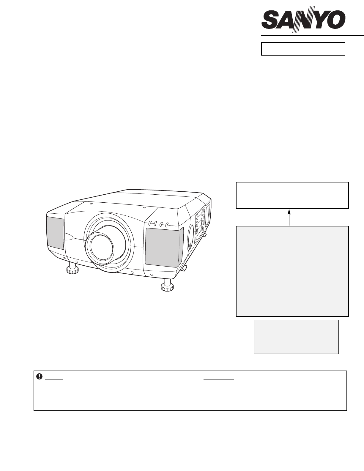
Multimedia Projector
Give complete “CHASSIS NO." for
parts order or servicing, it is shown on
the rating sheet on the cabinet of the
Projector.
Chassis No. MA4-HD2000N00
PA4-HD2000E00
NOTE: Match the Chassis No. on the rat-
ing sheet on the cabinet with the
Chassis No. in the Service
Manual.
If the Original Version Service
Manual Chassis No. does not
match the unites, additional
Service Literature is required.
You must refer to “Notices” to the
Original Service Manual prior to
servicing the unit.
MODEL NO. PLV-HD2000N
U.S.A., Canada
PLV-HD2000E
U.K., Europe
(Projection lens is optional.)
Original Version
RoHS
• This product does not contain any hazardous substances prohibited by the RoHS Directive. (You will
find “RSF” mark near the rating plate on the RoHS
compliant product.)
!
WARNING
• You are requested to use RoHS compliant parts for
maintenance or repair.
• You are requested to use lead-free solder.

■ Contents
- 2 -
■ Contents .................................................................................................................2
■ Safety Instructions..................................................................................................3
■ Technical Specifications.........................................................................................4
■ Circuit Protections ..................................................................................................5
■ Lamp Replacement ................................................................................................9
■ Maintenance and Cleaning ..................................................................................13
■ Mechanical disassemblies ...................................................................................15
■ Optical Unit disassemblies ...................................................................................40
● Optical Parts Location and Direction ..........................................................51
■ Troubleshooting....................................................................................................53
● No Picture ...................................................................................................53
● No Power ....................................................................................................58
● No Audio Output .........................................................................................62
● Temperature Abnormality ...........................................................................63
● Power Lens System Abnormality................................................................64
● Lamp Abnormality .......................................................................................65
■ Adjustments After Parts Replacement (Optical parts) .........................................66
■ Optical adjustments..............................................................................................67
■ Electrical Adjustments..........................................................................................78
● Adjustments after Parts Replacement (Electrical Parts).............................78
● Service Adjustment Menu Operation ..........................................................79
● Service Mode Adjustment Menu.................................................................80
● Circuit Adjustments .....................................................................................82
● Service Adjustment Data table (Factory Set Data List) ..............................88
● Special Menu ..............................................................................................97
■ Control Port Functions .........................................................................................98
■ Waveforms .........................................................................................................106
■ IC Block Diagrams .............................................................................................107
■ Mechanical and Optical Parts list.......................................................................113
■ Electrical Parts list..............................................................................................124
■ Diagrams and Drawings ......................................................................................A1
● Parts description and reading in schematic diagram .................................A2
● Block Diagrams ..........................................................................................A3
● Schematic Diagrams ..................................................................................A4
● Printed Wiring Board Diagrams................................................................A17
● Pins description of ICs, transistors, diodes ..............................................A29
WARNING:
The chassis of this projector is isolated (COLD) from AC line by using the converter transformer. Primary side of
the converter and lamp power supply unit circuit is connected to the AC line and it is hot, which hot circuit is identified with the line ( ) in the schematic diagram. For continued product safety and protection of personnel
injury, servicing should be made with qualified personnel.
The following precautions must be observed.
SAFETY PRECAUTIONS
1: An isolation transformer should be connected in the
power line between the projector and the AC line
before any service is performed on the projector.
2: Comply with all caution and safety-related notes pro-
vided on the cabinet back, cabinet bottom, inside the
cabinet or on the chassis.
3: When replacing a chassis in the cabinet, always be
certain that all the protective devices are installed
properly, such as, control knobs, adjustment covers
or shields, barriers, etc.
DO NOT OPERATE THIS PROJECTOR WITHOUT
THE PROTECTIVE SHIELD IN POSITION AND
PROPERLY SECURED.
4: Before replacing the cabinet cover, thoroughly
inspect the inside of the cabinet to see that no stray
parts or tools have been left inside.
Before returning any projector to the customer, the
service personnel must be sure it is completely safe to
operate without danger of electric shock.
SERVICE PERSONNEL WARNING
Eye damage may result from directly viewing the light produced by the Lamp used in this equipment. Always turn
off Lamp before opening cover. The Ultraviolet radiation eye protection required during this servicing.
Never turn the power on without the lamp to avoid electric-shock or damage of the devices since the stabilizer
generates high voltages(15kV - 20kV) at its starts.
Since the lamp is very high temperature during units operation replacement of the lamp should be done at least
45 minutes after the power has been turned off, to allow the lamp cool-off.
PRODUCT SAFETY NOTICE
Product safety should be considered when a component replacement is made in any area of the projector.
Components indicated by mark in the parts list and the schematic diagram designate components in which
safety can be of special significance. It is, therefore, particularly recommended that the replacement of there parts
must be made by exactly the same parts.
■ Safety Instructions
- 3 -
CAUTION
RISK OF EXPLOSION IF BATTERY IS REPLACED BY AN INCORRECT TYPE.
DISPOSE OF USED BATTERIES ACCORDING TO THE INSTRUCTIONS.
CAUTION
Not for use in a computer room as defined in the Standard for the Protection of Electronic Computer/Data
Processing Equipment, ANSI/NFPA 75.
Ne puet être utillisé dans une salle d’ordinateurs telle que définie dans la norme ANSI/NFPA 75 Standard for
Protection of Electronic Computer/Data Processing Equipment
Owner’s Manual
AC Power Cord
Wireless/Wired Remote Control Transmitter and Batteries
6 Types Light-Block Sheet (For option lens)
2 Types Lens Attachment (For option lens)
Real Color Manager Pro
1.64" TFT Active Matrix type, 3 panels
Multi-media Projector
82.0 lbs (37.2 kg)
22.9" x 10" x 30.9" (581 mm x 252 mm x 783 mm)
2048 x 1080 dots
6,635,520 (2048 x 1080 x 3 panels)
PAL, SECAM, NTSC, NTSC4.43, PAL-M and PAL-N (With option video board)
Up, Down, Left and Right
Projector Type
Net Weight
Dimensions
(W x H x D)
Panel Resolution
Number of Pixels
Color System
Scanning Frequency
LCD Panel System
300 watt type x 4
Projection Lamp
480i, 480p, 575i, 575p, 720p, 1035i, 1080i-50 and 1080i-60
Component Signal
H-sync. 15 ~ 120 KHz, V-sync. 24 ~ 120 Hz
Motorized Lens Shift
BNC Type x 4 (Dual-link SDI Input /Output A and B ) Y/Cb/Cr, RGB format compatible
Input 1 Jacks
BNC Type x 5 (R/Pr, G/Y, B/Pb, H/HV and V), RCA Type (Audio R and L)
and DIN 8-pin (Control port)
Input 2 Jacks
DVI-I Terminal (Digital/Analog), RCA Type (Audio R and L)
and DIN 8-pin (Control port)
Input 3 Jacks
Accessories
41 ˚F ~ 86 ˚F (5 ˚C ~ 30 ˚C)
14 ˚F ~ 140 ˚F (-10 ˚C ~ 60 ˚C)
Operating Temperature
Storage Temperature
0˚ to 5.7˚
Feet Adjustment
AC 120 V (16 A Max. Ampere), 50 / 60 Hz
(The U.S.A and Canada)
AC 200 ~ 240 V (9.0 A Max. Ampere), 50 / 60 Hz
(Continental Europe and The U.K.)
Voltage and
Power Consumption
Serial port in (DB 9), Serial port out (DB 9), USB port and
Audio out (RCA Type R and L)
Other Jacks
Power Source : AA or R06 Type x 2
Operating Range : 16.4’ (5m) / ±30˚
Dimensions : 2.0” x 1.1” x 7.1” (50mm x 29mm x 181mm)
Net Weight : 0.34 lbs (154 g) (including batteries)
Remote Control Transmitter
● Specifications are subject to change without notice.
● LCD panels are manufactured to the highest possible standards. At least 99.99% of the pixels are effective,
however a tiny fraction of the pixels (0.01% or less) may be ineffective by the characteristics of the LCD
panels.
● Each projector has its own characteristics.
When projecting with several projectors on the same screen or side by side, you may recognize different
white balance and color uniformity on each projector.
This symbol on the nameplate means the product is Listed by Underwriters Laboratories
Inc. It is designed and manufactured to meet rigid U.L. safety standards against risk of
fire, casualty and electrical hazards.
The CE Mark is a Directive conformity mark of the European Community (EC).
- 4 -
■ Technical Specifications
This projector provides the following circuit protections to operate in safety. If the abnormality occurs inside the projector, it will automatically turn off by operating one of the following protection circuits.
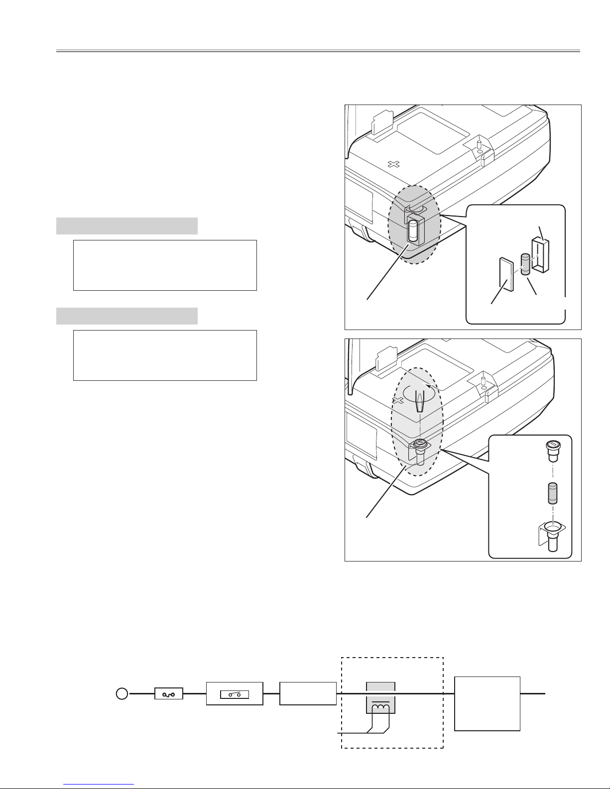
A fuse(F901) is located inside of the projector. When the
POWER indicator is not lighting, the fuse may be
opened. Check the fuse as following steps.
The fuse should be used with the following type;
● Fuse
How to replace the fuse
1. Remove the cabinet top following to "Mechanical
Disassemblies".
2. Remove the cover and the fuse from fuse holder.
To install the fuse, take reversed step in the above.
Fuse Part No.: 323 028 4202
TYPE 15.0A400V FUSE
SOC CORP. SHV14 15A N4
Fuse Part No.: 323 033 1807
TYPE 30.0A250V FUSE
SOC CORP. KST2 30A
PLV-HD2000E
PLV-HD2000N
Fuse (F901)
Fuse (F901)
Cover
Cover
Fuse
Fuse
Holder
Holder
● AC Current Sensor
AC current sensor is used only for PLV-HD2000E.
The AC Current Sensor is provided to prevent damage to the power supply circuits.
When AC input voltage is under 108V at MAINS SW ON, the AC Current Sensor will be operated and the CPU
does not turn the projector on, and both of READY and WARNING TEMP. indicators start flashing.
Check that the AC current sensor signal is correct. L : Abnormality
K96W
- 5 -
■ Circuit Protections
Hot circuit
AC-INPUT
FUSE
F901
MAINS SW
SW901
NOISE FILTER
LF901
CURRENT SENSOR
A903
ASS'Y POWER
Circuit Protections
Lamp Cover switch
SW902
When the lamp cover is removed or no close completely, the lamp cover switch (SW902) cuts off
12V_PFC line to the PFC unit, and then a projector will
be shut down.
After opening the lamp cover for replacing the lamp
unit, place the lamp cover correctly, otherwise the projector can not be turned on.
Lamp Cover
● Lamp cover switch
● Power Failure Protection
Power failure protection diodes detect abnormal voltage on the power supply circuits or the fan operation stop.
When both of the WARNING TEMP. and READY Indicators are flashing:
When the projector detects an internal problem, it will shut down
automatically and both of the WARNING TEMP. and READY Indicators starts
flashing. In this condition, the projector cannot be turned on even if you press
the POWER ON-OFF button on the remote control unit or on the side control.
If this case happened, disconnect and reconnect the AC power cord, and
then turn on the projector again to check its operation. If the projector shuts
down again or fails to be turned on, the internal check and repair will be
required.
Check items listed below;
● Power Failure Protection
● AC Current Sensor (See the previous page.)
● Temperature Check of Lamps
● Lamp Cover Switch
READY
LAMP
LAMP
REPLACE
WARNING
TEMP.
FRONT INDICATORS
WARNING TEMP.
Indicator
READY
Indicator
WARN ING
TEMP.
READY
LAMP
REPLACE
LAMP
REAR INDICATORS
Temperature switches (SW 903~906)
are arranged near the four lamps.
Temperature switches will operate, if
temperature reaches 110 degrees.
Temperature switches
--- open at 110 degrees.
SW903 ---Lamp1
SW904 ---Lamp2
SW905 ---Lamp3
SW906 ---Lamp4
When temperature switches become
open, they cut off 12V_PFC line to
PFC(power factor control) unit, and
then a projector will be shut down.
● Temperature Check of Lamps
Temperature switch
SW906 (For Lamp4)
Temperature switch
SW905 (For Lamp3)
Temperature switch
SW903 (For Lamp1)
Temperature switch
SW904 (For Lamp2)
- 6 -
READY
LAMP
LAMP
REPLACE
WARNING
TEMP.
When the WARNING TEMP. Indicator is flashing:
The WARNING TEMP. Indicator flashes red to let you know the internal
temperature of the projector exceeds the normal level. If the temperature goes
up further, the projector will be turned off automatically and the Ready indicator
will go out. (The WARNING TEMP. Indicator continues flashing.) After the
cooling-off period, the READY Indicator lights on again and the projector can be
turned on by pressing the POWER ON-OFF button on the remote control unit or
on the side control. When you turn on the projector, the WARNING TEMP.
Indicator will go out.
If the WARNING TEMP. Indicator is still flashing, check the followings;
● Installation
● Air Filter
● Temperature Monitor System
FRONT INDICATORS
WARNING TEMP.
Indicator
WARNING
TEMP.
READY
LAMP
REPLACE
LAMP
REAR INDICATORS
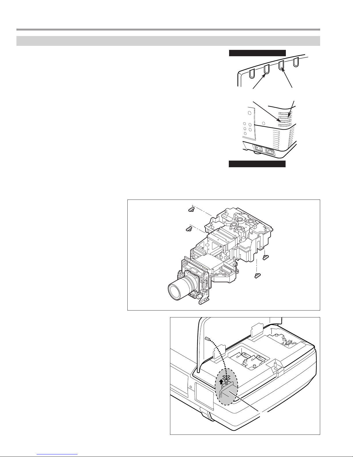
This projector is equipped with cooling fans for protection
from overheating. Pay attention to following to ensure proper ventilation and avoid a possible risk of fire and malfunction.
- Do not cover vent slots.
- Keep bottom clear any objects. Obstructions may block cooling air.
AIR INTAKE VENTS
EXHAUST VENTS
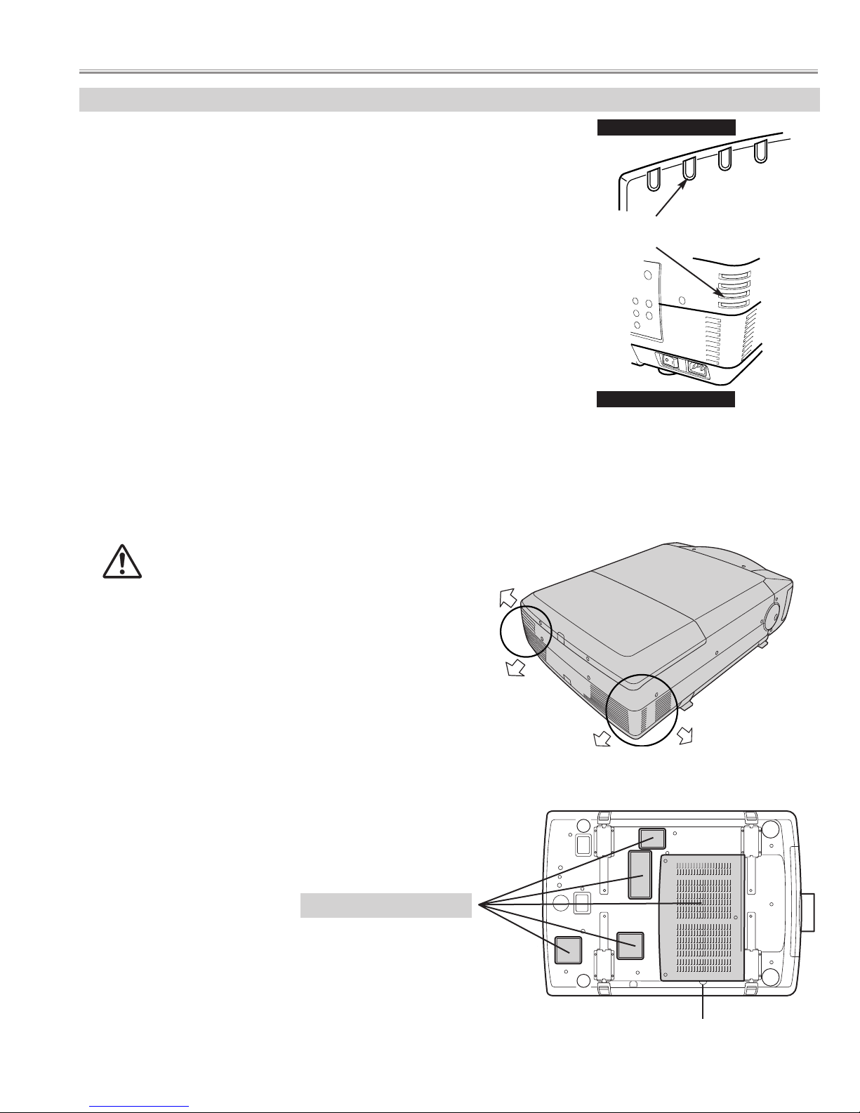
HOT AIR EXHAUSTED !
Air blown from exhaust vent is hot. When using
or installing a projector, following precautions
should be taken.
● Do not put flammable objects near these vents.
● Keep rear grills at least 3’ (1m) away from any object,
especially heat-sensitive object.
● Do not touch this area, especially screws and metallic
parts. This area will become hot while a projector is used.
HOT
● Installation
● Air Filter
- Air filter is clogged with dust particles. Remove dust from the air filter by following instruction in the "Air filter care
and cleaning".
- Ventilation slots of the projector are blocked. In such case, reposition the projector so that ventilation slots are not
obstructed.
- Check if projector is used at higher temperature place(Normal operate is 5 to 35°C or 41 to 95°F)
- 7 -
Circuit Protections
AIR FILTER

■ To control the driving power of the cooling fans.
This projector detects internal temperature and automatically controls operating power of cooling fans.
The CPU checks the temperature and atmospheric pressure inside a projector. It checks a temperature using
temperature sensor-IC5801and it checks an atmospheric pressure using pressure sensor-IC4849.
The CPU controls the driving power of the cooling fans so the temperature inside the projector is maintained to
normal temperature.
■ To shut down the projector.
The CPU checks temperature of Blue polarized glass (PTH901) and inhalation air(IC5801). If each part temperature reaches to abnormal temperature, the CPU will turn off a projector, and will blink WARNING TEMP. indicator at intervals of 0.5 seconds. Cooling fans operate until temperature returns to normal. WARNING TEMP.
indicator will stop blink, if temperature returns to normal.
● Temperature Monitor System
Main Board
A-side
Front side
B-side
Temp. Sensor
IC1519
Temp. Sensor
(Inhalation air)
IC5801
Pressure Sensor
IC4849
Temp. Sensor
(Blue polarized glass)
PTH901
Temperature sensors location
Blue polarizer unit
- 8 -
Circuit Protections
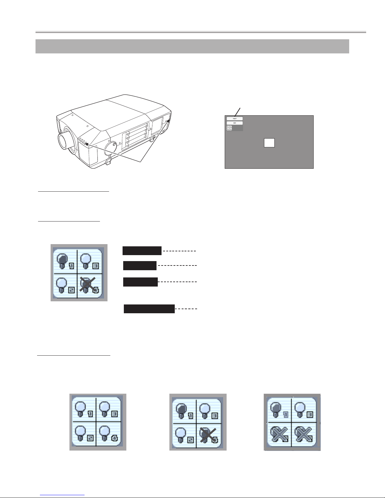
This Projector is equipped with 4 Projection Lamps to ensure brighter image and those lamps are controlled by Lamp
Management Function. Lamp Management Function detects status of all lamps and shows status on screen or on LAMP
REPLACE indicator. This function also automatically controls Lamp Mode when any of lamps is out for end of life or
malfunctions.
Projection Lamp lights normally.
Lamp Replace Indicator
This LAMP REPLACE indicator lights yellow when any of Projection Lamps is nearing its end, and flashes when any of them
becomes out. Check number of lamp on Lamp Status Display and replace lamp.
Yellow Lamp
Dim Lamp
X Mark on Lamp
Red Lamp
LAMP REPLACE
INDICATOR
Projection Lamp is turned off.
Projection Lamp is nearing its end. When image becomes
darker or color becomes unnatural, replace lamp. (LAMP
REPLACE indicator lights yellow.)
(LAMP REPLACE indicator flashes yellow.)
Projection lamp is defective or fails to be turned on. Restart
a projector on, and make sure lamp is on. If this mark still
appears, replace lamp corresponding with number marked
X.
LAMP STATUS
DISPLAY
Lamp Mode Changeover
Lamp Management Function automatically changes combination of lighting lamp (Lamp Mode) by detecting status of lamp.
When any of 4 lamps becomes out, Lamp Mode is changed over from 4 lamps to 2 lamps. And when any of 2 lamps are out,
a projector operates with 1 lamp. Lamp Mode can be switched to 4 lamps or 2 lamps manually.
4 LAMP MODE
2 LAMP MODE
(Example)
1 LAMP MODE
(Example)
Lamp Status Display
Lamp Status Display appears on screen when power switch is on or changed input position (input 1, input 2, Input 3 or input 4).
This shows status of each lamp as; ON, OFF, NEAR END, or OUT. Refer to following for each status.
20
INPUT AND LAMP STATUS
LAMP MANAGEMENT (before replacement)
- 9 -
■ Lamp Replacement
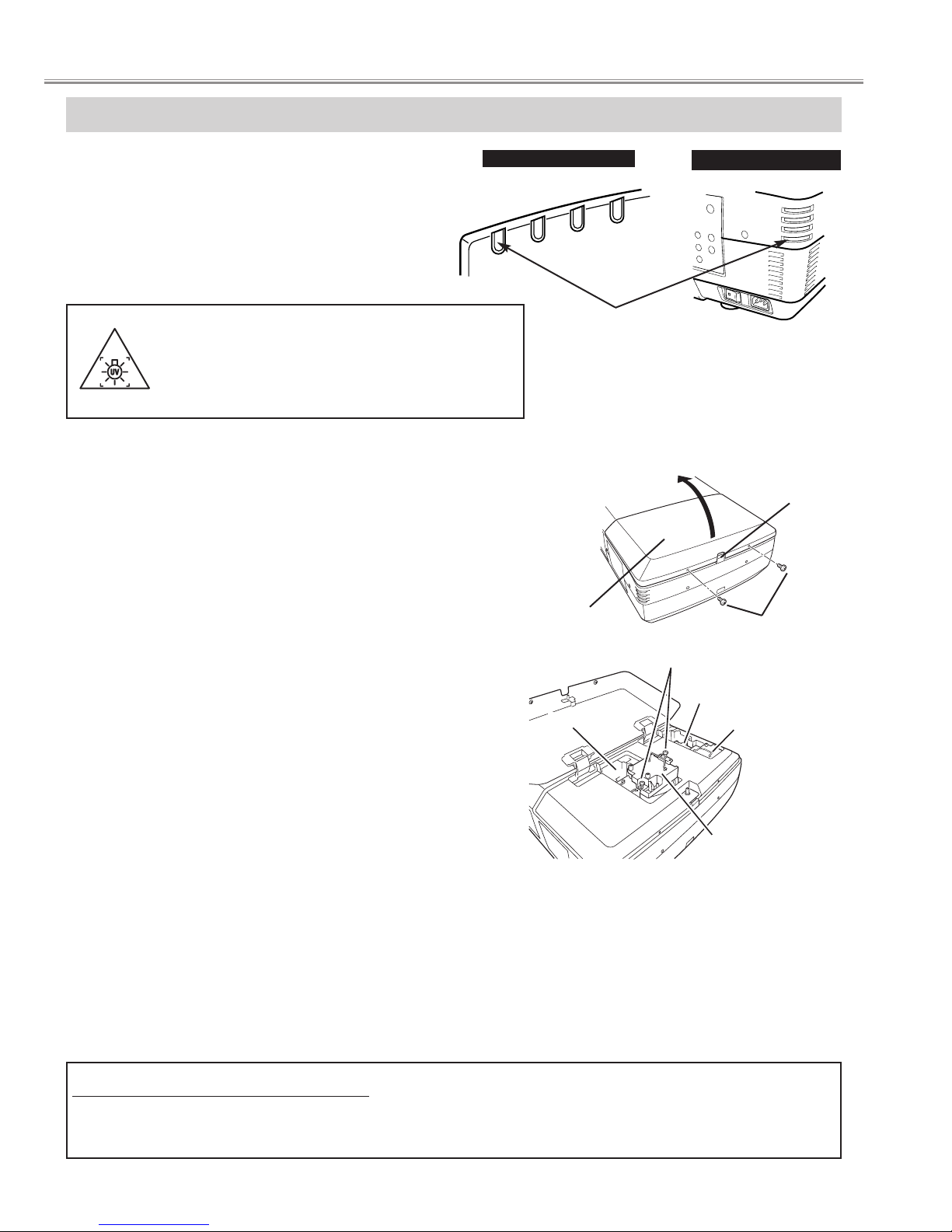
LAMP REPLACEMENT
Check number of lamp to be replaced on Lamp Status
Display.
Remove two screws on Lamp Cover and press button to
open Lamp Cover. (See right figure.)
1
3
Loosen two screws and pull out Lamp Assembly to be
replaced by grasping handle.
4
Turn off a projector and disconnect AC Power Cord.
Allow a projector to cool down for at least 45 minutes.
2
Replace Lamp Assembly with a new one and tighten two
screws. Make sure Lamp is set properly.
6
Follow these steps to replace lamp assembly.
Replace Lamp Cover and tighten two screws.
5
7
8
Connect AC Power Cord to a projector and turn a
projector on.
Reset Lamp Replacement Counter. (Refer to section
"Lamp Replace Counter".)
NOTE : Do not reset LAMP REPLACEMENT COUNTER when
lamp is not replaced.
BUTTON
SCREWS
SCREWS
LAMP1
LAMP2
LAMP
COVER
Make sure which number of lamp needs to
be replaced on Lamp Status Display.
Figure shows case of replacing LAMP 2.
CAUTION : Do not operate a Projector while any of lamps removed.
It may result in malfunctions, fire hazard, or other accidents.
NOTES ON LAMP REPLACEMENT
To maintain quality of picture (better balance of color and brightness in entire screen), we recommend replacing all 4 lamps at a time.
CAUTION : High pressure lamp may explode if improperly handled.
Refer to lamp replacement instructions.
When the life of the projection lamp of this projector
draws to an end, the LAMP REPLACE indicator
lights yellow. If this indicator lights yellow, replace
the lamp with a new one promptly.
The time when the LAMP REPLACE indicator lights
is depending on the lamp mode.
LAMP3
LAMP4
WARNING :
TURN OFF THE UV LAMP BEFORE OPENING
THE LAMP COVER. USE UV RADIATION EYE
AND SKIN PROTECTION DURING SERVICING.
REAR INDICATORS
READY
LAMP
LAMP
REPLACE
WARNING
TEMP.
WARNING
TEMP.
READY
LAMP
REPLACE
LAMP
FRONT INDICATORS
LAMP REPLACE
INDICATOR
- 10 -
Lamp replacement
CAUTION
Do not drop a lamp assembly or touch a glass
bulb! Glass can shatter and may cause injury.
CAUTION
For continued safety, replace with a lamp
assembly of same type.
Allow a projector to cool for at least 45 minutes
before you open Lamp Cover. Inside of a
projector can become very hot.
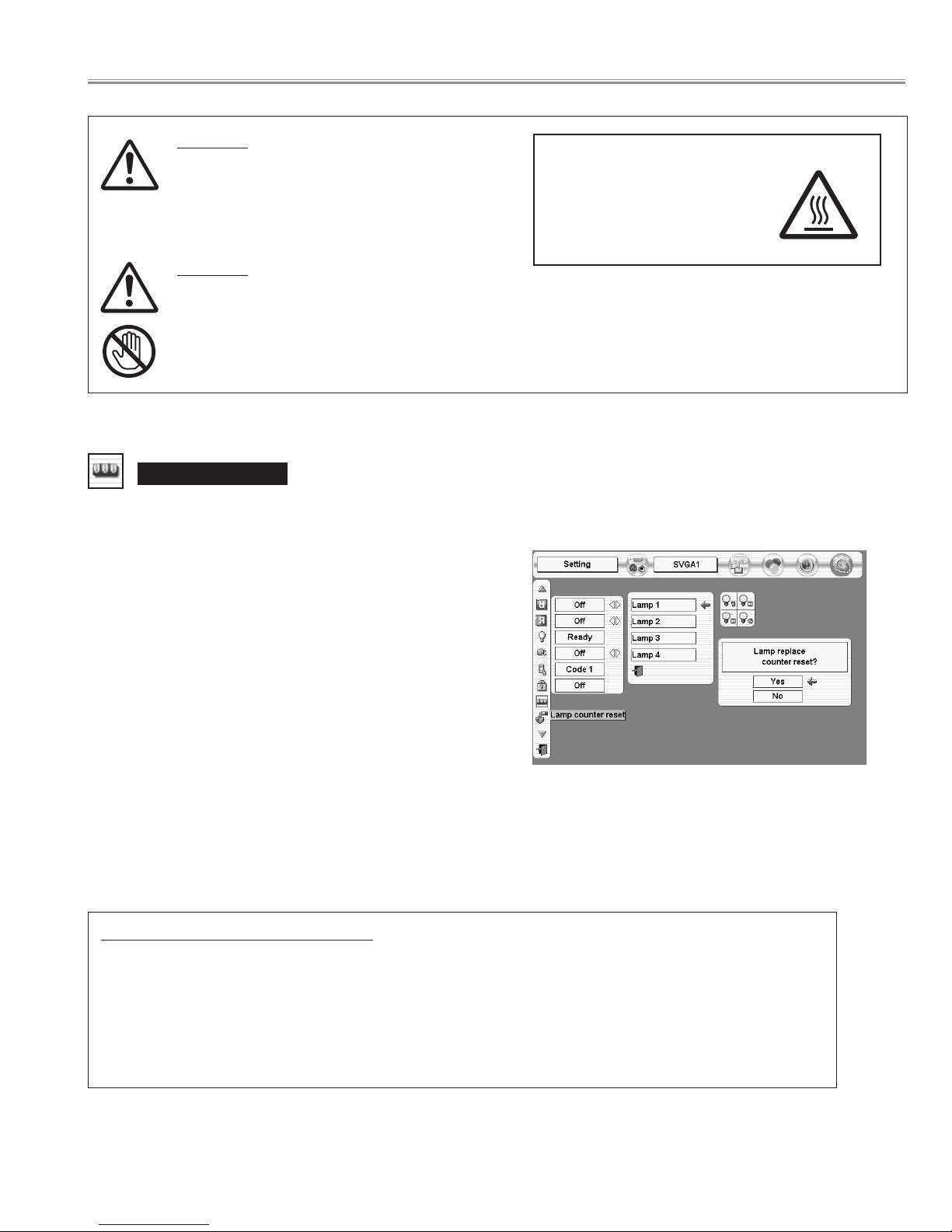
Lamp counter reset
Be sure to reset Lamp Counter when Lamp Assembly is replaced. When Lamp Replace Counter is reset, LAMP
REPLACE indicator stops lighting.
Turn projector on, press MENU button and ON-SCREEN
MENU will appear. Press POINT LEFT/RIGHT button(s) to
move a red frame pointer to SETTING Menu icon.
1
Press POINT DOWN button to move a red frame pointer to
“Lamp counter reset” and then press
SELECT button.
2
Do not reset Lamp Replace Counter except after Projection lamp is
replaced.
Another confirmation dialog box appears and select [Yes] to
reset Lamp Replace Counter.
4
Move arrow to replaced lamp number (Lamp 1, Lamp 2, Lamp 3
or Lamp 4) and then press
SELECT button. Message "Lamp
replace counter Reset?" is displayed. Move pointer to [Yes] and
then press SELECT button.
3
NOTE: Be sure to reset correct lamp number otherwise LAMP
REPLACE indicator continues lighting.
ORDER REPLACEMENT LAMP
Replacement Lamp can be ordered through your dealer. When ordering a Projection Lamp, give the
following information to the dealer.
●
Model No. of your projector : PLV-HD2000N / PLV-HD2000E
● Replacement Lamp Type No. : POA-LMP100
(Service Parts No. 610 327 4928)
- 11 -
Lamp replacement
CAUTION
HIGH VOLTAGE
HOT
This projector uses a high-pressure lamp which must be handled carefully and properly. Improper handling
may result in accidents, injury, or create a fire hazard.
● Lamp lifetime may differ from lamp to lamp and according to the environment of use. There is no
guarantee of the same lifetime for each lamp. Some lamps may fail or terminate their lifetime in a shorter
period of time than other similar lamps.
● If the projector indicates that the lamp should be replaced, i.e., if the LAMP REPLACE INDICATOR lights
up, replace the lamp with a new one IMMEDIATELY after the projector has cooled down.
( Follow carefully the instructions in the LAMP REPLACEMENT section of owner's manual. ) Continuous
use of the lamp with the LAMP REPLACE INDICATOR lighted may increase the risk of lamp explosion.
● A Lamp may explode as a result of vibration, shock or degradation as a result of hours of use as its
lifetime draws to an end. Risk of explosion may differ according to the environment or conditions in which
the projector and lamp are being used.
IF A LAMP EXPLODES, THE FOLLOWING SAFETY PRECAUTIONS SHOULD BE TAKEN.
If a lamp explodes, disconnect the projector’s AC plug from the AC outlet immediately. Contact an
authorized service station for a checkup of the unit and replacement of the lamp. Additionally, check
carefully to ensure that there are no broken shards or pieces of glass around the projector or coming out
from the cooling air circulation holes. Any broken shards found should be cleaned up carefully. No one
should check the inside of the projector except those who are authorized trained technicians and who are
familiar with projector service. Inappropriate attempts to service the unit by anyone, especially those who
are not appropriately trained to do so, may result in an accident or injury caused by pieces of broken glass.
LAMP HANDLING PRECAUTIONS
- 12 -
Lamp replacement
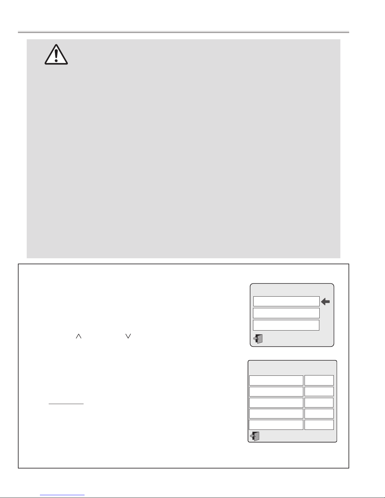
You can check the lamp used time and projector used time following to below
procedure.
1 Enter special menu mode.
Press and hold POWER ON-OFF button on the side control of the projector
or the remote control unit for more than 20 seconds.
Press point Up( ) and DOWN ( )buttons to select "Counter" and than
press "SELECT" button.
2 The projector used time and lamp used time will be displayed on the screen.
3 Press Power button "ON-OFF" once and close the special menu mode.
The LAMP REPLACE indicator will light yellow when the total lamp used time
reaches 2,000 hours - (✽). This is to indicate that lamp replacement is
required.
(✽) The specification is subject to change without notice.
● How to check Lamp Used Time
Special
Counter
Fan control
RS232C
Counter
Projector
Lamp 1
Lamp 2
Lamp 3
Lamp 4
123H
123H
123H
123H
123H
After long periods of use, dust and other particles will accumulate on the LCD panel, prism, mirror, polarized glass,
lens, etc., causing the picture to darken or color to blur. If this occurs, clean the inside of optical unit.
Remove dust and other particles using air spray. If dirt cannot be removed by air spray, disassemble and clean the
optical unit.
● Cleaning with air spray
1. Remove the cabinet top following to "Mechanical Disassemblies".
2. Clean up the LCD panel and polarized glass by using the air spray from the cabinet top opening.
Caution:
Use a commercial (inert gas) air spray designed for cleaning camera and computer equipment. Use a resin-based nozzle only. Be vary careful not to damage optical parts with the nozzle tip. Never use any kind of cleanser on the unit. Also,
never use abrasive materials on the unit as this may cause irreparable damage.
● Disassembly Cleaning
Disassembly cleaning method should only be performed when the unit is considerable dirty and cannot be sufficiently cleaned by air spraying alone.
Be sure to readjust the optical system after performing disassembly cleaning.
1. Remove the cabinet top and main units following to "Mechanical Disassemblies".
2. Remove the optical base top following to"Optical Unit Disassemblies". If the LCD panel needs cleaning, remove the
LCD panel unit following to "LCD panel/Prism ass'y replacement".
3. Clean the optical parts with a soft cloth. Clean extremely dirty areas using a cloth moistened with alcohol.
Caution:
The surface of the optical components consists of multiple dielectric layers with varying degrees of refraction.
Never use organic solvents (thinner, etc.) or any kind of cleanser on these components.
Since the LCD panel is equipped with an electronic circuit, never use any liquids (water, etc.) to clean the unit. Use of
liquid may cause the unit to malfunction.
Unplug the AC power cord before cleaning.
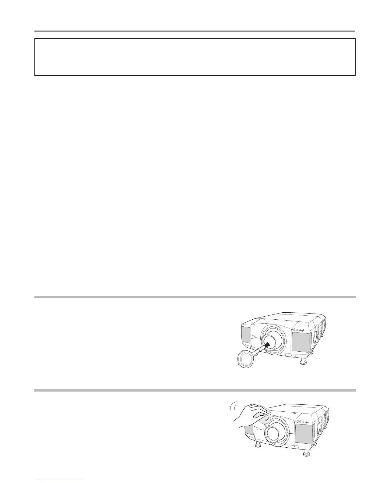
Gently wipe the projection lens with a cleaning cloth that contains
a small amount of non-abrasive camera lens cleaner, or use a
lens cleaning paper or a commercially available air blower to clean
the lens. Avoid using an excessive amount of cleaner. Abrasive
cleaners, solvents, or other harsh chemicals might scratch the
surface of the lens.
Cleaning the Projection Lens
Cleaning the Projector Cabinet
Unplug the AC power cord before cleaning.
Gently wipe the projector body with a dry soft cloth. When the
cabinet is heavily soiled, apply a small amount of mild detergent
and finish with a dry soft cloth. Avoid using an excessive amount
of cleaner. Abrasive cleaners, solvents, or other harsh chemicals
might scratch the surface of the cabinet.
- 13 -
■ Maintenance and Cleaning
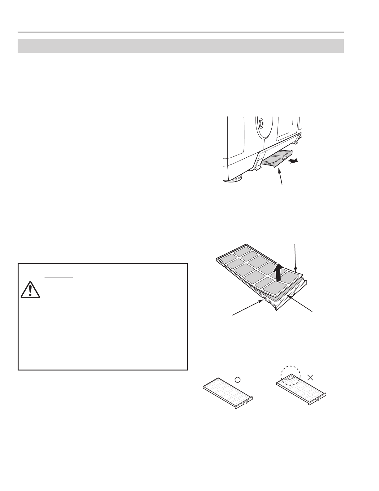
AIR FILTER CARE AND CLEANING
Air Filter prevents dust from accumulating on surface of Projection Lens and Projection Mirror. Should Air Filter
become clogged with dust particles, it will reduce Cooling Fans' effectiveness and may result in internal heat build up
and adversely affect life of a projector.
Clean Air Filter following steps below:
1
Turn power off, and disconnect AC power cord from AC
outlet.
2
Pull out air filter unit from the projector.
3
Pulling up center frame of air filter top, separate air filter
top and sheet from air filter base.
4
Clean each parts with brush, vacuum cleaner dust and
particles.
5
Assemble sheet, air filter top and air filter base, and
replace air filter unit to a projector.
CAUTION
- Do not operate a projector with air filter removed.
Or dust may accumulate on LCD panel and
Mirror degrading picture quality.
- Do not put small parts into air Intake Vents. Or It
may result in malfunction of a projector.
- The filter be careful and handle. The effect of the
filter runs out in case of a leak and it being
broken off.
AIR FILTER UNIT
AIR FILTER TOP
AIR FILTER BASE
SHEET
Caution; Assembles sheet and filter base
- 14 -
Maintenance and Cleaning
NOTE: If the dust cannot be removed by cleaning, it is
probably time to replace the air filters with new
ones.
Air Filter Parts No. 610 301 4814
Before Disassemblies :
Turn off a projector and disconnect the AC power cord.
When remove the lens shift unit, shift to the position from which the attachment screws of a lens shift unit and an
optical base unit can be removed.
Disassemble should be made following procedures in numerical order.
Following steps show the basic procedures, therefore unnecessary step may be
ignored.
Caution:
The parts and screws should be placed exactly the same position as the original oth-
erwise it may cause lose of performance and product safety.
The wiring method of the leads and ferrite cores should be returned exactly the same
state as the original otherwise it may cause lose of performance and product safety.
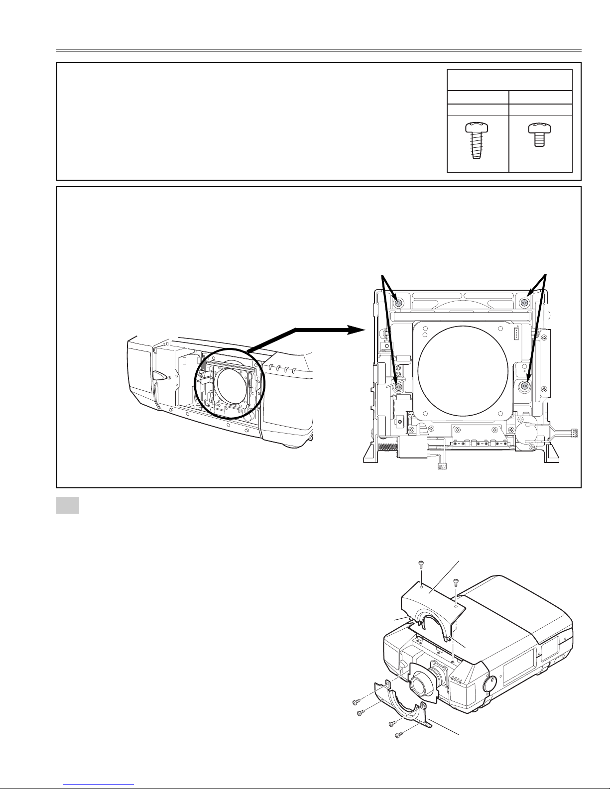
Screw
Screw
Lens shift unit is moved to the position
from which an attachment screws can
be removed, as shown in a figure.
Lens shift unit
- 15 -
Fig.1-1
1-1
Cabinet-front-top unit and Cabinet-front-bottom unit removal.
Note :Be careful not to damage Hook. The cabinet-front-top unit is being fixed with cabinet-front-bottom by hook.
1. Remove 2 screws-A.
Push part(a) and pull the Cabinet-front-top unit upward.
2. Remove 4 screws-B and remove the Cabinet-front-bottom unit.
(See Fig.1-1)
Refer to Lens replacement and installation manual.
■ Mechanical disassemblies
Screws Expression
(Type
Diameter x Length) mm
T type M Type
Ta pping screw Machine screw
A
Hook
(a)
B
B
B
B
Cabinet front top
unit
A
(a)
Cabinet front bottom unit
- 16 -
Fig.1-3
Fig.1-4
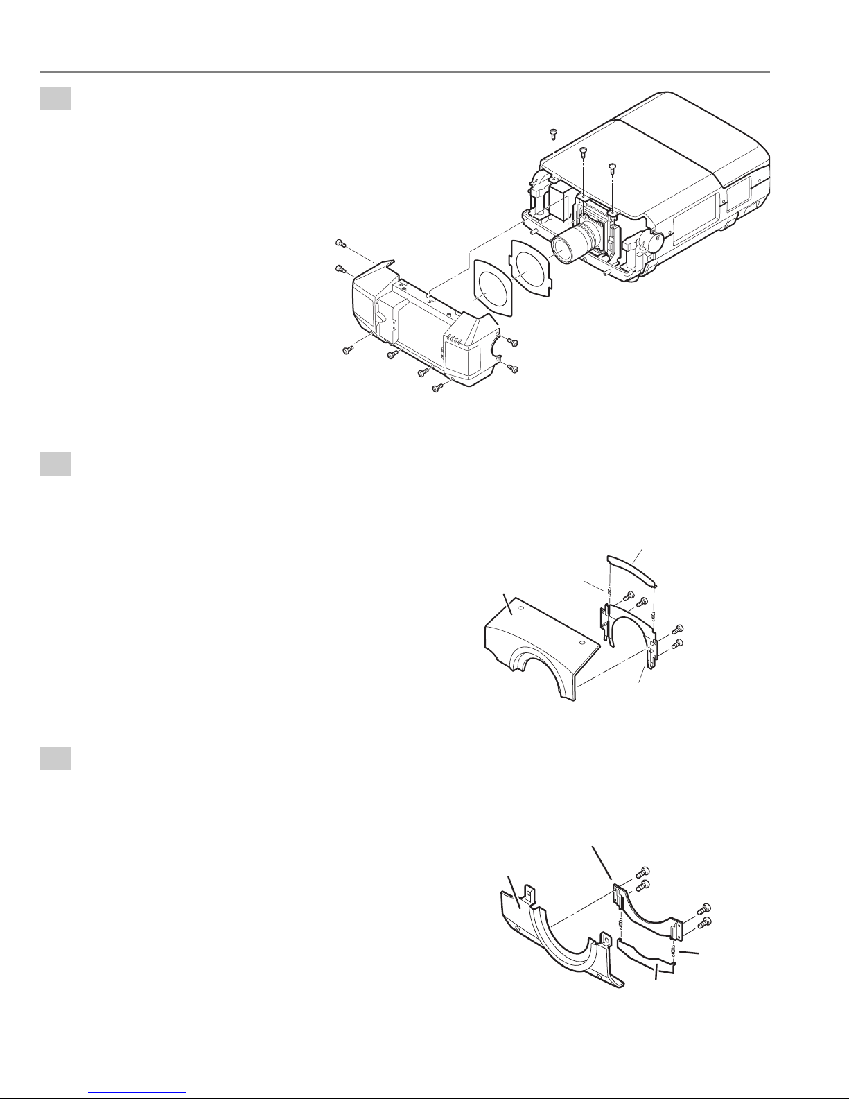
1-3
Cabinet front-top-unit disassemblies.
1. Remove 4 screws and remove the Mounting cover lens-A.
2. Remove 2 Spring coils and remove Cover lens-A.
(See Fig.1-3)
1-4
Cabinet front-bottom-unit disassemblies.
1. Remove 4 screws and remove the Mounting Cover lens-B.
2. Remove 2 Spring coils and remove Cover lens-A.
(See Fig.1-4)
Mechanical disassemblies
Fig.1-2
1-2
Cabinet-front unit removal.
1. Remove 11 screws and remove the Cabinet-front unit.
(See Fig.1-2)
A
A
A
A
A
Cabinet front unit
A
A
A
A
A
A
Cover lens-A
Spring coil-A
Cabinet front top
Mounting cover lens-A
Mounting cover lens-B
Cabinet front bottom
Spring
coil-B
Cover lens-A
- 17 -
Mechanical disassemblies
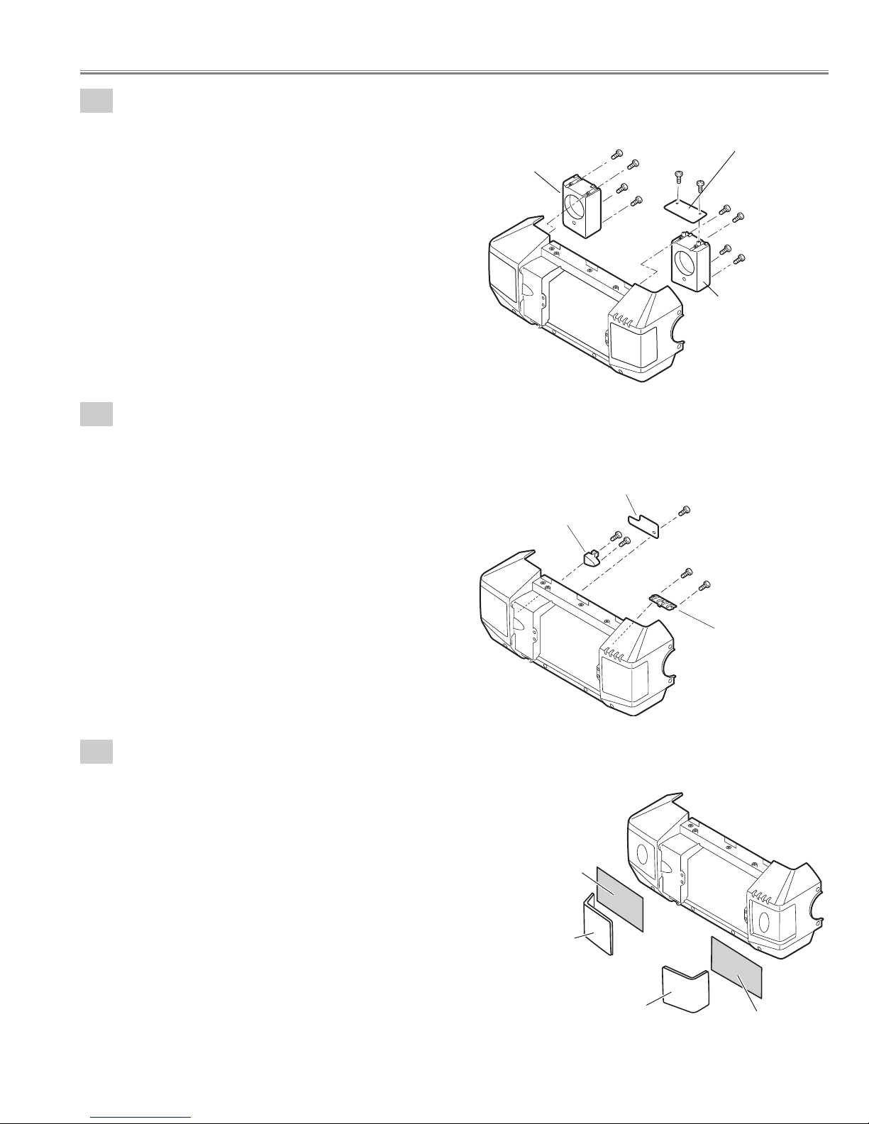
1-5
Speaker boxes and Front LED Board removal.
1. Remove 4 screws-A and remove the Speaker box-A.
2. Remove 4 screws-B and remove the Speaker box-B.
3. Remove 2 screws-C and remove the Front LED Board.
(See Fig.1-5)
Fig.1-5
1
-6
Decoration Inlays and R/C-1 Board removal.
1. Remove screw-A and remove the R/C-1 Board.
2. Remove 2 screws-B and remove the DEC Inlay R/C-F.
3. Remove 2 screws-C and remove the DEC Inlay-A.
(See Fig.1-6)
Fig.1-6
1
-7
Speaker Grills and Nets removal.
1. The bent portion is stretched and remove the Grille SP-L,
remove the Grille SP-R from cabinet front.
2. Remove the Nets.
(See Fig.1-7)
Mark the Grills as they are removed from the Cabinet front so that
they may be reassembled in the same location from which they
were removed. Be careful of the attached direction of Grills.
Fig.1-7
Speaker unit-A
A
A
C
A
A
Front LED Board
C
B
B
Speaker unit-B
B
B
Cabinet front
DEC Inlay R/C-F
Net
R/C 1 Board
B
B
A
C
C
DEC Inlay A
Cabinet front
Grill SP-L
Grill SP-R
Net
- 18 -
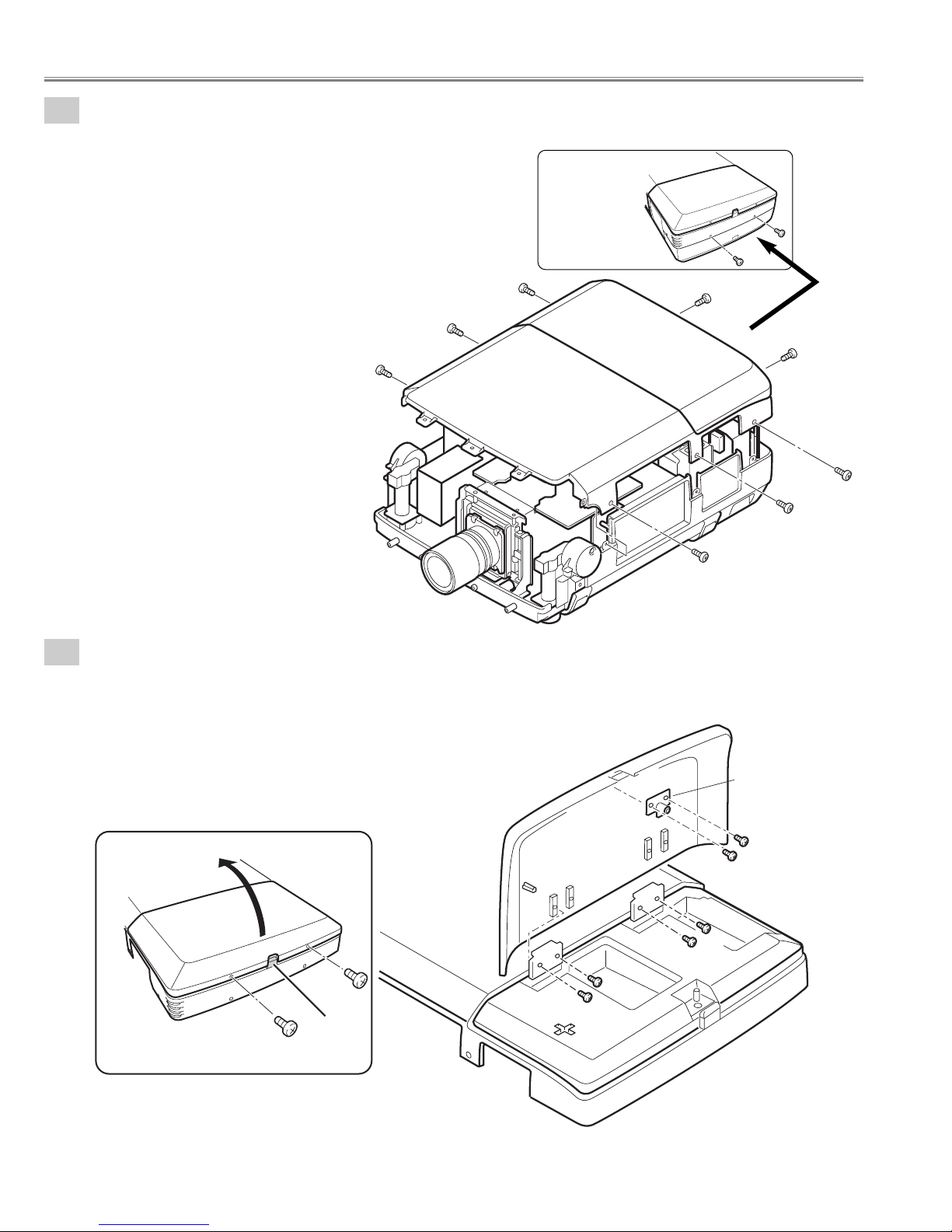
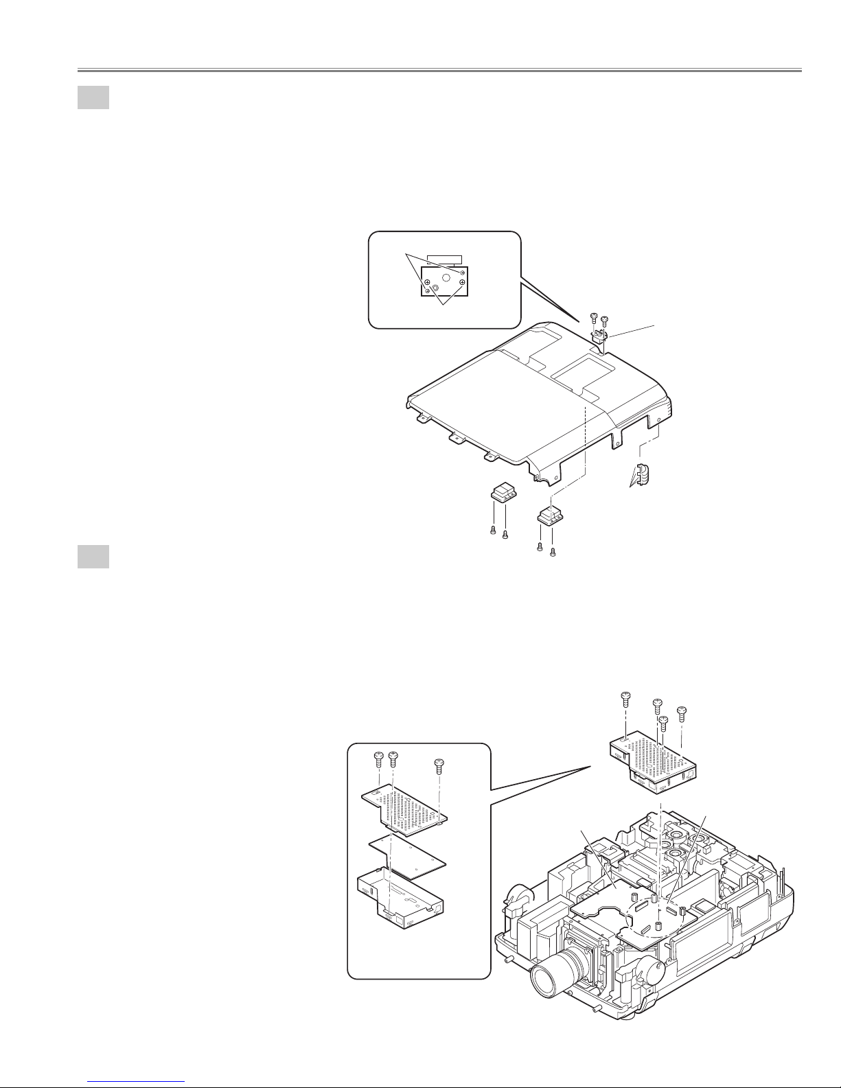
2-1
Cabinet-top unit removal.
1. Remove 8 screws and remove the Cabinet-top unit.
(See Fig.2-1)
2-2
Lamp cover and Push Latch-B removal.
1. Remove 2 screws-A and press button to open the Lamp cover.
2. Remove 4 screws-B and remove the Lamp cover.
3. Remove 2 screws-C and remove the Push Latch-B.
(See Fig.2-2, 2-2a)
Fig.2-1
Fig.2-1a
Fig.2-2
Fig.2-2a
Back View
Mechanical disassemblies
Cabinet top unit
Lamp cover
A
Press
Button
Push Latch-B
C
Lamp cover
Cabinet top
B
A
B
C
B
B
- 19 -
2-3
Decoration Inlay-B, Push Latch-A, and Hinges removal.
1. Remove 4 screws-A and remove the 2 Hinges.
2. Remove 2 screws-B and remove the push Latch-A.
3. Remove DEC Inlay-B. (Unhook the Cabinet top and take the DEC Inlay off inside.)
Push part(a) and pull the DEC Inlay inside.
(See Fig.2-3, 2-3a)
3
-1
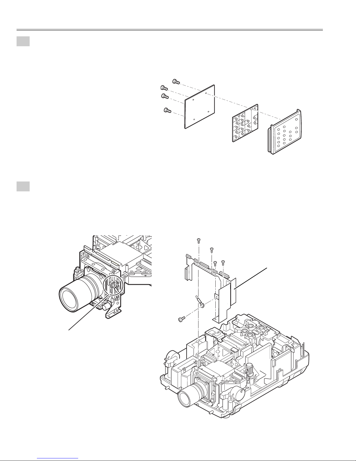
BGA Board removal.
Fig.2-3
Fig.2-3a
Fig.3-1
Fig.3-1a
Mechanical disassemblies
1. Remove 4 screws-A and remove the BGA unit.
Be careful not to damage connector, Main Board and BGA Board are connected.
2. Remove 3 screws-B and disassemble the BGA unit.
(See Fig.3-1,3-1a)
Do not remove
Remove the screws
Cabinet top
B
B
Push Latch-A
Hook
Hinge
Hinge
A
A
A
A
B
B
B
Main Board
Shield BGA-B
(a)
A
DEC Inlay-B
A
A
A
BGA unit
Be careful connectors
BGA Board
Shield BGA-A
- 20 -
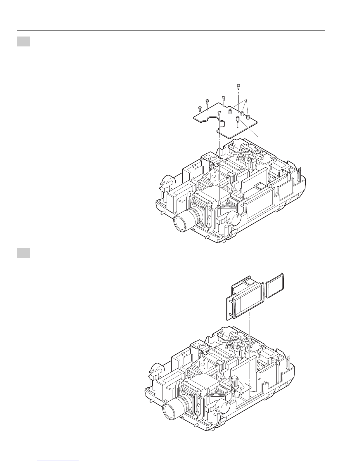
3-2
Main Board removal.
Remove the connectors and the flexible cables of the LCD panels from the Main Board.
(Never touch the electrode of flexible cables.)
1. Remove 5 screws-A.
2. Remove spacer-A and remove the Main Board.
(Do not remove the Spacer-B.)
(See Fig.3-2)
4-1
Control switch unit and Terminal slots unit removal.
1. Remove the Control switch unit upward.
2. Remove the Terminal slots unit upward.
(See Fig.4-1)
Fig.3-2
Fig.4-1
Mechanical disassemblies
A
MAIN Borad
A
A
A
A
Spacer-B
(Do not remove)
Spacer-A
Control-Switch
Unit
Terminal slots
Unit
- 21 -
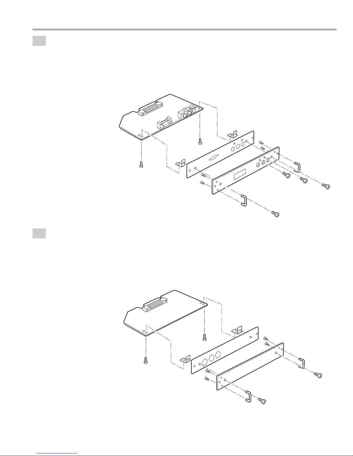
4-2
Terminal Board units and RS232C Board removal.
Fig.4-2
Fig.4-3
1. Remove 8 screws-A and remove the Terminal Board units 1-4.
2. Remove screw-B.
3. Remove 4 screws-C and remove the RS232C Board.
4. Remove screw-D and remove Grounding Lead from the RS232C Board.
(See Fig.4-2)
4
-3
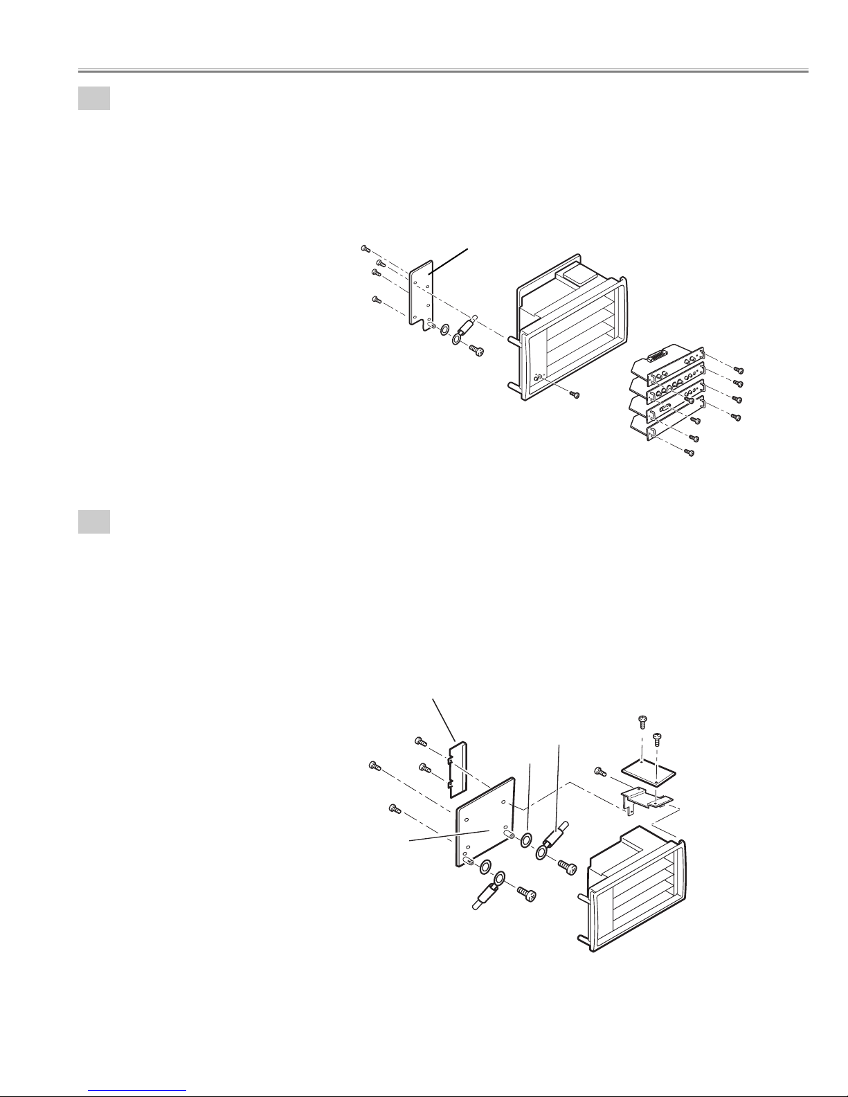
Terminal Slot units disassemblies.
1. Remove 2 screws-A and remove the Lamp net Board.
2. Remove 2 screws-B and remove the Holder-A.
3. Remove 3 screws-C, remove the Holder-B and remove the Mother Board.
4. Remove 2 screws-D, remove 2 washers and remove Grounding Leads from the Mother Board.
(See Fig.4-3)
Mechanical disassemblies
RS232C Board
C
C
C
C
D
B
Terminal Board
units 1-4
A
A
A
A
A
A
A
A
CG Mother Board
C
Holder-B
B
B
C
Washer
Grounding Lead
Grounding Lead
Washer
D
D
A
A
C
Lamp net Board
Holder-A
Panel

- 22 -
Fig.4-5
Fig.4-4
4-5
Terminal Board Component disassemblies.
1. Remove 2 screws-A ,remove 2 screws-B, remove screw-C,remove screw-D and remove the Terminal board
Component.
2. Remove 2 screws-E, remove the Holders and remove the Earth BRKT Slot.
3. Remove 4 screws-G and remove the Handles.
(See Fig.4-5)
4-4
Terminal Board DL-SDI disassemblies.
1. Remove 2 screws-A, remove 4 nuts-B, remove 4 washers-C and remove the Terminal board DL-SDI.
2. Remove 2 screws-D, remove the Holders and remove the Earth BRKT Slot.
3. Remove 4 screws-E and remove the Handles.
(See Fig.4-4)
Mechanical disassemblies
Terminal board Earth
Holder
D
A
A
Holder
D
Earth BRKT Slot
Terminal board Component
D
Panel
Handle
D
Handle
B
B
A
Holder
Earth BRKT Slot
A
G
G
Panel
Holder
Handle
G
G
Handle
C
D
B
B
E
E
- 23 -
4-6
Terminal Board DVI disassemblies.
1. Remove 2 screws-A, remove screw-B, remove screw-C, and remove the Terminal board DVI.
2. Remove 2 screws-D, remove the Holders and remove the Earth BRKT Slot.
3. Remove 4 screws-F and remove the Handles.
(See Fig.4-6)
4
-7
Terminal Board Earth disassemblies.
1. Remove 2 screws-A and remove the Terminal board Earth.
2. Remove 2 screws-B, remove the Holders and remove the Earth BRKT Slot.
3. Remove 4 screws-D and remove the Handles.
(See Fig.4-7)
Fig.4-6
Fig.4-7
Mechanical disassemblies
Terminal board DVI
A
Holder
Holder
F
F
Handle
A
Earth BRKT Slot
Terminal board Earth
F
F
Panel
B
C
D
Handle
D
Holder
D
A
Holder
Earth BRKT Slot
A
D
D
Panel
Handle
D
Handle
B
B
- 24 -
Mechanical disassemblies
4-8
Control Switch unit disassemblies.
1. Remove 4 screws, remove the Control Button and remove the Control Board.
(See Fig.4-8)
Fig.4-8
5-1
Shield plates removal.
1. Remove screws-A, and remove the grounding lead.
2. Remove 2 screws-B, remove 2 screws-C and remove the shield plate.
( Do not remove the Lens shift unit screw. Otherwise the Lens shift mechanism is damaged.
Warning:
Do not remove the screw.
Shield plate
Fig.5-1
Fig.5-1a
Control Button
Control Board
Control Panel
Grounding Lead
A
B
B
C
C
- 25 -
Mechanical disassemblies
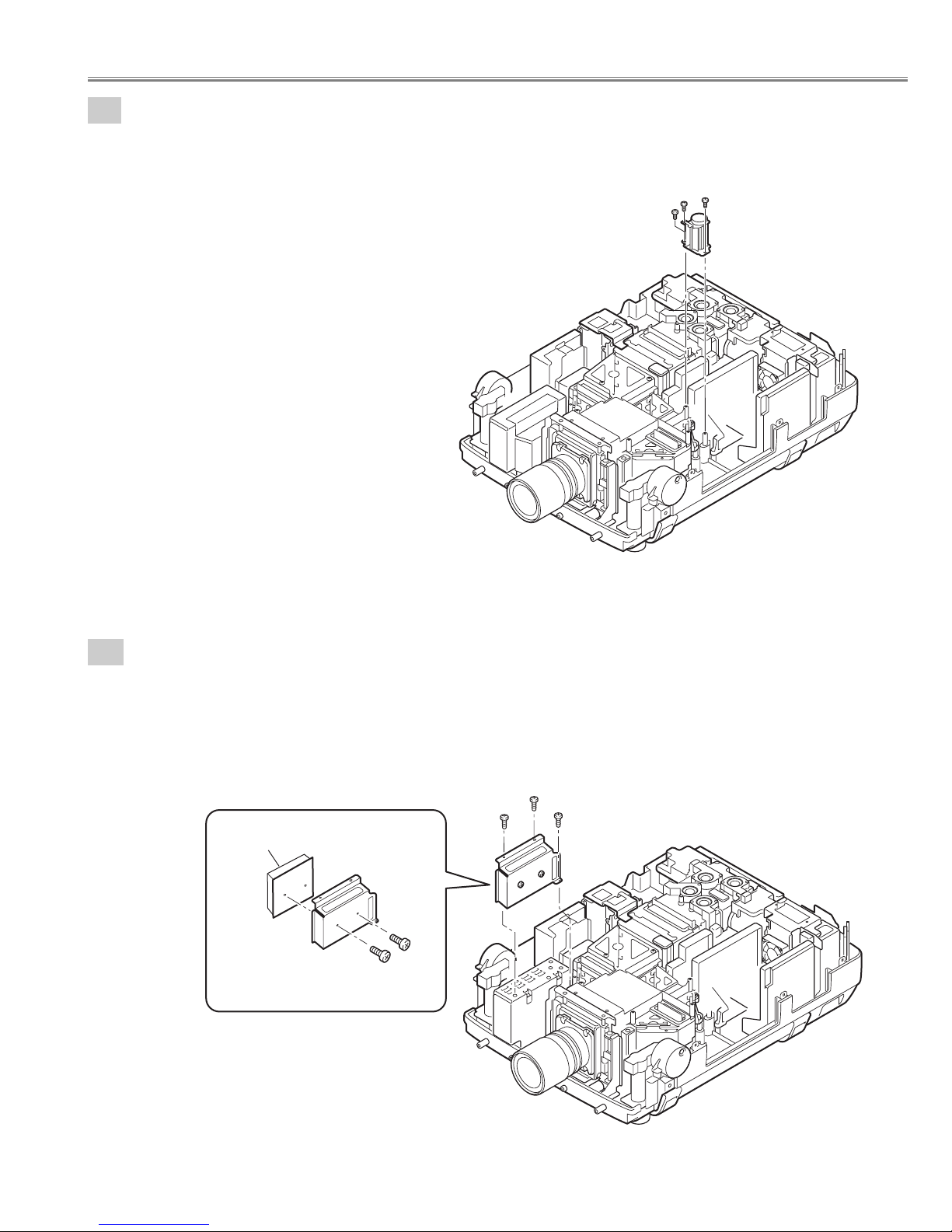
5-3
Switch Power Supply unit(5V) removal.
1. Remove 2 screws-A, remove screw-B and remove the Switch power supply(5V) unit .
2. Remove 2 screws-c and remove the Switch power supply(5V) Board.
(See Fig.5-31, 5-3a)
Fig.5-3
Fig.5-3a
5-2
Fan(FN901) removal.
1. Remove 3 screws-A and remove the Fan(FN901).
(See Fig.5-2)
Fig.5-2
A
A
A
Fan(FN901)
Switch Power Supply(5V) Board
Holder
C
A
A
C
B
Switch Power Supply(5V) unit
- 26 -
Mechanical disassemblies
A
A
A
Grounding
Lead
Grounding
Lead
Grounding Lead
Washer
Washer
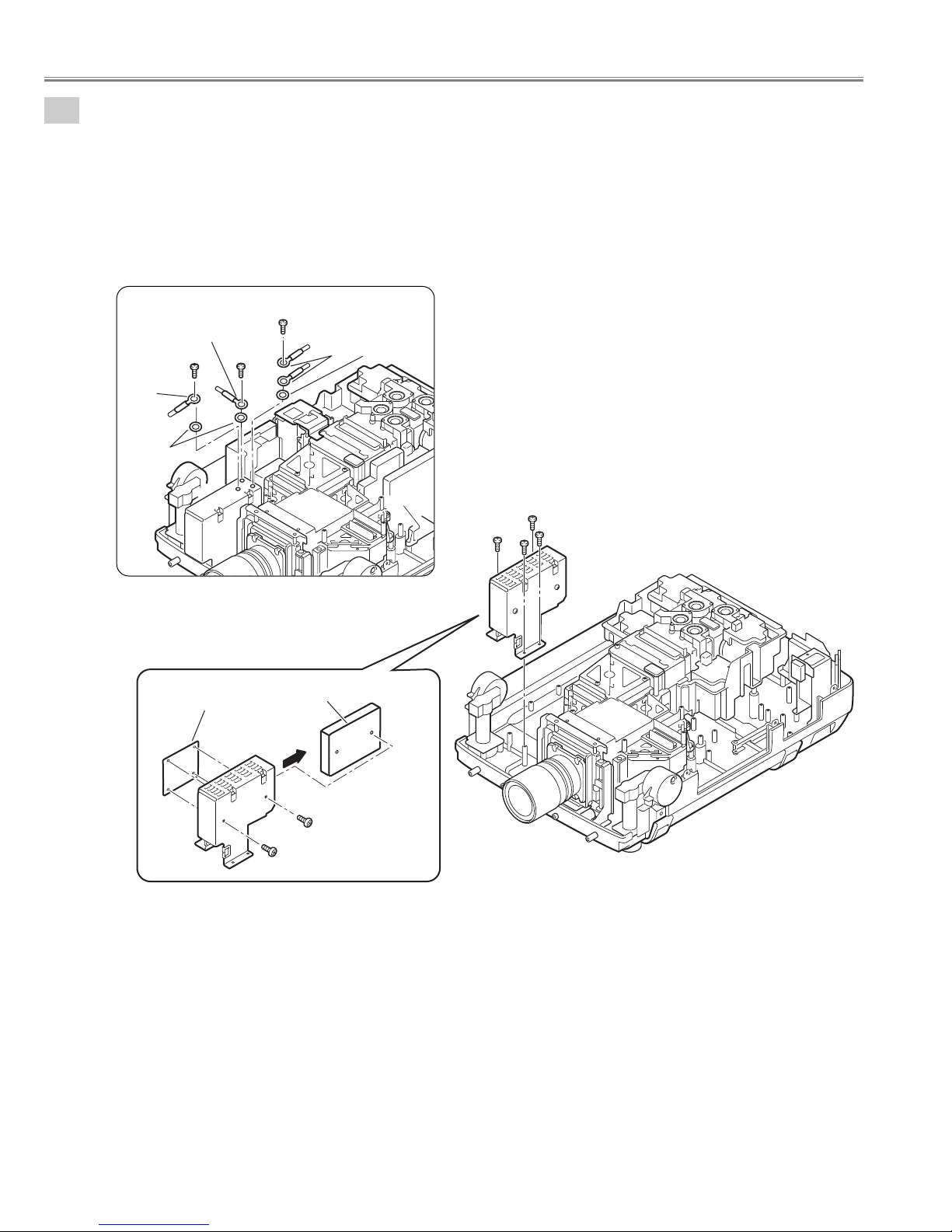
5-4
Switch Power Supply(25V) unit removal.
Fig.5-4
Fig.5-4a
Fig.5-4b
1. Remove 3 screws-A, remove 3 washers and remove the grounding leads. (See Fig.5-4b)
2. Remove 4 screws-B, and remove the Switch power supply(25V) unit.
3. Remove 2 screws-C and remove the Switch power supply(25V)Board.
4. Unhook the 4 Fixer Clamps and remove the Motor &Audio Board.
(See Fig.5-4, 5-4a, 5-4b)
Motor and Audio
Board
The Motor and Audio Board is fixed with
holder by hook. (4places)
Switch Power Supply (25V)
Board
C
C
SW-Power supply unit(25V)
B
B
B
B
- 27 -
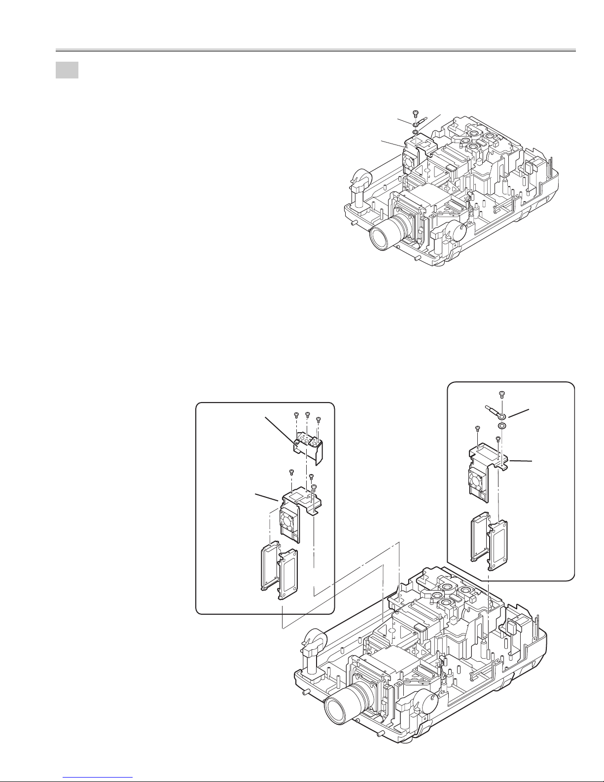
5-5
Lamp Ballast Units removal.
1. Remove screw-C and remove the grounding lead. (Lamp ballast 3-4 unit. See Fig.5-5)
Fig.5-5
Fig.5-5
Fig.5-5a
Fig.5-5b
Mechanical disassemblies
2. Remove screw-A and remove the grounding lead from the Holder. (Lamp ballast 1-2 units. See Fig.5-5a)
3. Remove 2 screws-B and remove the Holder-D.
4. Remove the Lamp Ballast Unit1 and Lamp Ballast Unit2.
5. Remove 3 screws-F and remove the Holder-F.
6. Remove 2 screws-D, remove screw-E and remove the Holder-E.
7. Remove the Lamp Ballast Unit3 and Lamp Ballast Unit4.
(See Fig.5-5, 5-5a, 5-5b,)
Grounding
Lead
Lamp ballast
3-4 unit
C
Washer
Holder -F
Holder -E
Ballast4
Lamp ballast 3-4
units
F
D
F
F
D
E
Ballast3
Ballast2
A
Grounding Lead
B
Washer
B
Ballast1
Lamp ballast 1-2
units
Holder -D
- 28 -
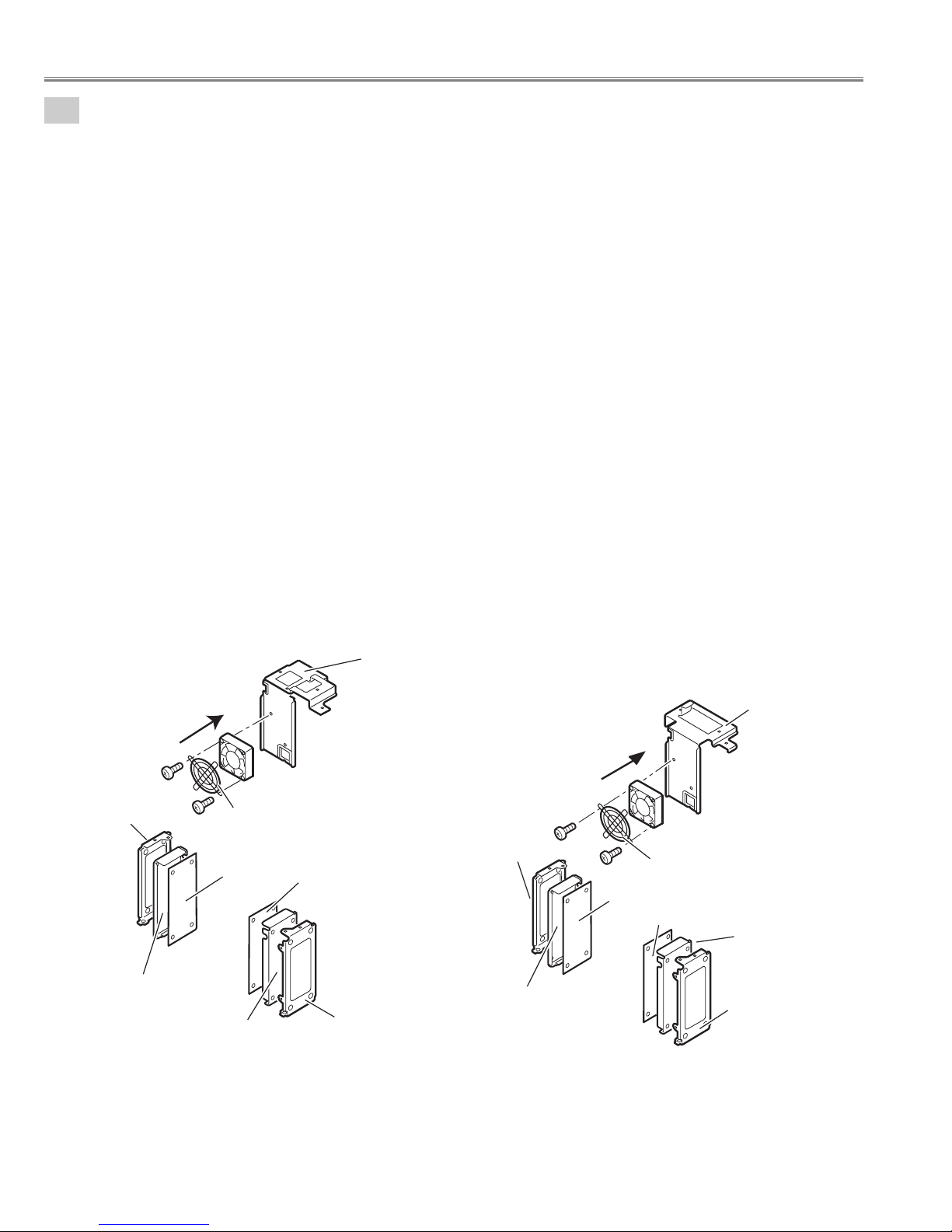
Note;
Mark the Fans as they are removed from the holder so that they may be reassembled in the same
location from which they were removed. Be careful of the attachment direction of Fans.
See arrow mark in a figure.
Ballast units may be reassembled in the same location and direction from which they were removed.
Be careful of the attached direction of Ballast units.
Lamp Ballast Units 1-2
1. Remove 2 screws-A, remove the Fan(FN908) and FAN Guard.
2. Remove Lamp Ballast unit 1 and remove the Spacer.
(Unhook the Fixer Clamp and remove the Lamp Ballast unit .)
3. Remove Lamp Ballast unit 2 and Spacer.
(Unhook the Fixer Clamp and remove the Lamp Ballast unit .)
(See Fig.5-6a)
Lamp Ballast Units 3-4
4. Remove 2 screws-B, remove the Fan(FN907) and FAN Guard.
5. Remove Lamp Ballast unit 3 and Spacer.
(Unhook the Fixer Clamp and remove the Lamp Ballast unit .)
6. Remove Lamp Ballast unit 4 and remove the Spacer.
(Unhook the Fixer Clamp and remove the Lamp Ballast unit .)
(See Fig.5-6b)
5-6
Lamp Ballast Units disassemblies.
Fig.5-6aFig.5-6b
Mechanical disassemblies
Holder -C
Spacer
The direction
of a wind.
(FN907)
B
Ballast 4
FN907
FAN GUARD
B
Spacer
Ballast 3
Holder
Holder -E
A
Holder-C
Spacer
The Ballast Board is being fixed with
Holder by hook. (4places)
The direction
of a wind.
(FN908)
A
Ballast 2
Holder-D
FN908
FAN GUARD
Ballast 1
Spacer
Holder-C
- 29 -
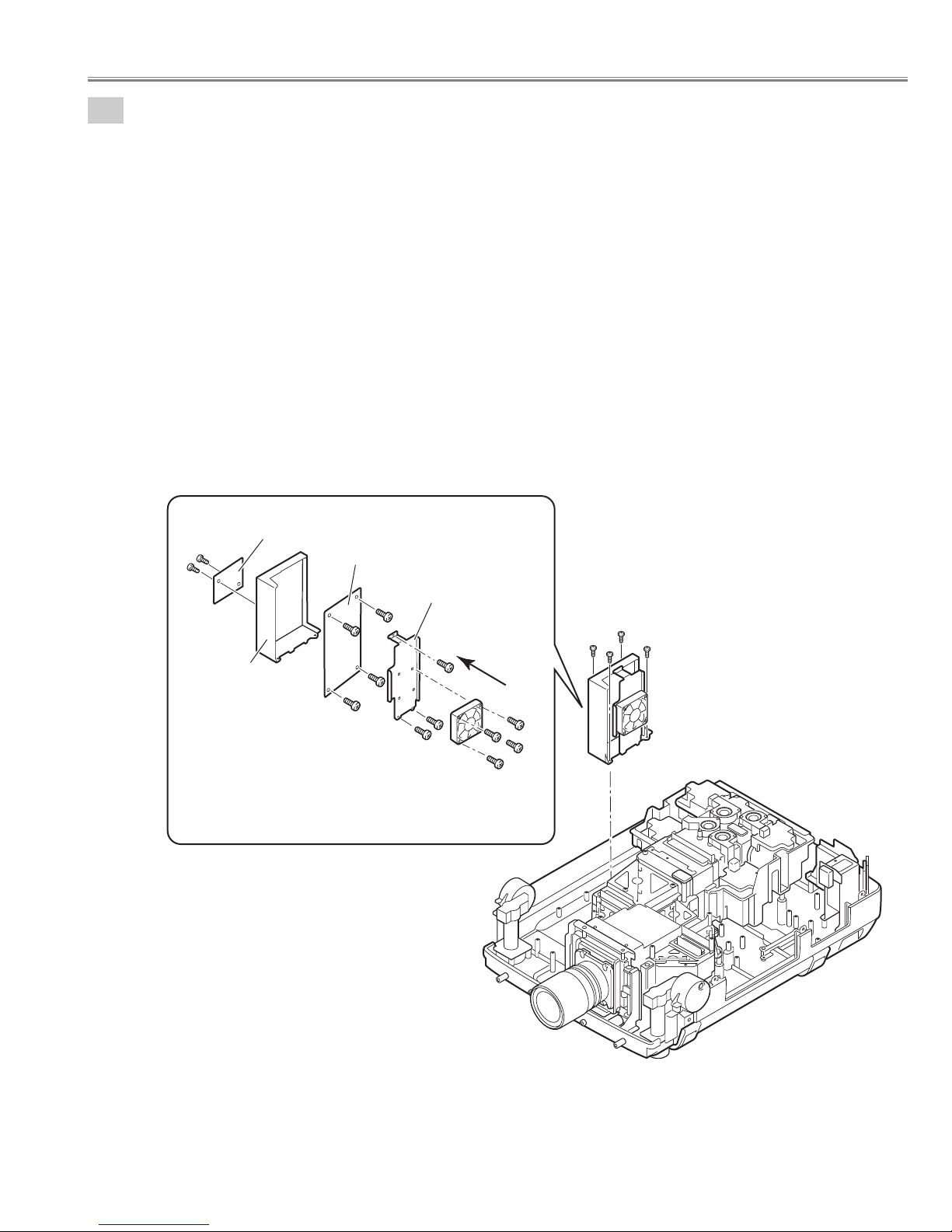
5-7
PFC Unit 3-4 and Power Unit removal.
PFC Unit 3-4 removal.
1. Remove 4 screws-A and remove the PFC 3-4 Unit.
2. Remove 4 screws-B and remove the Fan (FN914).
3. Remove 3 screws-C and remove the Holder FN.
4. Remove 4 screws-D and remove the PFC 3-4 Board.
5. Remove 2 screws-E and remove the AC4 net Board.
(See Fig.5-7, 5-7a)
Note;
Mark the Fans as they are removed from the holder so that they may be reassembled in the same location from
which they were removed. Be careful of the attached direction of Fan.
See arrow mark in a figure.
PWB units may be reassembled in the same location and direction from which they were removed. Be careful of
the attached direction of PWB units.
Fig.5-7
Fig.5-7a
Mechanical disassemblies
E
E
AC net Board
Holder PFC
PFC3-4 Board
D
D
D
D
Holder FN
C
C
The direction
of a wind.
(FN914)
C
B
B
A
A
B
A
A
PFC3-4 unit
B
- 30 -
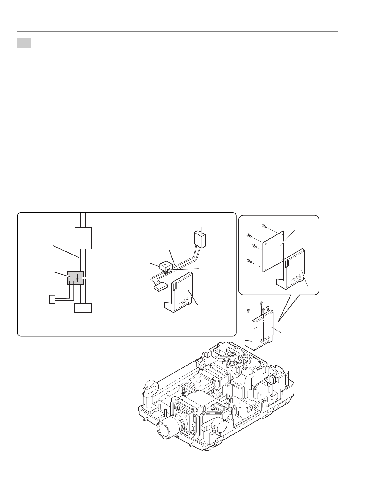
5-8
Current sensor removal and replacement.
(Current sensor is used only for PLV-HD2000E.)
Power unit
Ass'y Power unit
K6A
Current sensor
Current
sensor
K
L
K96W
Noise Filter
LF901
Blue lead wire
Blue lead wire
K6A
LF901
Printed mark
A903
(a)
1. Unhook the part(a) and remove the current sensor.
Note:The way of installing a current sensor is very important on the performance and the safety. Install in the
condition which is the same as the time of disassemble.
Replacement
1. The Current sensor is attached in the blue lead wire between an interlock switch (SW902) and power unit
(K6A).
2. The Current sensor (L) side is attached in the K6A side.
Refer to schematic diagrams (page-S1).
PWB units may be reassembled in the same location and direction from which they were removed. Be careful of the
attached direction of PWB units.
Power Unit removal.
Power Unit removal.
1. Remove 2 screws-A, remove 2 screws-B and remove the Power Unit.
2. Remove 4 screws-C and remove the Power Board.
(See Fig.5-8, 5-8a)
Fig.5-8b
Fig.5-8a
Fig.5-8
Mechanical disassemblies
C
C
C
C
Power Board
Holder Power
A
B
B
A
Power unit
 Loading...