

Page 1

EXPAND SERIAL COMMAND
FUNCTIONAL SPECIFICATIONS
PLV-HD2000
SANYO Electric Co., Ltd
Home Electronics Group
AV Company
Projector Business Unit
Page 2

PLV-HD2000 Expand Serial Command Functional Specifications
CONTENTS
1. Overview ...................................................................................................................... 4
2. Serial Interface Specification ..................................................................................... 4
2.1. Communication Specification................................................................................. 4
2.2. Connection ............................................................................................................... 4
3. Note for communication............................................................................................. 5
4. Name Definition........................................................................................................... 5
5. Functional Execution Command Table...................................................................... 6
5.1. Image Command Table ............................................................................................ 6
5.2. Display Command Table.......................................................................................... 6
5.3. Input Control Command Table ................................................................................ 6
5.4. Screen Command Table........................................................................................... 7
5.5. Lamp Command Table............................................................................................. 7
5.6. Setting Command Table .......................................................................................... 7
6. Status Read Command Table ..................................................................................... 8
6.1. Image Status Read Command Table....................................................................... 8
6.2. Display Status Read Command Table .................................................................... 8
6.3. Video Status Read Command Table ....................................................................... 8
6.4. Input Status Read Command Table ........................................................................ 9
6.5. Screen Status Read Command Table..................................................................... 9
6.6. Lamp Status Read Command Table........................................................................ 9
6.7. Setting Status Read Command Table................................................................... 10
6.8. Other Status Read Command Table...................................................................... 10
7. Error Code Table........................................................................................................ 10
8. Functional Execution Command.............................................................................. 11
8.1. Format..................................................................................................................... 11
8.2. Transfer Example................................................................................................... 11
8.3. Operation Requirements ....................................................................................... 11
8.4. Image Command .................................................................................................... 12
8.5. Display Control Command.................................................................................... 17
8.6. Input Control Command........................................................................................ 22
8.7. Screen Control Command..................................................................................... 25
8.8. Lamp Command..................................................................................................... 27
8.9. Setting Command .................................................................................................. 28
9. Status Read Command............................................................................................. 32
9.1. Format..................................................................................................................... 32
9.2. Transfer Example................................................................................................... 32
9.3. Image Status Read Command............................................................................... 33
9.4. Display Status Read Command ............................................................................ 36
2/56
Page 3

PLV-HD2000 Expand Serial Command Functional Specifications
9.5. Status Read Command for Video.......................................................................... 38
9.6. Input Status Read Command................................................................................ 39
9.7. Screen Status Read Command............................................................................. 45
9.8. Lamp Status Read Command................................................................................46
9.9. Setting Status Read Command............................................................................. 48
9.10. Other Status Read Command.............................................................................. 51
10. Command with Address Specification ..................................................................54
10.1. Overview............................................................................................................... 54
10.2. Functional Execution Command with address.................................................. 55
10.3. Status Read Command with Address................................................................. 56
3/56
Page 4
PLV-HD2000 Expand Serial Command Functional Specifications
1. Overview
・ This Functional Specification defines communication functions to Network card for PLV-HD2000.
・ The Commands are designed to communicate with Network board, but most commands can be
used to remote-control a projector through RS-232C from a computer. Therefore these commands
are defined as Expand Serial Commands.
・ When using commands with address, refer to [10.Command with Address Specification].
2. Serial Interface Specification
2.1. Communication Specification
Items Specification
Synchronoun System Asynchronous
Transmission Speed 9600 / 19200
Data Length 8 bits
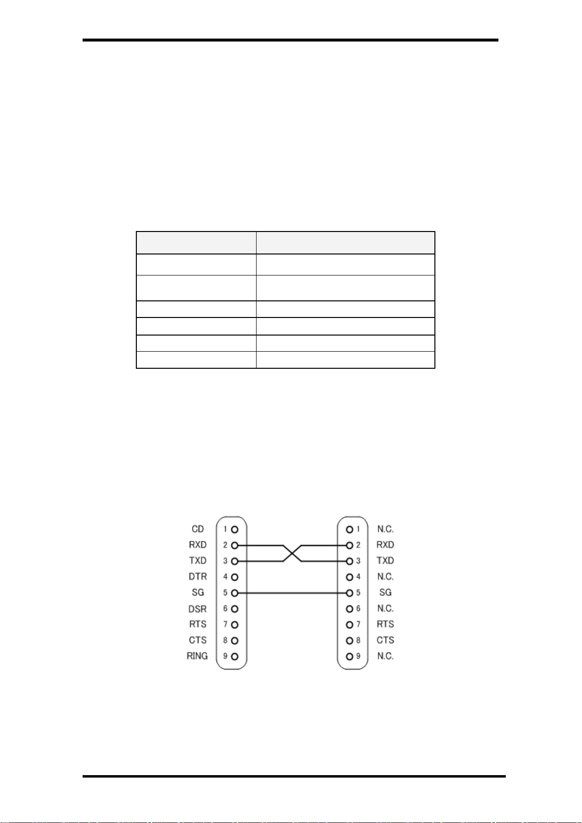
2.2. Connection
Dedicated serial cables that come with the projector must be used for the connection between a
computer and the projector.
Parity N/A
Stop Bit 1
Flow Control N/A
Note1) Transmission speed: initial setting value is 19200
Note2) Transmission speed can be changed in Service Mode
PC Projector
COM 1 Serial Port IN
(D-Sub 9Pin) (D-Sub 9Pin)
Connect COM port of a computer to SERIAL PORT IN of a projector.
COM Port (COM1 or COM2) of a computer is specified by the control software of the computer.
4/56
Page 5
PLV-HD2000 Expand Serial Command Functional Specifications
3. Note for communication
・ Expand Serial Command is defined as a single command per line that starts with “C” and ends with
carriage return (0x0D).
・ When a projector receives carriage return (0x0D), it starts decoding.
・ There are two types of commands as below:
-Example of Functional Execution Command: ”CF_BRIGHT_032” [CR]
-Example of Status Read Command: “CR_BRIGHT” [CR]
Note) “_” indicates a space
・ Projector clears the information of buffer in the following cases:
-When the projector receives LF(0x0A) or EOF(0x1A).
-When it takes more than one second to receive a single command
(Until receiving the carriage return after the reception of the first data)
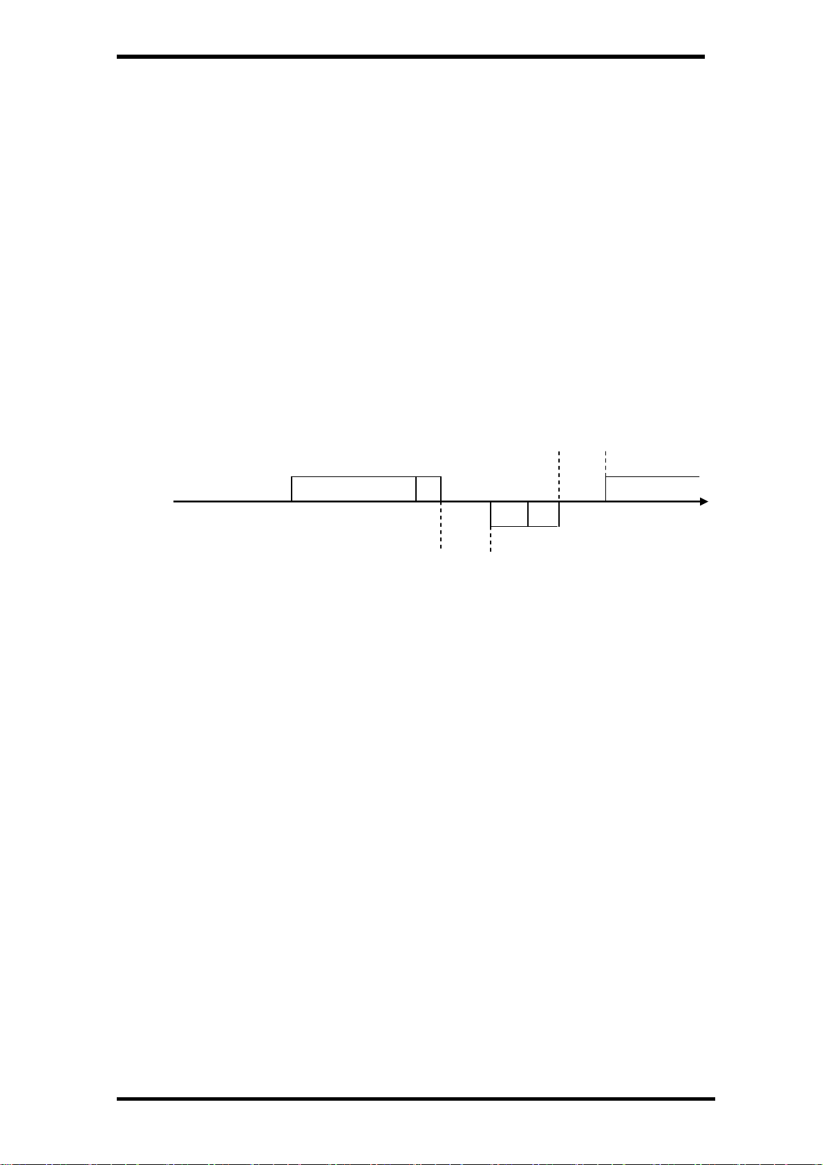
・ When executing several commands in a row, allow 100 ms from the reception of the response to the
previous command.
More than 100 ms
Command
PC → Projector “CF_BRIGHT_032” CR Next Command
Projector → PC “000” CR
Response
(A few ms ~ 5s)
* When the command is sent without waiting for the response to the previous command, the
projector may not operate properly.
* Howerver this is not the case when there is no response for more than 5 seconds.
・ Projector takes about 5 seconds for internal initialization after plugging in AC power. During this time
projector cannot process commands. Do not issue any command.
・ Serial Commands are invalid when Service Mode or Special menu is displayed.
4. Name Definition
・ Data from a controller to a projector is represented as COMMAND, and data from a projector to a
controller for the incoming command is represented as RESPONSE.
・ [CR]: Carriage Return Code
The command ends with carriage return code.
Response also ends with carriage return code.
・ _: Space Code
All space code is expressed by (_).
・ %1: Parameter included in Command
When there is more than one parameter, they are defined as %2, %3…
・ %%%: Error Code from a projector
Acceptable: “000”
Unacceptable: Refer to [7.Error Code Table“ for the error number
5/56
Page 6
PLV-HD2000 Expand Serial Command Functional Specifications
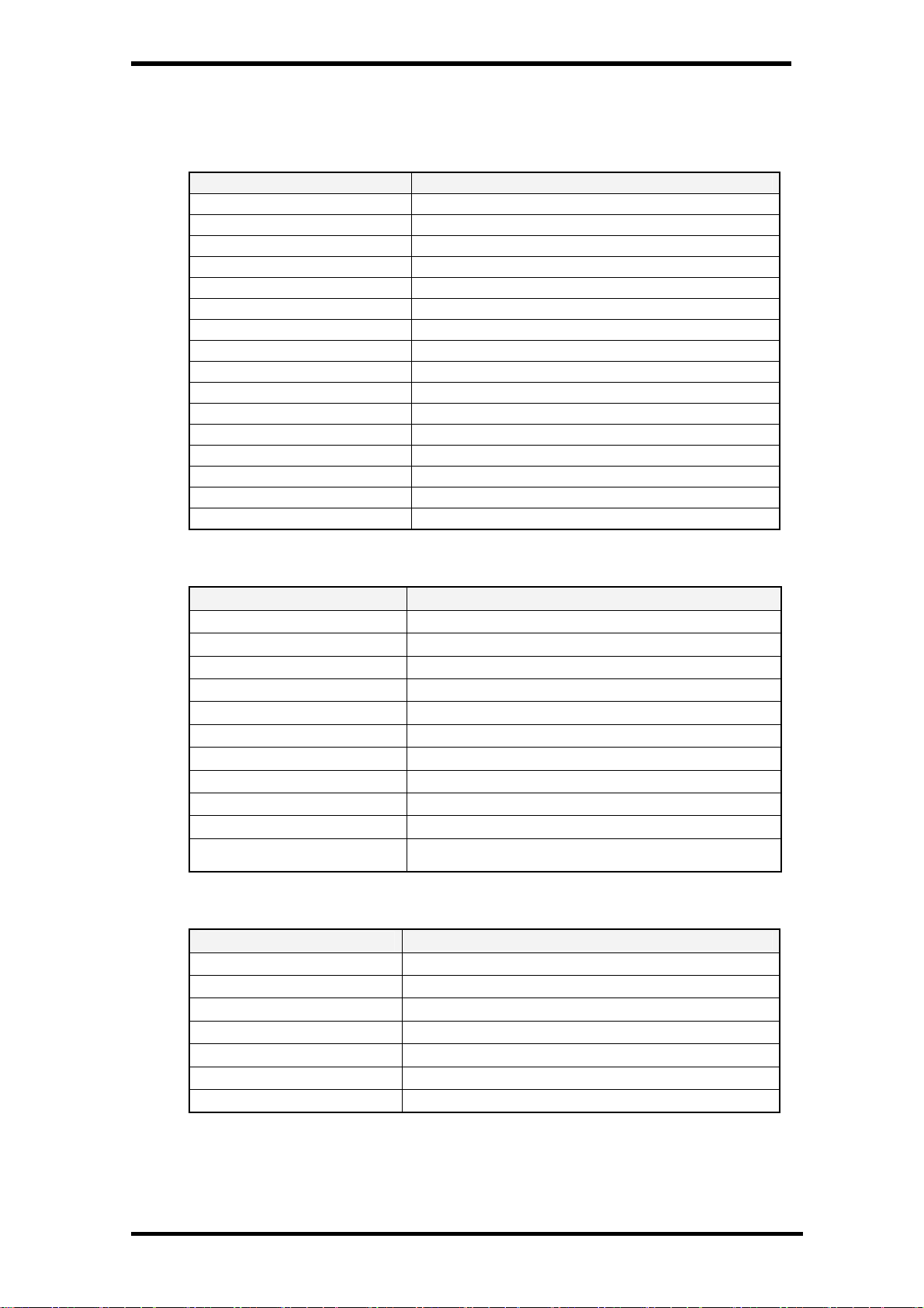
5. Functional Execution Command Table
5.1. Image Command Table
Execute command Item
CF_BRIGHT_%1 [CR]
CF_CONT_%1 [CR]
CF_COLOR_%1 [CR]
CF_TINT_%1 [CR]
CF_SHARP_%1 [CR]
CF_GAMMA_%1 [CR]
CF_WBAL-R_%1 [CR]
CF_WBAL-G_%1 [CR]
CF_WBAL-B_%1 [CR]
CF_COLTEMP_%1 [CR]
CF_NZRED_%1 [CR]
CF_PROGV_%1 [CR]
CF_IMAGE_%1 [CR]
CF_IMAGEADJ_%1 [CR]
CF_APCTRL_%1 [CR]
CF_BBAL_%1_%2_%3 [CR]
Set value of Brightness
Set value of Contrast
Set value of Color
Set value of Tint
Set value of Sharpness
Set value of Gamma
Set Red value of White Balance
Set Green value of White Balance
Set Blue value of White Balance
Set value of Color Temp.
Set / Cancel Noise reduction
Set / Cancel Progressive
Set Image mode
Reset / Store adjusted values of Image
Set level of Auto Picture Control
Set value of Gamma Balance
5.2. Display Command Table
Execute command Item
CF_FSYNC_%1 [CR]
CF_TODOTS_%1 [CR]
CF_CLAMP_%1 [CR]
CF_H-POS_%1 [CR]
CF_V-POS_%1 [CR]
CF_DLINE_%1 [CR]
CF_DDOTS_%1 [CR]
CF_SETDISPADJ_%1 [CR]
CF_ORGMODE_%1 [CR]
CF_MODESTORE_%1 [CR]
CF_MODEFREE_%1 [CR]
5.3. Input Control Command Table
Execute command
CF_INPUT_%1 [CR]
CF_SOURCE_%1 [CR]
CF_INPUT1_%1 [CR]
CF_INPUT2_%1 [CR]
CF_INPUT3_%1 [CR]
CF_INPUT4_%1 [CR]
CF_SYSTEM_%1 [CR]
Set value of Fine Sync
Set value of Total Dots
Set value of Clamp
Set value of Horizontal Position
Set value of Vertical Position
Set value of Display Line
Set value of Display Dots
Apply values set in PC Adj menu to screen image
Specify the original signal of the Display mode
Store values set in Display adjust menu to Mode %1
Clear values stored in Mode %1 and return it to Free
status
Item
Select Input %1
Select Input Source %1
Select Input 1 and Source %1
Select Input 2 and Source %1
Select Input 3 and Source %1
Select Input 4 and Source %1
Select System %1
6/56
Page 7

PLV-HD2000 Expand Serial Command Functional Specifications
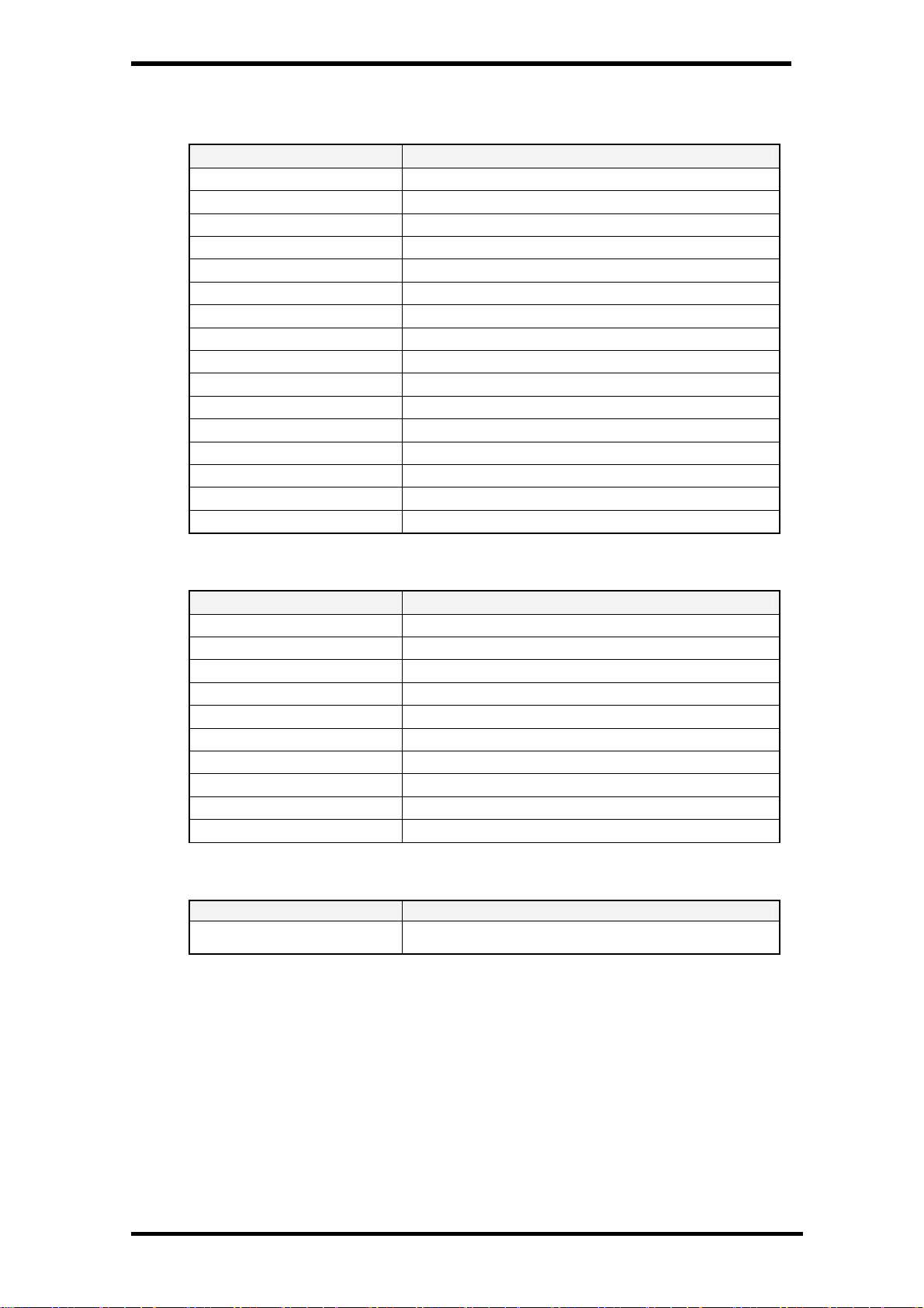
5.4. Screen Command Table
Execute command Item
CF_SCREEN_%1 [CR]
CF_VSCALE_%1 [CR]
CF_VPOS_%1 [CR]
CF_HSCALE_%1 [CR]
CF_HPOS_%1 [CR]
Select Screen size
Set value of V Scale
Set value of V Position
Set value of H Scale
Set value of H Position
5.5. Lamp Command Table
Execute command Item
CF_LAMPH_%1 [CR]
CF_LAMPMODE_%1 [CR]
CF_AUTOLAMPCONTRL_%1 [CR]
Reset total running time of each lamp
Select lamp mode (Full/Half)
Switch ON/OFF of auto lamp control
5.6. Setting Command Table
Execute command Item
CF_BBACK_1 [CR]
CF_DISP_%1 [CR]
CF_LOGO_%1 [CR]
CF_CEIL_%1 [CR]
CF_REAR_%1 [CR]
CF_RCODE_%1 [CR]
CF_LANG_%1 [CR]
CF_ON-STA_%1 [CR]
CF_P-MANE_%1 [CR]
CF_P-MANETIME_%1 [CR]
CF_FANSPEED_%1 [CR]
CF_KEYDIS_%1 [CR]
CF_FDEFAULT_%1 [CR]
Set / Cancel Blue Back function
Set / Cancel Display function
Set / Cancel Logo function
Set / Cancel Ceiling function
Set / Cancel Rear function
Select Remote Control Code
Select language for OSD
Set Power ON Start function
Set mode of Power Management
Set value of Power Management timer
Select level of Fan Speed
Set limitation of RC / KEY use
Set values to Factory Default setting
7/56
Page 8
PLV-HD2000 Expand Serial Command Functional Specifications
6. Status Read Command Table
6.1. Image Status Read Command Table
Status read command Item
CR_BRIGHT [CR]
CR_CONT [CR]
CR_COLOR [CR]
CR_TINT [CR]
CR_SHARP [CR]
CR_GAMMA [CR]
CR_WBAL-R [CR]
CR_WBAL-G [CR]
CR_WBAL-B [CR]
CR_COLTEMP [CR]
CR_NZRED [CR]
CR_PROGV [CR]
CR_IMAGE [CR]
CR_IMGGMD [CR]
CR_APCTRL [CR]
CR_BBAL [CR]
Get value of Brightness
Get value of Contrast
Get value of Color
Get value of Tint
Get value of Sharpness
Get value of Gamma
Get Red value of White Balance
Get Green value of White Balance
Get Blue value of White Balance
Get setting status of Color temperature
Get setting status of Noise reduction
Get setting status of Progressive
Get selected Image mode
Get selected Image Gamma mode
Get setting status of Auto Picture Control
Get setting status of Gamma Balance
6.2. Display Status Read Command Table
Status read command Item
CR_FSYNC [CR]
CR_TDOTS [CR]
CR_CLAMP [CR]
CR_H-POS [CR]
CR_V-POS [CR]
CR_DLINE [CR]
CR_DDOTS [CR]
CR_ORGMODE [CR]
CR_MODESTORE [CR]
CR_SETDISPADJ[CR]
Get value of Fine Sync
Get value of Total Dots
Get value of Clamp
Get value of Horizontal Position
Get value of Vertical Position
Get value of Display Line
Get value of Display Dots
Get the original signal of the Display mode
Get Free or Stored status for Display Adj. Mode 1-20
Get signal types currently displayed in System menu.
6.3. Video Status Read Command Table
Status read command Item
CR_SERSYS [CR]
Get currently selected signal. When in Auto mode, it
returns a result by Auto detect
8/56
Page 9
PLV-HD2000 Expand Serial Command Functional Specifications
6.4. Input Status Read Command Table
Status read command Item
CR_INPUT [CR]
CR_SOURCE [CR]
CR_SRCINP1 [CR]
CR_SRCINP2 [CR]
CR_SRCINP3 [CR]
CR_SRCINP4 [CR]
CR_SYSTEM [CR]
CR_SYSLIST [CR]
CR_MODELIST [CR]
CR_HMSLOT [CR]
CR_NMSLOT1 [CR]
CR_NMSLOT2 [CR]
CR_NMSLOT3 [CR]
CR_NMSLOT4 [CR]
CR_IDSLOT1 [CR]
CR_IDSLOT2 [CR]
CR_IDSLOT3 [CR]
CR_IDSLOT4 [CR]
Get selected Input No
Get selected Input Source
Get selected source for Input 1
Get selected source for Input 2
Get selected source for Input 3
Get selected source for Input 4
Get selected System in the Input mode
Get possible system list
Get possible mode list
Get the total number of inputs
Get Slot board name inserted to Input 1
Get Slot board name inserted to Input 2
Get Slot board name inserted to Input 3
Get Slot board name inserted to Input 4
Get Slot board ID inserted to Input 1
Get Slot board ID inserted to Input 2
Get Slot board ID inserted to Input 3
Get Slot board ID inserted to Input 4
6.5. Screen Status Read Command Table
Status read command Item
CR_SCREEN [CR]
CR_VSCALE [CR]
CR_VPOS [CR]
CR_HSCALE [CR]
CR_HPOS [CR]
Get selected screen size
Get value of V Scale
Get value of V Position
Get value of H Scale
Get value of H Position
6.6. Lamp Status Read Command Table
Status read command Item
CR_LAMPREPL [CR]
CR_LAMPMODE [CR]
CR_AUTOLAMPCONTRL [CR]
CR_LAMPSTS [CR]
CR_INFLAMP [CR]
CR_PROJH [CR]
CR_HMLAMP [CR]
Get the information on Lamp replacement time
Get selected Lamp mode
Get selected Lamp Control mode
Get the information on Lamp lighting status
Get Lamp switching status
Get total running time of the projector
Get the total number of lamps
9/56
Page 10

PLV-HD2000 Expand Serial Command Functional Specifications
6.7. Setting Status Read Command Table
Status read command Item
CR_BBACK [CR]
CR_DISP [CR]
CR_LOGO [CR]
CR_RCODE [CR]
CR_LANG [CR]
CR_ON-STA [CR]
CR_P-MANE [CR]
CR_P-MANETIME [CR]
CR_FANSPEED [CR]
CR_KEYDIS [CR]
Get setting status of Blue Back
Get setting status of Display
Get setting status of Logo
Get selected Remote Control Code
Get selected language
Get setting status of ON Start
Get setting status of Power Management
Get setting time for Power Management
Get selected Fan Control Speed level
Get limitation status of RC/KEY use
6.8. Other Status Read Command Table
Status read command Item
CR_PRESSURE [CR]
CR_SIGNAL [CR]
CR_VMUTE [CR]
CR_FREEZE [CR]
CR_INFPFAIL [CR]
CR_TEMPWARN [CR]
CR_TEMPFAIL [CR]
Get Air Pressure data
Get Signal status if there is signal or not
Get setting status of No Show
Get setting status of Freeze
Get the information on Power Failure
Get temperature status whether it is close to abnormmal level
or not
Get temperature in abnormal temperature status
7. Error Code Table
Error Code Contents
000 Normal reception (Not error)
101 The function is invalid in the selected mode
102 The selected value is out of range (The value is not
103 The command is not available to the hardware (the
? -When the received data cannot be decoded
-Parameter determination error (digit number error,
including invalid value)
be applied)
command is for the optional function which is not
supported by the given hardware)
10/56
Page 11

PLV-HD2000 Expand Serial Command Functional Specifications
8. Functional Execution Command
8.1. Format
1. PC issues a command in the format below:
Pattern1: “CF _ Command” [CR]
Pattern2: “CF _ Command _” %1 [CR]
CF_: Header
Command: String
%1: Parameter (string)
_: Space (To separate Command and Parameter)
2. The projector decodes the received data and when it gets ready to receive the next
command, it returns the response.
“000” [CR]: (0x06 ,0x0D) When receiving Function Execution Command
“nnn” [CR]: Except “000”, when it cannot execute commands for some specific reason
For details, refer to [7. Error Code Table
3. When the received data cannot be decoded, the projector returns
“ ? “ [CR]
8.2. Transfer Example
When setting total dots for the projector to 1344 by Expand Serial Command
PC → PJ: “CF_TODOTS_1344” [CR]
PC ← PJ: “000” [CR] ---------------- Acceptable
8.3. Operation Requirements
Functional Execution Command is limited when the projector is in the following status.
However, Status Read Command is effective under these conditions.
Projector Status Valid Function Execution Command
In Standby mode C00: POWER ON
Count Down in process
Cooling Down in process N/A
Cooling Down due to abnormal temperature N/A
C00: POWER ON
(Count Down is terminated)
Abnormal Temperature N/A
Power Failure
(60 seconds after Power failed)
Power Management / Cooling Down in
process
Power Management in process
Note) When the projector receives the other command in the above status, it returns error code
of showing the status.
N/A
N/A
C00: POWER ON
C01: POWER OFF
11/56
Page 12
PLV-HD2000 Expand Serial Command Functional Specifications
8.4. Image Command
8.4.1. CF_ BRIGHT Command
Command “CF_BRIGHT_%1” [CR]
“000-063” --------- Directly specify setting value of Brightness
%1
Details
Response
“UP” ---------------- Increment setting value of Brightness by 1
“DN” ---------------- Decrement setting value of Brightness by 1
Set Brightness value (valid only when it is in the normal Power ON status)
The value set by this command is not stored in the projector’s memory.
Therefore, when the power is turned to ALL OFF status, the value returns to the
original setting. (It is stored in Standby mode.)
Acceptable “000” [CR]
Unacceptable “Error Code” [CR]
8.4.2. CF_CONT Command
Command “CF_CONT_%1” [CR]
“000-063” --------- Directly specify setting value of Contrast.
%1
Details
Response
“UP” ---------------- Increment setting value of Contrast by 1.
“DN” ---------------- Decrement setting value of Contrast by 1.
Set Contrast value (valid only when it is in the normal Power ON status)
The value set by this command is not stored to the projector’s memory.
Therefore, when the power is turned to ALL OFF status, the value returns to the
original setting. (It is stored in Standby mode.)
Acceptable “000” [CR]
Unacceptable “Error Code” [CR]
8.4.3. CF_COLOR Command
Command “CF_COLOR_%1” [CR]
“000-063” --------- Directly specify setting value of Color.
%1
Details
Response
“UP” ---------------- Increment setting value of Color by 1.
“DN” ---------------- Decrement setting value of Color by 1.
Set Color value (valid only when it is in the normal Power ON status)
The value set by this command is not stored in the projector’s memory.
Therefore, when the power is turned to ALL OFF status, the value returns to the
original setting. (It is stored in Standby mode.)
Acceptable “000” [CR]
Unacceptable “Error Code” [CR]
8.4.4. CF_TINT Command
Command “CF_TINT_%1” [CR]
“000-063” --------- Directly specify setting value of Tint.
%1
Details
Response
“UP” ---------------- Increment setting value of Tint by 1.
“DN” ---------------- Decrement setting value of Tint by 1.
Set Tint value (valid only when it is in the normal Power ON status)
The value set by this command is not stored in the projector’s memory.
Therefore, when the power is turned to ALL OFF status, the value returns to the
original setting. (It stays in Standby mode.)
Acceptable “000” [CR]
Unacceptable “Error Code” [CR]
12/56
Page 13

PLV-HD2000 Expand Serial Command Functional Specifications
8.4.5. CF_SHARP Command
Command “CF_SHARP_%1” [CR]
“000-015” --------- Directly specify setting value of Sharpness.
%1
Details
Response
“UP” ---------------- Increment setting value of Sharpness by 1.
“DN” ---------------- Decrement setting value of Sharpness by 1.
Set Sharpness value (valid only when it is in the normal Power ON status)
The value set by this command is not stored in the projector’s memory.
Therefore, when the power is turned to ALL OFF status, the value returns to the
original setting. (It is stored in Standby mode.)
Acceptable “000” [CR]
Unacceptable “Error Code” [CR]
8.4.6. CF_GAMMA Command
Command “CF_GAMMA_%1” [CR]
“000-015” ---------- Directly specify setting value of Gamma.
%1
Details
Response
“UP” ----------------- Increment setting value of Gamma by 1.
“DN” ----------------- Decrement setting value of Gamma by 1.
Set Gamma value (valid only when it is in the normal Power ON status)
The value set by this command is not stored in the projector’s memory.
Therefore, when the power is turned to ALL OFF status, the value returns to the
original setting. (It is stored in Standby mode.)
Acceptable “000” [CR]
Unacceptable “Error Code” [CR]
8.4.7. CF_WBAL- Command
Command “CF_WBAL-%1_%2” [CR]
“R” ------------- RED
%1
%2
Details
Response
“G” ------------- GREEN
“B” ------------- BLUE
“000-063” ----- Directly specify value of color set in %1.
“UP” ------------ Increment value of color set in %1 by 1.
“DN” ------------ Decrement color value set in %1 by1.
Set value of color specified by White Balance %1
(valid only when it is in the normal Power ON status)
The value set by this command is not stored in the projector’s memory.
Therefore, when the power is turned to ALL OFF status, the value returns to the
original setting. (It is stored in Standby mode.)
Acceptable “000” [CR]
Unacceptable “Error Code” [CR]
13/56
Page 14
PLV-HD2000 Expand Serial Command Functional Specifications
8.4.8. CF_COLTEMP Command
Command “CF_COLTEMP_%1” [CR]
“000” ---------------- XLow
%1
Details
Response
“001” ---------------- Low
“002” ---------------- Mid
“003” ---------------- High
Set level of Color Temp. (valid only when it is in the normal Power ON status)
The value set by this command is not stored in the projector’s memory.
Therefore, when the power is turned to ALL OFF status, the value returns to the
original setting. (It is stored in Standby mode.)
Acceptable “000” [CR]
Unacceptable “Error Code” [CR]
8.4.9. CF_NZRED Command
Command “CF_NZRED_%1” [CR]
“OFF” ---------------------- Set Noise Reduction to OFF.
%1
Details
Response
“L1” ------------------------- Set Noise Reduction level to L1.
“L2” ------------------------- Set Noise Reduction level to L2.
“L3” ------------------------- Set Noise Reduction level to L3.
Set/Cancel Noise Reduction (valid only when it is in the normal Power ON status)
The value set by this command is not stored in the projector’s memory.
Therefore, when the power is turned to ALL OFF status, the value returns to the
original setting. (It is stored in Standby mode.)
Acceptable “000” [CR]
Unacceptable “Error Code” [CR]
8.4.10. CF_PROGV Command
Command “CF_PROGV_%1” [CR]
%1
Details
Response
“ON” ----------- Set Progressive to ON.
“OFF” --------- Set Progressive to OFF.
Set/Cancel Progressive (valid only when it is in the normal Power ON status)
The value set by this command is not stored in the projector’s memory.
Therefore, when the power is turned to ALL OFF status, the value returns to the
original setting. (It is stored in Standby mode.)
Acceptable “000” [CR]
Unacceptable “Error Code” [CR]
14/56
Page 15
PLV-HD2000 Expand Serial Command Functional Specifications
8.4.11. CF_IMAGE Command
Command “CF_IMAGE_%1” [CR]
“STANDPC” ------- Standard (PC)
(Image Adj. value is fixed to factory default for Still Image)
“STANDAV” -------- Standard (AV)
(Image Adj. value is fixed to factory default for Moving Image)
“REAL” ------------ Real (Fixed value to display a graphic image with natural tone)
“CINEMA” ----- Cinema (Fixed value to focus on the tone reproduction for movie)
“CUSTOM1” ------------- Image1 (the value set and store by a user)
%1
Details
Response
“CUSTOM2” ------------- Image2 (the value set and store by a user)
“CUSTOM3” ------------- Image3 (the value set and store by a user)
“CUSTOM4” ------------- Image4 (the value set and store by a user)
“CUSTOM5” ------------- Image5 (the value set and store by a user)
“CUSTOM6” ------------- Image6 (the value set and store by a user)
“CUSTOM7” ------------- Image7 (the value set and store by a user)
“CUSTOM8” ------------- Image8 (the value set and store by a user)
”CUSTOM9” ------------- Image9 (the value set and store by a user)
“CUSTOM10” ----------- Image10 (the value set and store by a user)
Select Image Mode (valid only when it is in the normal Power ON status)
Parameter “CUSTOM1” to “CUSTOM10” corresponds to “Image1” to “Image10”
displayed in the projector OSD menu on selecting Image.
The value set by this command is stored in EEPROM so that the setting can
remain effective evern after the power is turned to ALL OFF status.
Acceptable “000”[CR]
Unacceptable “Error Code”[CR]
8.4.12. CF_IMAGEADJ Command
Command “CF_IMAGEADJ_%1” [CR]
“RST” ------ Reset adjusted value for the Image.
“STR1” ---- Store current adjusted value to Image1
“STR2” ---- Store current adjusted value to Image2
“STR3” ---- Store current adjusted value to Image3
“STR4” ---- Store current adjusted value to Image4
%1
Details
Response
“STR5” ---- Store current adjusted value to Image5
“STR6” ---- Store current adjusted value to Image6
“STR7” ---- Store current adjusted value to Image7
“STR8” ---- Store current adjusted value to Image8
“STR9” ---- Store current adjusted value to Image9
“STR10” ---- Store current adjusted value to Image10
Reset/Store adjusted value of Image.
(Only valid when it is in the normal Power ON status)
“STR1” – “STR10” corresponds to “Image1” – “Image10” displayed in projector
OSD menu on selecting “Store” for adjusted value of Image. The settig value set
in “Image1” to “Image10” is stored and can be retrieved when turning on the
projector again after the power is turned to ALL OFF status.
Acceptable “000” [CR]
Unacceptable “Error Code” [CR]
15/56
Page 16
PLV-HD2000 Expand Serial Command Functional Specifications
8.4.13. CF_APCTRL Command
Command “CF_APCTRL_%1” [CR]
“L1” ------------------- Set Auto Picture Control to Level 1.
%1
Details
Response
“L2” ------------------- Set Auto Picture Control to Level 2.
“OFF” ---------------- Set Auto Picture Control to OFF.
Set the level of Auto Picture Control (valid only when it is in the normal Power ON
status)
Acceptable “000” [CR]
Unacceptable “Error Code” [CR]
8.4.14. CF_BBAL Command
Command “CF_BBAL-%1_%2_%3” [CR]
“R” ----------- Red
%1
%2 “0”-“2” ------------ Point “0” = 140, Point ”1” = 300, Point “2” = 600
%3
Details
Response
“G” ----------- Green
“B” ----------- Blue
“-32” – “032” ------ Offset value of Gamma adjustment at the point specified in %2.
“000” is the center value.
Set Offset value ot Gamma adjustment at the specifiyed point. (valid only when it
is in the normal Power ON status)
Therefore, when the power is turned to ALL OFF status, the value returns to the
original setting.
Acceptable “000” [CR]
Unacceptable “Error Code” [CR]
16/56
Page 17
PLV-HD2000 Expand Serial Command Functional Specifications
8.5. Display Control Command
8.5.1. CF_FSYNC Command
Command “CF_FSYNC_%1” [CR]
“0000-0031” -------- Directly spcify setting value of Fine Sync
%1
Details
Response
“UP” ------------------ Increment setting value of Fine Sync by 1
“DN” ------------------ Decrement setting value of Fine Sync by 1
Set Fine Sync value (valid only when it is in the normal Power ON status)
The value set by this command is not stored in projector’s memory. Therefore,
when the power is turned to ALL OFF status, the value returns to the original
setting. (It is stored in Standby mode.)
Note: When %1 is directly specified, CF_SETDISPADJ as well as this command is
requied In order to apply the setting value to the display image.
Acceptable “000” [CR]
Unacceptable “Error Code” [CR]
8.5.2. CF_TDOTS Command
Command “CF_TDOTS_%1” [CR]
%1
Details
Response
“nnnn - 9999” ------ Directly specify setting value of Total Dots
“UP” ---------------- Increment setting value of Total Dots by 1
“DN” ---------------- Decrement setting value of Total Dots by 1
Set Total Dots value (Only valid when it is in the normal Power ON status)
The value set by this command is not stored in projector’s memory. Therefore,
when the power is turned to ALL OFF status, the value returns to the original
setting. (It is stored in Standby mode.)
Note: When %1 is directly specified, CF_SETDISPADJ as well as this command is
requied In order to apply the setting value to the display image.
Acceptable “000” [CR]
Unacceptable “Error Code” [CR]
“nnnn” indicates minimum value, which is current (Display Dots + Position H) value
8.5.3. CF_CLAMP Command
Command “CF_CLAMP_%1” [CR]
Input is
PC
%1
Input is
Video
Set Clamp value (valid only when it is in the normal Power ON status)
The value set by this command is not stored in projector’s memory. Therefore,
Details
Response
when the power is turned to ALL OFF status, the value returns to the original
setting. (It is stored in Standby mode.)
Note: When %1 is directly specified, CF_SETDISPADJ as well as this command is
requied In order to apply the setting value to the display image.
Acceptable “000” [CR]
Unacceptable “Error Code” [CR]
“0000 - 0127” ------- Directly specify setting value of Clamp
“UP” ------------------- Increment setting value of Clamp by 1
“DN” ------------------- Decrement setting value of Clamp by 1
“0000 - 1023” ------- Directly specify setting value of Clamp
“UP” ------------------- Increment setting value of Clamp by 1
“DN” ------------------- Decrement setting value of Clamp by 1
17/56
Page 18

PLV-HD2000 Expand Serial Command Functional Specifications
8.5.4. CF_H-POS Command
Command “CF_H-POS_%1” [CR]
%1
Details
Response
“0000 - nnnn” ---- Directly specify setting value of Horizontal Position
Input is
PC
Input is
Video
Set Horizontal Position value (valid only when it is in the normal Power ON status)
The value set by this command is not stored in projector’s memory. Therefore,
when the power is turned to ALL OFF status, the value returns to the original
setting. (It is stored in Standby mode.)
Note: When %1 is directly specified, CF_SETDISPADJ as well as this command is
requied In order to apply the setting value to the display image.
Acceptable “000” [CR]
Unacceptable “Error Code” [CR]
“UP” ---------------- Increment setting value of Horizontal Position by 1
“DN” ---------------- Decrement setting value of Horizontal Position by 1
“0000 - 4095” ---- Directly specify settign value of Horizontal Position
“UP”---------------- Increment setting value of Horizontal Position by 1
“DN”---------------- Decrement setting value of Horizontal Position by 1
“nnnn” indicates maximum value, which is current value of
(Total Dots - Display Dots).
8.5.5. CF_V-POS Command
Command “CF_V-POS_%1” [CR]
%1
Details
Response
“0000 - nnnn” --- Directly specify settting value of Vertical Position
Input is PC
Input is
Video
Set Vertical Position value (valid only when it is in the normal Power ON status)
The value set by this command is not stored in projector’s memory. Therefore,
when the power is turned to ALL OFF status, the value returns to the original
setting. (It is stored in Standby mode.)
Note: When %1 is directly specified, CF_SETDISPADJ as well as this command is
requied In order to apply the setting value to the display image.
Acceptable “000” [CR]
Unacceptable “Error Code” [CR]
“UP” --------------- Increment setting value of Vertical Position by 1
“DN” --------------- Decrement setting value of Vertical Position by 1
“-mmm - nnnn” --- Directly specify setting value of Vertical Position
“UP” --------------- Increment setting value of Vertical Position by 1
“DN” --------------- Decrement setting value of Vertical Position by 1
“nnnn” indicates maximum value, which is current value of (Total
Line – Display Line).
18/56
Page 19
PLV-HD2000 Expand Serial Command Functional Specifications
8.5.6. CF_DLINE Command
Command “CF_DLINE_%1” [CR]
%1
Details
Response
“0100 - nnnn” --- Directly specify setting value of Display Line
Input is
PC
Input is
Video
Set Display Line value (valid only when it is in the normal Power ON status)
The value set by this command is not stored in projector’s memory. Therefore,
when the power is turned to ALL OFF status, the value returns to the original
setting. (It is stored in Standby mode.)
Note: When %1 is directly specified, CF_SETDISPADJ as well as this command is
requied In order to apply the setting value to the display image.
Acceptable “000” [CR]
Unacceptable “Error Code” [CR]
“UP” --------------- Increment setting value of Display Line by 1
“DN” --------------- Decrement setting value of Dsplay Line by 1
“0100 - nnnn” --- Directly specify setting value of Display Line
“UP” --------------- Increment setting value of Display Line by 1
“DN” --------------- Decrement setting value of Display Line by 1
“nnnn” indicates maximum value, which is current value of
(Total Line – Vertical Position).
“nnnn” indicates maximum value, which is the initial value
when signal is changed.
8.5.7. CF_DDOTS Command
Command “CF_DDOTS_%1” [CR]
Input is
PC
%1
Input is
Video
Set Display Dots value (valid only when it is in the normal Power ON status)
The value set by this command is not stored in projector’s memory. Therefore,
Details
Response
when the power is turned to ALL OFF status, the value returns to the original
setting. (It is stored in Standby mode.)
Note: When %1 is directly specified, CF_SETDISPADJ as well as this command is
requied In order to apply the setting value to the display image.
Acceptable “000” [CR]
Unacceptable “Error Code” [CR]
“0100 - nnnn” --- Directly specify setting value of Display Dots
“nnnn” indicates maximum value.
This value equals to the current value of Total Dots - Horizontal Position -1
“UP” ---------------- Increment setting value of Display Dots by 1
“DN” ---------------- Decrement settinfg value of Display Dots by 1
“0100 - nnnn” --- Directly specify setting value of Display Dots
Value shold be “even” number. When “odd” number is selected, it is
rounded down to the nearest even number like “0123”→”0122”.
“nnnn” indicates maximum value, which is the initial value when signal
is changed.
“UP” ---------------- Increment setting value of Display Dots by 2
“DN” ---------------- Decrement setting value of Display Dots by 2
19/56
Page 20
PLV-HD2000 Expand Serial Command Functional Specifications
8.5.8. CF_SETDISPADJ Command
Command “CF_SETPCADJ_%1” [CR]
“PAL”
“SECAM”
%1
Details
“XGA1”
“1080I60
“MODE16”
“EXT24” --------------- Etc.
Apply the values set in Display adjust menu to the screen image.
When %1 in Display adjust commands (following seven commands) is directly
specified, they are not be applied to the screen image without this command.
(valid only when it is in the normal Power ON status)
.........CF_FSYNC
.........CF_TDOTS
.........CF_CLAMP
.........CF_H-POS
.........CF_V-POS
.........CF_DLINE
.........CF_DDOTS
Note) When %1 is EXT21 - EXT60, send CF_SYSTEM command. “ExMode”
should be displayed in System box.
Response
Acceptable “000” [CR]
Unacceptable “Error Code” [CR]
8.5.9. CF_ORGMODE Command
Command “CF_ORGMODE_%1” [CR]
%1 “XGA1” – “HDTV1080i60” ---------- Etc
Details
Response
Select the original signal of the mode set in Display adjust menu
(valid only when it is in the normal Power ON status)
Acceptable “000” [CR]
Unacceptable “Error Code” [CR]
20/56
Page 21
PLV-HD2000 Expand Serial Command Functional Specifications
8.5.10. CF_MODESTORE Command
Command “CF_MODESTORE_%1” [CR]
“1” -------------------- Store current Display adjust status to Mode1
“2” -------------------- Store current Display adjust status to Mode2
“3” -------------------- Store current Display adjust status to Mode3
“4” -------------------- Store current Display adjust status to Mode4
“5” -------------------- Store current Display adjust status to Mode5
“6” -------------------- Store current Display adjust status to Mode6
“7” -------------------- Store current Display adjust status to Mode7
“8” -------------------- Store current Display adjust status to Mode8
“9” -------------------- Store current Display adjust status to Mode9
“10” ------------------ Store current Display adjust status to Mode10
“11” ------------------- Store current Display adjust status to Mode11
“12” ------------------- Store current Display adjust status to Mode12
“13” ------------------- Store current Display adjust status to Mode13
“14” ------------------- Store current Display adjust status to Mode14
“15” ------------------- Store current Display adjust status to Mode15
“16” -------------------- Store current Display adjust status to Mode16
“17” -------------------- Store current Display adjust status to Mode17
“18” -------------------- Store current Display adjust status to Mode18
“19” -------------------- Store current Display adjust status to Mode19
“20” -------------------- Store current Display adjust status to Mode20
%1
Details
Response
Input is
Video
Input is
PC
Store the current Display adjustment status (each parameter such as Total dots) to
Custom Mode1 - Mode20. This command works the same way as storing to
Mode1 - Mode20 in Display adjust menu.
(Only valid when it is in the normal Power ON status)
Acceptable “000” [CR]
Unacceptable “Error Code” [CR]
8.5.11. CF_MODEFREE Command
Command “CF_MODEFREE_%1” [CR]
Input is
Video
%1
Input is
PC
Clear stored parameters in Custom Mode1 – 20, setting to Free status.
Details
Response
This command works the same way as clearing parameters in Mode1 - 20 and set
to Free status in Display adjust menu.
(valid only when it is in the normal Power ON status)
Acceptable “000” [CR]
Unacceptable “Error Code” [CR]
“1” ----------------------------- Set Mode1 to Free
“2” ----------------------------- Set Mode2 to Free
“3” ----------------------------- Set Mode3 to Free
“4” ----------------------------- Set Mode4 to Free
“5” ----------------------------- Set Mode5 to Free
“6” ----------------------------- Set Mode6 to Free
“7” ----------------------------- Set Mode7 to Free
“8” ----------------------------- Set Mode8 to Free
“9” ----------------------------- Set Mode9 to Free
“10” --------------------------- Set Mode10 to Free
“11” --------------------------- Set Mode11 to Free
“12” --------------------------- Set Mode12 to Free
“13” --------------------------- Set Mode13 to Free
“14” --------------------------- Set Mode14 to Free
“15” --------------------------- Set Mode15 to Free
“16” --------------------------- Set Mode16 to Free
“17” --------------------------- Set Mode17 to Free
“18” --------------------------- Set Mode18 to Free
“19” --------------------------- Set Mode19 to Free
“20” --------------------------- Set Mode20 to Free
21/56
Page 22
PLV-HD2000 Expand Serial Command Functional Specifications
8.6. Input Control Command
8.6.1. CF_INPUT Command
Command “CF_INPUT_%1” [CR]
“1” ------------ Select Input 1
%1
Details
Response
“2” ------------ Select Input 2
“3” ------------ Select Input 3
“4” ------------ Select Input 4
Select Input (valid only when it is in the normal Power ON status)
The same operation as “INPUT1”-“INPUT4” buttons of the projector and the
remote control.
Acceptable “000” [CR]
Unacceptable “Error Code” [CR]
8.6.2. CF_SOURCE Command
Command “CF_SOURCE_%1” [CR]
“DIGITAL” ---------------------- Select DVI Digital of computer
“ANALOG” --------------------- Select Analog input of computer
“VIDEO” ------------------------ Select Composite Video input
“S-VIDEO” --------------------- Select S-Video input
“SCART” ----------------------- Select SCART Input
“HDCP” ------------------------- Select HDCP Input
“YC” ----------------------------- Select Y/C input
“YPBPR” ----------------------- Select Y/Pb/Pr input
%1
Details
Response
“YPBCR” ----------------------- Select Y/Cb/Cr input
“SDI1” -------------------------- Select SDI1 input
“SDI2” -------------------------- Select SDI2 input
“DUAL1”------------------------ Select Dual (YCbCr1) input
“DUAL2”------------------------ Select Dual (YcbCr2) input
“DUAL3”------------------------ Select Dual (YcbCr3) input
“DUAL4”------------------------ Select Dual (YcbCr4) input
“DUAL5”------------------------ Select Dual (RGB1) input
“DUAL6”------------------------ Select Dual (RGB2) input
Select Source of currently selected Input
(valid only when it is in the normal Power ON status)
Acceptable “000” [CR]
Unacceptable “Error Code” [CR]
22/56
Page 23

PLV-HD2000 Expand Serial Command Functional Specifications
8.6.3. CF_INPUT1~4 Command
Command “CF_INPUT1_%1_%2” [CR]
“1” ----------------------------- Specify Input 1
%1
%2
Details
Response
“2” ----------------------------- Specify Input 2
“3” ----------------------------- Specify Input 3
“4” ----------------------------- Specify Input 4
“DIGITAL” -------------------- Select DVI Digital Input for computer
“ANALOG” ------------------- Select Analog Input for computer
“VIDEO” ---------------------- Select Composite Video Input
“S-VIDEO” ------------------- Select S-Video Input
“SCART” --------------------- Select SCART Input
“HDCP” ----------------------- Select HDCP Input
“YC” --------------------------- Select Y/C Input
“YPBPR” --------------------- Select Y/Pb/Pr Input
“YPBCR” --------------------- Select Y/Cb/Cr Input
“SDI1” ------------------------ Select SDI1 Input
“SDI2” ------------------------ Select SDI2 Input
“DUAL1”---------------------- Select Dual (YCbCr1) input
“DUAL2”---------------------- Select Dual (YcbCr2) input
“DUAL3”---------------------- Select Dual (YcbCr3) input
“DUAL4”---------------------- Select Dual (YcbCr4) input
“DUAL5”---------------------- Select Dual (RGB1) input
“DUAL6”---------------------- Select Dual (RGB2) input
Select Input specified in %1, and also select Source specified in %2
(valid only when it is in the normal Power ON status)
Acceptable “000” [CR]
Unacceptable “Error Code” [CR]
23/56
Page 24
PLV-HD2000 Expand Serial Command Functional Specifications
8.6.4. CF_SYSTEM Command
Command “CF_SYSTEM_%1” [CR]
“VGA1” -------------------------------- Select VGA1
“VGA2” -------------------------------- Select VGA2
:
%1
Details
Response
Input is
PC
Input is
Video
Select system for currently selected Input
(valid only when it is in the normal Power ON status)
Acceptable “000” [CR]
Unacceptable “Error Code” [CR]
:
“D-WXGA3” -------------------------- Select D-WXGA3
“D-WXGA4” -------------------------- Select D-WXGA4
“MODE16” – “MODE20”----------- Select MODE16-20
“EXST21” – “EXT60” -------------- Select EXST21-60
“AUTO” ------------------------------ Select System” Auto”
“NTSC” ------------------------------ Select NTSC
“NTSC443” ------------------------- Select NTSC4.43
“PAL” --------------------------------- Select PAL
“SECAM” ---------------------------- Select SECAM
“PAL-M” ------------------------------ Select PAL-M
“PAL-N” ------------------------------ Select PAL-N
“1080I60” ---------------------------- Select 1080i 60Hz
“1080I50” ---------------------------- Select 1080i 50Hz
“1035I” ------------------------------- Select 1035i
“720P” -------------------------------- Select 720p
“575P” -------------------------------- Select 575p
“480P” -------------------------------- Select 480p
“575I” --------------------------------- Select 575i
“480I” --------------------------------- Select 480i
“1080P30” --------------------------- Select 1080p30
“1080PSF30” ----------------------- Select 1080psf30
“MODE1” – “MODE15” ----------- Select Mode1-15
“EXST21” – “EXT60” -------------- Select ExMode21-60
24/56
Page 25
PLV-HD2000 Expand Serial Command Functional Specifications
8.7. Screen Control Command
8.7.1. CF_SCREEN Command
Command “CF_SCREEN_%1” [CR]
“NORMAL” ----------------------------- Select Normal mode
%1
Details
Response
“FULL” ----------------------------------- Select Full mode
“ANAMORPHIC” ---------------------- Select Anamorphic mode
Select Screen size (valid only when it is in the normal Power ON status)
The selected screen setting is stored even after main Power is turned OFF.
Acceptable “000” [CR]
Unacceptable “Error Code” [CR]
8.7.2. CF_VSCALE Command
Command “CF_VSCALE_%1” [CR]
“032” ----------------------------- +32
“031” ----------------------------- +31
:
“002” ----------------------------- +2
“001” ----------------------------- +1
“000” ----------------------------- +/-0
%1
Details Set V Scale value (valid only when it is in the normal Power ON status)
Response
“-01” ----------------------------- -1
“-02” ----------------------------- -2
:
“-31” ----------------------------- -31
“-32” ----------------------------- -32
“UP” ----------------------------- Increment V Scale setting value by 1
“DN” ----------------------------- Decrement V Scale setting value by 1
Acceptable “000” [CR]
Unacceptable “Error Code” [CR]
8.7.3. CF_VPOS Command
Command “CF_VPOS_%1” [CR]
“015” ----------------------------- +15
“014” ----------------------------- +14
:
“002” ----------------------------- +2
“001” ----------------------------- +1
“000” ----------------------------- +/-0
%1
Details Set V Position value (valid only when it is in the normal Power ON status)
Response
“-01” ----------------------------- -1
“-02”------------------------------ -2
:
“-14” ----------------------------- -14
“-15” ----------------------------- -15
“UP” ----------------------------- Increment V Position setting value by 1
“DN” ----------------------------- Decrement V Position setting value by 1
Acceptable “000” [CR]
Unacceptable “Error Code” [CR]
25/56
Page 26

PLV-HD2000 Expand Serial Command Functional Specifications
8.7.4. CF_HSCALE Command
Command “CF_HSCALE_%1” [CR]
“032” ----------------------------- +32
“031” ----------------------------- +31
:
“002” ----------------------------- +2
“001” ----------------------------- +1
“000” ----------------------------- +/-0
%1
Details Set H Scale value (valid only when it is in the normal Power ON status)
Response
“-01” ----------------------------- -1
“-02” ----------------------------- -2
:
“-31” ----------------------------- -31
“-32” ----------------------------- -32
“UP” ----------------------------- Increment H Scale setting value by 1
“DN” ----------------------------- Decrement H Scale setting value by 1
Acceptable “000” [CR]
Unacceptable “Error Code” [CR]
8.7.5. CF_HPOS Command
Command “CF_HPOS_%1” [CR]
“015” ----------------------------- +15
“014” ----------------------------- +14
:
“002” ----------------------------- +2
“001” ----------------------------- +1
“000” ----------------------------- +/-0
%1
Details Set H Position value (valid only when it is in the normal Power ON status)
Response
“-01” ----------------------------- -1
“-02” ----------------------------- -2
:
“14” ----------------------------- -14
“15” ----------------------------- -15
“UP” ----------------------------- Increment H Position setting value by 1
“DN” ----------------------------- Decrement H Position setting value by 1
Acceptable “000” [CR]
Unacceptable “Error Code” [CR]
26/56
Page 27

PLV-HD2000 Expand Serial Command Functional Specifications
8.8. Lamp Command
8.8.1. CF_LAMPH Command
Command
%1 “RSTn” (n=1-4) ----------------------------- Reset running time for Lamp 1-4
Details
Response
“CF_LAMPH_%1” [CR]
Reset Lamp 1-4 running time
(valid only when it is in the normal Power ON status)
Acceptable “000” [CR]
Unacceptable “Error Code” [CR]
8.8.2. CF_LAMPMODE Command
Command “CF_LAMPMODE_%1” [CR]
%1
Details
Response
“FULL” -------------------------- Set Lamp mode to Full (4-lamp)
“HALF” ------------------------- Set Lamp mode to 3L (Half of total number of lamps)
Select Lamp mode (valid only when it is in the normal Power ON status)
The value set by this command is stored in EEPROM of the projector, so its
setting is effective even after the power is turned to ALL OFF status.
Full mode means 4 lamps are lit, while 3L mode means half of the total number
of lamps are lit but which ones are lit is automatically determined. (The lamps
with less total running time are chosen)
Acceptable “000” [CR]
Unacceptable “Error Code” [CR]
8.8.3. CF_AUTOLAMPCONTRL Command
Command “CF_AUTOLAMPCONTRL_%1” [CR]
%1
Details
Response
“ON” ----------------------------- Set Auto Lamp Control to ON
“OFF” --------------------------- Set Auto Lamp Control to OFF
Set/Cansel Auto Lamp Control (valid only when it is in the normal Power ON
status) The value set by this command is stored in EEPROM of the projector, so
its setting is effective even after the power is turned to ALL OFF status.
Acceptable “000” [CR]
Unacceptable “Error Code” [CR]
27/56
Page 28

PLV-HD2000 Expand Serial Command Functional Specifications
8.9. Setting Command
8.9.1. CF_BBACK Command
Command “CF_BBACK_1” [CR]
%1
Details
Response
“ON” ----------------------------- Set Blue Back to ON
“OFF” --------------------------- Set Blue Back to OFF
Set/Cancel Blue Back (valid only when it is in the normal Power ON status)
The status set by this command is stored in EEPROM of the projector, so its
setting is effective even after the power is turned to ALL OFF.
Acceptable “000” [CR]
Unacceptable “Error Code” [CR]
8.9.2. CF_DISP Command
Command “CF_DISP_%1” [CR]
%1
Details
Response
“ON” ----------------------------- Set Display to ON
“OFF” --------------------------- Set Display to OFF
Set/Cancel Display (valid only when it is in the normal Power ON status)
The status set by this command is stored in EEPROM of the projector, so its
setting is effective even after the power is turned to ALL OFF status.
Acceptable “000” [CR]
Unacceptable “Error Code” [CR]
8.9.3. CF_LOGO Command
Command “CF_LOGO_%1” [CR]
%1
Details
Response
“ON” ----------------------------- Set Logo to ON
“OFF” --------------------------- Set Logo to OFF
Set/Cancel Logo (valid only when it is in the normal Power ON status)
The status set by this command is stored in EEPROM of the projector, so its
setting is effective even after the power is turned to ALL OFF status.
Acceptable “000” [CR]
Unacceptable “Error Code” [CR]
8.9.4. CF_CEIL Command
Command “CF_CEIL_%1” [CR]
%1
Details
Response
“ON” ----------------------------- Set Ceiling to ON
“OFF” --------------------------- Set Ceiling to OFF
Set/Cancel Ceiling (valid only when it is in the normal Power ON status)
The status set by this command is stored in EEPROM of the projector, so its
setting is effective even after the power is turned to ALL OFF status.
Acceptable “000” [CR]
Unacceptable “Error Code” [CR]
28/56
Page 29

PLV-HD2000 Expand Serial Command Functional Specifications
8.9.5. CF_REAR Command
Command “CF_REAR_%1” [CR]
%1
Details
Response
“ON” ----------------------------- Set Rear to ON
“OFF” --------------------------- Set Rear to OFF
Set/Cancel Rear (valid only when it is in the normal Power ON status)
When Rear is ON, the image is left/right reversed.
The status set by this command is stored in EEPROM of the projector, so its
setting is effective even after the power is turned to ALL OFF status.
Acceptable “000” [CR]
Unacceptable “Error Code” [CR]
8.9.6. CF_RCODE Command
Command “CF_RCODE_%1” [CR]
%1 “001” – “008” ----------------------------- Specify Code1-8
Select Remote Control Code (valid only when it is in the normal Power ON status)
Details
Response
The status set by this command is stored in EEPROM of the projector, so its
setting is effective even after the power is turned to ALL OFF status.
Acceptable “000” [CR]
Unacceptable “Error Code” [CR]
8.9.7. CF_LANG Command
Command “CF_LANG_%1” [CR]
“ENG” ----------------------------- Select English
“DEU” ----------------------------- Select German
“FRA” ----------------------------- Select French
“ITA” ------------------------------- Select Italian
“ESP” ----------------------------- Select Spanish
%1
Details
Response
“POR” ----------------------------- Select Portuguese
“NED” ----------------------------- Select Dutch
“SVE” ----------------------------- Select Swedish
“CHI” ------------------------------ Select Chinese
“KOR” ----------------------------- Select Korean
“JPN” ------------------------------ Select Japanese
“RUS” ----------------------------- Select Russian
Set language for OSD (valid only when it is in the normal Power ON status)
The language set by this command is stored in EEPROM of the projector, so the
selected language is effective even after the power is turned to ALL OFF status.
Acceptable “000” [CR]
Unacceptable “Error Code” [CR]
8.9.8. CF_ON-STA Command
Command “CF_ON-STA_%1” [CR]
%1
Details
Response
“ON” ----------------------------- Set Power On Start to ON
“OFF” --------------------------- Set Power On Start to OFF
Set/Cancel Power ON Start (valid only when it is in the normal Power ON status)
The status set by this command is stored in EEPROM of the projector, so its
setting is effective even after the power is turned to ALL OFF status.
Acceptable “000” [CR]
Unacceptable “Error Code” [CR]
29/56
Page 30

PLV-HD2000 Expand Serial Command Functional Specifications
8.9.9. CF_P-MANE Command
Command “CF_P-MANE_%1” [CR]
“OFF” ----------------------------- Set Power management to OFF
%1
Details
Response
“READY” ------------------------- Set Power management to Ready
“SHUTDOWN” ----------------- Set Power management to Shut Down
Set/Cancel Power management (valid only when it is in the normal Power ON
status).
The status set by this command is stored in EEPROM of the projector, so its
setting is effective even after the power is turned to ALL OFF status.
Acceptable “000” [CR]
Unacceptable “Error Code” [CR]
8.9.10. CF_P-MANETIME Command
Command “CF_P-MANETIME_%1” [CR]
“01” – “30” ---------------------- Directly specify time in minutes
%1
Details
Response
“UP” ----------------------------- Increment value by 1 (in minutes)
“DN” ----------------------------- Decrement value by 1 (in minutes)
Set Power management time (valid only when it is in the normal Power ON
status).
The status set by this command is stored in EEPROM of the projector, so its
setting is effective even after the power is turned to ALL OFF status.
Acceptable “000” [CR]
Unacceptable “Error Code” [CR]
8.9.11. CF_FANSPEED Command
Command “CF_FANSPEED_%1” [CR]
%1
Details
Response
“MAX” ---------------------------- Set to Maximum Fan Speed
“NOR” ---------------------------- Set to Normal Fan Speed
Switch speed of Fan Control (valid only when it is in the normal Power ON status)
The status set by this command is stored in EEPROM of the projector, so its
setting is effective even after the power is turnedt to ALL OFF status.
Acceptable “000” [CR]
Unacceptable “Error Code” [CR]
8.9.12. CF_KEYDIS Command
Command “CF_KEYDIS_%1” [CR]
“NONE” ------------------------- Both RC and KEY are valid
%1
Details
Response
“RC” ------------------------------ RC is disabled
“KEY” ---------------------------- KEY is disabled
Set limitation of the use of RC and KEY
(valid only when it is in the normal Power ON status)
Acceptable “000” [CR]
Unacceptable “Error Code” [CR]
30/56
Page 31

PLV-HD2000 Expand Serial Command Functional Specifications
8.9.13. CF_FDEFAULT Command
Command “CF_FDEFAULT_%1” [CR]
%1 “RST”
Details
Response
Set Factory Default setting values (valid only when it is in the normal Power ON
status)
Acceptable “000” [CR]
Unacceptable “Error Code” [CR]
31/56
Page 32

PLV-HD2000 Expand Serial Command Functional Specifications
9. Status Read Command
9.1. Format
1. PC issues a command in the format below:
“CR_ Command” [CR]
Command: String
2. When a projector receives the applicable command, it returns required data as a string.
“000_” %1 [CR]
%1: Required data (String. Refer to [Basic Status Read Command Table])
3. When the received data cannot be decoded, the projector returns “?” [CR].
9.2. Transfer Example
Get total dots of the projector by Expand Serial Commands
PC → PJ: “CR_TDOTS” [CR]
PC ← PJ: “000_1344” [CR]
32/56
Page 33
PLV-HD2000 Expand Serial Command Functional Specifications
9.3. Image Status Read Command
9.3.1. CR_BRIGHT Command
Command “CR_BRIGHT” [CR]
Details Get value of Brightness
Acceptable “000_%1” [CR]
Response
%1 “000” – “063”
Unacceptable “Error Code” [CR]
9.3.2. CR_CONT Command
Command “CR_CONT” [CR]
Details Get value of Contrast
Acceptable “000_%1” [CR]
Response
%1 “000” – “063”
Unacceptable “Error Code” [CR]
9.3.3. CR_COLOR Command
Command “CR_COLOR” [CR]
Details Get value of Color
Acceptable “000_%1” [CR]
Response
Unacceptable “Error Code” [CR]
9.3.4. CR_TINT Command
Command “CR_TINT” [CR]
Details Get value of Tint
Acceptable “000_%1” [CR]
Response
Unacceptable “Error Code” [CR]
9.3.5. CR_SHARP Command
Command “CR_SHARP” [CR]
Details Get value of Sharpness
Acceptable “000_%1” [CR]
Response
Unacceptable “Error Code” [CR]
%1 “000” – “063”
%1 “000” – “063”
%1 “000” – “031”
9.3.6. CR_GAMMA Command
Command “CR_GAMMA” [CR]
Details Get value of Gamma
Acceptable “000_%1” [CR]
Response
%1 “000” – “015”
Unacceptable “Error Code” [CR]
33/56
Page 34
PLV-HD2000 Expand Serial Command Functional Specifications
9.3.7. CR_WBAL-R Command
Command “CR_WBAL-R” [CR]
Details Get Red value of White Balance
Acceptable “000_%1” [CR]
Response
%1 “000” – “063”
Unacceptable “Error Code” [CR]
9.3.8. CR_WBAL-G Command
Command “CR_WBAL-G” [CR]
Details Get Green value of White Balance
Acceptable “000_%1” [CR]
Response
%1 “000” – “063”
Unacceptable “Error Code” [CR]
9.3.9. CR_WBAL-B Command
Command “CR_WBAL-B” [CR]
Details Get Blue value of White Balance
Acceptable “000_%1” [CR]
Response
%1 “000” – “063”
Unacceptable “Error Code” [CR]
9.3.10. CR_COLTEMP Command
Command “CR_COLTEMP” [CR]
Details Get setting status of Color Temp.
Acceptable “000_%1” [CR]
Response
%1
Unacceptable “Error Code” [CR]
“000” --------------------------------- Xlow
“001” --------------------------------- Low
“002” --------------------------------- Mid
“003” --------------------------------- High
“BLANK” ---- OSD Menu is blank
(Neither of Xlow / Low / Mid / High)
34/56
Page 35
PLV-HD2000 Expand Serial Command Functional Specifications
9.3.11. CR_NZRED Command
Command “CR_NZRED” [CR]
Details Get setting status of Noise Reduction
Acceptable “000_%1” [CR]
“OFF” -------------------------- Noise Reduction is set to OFF
Response
%1
Unacceptable “Error Code” [CR]
“L1” ----------------------------- Noise Reduction is set to L1
“L2” ----------------------------- Noise Reduction is set to L2
“L3” ----------------------------- Noise Reduction is set to L3
9.3.12. CR_PROGV Command
Command “CR_PROGV” [CR]
Details Get setting status of Progressive
Acceptable “000_%1” [CR]
Response
%1
Unacceptable “Error Code” [CR]
“ON” ----------------------------- Progressive is set to ON
“OFF” --------------------------- Progressive is set to OFF
9.3.13. CR_IMAGE Command
Command “CR_IMAGE” [CR]
Details Get setting status of Image
Acceptable “000_%1” [CR]
Response
%1
Unacceptable “Error Code” [CR]
9.3.14. CR_IMGGMD Command
Command “CR_IMGGMD” [CR]
Details
Response
Get setting status for Image Gamma
(Standard(PC) / Standard(AV) / Real / Cinema)
Acceptable “000_%1” [CR]
%1
Unacceptable “Error Code” [CR]
“STANDPC” ----------------------------- Standard (PC)
“STANDAV” ------------------------------ Standard (AV)
“REAL” ------------------------------------ Real
“CINEMA” -------------------------------- Cinema
“CUSTOM1” ----------------------------- Image 1
“CUSTOM2” ----------------------------- Image 2
“CUSTOM3” ----------------------------- Image 3
“CUSTOM4” ----------------------------- Image 4
“CUSTOM5” ----------------------------- Image 5
“CUSTOM6” ----------------------------- Image 6
“CUSTOM7” ----------------------------- Image 7
“CUSTOM8” ----------------------------- Image 8
“CUSTOM9” ----------------------------- Image 9
“CUSTOM10” --------------------------- Image 10
“STDPC” ------------------------ Standard (PC)
“STDAV” ------------------------ Standard (AV)
“REL” ---------------------------- Real
“CNM” --------------------------- Cinema
35/56
Page 36
PLV-HD2000 Expand Serial Command Functional Specifications
9.3.15. CR_APCTRL Command
Command “CR_APCTRL” [CR]
Details Get setting status of Auto Picture Control
Acceptable “000_%1” [CR]
Response
%1
Unacceptable “Error Code” [CR]
“L1” ---------------------- Auto Picture Control is operated with Level 1
“L2” ---------------------- Auto Picture Control is operated with Level 2
“OFF” ------------------- Auto Picture Control is OFF
9.3.16. CR_BBAL Command
Command “CR_BBAL” [CR]
Details Get offset value of Gamma.
Acceptable “000_%1” [CR]
Response
%1
Unacceptable “Error Code” [CR]
“R: N_N_N_G:N_N_N_B:N_N_N”, where “N” is the value of point
0-2. The range of each value is -32 to 032.
9.4. Display Status Read Command
9.4.1. CR_FSYNC Command
Command “CR_FSYNC” [CR]
Details Get value of Fine Sync
Acceptable “000_%1” [CR]
Response
%1
Unacceptable “Error Code” [CR]
Input is Computer “0000” – “0031”
Input is Video “0000” – “0031”
9.4.2. CR_TDOTS Command
Command “CR_TDOTS” [CR]
Details Get Total Dots value
Acceptable “000_%1” [CR]
Response
%1
Unacceptable “Error Code” [CR]
9.4.3. CR_CLAMP Command
Command “CR_CLAMP” [CR]
Details Get Clamp value
Acceptable “000_%1” [CR]
Response
%1
Unacceptable “Error Code” [CR]
Input is Computer “0000” – “0127”
Input is Video “0000” – “1023”
Input is
Computer
“nnnn” – “9999”
(nnnn = Display Dots + Horizontal Position)
36/56
Page 37
PLV-HD2000 Expand Serial Command Functional Specifications
9.4.4. CR_H-POS Command
Command “CR_H-POS” [CR]
Details Get value of Horizontal Position
Acceptable “000_%1” [CR]
“0000” – “nnnn”
(nnnn = Total Dots - Display Dots -1)
Response
%1
Unacceptable “Error Code” [CR]
Input is Computer
Input is Video “0000” – “4095”
9.4.5. CR_V-POS Command
Command “CR_V-POS” [CR]
Details Get Vertical Position value
Acceptable “000_%1” [CR]
“0000” – “nnnn”
(nnnn = Total Line - Display Line)
Response
%1
Input is Computer
Input is Video “-mmm” – “nnnn”
Unacceptable “Error Code” [CR]
9.4.6. CR_DLINE Command
Command “CR_DLINE” [CR]
Details Get Display Line value
Acceptable “000_%1” [CR]
Response
Unacceptable “Error Code” [CR]
9.4.7. CR_DDOTS Command
Command “CR_DDOTS” [CR]
Details Get Display Dots value
Acceptable “000_%1” [CR]
Response
Unacceptable “Error Code” [CR]
%1
%1
Input is
Computer
Input is Video
Input is
Computer
Input is
Video
“0100” – “nnnn”
(nnnn = Total Line – Vertical Position)
“0100” – “nnnn”
(nnnn = initial value when signal is changed )
“0100” – “nnnn”
(nnnn = Total Dots – Horizontal Position -1)
“0100” – “nnnn”
(nnnn = initial value when signal is changed)
37/56
Page 38
PLV-HD2000 Expand Serial Command Functional Specifications
9.4.8. CR_ORGMODE Command
Command “CR_ORGMODE” [CR]
Details
Response
Get the original signal of the currently selected Mode set in Display adjust menu
When MODE1-20 or EXT21-60 is not selected, get the current signal.
Acceptable “000_%1” [CR]
%1
Unacceptable “Error Code” [CR]
“XGA1”
“1080I60” -------- Etc
9.4.9. CR_MODESTORE Command
Command “CR_MODESTORE” [CR]
Get Free or Stored status of MODE1-MODE20 in Display adjust menu
Details
Response
Each data consists of 20 bytes and each byte represents Mode1-Mode20.
(F: Free, S: Stored)
Acceptable “000_%1” [CR]
“FFFFFFFFFFFFFFFFFFFF” -------------- ALL modes are “Free”
“SFFFFFFFFFFFFFFFFFFF” --------------
%1
Unacceptable “Error Code” [CR]
“FFFFFFFFFFFFFFFFFFFS” --------------
“SSSSSSSSSSSSSSSSSSSS” ---------- ALL modes are “Stored”
Mode 1 is “Stored”, the others are “Free”
Mode 20 is “Stored”, the others are “Free”
9.4.10. CR_SETDISPADJ Command
Command “CR_SETDISPADJ” [CR]
Details Get signal type of currently displayed in system
Acceptable “000_%1” [CR]
“PAL”
“SECAM”
Response
%1
Unacceptable “Error Code” [CR]
“XGA1”
“1080I60”
“MODE16”
“EXT24” ----------- Etc.
9.5. Status Read Command for Video
9.5.1. CR_SERSYS Command
Command “CR_SERSYS” [CR]
Details
Response
Get currently selected signal.
Valid only when Input is Video. (Invalid when Input is Computer)
Acceptable “000_%1” [CR]
“1080I60” ---------------------- 1080i 60Hz
“1080I50” ---------------------- 1080i 50Hz
“1035I” ------------------------- 1035i
“720P” -------------------------- 720p
%1
Unacceptable “Error Code” [CR]
“575P” -------------------------- 575p
“480P” -------------------------- 480p
“575I” ---------------- 575i (include composite signal such as PAL)
“480I” ---------------- 480i (include composite signal such as NTSC)
“NO_SIGNAL” --------------- When there is No Signal
38/56
Page 39

PLV-HD2000 Expand Serial Command Functional Specifications
9.6. Input Status Read Command
9.6.1. CR_INPUT Command
Command “CR_INPUT” [CR]
Details Get selected Input No.
Acceptable “000_%1” [CR]
Response
%1 “1” – “4”
Unacceptable “Error Code” [CR]
9.6.2. CR_SOURCE Command
Command “CR_SOURCE” [CR]
Details Get selected Source
Acceptable “000_%1” [CR]
“DIGITAL” ------------------ DVI Digital Input is selected
“ANALOG” ----------------- Analog Input is selected
“VIDEO” -------------------- Video Input is selected
“S-VIDEO” ----------------- S-Video Input is selected
“SCART” ------------------- SCART input is selected
“HDCP” --------------------- HDCP input is selected
“YC” ------------------------- Y/C input is selected
“YPBPR” ------------------- Y/Pb/Pr input is selected
Response
%1
Unacceptable “Error Code” [CR]
“YPBCR” ------------------- Y/Cb/Cr input is selected
“SDI1” ----------------------- SDI1 input is selected
“SDI2” ----------------------- SDI2 input is selected
“DUAL1” -------------------- Dual (YcbCr1) input is selected
“DUAL2” -------------------- Dual (YcbCr2) input is selected
“DUAL3” -------------------- Dual (YcbCr3) input is selected
“DUAL4” -------------------- Dual (YcbCr4) input is selected
“DUAL5” -------------------- Dual (RGB1) input is selected
“DUAL6” -------------------- Dual (RGB2) input is selected
“BLANK” -------------------- There is no source
39/56
Page 40
PLV-HD2000 Expand Serial Command Functional Specifications
9.6.3. CR_SRCINP1 Command
Command “CR_SRCINP1” [CR]
Details Get Source of Input 1
Acceptable “000_%1” [CR]
“DIGITAL” ------------------ DVI Digital Input is selected
“ANALOG” ----------------- Analog Input is selected
“VIDEO” ---------------------------- Video Input is selected
“S-VIDEO” ------------------------- S-Video Input is selected
“SCART” --------------------------- SCART Input is selected
“HDCP” ----------------------------- HDCP Input is selected
“YC” --------------------------------- Y/C Input is selected
“YPBPR” --------------------------- Y/Pb/Pr Input is selected
Response
%1
Unacceptable “Error Code” [CR]
“YPBCR” --------------------------- Y/Cb/Cr Input is selected
“SDI1” ------------------------------ SDI1 Input is selected
“SDI2” ------------------------------ SDI2 Input is selected
“DUAL1” -------------------- Dual (YcbCr1) input is selected
“DUAL2” -------------------- Dual (YcbCr2) input is selected
“DUAL3” -------------------- Dual (YcbCr3) input is selected
“DUAL4” -------------------- Dual (YcbCr4) input is selected
“DUAL5” -------------------- Dual (RGB1) input is selected
“DUAL6” -------------------- Dual (RGB2) input is selected
“BLANK” --------------------------- There is no source
“NOCARD” ------------------------ There is no board inserted
9.6.4. CR_SRCINP2 Command
Command “CR_SRCINP2” [CR]
Details Get Source of Input 2
Acceptable “000_%1” [CR]
Response
%1 The same data as CF_SRCINP1
Unacceptable “Error Code” [CR]
9.6.5. CR_SRCINP3 Command
Command “CR_SRCINP3” [CR]
Details Get Source of Input 3
Acceptable “000_%1” [CR]
Response
%1 The same data as CF_SRCINP1
Unacceptable “Error Code” [CR]
9.6.6. CR_SRCINP4 Command
Command “CR_SRCINP4” [CR]
Details Get Source of Input 4
Acceptable “000_%1” [CR]
Response
%1 The same data as CF_SRCINP1
Unacceptable “Error Code” [CR]
40/56
Page 41

PLV-HD2000 Expand Serial Command Functional Specifications
9.6.7. CR_SYSTEM Command
Command “CR_SYSTEM” [CR]
Details Get selected System
Acceptable “000_%1” [CR]
“VGA1” ----------------------------------- VGA1 is selected
“VGA2” ----------------------------------- VGA2 is selected
:
“D-WXGA3” ----------------------------- D-WXGA3 is selected
“D-WXGA4” ----------------------------- D-WXGA4 is selected
“MODE16” – “MODE20” ------------- Mode16-20 is selected
“EXST21” – “EXT60” ------------------- ExMode21-60 is selected
“AUTO” -------------------------------- Auto is selected
“NTSC” -------------------------------- NTSC is selected
“NTSC443” --------------------------- NTSC4.43 is selected
“PAL” ----------------------------------- PAL is selected
“SECAM” ----------------------------- SECAM is selected
“PAL-M” ------------------------------- PAL-M is selected
“PAL-N” ------------------------------- PAL-N is selected
“1080I60” ---------------------------- 1080i60Hz is selected
“1080I50” ---------------------------- 1080i50Hz is selected
“1035I” ------------------------------- 1035i is selected
“720P” -------------------------------- 720p is selected
“575P” -------------------------------- 575p is selected
“480P” -------------------------------- 480p is selected
“575I” ---------------------------------- 575i is selected
“480I” ---------------------------------- 480i is selected
“1080P30”---------------------------- 1080p30 is selected
“1080PSF30” ----------------------- 1080psf30 is selected
“MODE1” – “MODE15”------------ Mode1-15 is selected
“EXST21” – “EXT60” -------------- ExMode21-60 is selected
Response
Input is
PC
%1
Input is
Video
Unacceptable “Error Code” [CR]
41/56
Page 42

PLV-HD2000 Expand Serial Command Functional Specifications
9.6.8. CR_SYSLIST Command
Command “CR_SYSLIST” [CR]
Details Get possible systems in the list
Acceptable “000_%1_%2_ • • • _%x” [CR]
(e.g.)
“AUTO” ----------------------------- Auto is in the list
“NTSC” ----------------------------- NTSC is in the list
Response
%1
Unacceptable “Error Code” [CR]
:
“108060 ---------------------------- 1080i60Hz is in the list
:
“575I” ------------------------------- 575i is in the list
“480I” ------------------------------- 480i is in the list
Note) “CUSTOM” is not returned as a response.
9.6.9. CR_MODELIST Command
Command “CR_MODELIST” [CR]
Details Get possible modes in the list
Acceptable “000_%1_%2_• • • _%x” [CR]
“MODE1”
“MODE2”
Response
%1
Unacceptable “Error Code” CR]
“MODE3”
:
“MODE18”
“MODE19”
“MODE20”
9.6.10. CR_HMSLOT Command
Command “CR_HMSLOT” [CR]
Details Get the total number of Inputs
Acceptable “000_%1” [CR]
Response
%1 “004”
Unacceptable “Error Code” [CR]
9.6.11. CR_NMSLOT1 Command
Command “CR_NMSLOT1” [CR]
Details Get a card name inserted to Input 1
Acceptable “000_%1” [CR]
Response
%1
Unacceptable “Error Code” [CR]
“VIDEO” ---------------------------------- Video board
“Network” -------------------------------- Network board
“5BNC” ---------------------------------- Component board
“DVI” -------------------------------------- DVI board
“HDCP-DVI” ---------------------------- HDCP-DVI board
“DUAL-SDI” ----------------------------- DUAL-SDI board
“DL-SDI” --------------------------------- DUAL LINK SDI board
“NOTERMINAL” --------------------- When there is no board inserted
42/56
Page 43

PLV-HD2000 Expand Serial Command Functional Specifications
9.6.12. CR_NMSLOT2 Command
Command “CR_NMSLOT2” [CR]
Details Get a slot board name inserted to Input 2
Acceptable “000_%1” [CR]
Response
%1 The same data as CF_NMSLOT1
Unacceptable “Error Code” [CR]
9.6.13. CR_NMSLOT3 Command
Command “CR_NMSLOT3” [CR]
Details Get a slot board name inserted to Input 3
Acceptable “000_%1” [CR]
Response
%1 The same data as CF_NMSLOT1
Unacceptable “Error Code” [CR]
9.6.14. CR_NMSLOT4 Command
Command “CR_NMSLOT4”[ CR]
Details Get a slot board name inserted to Input 4
Acceptable “000_%1” [CR]
Response
%1 The same data as CF_NMSLOT1
Unacceptable “Error Code” [CR]
9.6.15. CR_IDSLOT1 Command
Command “CR_IDSLOT1” [CR]
Details
Response
Get ID information of Input 1. This command is used to recognize the inserted
board and specify the valid input source.
Acceptable “000_%1” [CR]
%1
Unacceptable “Error Code” [CR]
“00” ----------- Video board
Valid Input Source: VIDEO,YC,S-VIDEO
“03” ----------- Network board
Valid Input Source: None (BLANK)
“04” ----------- Component board
Valid Input Source:ANALOG,YPBPR
“05” ----------- DVI board
Valid Input Source: DIGITAL,ANALOG
“08” ----------- DUAL-SDI board
Valid Input Source:SDI1,SDI2
“09” ----------- HDCP-DVI board
Valid Input Source: DIGITAL,ANALOG,SCART,HDCP
“16” ------------- DUAL LINK SDI board
Valid Input: LINK-A(YCbCr1)、LINK-B(YCbCr1)
Dual(YCbCr1)、Dual(YCbCr2)
Dual(YCbCr3)、Dual(YCbCr4)
Dual(RGB1)、Dual(RGB2)
“99” ----------- No board inserted
43/56
Page 44

PLV-HD2000 Expand Serial Command Functional Specifications
9.6.16. CR_IDSLOT2 Command
Command “CR_IDSLOT2” [CR]
Details
Response
Get ID information of Input 2. This command is used to recognize the inserted
board and specify the valid input source.
Acceptable “000_%1” [CR]
%1 THE SAME AS CR_IDSLOT1
Unacceptable “Error Code” [CR]
9.6.17. CR_IDSLOT3 Command
Command “CR_IDSLOT3” [CR]
Details
Response
Get ID information of Input 3. This command is used to recognize the inserted
board and specify the valid input source.
Acceptable “000_%1” [CR]
%1 THE SAME AS CR_IDSLOT1
Unacceptable “Error Code” [CR]
9.6.18. CR_IDSLOT4 Command
Command “CR_IDSLOT4” CR]
Details
Response
Get ID information of Input 4. This command is used to recognize the inserted
board and specify the valid input source.
Acceptable “000_%1” [CR]
%1 THE SAME AS CR_IDSLOT1
Unacceptable “Error Code” [CR]
44/56
Page 45

PLV-HD2000 Expand Serial Command Functional Specifications
9.7. Screen Status Read Command
9.7.1. CR_SCREEN Command
Command “CR_SCREEN” [CR]
Details Get currently selected screen image mode
Acceptable “000_%1” [CR]
Response
%1
Unacceptable “Error Code” [CR]
“NORMAL” ---------------------------- Normal mode
“FULL” ---------------------------------- Full mode
“ANAMORPHIC” --------------------- Anamorphic mode
9.7.2. CR_VSCALE Command
COMMAND “CR_VSCALE” [CR]
Details Get setting status of V Scale
Acceptable “000_%1” [CR]
Response
%1 “-32” – “032”
Unacceptable “Error Code” [CR]
9.7.3. CR_VPOS Command
Command “CR_VPOS” [CR]
Details Get setting status of V Position
Acceptable “000_%1” [CR]
Response
Unacceptable “Error Code” [CR]
9.7.4. CR_HSCALE Command
Command “CR_HSCALE” [CR]”
Details Get setting status of H Scale
Acceptable “000_%1” [CR]
Response
Unacceptable “Error Code” [CR]
9.7.5. CR_HPOS Command
Command “CR_HPOS”[CR]
Details Get setting status of H Position
Acceptable “000_%1” [CR]
Response
Unacceptable “Error Code” [CR]
%1 “-15” – “015”
%1 “-32” – “032”
%1 “-15” – “015”
45/56
Page 46

PLV-HD2000 Expand Serial Command Functional Specifications
9.8. Lamp Status Read Command
9.8.1. CR_LAMPREPL Command
Command “CR_LAMPREPL” [CR]
Details Get the information of Lamp Replacement time
Acceptable “000_%1” [CR]
“4****”
4 -------- indicates it is 4-lamp model.
* -------- indicates the status of each lamp orderly. ”Y” means it
Response
%1
e.g.:
“4NYYN” ----- 4-lamp system, and lamp 1 & 4 has not reached
Unacceptable “Error Code” [CR]
is over the lamp replacement time, and “N” means it
does not reach.
replacement time, while lamp 2 & 3 are required to
replace.
9.8.2. CR_LAMPMODE Command
Command “CR_LAMPMODE” [CR]
Details Get setting status of Lamp mode
Acceptable “000_%1” [CR]
Response
%1
Unacceptable “Error Code” [CR]
“FULL” --------------------------- 4-lamp mode is selected.
“HALF” --------------------------- 2-lamp mode is selected
9.8.3. CR_AUTOLAMPCONTRL Command
Command “CR_AUTOLAMPCONTRL” [CR]
Details Get Lamp control mode (valid only when it is in the normal Power ON status)
Acceptable “000_%1” [CR]
Response
%1
Unacceptable “Error Code” [CR]
“ON” ----------------------------- Auto Lamp Control is set to ON
“OFF” --------------------------- Auto Lamp Control is set to OFF
46/56
Page 47

PLV-HD2000 Expand Serial Command Functional Specifications
9.8.4. CR_LAMPSTS Command
Command CR_LAMPSTS” [CR]
Details Get the information of Lamp status
Acceptable “000_%1” [CR]
“4****”
The first character indicates the model is 4-lamp system.
The following characters indicates the lamp status as below:
Response
%1
Unacceptable “Error Code” [CR]
“I” ----------- Lamp is ON
“O” ---------- Lamp is OFF
“X” ---------- Lamp Failure
e.g.
“4IOXI” ----- 4-lamp system, Lamps 1&.4 are ON. Lamp 2 is OFF,
and Lamp 3 is failed.
9.8.5. CR_INFLAMP Command
Command “CR_INFLAMP” [CR]
Details Get Lamp mode switching status
Acceptable “000_%1” [CR]
Response
%1
Unacceptable “Error Code” [CR]
“NML” ---------- Normal (not in the lamp switching process)
“CNG” ---------- preparing for switching lamps
9.8.6. CR_PROJH Command
Command “CR_PROJH” [CR]
Details Get total running time of Projector by hour (h)
Acceptable "000_%1" 「CR」
Response
Unacceptable “Error Code” [CR]
9.8.7. CR_HMLAMP Command
Command “CR_HMLAMP” [CR]
Details Get total number of lamps
Acceptable “000_%1” [CR]
Response
%1 “001” – “ 004”
Unacceptable “Error Code” [CR]
%1 “0000000” – “0065535”
47/56
Page 48

PLV-HD2000 Expand Serial Command Functional Specifications
9.9. Setting Status Read Command
9.9.1. CR_BBACK Command
Command “CR_BBACK” [CR]
Details Get setting status of Blue Back
Acceptable “000_%1” [CR]
Response
%1
Unacceptable “Error Code” [CR]
“ON” -------------------------- Blue Back is set to ON
“OFF” ------------------------ Blue Back is set to OFF
9.9.2. CR_DISP Command
Command “CR_DISP” [CR]
Details Get setting status of Display
Acceptable “000_%1” [CR]
Response
%1
Unacceptable “Error Code” [CR]
“ON” --------------------------- Display is set to ON.
“OFF” ------------------------- Display is set to OFF.
9.9.3. CR_LOGO Command
Command “CR_LOGO” [CR]
Details Get setting status of Logo
Acceptable “000_%1” [CR]
Response
Unacceptable “Error Code” [CR]
9.9.4. CR_RCODE Command
Command “CR_RCODE” [CR]
Details Get currently selected Remote Control Code
Acceptable “000_%1” [CR]
Response
Unacceptable “Error Code” [CR]
%1
%1
“ON” ---------------------------- Logo is set to ON.
“OFF” -------------------------- Logo is set to OFF.
“001” ----------------------------- Code 1
“002” ----------------------------- Code 2
:
“007” ----------------------------- Code 7
“008” ----------------------------- Code 8
48/56
Page 49
PLV-HD2000 Expand Serial Command Functional Specifications
9.9.5. CR_LANG Command
Command “CR_LANG” [CR]
Details Get currently selected language
Acceptable “000_%1” [CR]
“ENG” --------------------------- English is selected
“DEU” --------------------------- German is selected
“FRA” ---------------------------- French is selected
“ITA” ------------------------------ Italian is selected
“ESP” ---------------------------- Spanish is selected
Response
%1
Unacceptable “Error Code” [CR]
“POR” ---------------------------- Portuguese is selected
“NED” ---------------------------- Dutch is selected
“SVE” ---------------------------- Swedish is selected
“CHI” ----------------------------- Chinese is selected
“KOR” ---------------------------- Korean is selected
“JPN” ---------------------------- Japanese is selected
“RUS” ---------------------------- Russian is selected
9.9.6. CR_ON-STA Command
Command “CR_ON-STA” [CR]
Details Get setting status of Power ON
Acceptable “000_%1” [CR]
Response
%1
Unacceptable “Error Code” [CR]
“ON” ----------------- Power ON Start is set to ON.
“OFF” --------------- Power ON Start is set to OFF.
9.9.7. CR_P-MANE Command
Command “CR_P-MANE” [CR]
Details Get setting status of Power management
Acceptable “000_%1” [CR]
Response
%1
Unacceptable “Error Code” [CR]
9.9.8. CR_P-MANETIME Command
Command “CR_P-MAETIME” [CR]
Details Get set time to start Power management
Acceptable “000_%1” [CR]
Response
%1 “001” – “030” --------------------- 1 to 30 minute(s)
Unacceptable “Error Code” [CR]
“OFF” ------------------------ Power management is set to OFF
“READY” -------------------- Power management is set to Ready
“SHUTDOWN” ------------ Power management is set to Shut Down
49/56
Page 50
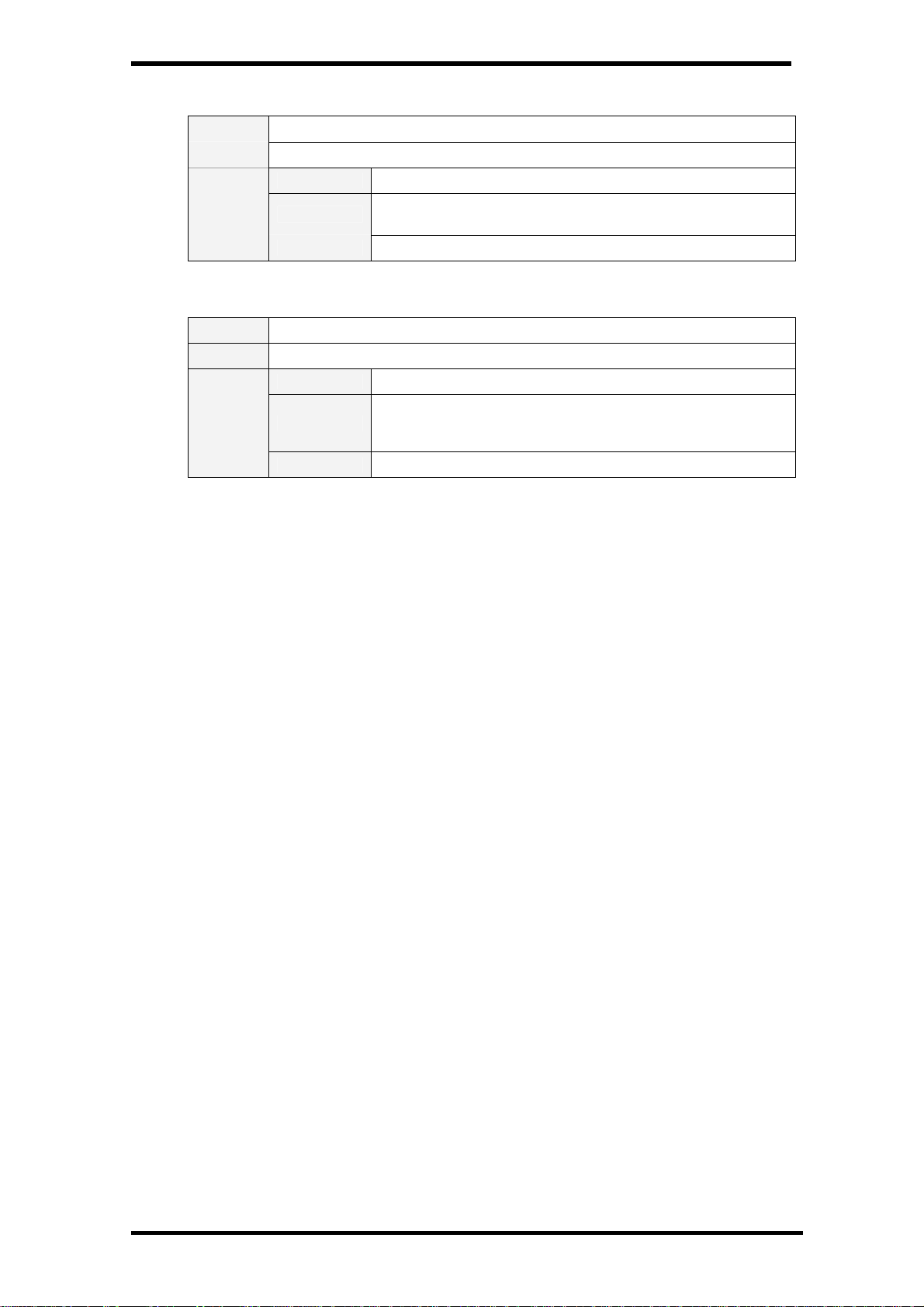
PLV-HD2000 Expand Serial Command Functional Specifications
9.9.9. CR_FANSPEED Command
Command “CR_FANSPEED” [CR]
Details Get currently selected Fan Control Speed
Acceptable “000_%1” [CR]
Response
%1
Unacceptable “Error Code” [CR]
“MAX” -------------------------- Fan Control Speed is set to Max
“NOR” -------------------------- Fan Control Speed is set to Normal
9.9.10. CR_KEYDIS Command
Command “CR_KEYDIS” [CR]
Details Get limitation status of RC/KEY use (valid or invalid)
Acceptable “000_%1” [CR]
Response
%1
Unacceptable “Error Code” [CR]
“NONE” -------------- Both RC & KEY are valid
“RC” ------------------- RC is invalid
“KEY” ----------------- KEY is invalid
50/56
Page 51
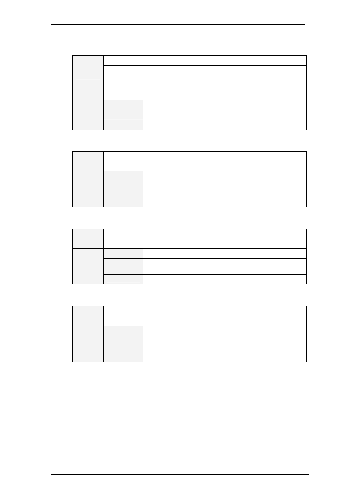
PLV-HD2000 Expand Serial Command Functional Specifications
9.10. Other Status Read Command
9.10.1. CR_PRESSURE Command
Command “CR_PRESSURE” [CR]
Get value from Air Pressure sensor
Following is the formula to work out Air Pressure from the given value (“Vn”
Details
Response
represents the value):
Air Pressure (hPa) = (5*Vn / 1024 – 0.204) / 0.00459 + 150
The accuracy of this value is +/-2%
Acceptable “000_%1” [CR]
%1 “0000” – “1023”
Unacceptable “Error Code” [CR]
9.10.2. CR_SIGNAL Command
Command “CR_SIGNAL” [CR]
Details Get status if there is any signal or not
Acceptable “000_%1” [CR]
Response
%1
Unacceptable “Error Code” [CR]
“ON” ------------------------ There is signal
“OFF” ---------------------- There is no signal
9.10.3. CR_VMUTE Command
Command “CR_VMUTE” [CR]
Details Get setting status of No Show
Acceptable “000_%1” [CR]
Response
%1
Unacceptable “Error Code” [CR]
9.10.4. CR_FREEZE Command
Command “CR_FREEZE” [CR]
Details Get setting status of Freeze
Acceptable “000_%1” [CR]
Response
%1
Unacceptable “Error Code” [CR]
“ON” ---------------------------- No Show is set to ON.
“OFF” -------------------------- No Show is set to OFF.
“ON” ---------------------------- Freeze is set to ON.
“OFF” --------------------------- Freeze is set to OFF.
51/56
Page 52

PLV-HD2000 Expand Serial Command Functional Specifications
9.10.5. CR_INFPFAIL Command
Command “CR_INFPFAIL” [CR]
Get the power failure status (Normal/Fail) at each check point.
Data consists of HEX values with 48 bits. Power Failure checkpoints are 16
points in Main Unit, 8 in Sub Power Unit, 1 in Current Sensor, and 4 in Fan Sensor.
For Main Unit and Sub Power Unit, each bit corresponds to their check points and
Details
indicates the status of “Normal/Abnormal” according to “HI/LO” logic.
Normal ------ HI (1) Power Failure ------ LO (0)
For Current sensor, the status of “Normal/Abnormal” is represented by whole 8bits
of “HI/LO”.
Normal ------ ALL HI (FF) Power Failure ------ ALL LO (00)
Acceptable “000_%1” [CR]
“ ************ ”
Represents hexadecimal digit with 48 bits as a 12-digit string.
47-32 Bits (16Bits) indicates the status of Main Unit No.1-16
31-24 Bits (8Bits) indicates the status of Sub Power Unit No.1-8
23- 16 Bits (8Bits) indicates the Current sensor status
15 - 0 Bits (16Bits) indicates the Fan sensor status
e.g.
“000000000000” ------ power is failed at all checkpoints.
“000100000000” ------ Main Unit No.1 is normal, others are failed
Response
%1
Unacceptable “Error Code” [CR]
“000200000000” ------ Main Unit No.2 is normal, others are failed
“000300000000” ------ Main Unit No.1-2 are normal, others failed
“FFFE00000000” ----- Main Unit No.2-16 are normal, others failed
“FFFF00000000” ----- Main Unit No.1-16 are all normal, others
failed
“000001000000” ----- Sub Power Unit No.1 is normal, others
failed
“0000FF0000” --- Sub Power Unit No.1-8 are normal, others failed
“FFFFFF00FF” ------ Main Unit, Sub Power Unit, and Fan sensor
are all normal, Current sensor is failed
“000000FF0000” -------- Current sensor is normal, others failed
“FFFFFFFFFFFF” ------ All power is normal
52/56
Page 53

PLV-HD2000 Expand Serial Command Functional Specifications
9.10.6. CR_TEMPWARN Command
Command “CR_TEMPWARN” [CR]
Get the information about the temperature inside the projector (close to/in the
abnormal status, in the safe temerature level or sensor not detect abnormal
Details
Response
temperature).
It is possible to get the information about more than one sensors all at once if it is
applicable.
Acceptable “000_%1” [CR]
“*_*”
Sensor 1 data comes first, and then one space, after that sensor
2 data is followed.
Each data is as below:
“W”--- in or close to the abnormal temp. (Warning Temp.)
“S”--- in the safe level of temp (Safe Temp.)
“N”--- the given sensor does not detect abnormal status.
%1
Unacceptable “Error Code” [CR]
e.g. “S_W” [CR] indicates that the temperature detected at
Sensor 1 is in the safe level while Sensor 2 in the abnormal
temperature.
Note) For some models, when the difference between the
temperatures in Sensor 1 and 2 is over the given threshold, it may
be determined as abnormal temperature. In this case, the
second value in the response indicates the temperature
abnormality of the difference between these sensors.
9.10.7. CR_TEMPFAIL Command
Command “CR_TEMPFAIL” [CR]
Get the temperature inside a projector when abnormal temperature status occurs.
Details
Response
It is possible to get the temperatures for more than one sensors all at once if it is
applicable.
Acceptable “000_%1” [CR]
%1
Unacceptable “Error Code” [CR]
e.g. “_31.5F” [CR]
“_” indicates a space. When the temperature goes under 0, the
first character is “-“, like “-05.5F” [CR].
With more than one temperature sensors installed, projector
returns the response for each sensor in a row.
e.g. “_31.5F_ 35 2S” [CR]
The first data indicates sensor 1 data, then one space, and
sensor 2 data is followed.
Last character in each data indicates the sensor’s status.
In the abnormal temperature ---------------------- ”F”
In the sefe level of temperature -------------------- ”S”
Not related with the abnormal temperature ------ ”N”
The above second example indicates that the temperature
detected by sensor 1 is 31.5 which means in the abnormal
temperature, and at sensor 2 is 32.5 degrees which is in the safe
temperature.
When the abnormal temperature status does not occur, the data
will be “_00.0S”.
When the projector is reset, “_00.0S” is set. Every time abnormal
temperature status is detected, it renews the data and returns it.
It only returns the renewed data of the latest abnormal
temperature and the previous data is cleeared.
53/56
Page 54

PLV-HD2000 Expand Serial Command Functional Specifications
10. Command with Address Specification
10.1. Overview
- Commands with address are used to remote control more than one projectors through RS-232C
by a computer.
- The command with address is defined as a single command per line that starts with “A” and
ends with carriage return (0x0D).
- When a projector receives carriage return (0x0D), it starts decoding.
- The address such as “A001” is prefixed to the Basic Serial Command or Expand Serial
Command already mentioned.
e.g.) Functional Execution Command: “A001C05” [CR]
e.g.) Status Read Command: “A001CR0” [CR]
- Projector has the function to set up its own address in Service mode.
・ Initial setting value is “No.001”
・ Available range of the value is “001” to “999”
- It clears the received buffer in the following cases.
・ When receiving LF (0x0A) or EOF (0x1A)
・ When it takes more than one second to receive a single command.
(when it takes more than one second until receiving carriage return after the reception of the
first data.)
54/56
Page 55

PLV-HD2000 Expand Serial Command Functional Specifications
10.2. Functional Execution Command with address
10.2.1.
Format
1) PC issues a command in the format below:
“A” Address “C” Command [CR]
or
“A” Address “CF_” Command “_” Parameter [CR]
Address: 3-digit number (”001” – “999”)
Commands with “FFF” as the address are valid to all projectors.
Command: string (Refer to Basic and Expand Serial Command)
2) The only projector with the appropriate address decodes the received command, and
when it gets ready to receive the next command, it returns the response.
[ACK] [CR]: When receiving Functional Execution Command (0x06, 0x0D)
“ ? “ [CR]: When the received data cannot be decoded
However, when the address is “FFF”, it executes the function but does not return the
response.
10.2.2.
When the command pipelining is needed
When it needs command pipelining, the operation is the same as the remote control as
below:
1) Sending system issues command every 100ms
2) When receiving the applicable command, it executes the function for 120ms
continuously.
3) When receiving the same command within 120ms in a row, the function is repeatedly
executed for another 120ms from the moment of the second command reception.
4) When there is no command after 120ms, the execution is stopped.
5) When receiving other command within 120ms, the execution is stopped.
55/56
Page 56

PLV-HD2000 Expand Serial Command Functional Specifications
10.3. Status Read Command with Address
10.3.1.
Format
1) PC issues a command in format as below:
“A” Address “CR” Command [CR]
or
“A” Address “CR_” Command [CR]
Address: 3-digit number (“001” – “999”)
Command: string (Refer to Basic and Expand Serial Command)
2) The only projector with appropriate address decodes the received commands and
returns the character line as the required data.
Required Data [CR]
Required Data: string (Refer to Basic Status Read Command)
3) When the received data cannot be decoded, it returns “ ? “ [CR]
56/56
 Loading...