

Sanyo PLV-HD10,PLV-HD100 Service Manual
FILE NO.
SERVICE MANUAL
REFERENCE NO. SM 5110515-00
PRODUCT CODE :
PLV-HD10 M4MA 1 122 165 00
PLV-HD10 P4MA 1 122 166 00
PLV-HD10 P4MC 1 122 166 02
PLV-HD100 M4MAV 1 122 165 40
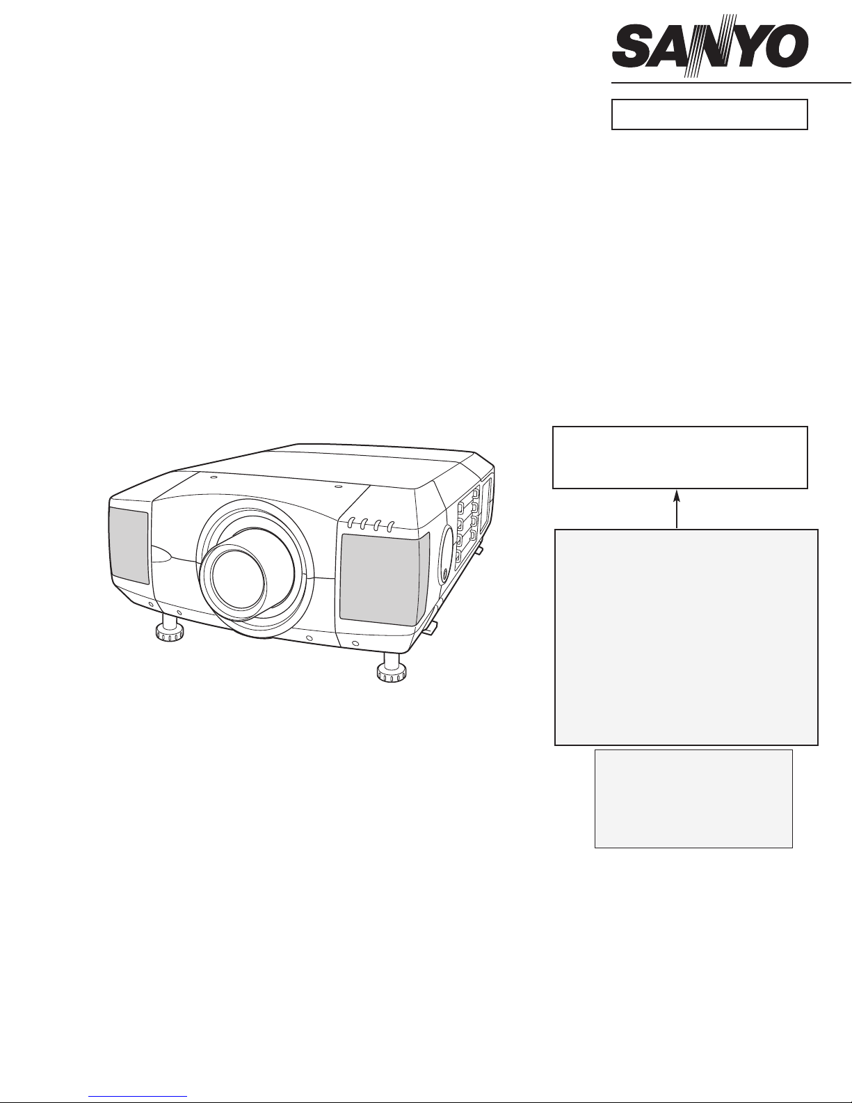
Multimedia Projector
Give complete “CHASSIS NO." for
parts order or servicing, it is shown on
the rating sheet on the cabinet of the
Projector.
Chassis No. M4M-HD1000
M4M-HD10000
NOTE: Match the Chassis No. on the rating
sheet on the cabinet with the Chassis
No. in the Service Manual.
If the Original Version Service
Manual Chassis No. does not
match the unites, additional Service
Literature is required. You must refer
to “Notices” to the Original Service
Manual prior to servicing the unit.
MODEL NO. PLV-HD10
PLV-HD100
(Projection lens is optional.)

- 2 -
CONTENTS
■ Safety Instructions..................................................................................................3
■ Specifications .........................................................................................................5
■ Protections .............................................................................................................6
■ Fuse for circuit protection .............................................................................6
■ Electric shock protection(Interlock switch) ................................................. 6
■ Overheating protection ................................................................................ 7
■ Indicators................................................................................................................8
■ Lamp replacement................................................................................................10
■ Mechanical disassemblies....................................................................................14
■ Optical unit disassemblies....................................................................................38
■ Optical parts location and direction ............................................................49
■ Maintenance.........................................................................................................51
■ Air filter care and cleaning..........................................................................52
■ Optical parts care and cleaning..................................................................53
■ Power supply lines ...............................................................................................54
■ Troubleshooting....................................................................................................55
■ No power ....................................................................................................55
■ No picture ...................................................................................................58
■ No sound ....................................................................................................63
■ Power lens system abnormality..................................................................64
■ Lamp abnormality...................................................................................... 65
■ Temperature abnormality ...........................................................................66
■ CPU & Data reset.......................................................................................68
■ Waveforms ...........................................................................................................69
■ Electrical Adjustments ..........................................................................................70
■ Service adjustment menu operation...........................................................70
■ Special menu..............................................................................................71
■ Service mode adjustment menu.................................................................72
■ Circuit Adjustments ....................................................................................74
■ Service Adjustment Data table(Factory Set Data List) ...............................78
■ Optical components adjustment ...........................................................................84
■ Control Port Functions..........................................................................................95
■ IC Block Diagrams..............................................................................................103
■ Parts list..............................................................................................................109
■ Readjustments after parts replacement ...................................................109
■ Mechanical and Optical parts list..............................................................113
■ Electrical parts list ....................................................................................124
■ Differences list..........................................................................................153
■ Schematic diagrams....................................................................................S1~S12
■ Block diagrams ....................................................................................................B1
■ PWB parts location diagrams ........................................................................P1~P5
- 3 -
WARNING:
The chassis of this projector is isolated (COLD) from AC line by using
the converter transformer. Primary side of the converter and lamp power
supply unit circuit is connected to the AC line and it is hot, which hot cir-
cuit is identified with the line ( ) in the schematic diagram. For con-
tinued product safety and protection of personnel injury, servicing
should be made with qualified personnel.
The following precautions must be observed.
Caution "HOT CIRCUIT"
Lamp Unit
Lamp ballast Unit
Power supply Unit
P.F.C. unit
SAFETY PRECAUTIONS
1: An isolation transformer should be connected in the power line between the projector and the AC line
before any service is performed on the projector.
2: Comply with all caution and safety-related notes provided on the cabinet back, cabinet bottom, inside the
cabinet or on the chassis.
3: When replacing a chassis in the cabinet, always be certain that all the protective devices are installed
properly, such as, control knobs, adjustment covers or shields, barriers, etc.
DO NOT OPERATE THIS PROJECTOR WITHOUT THE PROTECTIVE SHIELD IN POSITION AND PROP-
ERLY SECURED.
4: Before replacing the cabinet cover, thoroughly inspect the inside of the cabinet to see that no stray parts
or tools have been left inside.
Before returning any projector to the customer, the service personnel must be sure it is completely safe to
operate without danger of electric shock.
Safety Instructions
PRODUCT SAFETY NOTICE
Product safety should be considered when a component replacement is made in any area of the projector.
Components indicated by mark in the parts list and the schematic diagram designate components in which
safety can be of special significance. It is, therefore, particularly recommended that the replacement of the
parts must be made by exactly the same parts.
Caution:
The parts and screws should be placed exactly the same position as the original otherwise it may cause lose of
performance and product safety.
The wiring method of the leads should be returned exactly the same state as the original otherwise it may cause
lose of performance and product safety.
- 4 -
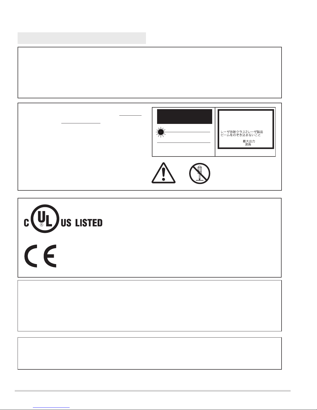
DO NOT ATTEMPT TO SERVICING THE REMOTE
CONTROL UNIT
.
Laser Beam may be leaked out when in disassemble
the Unit. As the Laser Beam used in this Remote
control unit is harmful to the eyes.
SERVICE PERSONNEL WARNING
Eye damage may result from directly viewing the light produced by the Lamp used in this equipment. Always
turn off Lamp before opening cover. The Ultraviolet radiation eye protection is required during this servicing.
Never turn the power on without the lamp to avoid electric-shock or damage of the devices since the stabilizer
generates high voltages at its starts.
Since the lamp is very high temperature during units operation. Replacement of the lamp should be done at
least 45 minutes after the power has been turned off, to allow the lamp cool-off.
CAUTION
RISK OF EXPLOSION IF BATTERY IS REPLACED BY AN INCORRECT TYPE.
DISPOSE OF USED BATTERIES ACCORDING TO THE INSTRUCTIONS.
CAUTION
Not for use in a computer room as defined in the Standard for the Protection of Electronic Computer/Data
Processing Equipment, ANSI/NFPA 75.
Ne puet être utillisé dans une salle d’ordinateurs telle que définie dans la norme ANSI/NFPA 75 Standard for
Protection of Electronic Computer/Data Processing Equipment
This symbol on the rating sheet means the product is Listed by
Underwriters Laboratories Inc. It is designed and manufactured to meet
rigid U.L. safety standards against risk of fire, casualty and hazards.
The CE Mark is a Directive conformity mark of the European Community
(EC).
CAUTION
LASER RADIATION
DO NOT STARE INTO BEAM
MAX. OUTPUT: 1mW
WAVE LENGTH: 650±20nm
II LASER PRODUCT
CLASS
This product is complied with 21 CFR
part 1040.10
LASER RADIATION
DO NOT STARE INTO BEAM
CLASS 2 LASER PRODUCT
LASER-STRAHLING
NICHT IN DEN STRAHL BLICKEN
LASER KLASSE 2
IEC60825-1, Am. 1 1997
MAX OUTPUT ( ) : 1 mW
WAVE LENGTH ( ) : 650±20nm
- 5 -
Owner’s Manual
AC Power Cord
Wireless/Wired Remote Control Transmitter and Batteries
Remote Control Cable
DVI-VGA Cable and DVI Cable
MAC/VGA Adapter
SerialCable (Control port)
6 Types Light-Block Sheet (For option lens)
Lens Mounting Parts
Protective Dust Cover
Accessories
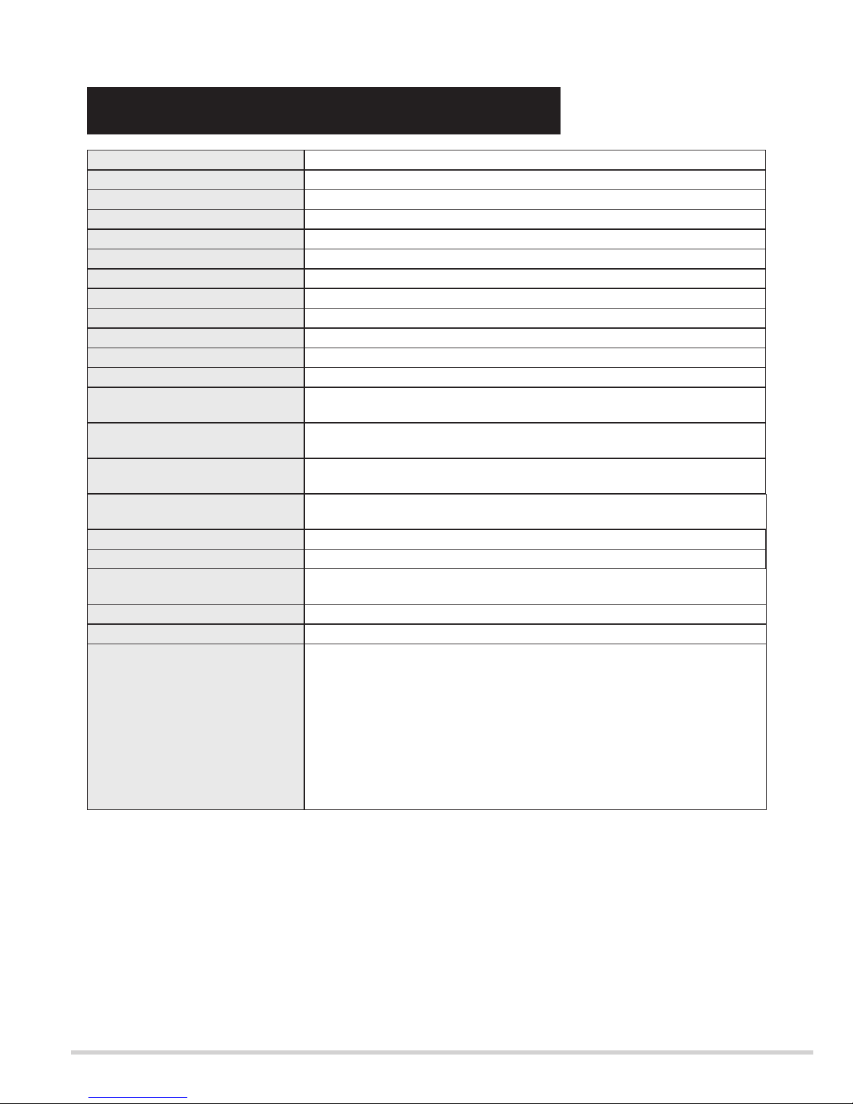
1.65" TFT Active Matrix type, 3 panels
Multi-media Projector
83.9 lbs (38 kg)
22.9" x 10" x 30.9" (581 mm x 252 mm x 783 mm)
1,920 x 1,080 dots
6,220,800(1,920 x 1,080 x 3 panels)
PAL, SECAM, NTSC, NTSC4.43, PAL-M and PAL-N
Up, Down, Left and Right
1100 TV lines (HDTV)
INT. SP. Stereo (R and L), 3 watt RMS (T.H.D. 10%)
41˚F ~ 95˚F (5˚C ~ 35˚C)
14 ˚F ~ 140 ˚F (-10 ˚C ~ 60 ˚C)
Projector Type
Net Weight
Dimensions
(W x H x D)
Panel Resolution
Number of Pixels
Color System
Scanning Frequency
Horizontal Resolution
Built-in Speakers
Operating Temperature
Storage Temperature
LCD Panel System
250 watt type x 4
Projection Lamp
0˚ to 5.7˚
Feet Adjustment
480i, 480p, 575i, 575p, 720p, 1035i, 1080i-50 and 1080i-60
High Definition TV Signal
AC 120 V (12 A Max. Ampere), 50 / 60 Hz
(The U.S.A and Canada)
AC 200 ~ 240 V (7.5 A Max. Ampere), 50 / 60 Hz
(Continental Europe and The U.K.)
Voltage and
Power Consumption
H-sync. 15 ~ 120 KHz, V-sync. 50 ~ 120 Hz
Motorized Lens Shift
BNC Type x 3 (SDI Input 1, SDI Input 2 and SDI Output)
Input 1 Jacks
BNC Type x 5 (R/Pr, G/Y, B/Pb, H/HV and V), RCA Type (Audio R and L)
and DIN 8-pin (Control port)
Input 2 Jacks
DVI-I Terminal (Digital/Analog), RCA Type (Audio R and L)
and DIN 8-pin (Control port)
Input 3 Jacks
Serial port in (DB 9), Serial port out (DB 9), USB port,
Audio Monitor out (RCA Type R and L) and Wired Remote Jack
Other Jacks
● Specifications are subject to change without notice.
● LCD panels are manufactured to the highest possible standards. At least 99.999% of the pixels are
effective, however a tiny fraction of the pixels (0.001% or less) may be ineffective by the characteristics of
the LCD panels.
TECHNICAL SPECIFICATIONS
● The specifications are subject to change without notice.
- 6 -
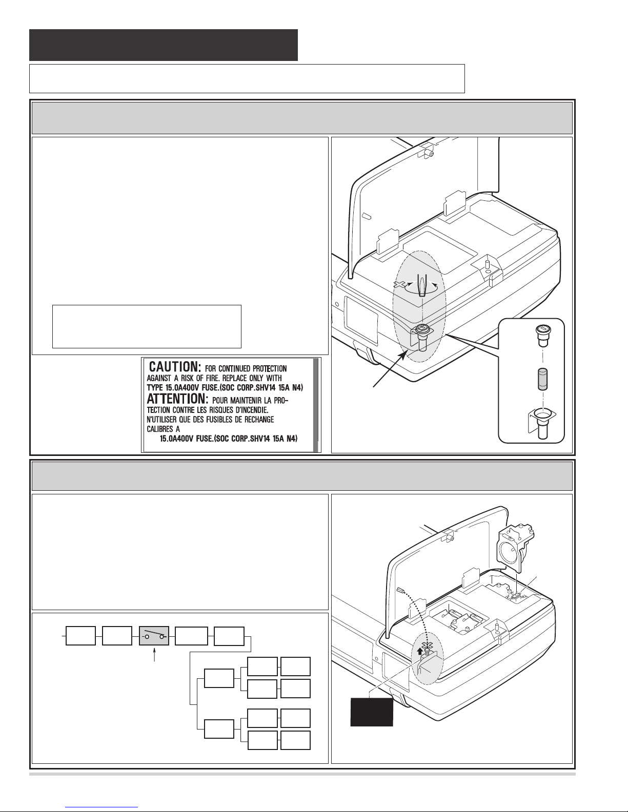
This projector is equipped with the following protections to operate in safety.
Protections
❏ Fuse for circuit protection
The fuse is located in the rear inside a projector. (Refer to figure.) When
either the LAMP indicator or the READY indicator is not illuminated,
fuse may be opened. Check the fuse as following steps.
1. Remove the Cabinet-top following to “Mechanical Disassemblies”.
2. Remove the fuse from fuse holder. (Refer to right figure.)
Turns the fuse holder cover with the slot screw driver.
Remove the fuse and the fuse holder cover upward.
3. Check the resistance of fuse using a tester.
To install the fuse, take reversed step in the above.
It should be used the specified fuse as follows;
❏ Protection equipment for users Electric shock protection. (Interlock switch)
The label of the right
figure sticks near the
Fuse.
Cover
Fuse
Holder
Fuse
F901
Fuse Part No.: 423 028 4209
TYPE 15.0A400V FUSE
SOC CORP. SHV14 15A N4
■ The Lamp circuit (the lamp and the electrode of the lamp socket) of this
projector is not insulated from AC line, and it is "HOT." Therefore,
when replacing lamp assembly, an electric shock may be received.
However, the interlock switch (SW902) is designed so that it may pro-
tect from the accident.
■ This switch (SW902) insulates a lamp circuit from AC line, when
cover-top is opened. (The lamp circuit changes to "COLD.")
SW902
AC INPUT
Fuse
F901
Main sw
SW901
Interlock SW
SW902
Current
Sensor
P.F .C.
1-2
P.F .C.
3-4
Ass'y
Power
Lamp
ballast_1
Lamp
ballast_2
Lamp
ballast_3
Lamp
ballast_4
Lamp 1
Lamp 2
Lamp 3
Lamp 4
Interlock
switch
Cover top
Lamp socket
- 7 -
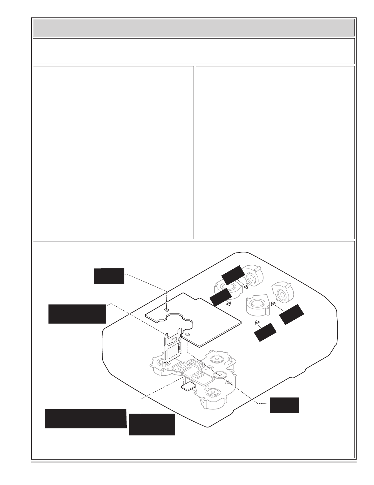
❏ Overheating Protection -- The temperature monitor system --
----- The temperature monitor -1: -----
■ To control the driving power of the cooling fans.
The CPU checks the temperature and atmospheric pres-
sure inside a projector. It checks a temperature using
temperature sensor-IC5801and it checks an atmospheric
pressure using pressure sensor-IC4849.
The CPU controls the driving power of the cooling fans
so the temperature inside the projector is maintained to
normal temperature.
■ To shut down the projector.
The CPU checks temperature of Blue polarization glass
(PTH901) and inhalation air(IC5801). If each part tem-
perature reaches to abnormal temperature, the CPU will
turn off a projector, and will blink WARNING TEMP.
indicator at intervals of 0.6 seconds. Cooling fans operate
until temperature returns to normal. Indicator will stop
blink, if temperature returns to normal.
The temperature monitor system is provided to prevents damage of optical components (the LCD panel and polarization film
etc.) inside a projector from overheat. Two protection systems are provided.
Each system operation as follows ;
----- The temperature monitor -2 : -----
(Temperature check of lamps. )
Temperature switches (SW 903~906) are arranged near
the four lamps. Temperature switches will operate, if
temperature reaches 100 degrees.
SW (903~906) ----- It operates at 100 degrees.
(Lamp-1~4)
When temperature switches have operated, lamp ballast
units will be shut down, then a projector will be turned
off.
Note. The CPU does not check operation of temperature
switches. Therefore, when temperature switches have
operated and a projector has shut down, WARNING
TEMP. indicator does not blink.
PRESSURE
SENSOR
IC4849
PTH901
Temp. Sensor
(Blue polarization glass)
Front side
Temperature sensors
location
Blue polarizer unit
IC5801
Temp. Sensor
nhalation air
(I
A-Side
)
B-Side
Main
SW906
100*C
For
SW905
100*C
For
Lamp3
Tem perature s
are arranged to Bottom of the optical unit.
Lamp4
For
Lamp2
SW904
100*C
For
Lamp1
SW903
100*C
witches (SW903/904/905/906)
Tem p.
SENSOR
IC1519
- 8 -
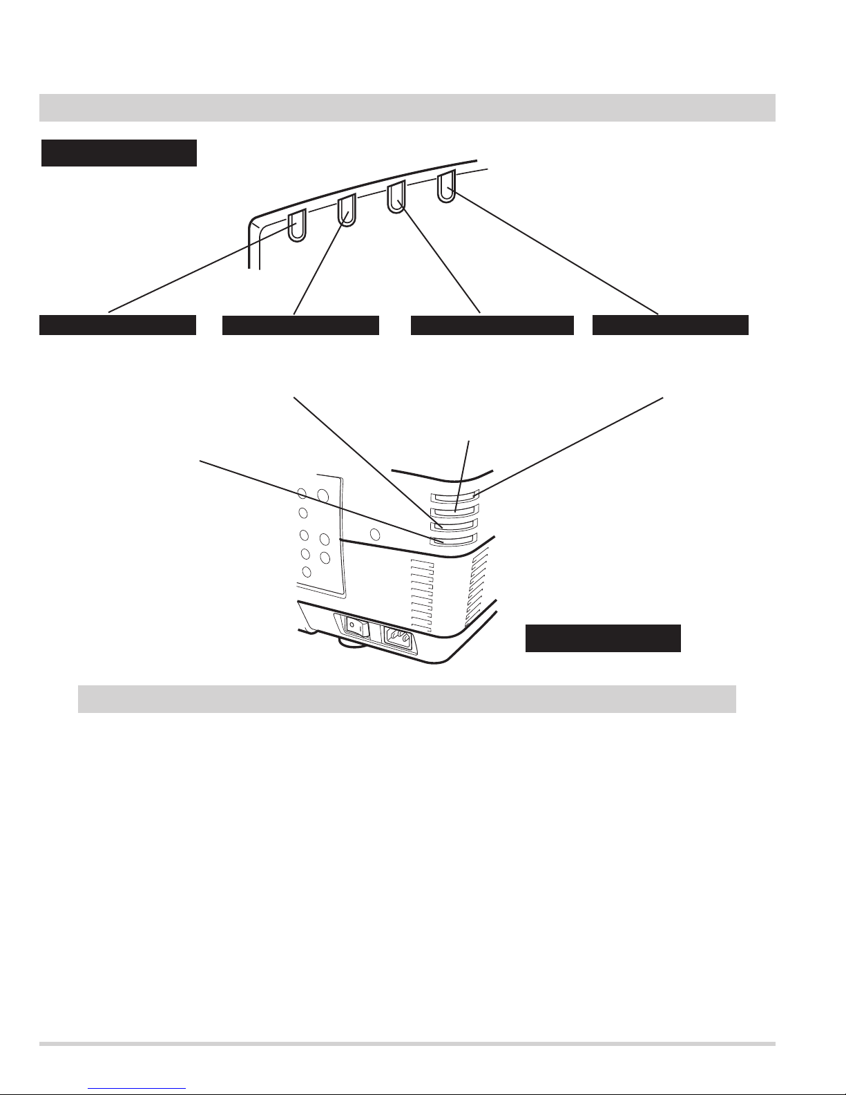
READY indicator
LAMP indicator
LAMP REPLACE indicator
This indicator lights green
when a projector is ready to
be turned on. And it flashes
green in Power Management
mode or internal projector
temperature is to high.
This indicator is dim when a
projector is turned on. And
bright when a projector is in
stand-by mode.
INDICATORS
WARNING TEMP. indicator
This indicator flashes red
when internal projector
temperature is too high.
WARNING
TEMP.
READY
LAMP
REPLACE
LAMP
FRONT INDICATORS
REAR INDICATORS
This LAMP REPLACE
indicator lights yellow when
any of Projection Lamps is
nearing its end, and flashes
when any of them becomes
out. Check which lamp
needs to be replaced on
Lamp Status Display.
When both of the Warning Temp. and Ready indicators are flashing:
When the projector detects an internal problem, it will shut down automatically and both of the Warning temp. and
Ready Indicators starts flashing. In this condition, the projector cannot be turned on even if you press the On/Off
button on the remote control unit or on the side control. If this case happenes, disconnect and reconnect the AC
power cord, and then turn on the projector again to check its operation.
Check the following possible causes and wait until stopping the WARNING TEMP. indicator flashing.
Possible causes
- Air filter is clogged with dust particles. Remove dust from the air filter by following instruction in the
"Air filter care and cleaning".
- Ventilation slots of the projector are blocked. In such an event, reposition the projector so that ventilation
slots are not obstructed.
- Check if projector is used at higher temperature place(Normal operate is 5 to 5°C or 41 to 95°F)
WARNING
LAMP
REPLACE
TEMP.
READY
LAMP
- 9 -
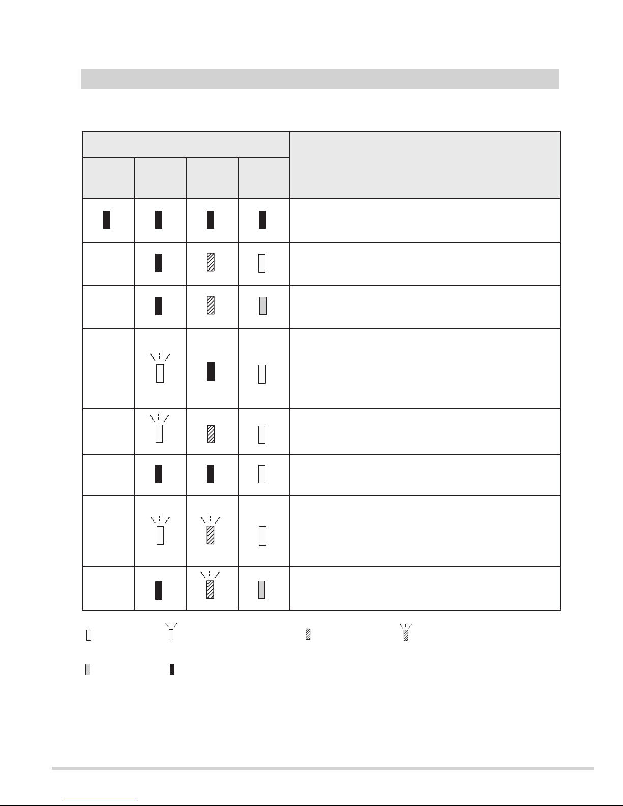
INDICATORS AND PROJECTOR CONDITION
Check the Indicators for projector condition.
• • • on : red
• • • dim
• • • off
• • • flashing : red
When the life of the projection lamp draws to an end, the LAMP REPLACE indicator lights yellow. When
this indicator lights yellow, replace the projection lamp with a new one promptly. Reset the Lamp Replace
Counter after replacement of the lamp.
The projector is OFF. (The MAIN switch OFF position or the
AC Power Cord is unplugged.)
The projector is READY to be turned on with the POWER ON-
OFF button.
The temperature inside the projector is abnormally high. The
projector cannot be turned on. When the projector is cooled
down enough and the temperature returns to normal, the
READY indicator lights green and the projector can be turned
on. (The WARNING TEMP. indicator keeps flashing.) Check
and clean the Air Filter.
The projector is being cooled down. It cannot be turned on until
the READY indicator lights green.
Projector Condition
The projector is operating normally.
The projector is cooled down enough and the temperature
returns to normal. When turning on the projector, the WARNING
TEMP. indicator stops flashing. Check and clean the Air Filter.
Indicators
READY
green
LAMP
red
The projector detects an abnormal condition and cannot be
turned on. Unplug the AC Power Cord and plug it again to turn
on the projector. If the projector is turned off again, disconnect
the AC Power Cord and contact the dealer or the service center
for service and checkup. Do not leave the projector on. It may
cause electric shock or a fire hazard.
The projector is in the Power management mode.
❈
❈
❈
❈
❈
❈
❈
WARNING
TEMP.
red
LAMP
REPLACE
yellow
• • • on : green • • • flashing : green
- 10 -
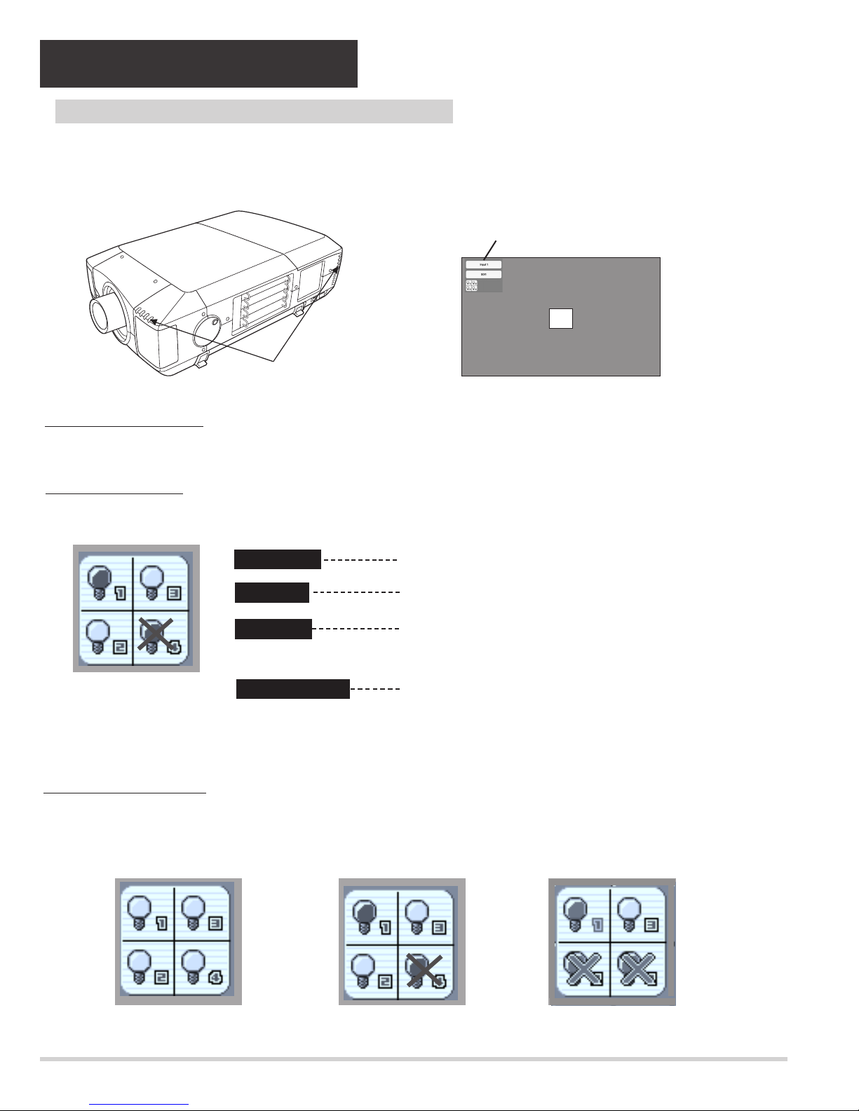
This Projector is equipped with 4 Projection Lamps to ensure brighter image and those lamps are controlled by Lamp
Management Function. Lamp Management Function detects status of all lamps and shows status on screen or on LAMP
REPLACE indicator. This function also automatically controls Lamp Mode when any of lamps is out for end of life or
malfunctions.
Projection Lamp lights normally.
Lamp Replace Indicator
This LAMP REPLACE indicator lights yellow when any of Projection Lamps is nearing its end, and flashes when any of them
becomes out. Check number of lamp on Lamp Status Display and replace lamp.
Yellow Lamp
Dim Lamp
X Mark on Lamp
Red Lamp
LAMP REPLACE
INDICATOR
Projection Lamp is turned off.
Projection Lamp is nearing its end. When image becomes
darker or color becomes unnatural, replace lamp. (LAMP
REPLACE indicator lights yellow.)
(LAMP REPLACE indicator flashes yellow.)
Projection lamp is defective or fails to be turned on. Restart
a projector on, and make sure lamp is on. If this mark still
appears, replace lamp corresponding with number marked
X.
LAMP STATUS
DISPLAY
Lamp Mode Changeover
Lamp Management Function automatically changes combination of lighting lamp (Lamp Mode) by detecting status of lamp.
When any of 4 lamps becomes out, Lamp Mode is changed over from 4 lamps to 2 lamps. And when any of 2 lamps are out,
a projector operates with 1 lamp. Lamp Mode can be switched to 4 lamps or 2 lamps manually.
4 LAMP MODE
2 LAMP MODE
(Example)
1 LAMP MODE
(Example)
Lamp Status Display
Lamp Status Display appears on screen when power switch is on or changed input position (input 1, input 2, Input 3 or input 4).
This shows status of each lamp as; ON, OFF, NEAR END, or OUT. Refer to following for each status.
30
INPUT AND LAMP STATUS
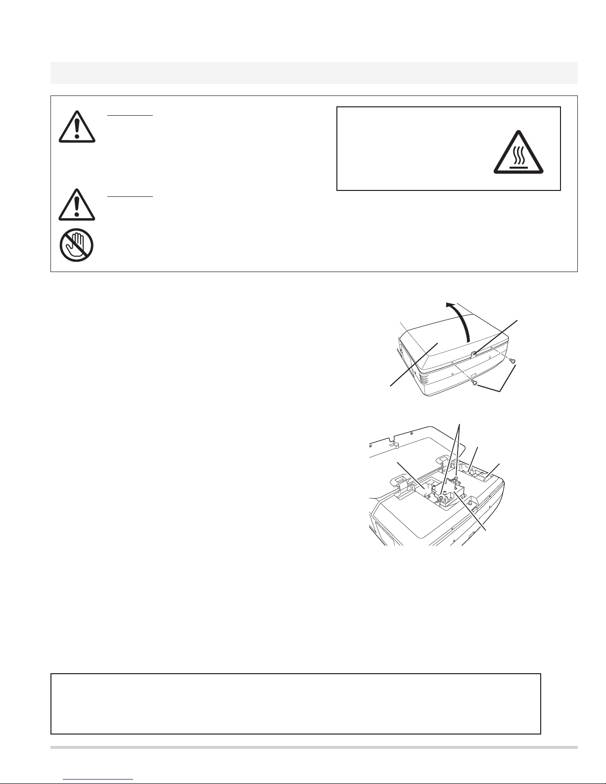
LAMP REPLACEMENT
Before Replacement
- 11 -
LAMP REPLACEMENT
CAUTION
Do not drop a lamp assembly or touch a glass
bulb! Glass can shatter and may cause injury.
CAUTION
For continued safety, replace with a lamp
assembly of same type.
Allow a projector to cool for at least 45 minutes
before you open Lamp Cover. Inside of a
projector can become very hot.
Check number of lamp to be replaced on Lamp Status
Display.
Remove two screws on Lamp Cover and press button to
open Lamp Cover. (See right figure.)
1
3
Loosen two screws and pull out Lamp Assembly to be
replaced by grasping handle.
4
Turn off a projector and disconnect AC Power Cord.
Allow a projector to cool down for at least 45 minutes.
2
Replace Lamp Assembly with a new one and tighten two
screws. Make sure Lamp is set properly.
6
Follow these steps to replace lamp assembly.
Replace Lamp Cover and tighten two screws.
5
7
8
Connect AC Power Cord to a projector and turn a
projector on.
Reset Lamp Replacement Counter. (Refer to section
"Lamp Counter Reset".)
NOTE : Do not reset LAMP REPLACEMENT COUNTER when
lamp is not replaced.
BUTTON
SCREWS
LAMP
COVER
Make sure which number of lamp needs to be
replaced on Lamp Status Display.
Figure shows case of replacing LAMP 2.
CAUTION : Do not operate a Projector while any of lamps removed.
It may result in malfunctions, fire hazard, or other accidents.
NOTES ON LAMP REPLACEMENT
To maintain quality of picture (better balance of color and brightness in entire screen), we recommend replacing all 4 lamps at a time.
CAUTION : High pressure lamp may explode if improperly handled.
Refer to lamp replacement instructions.
CAUTION
HIGH VOLTAGE
HOT
LAMP1
SCREWS
LAMP3
LAMP4
LAMP2
- 12 -
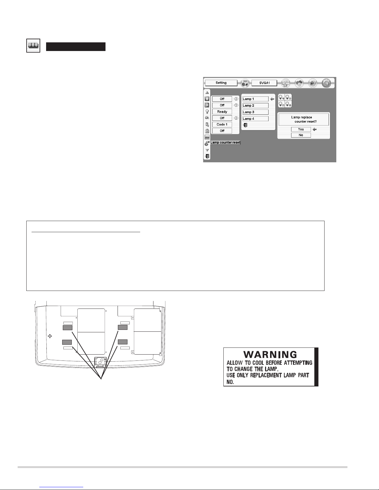
Lamp counter reset
Be sure to reset Lamp Counter when Lamp Assembly is replaced. When Lamp Replace Counter is reset, LAMP
REPLACE indicator stops lighting.
Turn projector on, press MENU button and ON-SCREEN
MENU will appear. Press POINT LEFT/RIGHT button(s) to
move a red frame pointer to SETTING Menu icon.
1
Press POINT DOWN button to move a red frame pointer to
“Lamp counter reset” and then press
SELECT button.
2
Do not reset Lamp Replace Counter except after Projection lamp is
replaced.
Another confirmation dialog box appears and select [Yes] to
reset Lamp Replace Counter.
4
Move arrow to replaced lamp number (Lamp 1, Lamp 2, Lamp 3
or Lamp 4) and then press
SELECT button. Message "Lamp
replace counter Reset?" is displayed. Move pointer to [Yes] and
then press SELECT button.
3
NOTE: Be sure to reset correct lamp number otherwise LAMP
REPLACE indicator continues lighting.
The label of the right figure sticks to here.
Lamp replacement caution label
ORDER REPLACEMENT LAMP
Replacement Lamp can be ordered through your dealer. When ordering a Projection Lamp, give the
following information to the dealer.
●
Model No. of your projector : PLV-HD10
● Replacement Lamp Type No. : POA-LMP72
(Service Parts No. 610 305 1130)
LAMP1
LAMP2
LAMP3
LAMP4
610 305 1130
1AA6P4S2207-E
- 13 -
CARRYING AND TRANSPORTING A PROJECTOR
● Do not drop or bump a projector, otherwise damages or malfunctions may result.
● When carrying a projector, use a suitable carrying case.
● Do not transport a projector by using a courier or transport service in an unsuitable transport
case. This may cause damage to a projector. To transport a projector through a courier or
transport service, consult your dealer and best case should be applied.
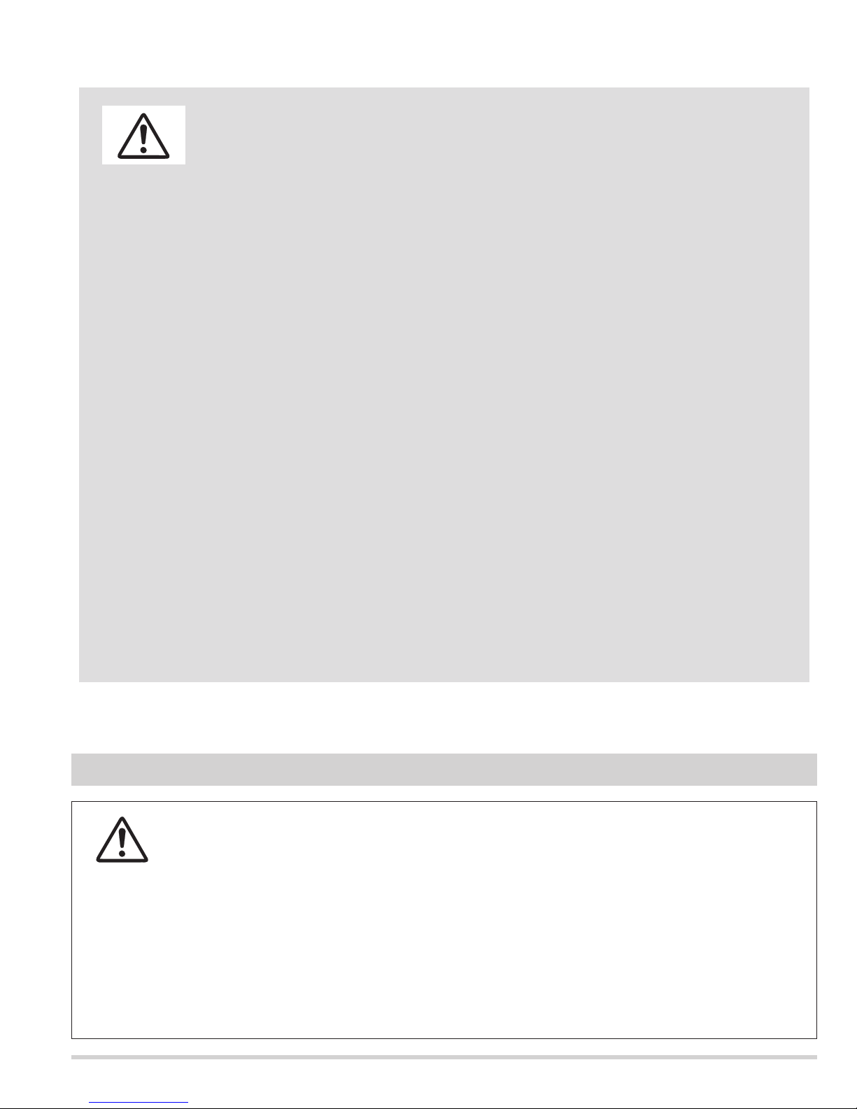
CAUTION IN CARRYING OR TRANSPORTING A PROJECTOR
This projector uses a high-pressure lamp which must be handled carefully and properly. Improper handling may
result in accidents, injury, or create a fire hazard.
● Lamp lifetime may differ from lamp to lamp and according to the environment of use. There is no guarantee
of the same lifetime for each lamp. Some lamps may fail or terminate their lifetime in a shorter period of time
than other similar lamps.
● If the projector indicates that the lamp should be replaced, i.e., if the LAMP REPLACE INDICATOR lights up,
replace the lamp with a new one IMMEDIATELY after the projector has cooled down.
( Follow carefully the instructions in the LAMP REPLACEMENT section of owner's manual. ) Continuous use
of the lamp with the LAMP REPLACE INDICATOR lighted may increase the risk of lamp explosion.
● A Lamp may explode as a result of vibration, shock or degradation as a result of hours of use as its lifetime
draws to an end. Risk of explosion may differ according to the environment or conditions in which the
projector and lamp are being used.
IF A LAMP EXPLODES, THE FOLLOWING SAFETY PRECAUTIONS SHOULD BE TAKEN.
If a lamp explodes, disconnect the projector’s AC plug from the AC outlet immediately. Contact an authorized
service station for a checkup of the unit and replacement of the lamp. Additionally, check carefully to ensure
that there are no broken shards or pieces of glass around the projector or coming out from the cooling air
circulation holes. Any broken shards found should be cleaned up carefully. No one should check the inside of
the projector except those who are authorized trained technicians and who are familiar with projector service.
Inappropriate attempts to service the unit by anyone, especially those who are not appropriately trained to do so,
may result in an accident or injury caused by pieces of broken glass.
LAMP HANDLING PRECAUTIONS
- 14 -
Mechanical disassemblies
Disassemble should be made following procedures in numerical order.
Following steps show the basic procedures, therefore unnecessary step may be ignored.
Caution:
The parts and screws should be placed exactly the same position as the original otherwise it may cause lose of per-
formance and product safety.
The wiring method of the leads should be returned exactly the same state as the original otherwise it may cause lose
of performance and product safety.
Fig.1-1
Fig.1-2
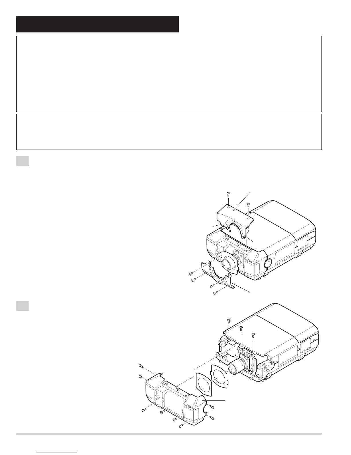
1-1
Cabinet-front-top unit and Cabinet-front-bottom unit removal.
1-2
Cabinet-front unit removal.
Note :Be careful not to damage Hook. The cabinet-front-top unit is being fixed with cabinet-front-bottom by hook.
1. Remove 2 screws-A.
Push part(a) and pull the Cabinet-front-top unit upward.
2. Remove 4 screws-B and remove the Cabinet-front-bottom unit.
(See Fig.1-1)
Refer to Lens replacement and installation manual.
1. Remove 11 screws and remove the Cabinet-front unit.
(See Fig.1-2)
Before Disassemblies :
Turn off a projector and disconnect the AC power cord.
When remove the lens shift unit, shift to the position from which the attachment screw of a lens shift unit and an opti-
cal base can be removed.
A
Hook
(a)
B
B
B
B
A
Cabinet front top
unit
A
(a)
Cabinet front bottom unit
A
A
A
A
Cabinet front unit
A
A
A
A
A
A
- 15 -
A
Fig.1-3
Fig.1-4
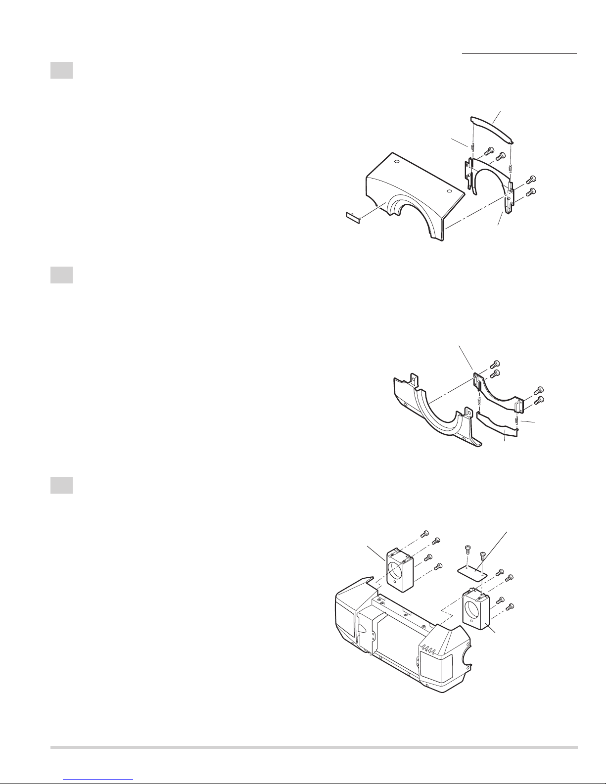
1-3
Cabinet front-top-unit disassemblies.
1. Remove 4 screws and remove the Mounting cover lens-A.
2. Remove 2 Spring coils and remove Cover lens-A.
3. The bent portion is stretched and remove the badge from
cabinet front top.
(See Fig.1-3)
1-4
Cabinet front-bottom-unit disassemblies.
1. Remove 4 screws and remove the Mounting Cover lens-B.
2. Remove 2 Spring coils and remove Cover lens-A.
(See Fig.1-4)
Mechanical disassemblies
1-5
Speaker units and Front LED Board removal.
1. Remove 4 screws-A and remove the Speaker unit-A.
2. Remove 4 screws-B and remove the Speaker unit-B.
3. Remove 2 screws-C and remove the Front LED Board.
(See Fig.1-5)
Fig.1-5
Cover lens-A
Spring coil-A
Cabinet front top
Mounting cover lens-
Badge
Mounting cover lens-B
Cabinet front bottom
Speaker unit-A
Spring
coil-B
Cover lens-A
A
A
C
A
A
Front LED Board
C
B
B
B
B
Speaker unit-B
Cabinet front
- 16 -
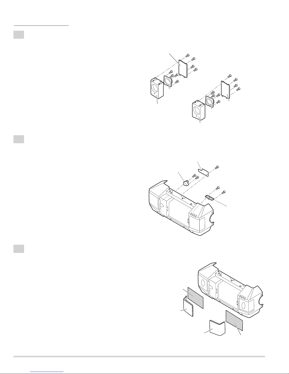
1-7
Decoration Inlays and R/C-1 Board removal.
1-6
Speaker units disassemblies.
1. Remove screw-A and remove the R/C-1 Board.
2. Remove 2 screws-B and remove the DEC Inlay R/C-F.
3. Remove 2 screws-C and remove the DEC Inlay-A.
(See Fig.1-7)
1-8
Speaker Grills and Nets removal.
1. The bent portion is stretched and remove the Grille SP-L,
remove the Grille SP-R from cabinet front.
2. Remove the Nets.
(See Fig.1-8)
Mark the Grills as they are removed from the Cabinet front so that
they may be reassembled in the same location from which they
were removed. Be careful of the attached direction of Grills.
1. Remove 4 screws-A and remove the Mounting SP-D.
2. Remove 4 screws-B and remove the Speaker-B.
3. Remove 4 screws-C and remove the Mounting SP-C.
2. Remove 4 screws-D and remove the Speaker-A.
(See Fig.1-6)
Fig.1-6
Fig.1-7
Fig.1-8
Mechanical disassemblies
Mounting SP-D
Speaker-B
Mounting SP-B
A
A
A
B
B
B
B
A
D
D
D
D
Speaker-A
C
C
C
C
Mounting SP-C
DEC Inlay R/C-F
Net
Mounting SP-A
R/C 1 Board
B
B
A
C
C
DEC Inlay A
Cabinet front
Grill SP-L
Grill SP-R
Net
- 17 -
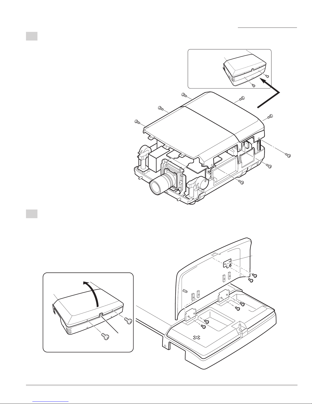
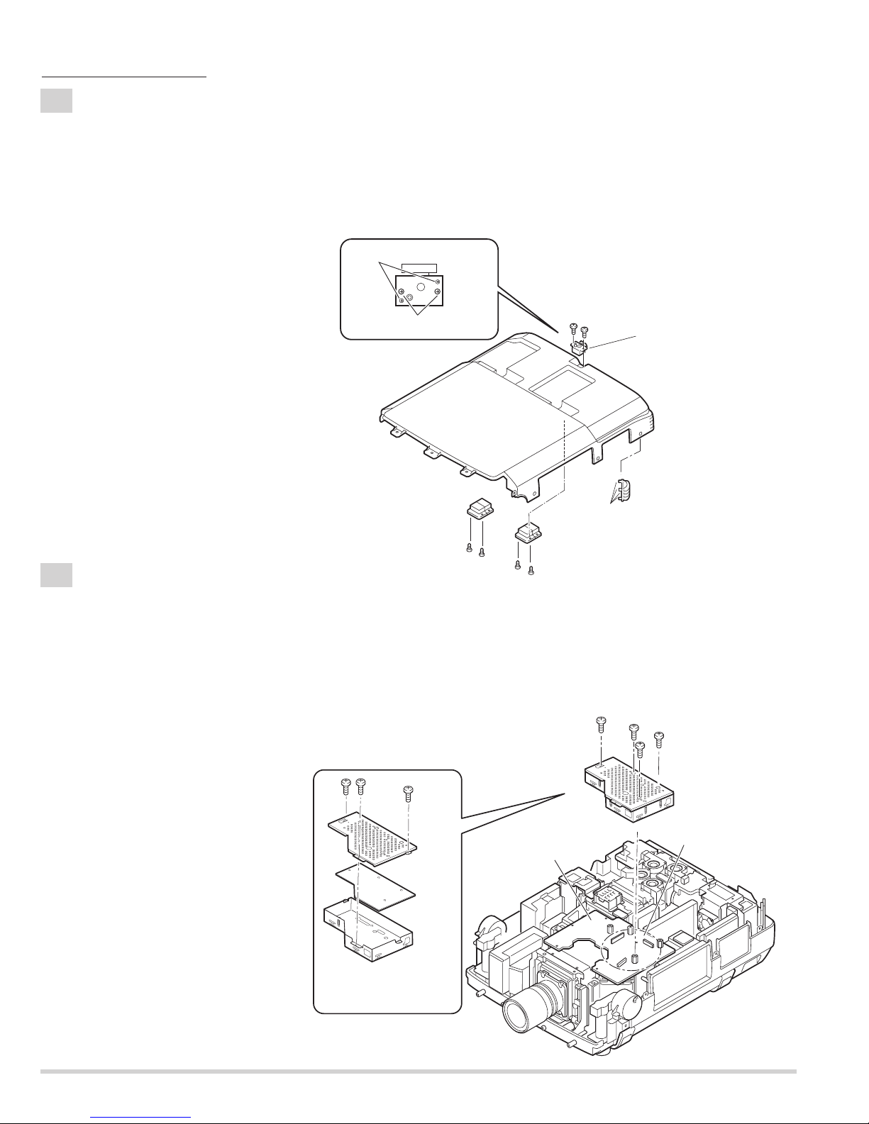
2-1
Cabinet-top unit removal.
1. Remove 8 screws and remove the Cabinet-top unit.
(See Fig.2-1)
2-2
Lamp cover and Push Latch-B removal.
1. Remove 2 screws-A and press button to open the Lamp cover.
2. Remove 4 screws-B and remove the Lamp cover.
3. Remove 2 screws-C and remove the Push Latch-B.
(See Fig.2-2, 2-2a)
Fig.2-1
Fig.2-1a
Fig.2-2
Fig.2-2a
Back View
Mechanical disassemblies
Cabinet top unit
Lamp cover
A
Press
Button
Push Latch-B
C
Lamp cover
Cabinet top
B
A
B
C
B
B
- 18 -
2-3
Decoration Inlay-B, Push Latch-A, and Hinges removal.
1. Remove 4 screws-A and remove the 2 Hinges.
2. Remove 2 screws-B and remove the push Latch-A.
3. Remove DEC Inlay-B. (Unhook the Cabinet top and take the DEC Inlay off inside.)
Push part(a) and pull the DEC Inlay inside.
(See Fig.2-3, 2-3a)
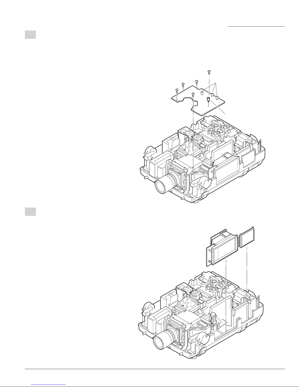
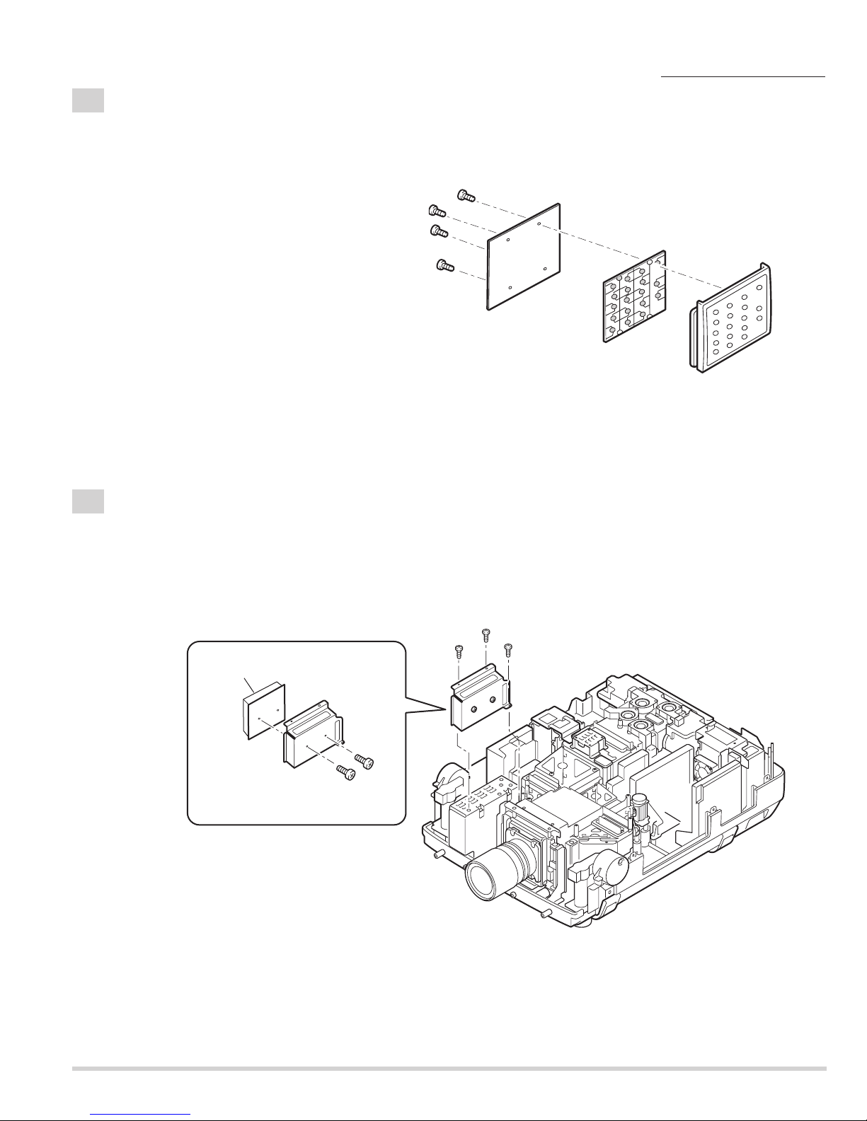
3-1
BGA Board removal.
Fig.2-3
Fig.2-3a
Fig.3-1
Fig.3-1a
Mechanical disassemblies
1. Remove 4 screws-A and remove the BGA unit.
Be careful not to damage connector, Main Board and BGA Board are connected.
2. Remove 3 screws-B and disassemble the BGA unit.
(See Fig.3-1,3-1a)
Do not remove
Remove the screws
Cabinet top
B
B
Push Latch-A
Hook
Hinge
Hinge
A
A
A
A
B
B
B
Main Board
Shield BGA-B
A
(a)
DEC Inlay-B
A
A
A
BGA unit
Be careful connectors
BGA Board
Shield BGA-A
- 19 -
3-2
Main Board removal.
Remove the connectors and the flexible cables of the LCD panels from the Main Board.
(Never touch the electrode of flexible cables.)
1. Remove 5 screws-A.
2. Remove spacer-A and remove the Main Board.
(Do not remove the Spacer-B.)
(See Fig.3-2)
4
-1
Control switch unit and Terminal slots unit removal.
1. Remove the Control switch unit upward.
2. Remove the Terminal slots unit upward.
(See Fig.4-1)
Fig.3-2
Fig.4-1
Mechanical disassemblies
A
MAIN Borad
A
A
A
A
Spacer-B
(Do not remove)
Spacer-A
Terminal slo
Unit
Control-Switch
Unit
ts
- 20 -
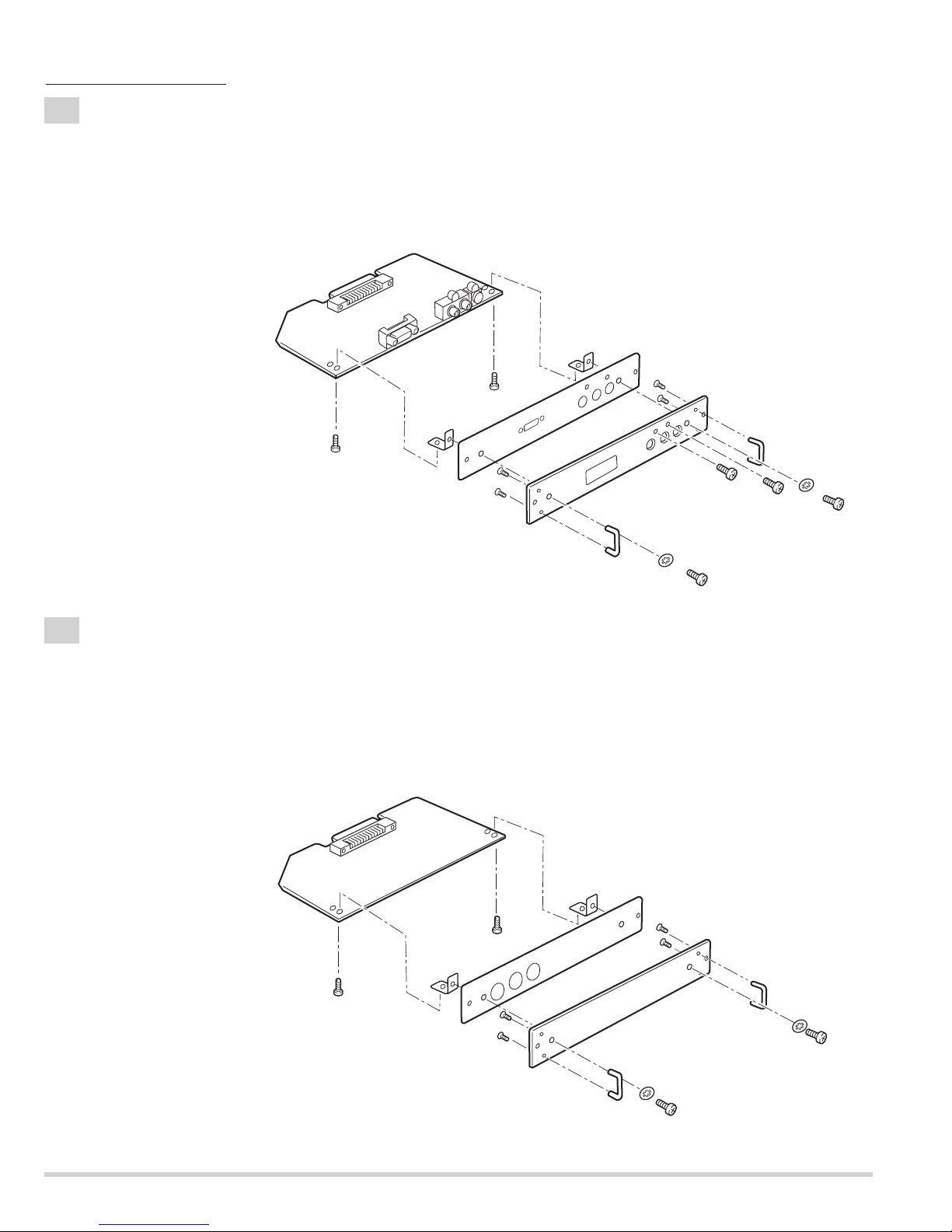
4-2
Terminal Board units and RS232C Board removal.
Fig.4-2
Fig.4-3
1. Remove 8 screws-A and remove the Terminal Board units 1-4.
2. Remove screw-B.
3. Remove 4 screws-C and remove the RS232C Board.
(See Fig.4-2)
4
-3
Terminal Slot units disassemblies.
1. Remove 2 screws-A and remove the Lamp net Board.
2. Remove 2 screws-B and remove the Holder-A.
3. Remove 3 screws-C, remove the Holder-B and remove the CG Mother Board.
4. Remove screw-D and remove Grounding Lead from the CG Mother Board.
(See Fig.4-3)
Mechanical disassemblies
C
C
C
C
RS232C Board
B
Terminal Board
units 1-4
A
A
A
A
A
A
A
A
Holder-B
C
C
B
C
CG Mother Board
A
B
Grounding Lead
D
A
Lamp net Board
Holder-A
Panel
- 21 -
Fig.4-5
Fig.4-4
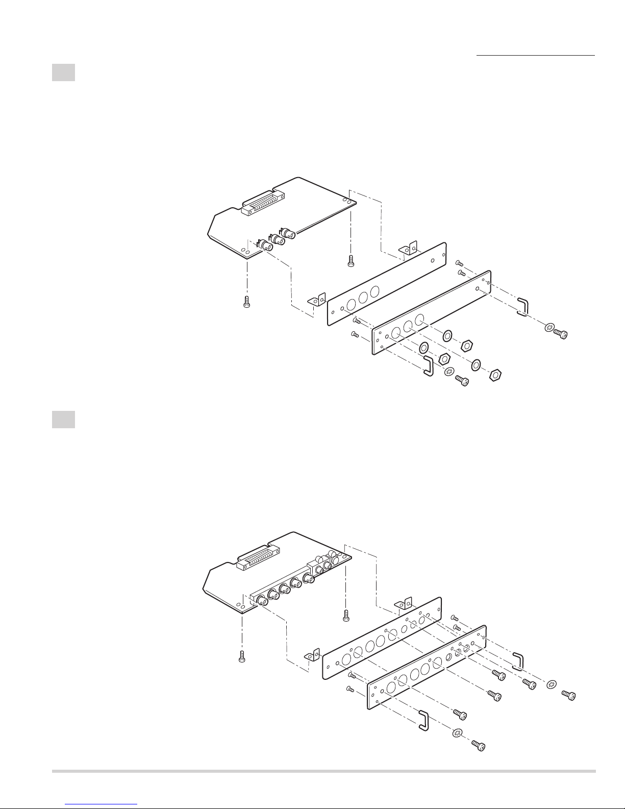
4
-5
Terminal Board Component disassemblies.
1. Remove 2 screws-A ,remove 2 screws-B, remove screw-C,remove screw-D and remove the Terminal Board
Component.
2. Remove 2 screws-E, remove 2 washers-F, remove the Holders and remove the Earth BRKT Slot.
3. Remove 4 screws-G and remove the Handles.
(See Fig.4-5)
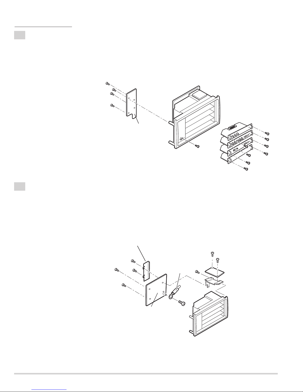
4-4
Terminal Board SDI disassemblies.
1. Remove 2 screws-A, remove 3 nuts-B, remove 3 washers-C and remove the Terminal Board SDI.
2. Remove 2 screws-D, remove 2 washers -E, remove the Holders and remove the Earth BRKT Slot.
3. Remove 4 screws-F and remove the Handles.
(See Fig.4-4)
Mechanical disassemblies
Terminal board SDI
A
Holder
Holder
F
F
Handle
A
F
Earth BRKT Slot
Terminal board Component
Holder
F
Panel
A
Handle
Holder
C
C
B
B
C
E
D
G
G
B
E
D
Handle
A
Earth BRKT Slot
G
G
Panel
Handle
C
B
B
F
E
F
D
E
- 22 -
4-6
Terminal Board DVI disassemblies.
1. Remove 2 screws-A, remove screw-B, remove screw-C, and remove the Terminal Board DVI.
2. Remove 2 screws-D, remove 2 washers-E, remove the Holders and remove the Earth BRKT Slot.
3. Remove 4 screws-F and remove the Handles.
(See Fig.4-6)
4-7
Terminal Board Earth disassemblies.
1. Remove 2 screws-A and remove the Terminal Board Earth.
2. Remove 2 screws-B, remove 2 washers-C, remove the Holders and remove the Earth BRKT Slot.
3. Remove 4 screws-D and remove the Handles.
(See Fig.4-7)
Fig.4-6
Fig.4-7
Mechanical disassemblies
Terminal board DVI
A
Holder
Holder
F
F
Handle
A
Earth BRKT Slot
Terminal board Earth
F
F
Panel
Handle
Holder
B
E
D
D
E
C
D
A
Holder
Earth BRKT Slot
A
D
D
Panel
Handle
D
Handle
C
B
C
B
- 23 -
Mechanical disassemblies
4-8
Control Switch unit disassemblies.
1. Remove 4 screws, remove the Control Button and remove the Control Board.
(See Fig.4-8)
Fig.4-8
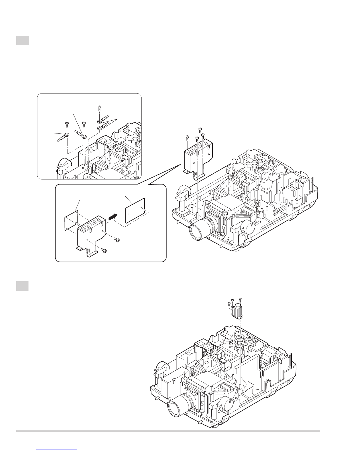
5-1
Switch Power Supply unit(5V) removal.
1. Remove 3 screws-A and remove the Switch power supply(5V) unit .
2. Remove 2 screws-B and remove the Switch power supply(5V) Board.
(See Fig.5-1, 5-1a)
Fig.5-1
Fig.5-1a
Control Button
Control Board
Switch Power Supply(5V) Board
Holder
Control Panel
A
A
B
A
Switch Power Supply(5V) unit
B
- 24 -
A
A
A
Grounding
Lead
Grounding
Lead
Grounding Lead
5-2
Switch Power Supply(25V) unit removal.
Fig.5-2
Fig.5-2a
Fig.5-2b
1. Remove 3 screws-A, and remove the grounding leads. (See Fig.5-2b)
2. Remove 4 screws-B, and remove the Switch power supply(25V) unit.
3. Remove 2 screws-C and remove the Switch power supply(25V)Board.
4. Unhook the 4 Fixer Clamps and remove the Motor &Audio Board.
(See Fig.5-2, 5-2a, 5-2b)
Mechanical disassemblies
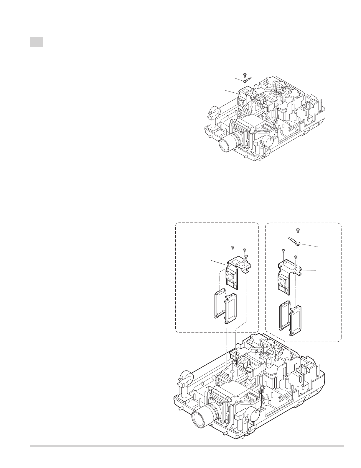
5-3
Fan(FN901) removal.
1. Remove 3 screws-A and remove the Fan(FN901).
(See Fig.5-3)
Fig.5-3
Motor and Audio
Board
The Motor and Audio Board is fixed with
holder by hook. (4places)
Switch Power Supply (25V)
Board
C
C
SW-Power supply unit(25V)
B
B
B
B
A
A
A
Fan(FN901)
- 25 -
5-4
Lamp Ballast Units removal.
1. Remove screws-C and remove the grounding lead. (Lamp ballast 3-4 unit. See Fig.5-4)
(See Fig.5-4c)
Fig.5-4
Fig.5-4c
Fig.5-4a
Fig.5-4b
Mechanical disassemblies
2. Remove screw-A and remove the grounding lead from the Holder. (Lamp ballast 1-2 unit. See Fig.5-4a)
3. Remove 2 screws-B and remove the Holder-D.
4. Remove the Lamp Ballast Unit1 and Lamp Ballast Unit2.
5. Remove 2 screws-D, remove screw-E and remove the Holder-E.
6. Remove the Lamp Ballast Unit3 and Lamp Ballast Unit4.
(See Fig.5-4, 5-4a, 5-4b,)
Grounding
Lead
Lamp ballast
3-4 unit
C
Holder -E
Ballast4
Lamp ballast 3-4
unit
D
D
E
Ballast3
Ballast2
A
B
Grounding Lead
B
Ballast1
Lamp ballast 1-2
unit
Holder -D
- 26 -
Note;
Mark the Fans as they are removed from the holder so that they may be reassembled in the same
location from which they were removed. Be careful of the attachment direction of Fans.
See arrow mark in a figure.
Ballast units may be reassembled in the same location and direction from which they were removed.
Be careful of the attached direction of Ballast units.
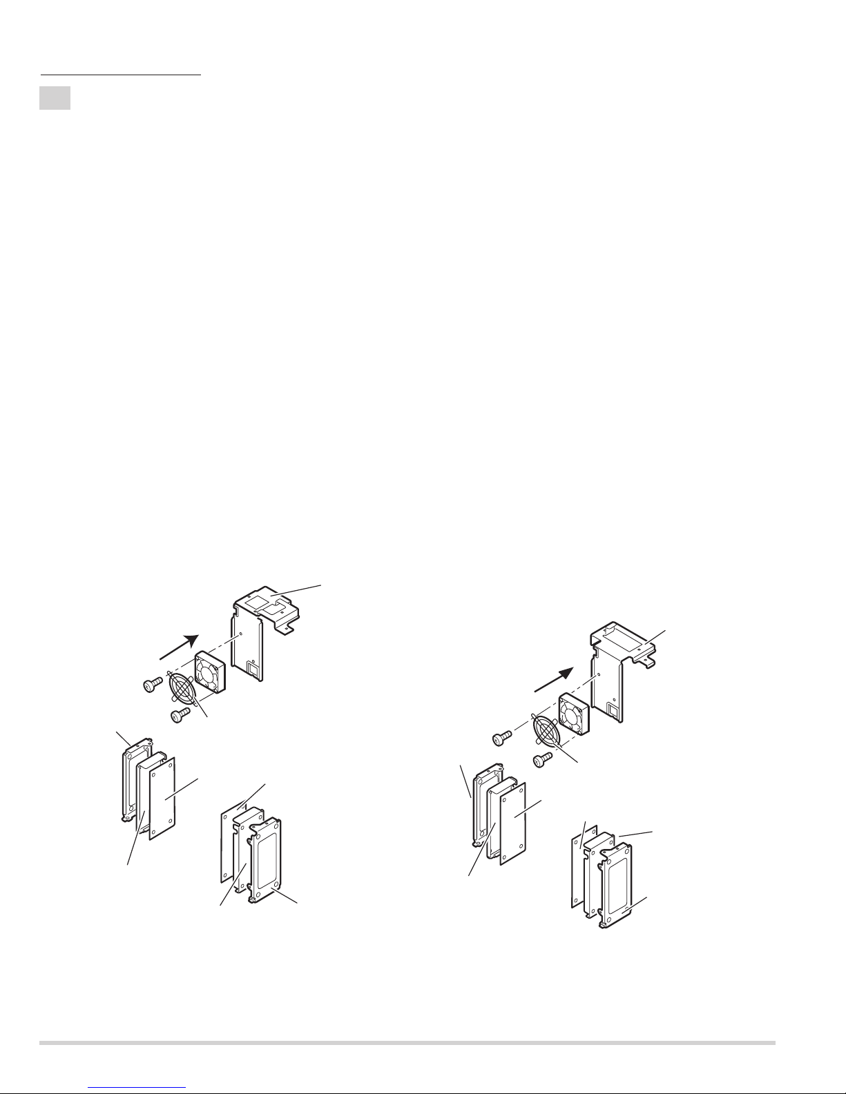
Lamp Ballast Units 1-2
1. Remove 2 screws-A, remove the Fan(FN908) and FAN Guard.
2. Remove Lamp Ballast unit 1 and remove the Spacer.
(Unhook the Fixer Clamp and remove the Lamp Ballast unit .)
3. Remove Lamp Ballast unit 2 and Spacer.
(Unhook the Fixer Clamp and remove the Lamp Ballast unit .)
(See Fig.5-5a)
Lamp Ballast Units 3-4
4. Remove 2 screws-B, remove the Fan(FN907) and FAN Guard.
5. Remove Lamp Ballast unit 3 and Spacer.
(Unhook the Fixer Clamp and remove the Lamp Ballast unit .)
6. Remove Lamp Ballast unit 4 and remove the Spacer.
(Unhook the Fixer Clamp and remove the Lamp Ballast unit .)
(See Fig.5-5b)
5-5
Lamp Ballast Units disassemblies.
Fig.5-5aFig.5-5b
Mechanical disassemblies
Holder -C
Spacer
The direction
of a wind.
(FN907)
B
Ballast 4
FN907
FAN GUARD
B
Spacer
Ballast 3
Holder
Holder -E
A
Holder-C
Spacer
The Ballast Board is being fixed with
Holder by hook. (4places)
The direction
of a wind.
(FN908)
A
Ballast 2
Holder-D
FN908
FAN GUARD
Ballast 1
Spacer
Holder-C
- 27 -
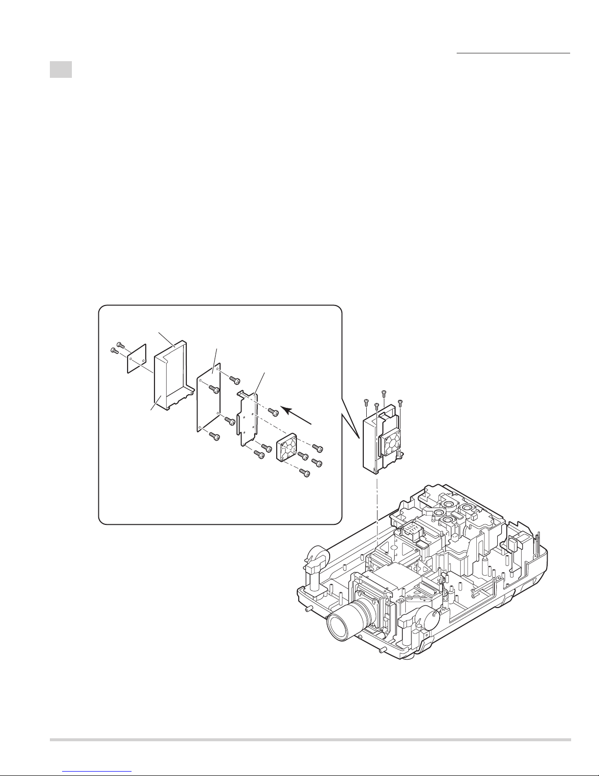
5-6
PFC Unit 3-4 and Power Unit removal.
PFC Unit 3-4 removal.
1. Remove 4 screws-A and remove the PFC 3-4 Unit.
2. Remove 4 screws-B and remove the Fan (FN914).
3. Remove 3 screws-C and remove the Holder FN.
4. Remove 4 screws-D and remove the PFC 3-4 Board.
5. Remove 2 screws-E and remove the AC net Board.
(See Fig.5-6, 5-6a)
Note;
Mark the Fans as they are removed from the holder so that they may be reassembled in the same location from
which they were removed.Be careful of the attached direction of Fan.
See arrow mark in a figure.
PWB units may be reassembled in the same location and direction from which they were removed. Be careful of
the attached direction of PWB units.
Fig.5-6
Fig.5-6a
Mechanical disassemblies
AC net Board
E
E
PFC3-4 Board
Holder PFC
Holder FN
D
D
D
D
C
The direction
of a wind.
(FN914)
C
C
A
A
B
B
B
B
A
A
PFC3-4 unit
- 28 -
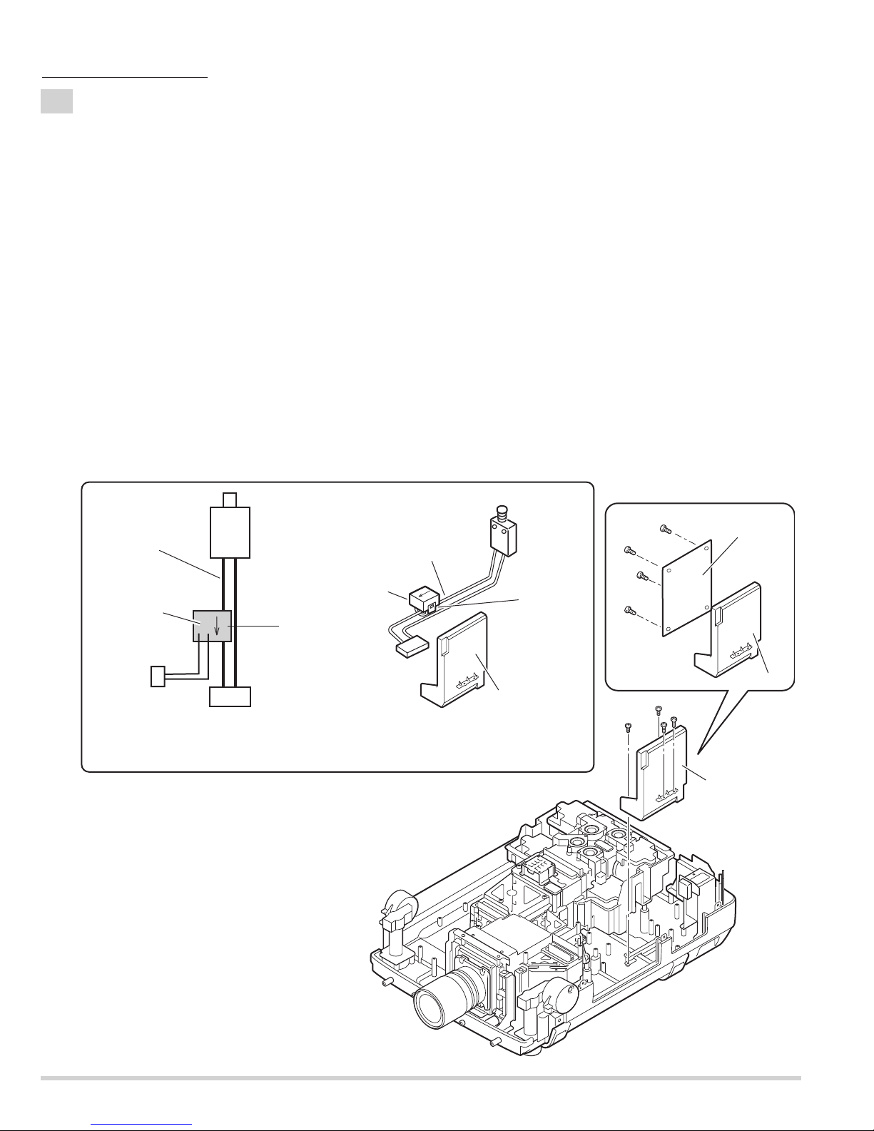
5-7
Current sensor removal and replacement.
Power unit
Ass'y Power unit
K6A
Current sensor
Current
sensor
K
L
K96W
Inter lock switch
SW902
Unhook
Blue lead wire
Blue lead wire
K6A
SW902
(a)
Printed mark
A903
1. Unhook the part(a) and remove the current sensor.
Note:The way of installing a current sensor is very important on the performance and the safety. Install in the
condition which is the same as the time of disassemble.
Replacement
1. The Current sensor is attached in the blue lead wire between an interlock switch (SW902) and power unit
(K6A).
2. The Current sensor (L) side is attached in the k6a side.
Refer to schematic diagrams (page-S1).
PWB units may be reassembled in the same location and direction from which they were removed. Be careful of the
attached direction of PWB units.
Power Unit removal.
Power Unit removal.
1. Remove 2 screws-A, remove 2 screws-B and remove the Power Unit.
2. Remove 4 screws-C and remove the Power Board.
(See Fig.5-7, 5-7a)
Fig.5-7b
Fig.5-7a
Fig.5-7
Mechanical disassemblies
C
C
C
C
A
A
B
B
Power Board
Holder Power
Power unit
- 29 -
5-8
PFC 1-2 Unit and Sub Power Unit removal.
PFC 1-2 Unit removal.
1. Remove 4 screws-A and remove the PFC 1-2 Unit.
2. Remove 2 screws-B and remove the Holder FAN.
3. Remove the Fan (FN913).
4. Remove 4 screws-C and remove the PFC 1-2 Board.
(See Fig.5-8, 5-8a)
Sub Power Unit removal.
5. Remove 4 screws-D and remove the Sub Power Unit.
6. Remove 6 screws-E and remove the Sub Power Board.
(See Fig.5-8, 5-8b)
Note;
Mark the Fans as they are removed from the holder so that they may be reassembled in the same location from
which they were removed. Be careful of the attachment direction of Fan.
See arrow mark in a figure.
PBW units may be reassembled in the same location and direction from which they were removed. Be careful of
the attached direction of PWB units.
Fig.5-8
Fig.5-8a
Fig.5-8b
Mechanical disassemblies
Sub Power Board
Holder Sub power
E
E
E
E
E
E
Holder PFC1-2
PFC 1-2 Board
C
The direction
C
C
D
D
D
D
Sub power
Unit
A
A
C
A
A
PFC1-2 Unit
of a wind.
(FN913)
Holder FAN
B
B
- 30 -
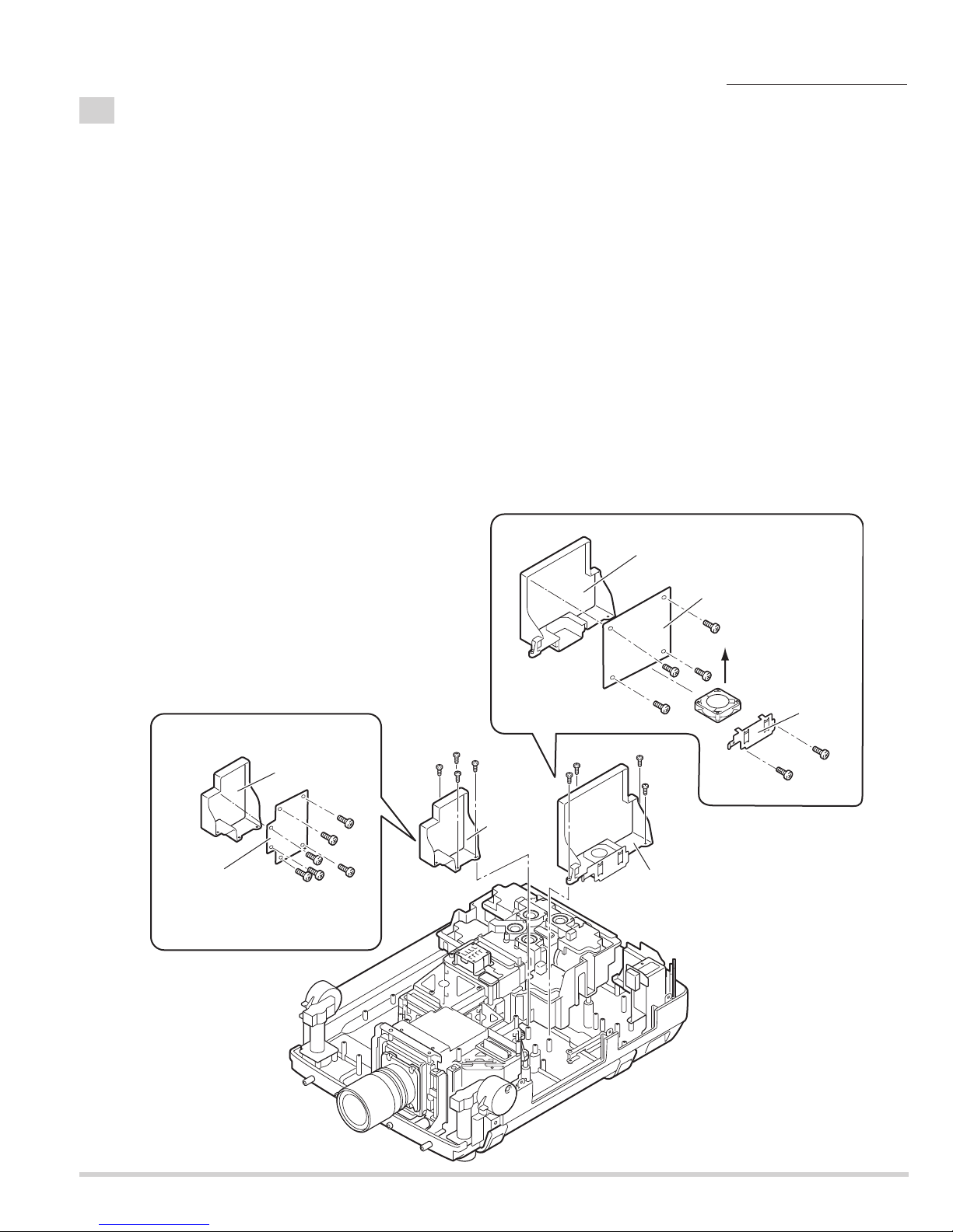
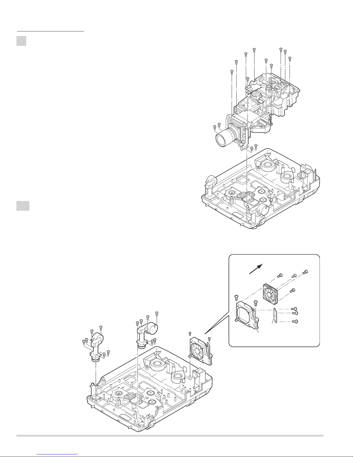
6
Optical Unit removal.
1. Remove 10 screws-A, remove 4 screws-B and remove the Optical unit.
(See Fig.6)
Note;
Do not hold the projection lens.
It may damage projection lens.
7-1
Fan(FN906) Unit and Adjustable-feet removal.
1. Remove 6 screws-A and remove the Adjustable-foot-left.
2. Remove 6 screws-B and remove the Adjustable-foot-right.
3. Remove 2 screws-C and remove the Fan(FN906) Unit.
4. Remove 4 screws-D and remove the Fan(FN906).
5. Remove 3 screws-E and remove the Rear LED Board.
(See Fig.7-1, 7-1a)
Note;
Mark the Fans as they are removed from the holder so that they may
be reassembled in the same location from which they were removed.
Be careful of the attached direction of Fans.
See arrow mark in a figure.
Fig.6
Fig. 7-1
Fig. 7-1a
Mechanical disassemblies
A
A
A
A
A
A
A
A
A
A
A
A
A
A
Adjustable
foot-left
A
Adjustable
foot-right
A
B
B
B
B
Optical Unit
D
D
E
E
E
D
D
The direction
of a wind
FN906
C
C
B
B
B
B
C
B
B
C
Fan(FN906) unit
Rear LED Board
Holder FN
 Loading...