

Sanyo PLV-80,PLV-80L,PLV-75,PLV-75L Service Manual
FILE NO.
SERVICE MANUAL
Multimedia Projector
Model No. PLV-80, PLV-80L
U.S.A., Canada,
Europe, Asia, Africa
Original Version
* PLV-80L does not provide a projection lens.
PRODUCT CODE
PLV-80 PLV-80L
1 122 318 00
(M4YA) 1 122 318 20 (M4YAL)
1 122 319 00 (P4YA) 1 122 319 20 (P4YAL)
1 122 319 02 (P4YC) 1 122 319 22 (P4YCL)
Chassis No. M4Y-8000
M4Y-80L00
NOTE: Match the Chassis No. on the unit's
back cover with the Chassis No. in
the Service Manual.
If the Original Version Service
Manual Chassis No. does not
match the unit’s, additional Service
Literature is required. You must refer
to “Notices” to the Original Service
Manual prior to servicing the unit.
REFERENCE NO. SM5110755-00

Contents
SERVICE MANUAL ................................................... 1
Contents ........................................................................ 2
Safety Instructions .........................................................
SAFETY PRECAUTIONS ...........................................
PRODUCT SAFETY NOTICE ....................................
SERVICE PERSONNEL WARNING ...........................
Specifications ................................................................
Circuit Protections .........................................................5
Fuse ............................................................................ 5
Thermal switch ...........................................................
Interlock switch ...........................................................
Warning temperature and power failure protection .....
Air filter care and cleaning ..........................................
Lamp Replacement .......................................................7
How to reset Lamp Replace Counter .........................
How to check Lamp use time ......................................
Mechanical Disassemblies ............................................
Optical Parts Disassemblies ........................................
LCD Panel/Prism Ass’y Replacement .........................
Adjustments ................................................................. 19
Turning On the Projector ...........................................
Adjustments after Parts Replacement ......................
Optical Adjustments ..................................................... 20
Electrical Adjustments .................................................
Service Adjustment Menu Operation ........................
Memory IC Replacement (IC802) .............................
Circuit Adjustments ................................................... 24
Test Points and Locations .........................................
Service Adjustment Data Table .................................
Chassis Description .....................................................
Block Diagrams .........................................................
Chassis over view .....................................................
Input & video precessing stage ................................ 46
LCD panel driving stage ...........................................
Audio signal precessing stage ..................................
Lamp control stage ................................................... 49
Fan control stage .....................................................
Motor control stage .................................................. 51
Serial
bus control stage ........................................... 52
13
18
19
19
23
23
23
27
28
45
45
45
47
48
50
Power supply control & power failure detection ........
LED indicators and projector condition ..................... 54
Power f
3
Power failure detection tree ......................................
3
Error History Log ......................................................
3
3
Diagnosis of Power Failure with RS-232C port ......... 58
4
Diagnosis procedure ................................................. 58
Error information table ..............................................
Control Port Functions .................................................
System Control & I/O Port Table ...............................
5
5
Cleaning ......................................................................67
IC Block Diagrams .......................................................
6
Electrical Parts List ......................................................
6
Mechanical Parts List ................................................
Cabinet Parts Location ...........................................
7
7
Optical Parts Location ............................................ 109
8
Mecanical Parts List ............................................... 113
Diagrams & Drawings ..................................................
Parts description and reading in schematic diagram ...
Schematic Diagrams ...........................................
Printed Wiring Board Diagrams .........................
Pin description of diode, transistor and IC .................
ailure detection system ................................ 55
53
56
57
59
60
60
68
77
108
108
A1
A2
A3-A10
A11-A16
A17
-2-
Safety Instructions
SAFETY PRECAUTIONS
WARNING:
The chassis of this projector is isolated (COLD) from AC line by using the converter transformer. Primary side
of the converter and lamp power supply unit circuit is connected to the AC line and it is hot, which hot circuit is
identified with the line (
nel injury, servicing should be made with qualified personnel.
The following precautions must be observed.
) in the schematic diagram. For continued product safety and protection of person-
1: An isolation transformer should be connected in the
power line between the projector and the AC line
before any service is performed on the projector.
2: Comply with all caution and safety-related notes
provided on the cabinet back, cabinet bottom, inside
the cabinet or on the chassis.
3: When replacing a chassis in the cabinet, always
be certain that all the protective devices are
installed properly, such as, control knobs, adjust
ment covers or shields, barriers, etc.
DO NOT OPERATE THIS PROJECTOR WITHOUT T
HE PROTECTIVE SHIELD IN POSITION AND PROP
ERLY SECURED.
4: Before replacing the cabinet cover, thoroughly
inspect the inside of the cabinet to see that no
stray parts or tools have been left inside.
Before returning any projector to the customer, the
service personnel must be sure it is completely safe
-
to operate without danger of electric shock.
PRODUCT SAFETY NOTICE
Product safety should be considered when a component replacement is made in any area of the projector.
Components indicated by mark ! in the parts list and the schematic diagram designate components in which
safety can be of special significance. It is, therefore, particularly recommended that the replacement of there
parts must be made by exactly the same parts.
Eye damage may result from directly viewing the light produced by the Lamp used in this equipment. Always
turn off Lamp before opening cover. The Ultraviolet radiation eye protection required during this servicing.
Never turn the power on without the lamp to avoid electric-shock or damage of the devices since the stabilizer
generates high voltages(15kV - 25kV) at its starts.
Since the lamp is very high temperature during units operation replacement of the lamp should be done at least
45 minutes after the power has been turned off, to allow the lamp cool-off.
SERVICE PERSONNEL WARNING
-3-
Specifications
Projector Type Multi-media Projector
Dimensions (W x H x D) 12.6” x 6.6” x 16.8” (319mm x 168mm x 429.5mm)
Net Weight 19.2 lbs (8.7 kg) PLV-80, 16.3 lbs (7.4 kg) PLV-80L
LCD Panel System 1.21” TFT Active Matrix type, 3 panels
Panel Resolution 1366 x 768 dots
Number of Pixels 3,147,264 (1366 x 768 x 3 panels)
Color System 6 color system (PAL, SECAM, NTSC, NTSC4.43, PAL-M and PAL-N)
High Definition TV SIgnals 480i, 480p, 575i, 575p, 720p. 1035i and 1080i
Scanning Frequency H-sync. 15 ~ 100kHz, V-sync. 50 ~ 100Hz
Projection Image Size (diagonal) Adjustable from 31” to 400”
Horizontal Resolution 800 TV lines (HDTV)
Projection Lens F 1.8 ~2.1 lens with f=48.4mm ~ 62.8mm with motor zoom and focus
Throw Distance 5.0’ ~ 51.3’ (1.5m ~ 15.6m)
Motorized Lens Shift Up and Down
Projection Lamp 300 watts
Input 1 Jacks DVI Terminal (Digital), HDB 15-pin Terminal (Analog) and Stereo Mini Type
Jack (Audio)
Input 2 Jacks BNC Type x 5 (G or VIDEO/Y, B or Cb/Pb, R or Cr/Pr, H and V), Stereo
Mini Type Jack (Audio)
Input 3 Jacks RCA Type x 3 (VIDEO/Y, Cb/Pb, Cr/Pr), RCA Type x 2 (Audio R and L) and
DIN 4-pin (S-Video)
Other Jacks DIN 8-pin (Control port), Wired Remote Jack and Network Board Connector
Jack
Built-in Speakers 2 speakers Stereo (R and L), 2 watts RMS (T.H.D. 10%)
Feet Adjustment 0˚ to 10.5˚
Voltage and AC 100 ~ 120V (3.6A Max. Ampere), 50/60Hz (The U.S.A and Canada)
Power Consumption AC 200 ~ 240V (1.8A Max. Ampere), 50/60Hz (Continental Europe and the U.K)
Operating Temperature 41 ˚F ~ 95 ˚F (5˚C ~ 35˚C)
Storage Temperature 14 ˚F ~ 140 ˚F (-10˚C ~ 60˚C)
● The specifications are subject to change without notice.
This symbol on the nameplate means the product is Listed by Underwriters
Laboratories Inc. It is designed and manufactured to meet rigid U.L. safety standards against risk of fire, casualty and electrical hazards.
-4-
Circuit Protections
This projector is equipped with the following circuit protections to operate in safety. If the abnormality occurs inside
the projector, it will automatically turn off by operating one of the following protection circuits.
Fuse
The fuse is located inside of the projector. When either the
LAMP indicator or the READY indicator is not illuminated, fuse
may be opened. Check the fuse as following steps.
It should be used the specified fuse as follows;
Fuse Part No.: 423 025 1201
TYPE T8AH 250V FUSE
LITTEL FUSE INC. TYPE 215008
How to replace the fuse
1. Remove the cabinet top following to “Mechanical
Disassemblies”.
2. Remove the fuse from fuse holder.
To install the fuse, take reversed step in the above.
Fuse
Line Filter Board
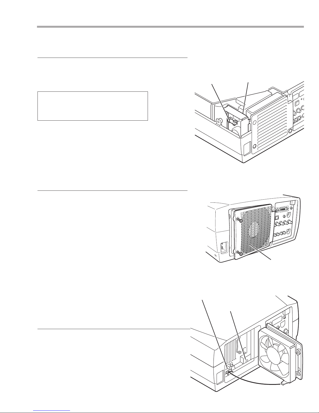
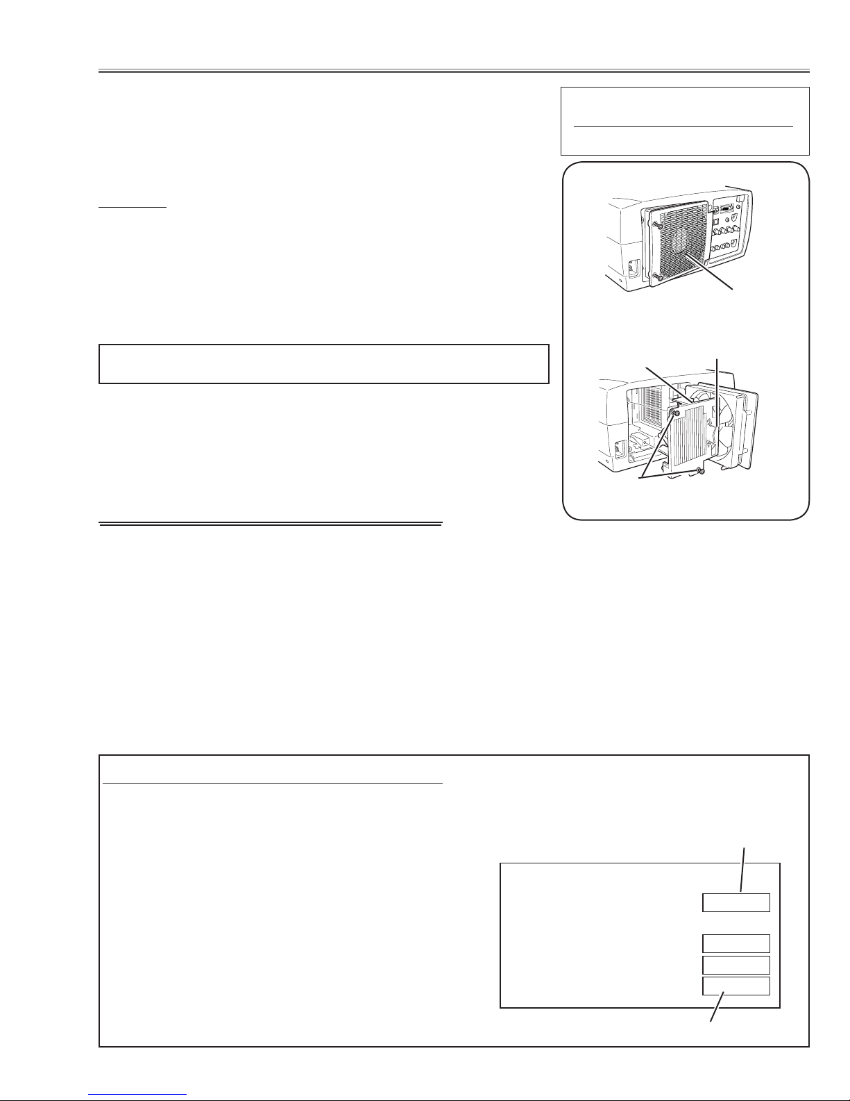
Thermal switch
There is the thermal switch (SW905) inside of the projector to
prevent the internal temperature from rising abnormally. When
the internal temperature reaches near 90˚C, turn off the AC main
power supply automatically.
The thermal switch is not reset to normal automatically even if
the internal temperature becomes normal. Reset the thermal
switch following procedure.
Check the resistance between terminals of thermal switch by
using the tester. If it has high impedance, thermal switch may be
in operative.
How to reset the thermal switch
1. Loosen 2 screws and open the lamp cover.
2. Press the reset button on the thermal switch with a sharp-
pointed tool.
CAUTION:
Before press the reset button, disconnect the AC cord from the
projector.
Interlock switch
The interlock switch (SW902) cuts off the AC mains power supply when the lamp cover is removed. After opening the lamp
cover for replacing the lamp ass’y, place the lamp cover correctly
otherwise the projector can not turn on.
Lamp cover
Interlock switch
Thermal switch
-5-
Circuit Protections
Warning temperature and power failure protection
The TEMP WARNING indicator flashes red and the projector will automatically turn off when the internal temperature of the projector exceeds the normal temperature or when stopping cooling fans or when the internal power
supply lines are failed.
Check the following possible causes and wait until stopping the TEMP WARNING indicator flashing.
Possible causes
- Air filter is clogged with dust particles. Remove dust from the air filter by following instructions in the “Air filter care
and cleaning” below.
- Ventilation slots of the projector are blocked. In such an event, reposition the projector so that ventilation slots are
not obstructed.
- Check if projector is used at higher temperature place (Normal operating temperature is 5 to 35 ˚C or 41 to 95˚F)
If the TEMP WARNING indicator still continues to flash, there may be defects on cooling fans or power supply cir
cuits. Please check fan operation and power supply lines referring to the “Power Supply Lines Chart”.
-
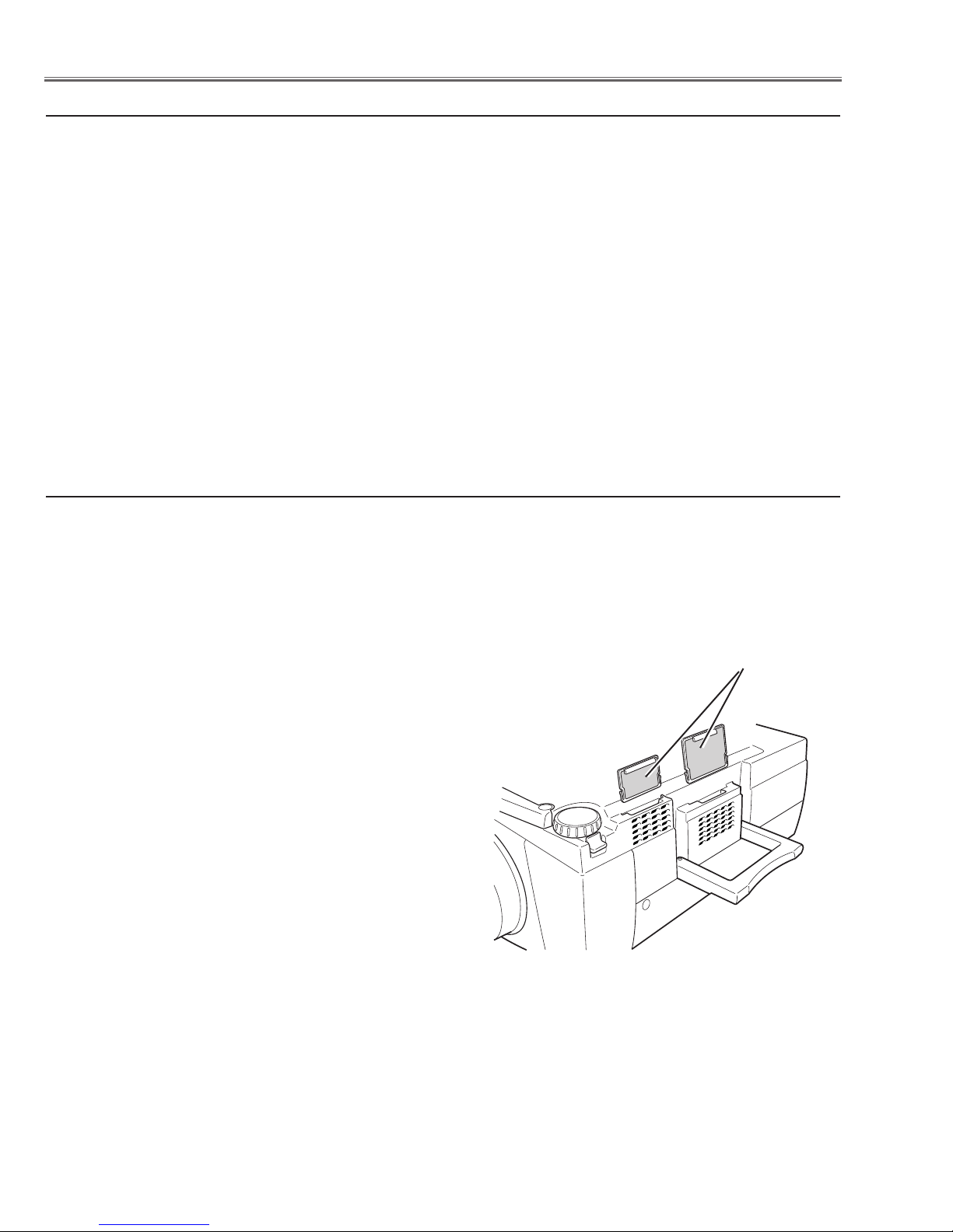
Air filter care and cleaning
The removable air filter prevents dust from accumulation on the surface of the projection lens and projection mirror.
Should the air filter become clogged with dust particles, it will reduce the cooling fan’s effectiveness and may result
in internal heat build up and reduce the life of the projector.
To clean up the air filters, follow the cleaning procedure
below:
1. Turn the power off, and disconnect the AC power cord
from the AC outlet.
2. Turn the projector up side down and remove an air fil-
ters by pulling the latches of them upward.
3. Clean the air filters with brush or wash out the dust and
particles.
4. Replace each air filter properly. Make sure that the air
filters are fully inserted.
Air filters
CAUTION:
Do not operate the projector with the air filter removed. The
dust is stuck on the LCD panel and the mirror, and it may
spoil the fine picture image.
Do not put the small parts into the air intake vents. It may
result in the malfunction of the projector. The air filter is
small parts. Take care that children don’t eat or swallow it.
RECOMMENDATION
We recommend to avoid dusty, smoky place for operating the projector. Using in dusty place may cause the picture
of poor quality.
When using under the dusty or smoky conditions, dust may accumulate on the LCD panel and lens inside it, and
may resultantly be projected on the screen together with the picture.
When the above symptoms are noticed, please clean up the LCD panel and lens following to the “Cleaning
Method”.
-6-
Lamp Replacement
Counter
Projector 525H
Lamp
Normal 150H
Eco
375H
Corresponding value 575H
WARNING:
- For continued safety, replace with a lamp assembly of the same type.
- Allow the projector to cool for at least 45 minutes before you open the
lamp cover. The inside of the projector can become very hot.
- Do not drop the lamp module or touch the glass bulb! The glass can
shatter and cause injury.
Procedure
1 Turn off the projector and disconnect the AC cord. Allow the projector to
cool for at least 45 minutes.
2 Loosen 2 screws with a screwdriver and open the lamp cover.
3 Loosen 2 screws and pull out the lamp assembly by grasping the han-
dle.
4 Replace the lamp assembly securely and tighten 2 screws.
5 Close the lamp cover and tighten 2 screws.
6 Connect the AC cord to the projector and turn on.
7 Reset the Lamp Replace Counter, see below explanation.
Note:
- Do not reset the Lamp Replace Counter, except after lamp is replaced.
- The projector can not be turned-on with lamp cover removed, because
when the lamp cover is removed, the interlock switch is also released to
switch off the mains power for safety.
ORDER REPLACEMENT LAMP
Type No. Service Parts No.
POA-LMP98 610 325 2957
Lamp cover
Handle
Lamp Assembly
Screws
How to reset Lamp Replace Counter
1 Turn the projector on, and press the MENU but-
ton and the on-screen menu will appear. Press the
POINT LEFT/RIGHT buttons to move a red frame
pointer to SETTING menu icon.
2 Press the POINT DOWN button to move a red frame
pointer to “Lamp counter reset” and then press the
SELECT button. The message “Lamp replace counter reset?” is displayed. Move the pointer to [Yes] and
the press the SELECT button.
3 Another confirmation dialog box appears and select
[Yes] to reset Lamp Replace Counter .
Please refer to the owners manual for further information.
How to check Lamp use time
The LAMP REPLACE indicator will light red when the
total lamp used time (Corresponding value) reaches
2000 hours. This is to indicate that lamp replacement
is required.
The total lamp used time is calculated by using the below expression,
Total lamp used time = Teco + Tnormal (1 + 1/3)
Teco: used time in the Eco mode
Tnormal : used time in the Normal mode
You can check the lamp used time following to the below
procedure.
1 Press and hold the POWER ON-OFF button on the
projector for more than 20 seconds.
2 The projector used time and lamp used time will be
displayed on the screen as follows.
Recommendation
Should the air filter become clogged with dust particles, it will reduce the cooling fan’s effectiveness and
may result in internal heat build up and short lamp life.
We recommend cleaning the air filter after the projection lamp is replaced.
Refer to “Air Filter Cleaning”.
Press MENU button to disappear the screen display.
Projector used time
Total lamp used time
-7-
UP
Mechanical Disassemblies
Mechanical disassemble should be made following procedures in numerical order.
Following steps show the basic procedures, therefore unnecessary step may be ignored.
Caution:
The parts and screws should be placed exactly the same position as the original otherwise it may cause loss of
performance and product safety.
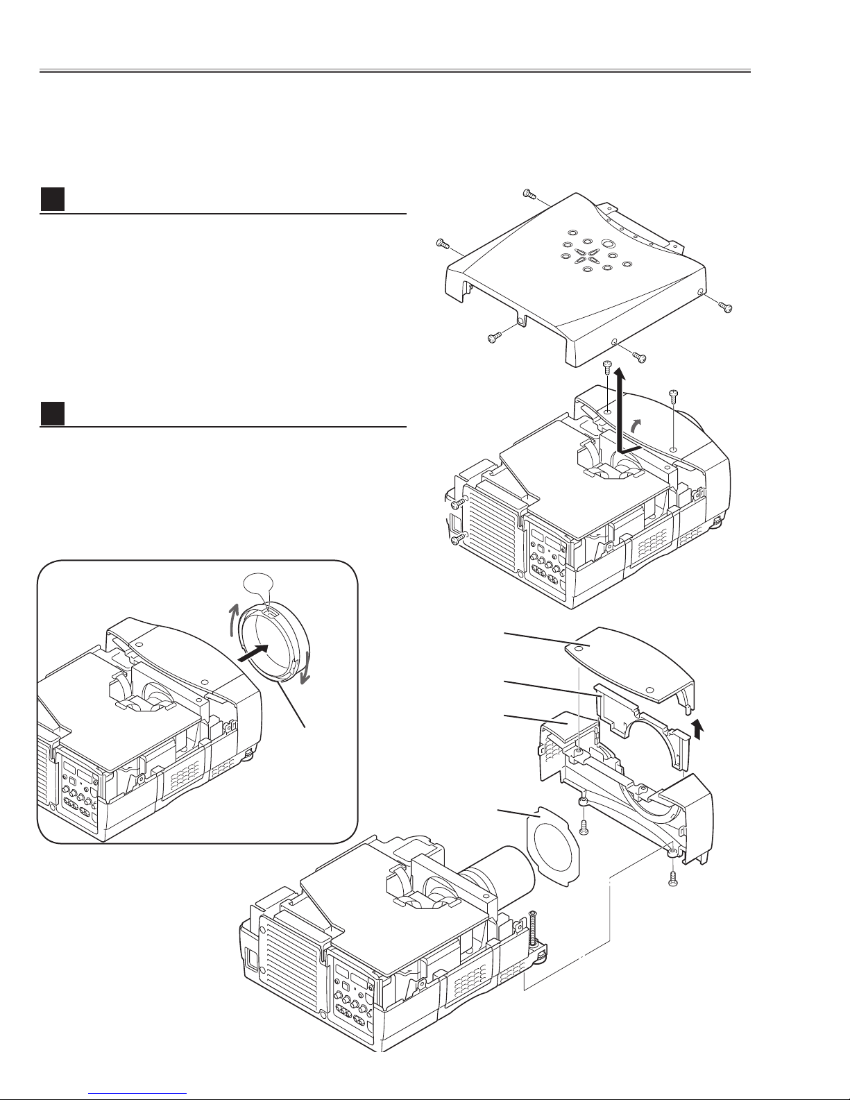
1
Cabinet Top removal
1 Remove 5 screws A, 2 screws B, and loosen 2 screws C,
and then take the Cabinet Top upward off.
Note: If you want to remove the Cabinet Front-Top only,
you do not need to remove screws
and Lens Front Cover.
2
Cabinet Front removal
A. Remove 2 screws B
1 Turn the Lens Front Cover counter-clockwise and to take
it off by pulling forward as shown in Fig.2-1.
2 Remove the Cabinet Front-Top, Lens Cover Holder and
Lens Cover upward off.
3 Remove 2 screws D to take the Cabinet Front off.
4 Remove the RC Board and speakers on the Cabinet
Front.
A
A
A
A
B
C
C
A
B
Fig.1
Cabinet Front-Top
Lens Cover Holder
Cabinet Front
Lens
Front
Cover
Lens Cover
Fig.2-1
D
D
Fig.2-2
-8-
Mechanical Disassemblies
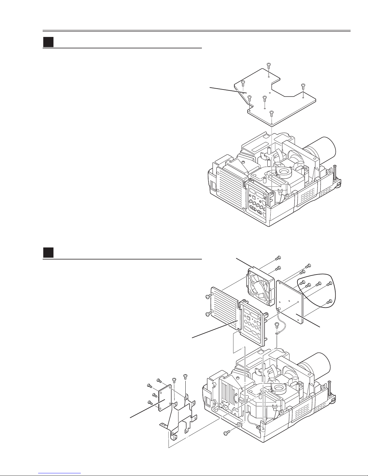
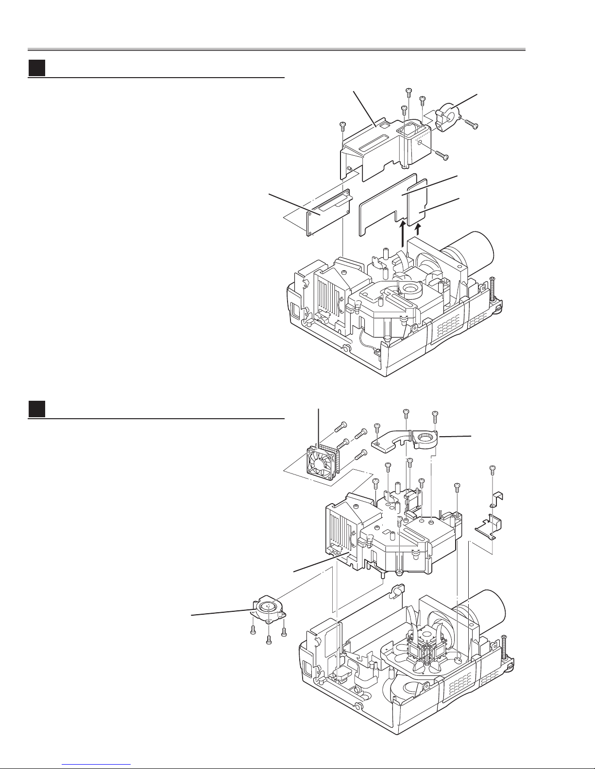
3
Main Board removal
1 Remove 6 screws to take the Main Board upward.
Main Board
4
AV, I/F Board & Rear Panel removal
1 Remove 1 screw A and take the Rear Panel ass’y
upward off.
2 Remove 4 screws B to take the fan (FN905) off.
3 Remove 5 screws C and 1 screw D to take AV Board
from the Rear Panel ass’y off.
4 Remove 2 screws E and grounding leads and then pull
up the I/F Board and Holder assy from the bottom cabi
net.
5 Remove 4 screws F to take the I/F Board.
Rear Panel Ass’y
E
F
F
F
F
E
Fig.3
FN905
-
B
B
D
B
B
C
AV Board
I/F Board
A
Fig.4
-9-
Mechanical Disassemblies
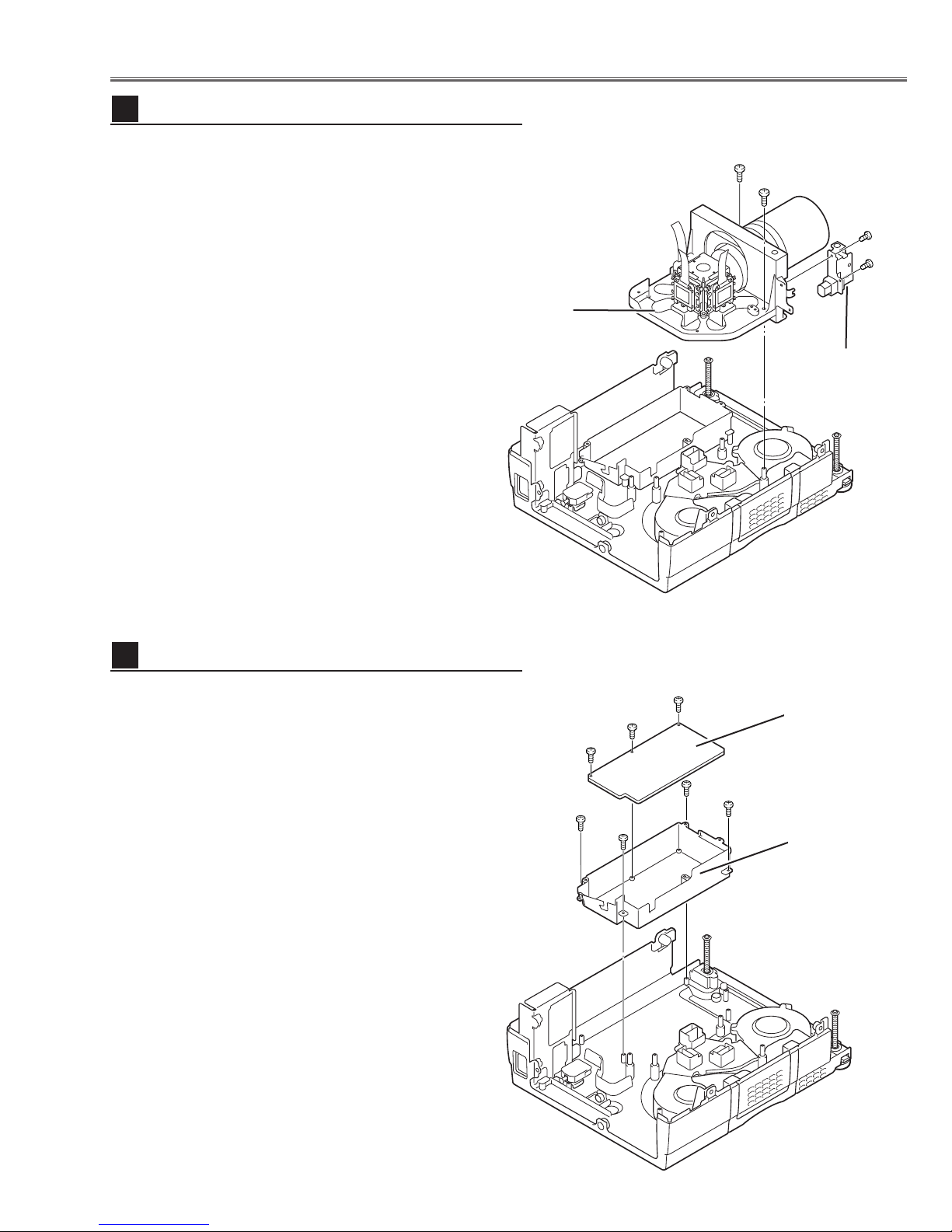
5
Lamp Ballast Unit removal
1 Remove 4 screws A to take the Ballast Cover upward
off.
2 Remove 2 screws B to take the Fan (FN904) off.
3 Remove the Sub Power Board and Drive Board by pull-
ing them upward.
Ballast Board
Ballast Cover
A
A
A
A
FN904
B
B
Sub Power
Board
Drive Board
6
Optical Unit removal
1 Remove 1 screw A and then remove the holders.
2 Remove 2 screws B and 4 screws C(small) and pull the
Optical Unit upward off.
3 Remove 4 screws D to take the Fan (FN906) off.
4 Remove 1 screws E to take the Fan (FN903) off and 2
screws
F to take the air duct off.
5 Remove 3 screws G to take the Fan (FN907) off.
Optical Unit
FN907
G
G
Fig.5
FN906
D
D
D
B
G
F
F
C
B
E
FN903
C
C
C
A
Fig.6
-10-
Mechanical Disassemblies
7
Prism Base removal
1 Remove 2 screws A to take the Prism Base ass’y
upward off.
2 Remove 2 screws B to take the Lens Shift Motor and
Sensor SW Holder from the Base.
Prism Base Ass’y
A
A
B
B
Motor and
Sensor Holder
8
Power Board removal
1 Remove 3 screws A to take the Power Board off.
2 Remove 4 screws B to take Holder off from the cabinet
bottom.
Fig.7
A
A
A
B
B
B
B
Power Board
Power Board
Holder
Fig.8
-11-
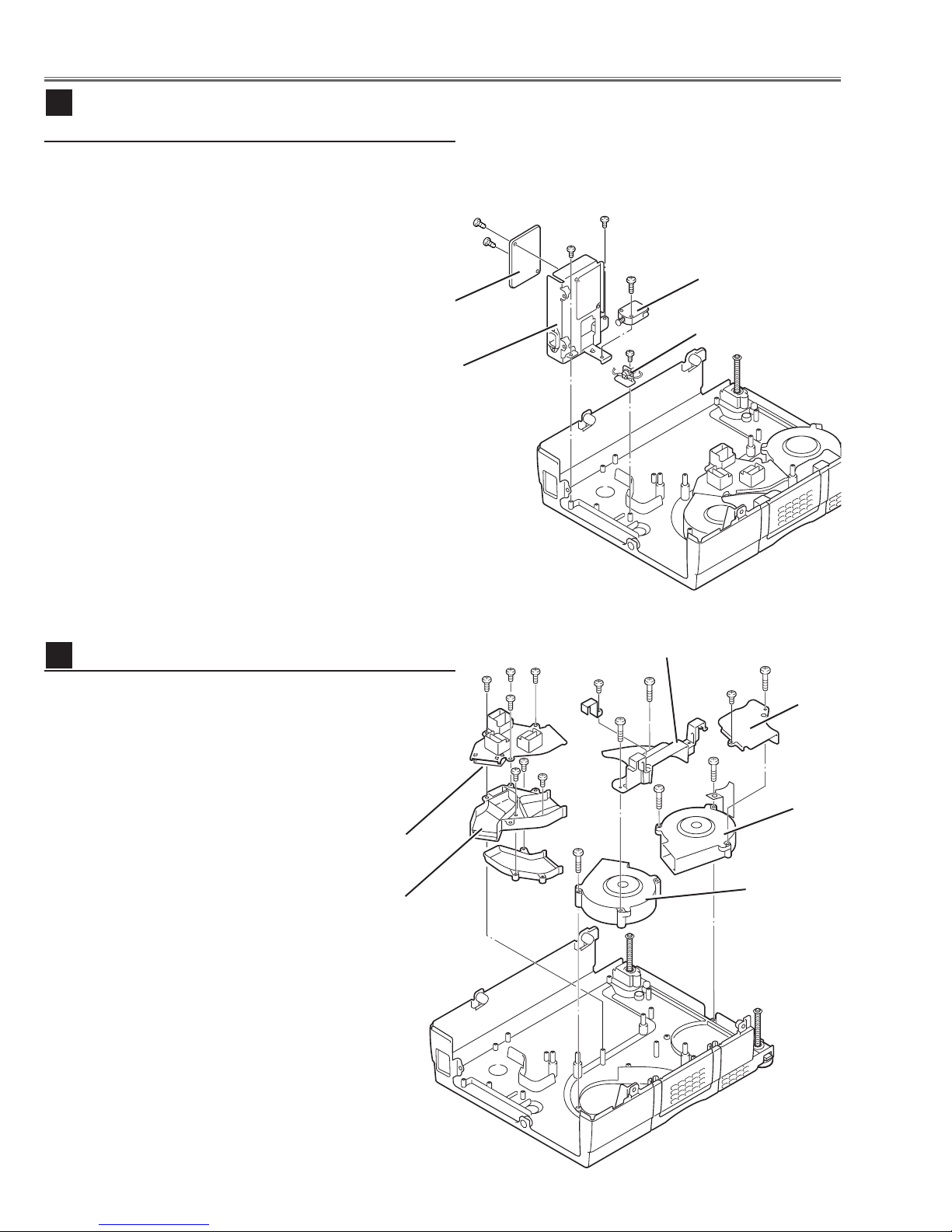
Mechanical Disassemblies
9
Line Filter Board & Interlock SW & Thermal
SW removal
1 Remove 1 screw A to take Interlock Switch(SW905).
2 Remove 2 screws B to take Filter Board Holder and
remove 2 screws
C to take Filter Board from the Holder.
3 Remove 1 screw D to take Thermal Switch(SW902).
C
C
B
B
A
Interlock Switch
(SW905)
Filter Board
Holder
10
Fans (FN901, FN902) removal
1 Remove 4 screws A to take Air-duct Top off.
2 Remove 1 screw B (small) and 1 screw C (big) to take
Duct Cover-A.
3 Remove 2 screws D to take Fan (FN901) off.
4 Remove 1 screw E (small) and 2 screws F (big) to take
Air-duct-A and Fan (FN902) off.
Thermal Switch
D
(SW902)
Fig.9
Air-duct-A
A A
A
A
E
F
F
D
D
C
B
Duct
Cover
-A
FN901
Air-duct
Top
Duct
Cover-B
F
FN902
Fig.10
-12-

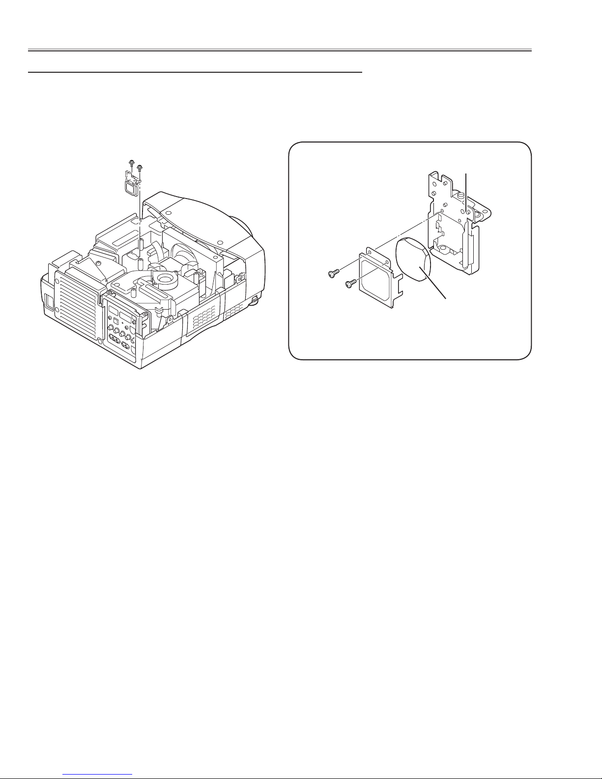
Optical Parts Disassemblies
Optical Filter(WV)
Polarized Grass
1
A
V
4
Z
1
5
*
*
*
1
A
V
4
Z
1
5
*
*
*
Part No.
Part No.
Film side
Film side
Before taking this procedure, remove Cabinet Top and Main Board following to the “Mechanical Disassemblies”.
Disassembly requires a 2.0mm or 2.5mm hex wrench and a slot screwdriver.
Projection Lens removal
1 Remove Cabinet Front-Top following to the chapter “Mechanical
Disassemblies”.
2 Loosen 2 screws A with 2.5mm hex wrench.
3 Unhook 2 hooks B on the both side of the lens and remove the Projection
Lens ass’y off.
B
A
B
A
Fig.1
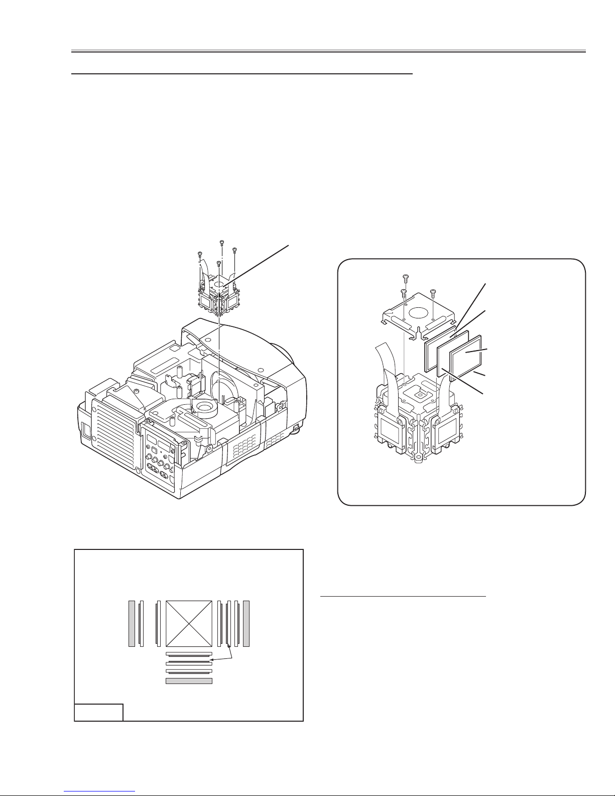
Polarized Glass-In and Optical filter removal
1 Remove each hex screw and pull the Polarized Glass-In ass’y upward.
2 Remove the stoppers and take the glasses off.
* The B-Plolarised Glass-In ass'y does not provide the Optical filter.
Fig.1-2
Fig.2-1
-13-
* Glasses should be placed as the
film sheet attached side comes to
LCD panels side.
Fig.2-2
Optical Pats Disassemblies
Relay Lens disassembly
1 Remove 2 hex screws A and pull the Relay Lens ass’y upward.
2 Remove 2 screws B to take the Lens off from the holder.
Note:
There is no mounting direction of the lens.
A
A
Holder
B
B
Relay Lens
Fig.3-1
Fig.3-2
-14-
Optical Pats Disassemblies
LCD Panel/Prism Assembly
LCD PANEL
(GREEN)
LCD PANEL
(BLUE)
LCD PANEL
(RED)
1245
2345
32 4 5
Phase Sheet
(*2)
TOP VIEW
Polarized Glass-Out and Optical Filter(WV) removal
1 Remove 4 hex screws A and take the LCD/Prism ass’y off upward.
2 Remove 3 screws B and take the Glass Holder, and then pull the
Polarized Glass-Out, Pre-polarized Glass-Out and Optical Filter(WV)
upward off. These glasses are mounted for R, G and B LCD panels
respectively. The R-panel does not provide the Pre-polarized Glass-Out.
Note:
To avoid the CG and focus alignments slipping off, please be careful to handle the LCD/Prism ass'y.
Note:
Do not replace the LCD panel
separately otherwise it can
not obtain proper picture.
A
A
A
LCD Panel/Prism Ass’y
B
B
B
Polarized GlassOut
Phase Sheet
Phase Sheet
Optical Filter(WV)
Pre-Polarized
Glass-Out (* 1)
Fig.4-1
*2 See Fig 4.3 below for the mount
direction of the parts.
Fig.4-2
Mount direction of the parts
Key No. Parts
1 Prism assembly
2 Polarized glass out
3 Pre-polarzed glass out
4 Optical Filter(WV)
5 LCD panel
Fig.4-3
-15-
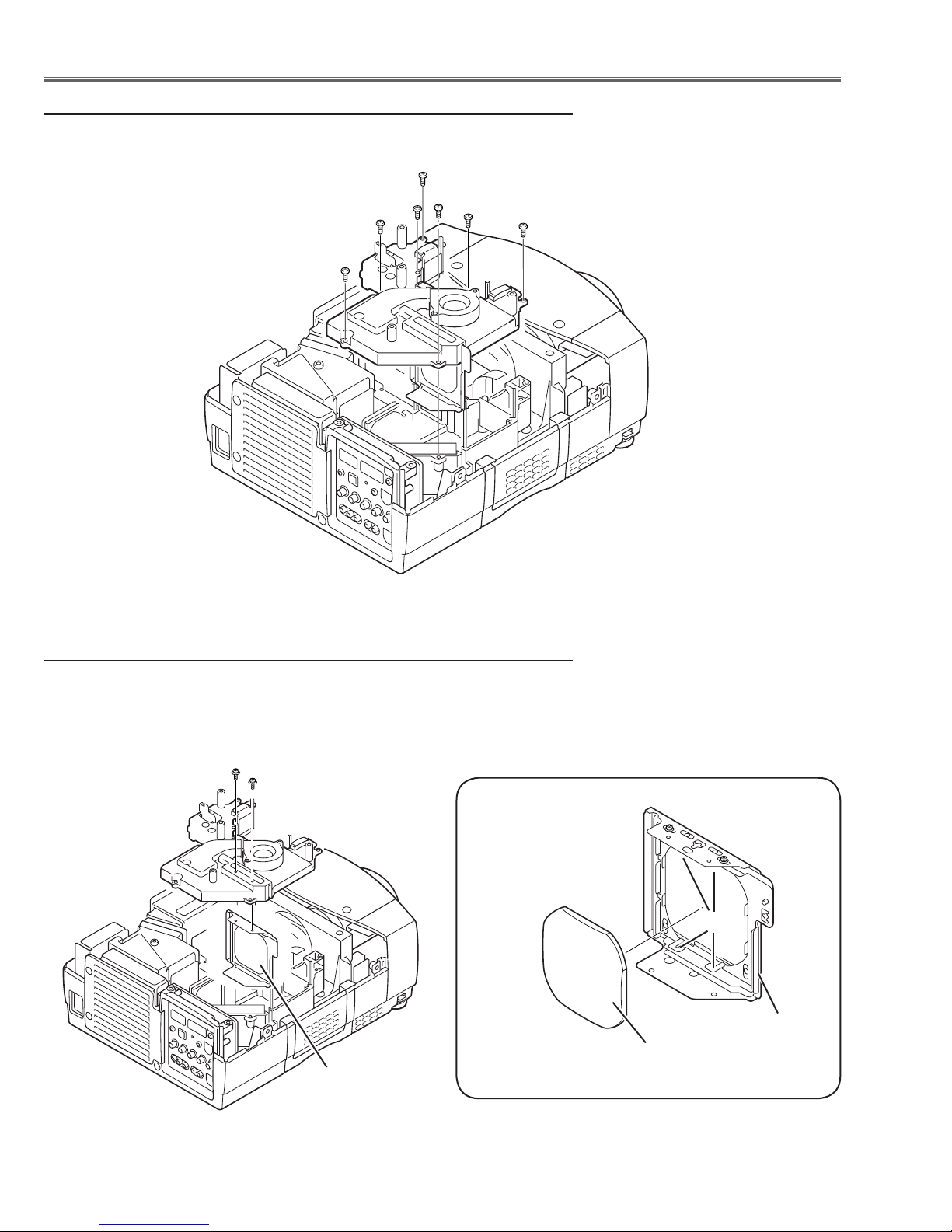
Optical Parts Disassemblies
Optical Unit Top removal
1 Remove 7 screws to take the Optical Unit Top off upward.
Condenser Lens disassembly
1 Remove 2 hex screws A and take the Condenser Lens ass’y.
2 Release 4 hooks B to take the Lens off from the holder.
A
A
Fig.5
* Lens should be placed
as the flat surface side
comes to the holder
side.
B
Condenser Lens
Holder
Condenser Lens
Fig.6-2
Fig.6-1
-16-
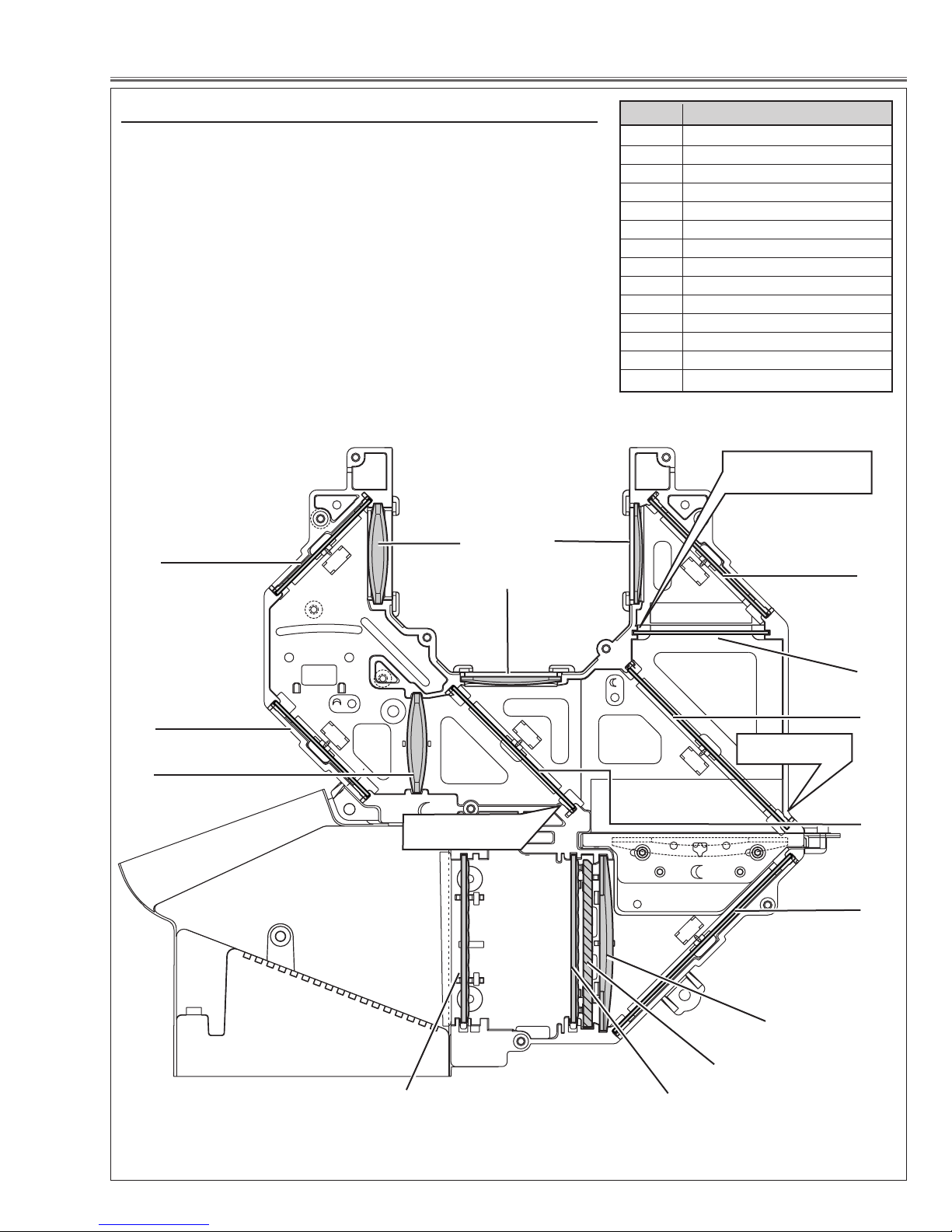
Optical Parts Disassemblies
Locations and Directions
When the optical parts in the optical unit mounting or assembling,
the parts must be mounted in the specified location and direction as
shown in figure below.
1
3
14
2
Key No. Description
1 Condenser lens (R)
2 Condenser lens
3 Condenser lens
4 Mirror (B)
5 Optical filter (UV cut)
6 Dichroic mirror (B
7 Dichroic mirror (G)
8 Mirror (W)
9 Condenser lens (IN)
10 PBS (prism beam splitter)
11 Integrator lens (OUT)
12 Integrator lens (IN)
13 Relay lens (IN)
14 Mirror (R)
The cutting corner
comes to this side up.
4
14
13
The printed marker
comes this side.
12
11
5
6
The printed marker
comes this side.
7
8
9
10
Fig.7
-17-
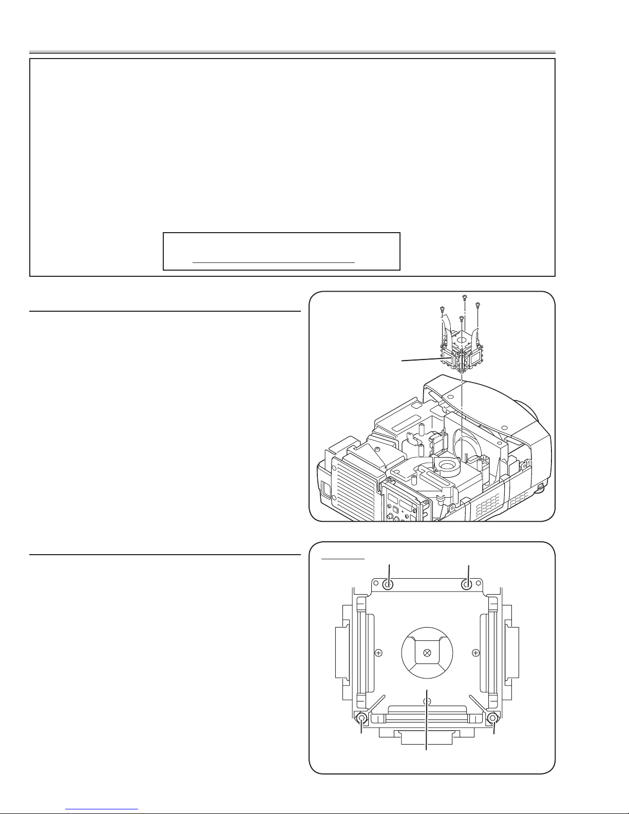
LCD Panel/Prism Ass’y Replacement
IMPORTANT NOTICE on LCD Panel/Prism Ass'y Replacement
LCD panels used for this model can not be replaced separately. Do not disassemble the LCD Panel/Prism Ass’y.
These LCD panels are installed with precision at the factory. When replacing the LCD panel, should be replaced
whole of the LCD panels and prism ass’y at once.
After replacing LCD Panel/Prism ass’y, please check the following adjustments.
- Check the “Condenser Lens Adjustment” and “Relay Lens Adjustment” following to chapter “Optical
Adjustment”.
- Check the “White Balance Adjustment” and “Common Centre Adjustment” following to chapter “Electrical
Adjustment”.
- Check the white uniformity on the screen.
If you find the color shading, please adjust the white uniformity by using the proper computer and “Color
Shading Correction” software supplied separately. The software can be ordered as follows;
COLOR SHADING CORRECTION Ver. 4.00
Service Parts No. 645 075 9611
LCD Panel/Prism Ass’y removal
1 Remove the cabinet top and main board following to
“Mechanical Disassemblies”.
2 Remove 4 screws by using the 2.0 mm hex driver and
take the LCD Panel/Prism ass’y off upward from the opti
cal unit.
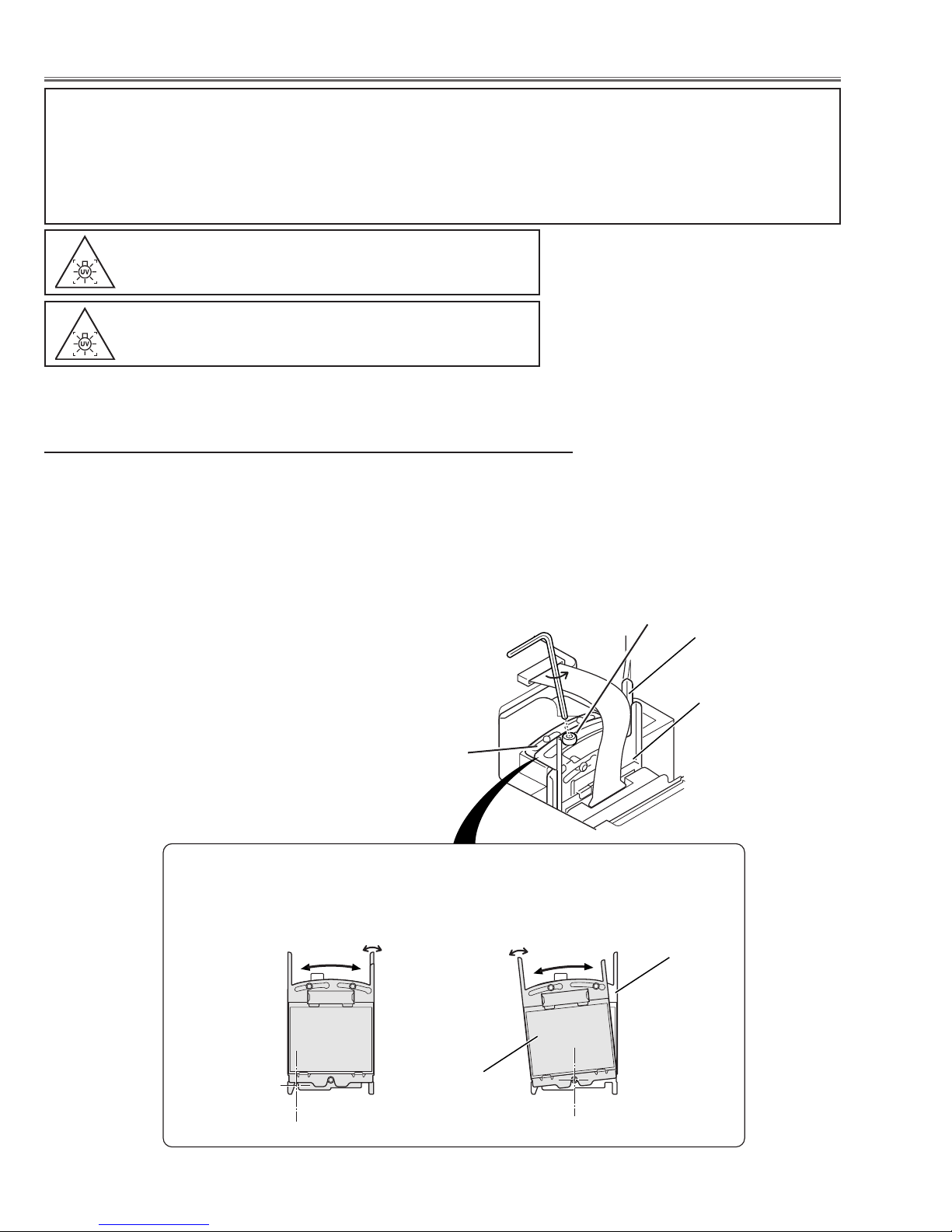
Note on LCD Panel/Prism Ass’y Mounting
After replacing or installing the LCD Panel/Prism ass'y,
please make sure to obtain the best focus in both TELE
and WIDE zoom. If the focus adjustment is required,
please adjust the positioning of LCD Panel/Prism Ass’y by
following the below procedure.
Note:
Do not replace the LCD
panel separately otherwise
it can not obtain proper
picture.
LCD Panel/Prism
Ass’y
Top View
A
A
Mounting Procedure:
1 Loosen 4 screws A on the LCD Panel/Prism ass'y with
2.0 mm hex driver.
2 Turn the projector on and project the image with WIDE
zoom, and adjust the FOCUS control to obtain the best
focus.
3 Turn the ZOOM control to the TELE position.
4 Move the LCD Panel/Prism Ass’y backward or for-
ward (about 0mm ~ 0.8mm) to obtain the proper focus.
Confirm the focus at TELE and WIDE zoom.
5 Tighten 4 screws A to fix the LCD Panel/Prism ass'y.
-18-
A
LCD Panel/Prism Ass’y
A

Adjustments
Turning On the Projector
If the PIN code is set on the projector, you cannot use the projector. The PIN code can be reset to the factory default
setting (1234) according to the following procedure.
When you reset the PIN code, the Logo PIN code and key lock will be reset, as well.
1. Disconnect the AC power cord from the AC outlet.
2. As pressing the SELECT button on the projector, connect the AC power cord into an AC outlet again. Keep
pressing the SELECT button until the POWER indicator lights continuously.
3. Turn the projector on with the ON-OFF button, enter the PIN code "1234" (the factory default setting).
Please refer to the owners manual for further information.
Adjustments after Parts Replacement
Cond enser le ns adj ustme nt
Mechan ical
adjustment
Relay len s a djust ment
R-Co ntrast a djust ment
G-Co ntrast a djust ment
B-Co ntrast a djust ment
Outp ut vo ltage ad justm ent
Fan output voltages ad ju stment
Vide o c enter adjus tment
Electrical adjust ment
NRS adj ustme nt
Referenc e vol tages ad justm ent
PC inpu t adju stmen t
AV In put ad ju stmen t
Comm on cente r adju stmen t
● : Adjustment necessary ❍ : Check necessary
Disa ss em bly/Re pl ac ed Par ts
LCD/ Pr is m
Ass' y
Cond en se r
Lens
❍ ●
❍ ●
● ●
Relay
Lens
Pol ar iz ed gl as s
R G B
●
●
Power
Board
●
●
Sub
Power
Board
● ●
Main
Board
●
●
●
●
●
PC gamm a shif t a djust ment
PC whit e bala nce adju stmen t
AV ga mma sh if t adju stmen t
AV wh ite ba la nce ad justm ent
● ●
❍ ❍
● ●
❍ ❍
-19-
Optical Adjustments
Optical Filter(WV)
Optical Filter(WV)
Polarized Glass
Polarized Glass
Before taking optical adjustments below, remove the Cabinet Top and Main Board following to the “Mechanical
Disassemblies”
Adjustments require a 2.0mm hex wrench and a slot screwdriver.
Note: Do not disconnect connectors K8L, K8X, K8D, K8G and K8E on the main board, because the projector can
not turn on due to operate the power failure protection.
WARNING : USE UV RADIATION EYE AND SKIN
PROTECTION DURING SERVICING.
CAUTION:
To prevent suffer of UV radiation, those adjustments
must be completed within 25 minutes.
[Before Adjustment]
- Input a 100% of black raster signal.
Contrast adjustment
1 Loosen a screw A (Fig.1-1/1-4) on the polarized glass mount-
ing base which you intend to adjust.
2 Turn the polarized glass mounting base with knob B as shown
in Fig.1-2 to obtain the darkest brightness on the screen. (The
polarized glass and optical filter move together.)
3 Turn the optical filter mounting base with know C as shown
in Fig.1-3 to obtain the black color uniformity on the
screen.(Move only the optical filter.)
4 Tighten the screw A to fix the polarized glass mounting base.
A
Repeat steps 1 to 4 for remaining R, G or B contrast adjustment.
Polarized glass
mounting base
B
Fig.1-1
C
Fig.1-2
Fig.1-3
-20-
Optical Adjustments
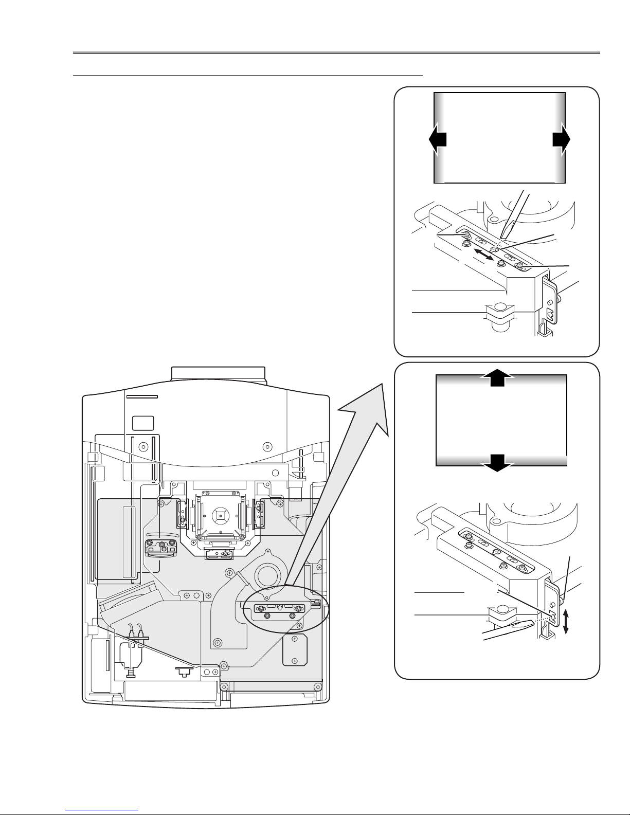
Condenser Lens adjustment
1 Turn the projector on by a state of without FPC cables.
2 Adjust the adjustment base of condenser lens ass’y to make color
uniformity in white.
1) If the shading appears on the left or right of the screen as
shown in Fig.2-1, loosen 2 screws A with the 2.0mm hex driver, and adjust the slot B to make color uniformity in green by
using a slot screwdriver.
2) If the shading appears on the top or bottom of the screen as
shown in
and adjust the slot D to make color uniformity in green by
using a slot screwdriver
Fig.2-2, loosen 1 screw C with the 2.0mm hex driver,
3 Tighten screws A and C to fix the Condenser lens unit.
Note:
The relay lens adjustment must be carried out after completing this
adjustment.
A
a
Fig.2-1
Moving of slot B
White
b
Slot B
A
Slot D
Fig.2-2
Moving of Slot D
White
C
x
y
-21-
Optical Adjustments
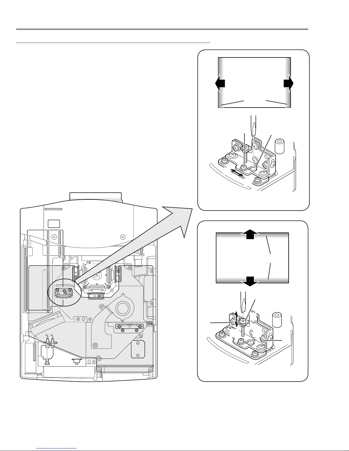
Relay lens-Out adjustment
1 Turn the projector on by a state of without FPC cables.
2 Adjust the adjustment base of relay lens ass’y to make color
uniformity in white.
1) If the cyan bar appears on the left or right of the screen as
shown in Fig.4-1, loosen 1 screw A with the 2.0mm hex driver,
and adjust the slot B to make color uniformity in white by using
a slot screwdriver.
2) If the cyan bar appears on the top or bottom of the screen as
shown in
and adjust the screw D to make color uniformity in white by
using a slot screwdriver.
Fig.4-2, loosen 2 screws C with the 2.0mm hex driver,
3 Tighten the screws A and C to fix the relay lens unit.
a
a
White
Cyan
A
b
b
Slot B
Fig.4-1
Moving of slot B
x
C
y
x
White
y
Screw D
x
Cyan
y
C
Fig.4-2
Moving of slot D
-22-
Service Mode
Input Input 1
Group No. Data
0 0 32
Ver. R 1.00
Electrical Adjustments
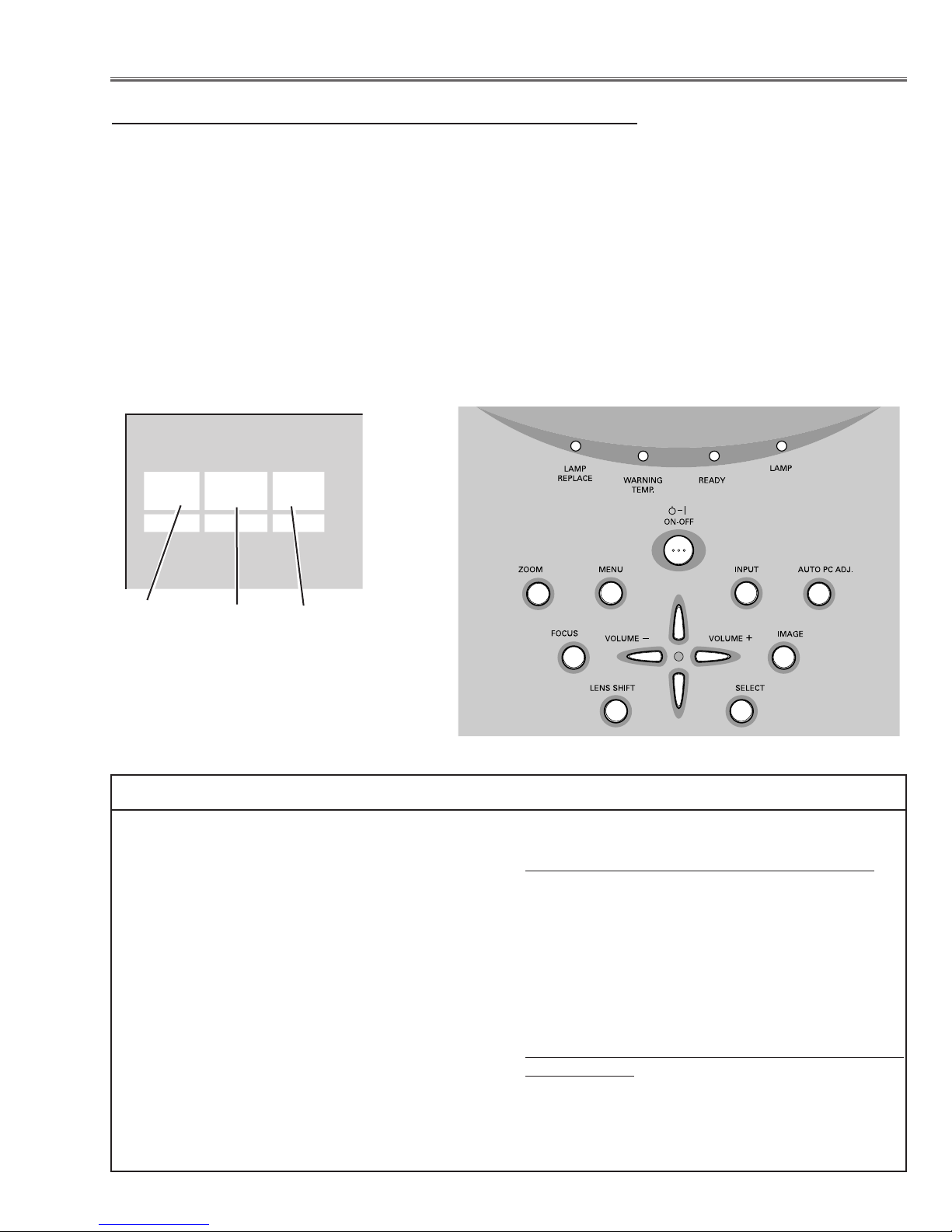
Service Adjustment Menu Operation
To enter the service mode
To enter the “Service Mode”, press and hold the MENU and IMAGE button on the projector at the same time for
more than 3 seconds. The service menu appears on the screen as follows.
To adjust service data
Select the adjustment group no. by pressing the SELECT(increase) or MENU (decrease) button, and select
the adjustment item no. by pressing the pointer UP or DOWN button, and change the data value by pressing the
VOLUME – or VOLUME + button. Refer to the “Service Adjustment Data Table” for further description of adjustment group no., item no. and data value.
To exit the service mode
To exit the service mode, press the POWER ON-OFF button on the projector or remote control unit.
Group No.
Memory IC Replacement (IC802)
The memory IC on the main board stores the data for
the service adjustments, and should not be replaced
except for the case of defective device.
If replaced, it should be performed the re-adjustments
following to the “Electrical Adjustments”.
The data of lamp replacement monitor timer is stored
in the memory IC.
Please note that the lamp replace counter is reset
when the memory IC is replaced.
(Lamp replace counter can not be set to the previous
value.)
● Caution to memory IC replacement
When the memory IC is replaced with new one, the
CPU writes down the default data of the service
adjustments to the replaced IC, refer to the service
adjustment table. As these data are not the same
data as factory shipped data, it should be required to
Item No.
Data value
perform the re-adjustments following to the “Electrical
Adjustments”.
Please note that the lamp replace counter is reset.
● Caution of Main Board replacement (in case of
the memory IC is not defective)
When the main board is replaced, the memory IC
should be replaced with the one on previous main
board. After replacement, it should be required to
perform the re-adjustments following to the “Electrical
Adjustments”.
In this case, the lamp replace counter can be kept the
value as before.
-23-
Electrical Adjustments
White 100%
Black 100%
Circuit Adjustments
CAUTION: The each circuit has been made by the fine adjustment at factory. Do not attempt to adjust the follow-
ing adjustments except requiring the readjustments in servicing otherwise it may cause loss of performance and product safety.
WARNING : USE UV RADIATION EYE AND SKIN
PROTECTION DURING SERVICING.
CAUTION:
To prevent suffer of UV radiation, those adjustments
must be completed within 25 minutes.
[Adjustment Condition]
● Input signal
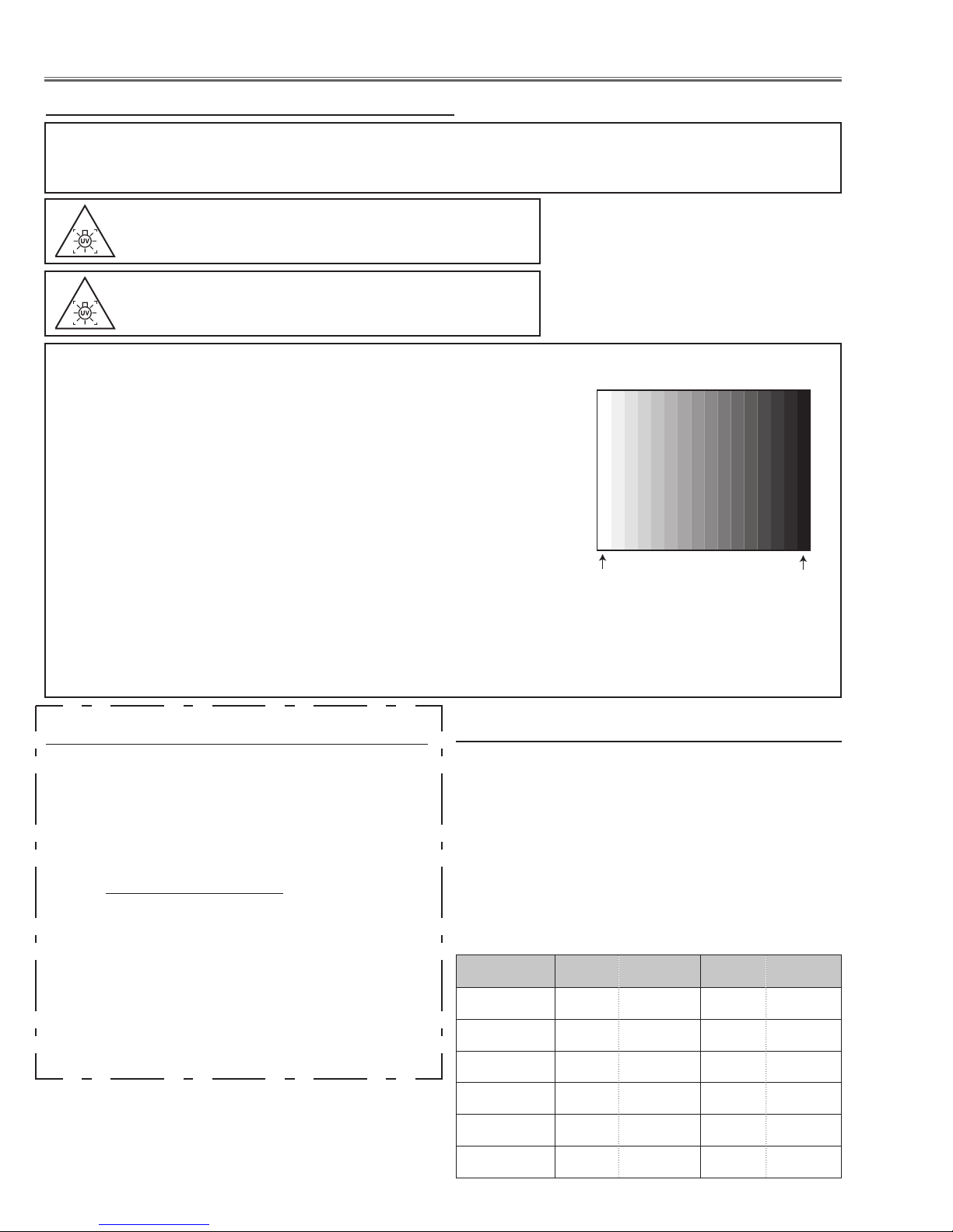
Video signal .......................... 1.0Vp-p/75Ω terminated, 16 steps gray
scale, white 100% and black 0% pattern (Composite video signal)
Computer signal .................... 0.7Vp-p/75Ω terminated, 16 steps gray
scale pattern (WXGA)
Component Video signal ....... 0.7Vp-p/75Ω terminated, 16 steps gray
scale, white 100% and black 0% pattern (480i format)
RGB Video signal .................. 0.7Vp-p/75Ω terminated, 16 steps gray
scale, white 100% and black 0% pattern (480p format)
● Picture control mode ............... “STANDARD” mode unless otherwise noted.
Note:
* Please refer to “Service Adjustment Menu Operation” for entering to the service mode and adjusting the service
data.
z Output Voltage adjustment
After replacing the Power Board readjust the Output
voltage adjustment as follows.
1. Connect a digital voltmeter to pins 1 (+) and 3 (-) of
K6A.
2. Adjust the voltage by using VR601 as following.
AC Input Reading
230V 370V ±2V
* This adjustment is not required even if the power
Caution:
board is replaced because this adjustment is carried
Be sure to connect the lamp when taking this adjust-
out before parts shipment.
ment.
x Fan Voltages adjustment
1. Enter the service mode.
2. Connect a digital voltmeter to test point
chassis ground (-). (6 test points are provided for this
adjustment, perform all the voltage adjustments in
the table below.)
3. Select group no. “
data value to adjust the voltage to be C ±0.05V, and
select item no. D and change data value to adjust
the voltage to be E ±0.05V.
4. Repeat step 2 to 3 for the remaining test points in
the table below.
Test Point A Item B Voltage C Item D Voltage E
TPFN3 0 14.0 1 6.5
16 steps gray scale pattern
A (+) and
140”. Select item no. B and change
TPFN7 2 14.0 3 5.0
TPFN6 4 14.0 5 5.0
TPFN4 6 14.0 7 5.0
FAN1
FAN2
-24-
8 14.0 9 5.0
10 14.0 11 5.0

Electrical Adjustments
(a)
White Level
c Video Center adjustment
1. Receive the 16-step gray scale computer signal with
Input 1 [RGB(Analog)] mode.
2. Enter the service mode.
3. Connect a digital voltmeter to test point “
and chassis ground (-).
4. Select group no. “
value to adjust the voltage to be 7.0 ±0.05Vdc.
5. Connect a digital voltmeter to test point “TPV1R” (+)
and chassis ground (-).
6. Select item no. “
the voltage to be 7.0 ±0.05Vdc.
7. Connect a digital voltmeter to test point “TPV1B” (+)
and chassis ground (-).
8. Select item no. “
the voltage to be 7.0 ±0.05Vdc.
200”, item no. “0” and change data
1” and change data value to adjust
2” and change data value to adjust
TPV1G” (+)
v NRS adjustment
1. Receive the 16-step gray scale computer signal with
Input 1 [RGB(Analog)] mode.
2. Enter the service mode.
3. Connect a digital voltmeter to test point “
and chassis ground (-).
4. Select group no. “
value to adjust the voltage to be 2.5 ±0.05Vdc.
5. Connect a digital voltmeter to test point “TPNRSB” (+)
and chassis ground (-).
6. Select item no. “
the voltage to be 7.5 ±0.05Vdc.
200”, item no. “3” and change data
4” and change data value to adjust
TPNRSA” (+)
b Reference Voltages adjustment
1. Receive the 16-step gray scale computer signal with
Input 1 [RGB(Analog)] mode.
2. Enter the service mode.
3. Connect a digital voltmeter to test point “
(+) and chassis ground (-).
4. Select group no. “
value to adjust the voltage to be 9.38 ±0.05Vdc.
5. Connect a digital voltmeter to test point “TPREG_R”
(+) and chassis ground (-).
6. Select item no. “
the voltage to be 9.38 ±0.05Vdc.
7. Connect a digital voltmeter to test point “TPREF_B”
(+) and chassis ground (-).
8. Select item no. “
the voltage to be 9.38 ±0.05Vdc.
200”, item no. “6” and change data
7” and change data value to adjust
8” and change data value to adjust
TPREF_G”
n PC Input adjustment
1. Receive the 16-step gray scale computer signal with
Input 1 [RGB(Analog)] mode.
2. Enter the service mode.
3. Select group no. “
value from 0 to 1. The projector starts self-adjust
ment. When the adjustment completes correctry,
"OK" will appear on the screen. If "NG" appears, try
adjustment again.
680”, item no. “0” and change data
m A/V Input adjustment
1. Receive the 16-step grey scale comosite video signal
with Input 3 [Video] mode.
2. Enter the service mode.
3. Connect an oscilloscope to test point “
and chassis ground (-).
4. Select group no. “
amplitude “a” to be minimum by changing the Data
value.
5. Receive the 16-step grey scale component video
signal (Y/Cb/Cr 480p) with Input 3 [Y,Pb/Cb,Pr/Cr]
mode.
6. Select group no. “
amplitude “a” to be minimum by changing the Data
value.
7. Receive the 16-step grey scale component video sig
nal (Y/Pb/Pr 1080i-60) with Input 3 [Y,Pb/Cb,Pr/Cr]
mode.
8. Select item no. “
300”, item no. “2” and adjust the
300”, item no. “0” and adjust the
0” and adjust the amplitude “a” to be
minimum by changing the Data value.
9. Receive the 16-step grey scale component video sig
nal (Y/Pb/Pr 720p-60) with Input 3 [Y,Pb/Cb,Pr/Cr]
mode.
10. Select item no. “
be minimum by changing the Data value.
11. Receive the 16-step grey scale component video sig
nal (Y/Pb/Pr 720p-60) with Input 3 [Y,Pb/Cb,Pr/Cr]
mode.
12. Select item no. “
be minimum by changing the Data value.
0” and adjust the amplitude “a” to
0” and adjust the amplitude “a” to
TP35G” (+)
-
-
-
-
-25-

Electrical Adjustments
, Common Center adjustment
1. Receive the 1 line black/white pattern computer signal with Input 1 [RGB(Analog)] mode.
2. Enter the service mode.
3. Project only green light component to the screen.
4. Select group no. “
data value to obtain the minimum flicker on the
screen.
5. Project only red light component to the screen.
6. Select item no. “
the minimum flicker on the screen.
7. Project only blue light component to the screen.
8. Select item no. “
the minimum flicker on the screen.
200”, item no. “18” and change
19” and change data value to obtain
20 and change data value to obtain
. PC Gamma-shift adjustment
1. Receive the 100%whole-white computer signal with
Input 1 [RGB(Analog)] mode.
2. Enter the service mode.
3. Measure luminance on the screen with the luminance
meter. It is A for the reading of luminance meter.
4. Change the signal source to the 50%whole-white
computer signal with Input 1 [RGB(Analog)] mode.
5. Select group no. “
Data value to make the reading of luminance meter
A x 19%.
to be
200”, Item no. “27” and change the
⁄1 AV Gamma-shift adjustment
1. Receive the 100%whole-white component video signal (Y/Cb/Cr) with Input 3 [Y,Pb/Cb,Pr/Cr] mode.
2. Enter the service mode.
3. Measure luminance on the screen with the luminance
meter. It is
4. Change the signal source to the 50%whole-white
computer signal with Input 3 [Y,Pb/Cb,Pr/Cr] mode.
5. Select group no. “
Data value to make the reading of luminance meter
to be
A for the reading of luminance meter.
210”, Item no. “27” and change the
A x 19%.
⁄2 PC White Balance adjustment
1. Receive the 100%whole-white component video signal (Y/Cb/Cr) with Input 3 [Y,Pb/Cb,Pr/Cr] mode.
2. Enter the service mode, select group no. “210”, item
no. “28” (Red) or “29” (Blue), and change data values respectively to make a proper white balance.
Confirm that the same white balance is obtained in
video and computer input.
⁄0 PC White Balance adjustment
1. Receive the 50%whole-white computer signal with
Input 1 [RGB(Analog)] mode.
2. Enter the service mode, select group no. “
no. “28” (Red) or “29” (Blue), and change data values respectively to make a proper white balance.
Confirm that the same white balance is obtained in
video and computer input.
200”, item
NOTE ON WHITE UNIFORMITY
ADJUSTMENT
If you find the color shading on the screen, please
adjust the white uniformity by using the proper computer and “Color Shading Correction” software supplied
separately. The software can be ordered as follows;
COLOR SHADING CORRECTION Ver. 4.00
Service Parts No. 645 075 9611
-26-
Electrical Adjustments
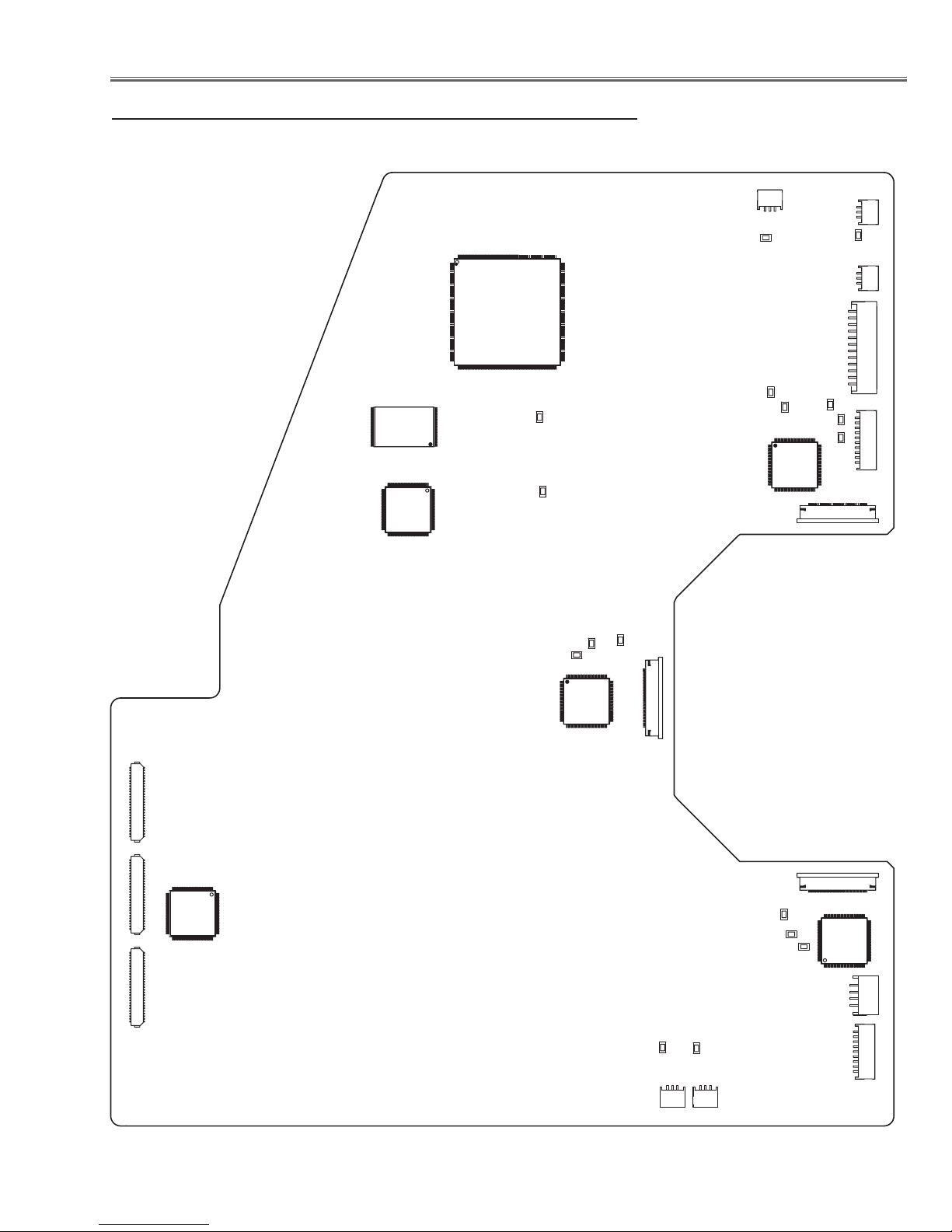
K10A
K10B
K10C
IC561
TPV1B
TPV1G
TPREF_G
TPV1R
TPNRSA
TPNRS
B
FAN1
FAN2
K8D
K8E
K35B
K8J
K8L
K8M
TP35B
K8N
K35G
K8O
K8
P
TP35G
K8S
K35R
TP35R
IC801
IC1811
IC4701
TPFN3
TPFN4
TPFN6
TPFN7
IC501
IC8201
IC531
TPREF_R
TPREF_B
Test Points and Locations
● MAIN BOARD
-27-
Electrical Adjustments
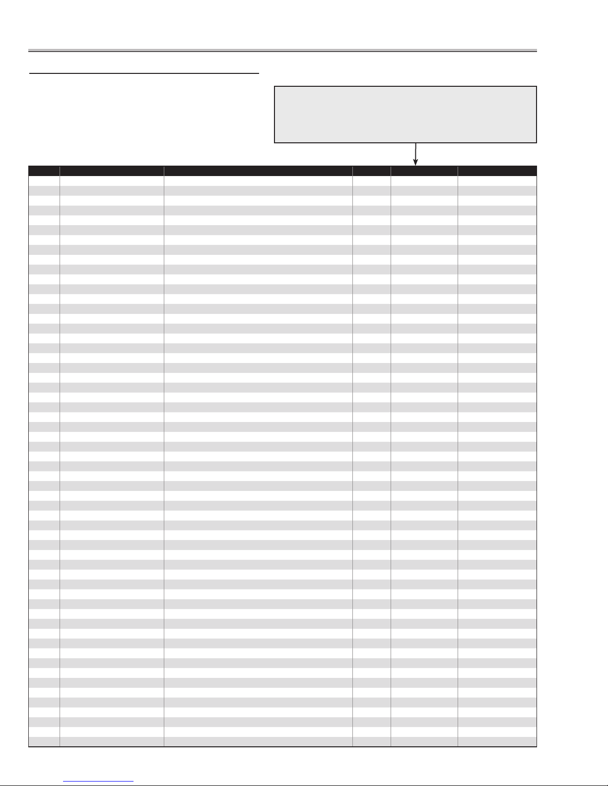
Service Adjustment Data Table
These initial values are the reference data written from the
CPU ROM to memory IC when replaced new memory IC. The
adjustment items indicated with “
lowing to the “Electrical adjustments”. Other items should be
used with the initial data value.
Group
No. Item Function Range Initial Value
0 Thermal Monitor Read only
0 LM76(Temp) A Monitor Sensor A for External IC1691 - -
1 LM76(Temp) B Monitor Sensor B for Lamp IC1816 - -
2 LM76(Temp) C Monitor Sensor C for Panel IC1814 - -
1 Atmosphere Monitor Read only
0 MPXA4114A(Pressure) Monitor Atmosphere sensor - -
1 MPXA4114A(Pressure) Monitor Atmosphere sensor [unit: mmHg] - -
2 MPXA4114A(Pressure) Monitor Atmosphere sensor [unit:hpa] - -
✻” are required to readjust fol-
5 FAN A Monitor (PBS) Current voltage of Fan (0.01V unit)
FAN B Monitor (Lamp-IN) Current voltage of Fan (0.01V unit)
FAN C Monitor (Lamp-Front) Current voltage of Fan (0.01V unit)
FAN D Monitor (Power) Current voltage of Fan (0.01V unit) - -
FAN E Monitor (Panel) Current voltage of Fan (0.01V unit)
FAN F Monitor (Exhust) Current voltage of Fan (0.01V unit) - -
10 RS232C Setting * Do not change setting when using LAN card
0 Reset Disable PJ-Net Reset (0:Enable / 1:Disable) 0 / 1 0
11 PJ-Net Setting
0 LAN Card Switch LAN (0: Disable / 1: Enable) 0 / 1 0
20 Logo prohibition
0 Logo prohibition Logo prohibition(0: Menu / 1: Forced) 0 / 1 0
30 Color Shading/Gamma
0 Color Shading Correction On/Off Color Shading Correction (0:Off / 1:On) 0 / 1 1 Not memorized
1 Gamma Correction On/Off Gamma Correction (0:Off / 1:On) 0 / 1 1 Not memorized
40 Dimmer Control
0 Dimmer Level 0:250 ~ 15:300W Effect only 300W 0 ~ 15 15
2 DIMMER CTRL LEVEL1 Bright level1 data: Bright level1 when less than the value 0 ~ 255 7
3 DIMMER CTRL LEVEL2 Bright level2 data: Bright level2 when less than the value 0 ~ 255 14
4 DIMMER CTRL LEVEL3 Bright level3 data: Bright level3 when less than the value 0 ~ 255 21
5 DIMMER CTRL LEVEL4 Bright level4 data: Bright level4 when less than the value 0 ~ 255 28
6 DIMMER CTRL LEVEL5 Bright level5 data: Bright level5 when less than the value 0 ~ 255 35
7 DIMMER CTRL LEVEL6 Bright level6 data: Bright level6 when less than the value 0 ~ 255 42
8 DIMMER CTRL LEVEL7 Bright level7 data: Bright level7 when less than the value 0 ~ 255 49
9 DIMMER CTRL LEVEL8 Bright level8 data: Bright level8 when less than the value 0 ~ 255 56
10 DIMMER CTRL LEVEL9 Bright level9 data: Bright level9 when less than the value 0 ~ 255 63
11 DIMMER CTRL LEVEL10 Bright level10 data: Bright level10 when less than the value 0 ~ 255 70
12 DIMMER CTRL LEVEL11 Bright level11 data: Bright level11 when less than the value 0 ~ 255 77
13 DIMMER CTRL LEVEL12 Bright level12 data: Bright level12 when less than the value 0 ~ 255 84
14 DIMMER CTRL LEVEL13 Bright level13 data: Bright level13 when less than the value 0 ~ 255 91
15 DIMMER CTRL LEVEL14 Bright level14 data: Bright level14 when less than the value 0 ~ 255 98
16 DIMMER CTRL LEVEL15 Bright level15 data: Bright level15 when less than the value 0 ~ 255 105
17 DIMMER AVE POINT Average point data for dimmer 1~16 4
- -
- -
- -
50 Auto-Picture Control
0 Auto-Picture Control Forced OFF 0:follows to Menu, 1:Forced OFF 0 / 1 0
70 COOLING
0 COOLING_TIME Cooling time period after power off 10-120 90
1 Not used -1
80 Projector Use time
0 PJ Time Reset It resets the time when the value is changes to 10. 0 ~ 10 0
-28-
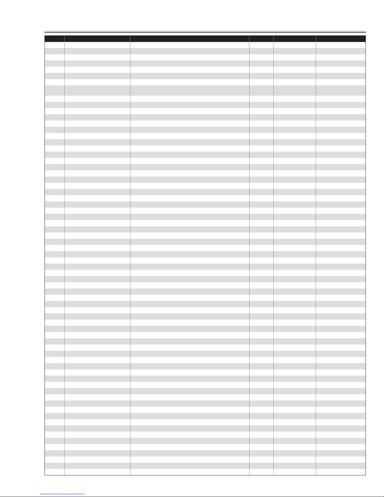
Electrical Adjustments
Group
No. Item Function Range Initial Value
90 Operation History
0 OPERATION_HISTORY_1 Operation history in last operation 0~32767 0
~
49 OPERATION_HISTORY_50 Operation history last 50th operation 0~32767 0
50 OPERATION_HISTORY Reset It resets the history when the value is changed to 10. 0 ~ 10 0
91 Projector Failure History
0 Warning Log 1 Latest Failure log 0 ~ 32767 0
~
49 Warning Log 50 50th Failure log 0 ~ 32767 0
50 Warning Log Reset It resets the Log when the value is changed to 10. 0 ~ 10 0
112 Lamp Config
0 Lamp Config Change Lamp life selection (Step : 500h) 1000 ~8000 2000/1500
113 Lamp Reset Counter (Read only)
0 Lamp Reset Counter Reset times of the Lamp time counter 0 ~127 0
115 Kamp Go Out
0 Lamp Go Out 0: Disable / 1: Enable 0 / 1 0
116 Lamp Replace Display
0 Display when Lamp Replace time 0: Disable / 1: Enable 0 / 1 0
120 RC KEY Disable
1 RC KEY Front/Rear Disable 0:Enable / 1:Front RC Disable / 2:Rear RC Disable / 3:RC KEY All Disable 0 ~ 3 0
130 75 ohm terminated
0 TERM_1 Input1(D SUB) terminated (0: OFF / 1: ON) 0 / 1 0
1 TERM_2 Input2(BNC) terminated (0: OFF / 1: ON) 0 / 1 0
140 Fan Control
0 Fan A Max (DAC) 0 ~ 255
1 Fan A Min (DAC) 0 ~ 255
2 Fan B Max (DAC) 0 ~ 255
3 Fan B Min (DAC) 0 ~ 255
4 Fan C Max (DAC) 0 ~ 255
5 Fan C Min (DAC) 0 ~ 255
6 Fan D Max (DAC) 0 ~ 255
7 Fan D Min (DAC) 0 ~ 255
8 Fan E Max (DAC) 0 ~ 255
9 Fan E Min (DAC) 0 ~ 255
10 Fan F Max (DAC) 0 ~ 255
11 Fan F Min (DAC) 0 ~ 255
* See "Power Falure Error His
tory"
-
141 Fan Optiion
0 Hi-Land SW 0:Normal Mode1: High-land Mode (Fan max speed continuously) 0 ~ 1 0
1 Not used Not used --
142 Fan Temp Error Setting Read only 300W
0 Temp A Warning Temp A to judge the temp error (x10) 0 ~ 1000 460
1 Temp B Warning Temp B to judge the temp error (x10) 0 ~ 1000 800
2 Temp C Warning Temp C to judge the temp error (x10) 300 ~ 1000 590
3 Temp B-A Warning Temp B-A to judge the temp error (x10) 0 ~ 1000 500
4 Temp C-A Warning Temp C-A to judge the temp error (x10) 0 ~ 1000 270
143 Fan Manual Control for factory exam
144 Fan Table Settingl for factory exam
145 Fan Offset Setting for factory exam
146 Fan Start Setting for factory exam
147 Fan Air pressure Setting for factory exam
148 Fan Ceiling Setting for factory exam
-29-
Electrical Adjustments
Group
No. Item Function Range Initial Value
149 Fan cloggle Setting for factory exam
150 Shippment Setting
0 Shippment Setting All of settings are set to default when the value changes to 10 0 ~ 10 0
160 not used
180 DDC Setting
0 HDCP EDID Data Setting 0:EDID Data for DVI / 1:EDID Data for HDCP 0 / 1 1
200 Panel Adjustment PC [Lamp ALL]
0 G_V1 (A02) DAC G Video center Adj. 0 ~ 255 127
1 R_V1 (A01) DAC R Video center Adj. 0 ~ 255 127
2 B_V1 (A03) DAC B Video center Adj. 0 ~ 255 127
3 NRSA (A04) DAC NRSA Adj. 0 ~ 255 118
4 NRSB (A05) DAC NRSB Adj. 0 ~ 255 125
5 Not used Not used
6 G_VREF (A07) DAC G Reference Voltage Adj. 0 ~ 255 114
7 R_VREF (A06) DAC R Reference Voltage Adj. 0 ~ 255 114
8 B_VREF (A08) DAC B Reference Voltage Adj. 0 ~ 255 114
9 Not used Not used
10 Not used Not used
11 Not used Not used
12 Not used Not used
13 Not used Not used
14 Not used Not used
15 G CONTRAST (Digital Gamma) PC/DIGITAL G [501h] 0 ~ 4096 2048
16 R CONTRAST (Digital Gamma) PC/DIGITAL R [101h] 0 ~ 4096 2048
17 B CONTRAST (Digital Gamma) PC/DIGITAL B [901h] 0 ~ 4096 2048
18 G_LCCOM (L3E06110) G Common Center Adj. 0 ~ 255 119
19 R_LCCOM (L3E06110) R Common Center Adj. 0 ~ 255 119
20 B_LCCOM (L3E06110) B Common Center Adj. 0 ~ 255 119
21 Not used Not used - -
22 Not used Not used - -
23 Not used Not used - -
24 Not used Not used - -
25 Not used Not used - -
26 Not used Not used - -
27 G GAMMA SHIFT Differetial PC 50% Gamma Adj. G [503h] Link with RB -2048 ~ 2047 0
28 R GAMMA SHIFT Differetial PC 50% Gamma Adj. R [103h] -2048 ~ 2047 0
29 B GAMMA SHIFT Differetial PC 50% Gamma Adj. B [903h] -2048 ~ 2047 0
210 Adjustment AV
0 (Not Used) (Not Used) -
1 (Not Used) (Not Used) -
2 (Not Used) (Not Used) -
3 (Not Used) (Not Used) -
4 (Not Used) (Not Used) -
5 (Not Used) (Not Used) -
6 (Not Used) (Not Used) -
7 (Not Used) (Not Used) -
8 (Not Used) (Not Used) -
9 (Not Used) (Not Used) -
10 (Not Used) (Not Used) -
11 (Not Used) (Not Used) -
12 (Not Used) (Not Used) -
13 (Not Used) (Not Used) -
14 (Not Used) (Not Used) -
15 G CONTRAST AV/DIGITAL(HDCP) 0 ~ 4096 2048
16 R CONTRAST AV/DIGITAL(HDCP) 0 ~ 4096 2048
17 B CONTRAST AV/DIGITAL(HDCP) 0 ~ 4096 2048
18 (Not Used) (Not Used) -
19 (Not Used) (Not Used) -
20 (Not Used) (Not Used) -
21 G GAMMA SHIFT AV 50% Luminance Ratio AdjsutmentG Gamma Shift[503h] -2048 ~ 2047 0
22 R GAMMA SHIFT AV 50% Luminance Ratio AdjsutmentR Gamma Shift[103h] -2048 ~ 2047 0
23 B GAMMA SHIFT AV 50% Luminance Ratio AdjsutmentB Gamma Shift[903h] -2048 ~ 2047 0
24 G Gain Coefficient AV G Gain Coeficent adjustment [501h] 0 ~ 255 0
25 R Gain Coefficient AV R Gain Coeficent adjustment [101h] 0 ~ 255 0
-30-
 Loading...