

Sanyo PLV-70,PLV-70L Service Manual
Notice
CORRECTION
SERVICE FLASH ADD INFORMATION
PRODUCTION CHANGE
●
FILE NO.
REVISION-5
Please add this notice to the Service Manual listed below.
Category : Multi-media Projector Issued Date : July / 2005
PLV-70 M4L-7004
Model : PLV-70L Effective from : Chassis No. M4L-70L01
Canada, U.S./Europe,
Destination : Asia, Africa, U.K. REF. NO. : SM5110361
NOTE: Match the Chassis No. on the unit’s back cover with the Chassis No. in the Service
Manual.
If the Chassis. No. does not match the unit’s, additional service literature is required.
Only the difference service information is given in this manual. For detailed service
information, refer to the original service manual and notice for Models PLV-70, PLV-70L.
Reason of the production change:
As this production change is to comply with RoHS, PWB units and some parts are changed.
Major chaged parts are as follows;
PWB BOARD
Main Board
A/V Board
I/F Board
Control Baord
RC Front Baord
Connect Board
Senser1 Board
FILE WITH ORIGINAL SERVICE MANUAL
SM5110361 for PLV-70
SS5110737 for PLV-70L
PRODUCT CODE
PLV-70 PLV-70L
1 122 130 60 1 122 130 70
1 122 131 60 1 122 131 70
1 122 131 62
REFERENCE NO. SM5110361-05

■ Contents
Contents ____________________________________________________ 2
Safety Instructions ____________________________________________ 3
Specifications ________________________________________________ 4
Adjustments after Parts Replacement _____________________________ 5
Circuit Protections ____________________________________________ 6
Fuse _______________________________________________________ 6
Thermal switch _______________________________________________ 6
Interlock switch _______________________________________________ 6
Warning temperature and power failure protection ___________________ 7
Mechanical Disassemblies ______________________________________ 8
Optical Parts Disassemblies ____________________________________ 13
LCD Panel/Prism Ass’y Replacement ____________________________ 18
Lamp Replacement __________________________________________ 19
Optical Adjustments __________________________________________ 20
Electrical Adjustments ________________________________________ 23
Service Adjustment Menu Operation _____________________________ 23
Circuit Adjustments ___________________________________________ 24
Test Points and Locations ______________________________________ 29
Service Adjustment Data Table _________________________________ 30
Electrical Parts List ___________________________________________ 44
Mechanical Parts List _________________________________________ 67
Optical Parts List ____________________________________________ 70
-2-
■ Safety Instructions
SAFETY PRECAUTIONS
WARNING:
The chassis of this projector is isolated (COLD) from AC line by using the converter transformer. Primary side
of the converter and lamp power supply unit circuit is connected to the AC line and it is hot, which hot circuit
is identified with the line (
personnel injury, servicing should be made with qualified personnel.
The following precautions must be observed.
) in the schematic diagram. For continued product safety and protection of
1: An isolation transformer should be connected in the
power line between the projector and the AC line
before any service is performed on the projector.
2: Comply with all caution and safety-related notes
provided on the cabinet back, cabinet bottom, inside
the cabinet or on the chassis.
3: When replacing a chassis in the cabinet, always be
certain that all the protective devices are installed
properly, such as, control knobs, adjustment
covers or shields, barriers, etc.
DO NOT OPERATE THIS PROJECTOR WITHOUT T
HE PROTECTIVE SHIELD IN POSITION AND PROP
ERLY SECURED.
4: Before replacing the cabinet cover, thoroughly
inspect the inside of the cabinet to see that no
stray parts or tools have been left inside.
Before returning any projector to the customer, the
service personnel must be sure it is completely safe
to operate without danger of electric shock.
PRODUCT SAFETY NOTICE
Product safety should be considered when a component replacement is made in any area of the projector.
Components indicated by mark ! in the parts list and the schematic diagram designate components in which
safety can be of special significance. It is, therefore, particularly recommended that the replacement of there
parts must be made by exactly the same parts.
Eye damage may result from directly viewing the light produced by the Lamp used in this equipment. Always
turn off Lamp before opening cover. The Ultraviolet radiation eye protection required during this servicing.
Never turn the power on without the lamp to avoid electric-shock or damage of the devices since the stabilizer
generates high voltages(15kV - 25kV) at its starts.
Since the lamp is very high temperature during units operation replacement of the lamp should be done at least
45 minutes after the power has been turned off, to allow the lamp cool-off.
SERVICE PERSONNEL WARNING
-3-
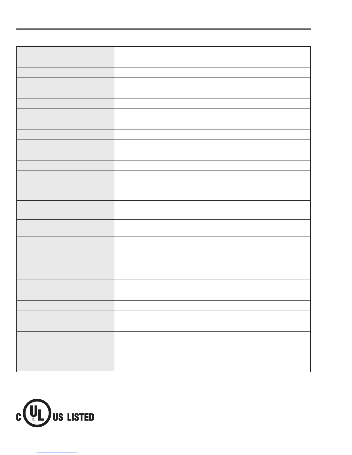
■ Specifications
Projector Type Multi-media Projector
Dimensions (W x H x D) 12.6” x 6.6” x 16.8” (319mm x 168mm x 429.5mm)
Net Weight 17.4 lbs (7.9 kg) PLV-70, 17.1 lbs (7.1 kg) PLV-70L
LCD Panel System 1.21” TFT Active Matrix type, 3 panels
Panel Resolution 1366 x 768 dots
Number of Pixels 3,147,264 (1366 x 768 x 3 panels)
Color System 6 color system (PAL, SECAM, NTSC, NTSC4.43, PAL-M and PAL-N)
High Definition TV SIgnals 480i, 480p, 575i, 575p, 720p. 1035i and 1080i
Scanning Frequency H-sync. 15 ~ 100kHz, V-sync. 50 ~ 100Hz
Projection Image Size (diagonal) Adjustable from 31” to 400”
Horizontal Resolution 800 TV lines (HDTV)
Projection Lens F 1.8 ~2.1 lens with f=48.4mm ~ 62.8mm with motor zoom and focus
Throw Distance 5.0’ ~ 51.3’ (1.5m ~ 15.6m)
Motorized Lens Shift Up and Down
Projection Lamp 200 watts
Input 1 Jacks DVI Terminal (Digital), HDB 15-pin Terminal (Analog) and Stereo Mini Type
Jack (Audio)
Input 2 Jacks BNC Type x 5 (G or VIDEO/Y, B or Cb/Pb, R or Cr/Pr, H and V), Stereo
Mini Type Jack (Audio)
Input 3 Jacks RCA Type x 3 (VIDEO/Y, Cb/Pb, Cr/Pr), RCA Type x 2 (Audio R and L) and
DIN 4-pin (S-Video)
Other Jacks DIN 8-pin (Control port), Wired Remote Jack and Network Board Connector
Jack
Built-in Speakers 2 speakers Stereo (R and L), 2 watts RMS (T.H.D. 10%)
Feet Adjustment 0˚ to 10.5˚
Voltage and AC 100 ~ 120V (3.6A Max. Ampere), 50/60Hz (The U.S.A and Canada)
Power Consumption AC 200 ~ 240V (1.8A Max. Ampere), 50/60Hz (Continental Europe and the U.K)
Operating Temperature 41 ˚F ~ 95 ˚F (5˚C ~ 35˚C)
Storage Temperature 14 ˚F ~ 140 ˚F (-10˚C ~ 60˚C)
● The specifications are subject to change without notice.
This symbol on the nameplate means the product is Listed by Underwriters
Laboratories Inc. It is designed and manufactured to meet rigid U.L. safety
standards against risk of fire, casualty and electrical hazards.
-4-
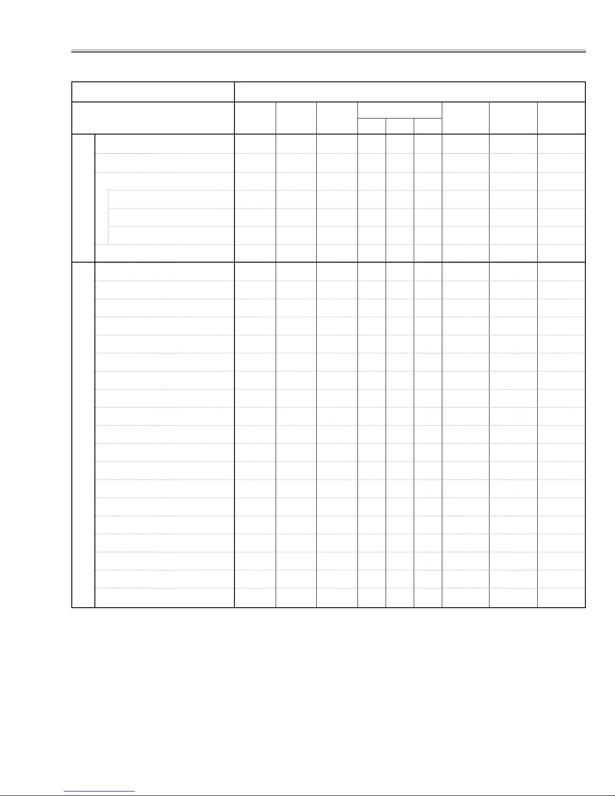
■ Adjustments after Parts Replacement
● : Adjustment necessary ❍ : Check necessary
Disassembly / Replaced Parts
Condenser
Lens
Relay
Lens
Polarized glass
R G B
Power
Board
Sub Power
Board
Main Board
Condenser lens adjustment ❍ ●
Relay lens a dj us tm en t
❍ ●
Contrast Adjustment
R-Contrast adjustment ●
G-Contrast adjustment ●
B-Contrast adjustment ●
Optical Adjustments
Output voltage adjustment ●
+16 V adjustment ●
Video center adjustment ●
NRS ad justment ●
PC p ed estal adjustment ●
PC gain adjustment ●
Black level a dj ustment ●
PC gamma shift adjustment ●
A/D r eference a dj us tm en t ●
AV pedestal adjustment ●
A/D i nput adjustment ●
Video pedestal adjustment ●
Electrical Adjustments
Video gain adjustment ●
HDTV p edestal adjustment ●
HDTV Gain adjustment ●
Video gamma shift a dj us tment ●
Common center adjustment ● ●
White balance adjustment ❍ ❍
-5-
■ Circuit Protections
This projector is equipped with the following circuit protections to operate in safety. If the abnormality occurs inside
the projector, it will automatically turn off by operating one of the following protection circuits.
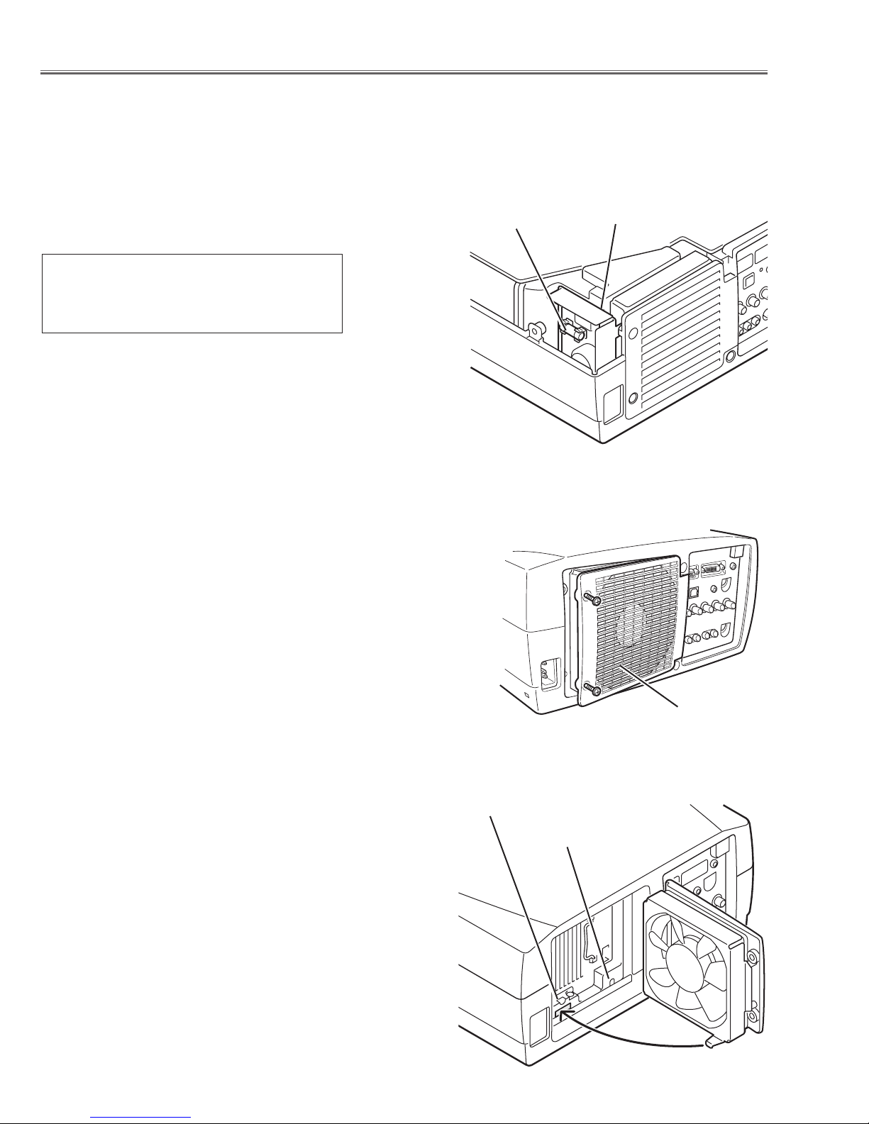
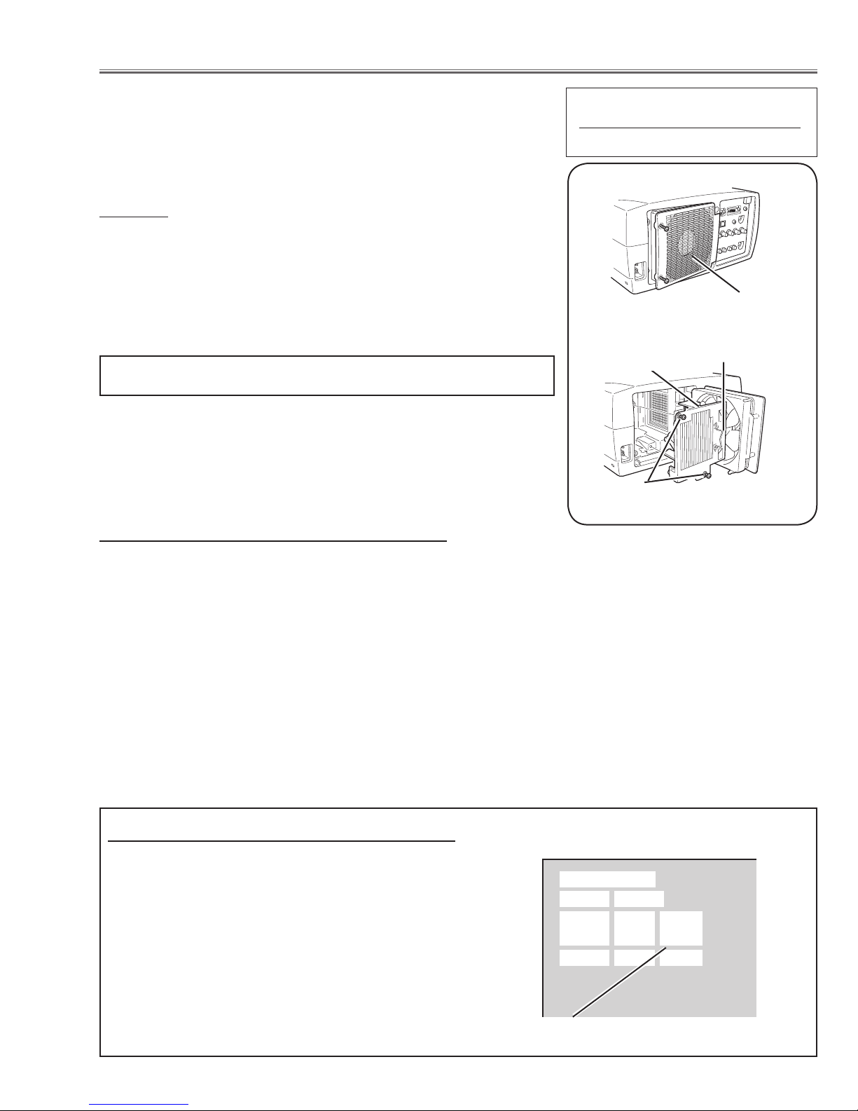
● Fuse
The fuse is located inside of the projector. When either the LAMP
indicator or the READY indicator is not illuminated, fuse may be
opened. Check the fuse as following steps.
It should be used the specified fuse as follows;
Fuse Part No.: 423 025 1201
TYPE T8AH 250V FUSE
LITTEL FUSE INC. TYPE 215008
How to replace the fuse
1. Remove the cabinet top following to “Mechanical
Disassemblies”.
2. Remove the fuse from fuse holder.
To install the fuse, take reversed step in the above.
Fuse
Line Filter Board
● Thermal switch
There is the thermal switch (SW905) inside of the projector to
prevent the internal temperature from rising abnormally. When
the internal temperature reaches near 90˚C, turn off the AC main
power supply automatically.
The thermal switch is not reset to normal automatically even if the
internal temperature becomes normal. Reset the thermal switch
following procedure.
Check the resistance between terminals of thermal switch by
using the tester. If it has high impedance, thermal switch may be
in operative.
How to reset the thermal switch
1. Loosen 2 screws and open the lamp cover.
2. Press the reset button on the thermal switch with a sharp-
pointed tool.
CAUTION:
Before press the reset button, disconnect the AC cord from the
projector.
● Interlock switch
The interlock switch (SW902) cuts off the AC mains power supply
when the lamp cover is removed. After opening the lamp cover for
replacing the lamp ass’y, place the lamp cover correctly otherwise
the projector can not turn on.
Lamp cover
Interlock switch
Thermal switch
-6-
Circuit Protections
● Warning temperature and power failure protection
The TEMP WARNING indicator flashes red and the projector will automatically turn off when the internal
temperature of the projector exceeds the normal temperature or when stopping cooling fans or when the internal
power supply lines are failed.
Check the following possible causes and wait until stopping the TEMP WARNING indicator flashing.
Possible causes
- Air filter is clogged with dust particles. Remove dust from the air filter by following instructions in the “Air filter care
and cleaning” below.
- Ventilation slots of the projector are blocked. In such an event, reposition the projector so that ventilation slots are
not obstructed.
- Check if projector is used at higher temperature place (Normal operating temperature is 5 to 35 ˚C or 41 to 95˚F)
If the TEMP WARNING indicator still continues to flash, there may be defects on cooling fans or power supply
circuits. Please check fan operation and power supply lines referring to the “Power Supply Lines Chart”.
Air filter care and cleaning
The removable air filter prevents dust from accumulation on the surface of the projection lens and projection mirror.
Should the air filter become clogged with dust particles, it will reduce the cooling fan’s effectiveness and may result
in internal heat build up and reduce the life of the projector.
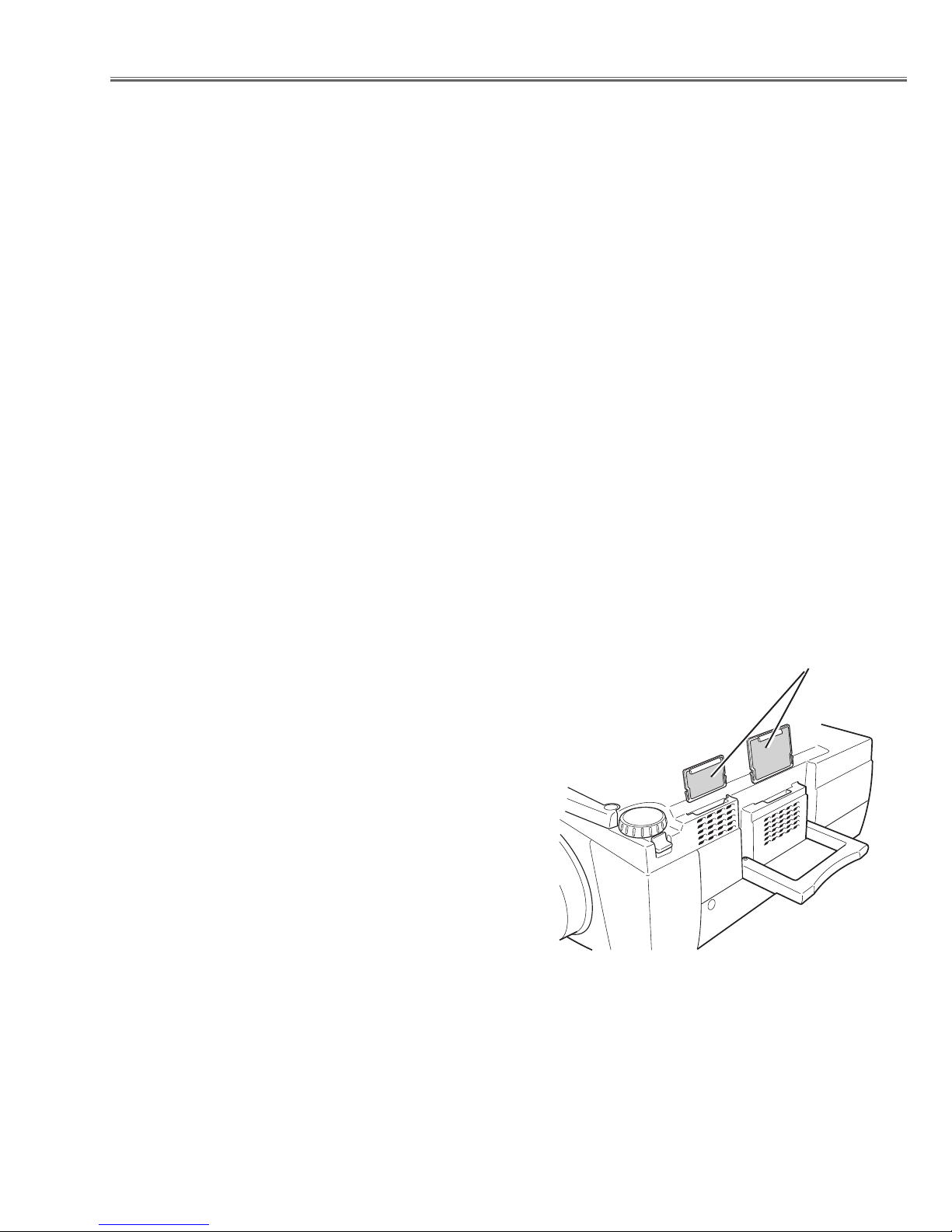
To clean up the air filters, follow the cleaning procedure below:
1. Turn the power off, and disconnect the AC power cord
from the AC outlet.
2. Turn the projector up side down and remove an air
filters by pulling the latches of them upward.
Air filters
3. Clean the air filters with brush or wash out the dust and
particles.
4. Replace each air filter properly. Make sure that the air
filters are fully inserted.
CAUTION:
Do not operate the projector with the air filter removed. The
dust is stuck on the LCD panel and the mirror, and it may
spoil the fine picture image.
Do not put the small parts into the air intake vents. It may
result in the malfunction of the projector. The air filter is
small parts. Take care that children don’t eat or swallow it.
RECOMMENDATION
We recommend to avoid dusty, smoky place for operating
the projector. Using in dusty place may cause the picture of poor quality.
When using under the dusty or smoky conditions, dust may accumulate on the LCD panel and lens inside it, and
may resultantly be projected on the screen together with the picture.
When the above symptoms are noticed, please clean up the LCD panel and lens following to the “Cleaning
Method”.
-7-
UP
■ Mechanical Disassemblies
Mechanical disassemble should be made following procedures in numerical order.
Following steps show the basic procedures, therefore unnecessary step may be ignored.
Caution:
The parts and screws should be placed exactly the same position as the original otherwise it may cause loss of
performance and product safety.
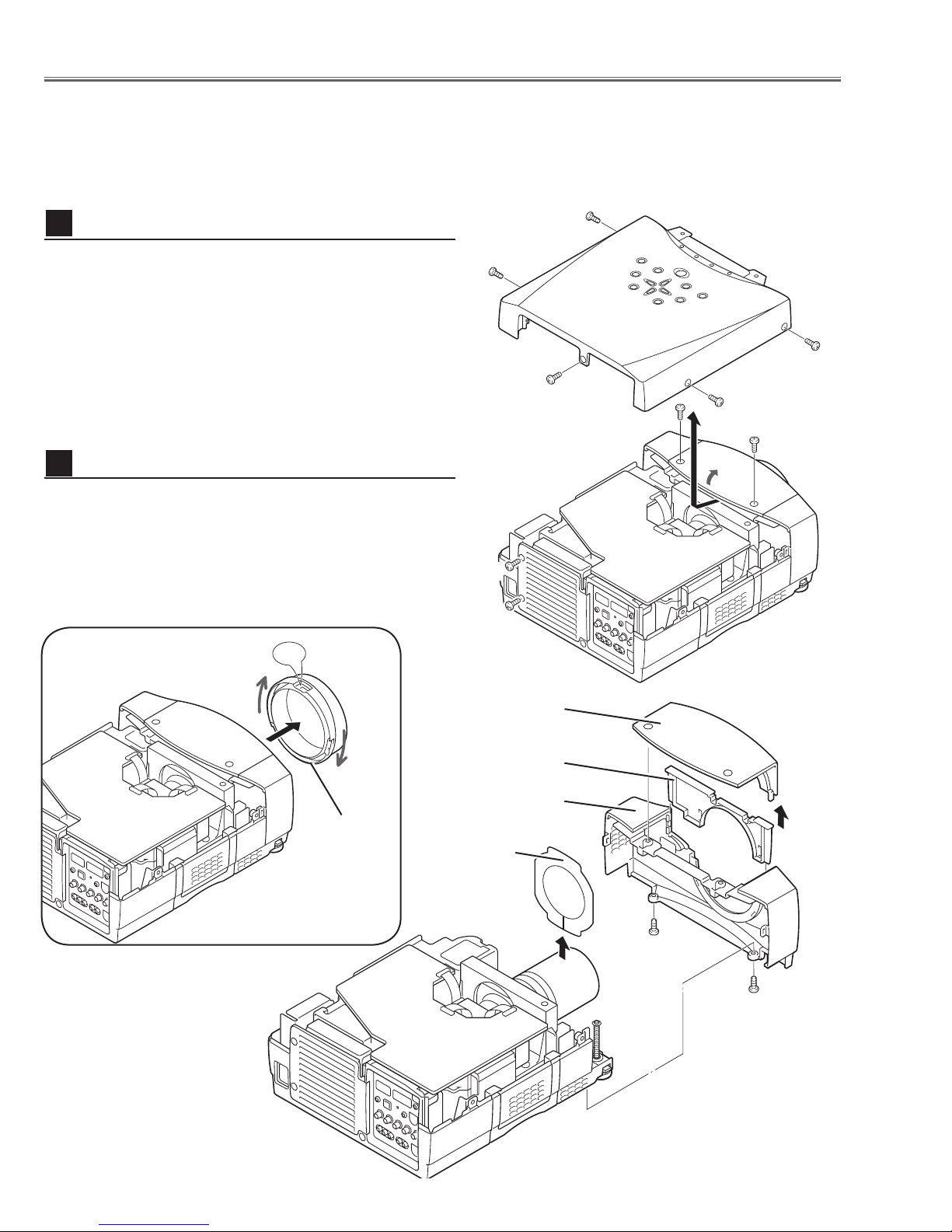
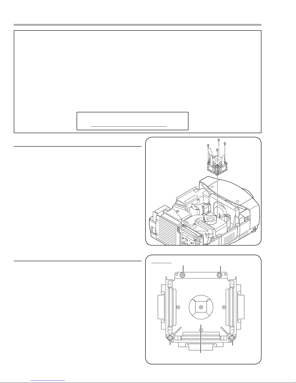
1
Cabinet Top removal
1 Remove 5 screws A, 2 screws B, and loosen 2 screws C,
and then take the Cabinet Top upward off.
Note: If you want to remove the Cabinet Front-Top only,
you do not need to remove screws
and Lens Front Cover.
2
Cabinet Front removal
A. Remove 2 screws B
1 Turn the Lens Front Cover counter-clockwise and to take
it off by pulling forward as shown in Fig.2-1.
2 Remove the Cabinet Front-Top, Lens Cover Holder and
Lens Cover upward off.
3 Remove 2 screws D to take the Cabinet Front off.
4 Remove the RC Board and speakers on the Cabinet
Front.
A
A
A
A
B
C
C
A
B
Fig.1
Lens
Front
Cover
Fig.2-1
Cabinet Front-Top
Lens Cover Holder
Cabinet Front
Lens Cover
D
D
Fig.2-2
-8-
Mechanical Disassemblies
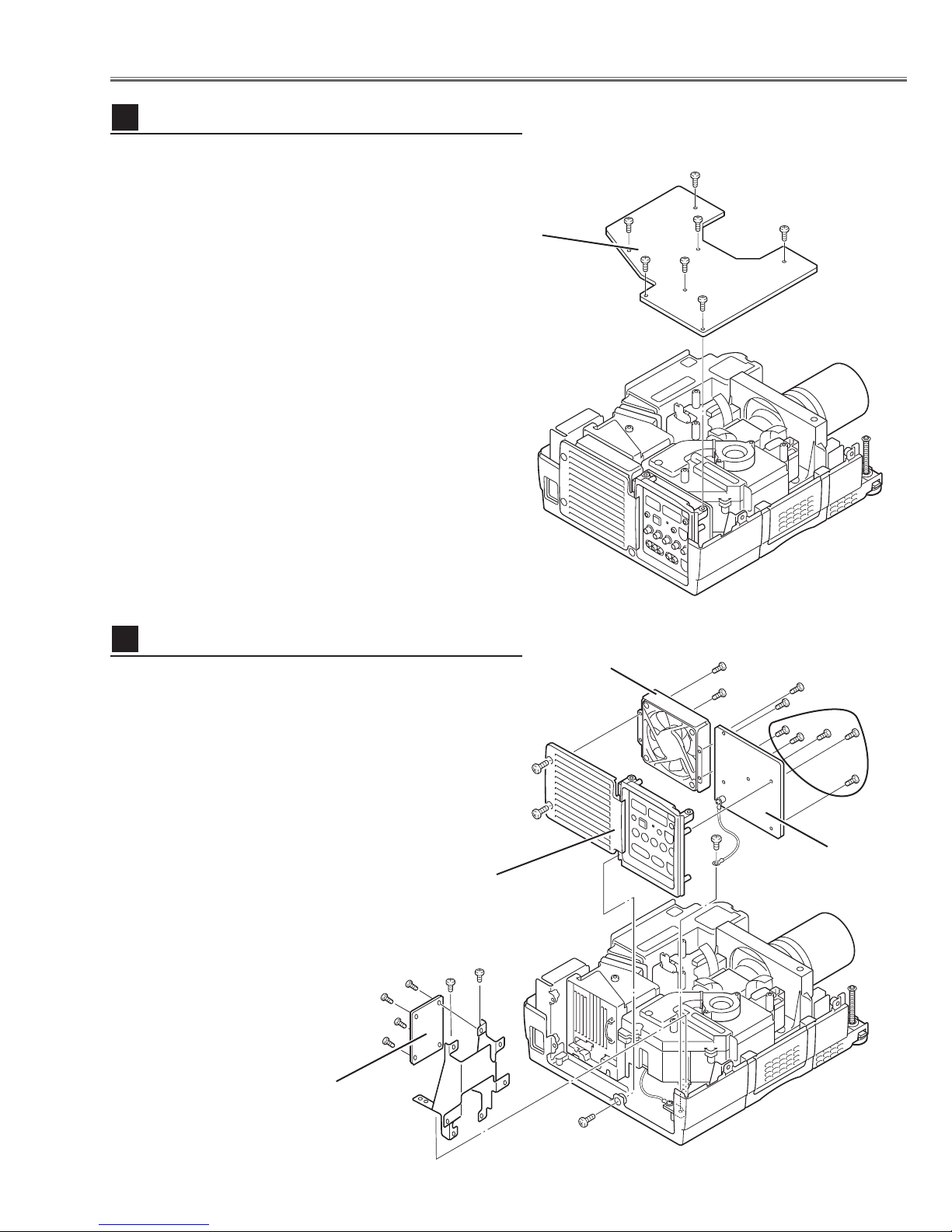
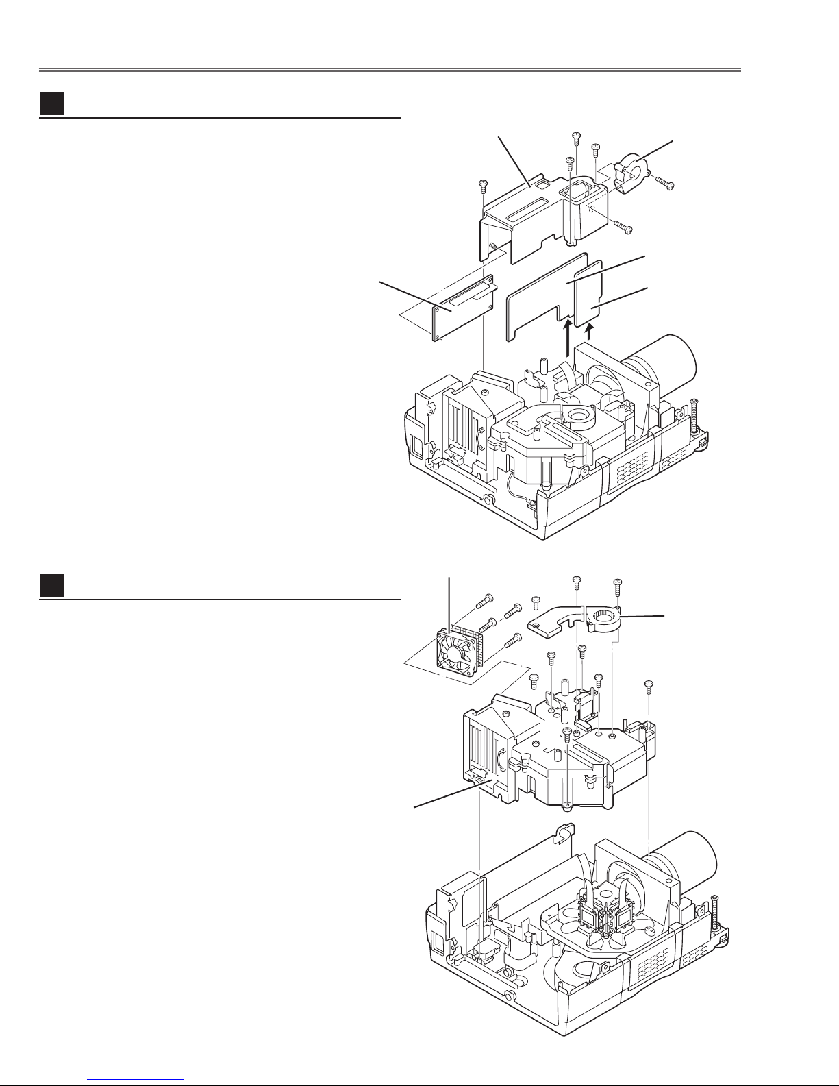
3
Main Board removal
1 Remove 7 screws to take the Main Board upward.
Main Board
4
AV, I/F Board & Rear Panel removal
1 Remove 1 screw A and take the Rear Panel ass’y
upward off.
2 Remove 4 screws B to take the fan (FN905) off.
3 Remove 5 screws C and 1 screw D to take AV Board
from the Rear Panel ass’y off.
4 Remove 2 screws E and grounding leads and then
pull up the I/F Board and Holder assy from the bottom
cabinet.
5 Remove 4 screws F to take the I/F Board.
Rear Panel Ass’y
E
F
F
F
F
E
FN905
Fig.3
B
B
D
B
B
C
AV Board
I/F Board
A
Fig.4
-9-
Mechanical Disassemblies
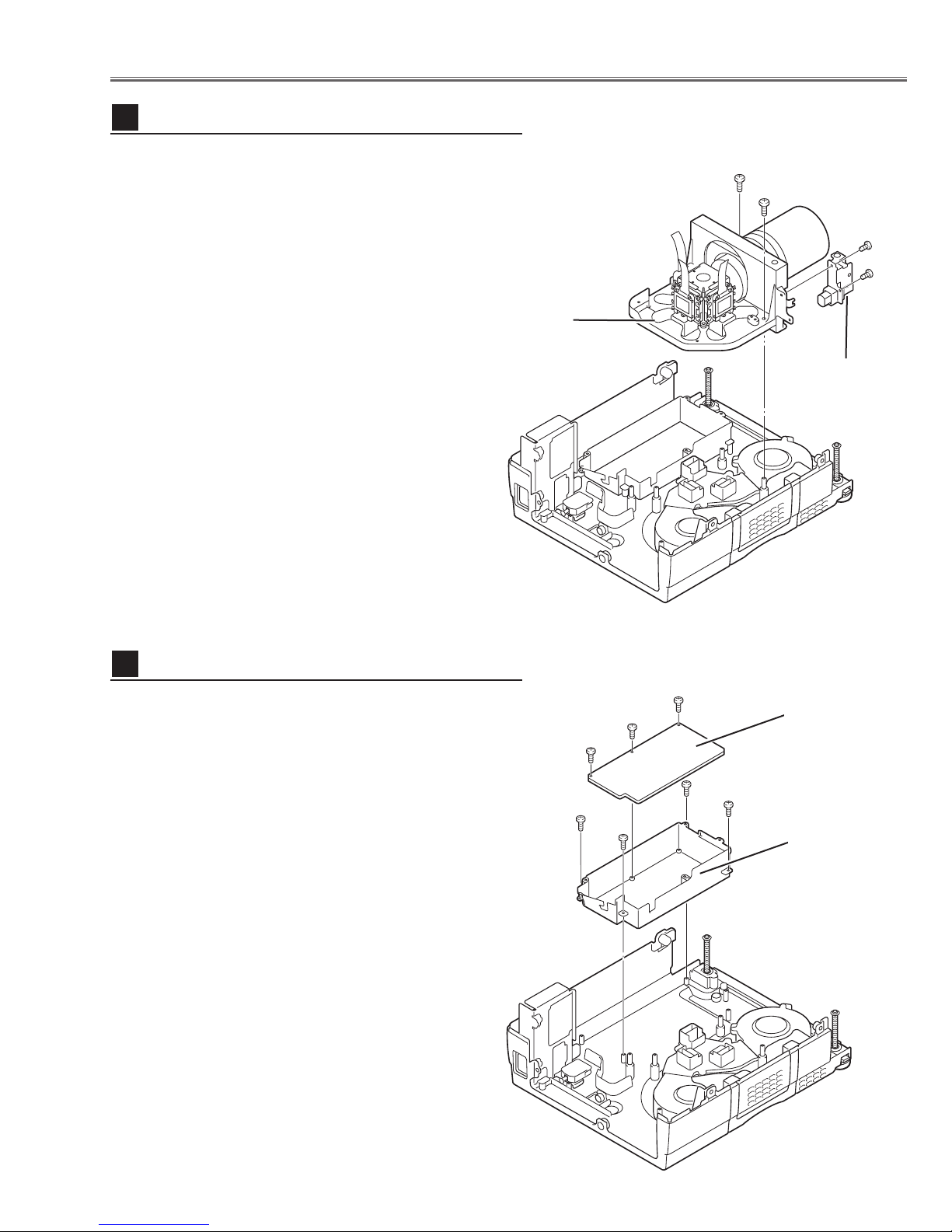
5
Lamp Ballast Unit removal
1 Remove 4 screws A to take the Ballast Cover upward
off.
2 Remove 2 screws B to take the Fan (FN903) off.
3 Remove the Sub Power Board and Drive Board by
pulling them upward.
Ballast Board
Ballast Cover
A
A
A
A
FN903
B
B
Sub Power
Board
Drive Board
6
Optical Unit removal
1 Remove 2 screws A and 4 screws B(small) and pull the
Optical Unit upward off.
2 Remove 4 screws C to take the Fan (FN906) off.
3 Remove 1 screws D to take the Fan (FN904) off and 2
screws
E to take the air duct off.
Optical Unit
FN906
Fig.5
E
E
C
C
C
B
A
A
D
FN904
B
B
B
Fig.6
-10-
Mechanical Disassemblies
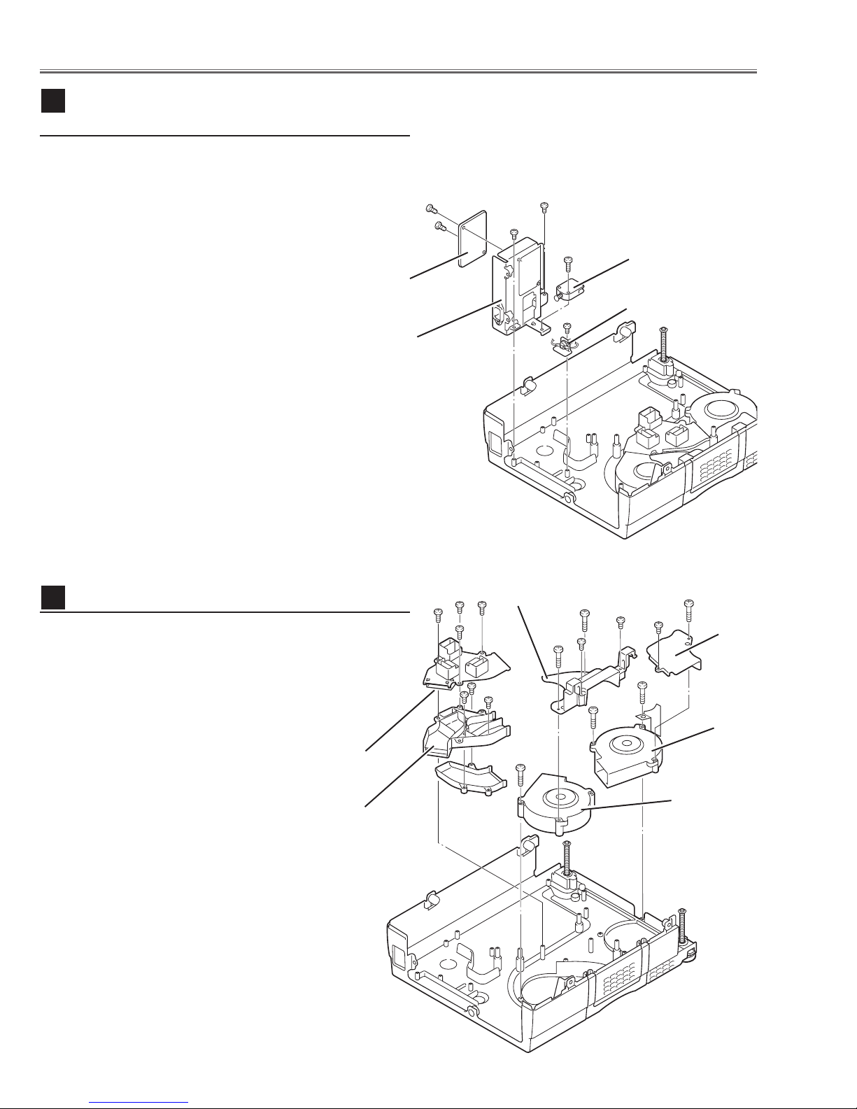
7
Prism Base removal
1 Remove 2 screws A to take the Prism Base ass’y
upward off.
2 Remove 2 screws B to take the Lens Shift Motor and
Sensor SW Holder from the Base.
Prism Base Ass’y
A
A
B
B
Motor and
Sensor Holder
8
Power Board removal
1 Remove 3 screws A to take the Power Board off.
2 Remove 4 screws B to take Holder off from the cabinet
bottom.
Fig.7
A
A
A
B
B
B
B
Power Board
Power Board
Holder
Fig.8
-11-
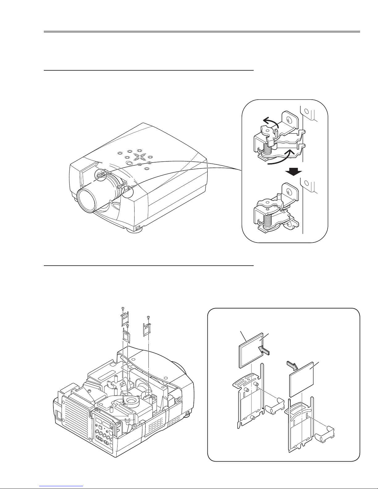
Mechanical Disassemblies
9
Line Filter Board & Interlock SW & Thermal
SW removal
1 Remove 1 screw A to take Interlock Switch(SW905).
2 Remove 2 screws B to take Filter Board Holder and
remove 2 screws
C to take Filter Board from the Holder.
3 Remove 1 screw D to take Thermal Switch(SW902).
C
C
B
B
A
Interlock Switch
(SW905)
Filter Board
Holder
10
Fans (FN901, FN902) removal
1 Remove 4 screws A to take Air-duct Top off.
2 Remove 1 screw B (small) and 1 screw C (big) to take
Duct Cover-A.
3 Remove 2 screws D to take Fan (FN901) off.
4 Remove 2 screws E (small) and 2 screws F (big) to take
Air-duct-A and Fan (FN902) off.
Thermal Switch
D
(SW902)
Fig.9
A A
A
A
Air-duct-A
F
F
E
E
D
D
C
B
Duct
Cover
-A
FN901
Air-duct
Top
Duct
Cover-B
F
FN902
Fig.10
-12-
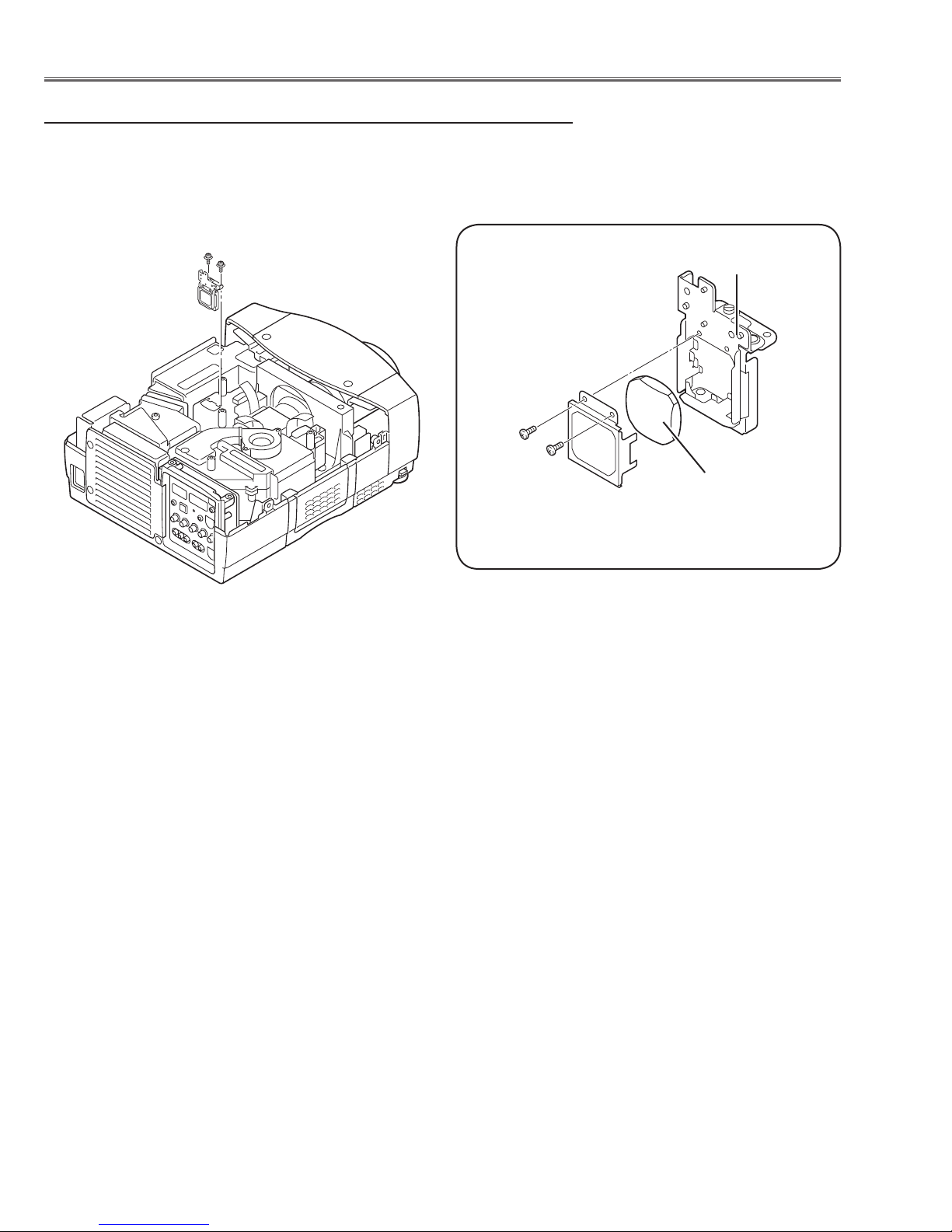
■ Optical Parts Disassemblies
Optical Filter
Polarized Grass
1
A
V
4
Z
1
5
*
*
*
Part No.
Film side
Before taking this procedure, remove Cabinet Top and Main Board following to the “Mechanical Disassemblies”.
Disassembly requires a 2.0mm or 2.5mm hex wrench and a slot screwdriver.
Projection Lens removal
1 Remove Cabinet Front-Top following to the chapter “Mechanical
Disassemblies”.
2 Loosen 2 screws A with 2.5mm hex wrench.
3 Unhook 2 hooks B on the both side of the lens and remove the Projection
Lens ass’y off.
B
A
B
A
Fig.1
Polarized Glass-In removal
1 Remove each hex screw and pull the Polarized Glass-In ass’y upward.
2 Remove a stopper and take the glass off upward.
Fig.1-2
Fig.2-1
-13-
Optical Pats Disassemblies
Relay Lens disassembly
1 Remove 2 hex screws A and pull the Relay Lens ass’y upward.
2 Remove 2 screws B to take the Lens off from the holder.
Note:
There is no mounting direction of the lens.
A
A
Holder
B
B
Relay Lens
Fig.3-1
Fig.3-2
-14-
Optical Filter(WV)
Optical Filter(WV)
Optical Filter(WV)
Optical Filter(WV)
Polarized Glass
Polarized Glass
Polarized Glass
Polarized Glass
1A
V4Z15B18
0
1AV4Z15B18
0
Film
R-PANEL
B-PANEL
G-PANEL
PRISMPRISM
Film side
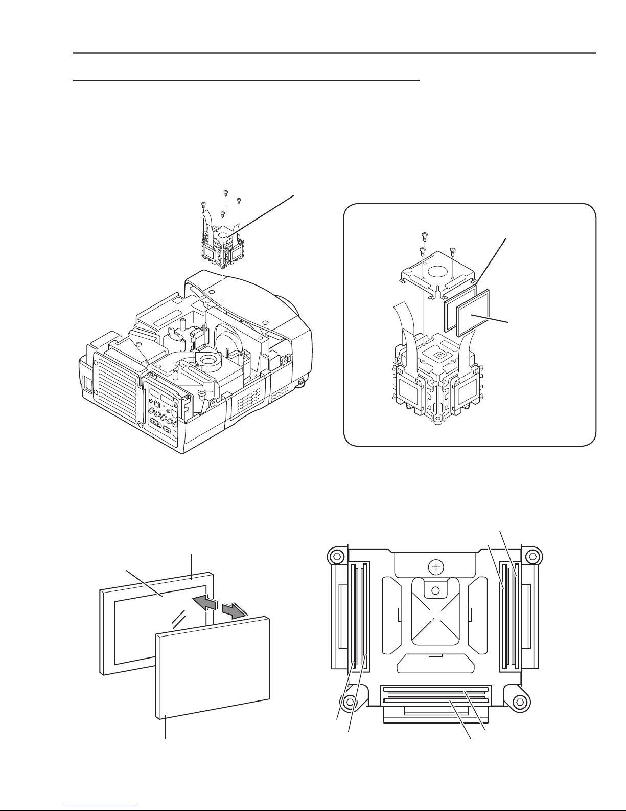
Optical Pats Disassemblies
Polarized Glass-Out and Optical Filter-Out(WV) removal
1 Remove 4 hex screws A and take the LCD/Prism ass’y off upward.
2 Remove 3 screws B and take the Glass Holder, and then pull the
polarized Glass-Out and the optical filter-out(WV) upward off. These
glasses are mounted for R, G and B LCD panels respectively.
Note:
To avoid the CG and focus alignments slipping off, please be careful to
handle the LCD/Prism ass'y.
Note:
Do not replace the LCD panel
separately otherwise it can
not obtain proper picture.
A
A
A
LCD Panel/Prism Ass’y
B
B
B
Polarized GlassOut
Optical FilterOut(WV)
Fig.4-1 Fig.4-2
-15-
Fig.4-3
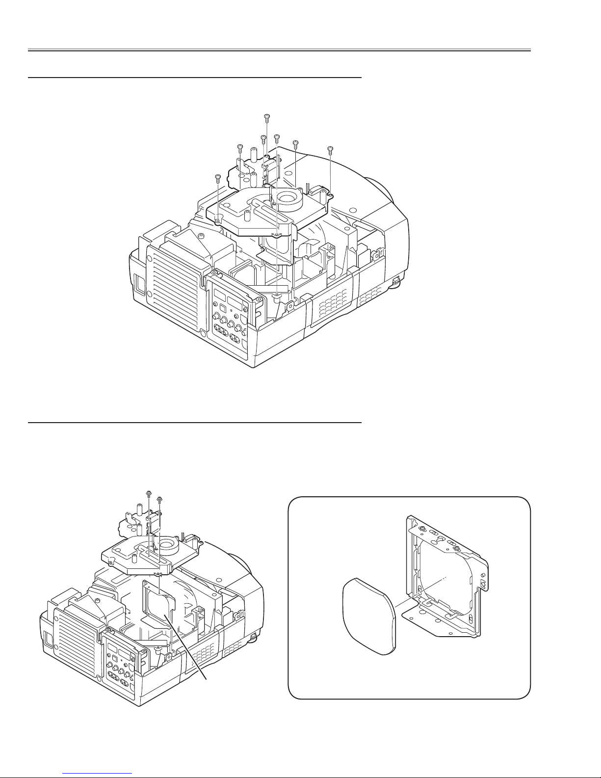
Optical Parts Disassemblies
Optical Unit Top removal
1 Remove 7 screws to take the Optical Unit Top off upward.
Condenser Lens disassembly
1 Remove 2 hex screws A and take the Condenser Lens ass’y.
2 Release 4 hooks B to take the Lens off from the holder.
A
A
Fig.5
* Lens should be placed
as the flat surface side
comes to the holder
side.
Condenser Lens
Fig.6-1
-16-
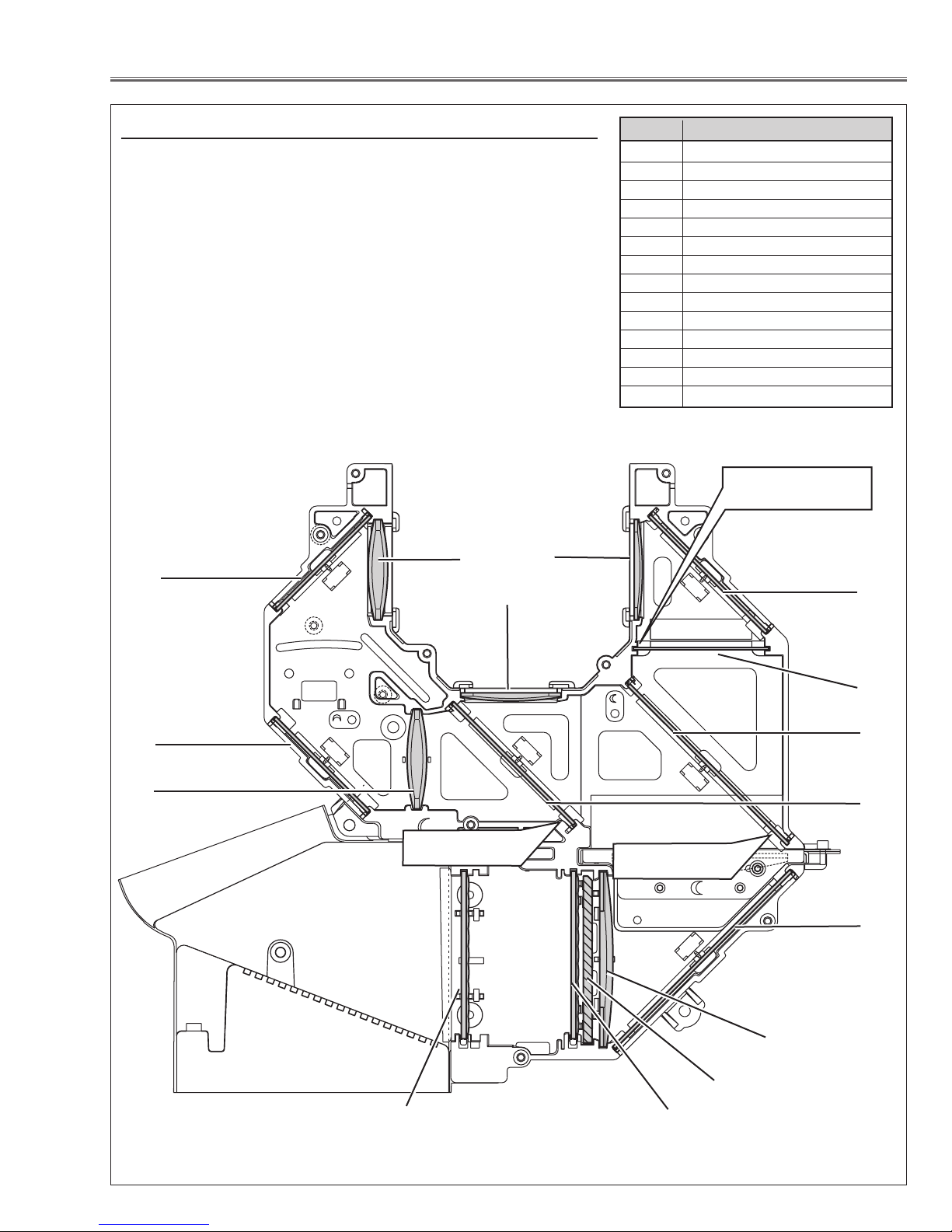
Optical Parts Disassemblies
Locations and Directions
When the optical parts in the optical unit mounting or assembling,
the parts must be mounted in the specified location and direction as
shown in figure below.
1
3
14
2
Key No. Description
1 Condenser lens (R)
2 Condenser lens
3 Condenser lens
4 Mirror (B)
5 Optical filter (UV cut)
6 Dichroic mirror (B
7 Dichroic mirror (G)
8 Mirror (W)
9 Condenser lens (IN)
10 PBS (prism beam splitter)
11 Integrator lens (OUT)
12 Integrator lens (IN)
13 Relay lens (IN)
14 Mirror (R)
The cutting corner
comes to this side up.
4
14
13
The printed marker
comes this side.
12
The printed marker
comes this side.
11
5
6
7
8
9
10
Fig.7
-17-
■ LCD Panel/Prism Ass’y Replacement
IMPORTANT NOTICE on LCD Panel/Prism Ass'y Replacement
LCD panels used for this model can not be replaced separately. Do not disassemble the LCD Panel/Prism Ass’y.
These LCD panels are installed with precision at the factory. When replacing the LCD panel, should be replaced
whole of the LCD panels and prism ass’y at once.
After replacing LCD Panel/Prism ass’y, please check the following adjustments.
- Check the “Condenser Lens Adjustment” and “Relay Lens Adjustment” following to chapter “Optical
Adjustment”.
- Check the “White Balance Adjustment” and “Common Centre Adjustment” following to chapter “Electrical
Adjustment”.
- Check the white uniformity on the screen.
If you find the color shading, please adjust the white uniformity by using the proper computer and “Color
Shading Correction” software supplied separately. The software can be ordered as follows;
COLOR SHADING CORRECTION SOFTWARE
Service Parts No. 645 051 2308
LCD Panel/Prism Ass’y removal
1 Remove the cabinet top and main board following to
“Mechanical Disassemblies”.
2 Remove 4 screws by using the 2.0 mm hex driver and
take the LCD Panel/Prism ass’y off upward from the
optical unit.
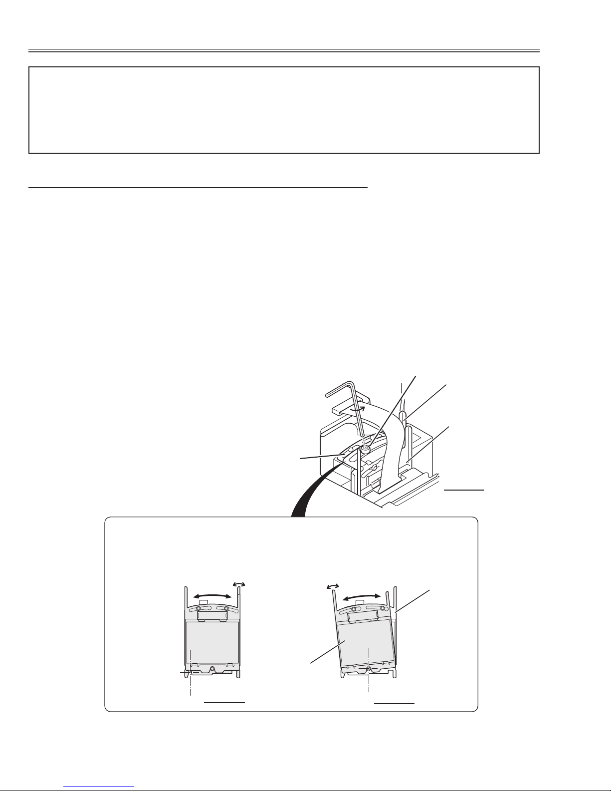
Note on LCD Panel/Prism Ass’y Mounting
After replacing or installing the LCD Panel/Prism ass'y,
please make sure to obtain the best focus in both TELE
and WIDE zoom. If the focus adjustment is required,
please adjust the positioning of LCD Panel/Prism Ass’y by
following the below procedure.
Note:
Do not replace the LCD
panel separately otherwise
it can not obtain proper
picture.
Top View
A
A
Mounting Procedure:
1 Loosen 4 screws A on the LCD Panel/Prism ass'y with
2.0 mm hex driver.
2 Turn the projector on and project the image with WIDE
zoom, and adjust the FOCUS control to obtain the best
focus.
3 Turn the ZOOM control to the TELE position.
4 Move the LCD Panel/Prism Ass’y backward or forward
(about 0mm ~ 0.8mm) to obtain the proper focus.
Confirm the focus at TELE and WIDE zoom.
5 Tighten 4 screws A to fix the LCD Panel/Prism ass'y.
-18-
A
LCD Panel/Prism Ass’y
A
■ Lamp Replacement
Service Mode
Input 1
Group No. Data
40 0 123
Ver.
1.00 .00
WARNING:
- For continued safety, replace with a lamp assembly of the same type.
- Allow the projector to cool for at least 45 minutes before you open the
lamp cover. The inside of the projector can become very hot.
- Do not drop the lamp module or touch the glass bulb! The glass can
shatter and cause injury.
Procedure
1 Turn off the projector and disconnect the AC cord. Allow the projector to
cool for at least 45 minutes.
2 Loosen 2 screws with a screwdriver and open the lamp cover.
3 Loosen 2 screws and pull out the lamp assembly by grasping the
handle.
4 Replace the lamp assembly securely and tighten 2 screws.
5 Close the lamp cover and tighten 2 screws.
6 Connect the AC cord to the projector and turn on.
7 Reset the Lamp Replace Counter, see below explanation.
Note:
- Do not reset the Lamp Replace Counter, except after lamp is replaced.
- The projector can not be turned-on with lamp cover removed, because
when the lamp cover is removed, the interlock switch is also released to
switch off the mains power for safety.
ORDER REPLACEMENT LAMP
Type No. Service Parts No.
POA-LMP38 610 293 5868
Lamp cover
Handle
Lamp Assembly
Screws
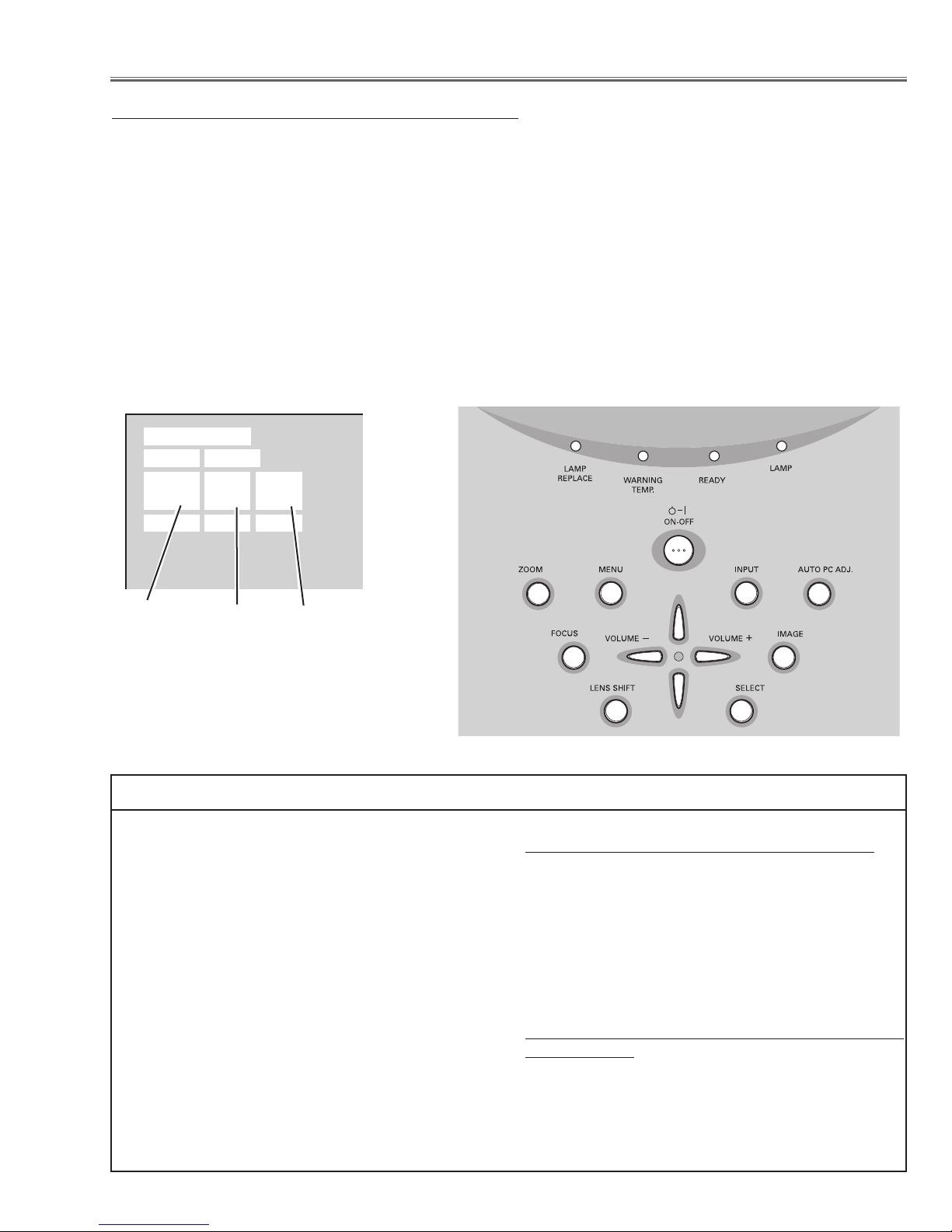
How to reset Lamp Replace Counter
1 Turn the projector on, and press the MENU button
and the on-screen menu will appear. Press the
POINT LEFT/RIGHT buttons to move a red frame
pointer to SETTING menu icon.
2 Press the POINT DOWN button to move a red frame
pointer to “Lamp counter reset” and then press
the SELECT button. The message “Lamp replace
counter reset?” is displayed. Move the pointer to [Yes]
and the press the SELECT button.
3 Another confirmation dialog box appears and select
[Yes] to reset Lamp Replace Counter .
Please refer to t he owners m anual for fur ther
information.
How to check Lamp Replace Counter
The LAMP REPLACEMENT indicator will illuminate
when the Lamp Replace Counter reaches 1000 hours.
This is to indicate that lamp replacement is required.
You can check the lamp replace counter following to
below procedure.
1 Press and hold the pointer UP on the projector for
more than 20 seconds.
2 The Lamp replace Counter service menu appears
on the screen briefly. For example, when the value of
data indicates “123”, the accumulated operation time
Recommendation
Should the air filter become clogged with dust particles,
it will reduce the cooling fan’s effectiveness and may
result in internal heat build up and short lamp life. We
recommend cleaning the air filter after the projection
lamp is replaced.
Refer to “Air Filter Cleaning”.
is 123 hours.
Lamp replace counter data
-19-
■ Optical Adjustments
Optical Filter(WV)
Optical Filter(WV)
Polarized Glass
Polarized Glass
Before taking optical adjustments below, remove the Cabinet Top and Main Board following to the “Mechanical
Disassemblies”
Adjustments require a 2.0mm hex wrench and a slot screwdriver.
Note: Do not disconnect connectors K8L, K8X, K8D, K8G and K8E on the main board, because the projector can
not turn on due to operate the power failure protection.
Contrast adjustment
[Before Adjustment]
- Input a 100% of black raster signal.
[R/G/B-CONTRAST ADJUSTMENT]
1 Loosen a screw A (Fig.1-1/1-4) on the polarized glass mounting base
which you intend to adjust.
2 Turn the polarized glass mounting base with knob B as shown in Fig.1-2
to obtain the darkest brightness on the screen. (The polarized glass and
optical filter move together.)
3 Turn the optical filter mounting base with know C as shown in Fig.1-3
to obtain the black color uniformity on the screen.(Move only the optical
filter.)
4 Tighten the screw A to fix the polarized glass mounting base.
Repeat steps 1 to 4 for remaining R, G or B contrast adjustment.
Polarized glass
mounting base
B
A
C
Fig.1-1
Fig.1-2
Fig.1-3
-20-

Optical Adjustments
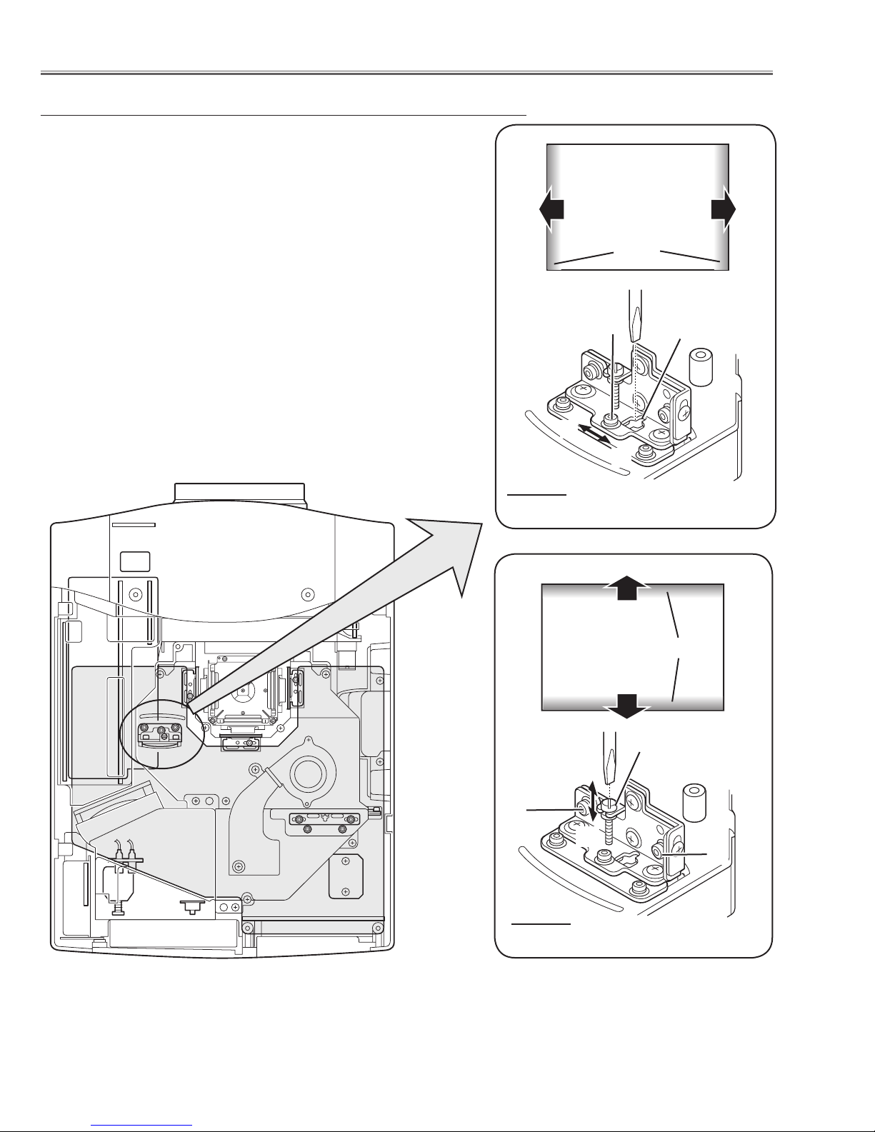
Condenser Lens adjustment
1 Turn the projector on by a state of without FPC cables.
2 Adjust the adjustment base of condenser lens ass’y to make color
uniformity in white.
1) If the shading appears on the left or right of the screen as
shown in Fig.2-1, loosen 2 screws A with the 2.0mm hex
driver, and adjust the slot B to make color uniformity in green
by using a slot screwdriver.
2) If the shading appears on the top or bottom of the screen as
shown in
and adjust the slot D to make color uniformity in green by
using a slot screwdriver
Fig.2-2, loosen 1 screw C with the 2.0mm hex driver,
3 Tighten screws A and C to fix the Condenser lens unit.
Note:
The relay lens adjustment must be carried out after completing this
adjustment.
A
a
Fig.2-1
Moving of slot B
White
b
Slot B
A
Slot D
Fig.2-2
Moving of Slot D
White
C
x
y
-21-
Optical Adjustments
Relay lens-Out adjustment
1 Turn the projector on by a state of without FPC cables.
2 Adjust the adjustment base of relay lens ass’y to make color
uniformity in white.
1) If the cyan bar appears on the left or right of the screen as
shown in Fig.4-1, loosen 1 screw A with the 2.0mm hex driver,
and adjust the slot B to make color uniformity in white by using
a slot screwdriver.
2) If the cyan bar appears on the top or bottom of the screen as
shown in
and adjust the screw D to make color uniformity in white by
using a slot screwdriver.
Fig.4-2, loosen 2 screws C with the 2.0mm hex driver,
3 Tighten the screws A and C to fix the relay lens unit.
A
a
b
Slot B
Fig.4-1
Moving of slot B
x
C
y
Screw D
C
Fig.4-2
Moving of slot D
-22-
Service Mode
Input 1
Group No. Data
0 0
32
Ver.
1.00 .00
■ Electrical Adjustments
● Service Adjustment Menu Operation
To enter the service mode
To enter the “Service Mode”, press and hold the MENU and IMAGE button on the projector at the same time for
more than 3 seconds. The service menu appears on the screen as follows.
To adjust service data
Select the adjustment group no. by pressing the MENU button, and select the adjustment item no. by pressing the
pointer UP or DOWN button, and change the data value by pressing the VOLUME – or VOLUME + button. Refer
to the “Service Adjustment Data Table” for further description of adjustment group no., item no. and data value.
To exit the service mode
To exit the service mode, press the POWER ON-OFF button on the projector or remote control unit.
Group No.
● Memory IC Replacement
IC808 on the main board stores the data for the
service adjustments, and should not be replaced
except for the case of defective device.
If replaced, it should be performed the re-adjustments
following to the “Electrical Adjustments”.
The data of lamp replacement monitor timer is stored
in the IC808.
Please note that the lamp replace counter is reset
when the memory IC (IC808) is replaced.
(Lamp replace counter can not be set to the previous
value.)
● Caution to memory IC replacement
When IC808 is replaced with new one, the CPU writes
down the default data of the service adjustments
to the replaced IC, refer to the service adjustment
table. As these data are not the same data as factory
shipped data, it should be required to perform the
Item No.
Data value
re-adjustments following to the “Electrical Adjustments”.
Please note that the lamp replace counter is reset.
● Caution of Main Board replacement (in the case
IC808 is not defective)
When the main board is replaced, IC808 should
be replaced with the one on previous main board.
After replacement, it should be required to perform
the re-adjustments following to the “Electrical
Adjustments”.
In this case, the lamp replace counter can be kept the
value as before.
-23-
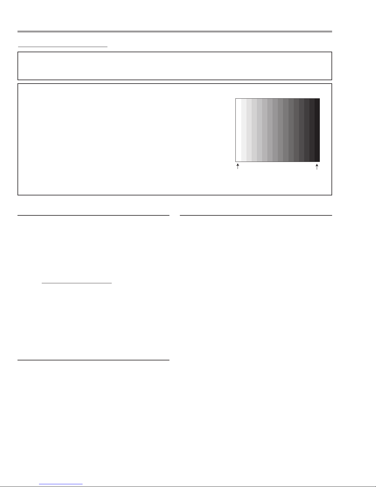
White 100%
Black 100%
Electrical Adjustments
● Circuit Adjustments
CAUTION: The each circuit has been made by the fine adjustment at factory. Do not attempt to adjust the
following adjustments except requiring the readjustments in servicing otherwise it may cause loss of
performance and product safety.
[Adjustment Condition]
● Input signal
Video signal ......................... 1.0Vp-p/75Ω terminated, 16 steps gray
scale (Composite video signal)
Computer signal .................... 0.7Vp-p/75Ω terminated, 16 steps gray
scale pattern (XGA)
Component Video signal ....... 0.7Vp-p/75Ω terminated, 16 steps gray
scale (Component video signal with
480p or 1080i format)
● Picture control mode .............. “STANDARD” mode unless otherwise
noted.
Note:
* Please refer to “Service Adjustment Menu Operation” for entering to the
service mode and adjusting the service data.
Output Voltage adjustment
After replacing the Power Board readjust the Output
voltage adjustment as follows.
1. Connect a digital voltmeter to pin 1 (+) of K6A and
chassis ground (-).
2. Adjust the voltage by using
board as following.
AC Input Reading
230V 370 ±2Vdc
or 120V 340 ±2Vdc
Caution:
Be sure to connect the lamp when taking this
adjustment.
VR601 on the power
Video Center adjustment
1. Receive the 16-step gray scale computer signal with
Input 1 [COMPUTER] mode.
2. Enter the service mode.
3. Connect a digital voltmeter to test point “TP531” (+)
and chassis ground (-).
4. Select group no. “
value to adjust the voltage to be 7.30 ±0.1Vdc.
5. Connect a digital voltmeter to test point “TP501” (+)
and chassis ground (-).
6. Select item no. “
the voltage to be 7.30 ±0.1Vdc.
7. Connect a digital voltmeter to test point “TP561” (+)
and chassis ground (-).
8. Select item no. “
the voltage to be 7.30 ±0.1Vdc.
16 steps gray scale pattern
11”, item no. “0” and change data
1” and change data value to adjust
2” and change data value to adjust
Low Voltage adjustment
1. Receive the 16-step gray scale video signal with
Input 3 [VIDEO] mode.
2. Connect a digital voltmeter to pin 3 (+) of CN6A and
chassis ground (-).
3. Adjust the voltage to be
VR681 on the power board.
15.8 ±0.1Vdc by using
-24-
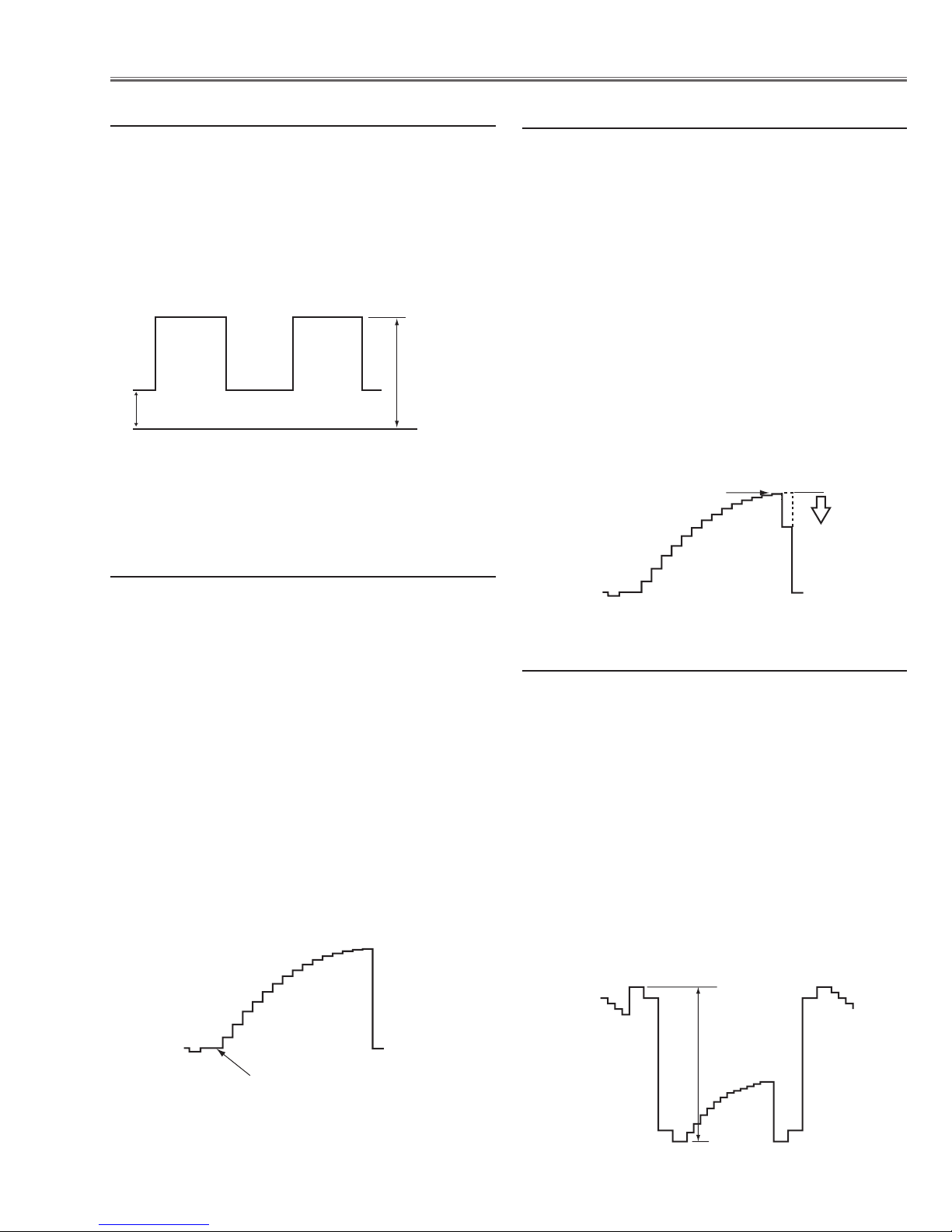
Electrical Adjustments
Pedestal Lebel = Black Lebel
(a)
(b)
GND
(a)
black level
black level
White Level
(a)
NRS adjustment
1. Receive the a6-step gray scale computer signal with
Input 1 [COMPUTER] mode.
2. Enter the service mode.
3. Connect an oscilloscope to test point “TP3671” (+)
and chassis ground (-).
4. Select group no. “
value to adjust amplitude “a” to be 2.0 ±0.1V.
5. Select item no. “4” and change data value to adjust
amplitude “b” to be 7.5 ±0.1V.
11”, item no. “3” and change data
PC Gain adjustment
1. Receive the 16-step gray scale computer signal with
Input 1 [COMPUTER] mode.
2. Enter the service mode.
3. Connect an oscilloscope to test point “TP531” (+)
and chassis ground (-).
4. Select group no. “
to “600”, and then decrease data to adjust waveform
“a” to be minimum amplitude.
5. Connect an oscilloscope to test point “
and chassis ground (-).
6. Select item no. “
then decrease data to adjust waveform “a” to be
minimum amplitude.
7. Connect an oscilloscope to test point “
and chassis ground (-).
8. Select item no. “
then decrease data to adjust waveform “a” to be
minimum amplitude.
10”, item no. “3” and set data value
TP501” (+)
4” and set data value to “600”, and
TP561” (+)
5” and set data value to “580”, and
PC Pedestal adjustment
1. Receive the 16-step gray scale computer signal with
Input 1 [COMPUTER] mode.
2. Enter the service mode.
3. Connect an oscilloscope to test point “TP531” (+)
and chassis ground (-).
4. Select group no. “
value to adjust the pedestal level and black level to
be the same level.
5. Connect an oscilloscope to test point “
and chassis ground (-).
6. Select item no. “
the pedestal level and black level to be the same
level.
7. Connect an oscilloscope to test point “
and chassis ground (-).
8. Select item no. “
the pedestal level and black level to be the same
level.
500”, item no. “0” and change data
TP501” (+)
1” and change data value to adjust
TP561” (+)
2” and change data value to adjust
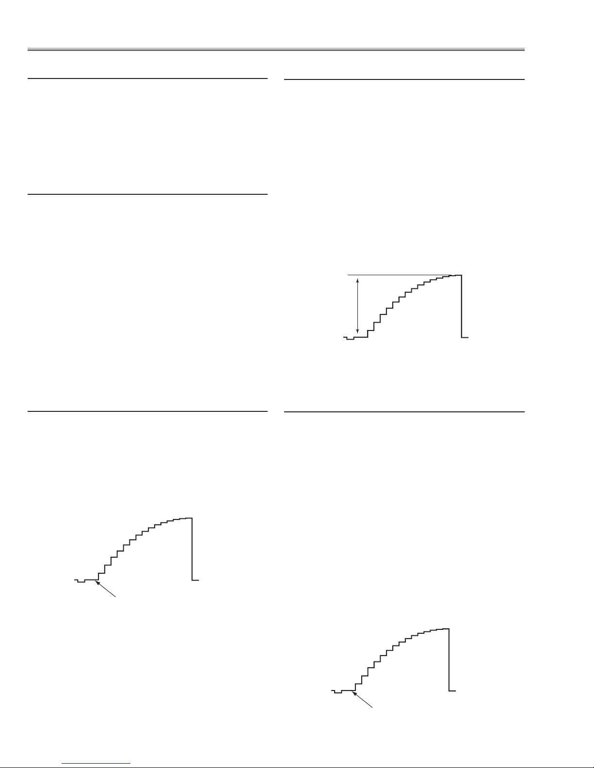
Black Level adjustment
1. Receive the 16-step gray scale computer signal with
Input 1 [COMPUTER] mode.
2. Enter the service mode.
3. Connect an oscilloscope to test point “TP531” (+)
and chassis ground (-).
4. Select group no. “
value to adjust amplitude “a” to be 9.0 ±0.1V.
5. Connect an oscilloscope to test point “TP501” (+)
and chassis ground (-).
6. Select item no. “
amplitude “a” to be 9.0 ±0.1V.
7. Connect an oscilloscope to test point “TP561” (+)
and chassis ground (-).
8. Select item no. “
amplitude “a” to be 9.0 ±0.1V.
11”, item no. “8” and change data
9” and change data value to adjust
10” and change data value to adjust
-25-
Electrical Adjustments
Pedestal Lebel = Black Lebel
(a)
Pedestal Lebel = Black Lebel
PC Gamma Shift adjustment
1. Receive the 16-step gray scale computer signal with
Input 1 [COMPUTER] mode.
2. Enter the service mode.
3. Select group no. “10”, item no. “6” and change data
value to reproduce the proper gray scale picture on
the screen.
A/D Reference adjustment
1. Receive the 16-step gray scale computer signal with
Input 3 [VIDEO] mode.
2. Enter the service mode.
3. Connect a digital voltmeter to test point “TPVRB” (+)
and chassis ground (-).
4. Select group no. “
value to adjust the voltage to be 0.7 ±0.1Vdc.
5. Connect a digital voltmeter to test point “TPGVRT”
(+) and chassis ground (-).
6. Select item no. “
the voltage to be 2.2 ±0.1Vdc.
11”, item no. “11” and change data
12” and change data value to adjust
A/D Input adjustment
1. Receive the 16-step gray scale video signal with
Input 3 [VIDEO] mode.
2. Enter the service mode.
3. Connect an oscilloscope to test point “TP13G” (+)
and chassis ground (-).
4. Select group no. “
value to adjust amplitude “a” to be 1.35 ±0.1V. If not,
use item no. “1” for fine adjustment.
5. Connect an oscilloscope to test point “TP13B” (+)
and chassis ground (-).
6. Select item no. “
amplitude “a” to be 1.35 ±0.1V.
7. Connect an oscilloscope to test point “TP13R” (+)
and chassis ground (-).
8. Select item no. “
amplitude “a” to be 1.35 ±0.1V.
2”, item no. “1” and change data
3” and change data value to adjust
4” and change data value to adjust
AV Pedestal adjustment
1. Receive the 16-step gray scale video signal with
Input 3 [VIDEO] mode.
2. Enter the service mode.
3. Connect an oscilloscope to test point “TP13G” (+)
and chassis ground (-).
4. Select group no. “
value to adjust the pedestal level and black level to
be the same level.
2”, item no. “0” and change data
Note: This adjustment should be done after VIDEO
Pedestal adjustment.
Video Pedestal adjustment
1. Receive the 16-step gray scale video signal with
Input 3 [VIDEO] mode.
2. Enter the service mode.
3. Connect an oscilloscope to test point “TP531” (+)
and chassis ground (-).
4. Select group no. “
value to adjust the pedestal level and black level to
be the same level.
5. Connect an oscilloscope to test point “
and chassis ground (-).
6. Select item no. “
the pedestal level and black level to be the same
level.
7. Connect an oscilloscope to test point “
and chassis ground (-).
8. Select item no. “
the pedestal level and black level to be the same
level.
11”, item no. “15” and change data
TP501” (+)
16” and change data value to adjust
TP561” (+)
17” and change data value to adjust
-26-
 Loading...