

Page 1
LCD Projection Monitor
MODEL PLV-55WM1
Owner’s Manual
Page 2

2
Table of Contents
TRADEMARKS
● Apple, Macintosh, and PowerBook are trademarks or registered trademarks of Apple Computer,Inc.
● IBM, VGA, XGA, and PS/2 are trademarks or registered trademarks of International Business Machines, Inc.
● Each name of corporations or products in the owner's manual is a trademark or a registered trademark of its respective
corporation.
Table of Contents . . . . . . . . . . . . . . . . . . . . . . . . .2
To the Owner . . . . . . . . . . . . . . . . . . . . . . . . . . . . .3
Safety Instructions . . . . . . . . . . . . . . . . . . . . . . . .4
Compliance . . . . . . . . . . . . . . . . . . . . . . . . . . . . . .5
Features and Design . . . . . . . . . . . . . . . . . . . . . . .6
Installation . . . . . . . . . . . . . . . . . . . . . . . . . . . . . . .7
Installing the LCD Projection Monitor 7
Part Names and Functions . . . . . . . . . . . . . . . . . .8
Front 8
Back 9
Front Jacks 10
Rear Terminals 11
Remote Control 12
Remote Control Operating Range 13
Remote Control Batteries Installation 13
Remote Control Code 14
Preparation . . . . . . . . . . . . . . . . . . . . . . . . . . . . .15
Connecting the AC Power Cord 15
Connecting to a Computer and Video Equipment
(Video, S-Video) 16
Connecting to Video Equipment
(Component, DVI compatible with HDCP) 17
Basic Operation . . . . . . . . . . . . . . . . . . . . . . . . . .18
Turning On the LCD Projection Monitor 18
Turning Off the LCD Projection Monitor 18
Sound Adjustment 19
Audio Selection 19
Lamp Control Function 20
Picture Freeze Function 20
On-Screen Menu 21
Menus 22
Audio Adjustment 24
Video Input . . . . . . . . . . . . . . . . . . . . . . . . . . . . .25
Input Source Selection (INPUT 3 / RGB, Video
(Video conference), Component) 25
Input Source Selection
(INPUT 4 / Video (Video conference), S-video,
Component) 26
Input Source Selection
(INPUT 5 / Video (Video conference) ) 27
Video System Selection 28
Image Level Selection 29
Image Level Adjustment 30
Screen Size Adjustment 32
Computer Input . . . . . . . . . . . . . . . . . . . . . . . . .33
Input Source Selection (INPUT 1 / PC digital, AV HDCP) 33
Input Source Selection (INPUT 2 / PC analog) 34
Computer System Selection 35
Computer Adjustment (Auto) 36
Computer Adjustment (Manual) 37
Image Level Selection 39
Image Level Adjustment 40
Screen Size Adjustment 41
Setting . . . . . . . . . . . . . . . . . . . . . . . . . . . . . . . . .42
Setting 42
Maintenance and Cleaning . . . . . . . . . . . . . . . . .45
Warning Indicator 45
Cleaning the Air Filter 46
Cleaning the LCD Projection Monitor 46
Lamp Replacement 47
Lamp Replace Counter 48
Appendix . . . . . . . . . . . . . . . . . . . . . . . . . . . . . . .50
Troubleshooting 50
Indicators and Condition of the LCD Projection Monitor 51
Menu Tree 52
Compatible Computer Specifications 55
Technical Specifications 56
Dimensions 57
Optional Parts 57
Configurations of Terminal 58
Page 3
3
To the Owner
CAUTION : TO REDUCE THE RISK OF ELECTRIC
SHOCK, DO NOT REMOVE COVER (OR
BACK). NO USER-SERVICEABLE PARTS
INSIDE EXCEPT LAMP REPLACEMENT.
REFER SERVICING TO QUALIFIED
SERVICE PERSONNEL.
THIS SYMBOL INDICATES THAT DANGEROUS
VOLTAGE CONSTITUTING A RISK OF ELECTRIC
SHOCK IS PRESENT WITHIN THIS UNIT.
THIS SYMBOL INDICATES THAT THERE ARE
IMPORTANT OPERATING AND MAINTENANCE
INSTRUCTIONS IN THE OWNER'S MANUAL WITH
THIS UNIT.
CAUTION
RISK OF ELECTRIC SHOCK
DO NOT OPEN
Before operating this LCD Projection Monitor, read this
manual thoroughly and operate the LCD Projection Monitor
properly.
This LCD Projection Monitor provides many convenient
features and functions. Operating the LCD Projection Monitor
properly enables you to manage those features and maintains
it in better condition for a considerable time.
Improper operation may result in not only shortening the
product-life, but also malfunctions, fire hazard, or other
accidents.
If your LCD Projection Monitor seems to operate improperly,
read this manual again, check operations and cable
connections and try the solutions in the “Troubleshooting”
section in the end of this booklet. If the problem still persists,
contact the dealer where you purchased the LCD Projection
Monitor or the service center.
Safety Precaution
WARNING : TO REDUCE THE RISK OF FIRE OR ELECTRIC
SHOCK, DO NOT EXPOSE THIS APPLIANCE
TO RAIN OR MOISTURE.
– Install the LCD Projection Monitor in a proper position. If
not, it may result in a fire hazard.
– Provide appropriate space on the top, sides and rear of the
LCD Projection Monitor cabinet for allowing air circulation
and cooling the LCD Projection Monitor. Minimum
clearance must be maintained. If the LCD Projection
Monitor is to be built into a compartment or similarly
enclosed, the minimum distances must be maintained. Do
not cover the ventilation slot on the LCD Projection
Monitor. Heat build-up can reduce the service life of your
LCD Projection Monitor, and can also be dangerous.
– Do not put any flammable object or spray can near the LCD
Projection Monitor, hot air is exhausted from the ventilation
holes.
– If the LCD Projection Monitor is not to be used for an
extended time, unplug the LCD Projection Monitor from
the power outlet.
READ AND KEEP THIS OWNER'S MANUAL FOR LATER
USE.
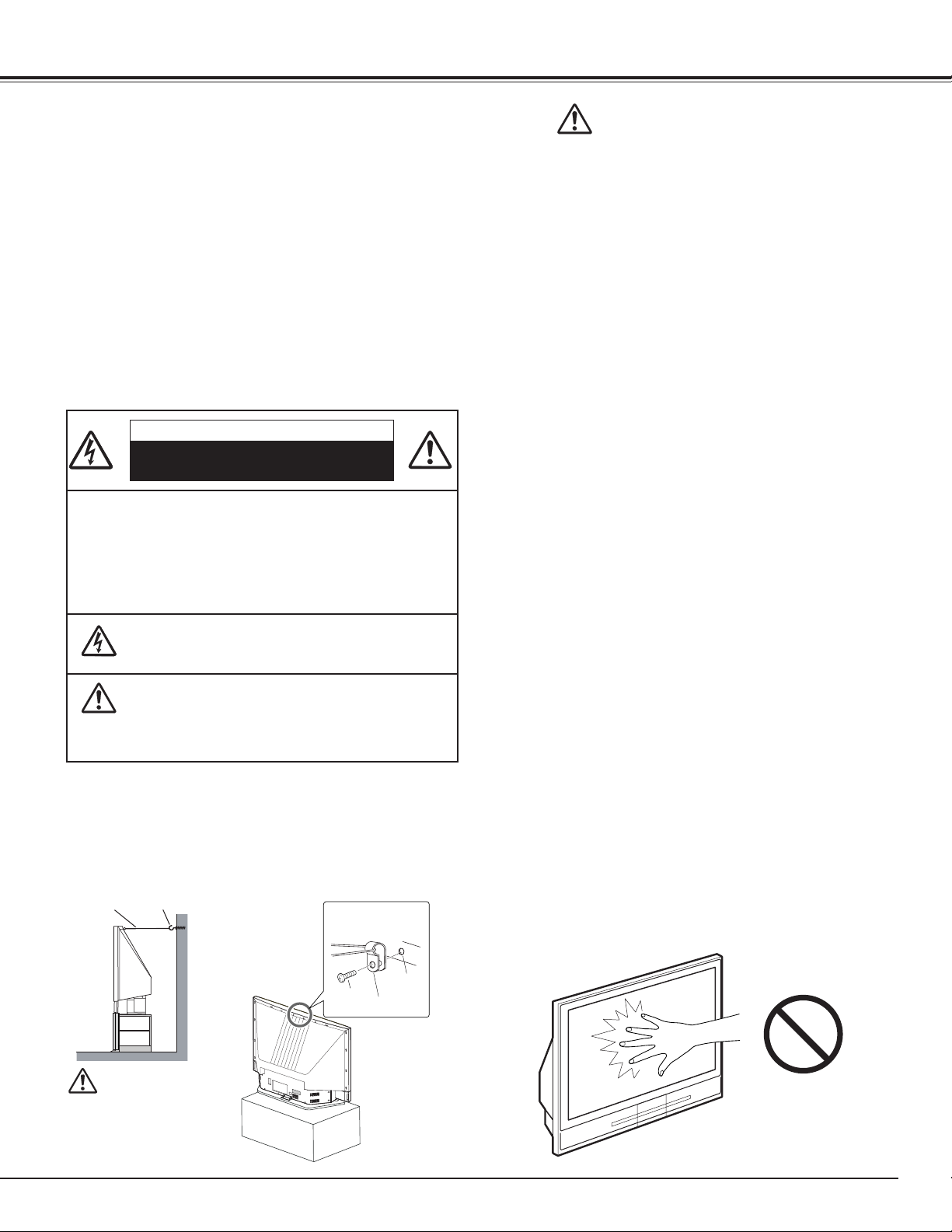
Care for Using the LCD Projection Monitor
When using the LCD Projection Monitor, the following
precautions should be taken. Otherwise, the screen can be
damaged:
●
Do not push or hit the screen surface.
●
Do not write, paint or affix anything on the screen.
●
Do not put anything on the LCD Projection Monitor.
For cleaning the LCD Projection Monitor, refer to "Cleaning the
LCD Projection Monitor" on p46 and maintain it properly.
NOTE:
● Black dots or bright points of light (red, green, or blue) may appear on the
screen. This is a characteristic of the LCD panels, not a malfunction of the
LCD Projection Monitor.
Do not push or hit
the screen.
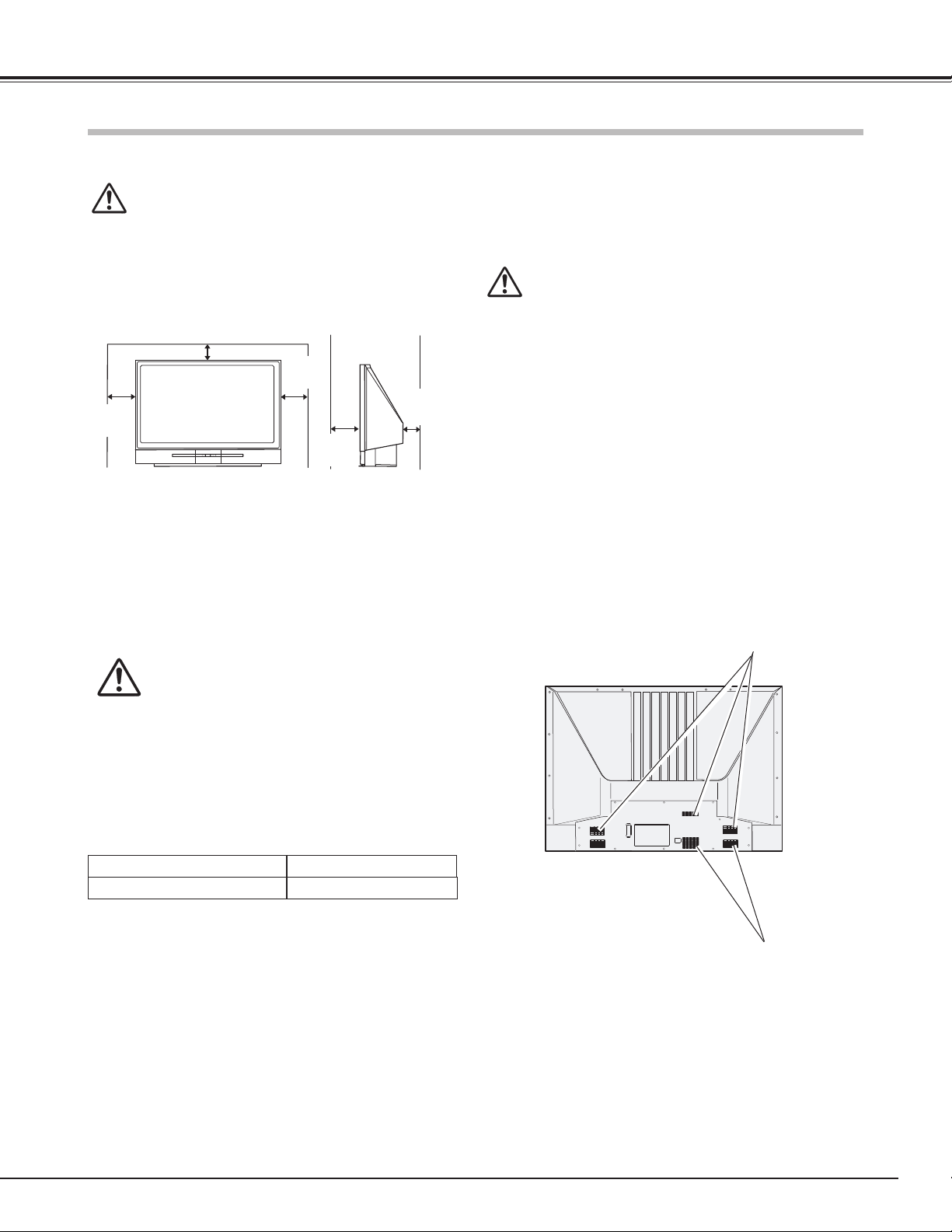
Installing the LCD Projection Monitor Safely
When installing the LCD Projection Monitor, secure the
Projection Monitor on the wall with safety parts (included)
with hook and a chain or wire. If not, the LCD Projection
Monitor may fall down and accident can result.
Attach the holder on
the back of the LCD
Projection Monitor
with a screw. Then
secure the holder
on the wall with a
commercially available chain or wire
and a hook.
Attaching the
safety parts
Hook
Chain, wire and hook
must sustain load of
33 lb (15kg).
Chain and wire
should be stretched
tight.
Chain or Wire
Secure with a chain
or wire (not supplied)
Screw
Screw
hole
Holder
Page 4
4
Safety Instructions
All the safety and operating instructions should be read before
the product is operated.
Read all of the instructions given here and retain them for later
use. Unplug this LCD Projection Monitor from AC power
supply before cleaning. Do not use liquid or aerosol cleaners.
Use a damp cloth for cleaning.
Follow all warnings and instructions marked on the LCD
Projection Monitor.
For added protection to the LCD Projection Monitor during a
lightning storm, or when it is left unattended and unused for
long periods of time, unplug it from the wall outlet. This will
prevent damage due to lightning and power line surges.
Do not expose this unit to rain or use near water... for
example, in a wet basement, near a swimming pool, etc...
Do not use attachments not recommended by the
manufacturer as they may cause hazards.
Do not place this LCD Projection Monitor on an unstable cart,
stand, or table. The LCD Projection Monitor may fall, causing
serious injury to a child or adult, and serious damage to the
LCD Projection Monitor. Use only with a cart or stand
recommended by the manufacturer, or sold with the LCD
Projection Monitor. Wall or shelf
mounting should follow the
manufacturer's instructions, and should
use a mounting kit approved by the
manufacturers.
An appliance and cart combination should
be moved with care. Quick stops,
excessive force, and uneven surfaces
may cause the appliance and cart combination to overturn.
Slots and openings on the back and bottom of the cabinet are
provided for ventilation, to insure reliable operation of the
equipment and to protect it from overheating.
The openings should never be covered with cloth or other
materials, and the bottom opening should not be blocked by
placing the LCD Projection Monitor on a rug, or other similar
surface. This LCD Projection Monitor should never be placed
near or over a radiator or heat register.
This LCD Projection Monitor should not be placed in a built-in
installation such as a book case unless proper ventilation is
provided.
Never push objects of any kind into this LCD Projection
Monitor through cabinet slots as they may touch dangerous
voltage points or short out parts that could result in a fire or
electric shock. Never spill liquid of any kind on the LCD
Projection Monitor.
Do not place items such as vases containing liquid on top of
the LCD Projection Monitor.
Do not install the LCD Projection Monitor near the ventilation
duct of air-conditioning equipment.
This LCD Projection Monitor should be operated only from the
type of power source indicated on the marking label. If you
are not sure of the type of power supplied, consult your
authorized dealer or local power company.
Do not overload wall outlets and extension cords as this can
result in fire or electric shock. Do not allow anything to rest
on the power cord. Do not locate this LCD Projection Monitor
where the cord may be damaged by persons walking on it.
Do not attempt to service this LCD Projection Monitor
yourself as opening or removing covers may expose you to
dangerous voltage or other hazards. Refer all servicing to
qualified service personnel.
Unplug this LCD Projection Monitor from wall outlet and refer
servicing to qualified service personnel under the following
conditions:
a. When the power cord or plug is damaged or frayed.
b. If liquid has been spilled into the LCD Projection Monitor.
c. If the LCD Projection Monitor has been exposed to rain or
water.
d. If the LCD Projection Monitor does not operate normally by
following the operating instructions. Adjust only those
controls that are covered by the operating instructions as
improper adjustment of other controls may result in
damage and will often require extensive work by a qualified
technician to restore the LCD Projection Monitor to normal
operation.
e. If the LCD Projection Monitor has been dropped or the
cabinet has been damaged.
f. When the LCD Projection Monitor exhibits a distinct
change in performance-this indicates a need for service.
When replacement parts are required, be sure the service
technician has used replacement parts specified by the
manufacturer that have the same characteristics as the
original part. Unauthorized substitutions may result in fire,
electric shock, or injury to persons.
Upon completion of any service or repairs to this LCD
Projection Monitor, ask the service technician to perform
routine safety checks to determine that the LCD Projection
Monitor is in safe operating condition.
Voor de klanten in Nederland
Bij dit produkt zijn batterijen
geleverd.
Wanneer deze leeg zijn, moet u
ze niet weggooien maar
inleveren als KCA.
Page 5
5
Compliance
AC Power Cord for the United Kingdom :
This cord is already fitted with a moulded plug incorporating a fuse, the value of which is indicated on the pin face of the
plug. Should the fuse need to be replaced, an ASTA approved BS 1362 fuse must be used of the same rating, marked thus
. If the fuse cover is detachable, never use the plug with the cover omitted. If a replacement fuse cover is required,
ensure it is of the same colour as that visible on the pin face of the plug (i.e. red or orange). Fuse covers are available from
the Parts Department indicated in your User Instructions.
If the plug supplied is not suitable for your socket outlet, it should be cut off and destroyed.
The end of the flexible cord should be suitably prepared and the correct plug fitted. (See Over)
WARNING : A PLUG WITH BARED FLEXIBLE CORD IS HAZARDOUS IF ENGAGED IN A LIVE SOCKET
OUTLET.
The Wires in this mains lead are coloured in accordance with the following code:
Green-and-yellow ············ Earth
Blue ································· Neutral
Brown ······························ Live
As the colours of the wires in the mains lead of this apparatus may not correspond with the coloured markings identifying
the terminals in your plug proceed as follows:
The wire which is coloured green-and-yellow must be connected to the terminal in the plug which is marked by the letter E
or by the safety earth symbol or coloured green or green-and-yellow.
The wire which is coloured blue must be connected to the terminal which is marked with the letter N or coloured black.
The wire which is coloured brown must be connected to the terminal which is marked with the letter L or coloured red.
WARNING : THIS APPARATUS MUST BE EARTHED.
The AC Power Cord supplied with this monitor meets the requirement for use in the country you purchased it.
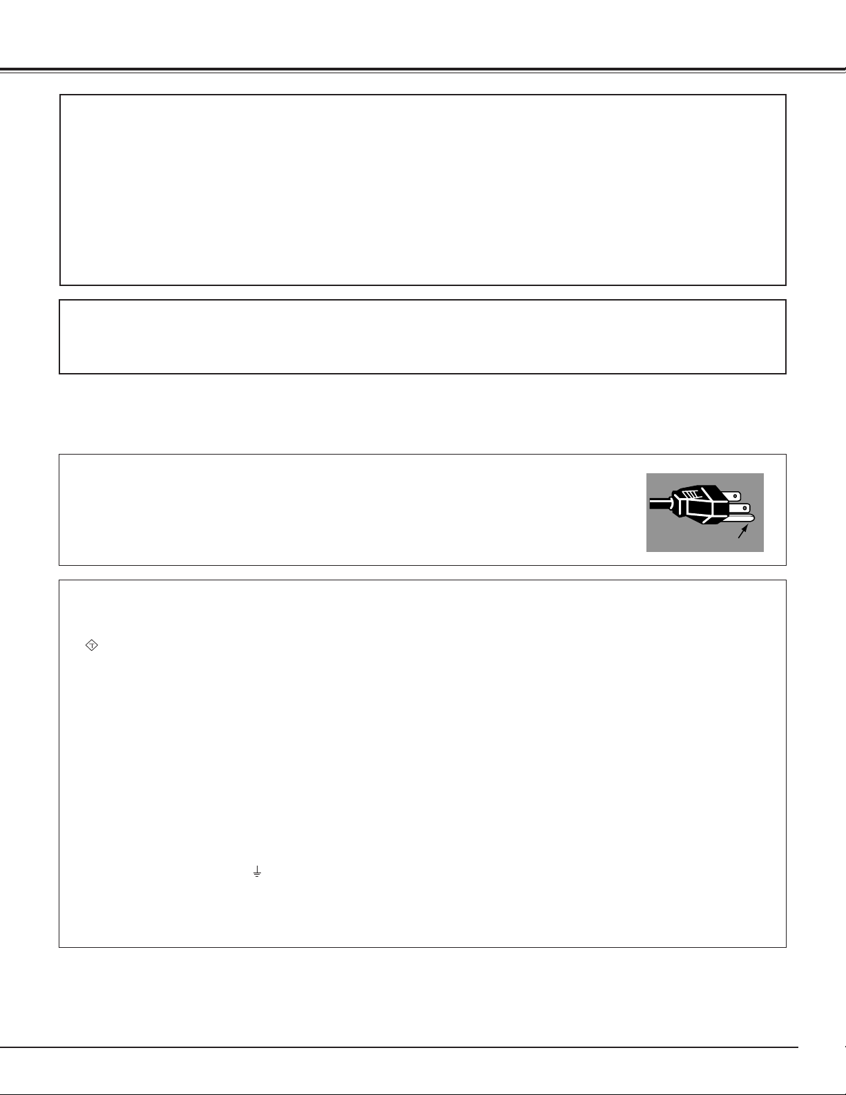
AC Power Cord for the United States and Canada :
AC Power Cord used in the United States and Canada is listed by the Underwriters Laboratories
(UL) and certified by the Canadian Standard Association (CSA).
AC Power Cord has a grounding-type AC line plug. This is a safety feature to be sure that the plug
will fit into the power outlet. Do not try to defeat this safety feature. Should you be unable to
insert the plug into the outlet, contact your electrician.
THE SOCKET-OUTLET SHOULD BE INSTALLED NEAR THE EQUIPMENT AND EASILY ACCESSIBLE.
AC POWER CORD REQUIREMENT
Federal Communication Commission Notice
This equipment has been tested and found to comply with the limits for a Class A digital device, pursuant to Part 15 of FCC
Rules. These limits are designed to provide reasonable protection against harmful interference when the equipment is
operated in a commercial environment. This equipment generates, uses, and can radiate radio frequency energy and, if not
installed and used in accordance with the instruction manual, may cause harmful interference to radio communications.
Operation of this equipment in a residential area is likely to cause harmful interference in which case the user will be
required to correct the interference at his own expense.
Do not make any changes or modifications to the equipment unless otherwise specified in the instructions. If such changes
or modifications should be made, you could be required to stop operation of the equipment.
CAUTION
This is a Class A equipment. This equipment can cause interference in residential areas; in this case, the operator can be
asked to take adequate countermeasures.
GROUND
ASA
Page 6

6
Features and Design
This LCD Projection Monitor is designed with the most advanced technology for various use. This LCD Projection Monitor
has a large screen and utilizes built-in multimedia features, a palette of 16.77 million colors, and matrix liquid crystal display
(LCD) technology.
◆ Compatibility
The LCD Projection Monitor widely accepts various
video and computer input signals including;
● Computers
IBM-compatible or Macintosh computer up to
1280 x 1024 resolution.
● 4 Color Systems
NTSC, PAL, SECAM, NTSC4.43 color system can
be connected.
● Component Video
Component video signal, such as a DVD player
output high definition TV signals including 480i,
480p, 575i, 575p, 720p, or 1080i, can be
connected.
● S-video
S-video signal, such as a S-VHS VCR output signal,
can be connected.
◆ Simple Computer System Setting
The LCD Projection Monitor has the Multi-scan system
to conform to almost all computer output signals quickly.
(p35.)
◆ High Quality Audio System
This LCD Projection Monitor has an audio system to
produce high quality sound. There are Bass, Treble and
Balance functions on the menu of the LCD Projection
Monitor so that you can enjoy powerful sound with the
large screen. (p24)
◆ Multi-language Menu Display
Operation menu is available in English, German, French,
Italian, Spanish, Portuguese, Dutch and Swedish. (p42.)
◆ Power Management
The Power management function reduces power
consumption and maintains the lamp life. (p43.)
◆ Digital Visual Interface
The LCD Projection Monitor is equipped with the DVI 24pin terminal for connecting DVI output from a computer
or video equipment. You can also enjoy digital
entertainment content protected by HDCP technology.
(See page 33 for HDCP.)
◆ Lamp Control
Brightness of the projection lamp can be changed by the
setting. The LCD Projection Monitor has the function to
adjust the brightness according to the input signal for
the best suited image. (p20, 44.)
◆ 16 : 9 Wide Screen
The LCD Projection Monitor employs 55" large-sized
screen and LCD panels (1280 x 720 resolution) of 16 : 9
ratio so that you can enjoy high quality image from the
computer in the full large screen.
◆ Active 3D Surround
This LCD Projection Monitor provides 3 dimentional
surround sound. (p19)
◆ No Operation Shut Off Timer
The LCD Projection Monitor can automatically be turned
off when no one operates the LCD Projection Monitor
over 3 hours. This function serves to maintain the lamp
life, save power and keep safety while you left the place
for a long time. (p42)
Page 7
7
Installing the LCD Projection Monitor
Openings on the cabinet are provided for ventilation, to
ensure reliable operation of the product and to protect it
from overheating. Therefore, these openings must not be
blocked or covered.
CAUTION
Hot air is exhausted from the exhaust vent. When using
or installing the LCD Projection Monitor, the following
precautions should be taken.
– Do not put any flammable objects near the vent.
– Keep the exhaust vent at least 0.3’(10cm) away from
any objects.
– Do not touch the peripheral part of the exhaust vent,
especially screws and metallic parts. These areas will
become hot while the LCD Projection Monitor is being
used.
Cooling fans are provided to cool down the LCD Projection
Monitor. This LCD Projection Monitor monitors internal
temperature and control the running speed of the cooling
fans.
Air Circulation
Installation
CAUTION
Never touch the Projection Screen directly with a hand.
It may effect the projection image quality.
Placing and Settling the LCD Projection Monitor
BE SURE TO USE OR PLACE THE LCD PROJECTION
MONITOR IN THE TEMPERATURE INDICATED
BELOW:
CAUTION
When placing the LCD Projection Monitor, the spaces for
ventilation must be maintained.
Place the LCD Projection Monitor on flat places or with an
exclusive LCD Projection Monitor stand. Placing on unflat
places may cause picture tilt or distortion.
Do not place the LCD Projection Monitor under the direct
sunlight. This may have a damaging effect on the picture
quality and the screen surface of the LCD Projection
Monitor.
41 ˚F ~ 95 ˚F (5 ˚C ~ 35 ˚C)
14 ˚F ~ 140 ˚F (-10˚C ~ 60 ˚C)
Operating Temperature
Storage Temperature
0.3'
(10cm)
0.6'
(20cm)
0.3'
(10cm)
Exhaust Vent
(Hot air exhaust)
Exhaust Vent
(Hot air exhaust)
0.6'
(20cm)
0.6'
(20cm)
Page 8
8
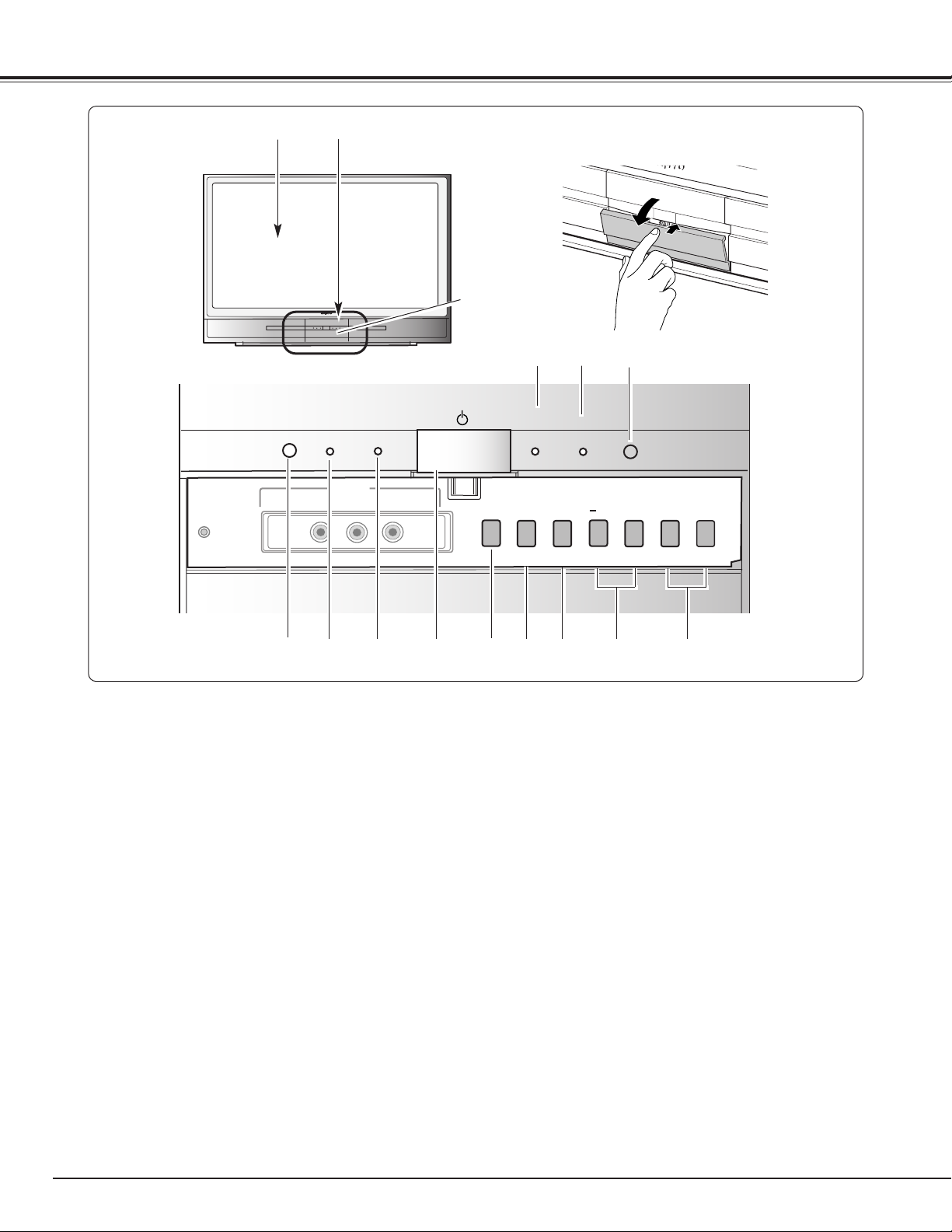
Front
!0 INPUT button
Used to select the input source. (p25, 26, 27, 33, 34)
o MENU button
Used to select the On-Screen Menu operation. (p21)
t Infrared Remote Receiver
!2
POWER indicator
It lights red when the LCD Projection Monitor is in the
stand-by mode. It remains green while the LCD
Projection Monitor is under operation. (p51)
y
Point (Up
ee
/Downdd) buttons
Used to select menus on the On-Screen Menu. (p21)
!3 ECO indicator
Emit yellow light when the Eco1 or Eco2 mode is
chosen in the Lamp control function. (p20, 44)
!1 POWER ON–OFF button
Used to turn the LCD Projection Monitor on or off. (p18)
r
q
e
w
t
u VOLUME +/- / Point (Left
77
/Right
88
) buttons
Used to adjust the volume or set and adjust the menu
data on On-Screen Menu. (p19, 21)
!1
q Projection Screen
w Front Panel and Indicators
e LAMP REPLACE indicator
Turn orange when the life of the projection lamp draws
to an end. (p47, 51)
io!0 u y
!2!3
i SELECT button
Used to execute the item selected and expand the
image in the Digital zoom mode. (p41)
r WARNING indicator
Emit red light when the LCD Projection Monitor detects
abnormal condition. This also blinks red when the
internal temperature of the LCD Projection Monitor
exceeds the operating range. (p45, 51)
!4
!4 Light Sensor
Detect the ambient light to adjust the display brightness.
(p20, 44)
Press here to open the Front
Cover and then the Front
control and terminals appear
as below.
Part Names and Functions
RESET
(VIDEO CONFERENCE)
VIDEO
ECO
INPUT 5
(MONO)
POWER
L–AUDIO–R
LAMP
WARNING
REPLACE
INPUT
MENU
SELECT
VOLUME
7
+
e
d
8
Page 9
9
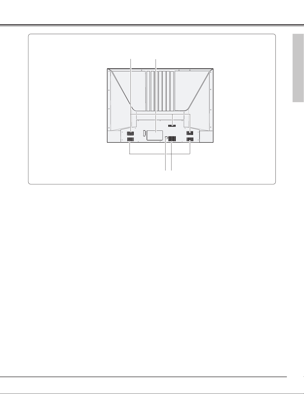
Part Names and Functions
NOTE:
● This LCD Projection Monitor detects internal temperature and
automatically controls the running speed of the cooling fans.
q Exhaust Vent
Back
w Terminals and Connectors (p11)
q w
q
e Power Cord Connector
e
Part Names and Functions
Page 10
10
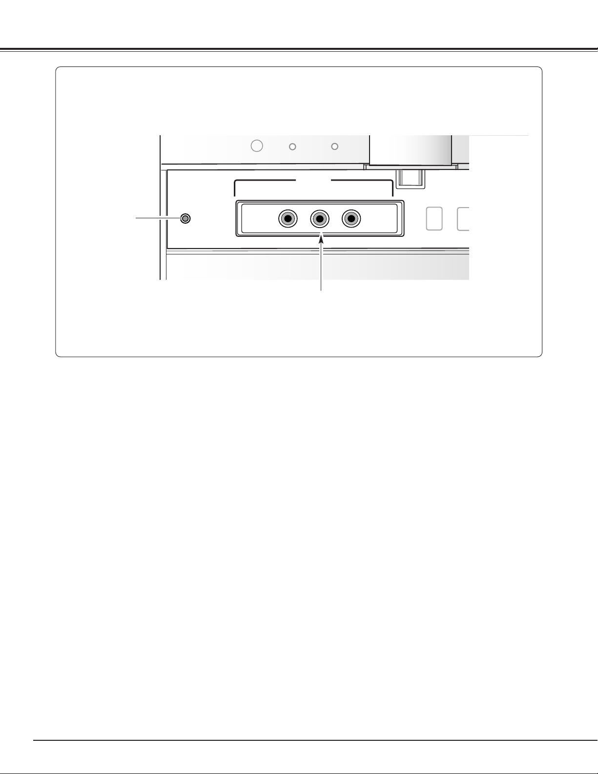
Part Names and Functions
7
q
*
RESET
A built-in micro processor which controls this unit may
occasionally malfunction and need to be reset. This can
be done by pressing the RESET button with a pen, which
will shut down and restart the unit. Do not use the
RESET function excessively.
*
Front Jacks
q Input 5
Connect video and audio output from video equipment to
these jacks. (p17)
● VIDEO (VIDEO CONFERENCE) (RCA-type)
● AUDIO L (MONO) and R (RCA-type)
(VIDEO CONFERENCE)
RESET
VIDEO
INPUT 5
(MONO)
L–AUDIO–R
INPUT
MENU
OK
Page 11
11
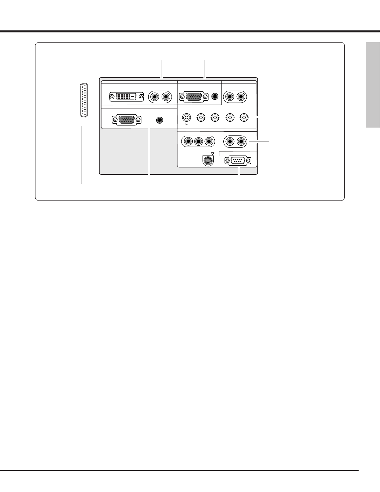
Part Names and Functions
q INPUT 1
Connect computer (Digital DVI-D type) and audio outputs
to these terminals. (p16, 17)
● RGB (PC DIGITAL / AV HDCP) (DVI-D)
● AUDIO R and L (MONO) (RCA-type)
Rear Terminals
q
w
e
t
r
y
y OUTPUT
Connect another monitor or external audio amplifier to
these jacks. (p16, 17)
● RGB ANALOG (D-SUB)
OUTPUT (ANALOG) terminal outputs the signals only
coming from INPUT 2 (ANALOG) and INPUT 3
(ANALOG RGB).
● AUDIO (Stereo)
Output Audio input of INPUT 1-5.
r INPUT 4
Connect component / video, s-video, and audio outputs
from video equipment to these jacks. (p16, 17)
● VIDEO (VIDEO CONFERENCE) / COMPONENT
(RCA-type)
● S-VIDEO (Mini DIN 4-type)
● AUDIO R and L(MONO) (RCA-type)
e INPUT 3
Connect RGB / component / video and audio outputs
from video equipment to these jacks. (p16, 17)
● RGB/ VIDEO (VIDEO CONFERENCE) / COMPONENT
(BNC-type)
● AUDIO R and L (MONO) (RCA-type)
w INPUT 2
Connect computer and audio outputs from computer to
these terminals. (p16)
● RGB ANALOG (D-SUB)
● AUDIO (Stereo) (Mini-type)
t SERIAL PORT
This jack is used to service this LCD Projection Monitor.
Part Names and Functions
u
u PJ Net Organizer Connector
This terminal is used for optional part, PJ Net Organizer.
For details, contact the dealer.
INPUT 1
DIGITAL(DVI-D)
ANALOG
R–AUDIO–L
OUTPUT
AUDI O
(MONO)
INPUT 2
ANALOG
Y – Pb/Cb – Pr/Cr
VIDEO (VIDEO CONFERENCE)
Y – Pb/Cb – Pr/Cr
AUDI O
RBG
INPUT 4
INPUT 3
R–AUDIO–L
H/V
R–AUDIO–L
(MONO)
V
(MONO)
VIDEO (VIDEO CONFERENCE)
S-VIDEO
SERIAL PORT
Page 12
12
Part Names and Functions
q
w
e
t
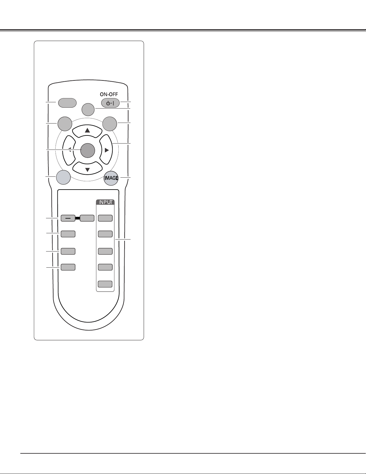
!4 AUTO PC button
Operate the Auto PC adjustment function. (p36)
r Point (Up
ee
/ Downdd/ Left7/ Right8) buttons
Select the item or adjust the value in the On-Screen Menu. These are also
used to pan the image in the Digital zoom mode. (p41)
!3 MENU button
Open or close the On-Screen Menu. (p21)
q POWER ON-OFF button
Turn the LCD Projection Monitor on or off. (p18)
w LAMP CONTROL button
Select the lamp mode. (p20, 44)
u SURROUND button
Turn the 3D Surround function on or off. (p19)
!1 FREEZE button
Freeze the projected image. (p20)
o MUTE button
Mute the sound. (p19)
r
y
u
i
o
!0
!1
!2
!3
!4
!0 VOLUME+/– buttons
Adjust the volume +/–. (p19)
e SCREEN button
Select the screen size. (p32, 41)
t IMAGE button
Selects the Image Level. (p29, 39)
y INPUT buttons
Select the input source. (p25, 26, 27, 33, 34)
!2 SELECT button
Execute the item selected, and expand the image in the Digital zoom mode.
(p41)
i AUDIO SELECT button
Select the sound qualities suitable for the projected program. (p19)
Remote Control
LL
AUTO PC
MENU
FREEZE
VOLUME
MUTE
AUDIO-S
SURROUND
LAMP
CONTROL
LAMP
SELECT
+
SCREEN
INPUT 1
INPUT 2
INPUT 3
INPUT 4
INPUT 5
Page 13
13
Part Names and Functions
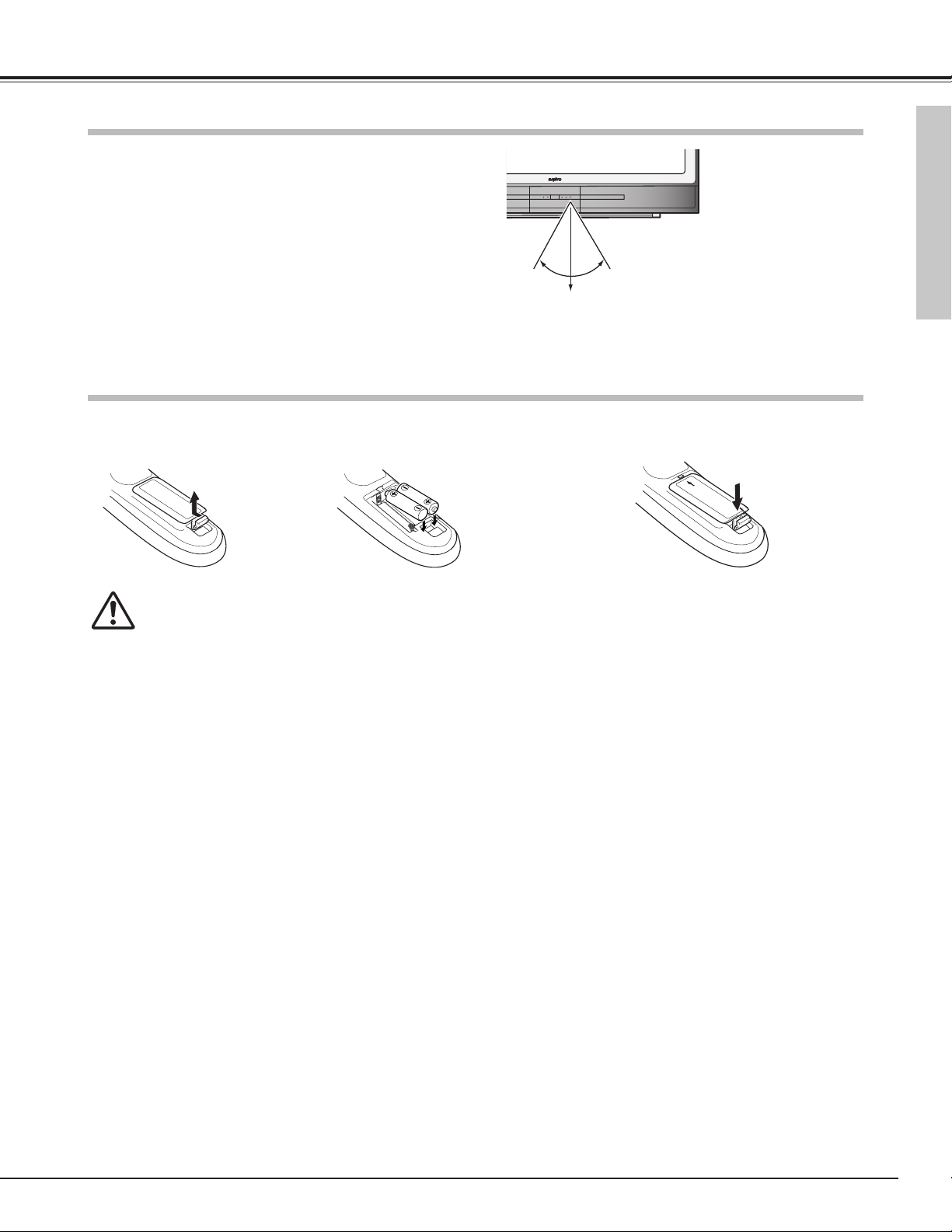
To insure safe operation, please observe the following precautions :
● Use two AA, UM3 or LR06 type alkaline manganese batteries.
● Replace two batteries at the same time.
● Do not use a new battery with a used battery.
● Avoid contact with water or liquid.
● Do not expose the remote control to moisture or heat.
● Do not drop the remote control.
● If a battery has leaked on the remote control, carefully wipe case clean and install new batteries.
● Risk of explosion if the battery is replaced by an incorrect type.
● Dispose of used batteries according to the instructions.
Pull up the lid
and remove it.
Remove the battery
compartment lid.
Slide the batteries
into compartment.
Replace the compartment lid.
Two AA size batteries
For correct polarity (+ and
–), be sure battery
terminals are in contact
with pins in compartment.
12 3
Part Names and Functions
Remote Control Batteries Installation
Point the remote control toward the LCD Projection Monitor
(Infrared Remote Receiver) whenever pressing any button.
Maximum operating range for the remote control is about 16.4’
(5m) and 60° in front of the LCD Projection Monitor.
Remote Control Operating Range
60°
16.4’ (5 m)
Page 14
14
Part Names and Functions
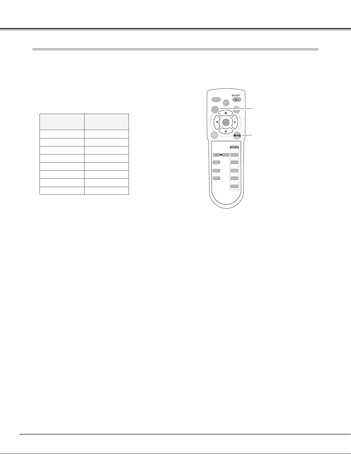
This LCD Projection Monitor has 8 different remote control codes (Code 1 - Code 8). Switching remote control codes
prevents remote control interference when operating several equipment at the same time. Change the remote control code
of the LCD Projection Monitor first before changing that of the remote control. See “Remote control” in the Setting on
page 43.
With holding down the MENU button, press the IMAGE button. The
code switches sequentially each time pressing the IMAGE button.
(See the list below.)
While pressing the MENU
button, press the IMAGE
button number of times
corresponding to the remote
control code.
MENU button
IMAGE button
Remote Control Code
Remote Control Code
Number of Times of
Pressing IMAGE Button
Code 1 1
Code 2 2
Code 3 3
Code 4 4
Code 5 5
Code 6 6
Code 7 7
Code 8 8
AUTO PC
MENU
LL
LAMP
CONTROL
LAMP
SCREEN
FREEZE
VOLUME
MUTE
AUDIO-S
SURROUND
SELECT
+
INPUT 1
INPUT 2
INPUT 3
INPUT 4
INPUT 5
Page 15
15
This LCD Projection Monitor uses nominal input voltages of 100120 V or 200-240 V AC. This LCD Projection Monitor automatically
selects the correct input voltage. It is designed to work with
single-phase power systems having a grounded neutral conductor.
To reduce the risk of an electrical shock, do not plug into any other
type of the power system.
Consult your authorized dealer or service station if you are not sure
of the type of power being supplied.
Connect the LCD Projection Monitor with all peripheral equipment
before turning the LCD Projection Monitor on. (See p16,17 for
connection.)
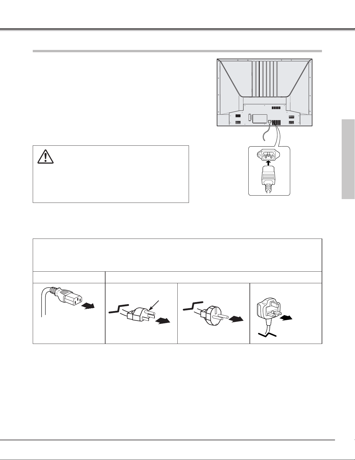
Connect the AC Power Cord (supplied) to the LCD
Projection Monitor. The AC outlet must be near this
equipment and must be easily accessible.
THE SOCKET-OUTLET SHOULD BE INSTALLED NEAR THE EQUIPMENT AND EASILY ACCESSIBLE.
CAUTION
For safety, unplug the AC power cord when the LCD Projection
Monitor is not in use.
When this LCD Projection Monitor is connected to the outlet
with the AC power cord, it is in stand-by mode and consumes a
little electric power.
Connecting the AC Power Cord
Preparation
NOTE ON THE POWER CORD
AC power cord must meet requirement of the country where you use a LCD Projection Monitor.
Confirm an AC plug type with the chart below and proper AC power cord must be used.
If supplied AC power cord does not match your AC outlet, contact your sales dealer.
To power cord connector
on your LCD Projection
Monitor.
LCD
Projection Monitor side
AC outlet side
Ground
To the AC outlet.
(120 V AC)
For Continental Europe
For the U.S.A. and Canada
For the U.K.
To the AC outlet.
(200 - 240 V AC)
To the AC outlet.
(200 - 240 V AC)
Preparation
Page 16
16
Preparation
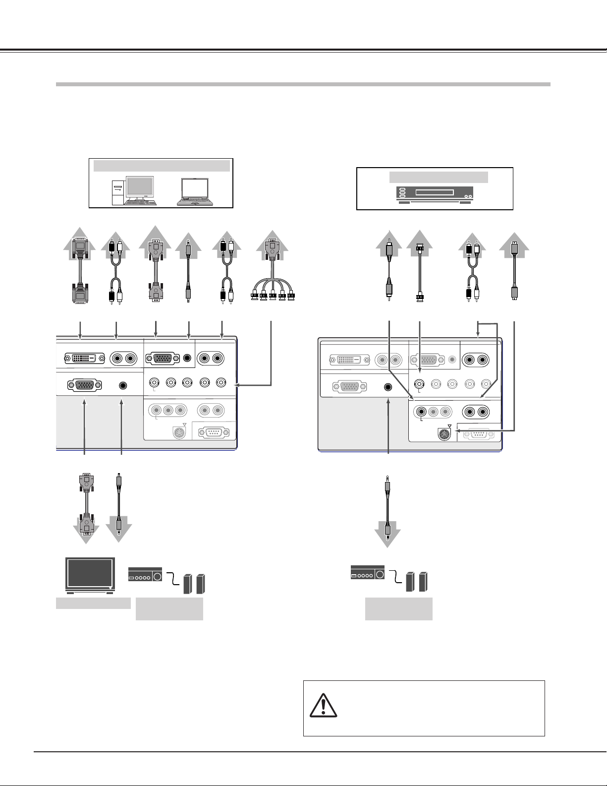
Connecting to a Computer and Video Equipment (Video, S-Video)
P8FK
Video Equipment
When connecting the cable, the power cords of both the LCD
Projection Monitor and the external equipment should be
disconnected from AC outlet.
Video Cable
(RCA x 1)
Video, S-Video
Use a Video cable or a S-Video cable (commercially
available).
NOTE:
● OUTPUT (ANALOG) terminal outputs the signals only coming from INPUT 2
(ANALOG) and INPUT 3 (ANALOG RGB).
● See p57 for ordering optional cables.
Audio Cable
(RCA x 2)
Audio
Output
S-VIDEO
S-video
Output
AUDIO
R/L(MONO)
P8FK
ANALOG RGB
DVI
Cable
IBM-compatible or Macintosh computer
Monitor Input
Computer (Digital/Analog)
Use a DVI cable (commercially available) for digital.
Use a VGA cable (Option) for analog.
Use a VGA-BNC cable (commercially available) for RGB.
VGA
Cable
DVI-D AUDIO
R/L(MONO)
Audio
Output
AUDIO
(Stereo)
Audio
Cable
(RCA x 2)
Audio Cable
(Mini Plug)
VGA
Cable
Audio Cable
(Mini Plug)
AUDIO
(Stereo)
ANALOG
RGB
Audio
Output
Audio Input
Monitor
Output
Monitor
Output
Video Output
S-Video
Cable
VIDEO
(VIDEO CONFERENCE)
External Audio
Equipment
External Monitor
Audio
Speaker
(stereo)
Audio Input
External Audio
Equipment
Audio
Speaker
(stereo)
Audio Cable
(Mini Plug)
AUDIO
(Stereo)
Monitor
Output
VGA-BNC
Cable
G, B, R, H/V, V
Audio
Cable
(RCA x 2)
Video
Cable
(BNC x 1)
AUDIO
R/L(MONO)
Audio
Output
INPUT 1
DIGITAL(DVI-D)
ANALOG
R–AUDIO–L
OUTPUT 1
(MONO)
AUDIO
INPUT 2
ANALOG
Y – Pb/Cb – Pr/Cr
VIDEO (VIDEO CONFERENCE)
Y – Pb/Cb – Pr/Cr
VIDEO (VIDEO CONFERENCE)
S-VIDEO
AUDIO
RBG
INPUT 4
INPUT 3
R–AUDIO–L
H/V
V
R–AUDIO–L
SERIAL PORT
(MONO)
(MONO)
INPUT 1
DIGITAL(DVI-D)
OUTPUT 1
ANALOG
INPUT 2
(MONO)
R–AUDIO–L
AUDIO
ANALOG
Y – Pb/Cb – Pr/Cr
VIDEO (VIDEO CONFERENCE)
Y – Pb/Cb – Pr/Cr
VIDEO (VIDEO CONFERENCE)
S-VIDEO
AUDIO
RBG
INPUT 4
INPUT 3
R–AUDIO–L
H/V
V
R–AUDIO–L
SERIAL PORT
(MONO)
(MONO)
Page 17
17
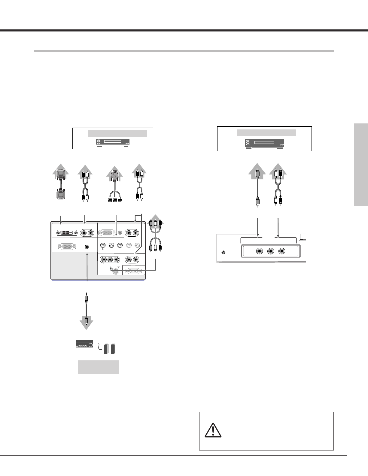
Preparation
P8FK
Video Equipment
Video/Component
Output
(Y, Pb/Cb, Pr/Cr)
Y-Pb/Cb-Pr/Cr
DVI-D
Audio Cable
(RCA x 2)
DVI
Cable
Component, DVI compatible with HDCP, Video
Use a DVI cable (commercially available) for DVI compatible with
HDCP.
Use a Component cable or VGA-BNC cable (commercially
available) for component.
Use a Video cable (commercially available) for component.
DVI Video
Output
VGA -BNC
Cable
Audio
Output
Audio Cable
(RCA x 2)
AUDIO
R/L(MONO)
Connecting to Video Equipment (Component, DVI compatible with HDCP)
Video Equipment
Video Output
VIDEO
(VIDEO
CONFERENCE)
Audio Cable
(RCA x 2)
AUDIO
R/L (MONO)
Audio
Output
Rear Terminals Front Terminals
NOTE:
● Digital RGB , Digital HDCP, Component and Video signal can not be output from the
OUTPUT terminal.
When connecting the cable, the power cords of both
the LCD Projection Monitor and the external equipment
should be disconnected from AC outlet.
Video
Cable
(RCA x 1)
Y-Pb/Cb-Pr/Cr
Audio
Output
AUDIO
R/L(MONO)
Audio Input
External Audio
Equipment
Audio
Speaker
(stereo)
Audio Cable
(Mini Plug)
AUDIO
(Stereo)
Preparation
Video
Use a Video cable (commercially available) for video.
Component
Cable
(RCA x 3)
R–AUDIO–L
AUDIO
(MONO)
AUDIO
RBG
INPUT 4
INPUT 3
R–AUDIO–L
H/V
R–AUDIO–L
SERIAL PORT
INPUT 2
ANALOG
Y – Pb/Cb – Pr/Cr
VIDEO (VIDEO CONFERENCE)
Y – Pb/Cb – Pr/Cr
VIDEO (VIDEO CONFERENCE)
S-VIDEO
(MONO)
V
(MONO)
RESET
(VIDEO CONFERENCE)
DIGITAL(DVI-D)
ANALOG
INPUT 1
OUTPUT 1
VIDEO
INPUT 5
(MONO)
L–AUDIO–R
Page 18
18
Tu r ning Off the LCD Projection Monitor
Tu r ning On the LCD Projection Monitor
Basic Operation
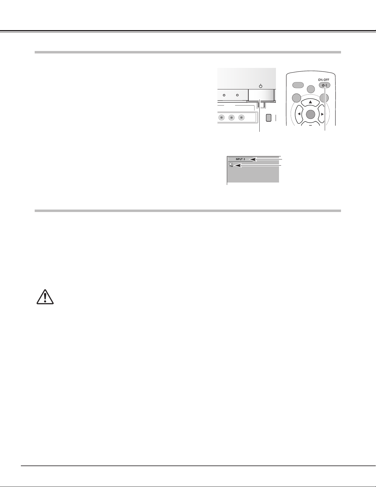
Press the POWER ON-OFF button on the front panel or on the remote
control.
The POWER indicator turns into orange, and it continues while the
cooling fans are operating (for about 4 minutes). The LCD Projection
Monitor can be turned on again during this period or after the indicator
turns into red.
When the LCD Projection Monitor has cooled down enough, the
POWER indicator emits red light. Then you can disconnect the AC
power cord.
TO MAINTAIN THE LIFE OF THE LAMP, ONCE YOU TURN
YOUR LCD PROJECTION MONITOR ON, WAIT AT LEAST
5 MINUTES BEFORE TURNING IT OFF.
DO NOT DISCONNECT AC POWER CORD WHILE
COOLING FANS ARE RUNNING OR BEFORE POWER
INDICATOR EMITS RED LIGHT. OTHERWISE IT WILL
RESULT IN SHORTENING LAMP LIFE.
NOTE:
● Do not use the LCD Projection Monitor for more than 24 hours continuously. Turn off the
LCD Projection Monitor at least once in 24 hours and give it a rest. Continuous use may
result in shortening the lamp life.
● This LCD Projection Monitor monitors internal temperature and automatically controls the
running speed of the cooling fans.
● If the WARNING indicator blinks or emits red light, see “Warning Indicator” on page 45,
51.
Press the POWER ON-OFF button on the front panel of the LCD
Projection Monitor or the remote control. The cooling fans start
to operate. The POWER indicator blinks green rapidly for 15
seconds.
2
3
1
The POWER indicator emits green light then the input source
and the lamp mode that were selected last will be displayed on
the screen.
Connect the LCD Projection Monitor's AC power cord into an
AC outlet and the POWER indicator turns into red.
Selected Input Source and Lamp Mode
Selected input source
M
V
R
Front Panel
NOTE:
● While the POWER indicator blinks green rapidly, no operation of the remote control and
the front panel can be accepted.
Selected lamp mode
Remote Control
POWER ON-OFF button POWER ON-OFF button
POWER
ECO
INPUT 5
ENCE)
(MONO)
IDEO
L–AUDIO–R
INPUT
LL
AUTO PC
MENU
LAMP
CONTROL
LAMP
SELECT
SCREEN
Page 19

19
Basic Operation
Volume
Press the VOLUME +/– button on the front panel or on the remote
control to adjust the volume. The volume dialog box appears on the
screen for a few seconds.
Press + button to turn up the volume and – button to turn it down.
Mute
Press the MUTE button on the remote control to minimize the sound.
To restore the sound to its previous level, press the MUTE button
again or press the VOLUME +/– button.
Direct Operation
Remote Control
Surround
Press the SURROUND button on the remote control to provide the 3D
surround (3 dimensional) sound.
Select the audio mode the most suitable for the projected program or
the input source among Music, Talk, Normal and Personal by pressing
the AUDIO-S button on the remote control.
FREEZE
AUDIO-S button
Remote Control
Music
Talk
AUDIO-S button
Normal
Personal
Bass sound fitting music programs.
Music
Treble sound fitting drama and news programs.
Talk
User preset sound. (p24)
Personal
Normal sound fitting any input source.
Normal
FREEZE
VOLUME
+/– button
MUTE button
SURROUND button
Audio Selection
Sound Adjustment
Basic Operation
Front Panel
VOLUME
+/– button
VOLUME
INPUT 1
+
MUTE
AUDIO-S
SURROUND
INPUT 2
INPUT 3
INPUT 4
INPUT 5
LAMP
WARNING
REPLACE
VOLUME
+
MENU
SELECT
7
8
e
d
VOLUME
+
MUTE
AUDIO-S
SURROUND
INPUT 1
INPUT 2
INPUT 3
INPUT 4
INPUT 5
Page 20

20
Basic Operation
Press the FREEZE button on the remote control to freeze the picture
on the screen. To cancel the Freeze function, press the FREEZE
button again or press any other button.
FREEZE
FREEZE button
Remote Control
Picture Freeze Function
Lamp mode can be selected from the following modes depending on
the program scenes and environments of using the LCD Projection
Monitor. The lamp mode can be selected in the Setting menu as
well. (p44)
Lamp Control Function
FREEZE
LAMP CONTROL
button
Remote Control
Display Icons:
Normal···· Normal brightness
Auto···· The controlled brightness according to the input
signal
Eco1····
The controlled brightness according to the ambient
light
Eco2···· 80% lower brightness than normal brightness and
reduce the lamp power consumption.
The ECO indicator emits yellow light when Eco1 or Eco2 is selected.
LL
LAMP
CONTROL
AUTO PC
LAMP
MENU
SELECT
FREEZE
MENU
SCREEN
SCREEN
FREEZE
VOLUME
SELECT
+
INPUT 1
Page 21

21
Basic Operation
Press the MENU button to display the On-Screen Menu
(Main menu).
Select a menu from the main menu by pressing the Point Up
/ Down button, and press the Point Right button to enter the
sub-menu. (The selected icon turns yellow.)
Press the MENU button to close the On-Screen Menu when
you are in the main menu. When you are in the sub-menu,
press the MENU button once to return to the main menu or
hold the MENU button for more than 2 seconds to close the
On-Screen Menu.
Select an item by pressing the Point Up / Down button, and
activate the item that you have selected with the
(SELECT), (Point Left),
or
(Point Right) button.
1
2
4
3
You can control and adjust this LCD Projection Monitor through
the On-Screen Menu. Refer to the following pages to operate
each adjustment on the On-Screen Menu.
I
Front Panel
Item
FREEZE
Remote Control
On-Screen Menu
On-Screen Menu (Main Menu)
NOTE:
● If you are selecting a sub-menu or an item displayed in a line, pressing the MENU
button takes you back to the previous On-Screen Menu.
● The On-Screen Menu disappears by holding down the MENU button for a while
whatever you are selecting.
On-Screen Menu (Sub-Menu)
Point buttons
SELECT button
MENU button
Basic Operation
SELECT button
Point buttons
MENU button
Point
Right
button
LL
LAMP
CONTROL
AUTO PC
LAMP
MENU
FREEZE
SCREEN
SELECT
LAMP
WARNING
REPLACE
NPUT
MENU
SELECT
VOLUME
7
+
e
d
8
Page 22

22
Basic Operation
Menus
VIDEO MENUS
Input Menu: select video input source. (p25-27)
AV System Menu: select video system from Auto, PAL, SECAM, NTSC4.43, NTSC, 1080i, 720p, 575p, 480p,
575i and 480i. (p28)
Image Select Menu: select image level from Standard, Cinema1, Cinema2, Game, Dynamic and Image.
(p29)
Image Adjust Menu: adjust Contrast, Brightness, Color, Tint, Color temp., White balance (R/G/B), Sharpness,
Gamma or Auto grayscale and use Reset or Store. (p30, 31)
Screen Menu: set the screen size from Full, Zoom, Caption in, Normal and Natural wide. (p32)
Audio Adjust Menu: adjust Treble, Bass or Balance and use Reset or Store. (p24)
Setting Menu: change various settings: Language, Blue back, Display, Background color, Menu position, No
operation shut off timer, Remote control, On start, Power management, Lamp control, Lamp
counter reset and Factory default. (p42-44)
Page 23

23
Basic Operation
COMPUTER MENUS
Input Menu: select computer input source. (p33-34)
PC System Menu: select computer system. (p35)
Image Select Menu: select image level from Standard, Real, Dynamic and Image. (p39)
Image Adjust Menu: adjust Contrast, Brightness, Color temp., White balance (R/G/B), Sharpness or Gamma
and use Reset or Store. (p40)
Screen Menu: set the screen size from Normal, Full, True and Digital zoom. (p41)
Setting Menu: change various settings: Language, Blue back, Display, Background color, Menu position, No
operation shut off timer, Remote control, On start, Power management, Lamp control, Lamp
counter reset and Factory default. (p42-44)
PC Adjust Menu: select Auto PC adj., Fine sync, Total dots, Horizontal, Vertical, Current mode, Clamp,
Display area, Display area H, Display area V, and use Reset, Mode free and Store. (p36-38)
Audio Adjust Menu: adjust Treble, Bass or Balance and use Reset or Store. (p24)
Basic Operation
Page 24

24
Basic Operation
Audio Adjustment
1
2
Select the Audio Adjustment menu with the Point Up / Down
button, and then press the Point Right button to enter the submenu.
Select an item with the Point Up / Down button and press the
Point Left / Right button to adjust the item.
Audio Adjust Menu
Menu Operation
Press the Point Left button to decrease high frequency sound, and
the Point Right button to increase high frequency sound. (From -30 to
+30)
Treble
Press the Point Left to decrease low frequency sound, and the Point
Right button to increase low frequency sound. (From -30 to +30)
Bass
Press the Point Left / Right button to adjust the balance of the left
and right speakers. (From L30 to R30)
Balance
Reset
Store
To store the adjusted data, select Store and press the Point Right
button. A confirmation box will appear and then select [Yes].
Stored data can be called up by selecting "Personal" in the Audio
Selection on page 19.
To reset the adjusted data, select Reset and press the Point Right
button. A confirmation box will appear and then select [Yes]. All
adjustments return to their previous figures.
The audio mode being selected
A confirmation box will appear
and select [Yes] and press the
SELECT button.
Press the Point Right button at
this icon to store the value.
Press the SELECT button or
the Point Up / Down button to
adjust the next item.
Press the MENU button to
return to the previous OnScreen Menu and store the
adjusted value.
Page 25

25
INPUT 1
INPUT 2
INPUT button
Input Source Selection (INPUT 3 / RGB, Video (Video conference), Component)
Direct Operation
FREEZE
+
Front Panel
Remote Control
INPUT button
O
Select INPUT 3 by pressing the INPUT 3 button on the remote control
or pressing the INPUT button on the front panel arbitrary number of
times.
Before using these buttons, correct input source should be selected
through menu operation as described below.
See p16-17 for the connection diagrams.
INPUT 3
INPUT 4
INPUT 5
INPUT 3 button
Select the Input Menu with the Point Up / Down button, and
then press the Point Right button to enter the sub-menu.
Select INPUT 3 with the Point Up / Down button and then press
the SELECT button or the Point Right button. The Source
Selection Menu will appear.
1
2
Move the pointer to the source that you want to select and then
press the SELECT button.
3
Menu Operation
Input Menu
Source Selection Menu
Closes the source selection
menu.
pointer
Video Input
Video Input
NOTE:
● Select RGB when the input source is analog coming from a computer through the R, G, B,
H/V, V jacks.
AUDIO–R
AUDIO-S
SURROUND
INPUT
INPUT 3
INPUT 4
INPUT 5
MENU
SELECT
V
7
Page 26

26
Video Input
Input Source Selection (INPUT 4 / Video (Video conference), S-video, Component)
Direct Operation
Select INPUT 4 by pressing the INPUT 4 button on the remote control
or pressing the INPUT button on the front panel arbitrary number of
times.
Before using these buttons, correct input source should be selected
through menu operation as described below.
See p16-17 for the connection diagrams.
Select the Input Menu with the Point Up / Down button, and
then press the Point Right button to enter the sub-menu.
Select INPUT 4 with the Point Up / Down button and then press
the SELECT button or the Point Right button. The Source
Selection Menu will appear.
1
2
Move the pointer to the source that you want to select and then
press the SELECT button.
When selecting AUTO, the LCD Projection Monitor
automatically selects the connected input source.
3
Menu Operation
Input Menu
Source Selection Menu
FREEZE
+
Remote Control
INPUT 4 button
INPUT 1
INPUT 2
INPUT buttonFront Panel
O
INPUT 3
INPUT 4
INPUT 5
INPUT button
Closes the source selection
menu.
pointer
NOTE:
● LCD Projection Monitor selects the input source in the
following priority.
1. Y, Pb/Cb, Pr/Cr
2. S-video
3. Video (Video conference)
AUDIO–R
AUDIO-S
SURROUND
INPUT
INPUT 3
INPUT 4
INPUT 5
MENU
SELECT
V
7
Page 27

27
Video Input
Input Source Selection (INPUT 5 / Video (Video conference) )
Direct Operation
Select INPUT 5 by pressing the INPUT 5 button on the remote control
or pressing the INPUT button on the front panel arbitrary number of
times.
See p17 for the connection diagrams.
Select the Input Menu with the Point Up / Down button, and
then press the Point Right button to enter the sub-menu.
Select INPUT 5 with the Point Up / Down button and then press
the SELECT button.
1
2
Menu Operation
Input Menu
FREEZE
+
Remote Control
INPUT 5 button
Video Input
INPUT 1
INPUT 2
INPUT buttonFront Panel
INPUT button
O
INPUT 3
INPUT 4
INPUT 5
AUDIO–R
AUDIO-S
SURROUND
INPUT
INPUT 3
INPUT 4
INPUT 5
MENU
SELECT
V
7
Page 28

28
Video Input
AV System Menu (Video or S-Video)
AV System Menu (Component)
Select the AV System Menu with the Point Up / Down button,
and then press the Point Right button to enter the sub-menu.
Choose the system that you want to select with the Point Up /
Down button and then press the SELECT button.
1
2
If the LCD Projection Monitor cannot reproduce proper video image, it
is necessary to select a specific video signal format among PAL,
SECAM, NTSC4.43 and NTSC.
PAL / SECAM / NTSC4.43 / NTSC
The LCD Projection Monitor automatically detects incoming
component video signal, and adjusts itself to optimize its
performance.
If the LCD Projection Monitor cannot reproduce proper video image, it
is necessary to select a specific component video signal format
among 480i, 575i, 480p, 575p, 720p, and 1080i.
Auto
Component Video Signal Format
Video or S-Video Input
Component Input
The LCD Projection Monitor automatically detects incoming video
system, and adjusts itself to optimize its performance.
Auto
Video System Selection
Menu Operation
Page 29

29
Video Input
Image Select Menu
Image Level Selection
FREEZE
Remote Control
IMAGE button
Select the Image Select Menu with the Point Up / Down button,
and then press the Point Right button to enter the sub-menu.
1
2
Choose the level that you want to select with the Point Up /
Down button and then press the SELECT button.
Normal picture level preset on this LCD Projection Monitor.
Standard
Picture level adjusted for the bright picture with fine tone.
Cinema1
Picture level suitable for projecting the picture in a bright room.
Dynamic
Select an image level among Standard, Cinema1, Cinema2, Game,
Dynamic,and Image by pressing the IMAGE button on the remote
control.
Normal picture level preset on this LCD Projection Monitor.
Standard
Picture level adjusted for the bright picture with fine tone.
Cinema1
Picture level suitable for projecting the picture in a bright room.
Dynamic
Direct Operation
Menu Operation
Picture level suitable for playing a game.
Game
Picture level suitable for playing a game.
Game
Picture level adjusted for the dark picture with fine tone.
Cinema2
User preset image in the Image Level Adjustment. (p30, 31)
Image
User preset image in the Image Level Adjustment. (p30, 31)
Image
Picture level adjusted for the dark picture with fine tone.
Cinema2
Video Input
SELECT
FREEZE
VOLUME
+
MUTE
INPUT 1
INPUT 2
Page 30

30
Video Input
Select the Image Adjust Menu with the Point Up / Down button,
and then press the Point Right button to enter the sub-menu.
1
2
Select an item with the Point Up / Down button and press the
Point Left / Right button to adjust the item.
Image Adjust Menu
Press the Point Left button to decrease contrast and the Point Right
button to increase contrast. (From -31 to +31)
Press the Point Left button to adjust image darker and the Point Right
button to adjust image brighter. (From -31 to +31)
Contrast
Brightness
This arrow indicates that there
are other items. Select this
item and press the Point Down
button to go to the next item.
Press the Point Left button to lighten color and the Point Right button
to deepen color. (From -31 to +31)
Press the Point Left / Right button to obtain proper color. (From -31 to
+31)
Color
Tint
Press the Point Left button to lighten red tone and the Point Right
button to deepen red tone. (From -31 to +31)
White balance (Red)
Press the Point Left button to lighten green tone and the Point Right
button to deepen green tone. (From -31 to +31)
White balance (Green)
Press the Point Left button to lighten blue tone and the Point Right
button to deepen blue tone. (From -31 to +31)
White balance (Blue)
NOTE
:
●
Tint cannot be selected when the video system is PAL or SECAM except for 575i.
Image Level Adjustment
Press the Point Left / Right button for Color temperature level that
you want to select. (Low3, Low2, Low1 Mid, High)
Color temp.
Press the SELECT button or
the Point Up / Down button to
adjust the next item.
Press the MENU button to
return to the previous OnScreen Menu and store the
adjusted value.
Go on to the next page...
The Image level being selected
(p29)
Page 31

31
Video Input
To store the adjusted data, select Store and press the Point Right
button. A confirmation box will appear and then select [Yes].
Stored data can be called up by selecting "Image" in the Image Level
Selection on page 29.
A confirmation box will appear
and select [Yes].
To reset the adjusted data, select Reset and press the Point Right
button. A confirmation box will appear and then select [Yes]. All
adjustments return to their previous figures.
Reset
Store
Press the Point Right button at
this icon to store the value.
Press the Point Left / Right button to obtain better balance of
contrast. (From -7 to +7)
Gamma
Press the Point Left button to soften the image and the Point Right
button to sharpen the image. (From -7 to +7)
Sharpness
Press the Point Left / Right button to switch On / Off. When this
function is "On", it automatically enhances contrast of bright and dark
part of image.
Auto grayscale
This arrow indicates that there
are previous items. Select this
item and press the Point Up
button to go to the previous
item.
NOTE:
● The adjusted parameters will be stored in "Image" on the Image Level Selection. (p29)
Video Input
Page 32

32
Video Input
Screen Size Adjustment
This LCD Projection Monitor has a useful function to resize a
projected screen.
Select the Screen Menu with the Point Up / Down button then
press the Point Right button to enter the sub-menu.
Select an item with the Point Up / Down button and press the
SELECT button to set the screen size.
1
2
Screen Menu
Provide an image to fit the width of the screen by expanding the
width of the image uniformly. This function can be used to project a
squeezed video signal at a wide video aspect ratio of 16 : 9.
When your video equipment (such as DVD) has 16 : 9 output mode,
select 16 : 9 and select Full in this Screen Menu to provide better
quality.
Full
NOTE:
● Screen Menu cannot be selected when 720p or 1080i is selected in the Video System
Selection (p28).
Provide an image to fit the screen size (16 : 9 aspect ratio) by
expanding the width and height of the image uniformly. This function
can be used to project a letter box mode picture (4 : 3 aspect picture
with black bar on the top and bottom edges) at a wide video aspect
ratio of 16 : 9.
Zoom
Provide an image including a caption to fit the screen size (16 : 9
aspect ratio) by expanding the width and height of the image
uniformly.
Caption in
Modify an image of 4 : 3 aspect ratio to fit the screen size (16 : 9
aspect ratio). It expands the width and height of the image and
makes it look natural.
Natural wide
Provide an image at a normal video aspect ratio of 4 : 3.
Normal
Full
Zoom
Normal
Natural wide
Caption in
Remote Control
SCREEN button
You can resize a projected screen with the SCREEN button on the
remote control.
Direct Operation
Menu Operation
LL
LAMP
CONTROL
AUTO PC
LAMP
MENU
SELECT
SCREEN
Racing is stimulating!
Racing is stimulating!
Page 33

33
Input Source Selection (INPUT 1 / PC digital, AV HDCP)
Direct Operation
Select INPUT 1 by pressing the INPUT 1 button on the remote control
or pressing the INPUT button on the front panel arbitrary number of
times.
Before using these buttons, correct input source should be selected
through menu operation as described below.
See p16-17 for the connection diagrams.
Select the Input Menu with the Point Up / Down button, and
then press the Point Right button to enter the sub-menu.
Select INPUT 1 with the Point Up / Down button and then press
the SELECT button or the Point Right button. The Source
Selection Menu will appear.
1
2
Move the pointer to the source that you want to select and then
press the SELECT button.
3
Menu Operation
Input Menu
Source Selection Menu
Close the Source Selection
Menu.
pointer
Computer Input
NOTE:
● HDCP (High-bandwidth Digital Content Protection) is a system for protecting digital
entertainment content delivered by DVI (Digital Visual Interface) from being copied.
The specification of HDCP is decided and controlled by Digital Content Protection, LLC.
Should the specification be changed, this LCD Projection Monitor may not display the
digital content protected by HDCP.
FREEZE
Remote Control
INPUT 1 button
Computer Input
INPUT 1
INPUT 2
INPUT buttonFront Panel
INPUT button
O
INPUT 3
INPUT 4
INPUT 5
AUDIO–R
VOLUME
MUTE
AUDIO-S
SURROUND
INPUT
INPUT 1
+
INPUT 2
INPUT 3
INPUT 4
INPUT 5
MENU
SELECT
V
7
Page 34

34
Computer Input
Input Source Selection (INPUT 2 / PC analog)
Direct Operation
Select INPUT 2 by pressing the INPUT 2 button on the remote control
or pressing the INPUT button on the front panel arbitrary number of
times.
See p16 for the connection diagrams.
Select the Input Menu with the Point Up / Down button, and
then press the Point Right button to enter the sub-menu.
Select INPUT 2 with the Point Up / Down button and then press
the SELECT button.
1
2
Menu Operation
Input Menu
FREEZE
+
MUTE
Remote Control
INPUT 2 button
INPUT 1
INPUT 2
INPUT buttonFront Panel
O
INPUT 3
INPUT 4
INPUT 5
INPUT button
AUDIO–R
INPUT
INPUT 2
AUDIO-S
SURROUND
INPUT 3
INPUT 4
INPUT 5
MENU
SELECT
V
7
Page 35

35
Computer Input
This LCD Projection Monitor can detect most of the current computer systems with the Multi-scan system and the Auto PC
adjustment function provided in the LCD Projection Monitor. When selecting computer input, the LCD Projection Monitor
automatically displays the most proper image for the input signal. One of the following four displays appears on the system
menu icon. If the LCD Projection Monitor does not tune the input signal and the projected image is not displayed properly,
or when you wish to adjust it manually, perform manual adjustment as described on page 37-38.
When the LCD Projection Monitor cannot recognize the
connected signal as PC system provided in this LCD
Projection Monitor, the Auto PC Adjustment function
operates to adjust the LCD Projection Monitor and the
message “Auto” is displayed in the PC System Menu
icon. When the image is not provided properly, manual
adjustment is required. (p37-38)
There is no signal input from the connected computer.
Check the connection of the computer and see if the
LCD Projection Monitor is set correctly.
(See “Troubleshooting” on page 50.)
Auto
– – – –
Computer System Menu
Select the Computer System Menu with the Point Up / Down
button, and then press the Point Right button to enter the submenu.
Choose the system that you want to select with the Point Up /
Down button and then press the SELECT button.
1
2
Computer System Menu
Computer system can also be selected manually if some Computer
systems appear on the On-Screen Menu.
User preset adjustment in Computer Adjustment.
Adjustment data can be stored in Mode 1 - 5. (p37-38)
Mode 1
Computer systems provided in the LCD Projection
Monitor. The LCD Projection Monitor chooses a proper
system and displays it.
SVGA 1
*Mode 1 and SVGA 1 are examples.
Computer System Selection
Menu Operation
Computer Input
PC System Menu Icon
Page 36

36
Computer Input
The Auto PC adjustment function is provided to automatically adjust Fine sync, Total dots, Horizontal, and Vertical to
conform to your computer. This function can be operated as follows.
Select the PC adjust Menu with the Point Up / Down button,
and then press the Point Right button to enter the sub-menu.
1
2
Choose the Auto PC adj. item and then press the SELECT
button.
PC Adjust Menu
Auto PC Adj.
To store adjustment data
Adjustment parameters from Auto PC adjustment can be memorized
in this LCD Projection Monitor. Once parameters are memorized, the
setting can be done just by selecting Mode in the Computer System
Selection. (p35) See “Store” on page 38.
NOTE
● The PC Adjust Menu cannot be operated when the input signal is digital or a signal
compatible with HDCP.
● The Auto PC adjust cannot be operated when 480i, 575i, 480p, 575p, 720p, or 1080i is
selected in the Computer System Selection. (p35)
Computer Adjustment (Auto)
Automatically adjusts Fine sync, Total dots, Horizontal, and Vertical for
the input signal from your computer.
This arrow indicates that there
are other items. Select this
item and press the Point Down
button to go to the next item.
Remote Control
AUTO PC button
The Auto PC adjustment function can be operated directly by pressing
the AUTO PC button on the remote control.
Direct Operation
Menu Operation
LL
LAMP
CONTROL
AUTO PC
LAMP
MENU
SELECT
SCREEN
Page 37

37
Computer Input
Some computers employ special signal formats which may not be tuned by Multi-scan system of this LCD Projection
Monitor. This LCD Projection Monitor has Manual PC Adjustment to enable you to precisely adjust several parameters to
match those signal formats. The LCD Projection Monitor has 5 independent memory areas to memorize those parameters
manually adjusted. This enables you to recall the setting for a specific computer whenever using it.
Select the PC Adjust Menu with the Point Up / Down button,
and then press the Point Right button to enter the sub-menu.
1
2
Select an item with the Point Up / Down button and press the
Point Left / Right button to adjust each item.
PC Adjust Menu
Adjust an image as necessary to eliminate flicker from the display.
Press the Point Left / Right button to adjust value. (From 0 to 31)
Fine sync
Adjust the number of total dots in one horizontal period. Press the
Point Left / Right button and adjust number to match your PC image.
Total dots
Adjust the horizontal picture position. Press the Point Left / Right
button to adjust the position.
Horizontal
Adjust the vertical picture position. Press the Point Left / Right button
to adjust the position.
Vertical
Press the Point Right button to show the information of the
connected computer.
Current mode
Adjust the clamp level. When the image has dark bars, try this
adjustment. Press the Point Left / Right button to adjust the clamp
level.
Clamp
Shows status
(Stored / Free) of the
selected Mode.
Selected Mode
Computer Adjustment (Manual)
Go on to the next page...
Press the SELECT button or
the Point Up / Down button to
adjust the next item.
Press the MENU button to
return to the previous OnScreen Menu and store the
adjusted value.
This arrow indicates that there
are other items. Select this
item and press the Point Down
button to go to the next item.
Computer Input
Page 38

38
Computer Input
Press the SELECT button to display the Display area dialog box.
Select the resolution at the Display area dialog box.
Display area
Adjust the horizontal area displayed by this LCD Projection Monitor.
Press the Point Left / Right button to decrease / increase value and
then press the SELECT button.
Display area H
Adjust the vertical area displayed by this LCD Projection Monitor.
Press the Point Left / Right button to decrease / increase value and
then press the SELECT button.
Display area V
Reset
Store
To store adjusted data, select Store and press the Point Right button.
The dialog box will appear and choose one of 5 modes and then press
the SELECT button.
To reset the adjusted data, select Reset and press the Point Right
button. A confirmation box will appear and then select [Yes]. All
adjustments return to their previous figures.
Mode free
Vacant Mode
Show the values of “Total
dots,” “Horizontal,” “Vertical,”
“Display area H,” and “Display
area V.”
Close this dialog box.
To store adjusted data
To clear adjusted data
To clear adjusted data previously set, select Mode free and press the
Point Right button. The dialog box will appear and choose one of 5
modes and then press the SELECT button.
This Mode has parameters being stored.
NOTE:
● Display area and Display area (H/V) cannot be selected when 480i, 575i, 480p, 575p,
720p, or 1080i is selected in the Computer System Selection. (p35)
Select Store to store the
adjusted data.
When selecting Display area,
this dialog box appears.
Page 39

39
Computer Input
Select an image level among Standard, Real, Dynamic, and Image by
pressing the IMAGE button on the remote control.
Normal picture level preset on this LCD Projection Monitor.
Picture level with improved halftone for graphics.
User preset image in the Image Level Adjustment. (p40)
Standard
Real
Image
Image Level Selection
Direct Operation
Menu Operation
Select the Image Select Menu with the Point Up / Down button,
and then press the Point Right button to enter the sub-menu.
1
2
Choose the level that you want to select with the Point Up /
Down button and then press the SELECT button.
Image Select Menu
Remote Control
Picture level suitable for projecting the picture in a bright room.
Dynamic
This check shows the level
being selected.
Normal picture level preset on this LCD Projection Monitor.
Standard
Picture level with improved halftone for graphics.
Real
Picture level suitable for projecting the picture in a bright room.
Dynamic
User preset image in the Image Level Adjustment. (p40)
Image
Computer Input
FREEZE
IMAGE button
SELECT
FREEZE
VOLUME
MUTE
INPUT 1
+
INPUT 2
Page 40

40
Computer Input
Image Level Adjustment
Select the Image Adjust Menu with the Point Up / Down button,
and then press the Point Right button to enter the sub-menu.
1
2
Select an item with the Point Up / Down button and press the
Point Left / Right button to adjust the item.
Press the Point Left button to decrease contrast and the Point Right
button to increase contrast. (From -31 to +31)
Press the Point Left button to adjust image darker and the Point Right
button to adjust image brighter. (From -31 to +31)
Contrast
Brightness
Press the Point Left / Right button to obtain better balance of
contrast. (From -7 to +7)
Gamma
Press the Point Left button to soften the image and the Point Right
button to sharpen the image. (From -7 to +7)
Sharpness
Press the Point Left button to lighten red tone and the Point Right
button to deepen red tone. (From -31 to +31)
White balance (Red)
Press the Point Left button to lighten green tone and the Point Right
button to deepen green tone. (From -31 to +31)
White balance (Green)
Press the Point Left button to lighten blue tone and the Point Right
button to deepen blue tone. (From -31 to +31)
White balance (Blue)
Press the Point Left / Right button for Color temperature level that
you want to select. (Low3, Low2, Low1 Mid, High)
Color temp.
To store the adjusted data, select Store and press the Point Right
button. A confirmation box will appear and select [Yes].
Stored data can be called up by selecting "Image" in the Image Level
Selection on page 39.
To reset the adjusted data, select Reset and press the Point Right
button. A confirmation box will appear and then select [Yes]. All
adjustments return to their previous figures.
Reset
Store
Image Adjust Menu
This arrow indicates that there
are other item menus.
Press the SELECT button or
the Point Up / Down button to
adjust the next item.
Press the MENU button to
return to the previous OnScreen Menu and store the
adjusted value.
A confirmation box will appear
and select [Yes].
Press the Point Right button at
this icon to store the value.
NOTE:
● The adjusted parameters will be stored in "Image" on the Image Level Selection. (p39)
The Image level being selected
(p39)
Page 41

41
Computer Input
This LCD Projection Monitor has a useful function to resize a projected screen.
When Digital zoom is selected, the On-Screen Menu disappears and
the message “D.zoom” is displayed. Press the SELECT button to
expand the image. And press the Point
eedd
7 8 buttons to pan the
image. The panning function can work only when the original image
is larger than screen size (1280 x 720).
Full
Digital zoom
NOTE:
● This Screen Menu cannot be operated when 720p(HDCP) is selected in the Computer
System Selection. (p35)
● The Normal and Digital zoom cannot be selected when 720p(HDTV) is selected in the
Computer System Selection. (p35)
● The True and Digital zoom cannot be selected when 480i, 575i, 480p, or 575p is
selected in the Computer System Selection. (p35)
● This LCD Projection Monitor cannot display any resolution higher than 1280 X 720. If
your computer’s screen resolution is higher than 1280 X 720, reset the resolution to the
lower before connecting to the LCD Projection Monitor.
● The image data in other than the resolution (1280 x 720) is modified to fit the screen
size in initial mode.
Provide image to fit screen size.
Normal
True
Screen Menu
Provide image in its original size. When the original image size is
larger than the screen size (1280 x 720), this LCD Projection Monitor
enters “Digital zoom” mode automatically.
Provide an image to fit the horizontal size of the screen.
Screen Size Adjustment
Select the Screen Menu with the Point Up / Down button, and
then press the Point Right button to enter the sub-menu.
Select an item with the Point Up / Down button and press the
SELECT button to set the screen size.
1
2
Remote Control
SCREEN button
You can resize a projected screen with the SCREEN button on the
remote control.
Direct Operation
Computer Input
To exit the Digital zoom mode, press the SCREEN button.
AUTO PC
MENU
LL
LAMP
CONTROL
LAMP
SCREEN
SELECT
Page 42

42
Language
The language used in the On-Screen Menu is available in English
German, French, Italian, Spanish, Portuguese, Dutch and Swedish.
Display
This function decides whether to display On-Screen Displays.
Press the Point Left / Right button to switch On / Off.
On ···· show all the On-Screen Displays.
Off ···· do not show On-Screen Displays except;
● On-Screen Menu
● “No signal” message
●”Please wait...!” message
Blue back
When this function is “On,” the LCD Projection Monitor projects a
blue image on screen while no input signal is detected.
Press the Point Left / Right button to switch On / Off.
Setting Menu (Language)
Setting
Menu position
Background color
This function is used to change the image of the On-Screen Menu
display
Menu position
This function is used to change the position of the On-Screen Menu.
Move it with the Point Up / Down / Left / Right button and press the
SELECT button to set it.
Select the Setting Menu with the Point Up / Down button, and
then press the Point Right button to enter the sub-menu.
Select an item with the Point Up / Down button to set various
settings.
1
2
After selecting a language,
move the pointer to this icon,
and press the SELECT button
to activate it.
This arrow indicates that there
are other items. Select this
item and press the Point Down
button to go to the next item.
No operation shut off timer
This function turns off the LCD Projection Monitor automatically when
there is no operation of the remote control or the front panel for 3
hours.
While this function is "On" and no operation continues for 3 hours, the
message "Set shut down" will be displayed for about 1 minute, and
the LCD Projection Monitor will shut off automatically.(in stand-by
mode)
Press the Point Left / Right button to switch On / Off.
Setting
Page 43

43
Setting
On start
When this function is “On”, the LCD Projection Monitor is
automatically turned on just by connecting the AC power cord to a
wall outlet. Press the Point Left / Right button to switch On / Off.
NOTE:
● When disconnecting the AC power cord without turning the LCD Projection Monitor off
and with On start function "On", next time the LCD Projection Monitor will be turned on
after completing the cool-down.
Remote control
This LCD Projection Monitor provides eight different remote control
codes (Code 1-Code 8); the factory-set, initial code (Code 1) and the
other seven codes (Code 2 to Code 8). This switching function
prevents remote control interference when operating several
equipment at the same time.
The same code should set on both the LCD Projection Monitor and
the remote control. For example, operating the LCD Projection
Monitor in “Code 7”,the remote control unit also must be switched to
“Code 7”.
To change the code for the LCD Projection Monitor;
Select a remote control code in this Setting Menu.
To change the code for the remote control;
While holding down the MENU button, press the IMAGE button
number of times corresponding to the remote control code for the
LCD Projection Monitor. (See page 14 for details.)
Remote control
Setting
Key lock
This function locks operation of the front controls and the remote
control. It is useful to prevent operation by a third person.
···· Unlocked.
···· Lock the operation of the front controls.
To unlock, use the remote control.
···· Lock the operation of the remote control.
To unlock, use the front controls.
··· Lock the operation of both the front controls and the
remote control.
To unlock, press the SELECT button on the front panel
for more than 20 seconds. The ECO indicator blinks
for 5 seconds and the lock will be released.
Select Key lock to
display this box.
Choose one of
these with the
Point e d buttons
and select [Yes] to
activate it.
Key lock
Page 44

44
Setting
This function is used to reset the Lamp replace counter. When
replacing the projection lamp, reset the Lamp replace counter by
using this function. See page 48 for operation.
Lamp counter reset
Factory default
This function returns all setting values except for the lamp counter to
the factory default settings.
Select Factory
default and this box
appears. Select
[Yes] , and the next
box appears.
Select [Yes] to
activate it.
Factory default
Lamp control
Lamp control
This function allows you to change brightness of the screen.
Auto···· the controlled brightness according to the input
signal
Eco1····
the controlled brightness according to the ambient
light
Eco2···· 80% lower brightness than normal brightness and
reduces the lamp power consumption.
Normal···· normal brightness
NOTE:
● You can also select a lamp mode with the LAMP CONTROL button on the remote
control. (p 20)
Press the Point Left / Right
button, to change the dialog
-
-
-
For reducing power consumption as well as maintaining the lamp life,
the Power management function turns off the projection lamp when
the input signal is interrupted and no button is pressed for a certain
period.
When the input signal is interrupted and no button is pressed for 30
seconds or more, the timer display with "No signal" message appears
on the screen to start the countdown.
The following operation differs according to the selected mode.
Ready . . . . . . . .When the count-down time has elapsed, the lamp
will be turned off and the POWER indicator slowly
blinks green. When any signal is connected or
any button on the remote control or the front
panel is pressed, the projection lamp will be
turned on again.
Shut down . . . . . When the count-down time has elapsed, the lamp
will be turned off and the POWER indicator emits
orange light. When the lamp has been fully
cooled down, the power will be turned off.
Off . . . . . . . . . . . Power management function is off.
Power management
Time left before lamp
will be off
Power management
Press Point Left / Right button,
to change the dialog Ready Shutdown - Off.
Timer can be adjusted with Point
Left / Right button between 1 to
30 Min.
This arrow indicates that there are previous
items. Select this item and press the Point
Up button to go to the previous item.
Page 45

45
The WARNING indicator shows the state of the function which protects the LCD Projection Monitor. Check the state of the
WARNING indicator and the POWER indicator to take proper maintenance.
WARNING
blinking red
Front Panel
Warning Indicator
The LCD Projection Monitor is shut down and the WARNING indicator is
blinking red
When the temperature inside the LCD Projection Monitor exceeds the
normal temperature, the LCD Projection Monitor is automatically shut
down to protect the LCD Projection Monitor. The POWER indicator is
blinking red and the LCD Projection Monitor is being cooled down.
When the temperature inside the LCD Projection Monitor returns to
normal, the POWER indicator emits red light and the LCD Projection
Monitor can be turned on.
NOTE:
● Even after the temperature inside the LCD Projection Monitor returns to normal, the
WARNING indicator may keep blinking. The WARNING indicator stops blinking when
the LCD Projection Monitor is turned on again.
Then check the items below.
✓ Did you provide appropriate space for the LCD Projection Monitor
to be ventilated? Check the installing condition to see if ventilation
slots are not blocked.
✓ Is the LCD Projection Monitor not installed near the ventilation duct
of air-conditioning equipment which may be hot? Install the LCD
Projection Monitor away from the ventilation duct of airconditioning equipment.
✓ Is the air filter clean? Clean the air filter or replace it with a new
one.
Front Panel
The LCD Projection Monitor is shut down and the WARNING indicator
emits red light
When the LCD Projection Monitor detects an abnormal condition, it is
automatically shut down to protect the inside and the WARNING
indicator emits red light. In this case, disconnect the AC power cord
and reconnect it, and then turn the LCD Projection Monitor on once
again for check. If the LCD Projection Monitor is turned off again and
the WARNING indicator emits red light, disconnect the AC power
cord and contact the service station for check and repair.
CAUTION
DO NOT LEAVE THE LCD PROJECTION MONITOR WITH
THE AC POWER CORD CONNECTED UNDER THE
ABNORMAL CONDITION. IT MAY RESULT IN FIRE OR
ELECTRIC SHOCK.
WARNING
emits red light
Maintenance and Cleaning
Maintenance and Cleaning
LAMP
REPLACE
WARNING
LAMP
WARNING
REPLACE
Page 46

46
Maintenance and Cleaning
RECOMMENDATION
We recommend avoiding dusty / smoky environments when
operating the LCD Projection Monitor. When using under dusty or
smoky conditions, dust may accumulate on the optical elements
inside the LCD Projection Monitor and the screen surface. This
condition may degrade the quality of a projected image.
When the above symptoms are noticed, contact your authorized
dealer or service station for proper cleaning.
Turn off the LCD Projection Monitor and disconnect the AC
power cord from the AC outlet.
1
2
The Air Filter prevents dust from accumulating on the optical elements inside the LCD Projection Monitor. Should the Air
Filter become clogged with dust particles, it will reduce the cooling fans' effectiveness and may result in internal heat
building up and effect on the life of the LCD Projection Monitor.
To clean the Air Filter, follow the cleaning procedures below:
Remove the Air Filter from the Air Filter Holder, and clean the
Air Filter with a brush or a vacuum cleaner.
If the Air Filter is clogged extremely or broken, replace it with a
new one.
3
Fit the Air Filter back in the Air Filter Holder and then replace it
to the LCD Projection Monitor. Make sure that the Air Filter fits
the place where it should be.
4
CAUTION
Do not operate the LCD Projection Monitor with the Air
Filter removed. The dust is stuck in the LCD Projection
Monitor and it may degrade the clear picture reproduction
performance.
Replace the right front cover to the LCD Projection Monitor.
5
Push downward with a forefinger on the Air Filter Holder and
pull the Air Filter Holder off the LCD Projection Monitor.
6
Remove the Right front cover of the LCD Projection Monitor.
a. Hold right upper side of the cover and slightly pull forward.
b. Hold both sides of the cover and remove it.
Right Front Cover
Air Filter Holder
Pull this
part first.
Air Filter Holder
Air Filter
Cleaning the LCD Projection Monitor
Be sure to disconnect the AC Power cord from the AC outlet before
cleaning the LCD Projection Monitor.
●
Gently wipe the screen and the cabinet with a soft dry clean cloth.
●
When it is heavily soiled, wipe the screen and the cabinet with a
soft cloth dampened with warm water and finish with a soft, dry
clean cloth.
CAUTION
DO NOT USE BENZENE, THINNER, OR ANY VOLATILE
SUBSTANCES TO CLEAN THE LCD PROJECTION
MONITOR. THESE CHEMICALS MAY CAUSE DAMAGE TO
THE PRODUCT.
Cleaning the Air Filter
Page 47

47
Maintenance and Cleaning
When the life of the projection lamp of this LCD Projection Monitor
draws to an end, the LAMP REPLACE indicator emits orange light. If
this indicator emits orange light, replace the lamp with a new one
promptly.
This indicator emits orange light
when the life of the projection
lamp draws to an end.
Front Panel
Lamp Replacement
Turn off the LCD Projection Monitor and disconnect the AC plug.
Allow the LCD Projection Monitor to cool for at least 30
minutes.
Loosen 4 screws that secure the Lamp Cover with a
screwdriver and remove the Lamp Cover.
1
3
Loosen the 2 screws that secure the lamp with a screwdriver
and pull out the Lamp by grasping the handle.
4
Replace the Lamp with a new one and tighten the 2 screws.
Make sure that the Lamp is correctly secured into the Lamp
compartment. Refer to p49 for ordering the replacement lamp.
5
Remove the Left front cover of the LCD Projection Monitor.
a. Hold left upper side of the cover and slightly pull forward.
b. Hold both sides of the cover and remove it.
2
Connect the AC Power Cord to the LCD Projection Monitor and
turn on the LCD Projection Monitor.
Follow these steps to replace the lamp assembly.
Put the Lamp Cover back and tighten the 4 screws and then
replace the Left front cover.
6
Reset the Lamp replace counter.
See “Lamp Replace Counter” on the next page .
For continued safety, replace with a lamp of the same
type. Do not drop the lamp or touch the glass bulb! The
glass can shatter and may cause injury.
Allow the LCD Projection Monitor to cool, for at least
30minutes before you open the Lamp cover. The inside
of the LCD Projection Monitor can become very hot.
CAUTIONCAUTION
CAUTION
When installing the new Lamp into the Lamp compartment, make
sure the Lamp socket is securely plugged into the compartment
socket. Improper or loosen socket connection may cause arc
discharge resulting fire hazard.
7
8
Left Front
Cover
Screws
Screws
Lamp Cover
Handle
Screws
Pull this
part first.
Maintenance and Cleaning
-OFF
REPLACE
LAMP
WARNING
Page 48

48
Maintenance and Cleaning
Be sure to reset the Lamp replace counter after the lamp is replaced. When the Lamp replace counter is reset, the LAMP
REPLACE indicator stops emitting.
Turn the LCD Projection Monitor on, press the MENU
button, and the On-Screen Menu will appear. Select the
Setting Menu with the Point Up / Down button and press the
Point Right button to enter the sub-menu.
Select the Lamp counter reset item and then press the
SELECT button. The message "Lamp replace counter reset?"
is displayed. Choose [Yes] and then press the SELECT
button.
1
2
Another confirmation dialog box appears and choose [Yes] to
reset the Lamp replace counter.
3
Lamp Replace Counter
NOTE:
● Do not reset the Lamp replace counter without implementation of lamp replacement.
Be sure to reset the Lamp replace counter only after replacing the lamp.
Lamp counter reset
Page 49

49
Maintenance and Cleaning
This LCD Projection Monitor uses a high-pressure lamp which must be handled carefully and properly.
Improper handling may result in accidents, injury, or create a fire hazard.
● Lamp lifetime may differ from lamp to lamp and according to the environment of use. There is no
guarantee of the same lifetime for each lamp. Some lamps may fail or terminate their lifetime in a
shorter period of time than other similar lamps.
● If the LCD Projection Monitor indicates that the lamp should be replaced, i.e., if the LAMP REPLACE
indicator lights up, replace the lamp with a new one IMMEDIATELY after the LCD Projection Monitor
has cooled down.
( Follow carefully the instructions in the Lamp Replacement section of this manual. ) Continuous use
of the lamp with the LAMP REPLACE indicator lighted may increase the risk of lamp explosion.
● A Lamp may explode as a result of vibration, shock or degradation as a result of hours of use as its
lifetime draws to an end. Risk of explosion may differ according to the environment or conditions in
which the LCD Projection Monitor and lamp are being used.
IF A LAMP EXPLODES, THE FOLLOWING SAFETY PRECAUTIONS SHOULD BE TAKEN.
If a lamp explodes, disconnect the LCD Projection Monitor’s AC plug from the AC outlet immediately.
Contact an authorized service station for a checkup of the unit and replacement of the lamp. Additionally,
check carefully to ensure that there are no broken shards or pieces of glass around the LCD Projection
Monitor or coming out from the cooling air circulation holes. Any broken shards found should be cleaned
up carefully. No one should check the inside of the LCD Projection Monitor except those who are
authorized trained technicians and who are familiar with LCD Projection Monitor service. Inappropriate
attempts to service the unit by anyone, especially those who are not appropriately trained to do so, may
result in an accident or injury caused by pieces of broken glass.
LAMP HANDLING PRECAUTIONS
ORDER REPLACEMENT LAMP
Replacement lamp can be ordered through your dealer. When ordering a projection lamp, give the following information
to the dealer.
● Model No. of your LCD Projection Monitor : PLV-55WM1
● Replacement Lamp Type No. : POA-LMP76A
(Service Parts No. 610 318 7266)
Maintenance and Cleaning
Page 50

50
WARNING :
High voltages are used to operate this LCD Projection Monitor. Do not attempt to open the
cabinet.
If problems still persist
after following all operating instructions,
contact the dealer where you purchased the LCD Projection
Monitor or the service center.
Give the model number and explain about the problem. We will advise you how to obtain
service.
The Remote Control
does not work.
–
Check the batteries. (p13)
–
Make sure no obstruction is between the LCD Projection Monitor and remote control.
–
Make sure you are not too far from the LCD Projection Monitor when using the remote
control. Maximum operating range is 16.4’ (5m). (p13)
–
Make sure the code of the remote control is conformed to that of the LCD projection
Monitor. (p14, 43)
– Check if the remote control is locked with Keylock function. (p43)
Tr oubleshooting
Before calling your dealer or service center for assistance, check the items below once again.
– Make sure you have properly connected the LCD Projection Monitor to peripheral equipment as described in “Connecting
to a Computer and Video Equipment” and "Connecting to Video Equipment" on page16 and 17.
– Make sure all equipment is connected to AC outlet and the power is turned on.
– When you operate the LCD Projection Monitor with a computer and it does not project an image, restart the computer.
No power
– Plug the power cord of the LCD Projection Monitor into the AC outlet.
– Check the WARNING indicator. If the WARNING indicator emits red light, the LCD
Projection Monitor cannot be turned on. (See "Warning Indicator" on page 45.)
– Check if the front controls and/or the remote control is locked with Keylock function.
(p43)
No sound
–
Check audio cable connection from audio input source.
–
Adjust the audio source.
–
Press the Vol + button.
–
Press the Mute button.
Problem:
–
Try these solutions.
Some displays are not
seen during the
operation.
–
Check the Display item. (See “Setting” on page 42.)
No image
–
Check the connection between video equipment or your computer and the LCD
Projection Monitor.
–
See if the input signal is correctly output from your computer. Some laptop computers
may need changing the setting for monitor output when you are connecting a laptop
computer. See your computer’s owner’s manual for setting.
–
It takes about 30 seconds to display an image after turning on the LCD Projection
Monitor.
–
See if the selected system is corresponding with video equipment or your computer.
–
Select correct input source once again through menu operation.
–
Make sure the temperature is not out of the operating temperature 41˚F ~ 95˚F (5 ˚C ~ 35
˚C).
Poor or dark image
–
Adjust Brightness in the Image Adjust menu.
–
Check the lamp mode. In Eco1 or Eco2 mode, the picture may become less brighter than
in Normal mode.
Appendix
Page 51

51
Appendix
Check the indicators for LCD Projection Monitor condition.
Indicators and Condition of the LCD Projection Monitor
The LCD Projection Monitor is OFF. (The AC power cord is unplugged.)
The temperature inside the LCD Projection Monitor is abnormally high. The
LCD Projection Monitor cannot be turned on. When the LCD Projection
Monitor
has cooled down enough and the temperature returns to normal,
the POWER indicator emits red light and the LCD Projection
Monitor
can be
turned on. (The WARNING indicator keeps blinking.) Check and clean the
Air Filter.
LCD Projection Monitor Condition
The LCD Projection
Monitor
is ready to be turned on with the POWER
ON-OFF button. The cooling fans are stopped.
POWER
red/green/
orange
Indicators
LAMP
REPLACE
orange
WARNING
red
The LCD Projection Monitor detects an abnormal condition and cannot be
turned on. Unplug the AC power cord and plug it again to turn on the LCD
Projection Monitor. If the LCD Projection Monitor is turned off again,
disconnect the AC power cord and contact the dealer or the service center
for service and checkup. Do not leave the LCD Projection Monitor on. It
may cause an electric shock or a fire hazard.
✽
✽
✽
✽
The LCD Projection Monitor is operating normally.
Blink slowly: The LCD Projection Monitor is in the Power management mode.
Blink rapidly: The LCD Projection Monitor is turned on from the stand-by
mode.
✽
✽
The LCD Projection Monitor has been cooled down enough and the
temperature returns to normal. When turning on the LCD Projection
Monitor, the WARNING indicator stops blinking. Check and clean the Air
Filter.
The LCD Projection Monitor can be turned on with the POWER ON-OFF
button. The cooling fans are running.
✽
✽ When the life of the projection lamp draws to an end, the LAMP REPLACE indicator emits orange light. When this indicator emits
orange light, replace the projection lamp with a new one promptly. Reset the Lamp replace counter after replacement of the lamp.
See page 47-48.
• • • emits green. • • • emits red. • • • off
• • • blinks green. • • • blinks red.
• • • emits orange.
Appendix
Page 52

52
Appendix
Menu Tree
Auto
PAL
SECAM
NTSC4.43
NTSC
Video Input
Auto
1080i
720p
575p
480p
575i
480i
-31 ~ +31
-31 ~ +31
-31 ~ +31
-31 ~ +31
System (2)
System (1)
Image Adjust
Contrast
Brightness
Color
Tint
Red
Green
Blue
Sharpness
Reset
Store
Gamma
-31 ~ +31
-31 ~ +31
-31 ~ +31
-7 ~ +7
-7 ~ +7
Yes / No
Yes / No
Low 3Color temp.
Low 2
Low 1
INPUT 2
Go to System (3)
Video / Computer Input
✽N/A - - - not applicable
RGB
Auto grayscale On / Off
High
Mid
INPUT 3
Go to System (1)
Go to System (2)
Go to System (3)
RGB
Y, Pb/Cb, Pr/Cr
INPUT 5
Go to System (2)
Go to System (1)
Y, Pb/Cb, Pr/Cr
INPUT 4
Go to System (1)
Go to System (1)
Go to System (1) or (2)
Auto
S - video
Standard
Cinema 1
Game
Image
Image Select
Cinema 2
Dynamic
Full
Caption in
Normal
Screen
Zoom
Natural wide
N/A
N/A
RGB(AV HDCP)
INPUT 1
RGB(PC digital)
Video (Video conference)
Video (Video conference)
Video (Video conference)
Input
Quit
Quit
Quit
Adj.
Page 53

53
Appendix
System (3)
Mode 1
Mode 2
SVGA 1
SVGA 3
Auto PC Adj.
Fine sync.
Total dots
Horizontal
Vertical
Clamp
Display area
Display area - H
Display area - V
Reset
Standard
Real
Dynamic
Contrast
Brightness
Color temp.
Red
Green
Blue
Gamma
Store
Normal
Full
True
Digital zoom
0 ~ 31
-31 ~ +31
-31 ~ +31
Computer Input
PC Adjust
640 x 480
720 x 400
800 x 600
1024 x 768
1152 x 864
1280 x 720
1280 x 1024
Image Select
Low 3
-31 ~ +31
-31 ~ +31
-31 ~ +31
-7 ~ +7
Yes / No
Screen
Quit
Yes / No
✽Systems displayed in the System Menu vary
depending on an input signal.
Low 2
Reset
Yes / No
Low 1
Mid
Sharpness -7 ~ +7
High
Image Adjust
- - - -
Image
Store Mode 1
Mode 2
Mode 3
Mode 4
Mode 5
Quit
Mode 1
Mode 2
Mode 3
Mode 4
Mode 5
Quit
Mode free
H-Sync.freq.
V-Sync.freq.
Quit
Current mode
Appendix
Page 54

54
Appendix
Setting
On / Off
On / Off
On / Off
Normal
Yes / No
Blue back
Display
No operation shut off timer
Lamp control
Factory default
Auto
Eco1
Yes / NoLamp counter reset
Background color
Menu Position
Eco2
Audio
Audio
Treble
Bass
Balance
Store Yes / No
Reset
Yes / No
-30 ~ +30
-30 ~ +30
L30 ~ R30
Power Management
Code 1 - 8 Remote control
On / OffOn start
English
German
French
Italian
Spanish
Portuguese
Dutch
Swedish
Quit
Setting
Language
Off
Ready
Shutdown
Timer(1-30 Min)
Quit
Video / Computer Input
Key lock
Page 55

55
Appendix
Compatible Computer Specifications
Basically this LCD Projection Monitor can accept the signal from all computers with the V, H-Frequency below mentioned and
less than 100 MHz of Dot Clock.
ON-SCREEN
DISPLAY
RESOLUTION
H-Freq.
(kHz)
V-Freq.
(Hz)
VGA 1 640 x 480 31.47 59.88
VGA 2 720 x 400 31.47 70.09
VGA 3 640 x 400 31.47 70.09
VGA 4 640 x 480 37.86 74.38
VGA 5 640 x 480 37.86 72.81
VGA 6 640 x 480 37.50 75.00
MAC LC13
640 x 480 34.97 66.60
MAC 13 640 x 480 35.00 66.67
MAC 16 832 x 624 49.72 74.55
SVGA 1 800 x 600 35.156 56.25
SVGA 2 800 x 600 37.88 60.32
SVGA 3 800 x 600 46.875 75.00
SVGA 4 800 x 600 53.674 85.06
SVGA 5 800 x 600 48.08 72.19
SVGA 6 800 x 600 37.90 61.03
SVGA 7 800 x 600 34.50 55.38
SVGA 8 800 x 600 38.00 60.51
SVGA 9 800 x 600 38.60 60.31
SVGA 11 800 x 600 38.00 60.51
ON-SCREEN
DISPLAY
RESOLUTION
H-Freq.
(kHz)
V-Freq.
(Hz)
XGA 8 1024 x 768
XGA 9
1024 x 768
63.48 79.35
36.00
87.17
(Interlace)
XGA 1 1024 x 768
XGA 2 1024 x 768
XGA 3 1024 x 768
XGA 4 1024 x 768
48.36 60.00
68.677 84.997
XGA 6 1024 x 768
60.023 75.03
XGA 7 1024 x 768
56.476 70.07
48.50 60.02
44.00 54.58
XGA 5 1024 x 768 60.31 74.92
VGA 7 640 x 480 43.269 85.00
480i
––––––––
15.734
60.00
(Interlace)
575i
––––––––
15.625
50.00
(Interlace)
SVGA 10 800 x 600 32.70 51.09
XGA 10 1024 x 768
62.04 77.07
MAC 19 1024 x 768 60.24
75.08
MAC 21
1152 x 870
68.68
75.06
XGA 11 1024 x 768
XGA 12 1024 x 768
XGA 13 1024 x 768
XGA 14 1024 x 768
61.00 75.70
XGA 15 1024 x 768
35.522
86.96
(Interlace)
46.90
58.20
47.00 58.30
58.03 72.00
SXGA 1 1152 x 864 64.20 70.40
SXGA 11 1152 x 900
SXGA 13 1280 x 1024
SXGA 14 1280 x 1024
61.20 65.20
50.00
86.00
(Interlace)
720p
50.00
94.00
(Interlace)
45.00 60.00
SXGA 17 1152 x 900
SXGA 18 1280 x 1024
61.85 66.00
46.43
86.70
(Interlace)
––––––––
When an input signal is digital from DVI terminal, refer to the chart below.
480p
––––––––
31.47 59.88
575p
––––––––
31.25
50.00
ON-SCREEN
DISPLAY
RESOLUTION
H-Freq.
(kHz)
V-Freq.
(Hz)
640 x 480 31.47 59.94
ON-SCREEN
DISPLAY
RESOLUTION
H-Freq.
(kHz)
V-Freq.
(Hz)
D-VGA
D-SVGA 800 x 600
37.879
60.32
D-XGA 1024 x 768
43.363 60.00
D-720p
––––––––
45.00
60.00
D-1080i
––––––––
33.75
D-1080i
––––––––
28.125
60.00
(Interlace)
D-480p
––––––––
31.47 59.88
D-575p
––––––––
31.25
50.00
50.00
(Interlace)
60.276 58.069
D-SXGA 2
1280 x 1024
31.65 29.80
D-SXGA 3 1280 x 1024
––––––––
1080i
33.75
60.00
(Interlace)
1080i
––––––––
28.125
50.00
(Interlace)
Appendix
Page 56

Appendix
56
0.7” wide TFT Active Matrix type, 3 panels
LCD Projection Monitor
40.0 kg
1,352mm (W) x 940mm (H) x 408mm (D)
1280 x 720 dots
2,764,800 (1280 x 720 x 3 panels)
PAL, SECAM, NTSC, and NTSC4.43
H-sync. 15 ~ 100 KHz, V-sync. 50 ~ 100 Hz
55"
41˚F ~ 95˚F (5 ˚C ~ 35 ˚C)
14˚F ~ 140˚F (-10 ˚C ~ 60 ˚C)
Owner’s Manual
AC Power Cord
Remote Control and Batteries
Tip-Resistant Safety Parts (Holder and Screw(4mm x 12mm))
Projector Type
Net Weight
Dimensions (W x H x D)
Panel Resolution
Number of Pixels
Color System
Scanning Frequency
Screen Size (Diagonal)
Operating Temperature
Storage Temperature
Accessories
LCD Panel System
● The specifications are subject to change without notice.
ø 100 mm x 2 speakers, 15W +15W (RMS)
150 W
DVI-D Terminal (Digital) (HDCP compatible)
Audio – RCA Type x 2
Analog RGB (Mini D-sub 15 pin) x 1
Audio – Mini Jack(Stereo)
Built-in Speakers / Sound Adjust
Projection Lamp
Computer Input INPUT 1
INPUT 2
Serial port (Mini D-sub 9 pin) x 1,
PJ-Net organizer Connector (Mini D-sub 25 pin) x 1
Other Connector
Battery : AA, UM3 or LR06 1.5V ALKALINE Type x 2
Operating Range : 16.4’ (5m) / ±30˚
Dimensions : 1.97” x 1.06” x 6.61” (50mm x 27mm x 168mm)
Net Weight : 4.4oz (126g) (including batteries)
Remote Control
480i, 480p, 575i, 575p, 720p, and 1080i
High Definition TV Signal
AC100 ~ 120V, 3.0A, 50/60Hz
AC200 ~ 240V, 1.5A, 50/60Hz
Voltage and
Power Consumption
● LCD panels are manufactured to the highest possible standards. Even though 99.99% of the pixels are effective, a
tiny fraction of the pixels (0.01% or less) may be ineffective by the characteristics of the LCD panels.
Te c hnical Specifications
● The On-Screen Menu and figures in this manual may differ slightly from the product.
Video – BNC Type x 5 (Video (Video conference) / Y,Pb/Cb,Pr/Cr / R,G,B,H/V,V)
Audio – RCA Type x 2
Video – RCA Type x 3 (Video (Video conference) / Y,Pb/Cb,Pr/Cr)
Mini DIN 4 pin x 1 (S-video)
Audio – RCA Type x 2
Video – RCA Type (Video (Video conference))
Audio – RCA Type x 2
Video Input INPUT 3
INPUT 4
INPUT 5
Analog RGB (Mini D-sub 15 pin) x 1
Audio – Mini Jack(Stereo)
Output
Page 57

57
Appendix
The parts listed below are optionally supplied. When ordering those parts, give the name and Type No. to the sales dealer.
● VGA Cable Type No. : POA-CA-VGA
● LCD Projection Monitor Stand Type No. : POA-TD-55WM1
● PJ Net Organizer Type No. : POA-PN30
● Camera Sand for Video Conference System Type No. : POA-TD-VCSTAND
Optional Parts
940mm
1,352mm
408mm
348mm
Measurement
Appendix
Pixelworks ICs used.
This symbol on the nameplate means the product is Listed by Underwriters Laboratories
Inc. It is designed and manufactured to meet rigid U.L. safety standards against risk of
fire, casualty and electrical hazards.
The CE Mark is a Directive conformity mark of the European Community (EC).
Dimensions
Page 58

58
Appendix
Configurations of Terminal
PC IN (D-SUB) TERMINAL / OUTPUT TERMINAL
Terminal : Mini D-sub 15-PIN
Red Input / Output
Ground (Horiz.sync.)
Green Input / Output
-
Blue Input / Output
Ground (Red)
Ground (Green)
Ground (Blue)
1
5
2
4
3
6
7
8
No Connect
Horiz. sync.
Ground (Vert.sync.)
-
-
Vert. sync.
-
9
13
10
12
11
14
15
Pin Configuration
Pin Configuration
T.M.D.S. Data2–
No Connect
T.M.D.S. Data2+
No Connect
T.M.D.S. Data2 Shield
DDC Clock
DDC Data
Analog Vert. sync
1
5
2
4
3
6
7
8
T.M.D.S. Data1–
No Connect
T.M.D.S. Data1+
No Connect
T.M.D.S. Data1 Shield
+5V Power
Ground (for +5V)
Hot Plug Detect
9
13
10
12
11
14
15
16
T.M.D.S. Data0–
No Connect
T.M.D.S. Data0+
No Connect
T.M.D.S. Data0 Shield
T.M.D.S. Clock Shield
T.M.D.S. Clock+
T.M.D.S. Clock–
17
21
18
20
19
22
23
24
DVI-D TERMINAL (DIGITAL)
Terminal : DVI-D
SERIAL PORT CONNECTOR
Terminal : Mini D-sub 9-PIN
No Connect
Ground
R x D
No Connect
T x D
1
5
2
4
3
No Connect
No Connect
No Connect
No Connect
6
7
9
8
Pin Configuration
2
34
9 678
13
1
12
11
5
10
15
14
1
2
3
4
5
6
7
9
10
11
12
17
18
19
20
8
13
14
15
16
21
22
23
24
5
9
4
8
3
7
2
6
1
Page 59

59
Page 60

Printed in China
Part No. 610 319 6848 (1AA6P1P4769-- M8JA)
SANYO Electric Co., Ltd.
 Loading...