

Page 1
- 148 -
■ Appendix
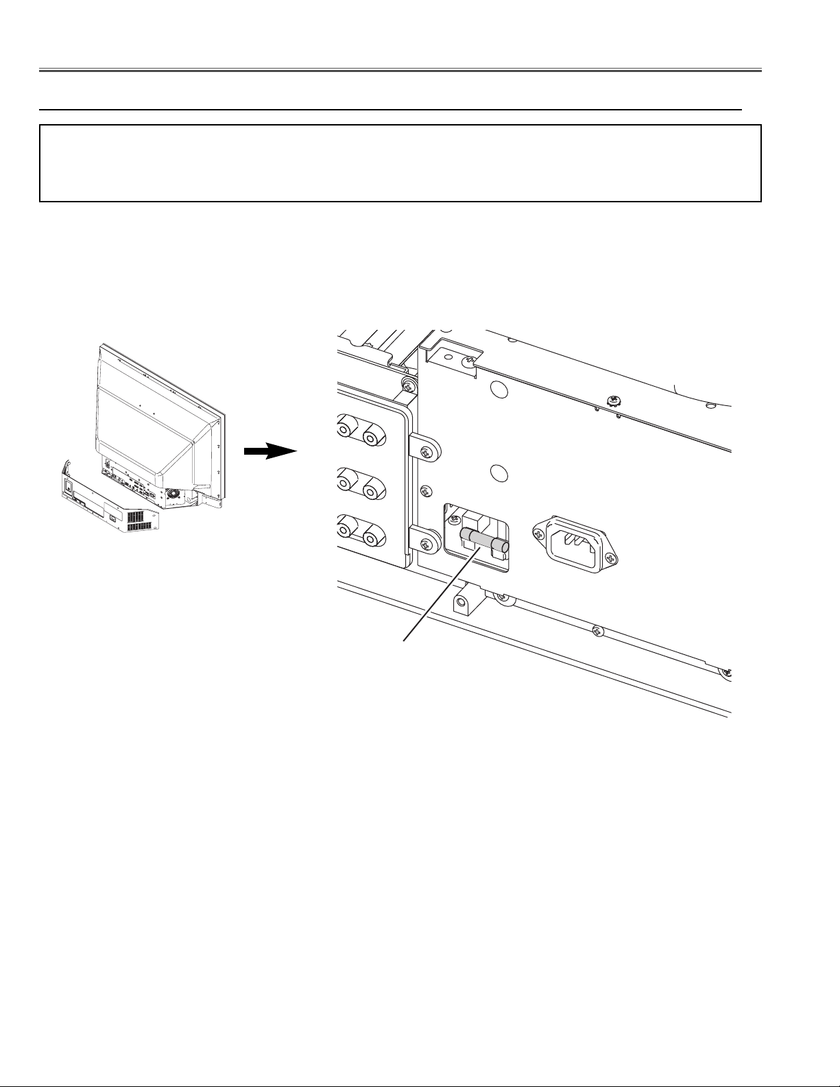
Fuse(F601)
Refer to mechanical disassemblies.
Step 1. Mechanical disassembly 1 P15 (Remove the Cabinet bottom cover.)
Note: The basic steps of mechanical disassemblies are described in pages 15 - 53 in detail.
Please refer to this quick reference of chassis disassemblies for your convenience to ignore
unnecessary steps.
● Quick Reference of Chassis Disassemblies
Fuse
(F601)
Page 2
- 149 -
Appendix
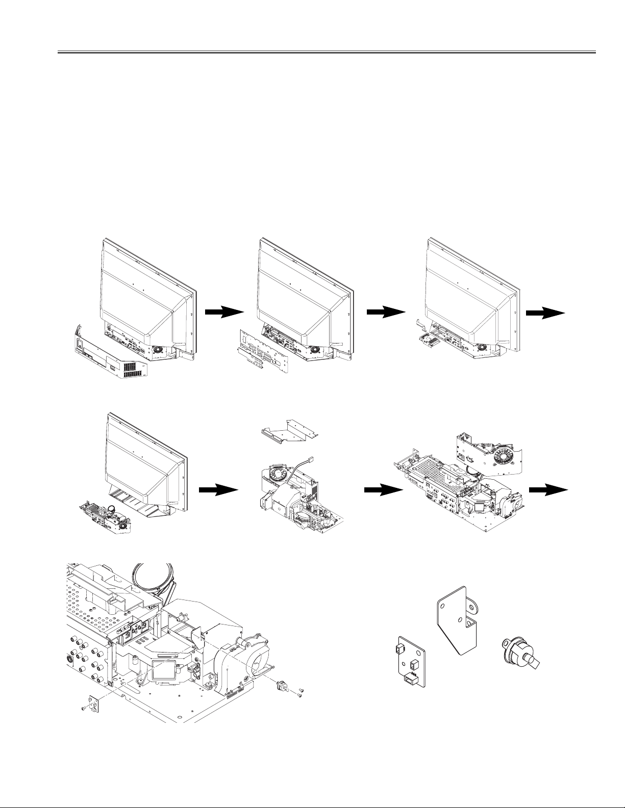
Thermal switch(SW902) and ASSY, PWB, JOINT disassemble (A6801)
Refer to mechanical disassemblies.
Step 1. Mechanical disassembly 1 P15 (Remove the Cabinet bottom cover.)
2. Mechanical disassembly 2 P16 (Remove the Holder bracket back.)
3. Mechanical disassembly 5-1 P20 (Remove the Digital tuner unit.)
4. Mechanical disassembly 6 P22 (Remove the Optical / chassis unit.)
5. Mechanical disassembly 13 P28 (Remove the AC shield top.)
6. Mechanical disassembly 14 P28 (Remove the AC Power unit.)
7. Mechanical disassembly 22 P35 (Remove the SW902 and Joint board.)
Joint Board unit
ASSY, PWB, JOINT(A6801)
Thermal
Switch(SW902)
Page 3
- 150 -
Appendix
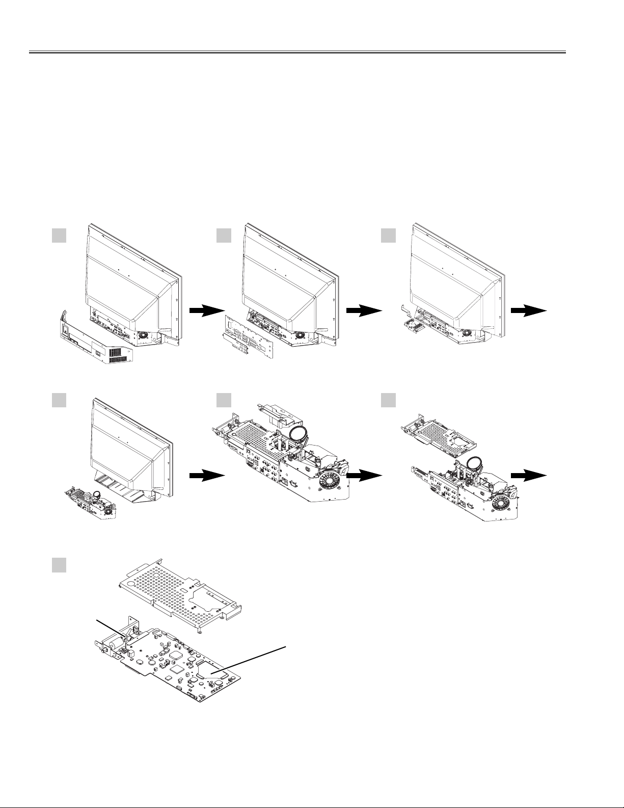
ASSY, PWB, MAIN disassemble (AA301)
Refer to mechanical disassemblies.
Step 1. Mechanical disassembly 1 P15 (Remove the Cabinet bottom cover.)
2. Mechanical disassembly 2 P16 (Remove the Holder bracket back.)
3. Mechanical disassembly 5-1 P20 (Remove the Digital tuner unit.)
4. Mechanical disassembly 6 P22 (Remove the Optical / chassis unit.)
5. Mechanical disassembly 9 P24 (Remove the Duct.)
6. Mechanical disassembly 10-1. P25 (Remove the main board / analog tuner unit.)
7. Mechanical disassembly 10-2 P25 (Remove the main board.)
1 2 3
4
7
6 6
Main board
ASSY,PWB,MAIN (AA301)
TUNER TU/IF
(A101)
Page 4
- 151 -
Appendix
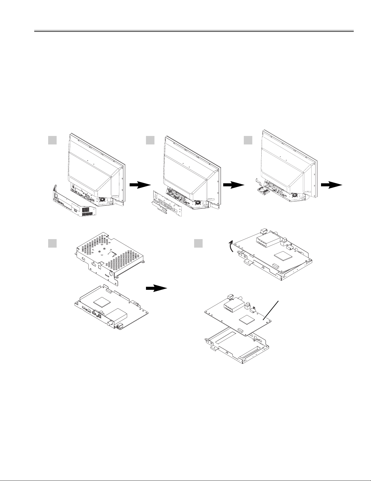
ASSY, PWB, Digital disassemble (AA5501)
Refer to mechanical disassemblies.
Step 1. Mechanical disassembly 1 P15 (Remove the Cabinet bottom cover.)
2.Mechanical disassembly 2 P16 (Remove the Holder bracket back.)
3.Mechanical disassembly 5-1 P20 (Remove the Digital tuner unit.)
4.Mechanical disassembly 5-2 P-21 (Remove the Digital tuner board.)
1 2
4 5
3
Digital tuner board
ASSY,PWB,DIGITAL (AA5501)
Page 5
- 152 -
Appendix
ASSY, UNIT, BALLAST disassemble (A901)
Refer to mechanical disassemblies.
Step 1 Mechanical disassembly 1 P15 (Remove the Cabinet bottom cover.)
2 Mechanical disassembly 2 P16 (Remove the Holder bracket back.)
3 Mechanical disassembly 5-1 P20 (Remove the Digital tuner unit.)
4 Mechanical disassembly 6 P22 (Remove the Optical / chassis unit.)
5 Mechanical disassembly 13 P28 (Remove the AC shield top.)
6 Mechanical disassembly 14 P28 (Remove the AC Power unit.)
7 Mechanical disassembly 15-1 P29 (Disassemble the AC Power unit.)
8 Mechanical disassembly 15-2 P29 (Remove the Unit Ballast.)
1 2 3
4
7 8
5 6
Unit Ballast
ASSY,UNIT,BALLAST (A901)
B
Page 6

- 153 -
Appendix
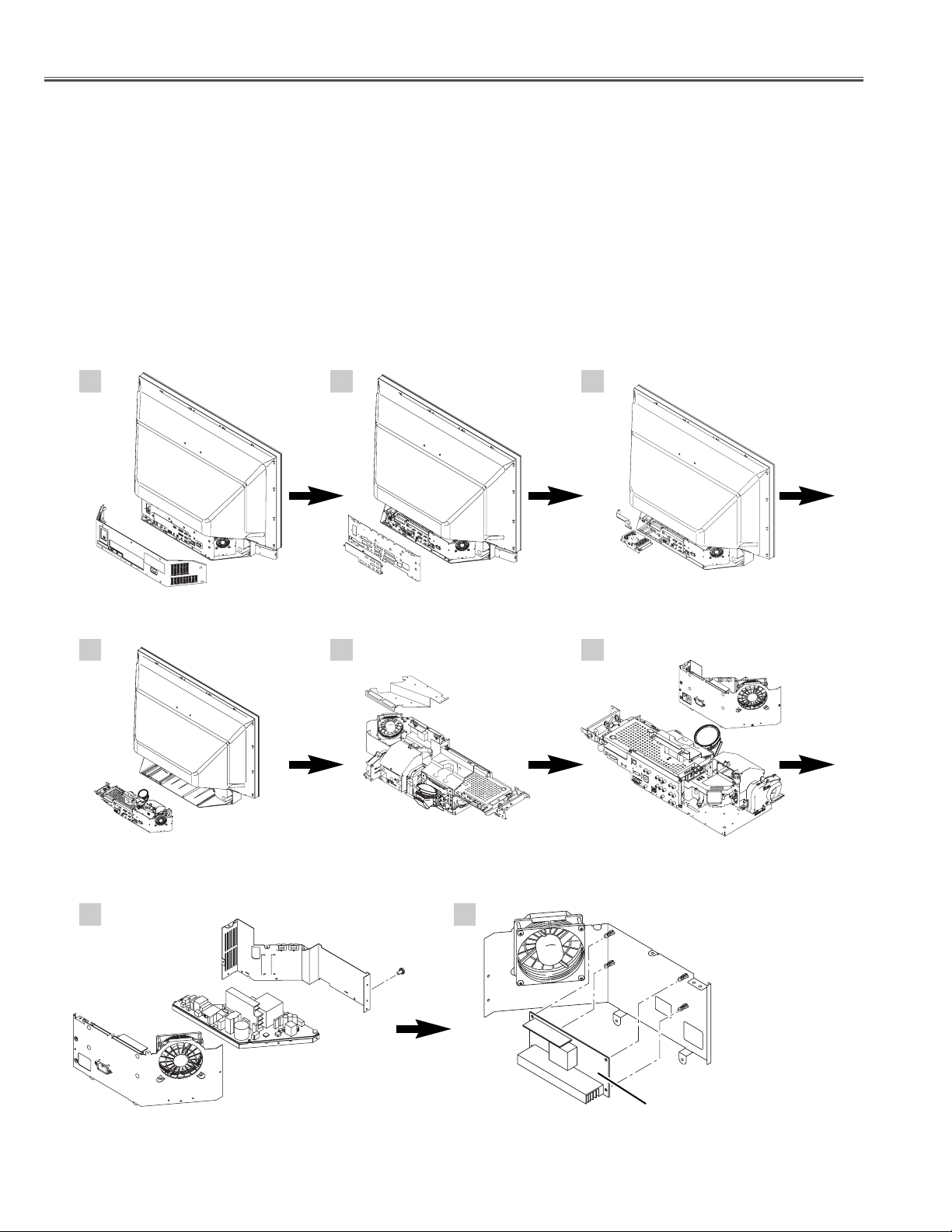
ASSY, PWB, POWER disassemble (AA601)
Refer to mechanical disassemblies.
Step 1 Mechanical disassembly 1 P15 (Remove the Cabinet bottom cover.)
2 Mechanical disassembly 2 P16 (Remove the Holder bracket back.)
3 Mechanical disassembly 5-1 P20 (Remove the Digital tuner unit.)
4 Mechanical disassembly 6 P22 (Remove the Optical / chassis unit.)
5 Mechanical disassembly 13 P28 (Remove the AC shield top.)
6 Mechanical disassembly 14 P28 (Remove the AC Power unit.)
7 Mechanical disassembly 15-1 P29 (Disassemble the AC Power unit.)
8 Mechanical disassembly 15-4 P29 (Remove the Power board.)
7 8
1 2 3
4 5 6
Power board
ASSY,PWB,POWER (AA601)
B
Page 7

- 154 -
Appendix
ASSY, PWB, AV REAR disassemble (A101)
Refer to mechanical disassemblies.
Step 1 Mechanical disassembly 1 P15 (Remove the Cabinet bottom cover.)
2 Mechanical disassembly 2 P16 (Remove the Holder bracket back.)
3 Mechanical disassembly 5-1 P20 (Remove the Digital tuner unit.)
4 Mechanical disassembly 6 P22 (Remove the Optical / chassis unit.)
5 Mechanical disassembly 9 P24 (Remove the Duct.)
6 Mechanical disassembly 10-1 P25 (Remove the main board / analog tuner unit.)
7 Mechanical disassembly 11 P26 (Remove the AV rear board.)
1 2 3
4
7
5 6
AV rear board
ASSY,PWB,AV REAR (A101)
Page 8

- 155 -
Appendix
ASSY, PWB, LED disassemble (A2801)
Refer to mechanical disassemblies.
Step 1. Mechanical disassembly 3 P17 (Remove the Front cover.)
2.Mechanical disassembly 33 P46 (Remove the Front panel unit.)
3.Mechanical disassembly 34 P47 (Remove the LED board.)
1
3
2
LED board
ASSY,PWB,LED (A2801)
Page 9

- 156 -
Appendix
ASSY, PWB, KEY disassemble (A8801)
Refer to mechanical disassemblies.
Step 1. Mechanical disassembly 1 P15 (Remove the Cabinet bottom cover.)
2. Mechanical disassembly 3 P17 (Remove the Front cover.)
3. Mechanical disassembly 4-1 P18 (Remove the side Key board unit.)
4. Mechanical disassembly 4-4 P19 (Disassemble the Cabinet bottom cover.)
5. Mechanical disassembly 4-5 P20 (Remove the Key board.)
1 2
4
5
3
Key board
ASSY,PWB,KEY (A8801)
Page 10

- 157 -
Appendix
ASSY, PWB, COVER SW disassemble (A1801)
Refer to mechanical disassemblies.
Step 1 Mechanical disassembly 1 P15 (Remove the Cabinet bottom cover.)
2. Mechanical disassembly 2 P16 (Remove the Holder bracket back.)
3 Mechanical disassembly 5-1 P20 (Remove the Digital tuner unit.)
4. Mechanical disassembly 6 P22 (Remove the Optical / chassis unit.)
5 Mechanical disassembly 8 P24
1 2
4 5
3
Cover switch board
ASSY,PWB,COVER SW (A1801)
Page 11

- 158 -
MEMO
Page 12

- 159 -
MEMO
Page 13

(PLV-55/65WHD1) OCT. 2006 DC 130 Printed in Japan
SANYO Electric Co., Ltd.
Page 14

documentation manual, user maintenance, brochure, user reference, pdf manual
This file has been downloaded from:
User Manual and User Guide for many equipments like mobile phones, photo cameras, monther board, monitors, software, tv, dvd, and othes..
Manual users, user manuals, user guide manual, owners manual, instruction manual, manual owner, manual owner's, manual guide,
manual operation, operating manual, user's manual, operating instructions, manual operators, manual operator, manual product,
 Loading...