

Sanyo PLC-XW20,PLC-SW20 Service Manual
Multimedia Projector
SERVICE MANUAL
REFERENCE NO. SM5110302-00
CONTENTS
Pages
TECHNICAL SPECIFICATIONS --------------------------------------------------------- 2 - 3
SAFETY INSTRUCTIONS --------------------------------------------------------------------- 4
LAMP REPLACEMENT------------------------------------------------------------------------- 5
PROTECTIONS----------------------------------------------------------------------------------- 6
MECHANICAL DISASSEMBLIES------------------------------------------------------ 7 - 11
ADJUSTMENT ---------------------------------------------------------------------------- 12 - 15
PIN DESCRIPTION OF DIODE, TRANSISTOR AND IC----------------------------- 16
ELECTRICAL PARTS LIST ------------------------------------------------------------ 17 - 53
MECHANICAL PARTS LIST & ACCESSORIES --------------------------------- 54 - 55
SCHEMATIC DIAGRAMS------------------------------------------------------------ A1 - A12
PRINTED WIRING BOARD DIAGRAMS --------------------------------------- A13 - A14
FILE NO.
PRODUCT CODE
1 122 103 00 PLC-XW20 (MW6A)
1 122 104 00 PLC-XW20 (PW6A)
1 122 104 02 PLC-XW20 (PW6C)
1 122 112 00 PLC-SW20 (MZ6A)
1 122 113 00 PLC-SW20 (PZ6A)
1 122 113 02 PLC-SW20 (PZ6C)
ORIGINAL VERSION
Chassis No. MW6-XW2000
(PLC-XW20)
MZ6-SW2000
(PLC-SW20)
Model No. PLC-XW20
PLC-SW20
(U.S.A., Canada, Europe
Asia, Africa U.K.)
NOTE: Match the Chassis No. on the
unit’s back cover with the Chassis
No. in the Service Manual.
If the Original Version Service
Manual Chassis No. does not
match the unit’s, additional
Service Literature is required. You
must refer to “Notices” to the
Original Service Manual prior to
servicing the unit.

-2-
■ Technical Specifications
■ PLC-XW20
0.7" TFT Active Matrix type, 3 panels
Multi-media Projector
6.2lbs (2.8 kg)
10.12" x 2.98" x 9.02" (257mm x 75.8mm x 229mm)
(not including Adjustble Feet and Lens)
1024 x 768 dots
2,359,296 (1024 x 768 x 3 panels)
PAL, SECAM, NTSC, NTSC4.43, PAL-M and PAL-N
H-sync. 15 ~ 100 KHz, V-sync. 50 ~ 100 Hz
Adjustable from 34” to 200”
550 TV lines
1 speaker, ø1.1" (28mm)
41 ˚F ~ 95 ˚F (5 ˚C ~ 35 ˚C)
14 ˚F ~ 140 ˚F (-10 ˚C ~ 60 ˚C)
Owner’s Manual
AC Power Cord
Wireless Remote Control Transmitter and Battery
VGA Cable
Carrying Bag
Lens Cover
Projector Type
Net Weight
Dimensions
(W x H x D)
Panel Resolution
Number of Pixels
Color System
Scanning Frequency
Projection Image size
(Diagonal)
Horizontal Resolution
Built-in Speakers
Operating Temperature
Storage Temperature
Accessories
LCD Panel System
● The specifications are subject to change without notice.
F 1.6 ~ 1.78 lens with f 28.7 mm ~ 34.5 mm with manual zoom and focus
5.3’ ~ 26.6’ (1.6 m ~ 8.1 m)
150 W
RCA Type x 3 (Video/Y, Pb/Cb, Pr/Cr) and Mini DIN 4 pin x 1 (S-Video)
Projection Lens
Throw Distance
Projection Lamp
Video Input Jacks
Mini Jack (stereo) x 1
Audio Input Jacks
(VGA) HDB 15 Terminal x 1
Mini Jack (stereo) x 1
Mini DIN 8 pin x 1
Mini Jack (stereo) x 1
1.0 W RMS
Computer Input Terminals
Computer Audio Input Jack
Control Port Connector
Audio Output Jacks
Internal Audio Amp
0˚ to 10.6˚
Feet Adjustment
Power Source : Lithium Type (CR2025 / 3.0V)
Operating Range : 16.4’ (5m) / ±30˚
Dimensions : 2.1” x 0.28” x 5.3” (54mm x 7mm x 135mm)
Net Weight : 1.27oz (36 g) (including battery)
Remote Control Transmitter
480i, 480p, 575i, 575p, 720p, 1035i, and 1080i
High Definition TV Signal
USB Series B receptacle x 1
USB Connector
AC 100 ~ 120 V (2.8 A Max. Ampere), 50 / 60 Hz
(The U.S.A and Canada)
AC 200 ~ 240 V (1.4 A Max. Ampere), 50 / 60 Hz
(Continental Europe and The U.K.)
Voltage and
Power Consumption
-3-
■ Technical Specifications
■ PLC-SW20
0.7" TFT Active Matrix type, 3 panels
Multi-media Projector
6.2lbs (2.8 kg)
10.12" x 2.98" x 9.02" (257mm x 75.8mm x 229mm)
(not including Adjustable Feet and Lens)
800 x 600 dots
1,440,000 (800 x600 x 3 panels)
PAL, SECAM, NTSC, NTSC4.43, PAL-M and PAL-N
H-sync. 15 ~ 80 KHz, V-sync. 50 ~ 100 Hz
Adjustable from 34” to 200”
500 TV lines (S-Video)
1 speaker, ø1.1" (28mm)
41 ˚F ~ 95 ˚F (5 ˚C ~ 35 ˚C)
14 ˚F ~ 140 ˚F (-10 ˚C ~ 60 ˚C)
Owner’s Manual
AC Power Cord
Wireless Remote Control Transmitter and Battery
VGA Cable
Carrying Bag
Lens Cover
Projector Type
Net Weight
Dimensions
(W x H x D)
Panel Resolution
Number of Pixels
Color System
Scanning Frequency
Projection Image size
(Diagonal)
Horizontal Resolution
Built-in Speaker
Operating Temperature
Storage Temperature
Accessories
LCD Panel System
● The specifications are subject to change without notice.
F 1.6 ~ 1.78 lens with f 28.7 mm ~ 34.5 mm with manual zoom and focus
5.3’ ~ 26.6’ (1.6 m ~ 8.1 m)
150 W
RCA Type x 3 (Video/Y, Pb/Cb, Pr/Cr) and Mini DIN 4 pin x 1 (S-Video)
Projection Lens
Throw Distance
Projection Lamp
Video Input Jacks
Mini Jack (stereo) x 1
Audio Input Jacks
(VGA) HDB 15 Terminal x 1
Mini Jack (stereo) x 1
Mini DIN 8 pin x 1
Mini Jack (stereo) x 1
1.0 W RMS
Computer Input Terminals
Computer Audio Input Jack
Control Port Connector
Audio Output Jacks
Internal Audio Amp
0˚ to 10.6˚
Feet Adjustment
Power Source : Lithium Type (CR2025 / 3.0V)
Operating Range : 16.4’ (5m) / ±30˚
Dimensions : 2.1” x 0.28” x 5.3” (54mm x 7mm x 135mm)
Net Weight : 1.27oz (36 g) (including battery)
Remote Control Transmitter
480i, 480p, 575i, 575p, 720p, 1035i, and 1080i
High Definition TV Signal
USB Series B receptacle x 1
USB Connector
AC 100 ~ 120 V (2.8 A Max. Ampere), 50 / 60 Hz
(The U.S.A and Canada)
AC 200 ~ 240 V (1.4 A Max. Ampere), 50 / 60 Hz
(Continental Europe and The U.K.)
Voltage and
Power Consumption
-4-
■ Safety Instructions
WARNING:
The chassis of this projector is isolated (COLD) from AC line by using the converter transformer. Primary side of
the converter and lamp power supply unit circuit is connected to the AC line and it is hot, which hot circuit is iden-
tified with the line ( ) in the schematic diagram. For continued product safety and protection of personnel
injury, servicing should be made with qualified personnel.
The following precautions must be observed.
1: An isolation transformer should be connected in the power line between the projector and the AC line before any
service is performed on the projector.
2: Comply with all caution and safety-related notes provided on the cabinet back, cabinet bottom, inside the cabi-
net or on the chassis.
3: When replacing a chassis in the cabinet, always be certain that all the protective devices are installed proper-
ly, such as, control knobs, adjustment covers or shields, barriers, etc.
DO NOT OPERATE THIS PROJECTOR WITHOUT THE PROTECTIVE SHIELD IN POSITION AND PROPERLY SECURED.
4: Before replacing the cabinet cover, thoroughly inspect the inside of the cabinet to see that no stray parts or
tools have been left inside.
Before returning any projector to the customer, the service personnel must be sure it is completely safe to operate without danger of electric shock.
■ SAFETY PRECAUTIONS
■ PRODUCT SAFETY NOTICE
Product safety should be considered when a component replacement is made in any area of the projector.
Components indicated by mark in the parts list and the schematic diagram designate components in which
safety can be of special significance. It is, therefore, particularly recommended that the replacement of the parts
must be made by exactly the same parts.
Eye damage may result from directly viewing the light produced by the Lamp used in this equipment. Always turn
off Lamp before opening cover. The Ultraviolet radiation eye protection is required during this servicing.
Never turn the power on without the lamp to avoid electric-shock or damage of the devices since the stabilizer
generates high voltages(20~25kV) at its starts.
Since the lamp is very high temperature during units operation. Replacement of the lamp should be done at least
45 minutes after the power has been turned off, to allow the lamp cool-off.
■ SERVICE PERSONNEL WARNING
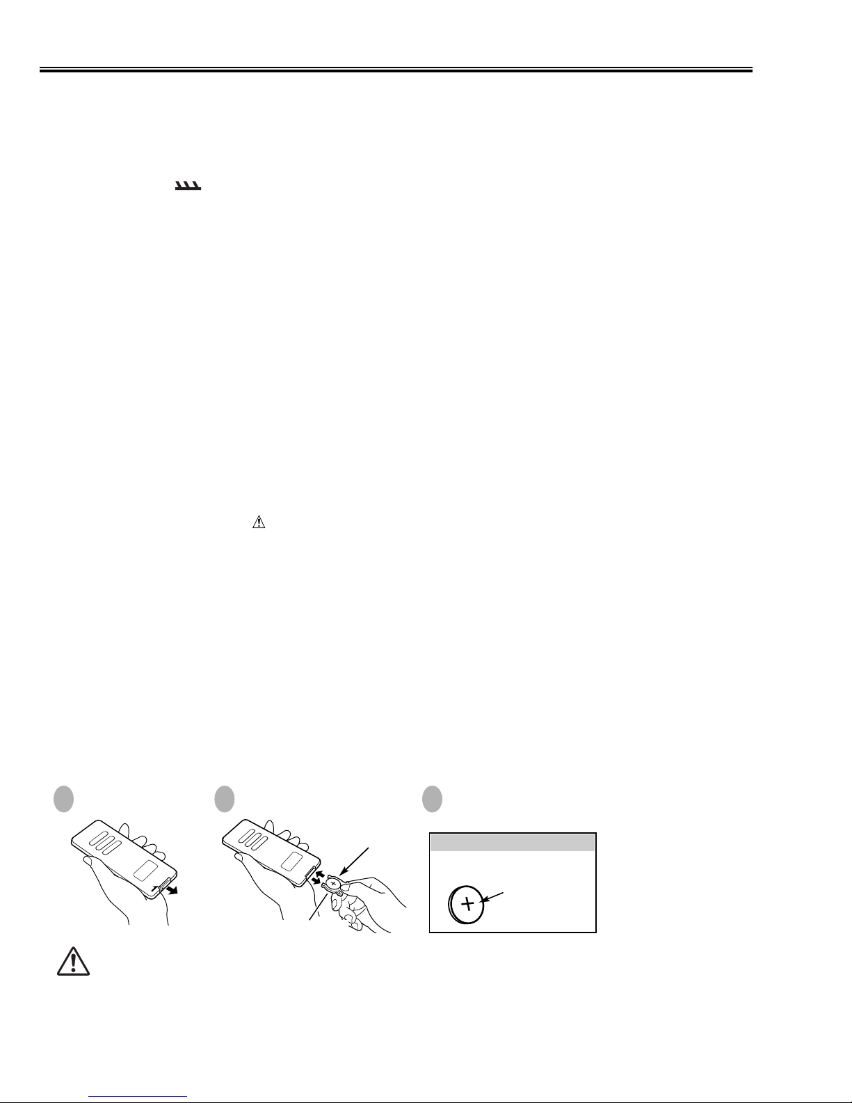
■ REMOTE CONTROL BATTERY INSTALLATION
Pull out Battery Holder.
1 2 3
To insure safe operation, please observe the following precautions :
● Use only specified battery. Improper battery may cause malfunction of Remote Control or a battery.
● Do not expose a battery to moisture or heat. Do not charge a battery.
● If a battery have leaked on Remote Cotrol Unit, carefully wipe the case clean and load a new battery.
● Be sure to install battery with correct polarity.
● Dispose used battery following local regulation.
● Danger of explosion if battery is incorrectly replaced. Replace only with the same or equivalent type
recommended by the manufacturer.
Replace with new battery. Install
with battery (+),(–) marks properly.
Put Battery + mark
as shown direction.
BATTERY HOLDER
Install battery and
Battery Holder into
Remote Control Unit.
BATTERY
LITHIUM BATTERY
CR2025 (3.0V)
(+) mark indicates
its (+) polarity.
-5-
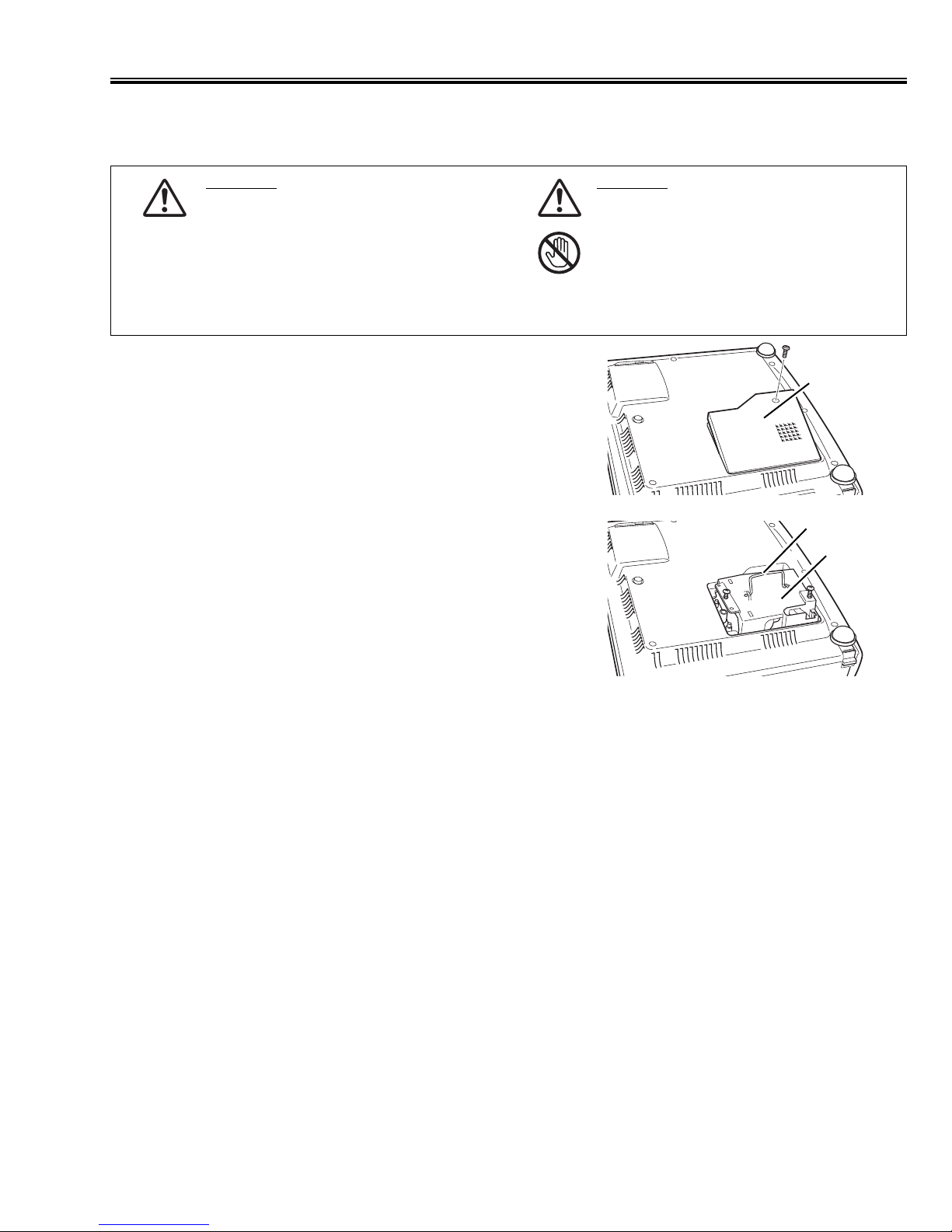
■ Lamp Replacemant
When the life of Projection Lamp of this projector draws to an end, LAMP REPLACEMENT indicator lights yellow.
When a projected image becomes dark or the color of an image becomes unnatural, replacement of Projection
Lamp is required.
CAUTION
Do not drop a lamp assembly or touch a
glass bulb! The glass can shatter and
may cause injury.
CAUTION
For continued safety, replace with a lamp
assembly of the same type.
Allow a projector to cool for at least 45
minutes before you open Lamp Cover.
The inside of a projector can become
very hot.
LAMP
ASSEMBLY
HANDLE
LAMP COVER
Follow these steps to replace the lamp assembly.
1. Turn off the projector and disconnect AC plug. Allow the projector
to cool for at least 45 minutes.
2. Remove a screw with a screwdriver to remove Lamp Cover.
3. Remove 2 screws with a screwdriver and pull out Lamp Assembly
by grasping Handle.
4. Replace Lamp Assembly with a new one and tighten 2 screws
back. Make sure that Lamp Assembly is set properly. Replace
Lamp Cover and tighten a screw.
5. Connect AC Power Cord to the projector and turn it on.
6. Reset Lamp Replace Counter (refer to the section “Lamp Replace
Counter” below).
Do not reset Lamp Replace Counter when Projection Lamp is
not replaced.
■
LAMP REPLACE COUNTER
Be sure to reset Lamp Replace Counter when Lamp Assembly is replaced. When Lamp Replace Counter is
reset, LAMP REPLACE Indicator stops lighting.
1. Turn projector on, press MENU button and ON-SCREEN MENU will appear. Press POINT LEFT/RIGHT
button(s) to move a red frame pointer to SETTING Menu icon.
2. Press POINT DOWN button to move a red frame pointer to “Lamp counter reset” and then press
SET button.
The message "Lamp replace counter reset?" is displayed. Move the pointer to [Yes] and then press SET button.
3.
Another confirmation dialog box appears and select [Yes] to reset Lamp Replace Counter.
Do not reset Lamp Replace Counter except after Projection Lamp is replaced.
-6-
■ Protections
This projector is equipped with the following protections to operate in safety. If the abnormality occurs
inside the projector, it will turn off the projector by operating one of the following protections.
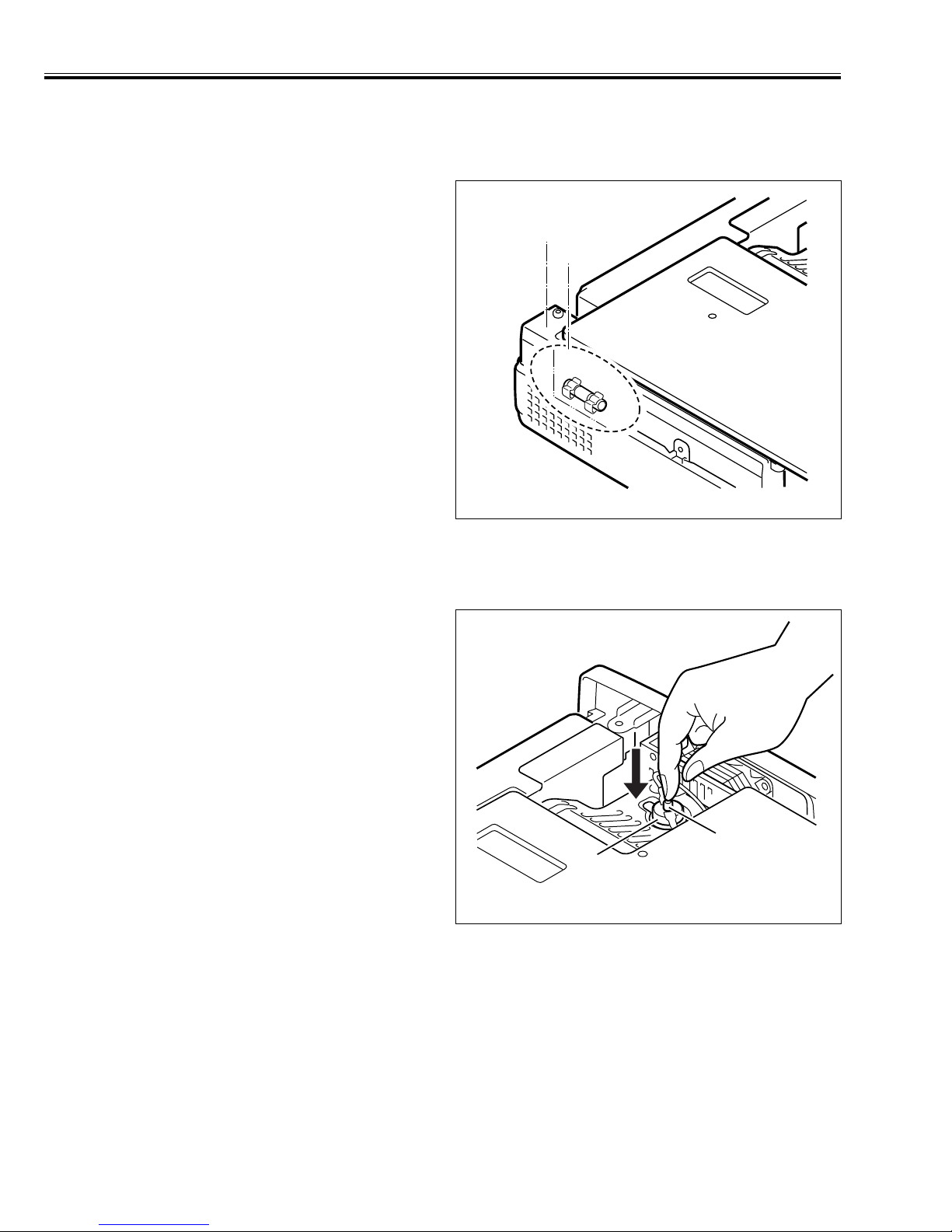
■
FUSE FOR CIRCUIT PROTECTION
The fuse is located on the ass'y-power. When either the
LAMP indicator or the READY indicator is not illuminated,
fuse may be opened. Check the fuse as following steps.
1. Remove the ass'y-power following to “Mechanical
Disassemblies”.
2. Remove the fuse from fuse holder.
3. Check the resistance of fuse by using the tester.
To install the fuse, take reversed step in the above.
It should be used the specified fuse as parts list.
■
OVERHEATING PROTECTION
(The temperature monitor system )
The temperature monitor system is provided to prevents damage of component parts inside the projector from overheat. Two protection systems are provided. Each system operating as follows.
■ Temperature monitor -1 :
When this function operates, warning-temperature-indicator flashes. And cooling fan continues operating until it
becomes a normal temperature. If it continue to flush and
flash does not stopped, disconnect the AC cord and investigate the cause of overheating.
■ Temperature monitor -2 :
(thermal switch SW902)
This function (thermal switch SW902) will not operate,
while the temperature monitor -1 is operating normally. If it
has operated, it needs to be reset manually. Disconnect
the AC cord first and investigate the cause of overheating.
After servicing, reset the thermal switch (SW902) as shown
in a figure.
Holder Power
Ass'y Power
Fuse
Thermal switch(sw902)
Press
Reset button
-7-
■ Mechanical disassemblies
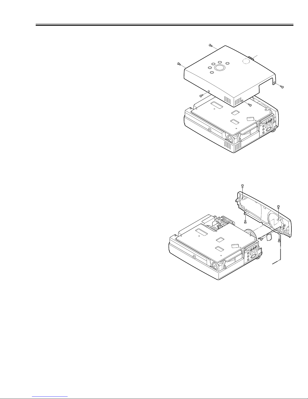
1. CABINET - TOP REMOVAL
1. Remove five screws-A.
2. Grasp the rear both ends of Cabinet-front with both
hands, and slightly pull upward.
3. Release hook, by pressing down "C" portion lightly with
finger.
4. Grasp the rear both ends of Cabinet-front with both
hands, pull up and remove upwards.
Note:
Be careful not to damage Hook. Cabinet-top is being fixed
with cabinet-front by hook.
2.
CABINET - FRONT REMOVAL
1. Remove four screws A and B.
2. Turn the focus-ring of Projection lens fully clockwise.
3. Set zoom-lever of Projection lens to under lens.
4. Slightly pull the upper part of Cabinet-front forward with
both hands. (hook is released and cabinet front is
removed.)
5. Remove a screw and, next, remove Unit R/C.
Note:
Be careful not to damage Hook. There is hook which is fixing Cabinet-front and Cabinet-bottom under Projection
lens.
Screws-A and screws-B are used different kind screws.
Check the kind of screw, and proper screw should be
used.
A
Hook
A
A
C
Cabinet-top
A
Cabinet-front
A
A
Cabinet-front
A
B
R/C
B
Cabinet-bottom
Hook
-8-
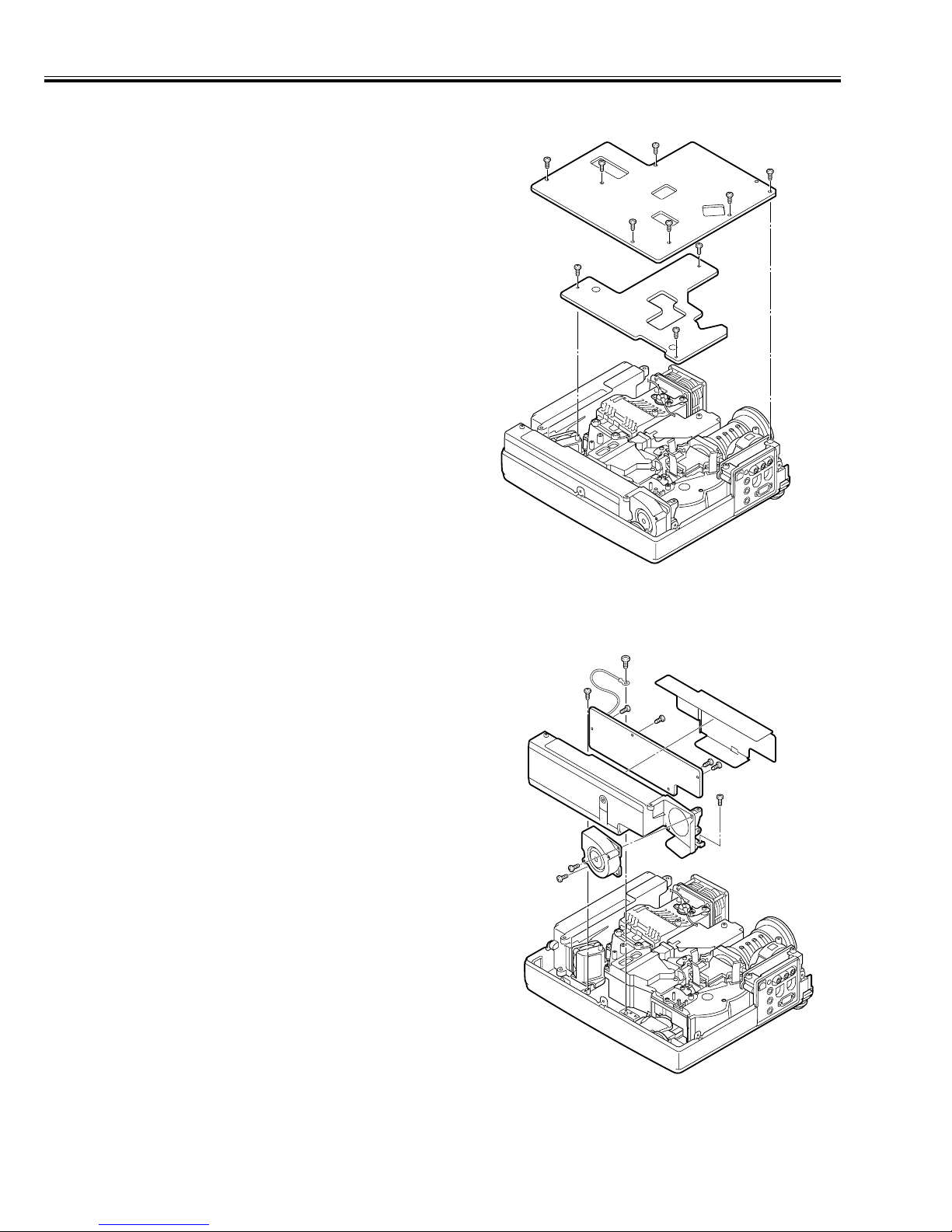
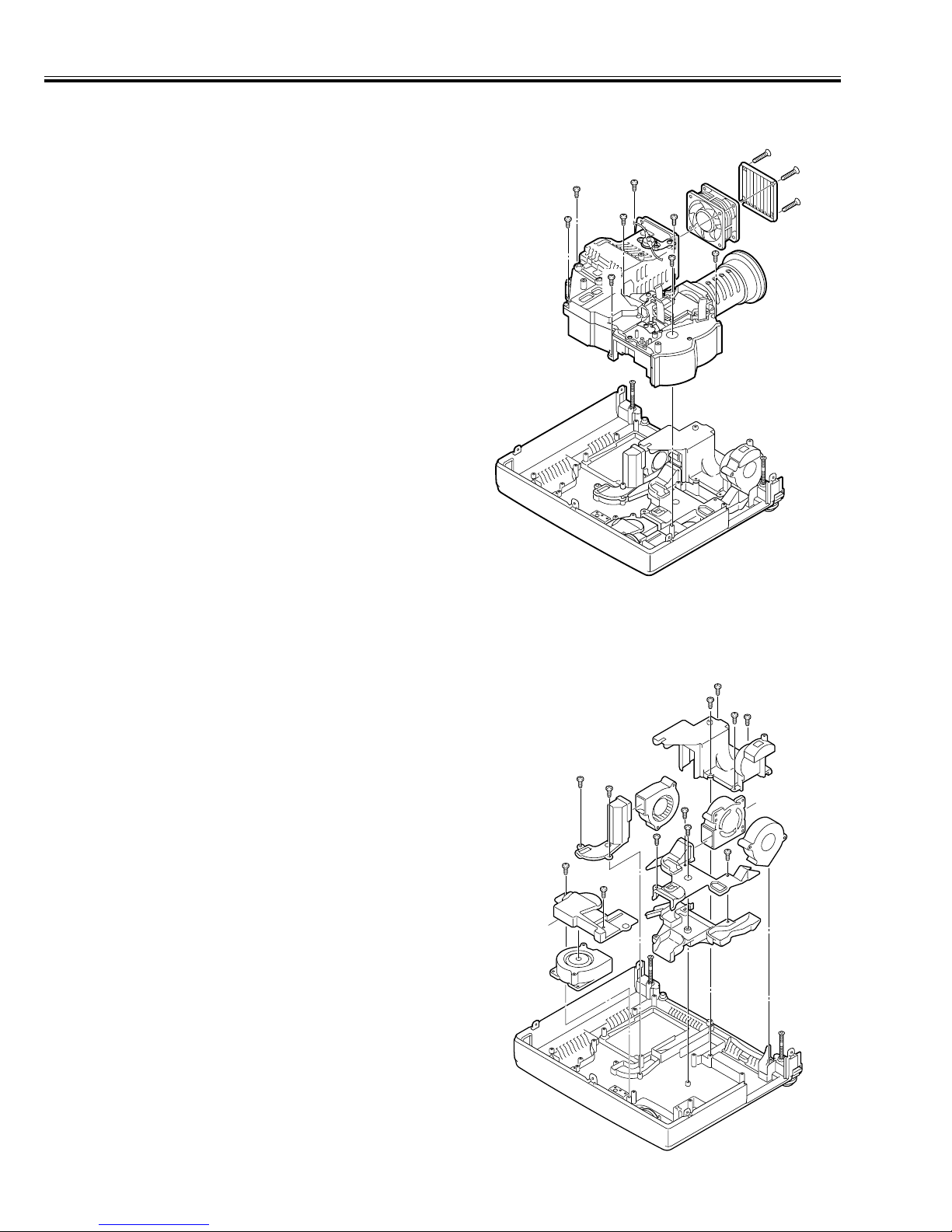
■ Mechanical disassemblies
3. ASS'Y - MAIN AND ASS'Y - SUB REMOVAL
1. Remove seven screws and remove Ass'y Main.
2. Remove three screws and remove Ass'y-Sub.
See figure right.
4. ASS'Y - POWER AND FAN (FN903) REMOVAL
1. Remove seven screws and remove Ass'y Power.
2. Remove two screws and remove Fan (FN903).
See figure right..
M
ain
Sub
FN903
Po
wer
-9-
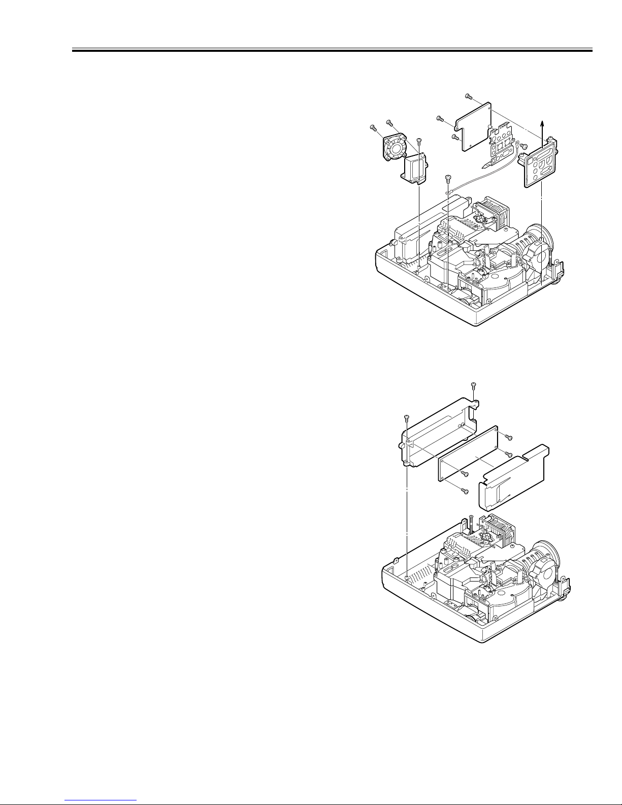
■ Mechanical disassemblies
5. ASS'Y - AV AND FAN (FN907) REMOVAL
1. Remove five screws and remove Ass'y AV.
2. Remove three screws and remove Fan (FN907).
See figure right.
6. ASS'Y - LAMP - BSALLAST REMOVAL
1. Remove six screws and remove Ass'y Lamp-ballast.
AV
FN907
Lam
p ballast
-10-
■ Mechanical disassemblies
7. OPTICAL UNIT, FAN (FN901) AND LOUVER REMOVAL
1. Remove eight screws and remove Optical unit.
2. Remove three screws and remove Fan(FN901) and
louver.
See figure right.
8. AIR DUCTS AND FANS REMOVAL
1. Remove four screws-A and remove Duct-FR and
FN905.
2. Remove two screws-B and remove Duct-PBS and
FN906.
3. Remove three screws-C and remove Duct-TOP and
FN902.
4. Remove two screws-D and remove Duct-TOP-Green
and FN904.
5. Remove screw-E and remove Duct-BTM.
See figure right.
FN901
Louver
Duct-top-Green
A
A
Dukt-FR
B
B
FN906
C
E
C
D
Duct-PBS
D
FN904
A
C
Duct-TOP
Duct-BTM
A
FN902
FN905
-11-
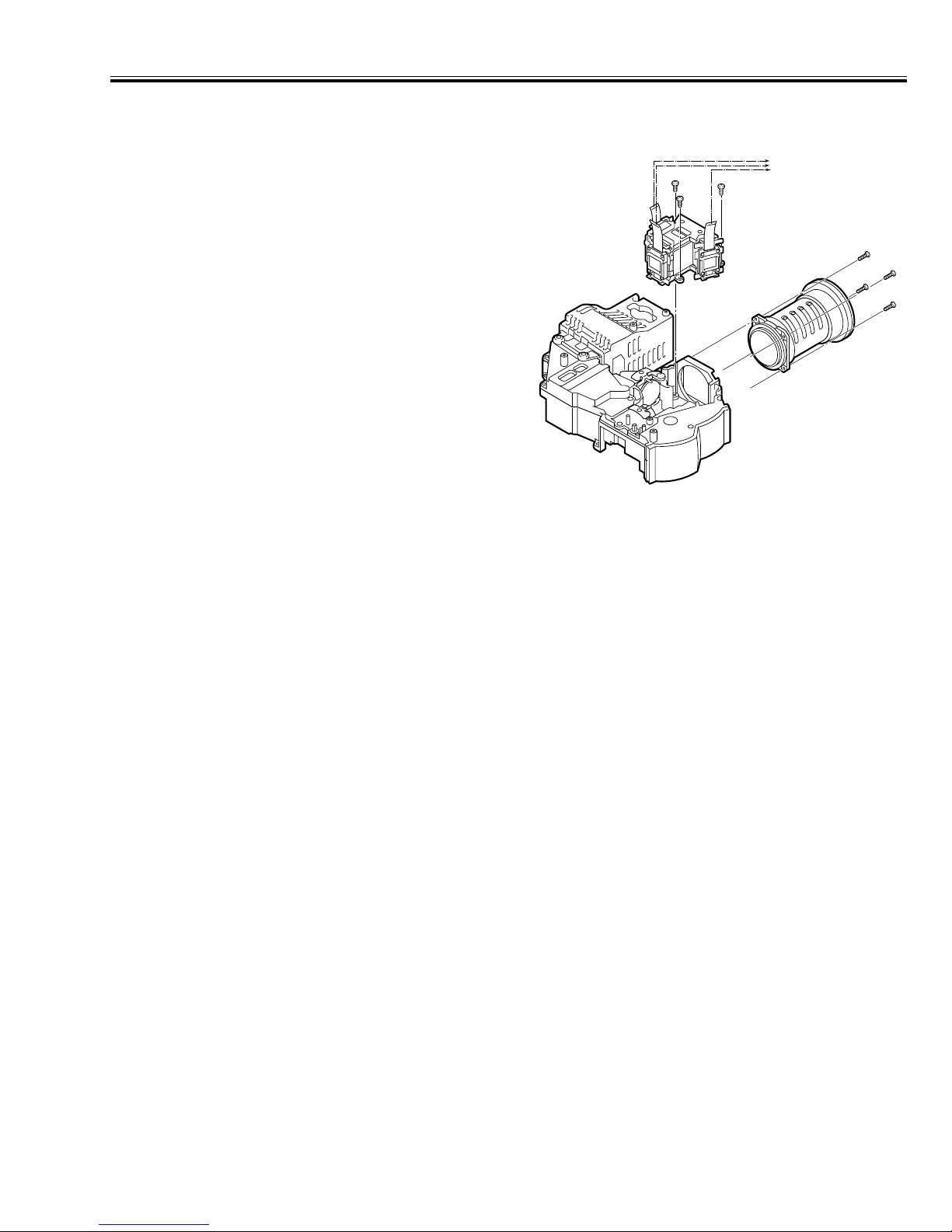
■ Mechanical disassemblies
9. Projection lens and Assembly Panel-Prism removal
1. Remove four screws and remove projection lens.
2. Remove three screws and remove Assembly Panel-
Prism.
See figure right.
Caution :
Don't disassemble Assembly-Panel-Prism other wise
parts may damaged
Never touch the electrode
of flexible cables.
Ass'y P/Prism
Projection lens
-12-
■ Adjustment
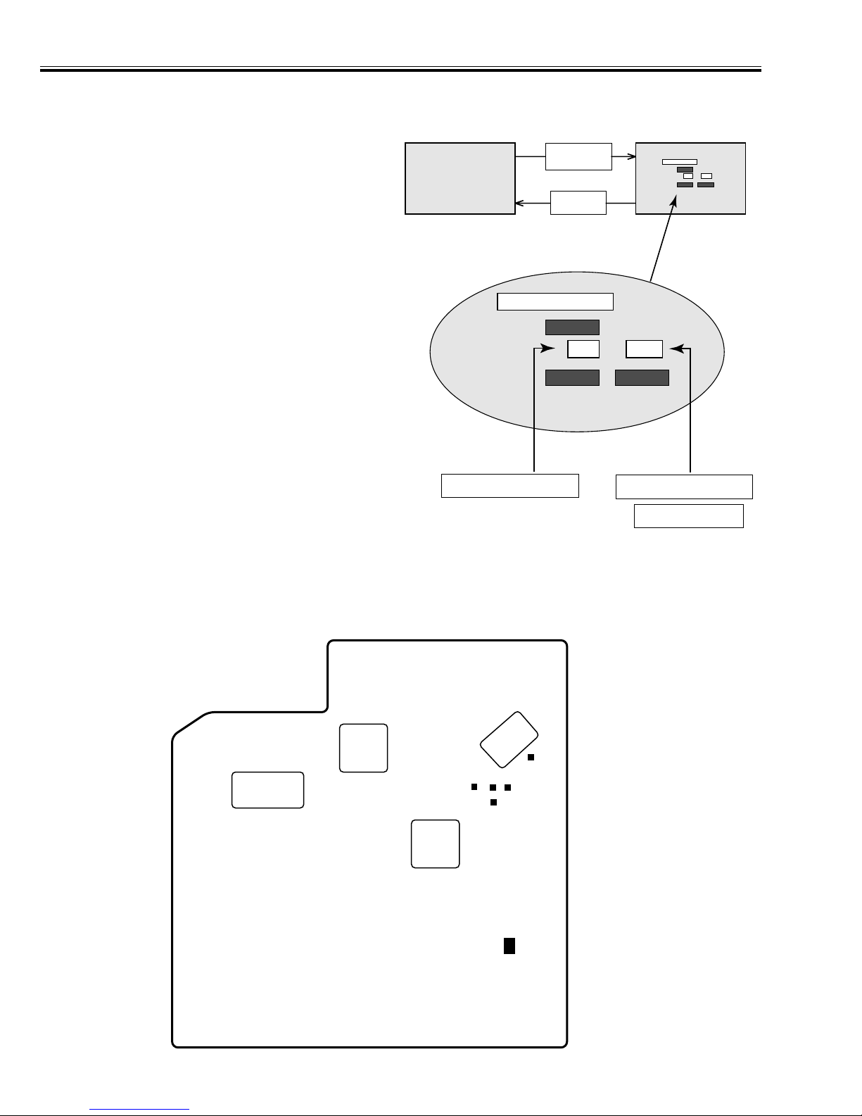
■ SERVICE ADJUSTMENT MENU OPERATION
■ To enter service mode
To enter service mode press the "MENU" and "IMAGE"
buttons on the projector simultaneously and hold for 2
seconds. As shown in a figure, a service mode display
appears on a screen.
■ Adjustment
Adjust service data using the following control buttons.
1. "POINT UP" ------- An item number increases.
2. "POINT DOWN" -- An item number decreases.
3. "POINT RIGHT" -- An adjustment value increases.
"VOLUME+"
4. "POINT LEFT" ---- An adjustment value decreases.
"VOLUME - "
■ To exit service mode
Press the "POWER on/off" button only once on the projec-
tor or remote control unit to quit the service mode.
■ LOCATION OF TEST POINT AND VR
Normal Mode Service Mode
"MENU"
"IMAGE"
"POWER
ON/OFF"
Service Mode
Computer
13710
Service Mode
Computer
13710
"Point Up / Down"
Adjustment item
"Point Left / Right"
"Volume + / -"
TEST POINTS LOCATION
TP-NRS1
TP-R1
TP-B1
Adjustment deta value
TP-66A
TP-G1
ASSY PWB MAIN
VR5601
-13-
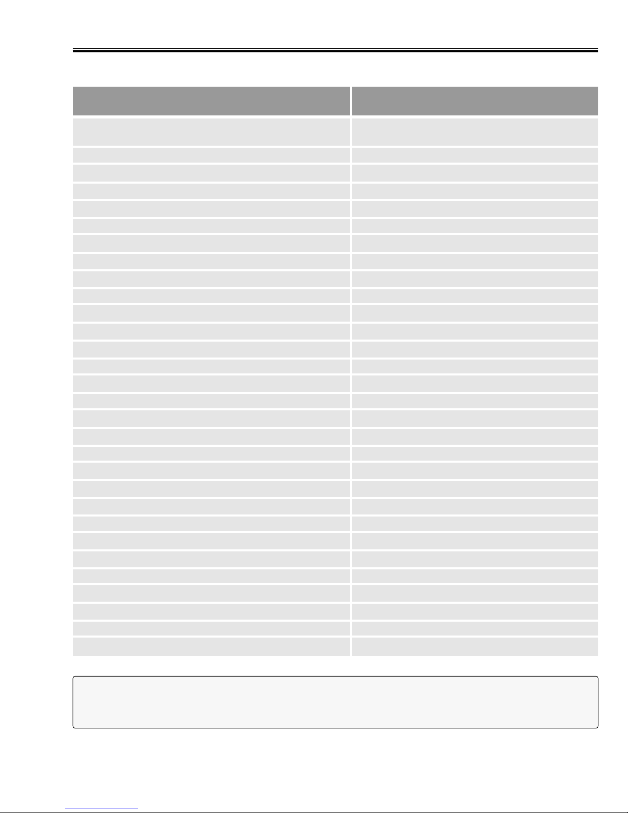
■ Adjustment
Not designated PC AV Component
1 3. Signal center DC adjustment-Red ●
2 3. Signal center DC adjustment-Green ●
3 3. Signal center DC adjustment-Blue ●
7 4. Red contrast adjustment ●● ●
8 4. Green contrast adjustment. ●● ●
9 4. Blue contrast adjustment ●● ●
10 5. Signal amplitude adjustment-Red ●
11 5. Signal amplitude adjustment-Green ●
12 5. Signal amplitude adjustment-Blue ●
16 8. Contrast linearity adjustment ●●
17 7. White balance adjustment-Red ●●
18 7. White balance adjustment-Blue ●●
19 6. Flicker reduction -Red ●
20 6. Flicker reduction -Green ●
21 6. Flicker reduction -Blue ●
22 2. NRS adjustment ●
23 2. NRS adjustment ●
50 1. Fan driving voltage adjustment ●
67 1. Fan driving voltage adjustment ●
Caution :
Other adjustment items are not related to service and a maintenance. Don't press the VOLUME (+) and (-) but-
tons at the time of those adjustment items. Otherwise it may cause loss of product safety.
Item-no.
Adjustment Item
Adjustment Mode
■ SERVICE MODE ADJUSTMENT MENU
-14-
■ Adjustment
■ ELECTRICAL ADJUSTMENTS
1. Fan driving voltage adjustment
Equipment Digital voltmeter.
Test point TP66A
Enter the Service mode.
1. Set the item no. to [50] by pressing the Point up or down
button.
Set the data value to [1] by pressing the Volume + or -
button.
2. Set the item no. to [67]. Set the data value to [1].
3. Adjust the voltages of TP66A to 8.4 ± 0.1 V-DC by the
VR5601.
4. Set the item no. to [50]. Set the data value to [0].
5. Set the item no. to [67]. Set the data value to [1].
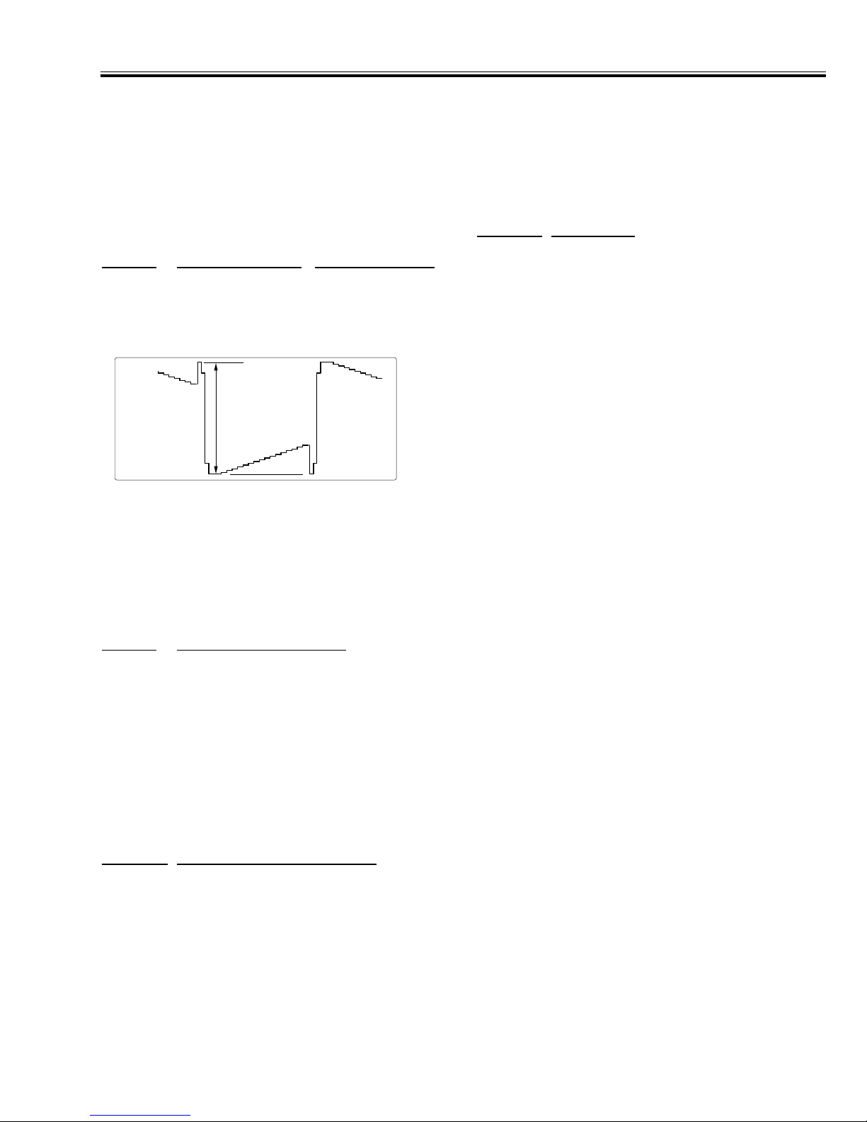
2. NRS adjustments
Equipment Oscilloscope
Test Point TP-NRS1
Input mode Computer
Input Signal 16 step gray scale signal
Enter the Service mode.
Adjust values of below items by the Volume + or - buttons.
Item no.
Adjustment part Adjustment value
22 DC level-A in a figure 2.1 ± 0.1 V-DC.
( for PLC-XW20 )
3.0 ± 0.1 V-DC.
( for PLC-SW20 )
23 DC level-B in a figure 12.0 ± 0.5 V-DC.
3. Signal center DC adjustments
Equipment Digital voltmeter.
Input mode Computer
Input Signal 16 step gray scale signal
Enter the Service mode.
Adjust each values of below test point to be minimum
amplitude by the Volume + or - buttons.
Item no. Test Point Adjustment value
1 TP-R1 7.3 ± 0.05 V-DC.
2 TP-G1 7.3 ± 0.05 V-DC.
3 TP-B1 7.3 ± 0.05 V-DC.
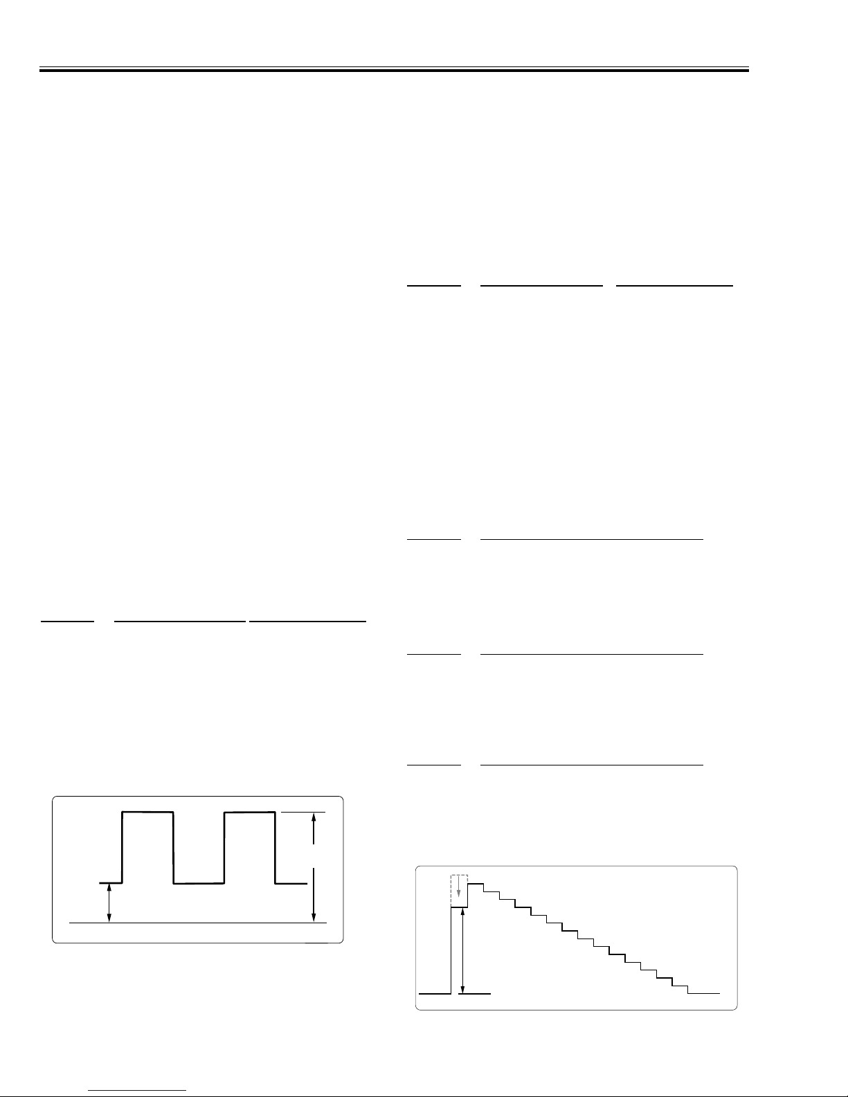
4. Contrast adjustments
Equipment Oscilloscope
Input Signal 16 step gray scale signal
Enter the Service mode.
Adjust each values of below test points in the figure (Part
A) by the Volume + or - buttons.
1-1 Input mode Computer
Item no. Test Point
7 TP-R1 (Red contrast of PC)
8 TP-G1 (Green contrast of PC)
9 TP-B1 (Blue contrast of PC)
1-2 Input mode AV (NTSC)
Item no.
Test Point
7 TP-R1 (Red contrast of AV)
8 TP-G1 (Green contrast of AV)
9 TP-B1 (Blue contrast of AV)
1-3 Input mode Component (480)
Item no. Test Point
7 TP-R1 (Red contrast of Component)
8 TP-G1 (Green contrast of Component)
9 TP-B1 (Blue contrast of Component)
A
GND
B
A
-15-
■ Adjustment
5. Signal Amplitude adjustments
Equipment Oscilloscope
Input mode Computer
Input Signal 16 step gray scale signal
Enter the Service mode.
Adjust the amplitude of part A to be below value for each
test point by the Volume + or - buttons.
Item no. Test Point Adjustment value
10 TP-R1 10.0 ± 0.1 Vp-p
11 TP-G1 10.0 ± 0.1 Vp-p
12 TP-B1 10.0 ± 0.1 Vp-p
6. Flicker Reduction
Input mode Computer
Input Signal 1dot computer signal
Enter the Service mode.
Adjust to be minimum flicker for each color by the Volume
+ or - buttons.
Item no.
Screen
19 Only red color picture
20 Only green color picture
21 Only blue color picture
7. White Balance Adjustments
Input Signal 16 step gray scale signal
Enter the Service mode.
Adjust each value of below item to be good white balance
by the Volume + or - buttons.
Item no. Imput Mode
17 and 18 Computer
17 and 18 AV (NTSC)
(17:Red, 18:Blue)
Note:
The white balance of Computer and AV pictures should be
same.
8. Contrast Linearity Adjustments
Input Signal 16 step gray scale signal
Enter the Service mode.
If the black or white saturated picture can be seen, adjust
the value of below item to be reduced it by the Volume + or
- buttons.
Item no. Imput Mode
16 Computer
16 AV (NTSC)
A
-16-
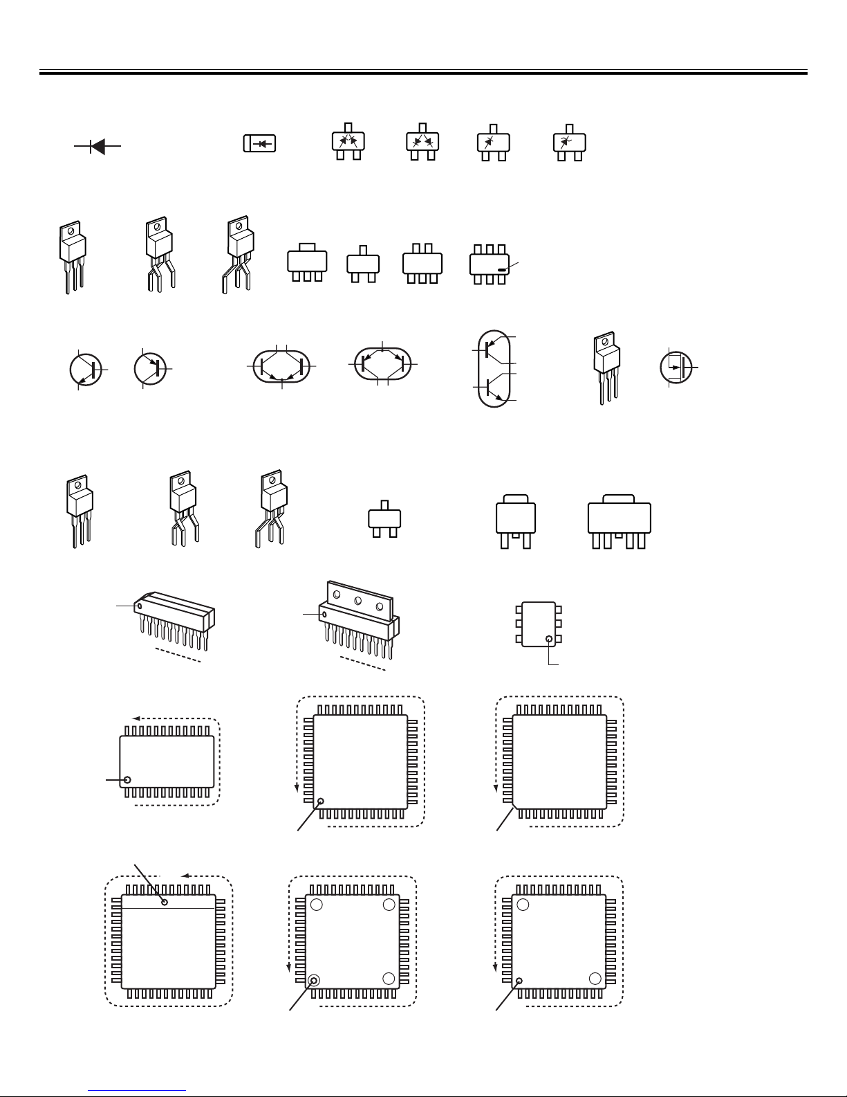
■ Pin Description of Diode, Transistor and IC
● Diode
K
A
● Transistor/FET
E
C
B
C
E
C
B
E
B
C
● IC
K
A
K
A
K
K
K: Cathode
A: Anode
AA
C
E
E
B
C
B
B1
C1
CBE
C2
B2
E
C
BE
B1
C1
E
C2
Vdd
2
KK
C1
C2
B1 B2
E
B2
C2
E2 C1
B1
B2
A
B1
E1
B2
(GND)
Index
E1
C1
C2
E2
2
A
C: Collector
B: Base
E: Emitter
D: Drain
G: Gate
S: Source
S
G
D
S
D
G
3
1
3
2
Index
Index
N
1
Index
1
3
2
Index
Index
1
3
N
GND
(IN)
Index
3
1
(OUT)
4
5
6
21
5
4
3
2
1
Index
N
1
RESET
1
2
N
1
2
1
2
1
3
1
N
N
N
Index
N
1
Index
1
-17-
■ Electrical Parts List
Product safety should be considered when a component replacement is made in any area of a projector.
Components indicated by a mark in this parts list and the circuit diagram show components whose value have
special significance to product safety. It is particularly recommended that only parts specified on the following parts
list be used for components replacement pointed out by the mark.
!
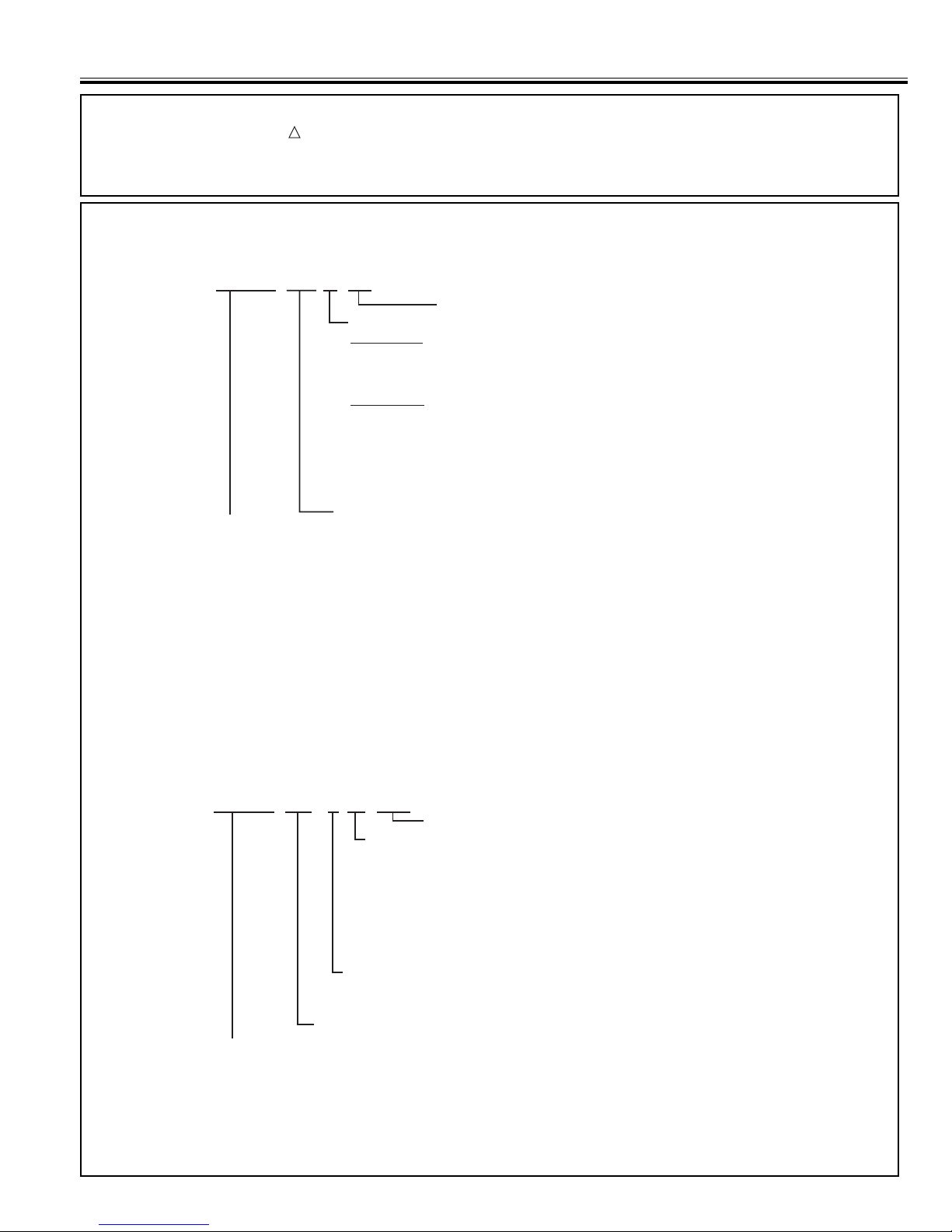
● Read Description in the parts list
Read description in the Capacitor and Resistor as follows:
CAPACITOR
CERAMIC 100P K 50V
Rated Voltage
Tolerance Symbols:
Less than 10pF
A : Not specified B : ±0.1pF C : ±0.25pF
D : ±0.5pF E : +0 -1pF F : ±1PF
G : ±2pF H : +0.1 -0pF L : +0 -0.1pF
R : ±0.25 -0pF S : +0-0.25pF
More than 10pF
A : Not specified B : ±0.1% C : ±0.25%
D : ±0.5% F : ±1% G : ±2%
H : ±3% J : ±5% K : ±10%
L : ±15% M : ±20% N : ±30%
P : +100-0% Q : +30-10% T : +50-10%
U : +75-10% V : +20-10% W : +100-10%
X : +40-20% Y : +150-10% Z : +80-20%
Material:
CERAMIC........... Ceramic
MT-PAPER......... Metallized Paper
POLYESTER...... Polyester
MT-POLYEST.....Metallized Polyester
POLYPRO.......... Polypropylene
MT-POLYPRO....Metallized Polypropylene
COMPO FILM.....Composite film
MT-COMPO........Metallized Composite
STYRENE...........Styrene
TA-SOLID........... Tantalum Oxide Solid Electrolytic
AL-SOLID........... Aluminium Solid Electrolytic
ELECT................ Aluminum Foil Electrolytic
NP-ELECT..........Non-polarised Electrolytic
OS-SOLID.......... Aluminium Solid with Organic Semiconductive Electrolytic
POS-SOLID........ Polymerized Organic Semiconductive
DL-ELECT.......... Double Layered Electrolytic
PPS-FILM...........Polyphenylene Sulfide Film
MT-PPS-FILM.....Metalized Polyphenylene Sulfide Film
MT-PEN-FILM.....Metalized Polyethylenenaphthalate Film
CAPACITOR.......Other
Rated value: P=pico farad, U=micro farad
RESISTOR
CARBON 4.7K J A 1/4W
Rated value, ohms:
Material:
CARBON........... Carbon
MT-FILM............ Metal Film
OXIDE-MT......... Oxide Metal Film
SOLID................ Composition
MT-GLAZE......... Metal Glaze
WIRE WOUND...Wire Wound
CERAMIC RES.. Ceramic
FUSIBLE RES....Fusible
RESISTOR ........Other
K: 1,000, M: 1,000,000
Rated Wattage
Performance Symbols:
A: General B: Non flammable Z: Low noise
Other: Temperature coefficient
T: ±10ppm/°C U: ±25ppm/°C C: ±50ppm/°C
D: ±100ppm/°C E: ±200ppm/°C F: ±250ppm/°C
G: ±350ppm/°C H: ±1000ppm/°C±10% W: ±1200ppm/°C±10%
Y: ±1400ppm/°C±10% J: ±2000ppm/°C±10% K: ±2400ppm/°C±10%
L: ±2700ppm/°C±10% M: ±3000ppm/°C±10% N: ±3300ppm/°C±10%
P: ±3600ppm/°C±10% Q: ±3900ppm/°C±10% R: ±4200ppm/°C±10%
S: ±4300ppm/°C±10% V: ±4500ppm/°C±10% X: ±8000ppm/°C±10%
Tolerance Symbols:
A: ±0.05% B: ±0.1% C: ±0.25% D: ±0.5%
F: ±1% G: ±2% J: ±5% K: ±10%
M: ±20% P: +5-15% Z: 0 ohm
 Loading...