

Sanyo PLC-XU88-WXU30 Owner's Manual
Network Set-up
and Operation
Wired and Wireless Setting
Projector Set-up and Operation
Network Capture
Network Viewer
Moderator Function
Owner’s Manual
EnglishFrançaisEspañolDeutschItaliano
This is the manual for the Network function.
Read this manual thoroughly to operate the Network function.
First, read the owner's manual of the projector to understand the basic operation of the
projector and the safety instructions.
The safety instructions in the owner's manuals should be followed strictly.

2
Compliance
For Canadian Users
This Class B digital apparatus complies with Canadian ICES-003.
Cet apparei numérique de la classe B est conforme à la norme NMB-003 du Canada.
FCC Warning
Changes or modifications not expressly approved by the party responsible for compliance could void
the user’s authority to operate the equipment.
FCC RF Exposure Warning
- This transmitter must be co-located or operated in conjunction with any other antenna or transmitter.
- This equipment complies with FCC radiation exposure limits set forth for uncontrolled equipment and
meets the FCC radio frequency (RF) Exposure Guidelines in Supplement C to OET65. This equipment
must be installed and operated with at least 20cm and more between the radiator and person’s body
(excluding extremities: hands, wrists, feet and ankles).
Federal Communications Commission Notice
This equipment has been tested and found to comply with the limits for a Class B digital device,
pursuant to part 15 of the FCC Rules. These limits are designed to provide reasonable protection
against harmful interference in a residential installation. This equipment generates, uses and can
radiate radio frequency energy and, if not installed and used in accordance with the instructions, may
cause harmful interference to radio communications. However, there is no guarantee that interference
will not occur in a particular installation. If this equipment does cause harmful interference to radio
or television reception, which can be determined by turning the equipment off and on, the user is
encouraged to try to correct the interference by one or more of the following measures:
– Reorient or relocate the receiving antenna.
– Increase the separation between the equipment and receiver.
– Connect the equipment into an outlet on a circuit different from that to which the receiver is
connected.
– Consult the dealer or an experienced radio/TV technician for help.
Model Number : QXXAVC922---P
Trade Name : Sanyo
Responsible party : SANYO FISHER COMPANY
Address : 21605 Plummer Street, Chatsworth, California 91311
Telephone No. : (818)998-7322
This device complies with Part 15 of FCC Rules and RSS-Gen of IC Rules. Operation is subject to the
following two conditions: (1) the device may not cause interference, and (2) the device must accept any
interference, including interference that may cause undesired operation of this device.
CAUTION: Properly shielded a grounded cables and connectors must be used for connection to host
computer and /or peripherals in order to meet FCC emission limits.
VGA cable with ferrite core must be used for RF interference suppression.
3
English
The CE Mark is a Directive conformity mark of the
European Community (EC).
The Alert Mark is a Directive conformity mark of the
European Community.
English
Hereby, SANYO Electric Co., Ltd., declares that this WLAN Module (QXXAVC922---P) is in compliance
with the essential requirements and other relevant provisions of Directive 1999/5/EC.
Česky
[Czec h]
SANYO Electric Co., Ltd. tímto prohlašuje, že tento WLAN Module (QXXAVC922---P) je ve shodě se
základními požadavky a dalšími příslušnými ustanoveními směrnice 1999/5/ES.
Dansk
[Danish]
Undertegnede SANYO Electric Co., Ltd. erklærer herved, at følgende udstyr WLAN Module
(QXXAVC922---P) overholder de væsentlige krav og øvrige relevante krav i direktiv 1999/5/EF.
Deutsch
[German]
Hiermi t erklä rt SANYO Electr ic Co., Ltd., dass sich das G erät WL AN Module (QXXAVC922-- -P) in
Übereinstimmung mit den grundlegenden Anforderungen und den übrigen einschlägigen
Bestimmungen der Richtlinie 1999/5/EG befindet.
Eesti
[Estonian]
Käesolevaga kinnitab SANYO Electric Co., Ltd. seadme WLAN Module (QXXAVC922---P) vastavust
direktiivi 1999/5/EÜ põhinõuetele ja nimetatud direktiivist tulenevatele teistele asjakohastele
sätetele.
Español
[Spanish]
Por medio de la presente SANYO Electric Co., Ltd. declara que el WLAN Module (QXXAVC922---P)
cumple con los requisitos esenciales y cualesquiera otras disposiciones aplicables o exigibles de la
Directiva 1999/5/CE.
Ελληνική
[Gree k]
ΜΕ ΤΗΝ ΠΑΡΟΥΣΑ SANYO Ele ct ric Co., Ltd . ΔΗΛΩΝΕΙ ΟΤΙ WL AN M odule (QXXAVC922-- -P)
ΣΥΜΜΟΡΦΩΝΕΤΑΙ ΠΡΟΣ ΤΙΣ ΟΥΣΙ ΩΔΕΙΣ ΑΠΑΙΤΗΣΕΙΣ Κ ΑΙ Τ ΙΣ ΛΟ ΙΠΕΣ ΣΧΕΤ ΙΚΕΣ ΔΙΑΤΑΞΕΙΣ ΤΗΣ
ΟΔΗΓΙΑΣ 1999/5/ΕΚ.
Franç ais
[French]
Par la présente SANYO Electric Co., Ltd. déclare que l’appareil WLAN Module (QXXAVC922---P) est
conforme aux exigences essentielles et aux autres dispositions pertinentes de la directive 1999/5/CE.
Italiano
[Italian]
Con la presente SANYO Electric Co., Ltd. dichiara che questo WLAN Module (QXXAVC922---P) è
conforme ai requisiti essenziali ed alle altre disposizioni pertinenti stabilite dalla direttiva 1999/5/CE.
Latviski
[Latvian]
Ar šo SANYO Electric Co., Ltd., deklarē, ka WLAN Module (QXXAVC922---P) atbilst Direktīvas 1999/5/
EK būtiskajām prasībām un citiem ar to saistītajiem noteikumiem.
Lietuvių
[Lithuanian]
Šiuo SANYO Electric Co., Ltd.deklaruoja, kad šis WLAN Module (QXXAVC922---P) atitinka esminius
reikalavimus ir kitas 1999/5/EB Direktyvos nuostatas.
Nederlands
[Dutch]
Hierbij verklaart SANYO Electric Co., Ltd. dat het toestel WLAN Module (QXXAVC922---P) in
overeenstemming is met de essentiële eisen en de andere relevante bepalingen van richtlijn 1999/5/
EG.
Malti
[Maltese]
Hawnhekk, SANYO Electric Co., Ltd., jiddikjara li dan WLAN Module (QXXAVC922---P) jikkonforma
mal-ħtiġijiet essenzjali u ma provvedimenti oħrajn relevanti li hemm fid-Dirrettiva 1999/5/EC.
Magyar
[Hungarian]
Alulírott, SANYO Electric Co., Ltd. nyilatkozom, hogy a WLAN Module (QXXAVC922---P) megfelel a
vonatkozó alapvetõ követelmé nyeknek és az 1999/5/EC irányelv eg yéb elõírásainak.
Polski
[Polish]
Niniejszym SANYO Electric Co., Ltd. oświadcza, że WLAN Module (QXXAVC922---P) jest zgodny z
zasadniczymi wymogami oraz pozostałymi stosownymi postanowieniami Dyrekt ywy 1999/5/EC.
Português
[Portuguese]
SANYO Electric Co., Ltd. declara que este (QXXAVC922---P) está conforme com os requisitos
essenciais e outras disposições da Directiva 1999/5/CE.
Slovensko
[Slovenian]
SANYO Electric Co., Ltd. izjavlja, da je ta (QXXAVC922---P) v skladu z bistvenimi zahtevami in ostalimi
relevantnimi določili direktive 1999/5/ES.
Slovensky
[Slovak]
SANYO Electric Co., Ltd. týmto vyhlasuje, že (QXXAVC922---P) spĺňa základné požiadavky a všetky
príslušné ustanovenia Smernice 1999/5/ES.
Suomi
[Finnish]
SANYO Electric Co., Ltd. vakuuttaa täten että (QXXAVC922---P) tyyppinen laite on direktiivin 1999/5/
EY oleellisten vaatimusten ja sitä koskevien direktiivin muiden ehtojen mukainen.
Svensk a
[Swedish]
Härmed intygar SANYO Electric Co., Ltd. att denna (QXXAVC922---P) står I överensstämmelse med de
väsentliga egenskapskrav och övriga relevanta bestämmelser som framgår av direktiv 1999/5/EG.
Islenska
[Icelandic]
Hér með lýsir SANYO Electric Co., Ltd. y fir því að (QXXAVC922---P) er í samræmi við grunnkröfur og
aðrar kr öfur, sem gerðar eru í ti lskipun 1999/5/EC.
Norsk
[Norwegian]
SANYO Electric Co., Ltd. erklærer herved at utstyret (QXXAVC922---P) er i samsvar med de
grunnleggende krav og øvrige relevante krav i direktiv 1999/5/EF.
4
Safety instructions
Caution about Radio Wave
This unit operates in 2.4 GHz band, the same frequency band used for industrial, scientific, and medical
equipment (such as pacemaker), as well as amateur radio stations.
Please read “Safety Instructions” section and make sure the following cautions.
1. Be sure that there are no other devices in the area that may use the same frequency band as
Projector.
2. If any other devices are causing radio interferences, change the communication frequency channel
or move to other location.
Trademarks and Copyright
Microsoft, Windows, and Internet Explorer are either registered trademarks or trademarks of Microsoft
Corporation in the United States and/or other countries.
Netscape Navigator and Netscape Communicator are registered trademarks or trademarks of Netscape
Communications Corporation in the United States and other countries.
Pentium is a registered trademark of Intel Corp. in the United States.
Each name of corporation or product in this Owner’s Manual is either a registered trademark or a
trademark of its respective corporation.
Notes
- The contents of this manual are subject to change without notice.
- You may not copy the printed materials accompanying with the software.
- We shall not be responsible for any damages caused by reliance on this manual.
Expression/Abbreviation
The OS of the computer and the Web browser described in this manual is Windows XP Professional and
Internet Explorer 6.0. In case of another OS or Web browser, some instruction procedures may differ
from the actual operation depending on your computer environment.
Use of this manual
This manual does not provide the description of basic operation and functions for computer, web
browser, projector and network. For instructions about each piece of equipment or application
software, please refer to the respective booklet.
CAUTION IN USING THE PROJECTOR VIA NETWORKS
L When you find a problem with the projector, remove the power cable immediately and inspect
the unit. Using the projector with failure may cause fire or other accidents.
L If you remotely use the projector via networks, carry out a safety check regularly and take
particular care to its environment. Incorrect installation may cause fire or other accidents.
CAUTION IN USING NETWORK FUNCTION
L SANYO Electric Co., Ltd. assumes no responsibility for the loss or damage of data, or damage of
the computer caused by using this projector. Making back-up copies of valuable data in your
computer is recommended.

5
English
Table of contents
Compliance .........................................................................................................................................................2
Safety instructions............................................................................................................................................4
Table of contents...............................................................................................................................................5
Operating environment and configuration.............................................................................................7
Required operating environment for computers..............................................................................7
Network specifications of the projector................................................................................................8
1. About LAN functions ....................................................9
LAN functions and the features................................................................................................................10
Image projecting system via LAN............................................................................................................ 10
An example of the connection .................................................................................................................11
LAN connection modes...............................................................................................................................12
2. Setup procedures .........................................................15
Installing the software .................................................................................................................................17
3. Names and functions of the operation screen ...........21
Network connection standby display....................................................................................................22
Network Capture 4 window.......................................................................................................................23
4. Wired LAN configurations ...........................................25
Connecting to the LAN line........................................................................................................................26
Network environment settings.................................................................................................................26
Confirming the operation...........................................................................................................................28
Network PIN code..........................................................................................................................................30
Network information....................................................................................................................................30
Wired factory default....................................................................................................................................30
Wired LAN factory default settings.........................................................................................................31
5. Wireless LAN configurations.......................................33
Setting the network environment...........................................................................................................34
Setting procedures........................................................................................................................................34
Configuring security with the projector................................................................................................36
Easy wireless setting.....................................................................................................................................39
Network PIN code..........................................................................................................................................40
Network information....................................................................................................................................40
Wireless factory default...............................................................................................................................40
WIRELESS indicator display........................................................................................................................41
Wireless LAN factory default settings ....................................................................................................42
6. Basic setting and operation.........................................43
Starting up the Browser ..............................................................................................................................44

6
How to use the setting page .....................................................................................................................46
Initial setting....................................................................................................................................................48
Network configuration ................................................................................................................................51
Configuring wireless LAN setting and security setting....................................................................53
E-mail setting ..................................................................................................................................................55
SNMP setting...................................................................................................................................................59
7. Controlling the projector ............................................63
Power control and status check...............................................................................................................64
Controls.............................................................................................................................................................66
PC adjustment ................................................................................................................................................70
Setting up the projector..............................................................................................................................71
Timer setting ...................................................................................................................................................74
Projector information...................................................................................................................................77
Multi-control ...................................................................................................................................................79
8. Network capture functions .........................................85
About Network Capture function............................................................................................................86
Using the Real Time Capture.....................................................................................................................89
Using the Network Communication.......................................................................................................94
How to use the Network communication ...........................................................................................98
Network Communication operation and change of state..............................................................101
Executing the forcing mode...................................................................................................................... 102
Moderator function ......................................................................................................................................103
Preparation for using the moderator function...................................................................................104
Using the moderator function..................................................................................................................105
Moderator's password setting up............................................................................................................106
Unregister moderator status.....................................................................................................................106
Error information ...........................................................................................................................................107
9. Network viewer functions...........................................109
Creating the available data [Network Viewer 4].................................................................................110
Creating a program file [Program Editor]..............................................................................................115
Using the Network Viewer function........................................................................................................120
10. Appendix.....................................................................127
Use of telnet ....................................................................................................................................................128
Web browser setting....................................................................................................................................130
Firewall setting ...............................................................................................................................................135
Troubleshooting.............................................................................................................................................136
Terminology.....................................................................................................................................................142

7
English
When operating the projector via the networks, computers should meet the operating environment
below.
Required operating environment for computers
Operating environment and configuration
OS
Microsoft Windows 2000 or
Microsoft Windows XP or
Microsoft Windows Vista
CPU
Pentium 3 600MHz or higher
(more than 2GHz is recommended) for Windows 2000
or Windows XP
Pentium 4 3GHz or higher for Windows Vista
Memory
128MB or more for Windows 2000 or Windows XP
1GB or more for Windows Vista
Free HDD Space 100MB
Screen Resolution
Required to support any of VGA (640 x 480), SVGA
(800 x 600), XGA (1024 x 768),
The color number should be either 16 bit (65536
colors) or 24/32 bit (16.77 million colors).
Communication Protocol TCP/IP
Network
Correspond
Wireless LAN Correspond to IEEE802.11b/g
Wired LAN
Correspond to 100BASE-TX (100Mbpd)
/10BASE-T (10Mbps)
Browser Application
Microsoft Internet Explorer Ver.4.0 or later
Netscape Communications Netscape Communicator
Ver.6.0 or later

8
Network specifications of the projector
LAN Terminal
Wireless LAN
Compliance
Data communication speed 100Base-TX (100Mbps)/10Base-T (10Mbps)
Protocol TCP/IP
Interface IEEE802.11b/g
Communication Mode
AdHoc,
Infrastructure
Data Transfer Speed
1/2/5.5/11Mbps (IEEE802.11b)
6/9/12/18/24/36/48/54Mbps (IEEE802.11g)
Wireless Frequency (Channel) 2412MHz–2462MHz (CH1–CH11)
Modulation Form
IEEE802.11g OFDM
54/4Mbps 64QAM, 36/24Mbps 16QAM, 18/12Mbps
QRSK, 9/6Mbps BPSK
IEEE802.11b DSSS
11/5Mbps CCK, 2Mbps DQPSK, 1Mbps DBPSK
Protocol TCP/IP
Security
WEP 64Bit (Open/Shared) /WEP 128Bit (Open/Shared),
WPA-PSK(TKIP), WPA2-PSK(AES),
SSID, ESSID
Service area
about 30 m (without disturbance)
Differs according to the operating environment.
Countries and Standards
JAPAN: VCCI ClassB,TELEC (Wireless)
USA: FCC Part15 Subpart C (Wireless)
FCC Part15 Subpart C, Class B
Canada: IC RSS-210 (Wireless), IC ICES-003 ClassB
Europe: R&TTE, EMC, LVD

9
English
Chapter
1
9
English
Chapter
1
This chapter describes the features, the mechanism,
and connection procedures of the LAN.
1. About LAN functions

10
Chapter 1 About LAN functions
LAN functions and the features
This product is loaded with a LAN network function which enables you to project an image on the
computer through a projector via Network with dedicated software.
With the software, you can also manipulate the projecting image and the projector.
This software has functions below and you can use the projector under various network environments
to meet the wide-ranging needs of the operation.
• Accept both Wired and Wireless LAN environment. When the projector is operated via Wireless LAN,
there is no need for wire connection.
• Remove the burden of LAN settings. Easy LAN setting function is provided.
• One computer image can be projected up to 5 projectors simultaneously.
• Network capture function to project the computer's screen image through the projector.
• Remote function which allows you to operate the projector from a distance.
• Monitoring function for the projector operation.
• E-mail function which reports the operating status to your maintenance management.
• Network viewer function which remotely operates the image data on the server to project through
the projector.
• Moderator function with which the moderator can project the image on the participants’ computer
screen at the meetings or the classes.
• Multi control function which can operate multiple projectors (up to 100) simultaneously.
Image projecting system via LAN
The images are projected through an image capturing system which helps to project the faithful
computer images. With this system, you can use the product under various application environments
despite the differences of application software.
1. Download the computer image with the dedicated software faithfully to the real image.
2. The downloaded data will be compressed to the digital signal and transferred to the projector via the
LAN (Wired or Wireless). (One computer can operate up to 5 projectors simultaneously.)
3. Digital signal will be reproduced into RGB image signal and will be projected by the projector.
3 The image will be transferred to each projector. The time lag can occur between each projection.
Flow of Image Transfer
CAUTION: This product does not correspond to the application with DirectX,
MS-Office assistant, and video replay such as DVD.
11
English
An example of the connection
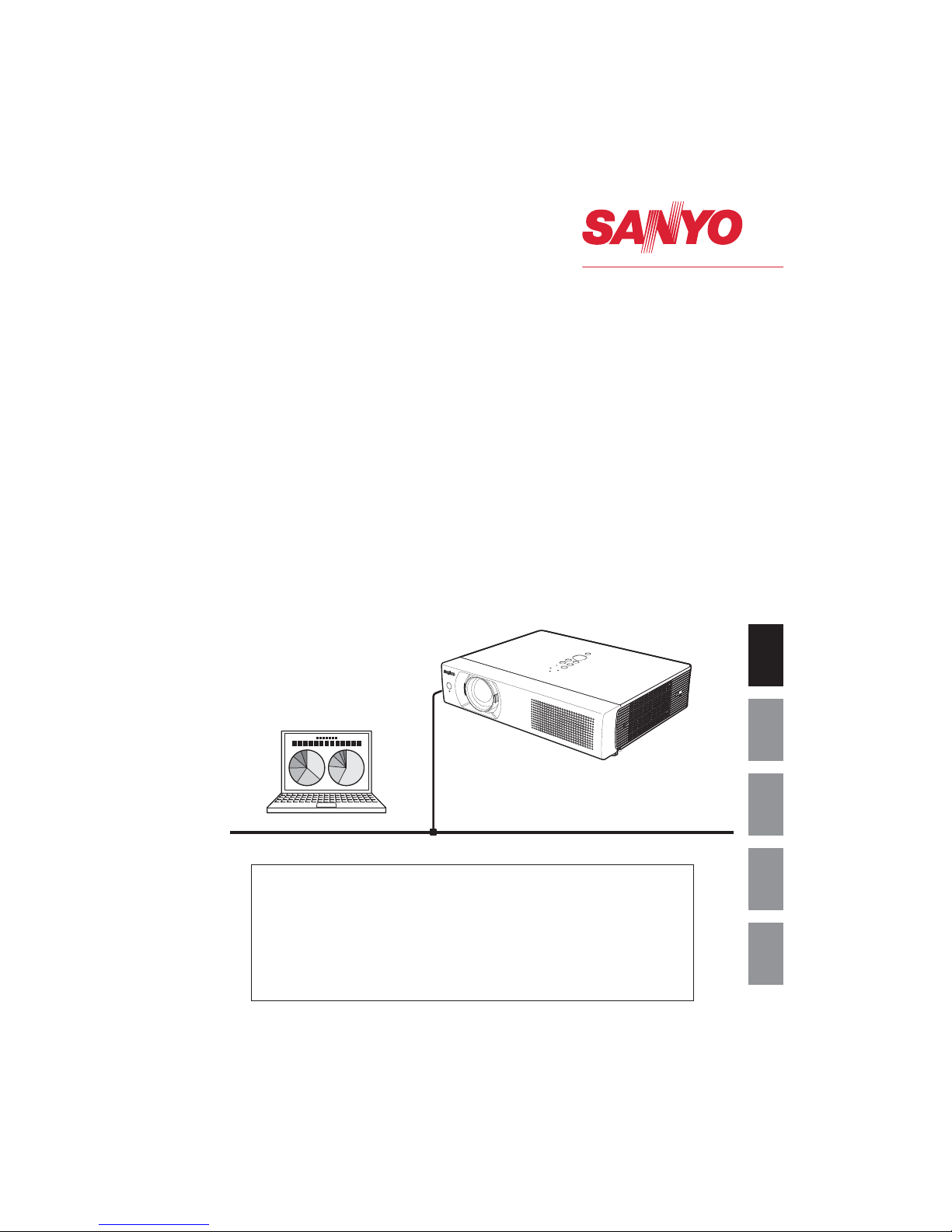
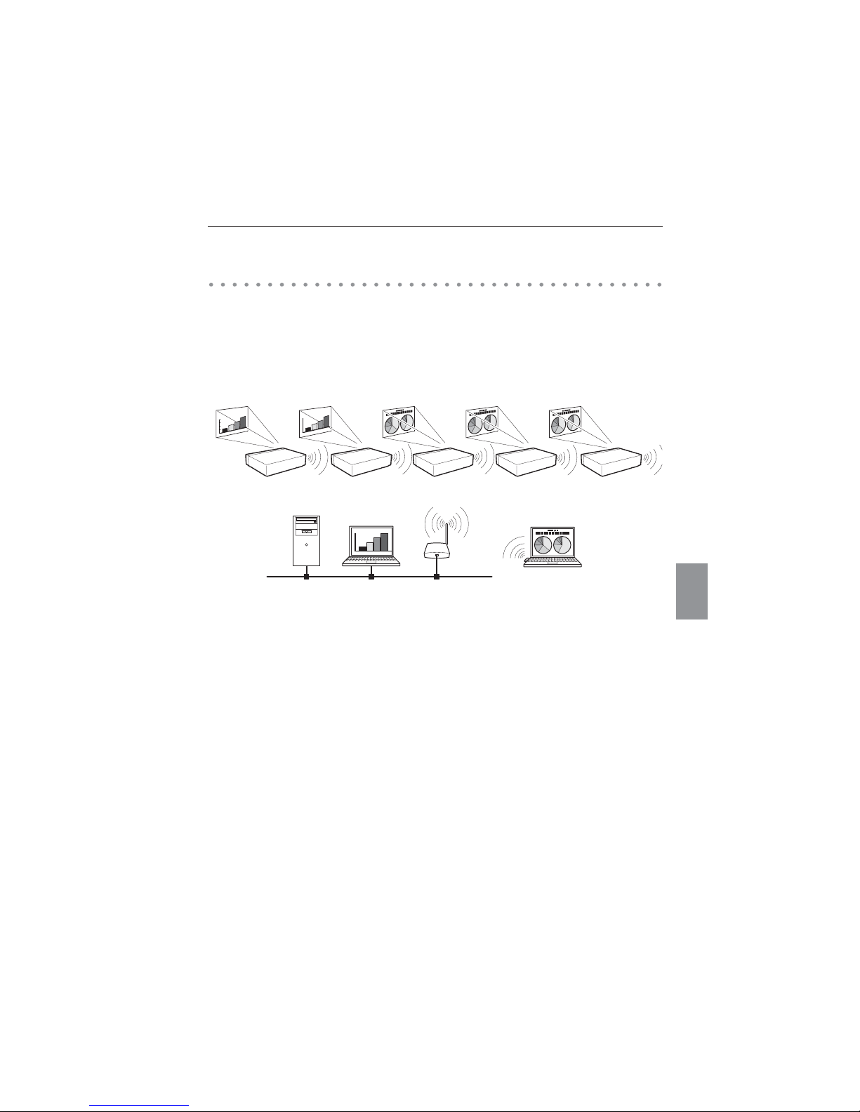
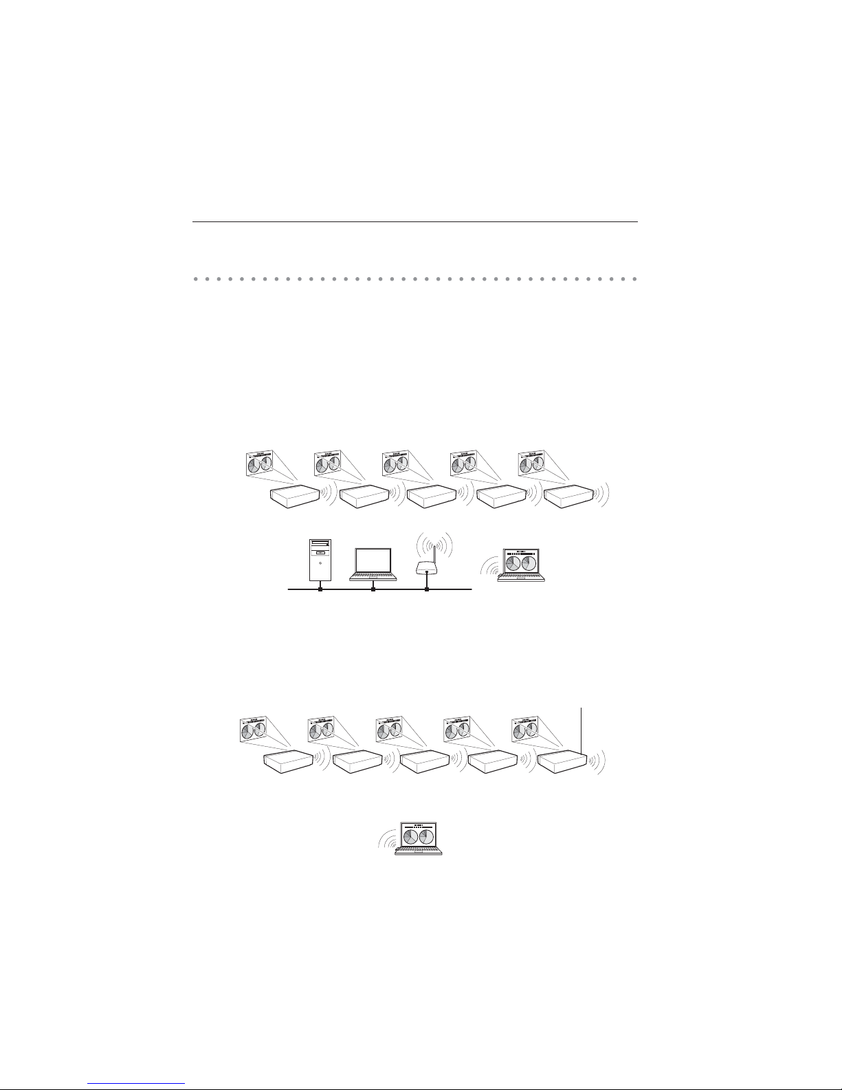
The illustration below shows an example of the projection via the LAN.
You can project the image on Computer (1) (Wired LAN connection), or Computer (2) (Wireless LAN
connection) through the selected projector .
.,.
.,3
/,.
/,3
0,.
.,.
.,3
/,.
/,3
0,.
.,.
.,3
/,.
/,3
0,.
Access pointComputer (1)
Computer (2)
An example of the connection
12
Chapter 1 About LAN functions
NWireless LAN, Infrastructure Communication Mode
Access pointComputer (1)
Wireless communication mode
corresponded computer: Infrastructure
NWireless LAN, AdHoc Communication Mode
Communication mode between Wireless LAN equipment.
(Communication mode via SSID/ESSID)
Wireless communication mode corresponded
computer: AdHoc
Computer (2)
Network Projector
Wireless communication mode :AdHoc
Communicate over an access point between Wired LAN equipment and Wireless LAN equipment. Or,
communicate over an access point among multiple Wireless LAN equipment. Wireless LAN equipment
will select an access point to communicate SSID/ESSID modes. These communication modes are used
when both Wireless LAN and Wired LAN are used in the same network environment.
LAN connection modes
Connection modes differ depending on the LAN and computer environments.
Connect appropriately for each environment.

13
English
NWired LAN Communication Mode
Communicate via the LAN line.
Computer(1) Computer(2) Computer (3)
3 Operate the computer mouse with the remote control.
When the projector’s remote control employs mouse operating function, you can operate
the computer by the remote control which is provided with the projector. To use the remote
control, point to the projector. You do not need to connect the USB cable to operate the
computer mouse.
(For details about the remote control operation, refer to the owner’s manual of the projector.)
LAN connection modeds

14
Chapter 1 About LAN functions

15
English
Chapter
15
English
This chapter describes how to install the Network
Capture 4 software and how to set up the networks.
Chapter
2
2. Setup procedures

16
Chapter 2 Setup procedures
To use the projector via the networks, follow the setup procedures below.
STEP 1
Install the software on computers.
Install the software recorded in CD-ROM on each computer which will be operated.
Read following pages of this chapter to install.
STEP 2
Select Wired LAN or Wireless LAN then connect the
LAN and set the configuration.
Decide depending on the LAN environment.
Wired LAN............ Refer to “4. Wired LAN Configurations” (p.25–31).
Wireless LAN....... Refer to “5. Wireless LAN Configurations” (p.33–42).
Detailed LAN configurations need to be done with a browser later.
First, complete the Wired or Wireless LAN connection between computers and
projectors, then start browser configurations.
“6. Basic setting and operation” (p.43–62).
STEP 3
Network Configuration has completed.
Follow each chapter to project an image and operate the projector.
NOperate and manage the projector “7. Controlling the projector” (p.63-84)
“Projector Power status and check” (p.64)
“Controls” (p.66)
“PC adjustment” (p.70)
“Setting up the projector” (p.71)
“Timer setting” (p.74)
“Projector information” (p.77)
“Multi-control” (p.79)
NProject an image on the computer “8. Network capture functions" (p.85-108)
“Use of real time capture” (p.89)
“Use of rnetwork communication” (p.94)
“Moderator function” (p.103)
NProject an image on a network server “9. Network viewer functions” (p.109-126)
“Create the image files” (p.110).
“Create the programe files” (p.115).
“Project the image with network viewer function” (p.120)
17
English
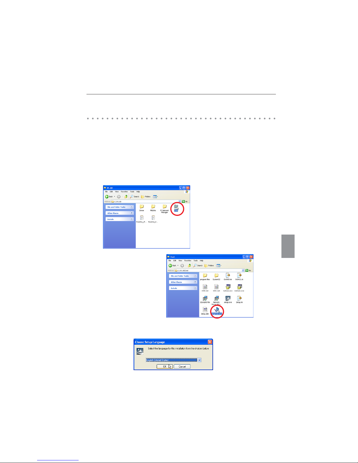
Installing the software
It is required to install the software into your computer to use the Network Capture function . Please
install the software as follows.
Note: To install the software into the computer with Windows 2000, Windows XP or
Windows Vista, you should logon as administrator. Before installation, make sure that
the other applications are closed, otherwise proper installation cannot be made.
Network Viewer & Capture 4 installation
1 Set the supplied Network Viewer & Capture 4 CD-ROM into the CD-ROM drive of your computer.
Double click SetupTool.exe icon in the "Tool" folder in the CD-ROM.
2 Select "English [United States]" from the pull-down menu on the "Choose Setup Language" window
and click OK button to start installing and then follow the installation wizards.
Installing the software
18
Chapter 2 Setup procedures
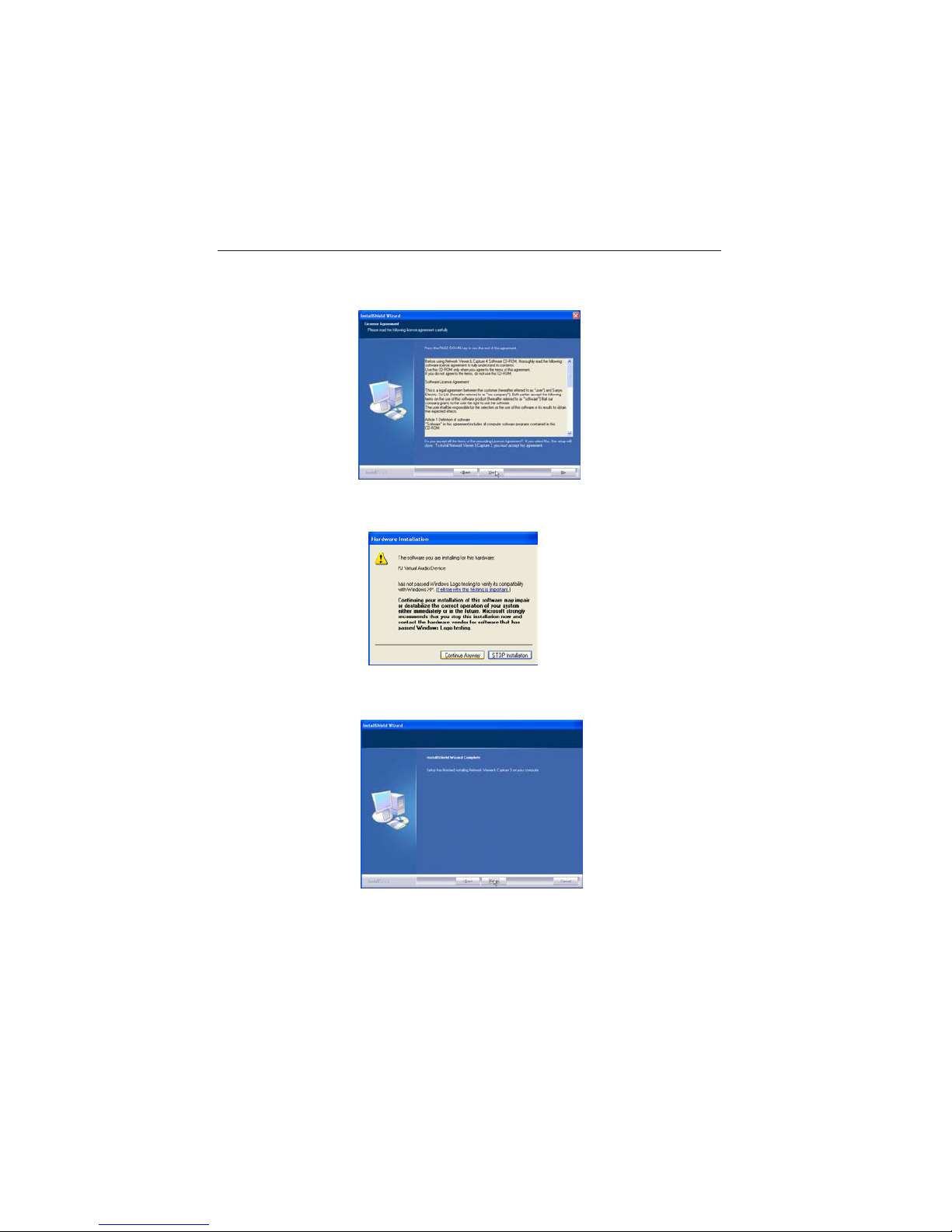
As the "License Agreement" will appear, read contents carefully and click Yes button if you agree to
the license agreement to proceed with installing.
During the installation, following window may appear, click Continue Anyway button.
3 Click Finish to complete the installation.
19
English
Installed software
The following 3 softwares are installed on your computer.
L Network Capture 4:
Captures the displayed image and the sound of the computer and serves them to the projector via
the network.
L Network Viewer 4 (File Converter 1):
Converts to the JPEG*1 data format which can be projected with the projector from the JPEG,
bitmap and Power Point files.
L Network Viewer 4 (Program Editor) :
This is a tool to make the program which has a function to specify and order the projecting JPEG
image data stored in the file servers.
* To uninstall thes e software, use "Add/R emove Program" from the control panel.
*1 This product supports the JPEG image format. This file is needed to convert to the optimized JPEG file by
using the File Converter 1 software previously. Refer to the item "Creating the available data [Network Viewer
4]"(p.110) about data converting for the projection.
File Converter 2 installation
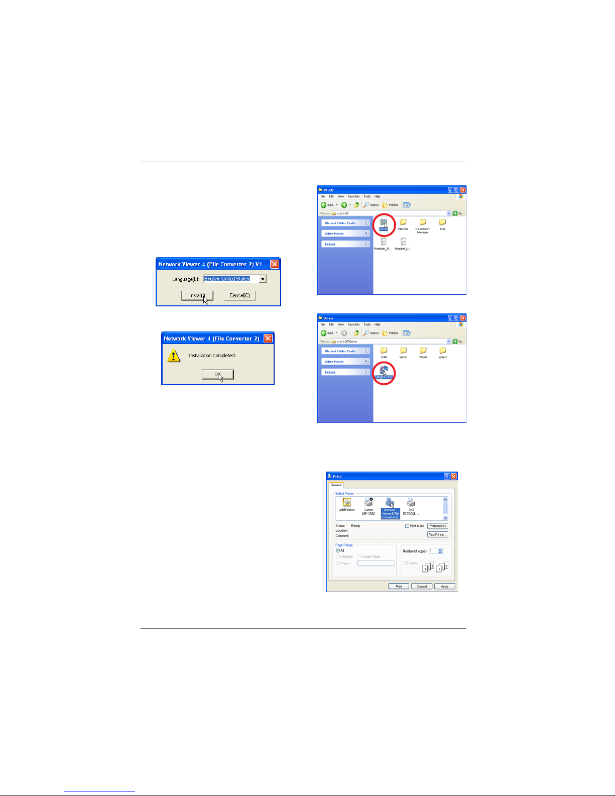
20
Chapter 2 Setup procedures
File Converter 2 installation
1 Set the supplied Network Viewer & Capture 4
CD-ROM into the CD-ROM drive of your computer.
Double click SetupDrv.exe icon in the "Driver"
folder in the CD-ROM.
2 Select "English [United States]" from the pull-down
menu on the language selection window and then
click Install button to start installing.
Installed software and places
Network Viewer 4 (File Converter 2) is installed in the
"Printers and Faxes" folder in the "Control Panel".
L Network Viewer 4 (File Converter 2):
This is a kind of the printer driver to convert to the
JPEG data optimized to project by the projector from
any of the documents created by the application
software.
* To uninstall Network Viewer 4 (File Converter 2), just delete the "Network Viewer 4(File Converter 2)" icon from the
"Printers and faxes" folder.

21
English
Chapter
21
English
Chapter
3. Names and functions of the operation
screen
This chapter describes the functions of each part of the
operation screen.
3

22
Chapter 3 Names and functions of the operating screen
Turn on the projector and select either “Wired” or “Wireless” from the input menu of the projector.
The “Please wait...” message will be displayed on the screen. After short time, the network connection
standby display screen will appear as below. While the “Please wait...” message is shown, you cannot
operate the projector.
Network connection standby display
Network Connection Standby Display
23
English
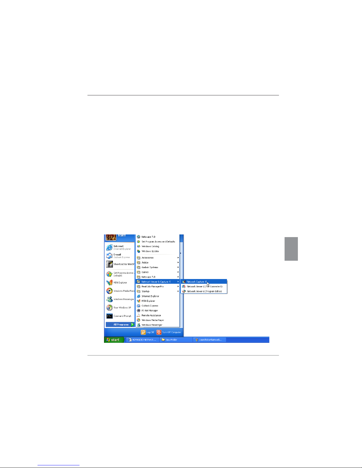
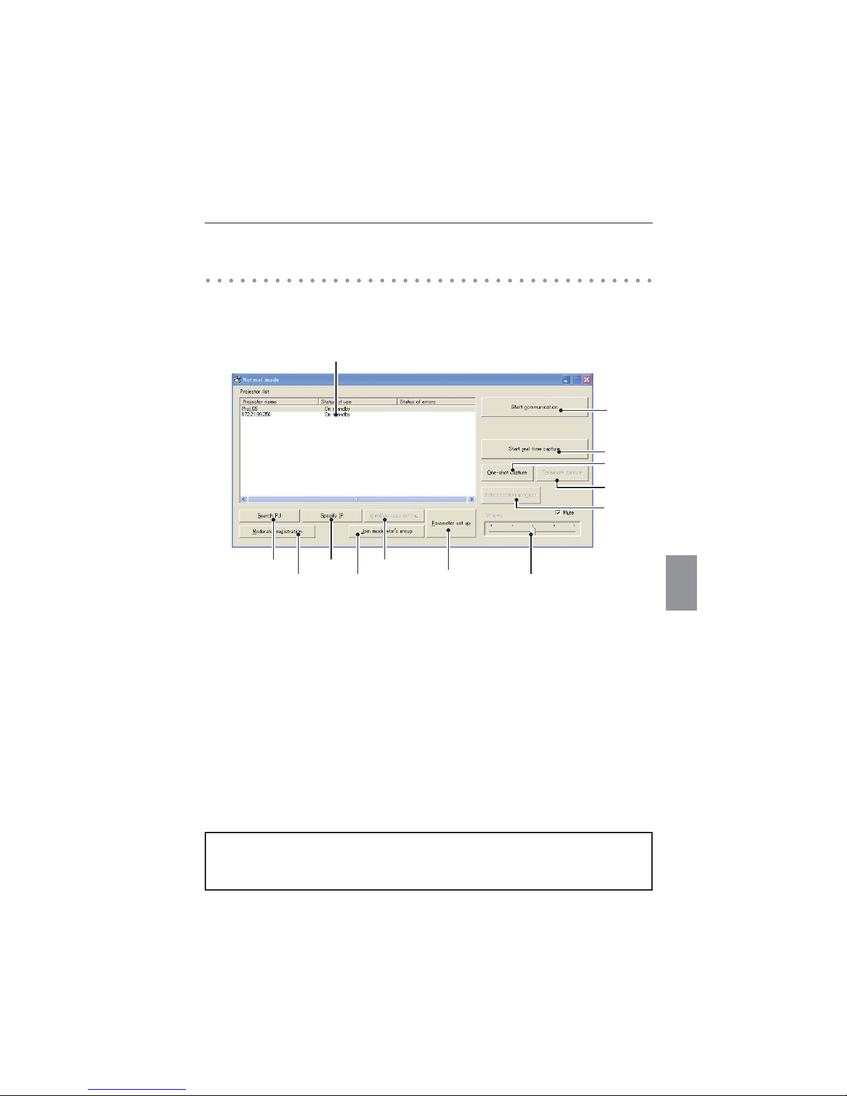
This software is to project the computer screen via the networks.
Select "All Programs" from the start menu --> Network Viewer & Capture 4" -->
"Network Capture 4", then following screen will appear. Then the program will start.
Parts Names and Functions of the Screen
DSearch PJ button
Search the projector connected to the networks.
JSpecify IP button
When connected to a different segment network, the projector can not be retrieved automatically.
In that case, press this button, and then, the "Search specified IP address" window appears, and
enter the IP address directly to specify the projector.
8Network Projector List
Display all the projectors connected to the networks.
Show unoccupied projector as “On standby” and occupied projector as “Real time capturing” or "In
One-shot mode". When registered in a moderator’s group, "On Moderator mode" will be shown.
The indication of the status of use with "#" indicates that your computer is now using the network
capture function.
After double-clicking on a projector, the web browser gets activated and the projector setup screen
will be displayed.
Network Capture 4 window
D J
B
<
8
E
G
L
H
Network Capt ure 4 window
Note on Windows Vista
When you use the Network Capture 4 software with Windows Vista, the warning dialog "User account
control" will appear. In that case, click Allow button to use it.
24
Chapter 3 Names and functions of the operating screen
EStart communication button
Enter the Communication mode, and then , the capture edit window starts. The selected projector
shows the capture edit window.
GStart real time capture button
Capture (Project) the computer screen in real time. After the execution of "Start real time capture",
the application window disappears.
LTerminate capture button
Terminate the real time capture and the One-shot capture.
HOne-shot capture button
Copy and capture (project) the computer screen without modification. After the execution of Oneshot capture, the application window disappears.
<Wireless easy setting button
Configure the Wireless LAN setting just by clicking this button. (The setting will be stored as AdHoc
system) For details, refer to "5. Wireless LAN configurations"-->"Easy wireless setting" (p.39). To
restore the easy setting, press the Wireless easy setting button.
B Moderator registration button
Register a computer user as a moderator.
Join moderator's group button
Join the moderator's group which is selected in the Network Projector list. It is not available if there
is no moderator registered.
Parameter setup button
Activate the parameter setup window, and execute the connections setting, the image setting, and
the moderator's function setting. For detail, refer to "Parameter set up" (p.88).
Select capturing object button
It is possible to designate the window to capture individually. This button is disabled by default,
so the full screen is captured. It is possible to change the capturing object function setting at
parameter settings. For detail, refer to "Parameter set up" (p.88).
Volume adjust slider and Mute check box
Adjust the audio output from the real time capturing computer. The mute check box is checked by
default.
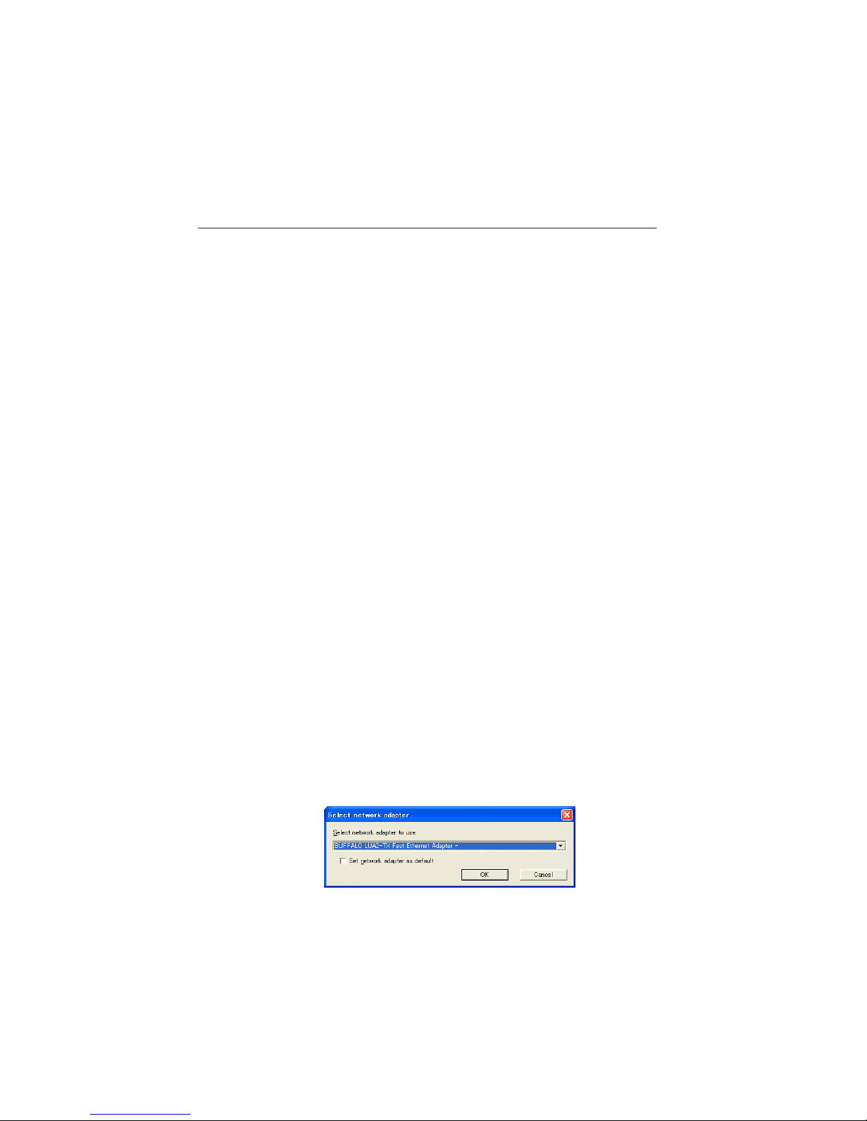
Using the multiple network adaptors
When your computer provides multiple network adaptors, the network adaptor selecting window
will appear each time the Network Capture 4 software starts. Select a network adaptor and check
the "Select a network adaptor as default" and the click OK. To change the setting, refer to the item
"Parameter set up" (p.88).

25
English
Chapter
25
English
Chapter
4
4. Wired LAN configurations
This chapter describes the preparation for Wired
LAN setting with projectors and how to set the LAN
environment.
26
Chapter 4 Wired LAN configurations
SD
Setting Procedure
Setting procedures and contents differ depending on the LAN installation location.
When installing, consult your system administrator to set up the LAN appropriately.
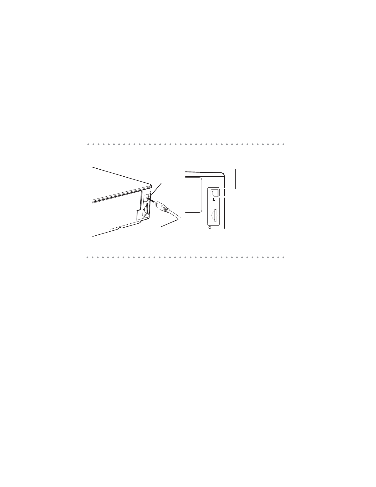
Connect the LAN cable to the LAN connection terminal of the projector.
Network environment settings
Set the Wired LAN network through the projector menu.
Detailed network settings will be made with browser. Refer to “6. Basic setting and operation” (p43-62).
First, complete the settings described in this chapter before performing steps in “6. basic setting and
operation.”
1. Turn on the projector and select “Wired” from the input menu of the projector.
The projector’s Link Lamp will be on and the Access Lamp will start to blink. If the “Wired setting” is
“Off”, it will not blink. Follow step 2 and 3 to blink the lamp.
2. Select “Wired Setting” in the projector menu, and press SELECT button.
Select similar LAN environment among LAN1, 2 and 3 with the Point buttons. (LAN1, 2, and 3
are the factory default setting environments. You can select three different environment among
setting LAN1–3. For each setting, refer to the chart on page 31.)
When selecting “Off” in the “Wired setting”, the LAN connection will be cut off. Use the function
when disconnecting the projector from the network.
3. Press the Point button then the “Please wait...” message will appear and switching operation will
start. Switching will take a while and after completing the operation, the “Ready for use” message will
appear. During the switching period, the projector cannot be operated.
Connecting to the LAN line
LAN Cable
LAN Connection
Terminal
Speed Lamp (Green)
Light according to the
speed of the connected
network.
10 Base-T.........Off
100 Base-T...... On
* When the LAN setting is “Off”, the two lamps
will not be on.
LINK/ACT Lamp (Orange)
Light or blink orange when
the projector is connected
to the network.
27
English
4. Press SELECT button.
LAN setting screen will appear and selected LAN settings will be displayed. Adjust each item to the
setting environment. Consult your system administrator about the detailed settings.
Adjust the figures with the Point ! buttons and move among the items with the Point
buttons.
5. After completing all the settings, select “Set” and press SELECT button. Now, all procedures have been
done. To cancel the adjusted settings, select "Cancel" and press SELECT button.
To confirm whether the settings are correct, follow the procedures described from the next page.
You can confirm the LAN settings you have made from “Network Information” (p.30). In such cases
that the LAN cannot be connected, see this screen.
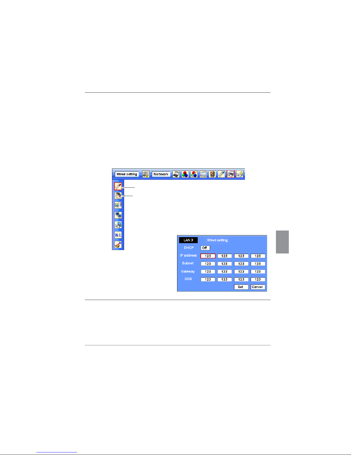
Wired setting
Wired LAN setting screen (Example)
Network PIN code
Item Description
DHCP..........................Sets DHCP function On or Off. When you setup the network setting manually, select "Off". When
it set On, IP address, Subnet, Gateway and DNS are automatically set according to your network
environment *
1
.
IP address .................Sets IP address of the projector
Subnet.......................Sets Subnet mask. Normally sets 255.255.255.0
Gateway*2.................Sets IP address of the default gateway (Router)
DNS*
2
..........................Sets IP address of the DNS server.
*1 Set "On" only when the DHCP server is available on your network environment.
*2 Set [255.255.255.255] if the network does not provide the gateway (router).
*3 Set [255. 255.255. 255] if you d o not use t he func tion E-M ail aler t.
* While the network communication finction (p.85) or moderator function (p.103) is to be executing, the menus
"Network capture", "Network viewer" and "Memory viewer" are displayed in gray.
Network environment setting
28
Chapter 4 Wired LAN configurations
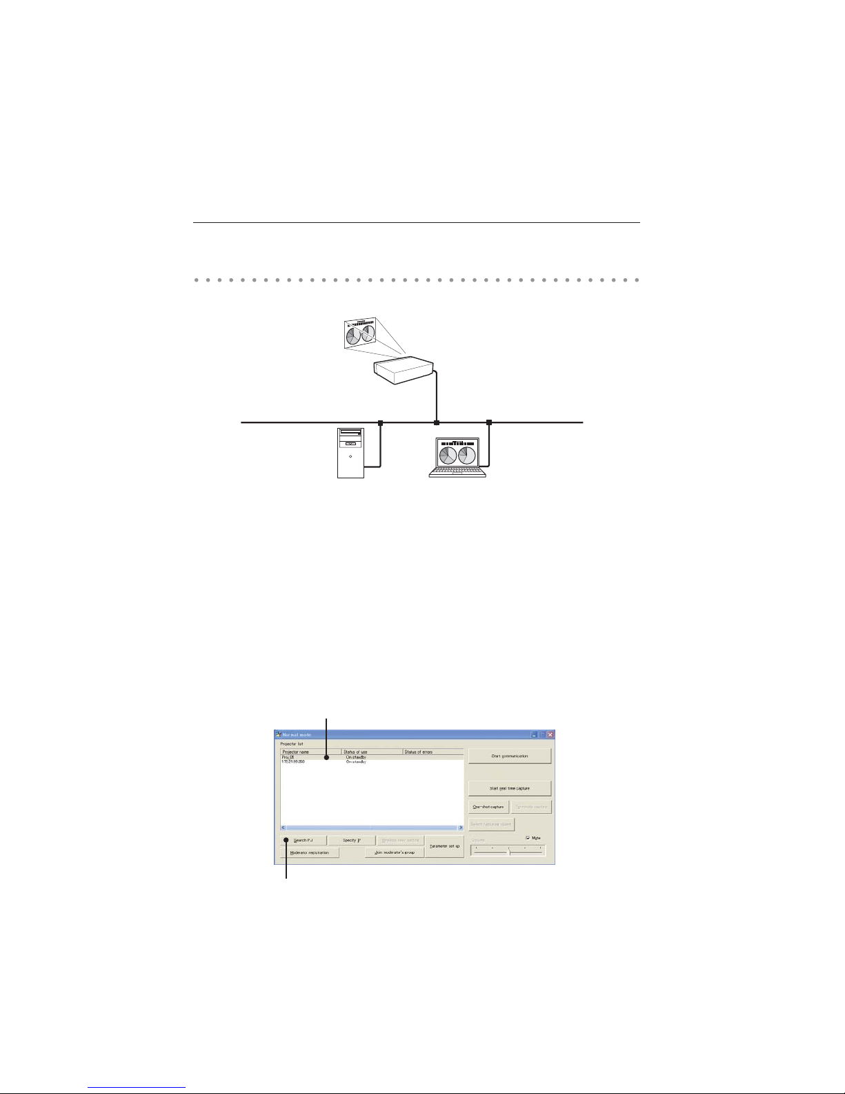
Network Capture screen
Confirming the operation
Confirm that the projector has connected to the LAN properly.
1. Activate “Network Capture 4” which is installed into the computer connected to the LAN .
2. After “Searching projector” message appears, the name of the projector* appears on the Network
Projector List, then the network setting has completed properly.
When the name of the projector does not appear and error screen appears, the network has
not connected yet. Try searching again with the Search PJ button. If error screen appears again,
reconfirm the LAN setting. When the projector is set in the location separated by the router, see next
page.
When Firewall function (Anti-virus software) is effective, network projector may not be found. In that
case, disable the Firewall function and try searching again.
3 If the projector is named, the name will be displayed. The name can be set with the following
procedures in “6. Basic setting and operation” “Initial setting” (p48) . If the projector is not named,
IP address of the projector will be displayed.
Network Projector List
Search PJ button
29
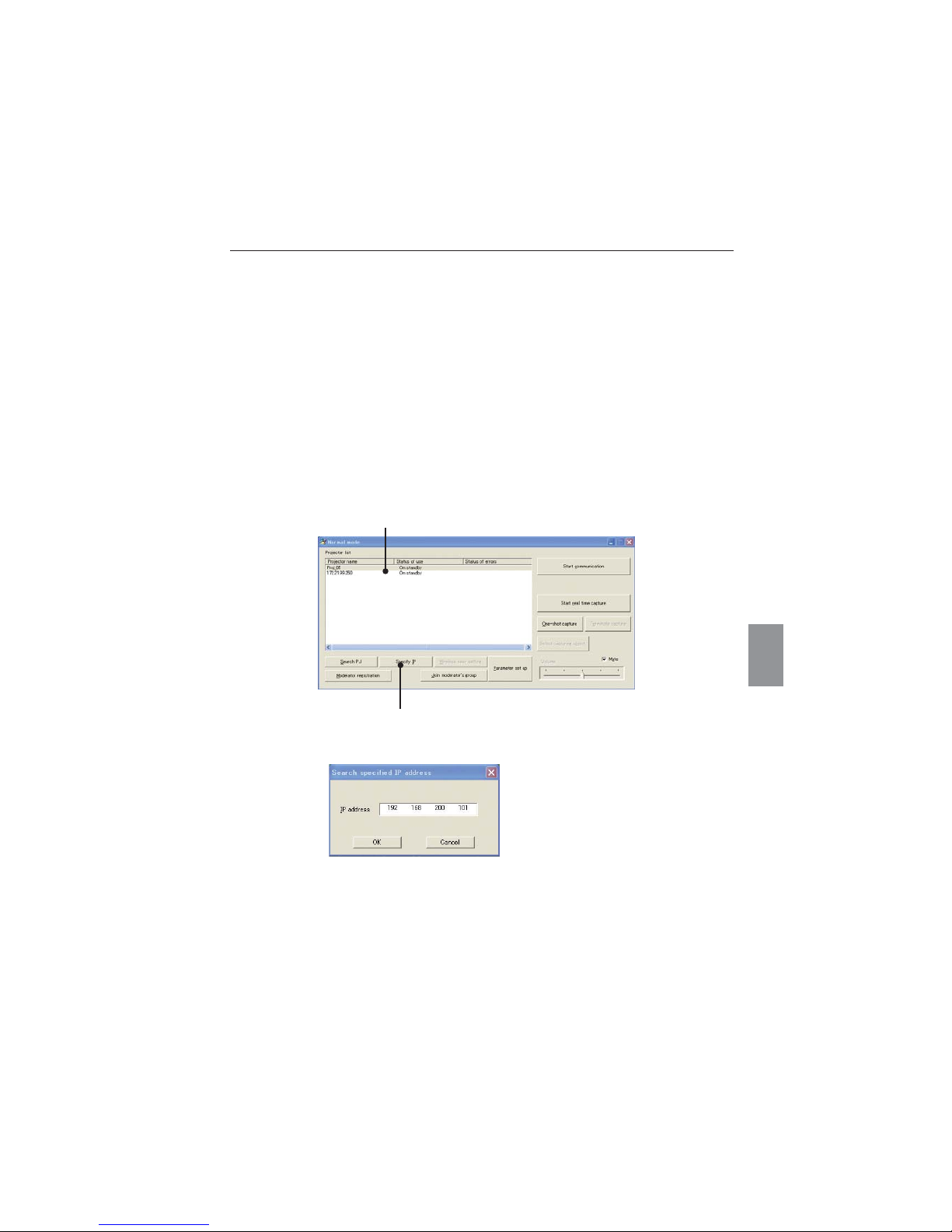
English
When set up the projector in the location separated by the router and the segment is different;
Projector will not be found nor displayed. In that case, the projector needs to be searched directly by
the IP address.
1. Press Specify IP button. "Search specified IP address" window appears.
2. Enter the IP address of projecor and Click OK. Then, the projector will be added on the Network
Projector List of the application window.
"Search specified IP address" window
Specify IP button
Network Projector list
Confirming the operation
30
Chapter 4 Wired LAN configurations
Network information
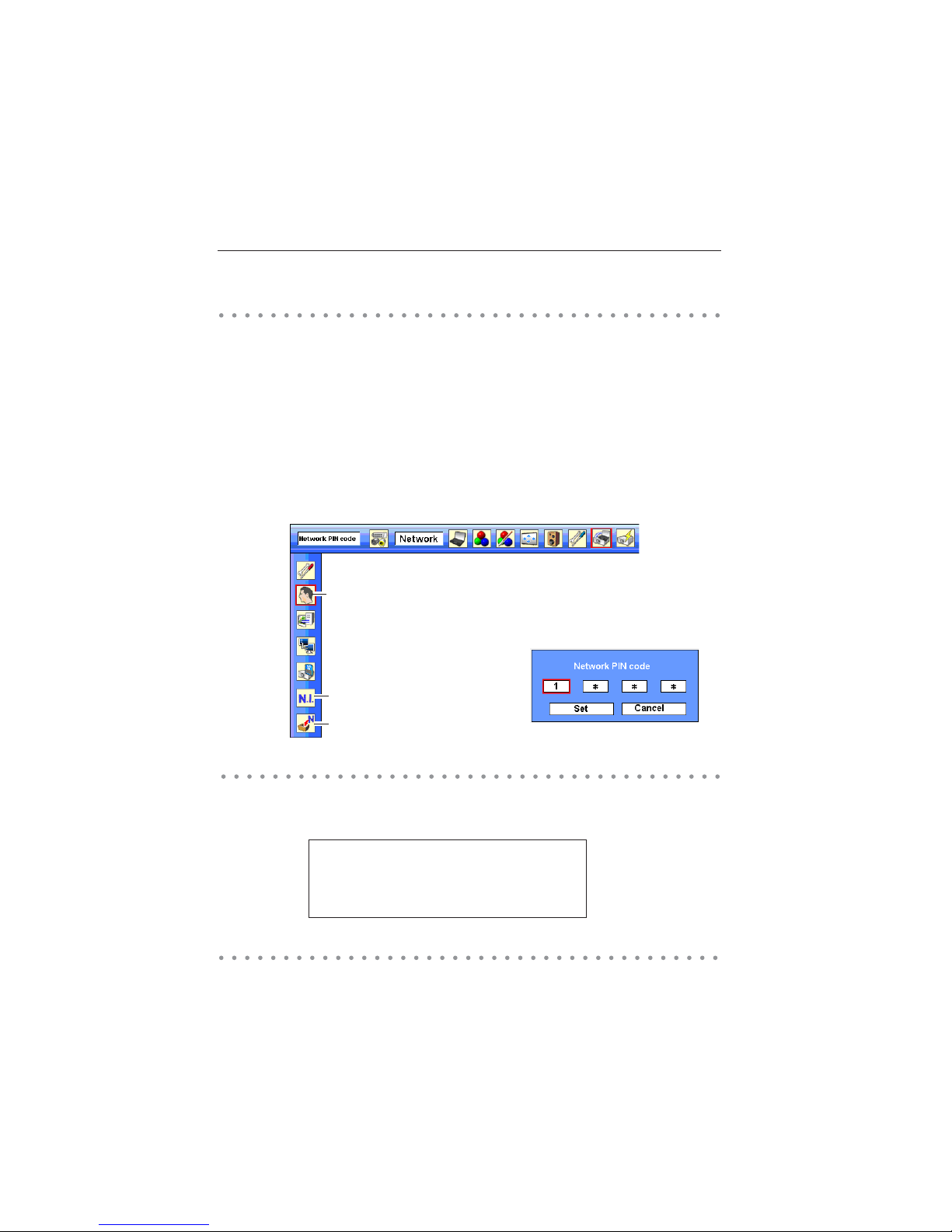
The Network PIN code is to restrict the access from the networks to the projector.
After setting the Network PIN code, you need to enter it to operate the projector via the networks.
1. Select Network PIN code menu, and press SELECT button.
The Network PIN code screen will appear.
2. Set the Network PIN code.
Set the figures with the Point ! buttons and move to the next items with the Point buttons.
Select “Set” and press SELECT button to set. To cancel the preset Network PIN code, select “Cancel”.
When you do not want to set the Network PIN code, set
"0000".
It is recommended to set the Network PIN code if you use the projector via the networks. You can also
change the Network PIN code. See “6. Basic setting and operation” “Initial setting” “Network PIN
code setting” (p49).
Wired factory default
Select Network information from the projector menu and press SELECT button to show LAN setting
environment of the currently selected projector. (The description below is an example and different
from what will be shown.)
Select “Wired factory default” from the projector menu and press SELECT button. All the LAN settings will
go back to the factory default settings. For details, refer to “Wired LAN factory default settings” (p.31).
Wired factory default
Network information
Network PIN code
(See the menu above.)
(See the menu above.)
Network PIN code
Network PIN code screen
Network information
MAIN PROGRAM: V1.000
MAC ADDRESS: 08007B650056
IP ADDRESS: 172.21.95.202
 Loading...