

Page 1
FILE NO.
SERVICE MANUAL
Multimedia Projector
Model No. PLC-XL45
U.S.A. Canada
Europe, U.K
Original Version
NOTE: Match the Chassis No. on the unit's back cover
with the Chassis No. in the Service Manual.
If the Original Versi on Service Manua l
Chassis No. does not match the unit’s, addi-
tional Service Literature is required. You must
refer to “Notices” to the Original Service Manual
prior to servicing the unit.
PRODUCT CODE
1 122 373 00 (KZ6AC)
1 122 374 00 (LZ6AC)
1 122 374 02 (LZ6CC)
Chassis No. KZ6-XL4500
REFERENCE NO. SM5110900-00
Page 2

Contents
Safety Instructions ......................................................... 3
SAFETY PRECAUTIONS ........................................... 3
PRODUCT SAFETY NOTICE .................................... 3
SERVICE PERSONNEL WARNING ..........................
Specifications ................................................................4
Circuit Protections .........................................................5
Thermal switch ........................................................... 5
Lamp cover switch ...................................................... 5
Fuse ............................................................................ 5
Warning temperature and power failure protection .... 6
Air filter care and cleaning .......................................... 6
Security Function Notice ................................................ 7
Lamp Replacement .......................................................8
Lamp replacement ...................................................... 8
How to reset Lamp Replace Counter ......................... 8
How to check Lamp used time ................................... 8
Mechanical Disassembly ............................................... 9
Optical Parts Disassembly ........................................... 13
Panel Type Check .................................................... 16
Adjustments ................................................................. 19
Adjustments after Parts Replacement ...................... 19
Electrical Adjustments ................................................. 23
Service Adjustment Menu Operation ........................ 23
Memory IC (IC1371) Replacement ........................... 23
Circuit Adjustments ................................................... 24
Test Points and Locations ........................................ 27
Service Adjustment Data Table ................................ 28
Chassis Block Diagrams .............................................. 39
Chassis over view ..................................................... 39
System control .......................................................... 40
Power supply & protection circuit ............................. 41
Fan control circuit ..................................................... 42
Troubleshooting ........................................................... 43
Indicators and Projector Condition ........................... 43
No Power .................................................................. 44
No Picture ................................................................. 45
No Sound .................................................................. 46
Control Port Functions ................................................. 47
System Control I/O Port Functions (IC301) .............. 47
I/O Expander Port Functions (IC1801) .................... 48
IIC Bus DA Converter Port Functions (IC3571) ....... 48
Waveform .................................................................... 49
Cleaning ......................................................................50
Projection Lens Cleaning .......................................... 50
IC Block Diagrams ....................................................... 51
Electrical Parts List ...................................................... 57
Electrical Parts Location ........................................... 58
3
Mechanical Parts List ..................................................79
Cabinet Parts Location ............................................. 79
Optical Parts Location .............................................. 80
Mechanical Parts List ............................................... 84
Diagrams & Drawings ..................................................A1
Parts description and reading in schematic diagram ...A2
Schematic Diagrams ...................................................A3
Printed Wiring Board Diagrams .................................A11
Pin description of diode, transistor and IC .................A15
Note on Sordering .....................................................A16
-2-
Page 3

Safety Instructions
SAFETY PRECAUTIONS
WARNING:
The chassis of this projector is isolated (COLD) from AC line by using the converter transformer. Primary side
of the converter and lamp power supply unit circuit is connected to the AC line and it is hot, which hot circuit is
identified with the line ( ) in the schematic diagram. For continued product safety and protection of personnel injury, servicing should be made with qualified personnel.
The following precautions must be observed.
1: An isolation transformer should be connected in
the power line between the projector and the AC
line before any service is performed on the projector.
2: Comply with all caution and safety-related notes
provided on the cabinet back, cabinet bottom, inside
the cabinet or on the chassis.
3: When replacing a chassis in the cabinet, always
be certain that all the protective devices are
installed properly, such as, control knobs, adjustment covers or shields, barriers, etc.
DO NOT OPERATE THIS PROJECTOR WITHOUT
THE PROTECTIVE SHIELD IN POSITION AND PR
OPERLY SECURED.
4: Before replacing the cabinet cover, thoroughly
inspect the inside of the cabinet to see that no stray
parts or tools have been left inside.
Before returning any projector to the customer, the
service personnel must be sure it is completely safe
to operate without danger of electric shock.
PRODUCT SAFETY NOTICE
Product safety should be considered when a component replacement is made in any area of the projector.
Components indicated by mark ! in the parts list and the schematic diagram designate components in which
safety can be of special significance. It is, therefore, particularly recommended that the replacement of there
parts must be made by exactly the same parts.
SERVICE PERSONNEL WARNING
Eye damage may result from directly viewing the light produced by the Lamp used in this equipment. Always
turn off Lamp before opening cover. The Ultraviolet radiation eye protection required during this servicing.
Never turn the power on without the lamp to avoid electric-shock or damage of the devices since the stabilizer
generates high voltages (15kV - 25kV) at its starts.
Since the lamp is very high temperature during units operation replacement of the lamp should be done at least
45 minutes after the power has been turned off, to allow the lamp cool-off.
-3-
Page 4

Specifications
Mechanical Information
Projector Type Multi-media Projector
Dimensions (W x H x D) 10.50" x 4.86" x 9.58" (320mm x 148mm x 292mm) (Not including adjustable feet)
Net Weight 7.1 lbs (3.2kgs)
Feet Adjustment 0˚ to 10.0˚
Panel Resolution
LCD Panel System 0.6" TFT Active Matrix type, 3 panels
Panel Resolution 1,024 x 768 dots
Number of Pixels 2,359,296 (1,024 x 768 x 3 panels)
Signal Compatibility
Color System
High Definition TV Signal 480i, 480p, 575i, 575p, 720p, 1035i, and 1080i
Scanning Frequency H-sync. 15 KHz~ 100 KHz, V-sync. 50 ~ 100 Hz
Optical Information
Projection Image Size (Diagonal) Adjustable from 60" to 80"
Projection Lens F 1.85 lens with f 8.1 mm ~ 27 mm with manual focus
Throw Distance 2.49’ - 3.38’ (0.76m - 1.03m)
Projection Lamp 200W
PAL, SECAM, NTSC, NTSC4.43, PAL-M, PAL-N
Interface
Video Input Jack RCA Type x 1
S-Video Input Jack Mini DIN 4 pin x 1
Audio Input Jacks RCA Type x 2
Computer Input 1 / Component Input Terminal Anlaog RGB (Mini D-sub 15 pin) Terminal X 1
Computer Input 2 / Monitor Output Terminal
Computer/ Component Audio Input Jack
Service Port Connector Mini DIN 8 pin x 1
USB Connector USB Series B receptacle x 1
Audio Output Jack Mini Jack (stereo) x 1 (Variable)
Anlaog RGB (Mini D-sub 15 pin) Terminal X 1 (In / Out switchable)
Mini Jack (stereo) x 1
Audio
Internal Audio Amp 1.0W RMS
Built-in Speaker 1 speaker, ø1.1" (28mm)
Power
Voltage and Power Consumption AC 100 ~ 120 V (3.2A Max. Ampere), 50 / 60 Hz (The U.S.A and Canada)
AC 200 ~ 240 V (1.6A Max. Ampere), 50 / 60 Hz (Continental Europe and The U.K.)
Operating Environment
Operating Temperature 41 ˚F ~ 95 ˚F (5 ˚C ~ 35 ˚C)
Storage Temperature 14 ˚F ~ 140 ˚F (-10˚C ~ 60 ˚C)
Remote Control
Battery AA or LR6 1.5V ALKALINE TYPE x 2
Operating Range 16.4’ (5m) / ±30˚
Dimensions 1.9”(W) x 0.87”(H) x 5.7”(D) (49mm x 22mm x 145.3mm)
Net Weight 3.53 oz (100 g) (including batteries)
Antitheft Alarm
Battery CR2 3V LITHIUM BATTERY x 1
● The specifications are subject to change without notice.
● LCD panels are manufactured to the highest possible standards. Even though 99.99% of the pixels are effective, a tiny
fraction of the pixels (0.01% or less) may be ineffective by the characteristics of the LCD panels.
This symbol on the nameplate means the product is Listed by Underwriters
Laboratories Inc. It is designed and manufactured to meet rigid U.L. safety standards against risk of fire, casualty and electrical hazards.
-4-
Page 5
Circuit Protections
This projector provides the following circuit protections to operate in safety. If the abnormality occurs inside the projector, it will automatically turn off by operating one of the following protection circuits.
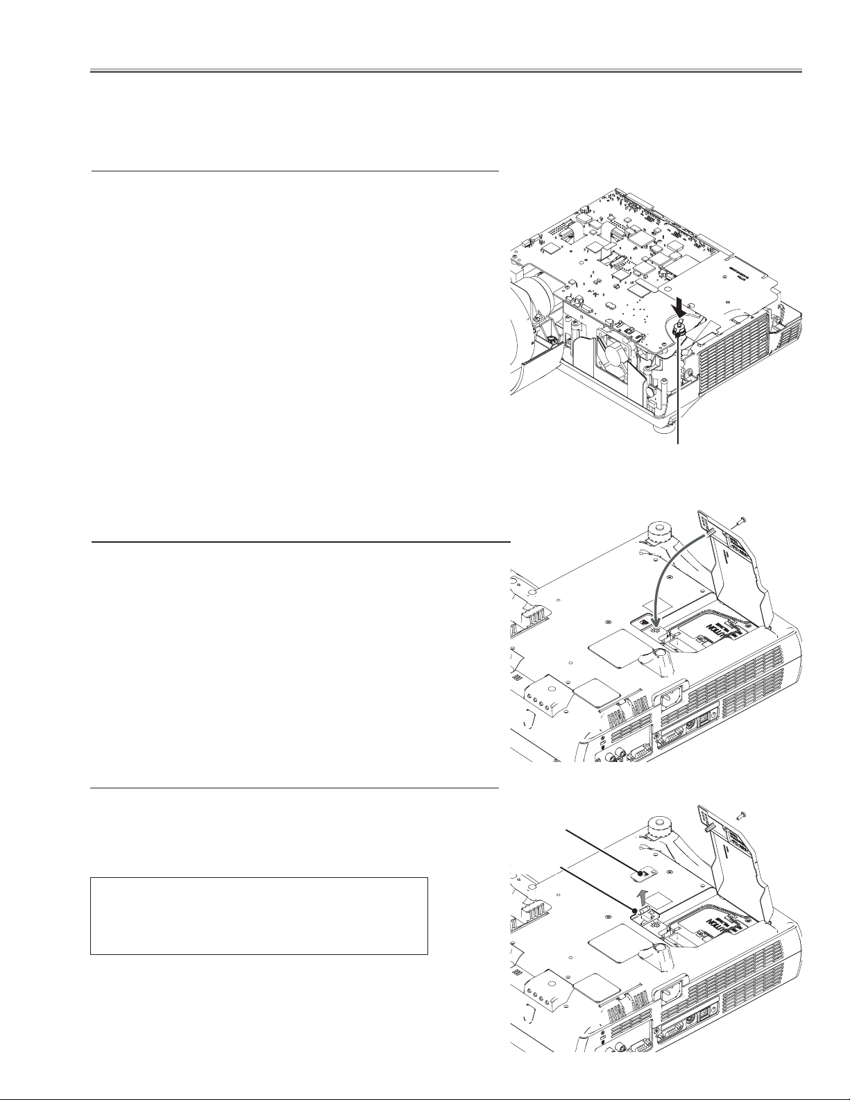
Thermal switch
There is the thermal switch (SW902) inside of the projector to detect
the internal temperature rising abnormally. When the internal temperature reaches near 105˚C, the thermal switch opens to stop the
operation of the power supply circuit.
The thermal switch cannot be reset itself automatically even if the
internal temperature becomes normal. Reset the thermal switch following to the below procedure.
How to reset the thermal switch
1. Remove the cabinet top, cabinet front and main board and then
remove the power box top cover.
2. Press the reset button on the thermal switch in the power box.
CAUTION:
Before press the reset button, make sure that the AC cord must be
disconnected from the AC outlet.
Thermal switch (SW902)
Lamp cover switch
The lamp cover switch (SW901) cuts off the drive signal to the lamp
circuit when the lamp cover is removed or not closed completely.
After opening the lamp cover for replacing the lamp ass’y, place the
lamp cover correctly otherwise the projector can not turn on.
Fuse
A fuse is located inside of the projector. When the POWER indicator
is not lightning, the fuse may be opened. Check the fuse as following steps.
The fuse should be used with the following type;
Fuse Part No.: 323 021 7804
TYPE T6.3AH 250V FUSE
LITTLE FUSE INC. TYPE 21506.3
Fuse cover
Fuse
How to replace the fuse
1. Remove the lamp cover and fuse cover as shown in figure.
2. Take the fuse out from the aperture, and replace the new one with
the specified type.
-5-
Page 6
Circuit Protections
Warning temperature and power failure protection
The projector will be automatically turned off when the internal temperature of the projector is abnormally high, or the
cooling fans stop spinning, or the power supplies in the projector are failed.
- If the WARNING indicator is flashing, it may detect the abnormal temperature inside the projector. Check the following possible causes and wait until the WARNING indicator stops flashing, and then try to turn on the projector.
- If the WARNING indicator lights red, it may defect the cooling fans or power supply circuits. Check fans operation
and power supply lines referring to the chapter “Power supply & protection circuit” in the Chassis Block Diagram
section.
Possible causes
- Air filters are clogged with dust particles. Remove dust from the air filters by following instructions in the “Air filter
care and cleaning” below.
- Ventilation slots of the projector are blocked. In such an event, reposition the projector so that ventilation slots are
not obstructed.
- Check if projector is used at higher temperature place (Normal operating temperature is 5 to 35 ˚C or 41 to 95˚F)
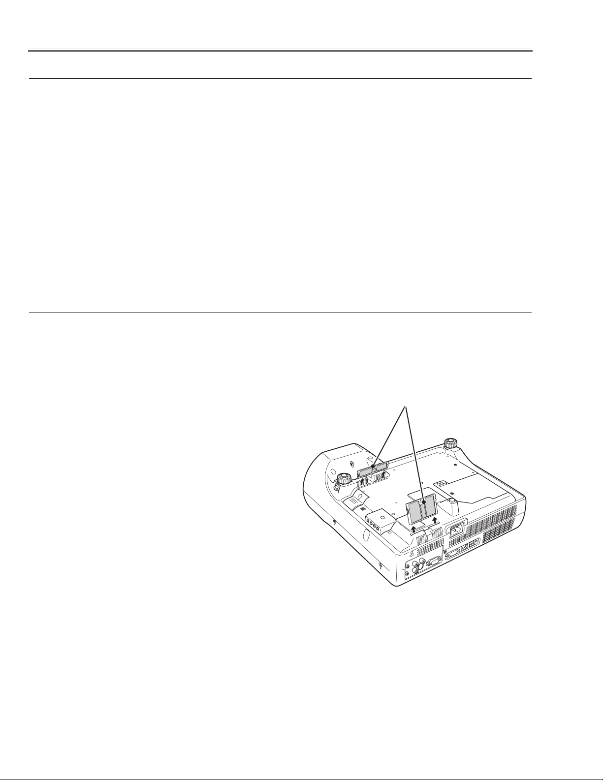
Air filter care and cleaning
Air filters prevent dust from accumulating on the optical elements inside the projector. Should the air filters become
clogged with dust particles, it will reduce cooling fans’ effectiveness and may result in internal heat build up and adversely affect the life of the projector. Clean the air filters following the steps below.
1. Turn off the projector, and disconnect the AC power cord
from the AC outlet.
2. Turn over the projector and remove the air filters by pulling
the latches upward.
3. Clean the air filters with a brush or rinse them softly.
4. When cleaning the air filters by rinsing, dry them well. Re-
place the air filters properly. Make sure that the air filters
are fully inserted.
Air filters
CAUTION:
Do not operate the projector with the air filters removed.
Dust may accumulate on the LCD panel and the projection
mirror degrading picture quality.
Do not put small parts into the air intake vents. It may result
in malfunction of the projector.
RECOMMENDATION:
We recommend avoiding dusty/smoky environments
when operating the projector. Usage in these
environments may cause poor image quality.
When using the projector under dusty or smoky conditions, dust may accumulate on a lens, LCD panels, or optical
elements inside the projector. This condition may degrade the quality of a projected image.
When the symptoms above are noticed, contact your authorized dealer or service station for proper cleaning.
-6-
Page 7

Security Function Notice
This projector provides security functions such as "Key lock", "PIN code lock" and "Logo PIN code lock". When the projector has set these security function on, you are required to enter correct PIN code to use the projector. If you do not
know the correct PIN code to the projector, the projector can no longer be operated or started. In this case, you must
reset those function first according to the resetting procedure described below and then check up on the projector.
Function Description
Locks operation of the top control or the remote control.
Key lock
PIN code lock
Logo PIN code lock
If the Key lock is enabled with top control lock, the projector can no longer be started.
Initial setting: Key lock function is disabled
Prevents the projector from being operated by an unauthorized person.
Initial code: “1234”
Prevents an unauthorized person for changing the
start-up logo on the screen.
Initial code: “4321”
Resetting procedure
1 Disconnect the AC power cord from the AC outlet.
2 As pressing the SELECT button on the projector, connect the AC power cord into an AC outlet again. Keep
pressing the SELECT button until the POWER indicator lights continuously.
This is complete the resetting of the security function. The PIN code lock and Logo PIN code lock are reset as
the initial PIN code at the factory and the Key lock function is disabled.
Please refer to the owner's manual for further information of the security functions.
-7-
Page 8
Lamp Replacement
Counter
Projector 525H
Lamp
Normal 150H
Eco 375H
Corresponding value 675H
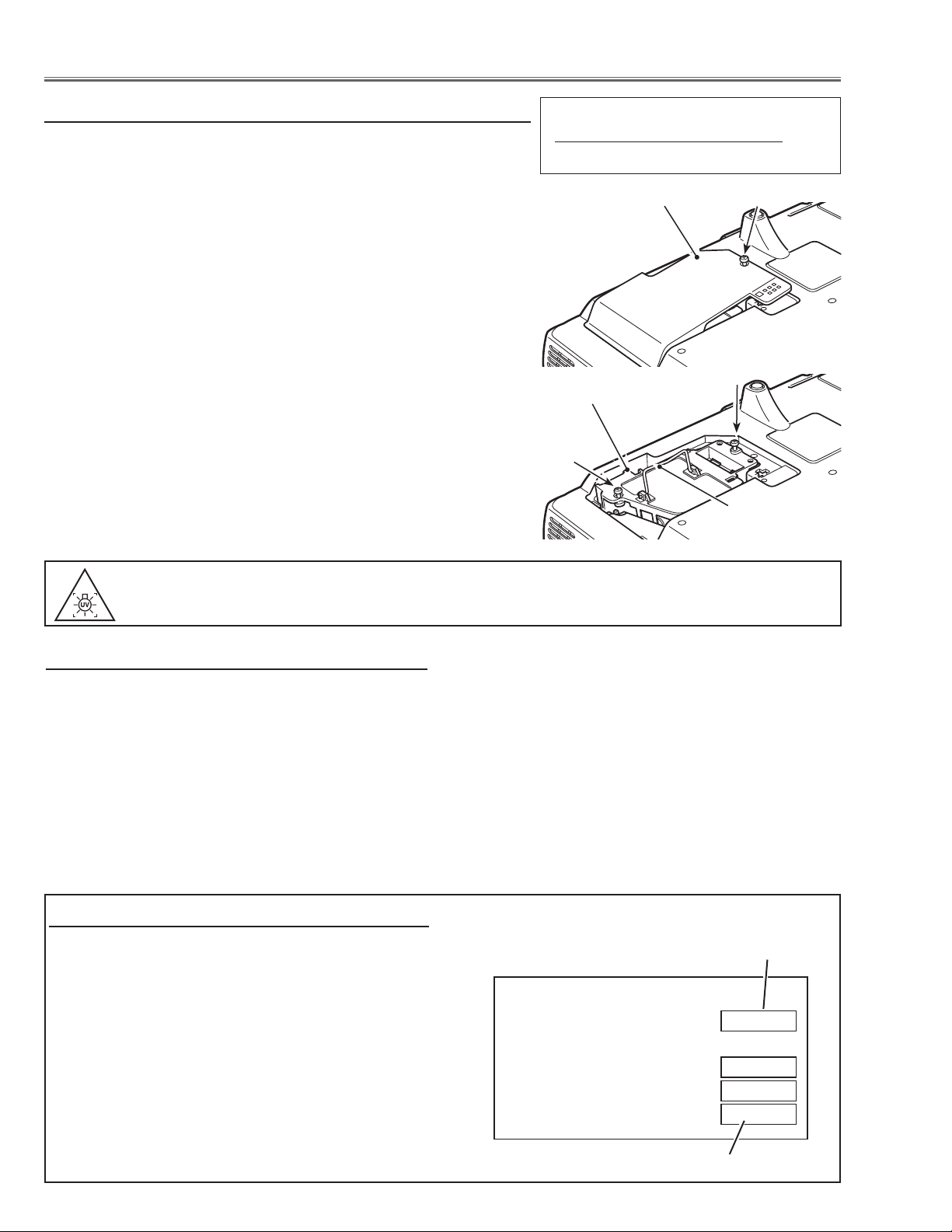
Lamp replacement
WARNING:
- For continued safety, replace with a lamp assembly of the same type.
- Allow the projector to cool for at least 45 minutes before you open the
lamp cover. The inside of the projector can become very hot.
- Do not drop the lamp module or touch the glass bulb! The glass can
shatter and cause injury.
Procedure
1 Turn off the projector and disconnect the AC cord.
2 Remove 1 screw with a screwdriver and remove the lamp cover.
3 Loosen 2 screws and pull out the lamp assembly by grasping the
handle.
4 Replace the lamp with a new one and tighten the 2 screws back into
position. Make sure that the lamp is set properly. Replace the lamp
cover and tighten the screw.
5 Connect the AC cord to the projector and turn on.
6 Reset the lamp replacement counter, see below explanation.
Note
- The projector cannot be turned-on with lamp cover removed, because
when the lamp cover is removed, the lamp cover switch is also released to switch off the lamp circuit.
ORDER REPLACEMENT LAMP
Type No. Service Parts No.
POA-LMP106 610 332 3855
Lamp Cover
Lamp
Screw
Screw
Screw
Handle
WARNING : TURN OFF THE UV LAMP BEFORE OPENING.
USE UV RADIATION EYE AND SKIN PROTECTION DURING SERVICING.
How to reset Lamp Replace Counter
1 Turn the projector on, press the MENU button and the
On-Screen Menu will appear. Press the 7 or 8 but-
ton to move the red frame pointer to the Setting Menu
icon.
2 Press the d button to move the red frame pointer to
the Lamp counter reset item and then press the SELECT button. Select "Reset" and press the SELECT
button. The message "Lamp replace counter Reset?"
is displayed. Move the pointer to [Yes] and then press
the SELECT button.
* Refer to owner's manual for further information.
How to check Lamp used time
The LAMP REPLACE indicator will light yellow when
the total lamp used time (Corresponding value) reaches
3000 hours. This is to indicate that lamp replacement is
required.
The total lamp used time is calculated by using the below expression,
Total lamp used time = Teco + Tnormal x 2
Teco: used time in the Eco mode
Tnormal : used time in the Normal mode
You can check the lamp used time following to the below
procedure.
1 Press and hold the ON-OFF button for more than 20
seconds.
Recommendation
Should the air filter become clogged with dust particles,
it will reduce the cooling fan’s effectiveness and may result in internal heat build up and short lamp life. We recommend cleaning the air filter after the projection lamp
is replaced.
Refer to “Air Filter Cleaning”.
2 The projector used time and lamp used time will be
displayed on the screen briefly as follows.
Projector used time
Total lamp used time
-8-
Page 9
Mechanical Disassembly
Mechanical disassembly should be made following procedures in numerical order.
Following steps show the basic procedures, therefore unnecessary step may
be ignored.
Caution:
The parts and screws should be placed exactly the same position as the original
otherwise it may cause loss of performance and product safety.
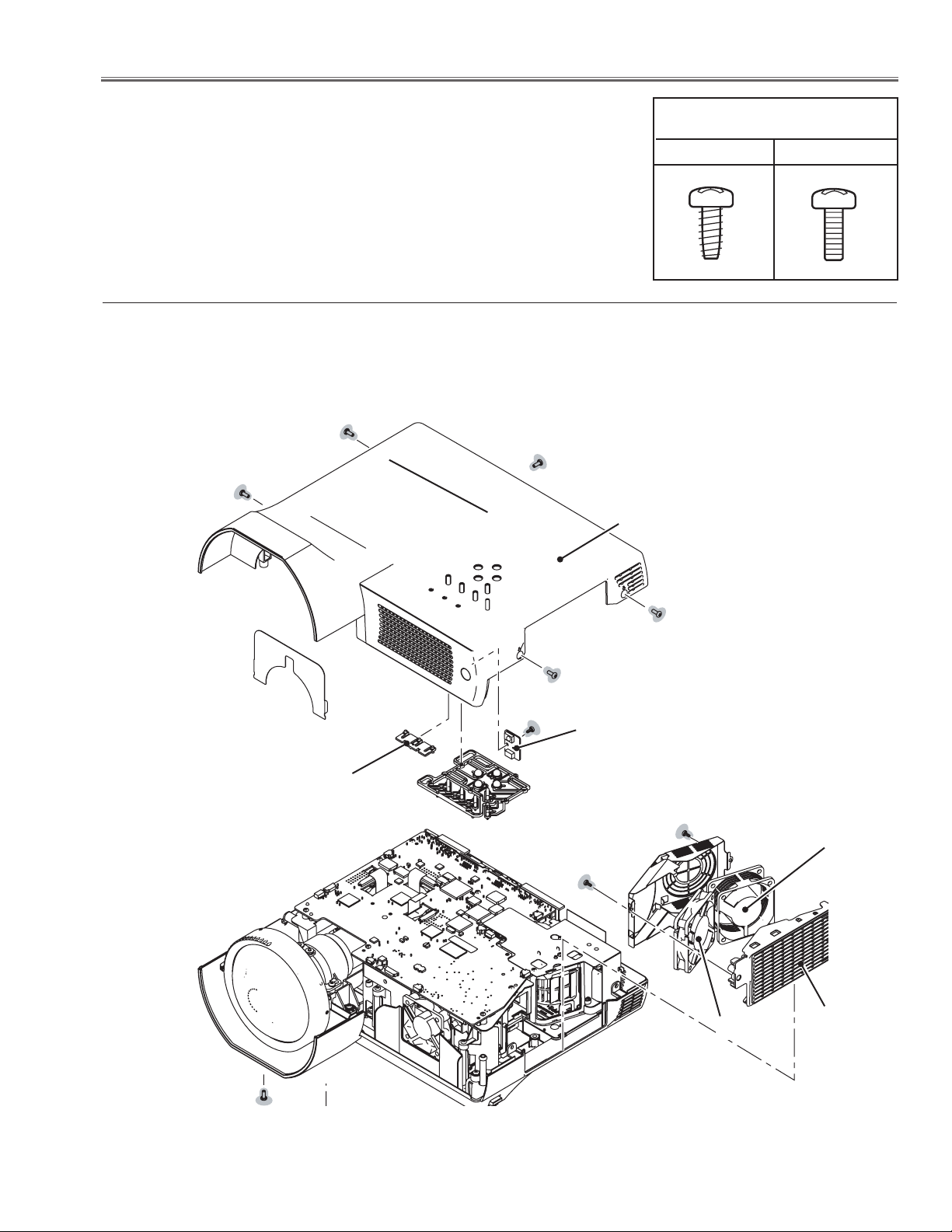
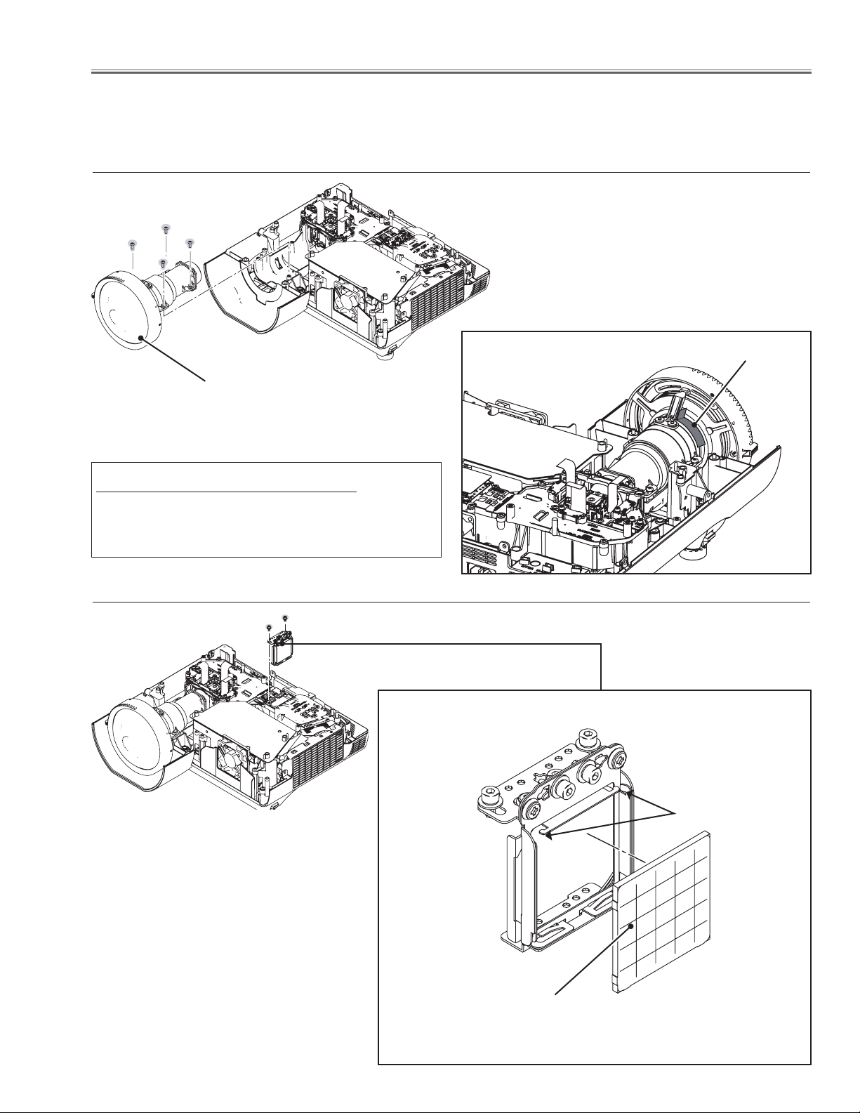
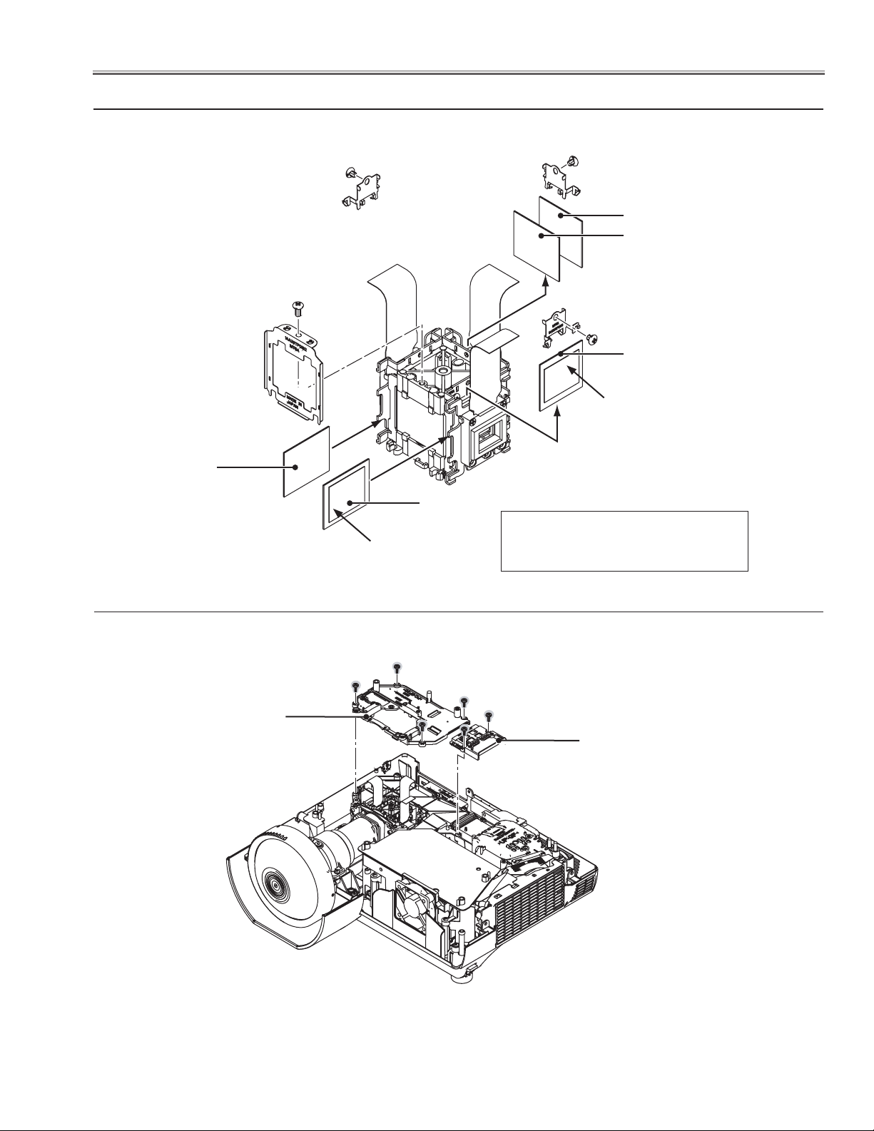
z Cabinet Top & Fans (FN901, FN902), R/C Board removal
(M3x8)x5
Cabinet top
Screws Expression
(Type Diameter x Length) mm
T type M Type
LED spacer
(M3x8)x2
(T3x6)
(T3x6)
R/C board
(T3x6)
FN902
FN901
Side grille
Fig.1
-9-
Page 10
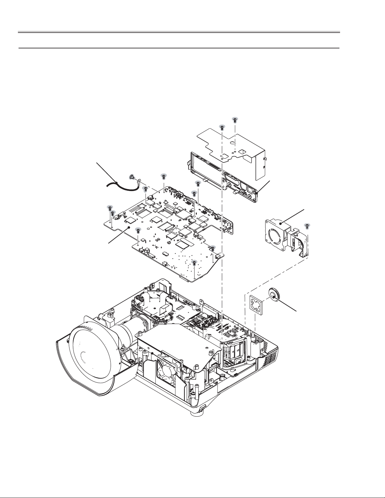
Mechanical Disassembly
x Main Board, Rear Panel, Fan(FN905), SP901 removal
Grounding
lead
(M4x5)
(M2.5x6)x8
(M2.5x6)x2
Rear panel
FN905
Main board
(T3x8)
SP901
-10-
Fig.2
Page 11
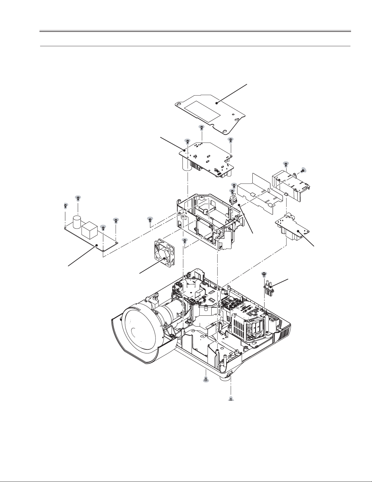
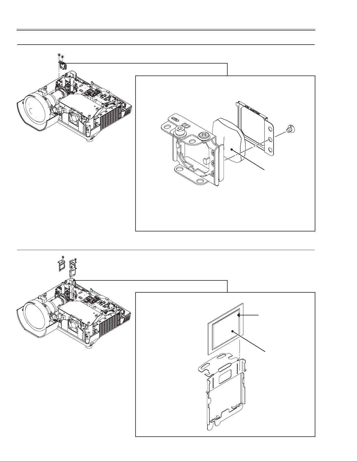
Mechanical Disassembly
c Power, Line Filte, Ballast Board, Thermal Sw(SW902), Fan(FN906) removal
Isolation sheet
Power board
(T3x6)x4
(T3x6)
(T3x6)
(T3x6)x4
Ballast board
FN906
FN906
(T3x6)
(T3x6)
(T3x6)x2
Thermal switch
(SW902)
Line Filter board
(M3x8)
Ballast socket
(T3x6)(Black)
-11-
(T3x6)(Black)
Fig.3
Page 12
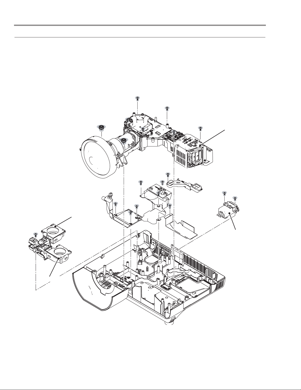
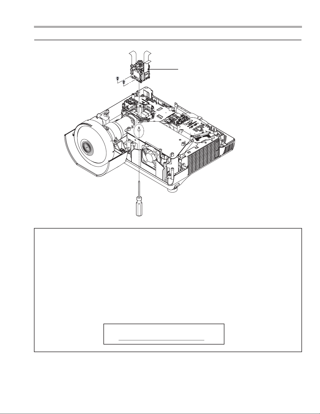
Mechanical Disassembly
v Optical Unit, Fans(FN903, FN904), Noise Filter removal
(T3x8)x6
(T3x12)x2
Optical unit
(T3x8)
(T3x6)
(T3x10)x4
(T3x6)x2
(T3x6)x3
FN904
Noise filter
FN903
-12-
Fig.4
Page 13
Optical Parts Disassembly
Before taking this procedure, remove Cabinet Top , Cabinet Front and Main Board following to the “Mechanical
Disassembly”.
Disassembly requires a 2.0mm hex wrench.
z Projection lens removal
(M3x8)x4
Fixing tape
Projection lens
Fig.1
Note on replaceing the Projection Lens
- When the Projection Lens is replaced with the new
one, make sure that the fixing tape must be removed
as the figuer.
x Integrator lens-in disassembly
(M2.5x5)x2
Integrator Lens-In Ass'y
Hooks
Fig.2
Integrator lens-in
* Rugged surface
(Behind)
-13-
Page 14
Optical Pats Disassembly
c Relay lens disassembly
(M2.5x5)x2
Relay lens Ass'y
(M2x3)
Relay lens
Fig.3
v Polarized glass-in disassembly
(M2.5x5)x1
Polarized glass-in Ass'y
Film side
Polarized glass
Fig.4
-14-
Page 15
Optical Parts Disassembly
b LCD Panel/Prism Ass’y removal
(M2.5x4)x2
(M3x10)
(Bottom side)
LCD Panel/
Prism Ass’y
Fig.5
IMPORTANT NOTICE on LCD Panel/Prism Ass'y Replacement
LCD panels used for this model can not be replaced separately. Do not disassemble the LCD Panel/Prism Ass’y.
These LCD panels are installed with precision at the factory. When replacing the LCD panel, should be replaced
whole of the LCD panels and prism ass’y at once.
After replacing LCD Panel/Prism ass’y, please check the following points.
- Check that there is no color shading at the top, bottom, left or right of the screen. If there is, try to remove the
shading following to the chapter “Optical Adjustment”.
- Check the white balance. If it needs the adjustment, adjust the white balance following to the “White Balance
Adjustment” , “Gamma Adjustment” and “Common Centre Adjustment” in the chapter “Electrical Adjustment”.
- Check the white uniformity on the screen.
If you find the color shading at the some part of the screen, it needs to take the color shading adjustment. This
adjustment should be performed by a computer and it also requires a special software “Color Shading Correction”.
The software will be supplied separately and can be ordered as follows;
COLOR SHADING CORRECTION Ver. 4.00
Service Parts No. 645 075 9611
-15-
Page 16
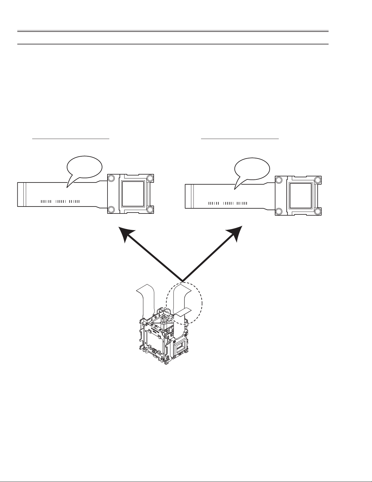
Panel Type Check
L3P06X-65G00
1-B-1234A1
-65G00
L3P06X-66G000
1-B-1234A1
-66G00
There are 2 types of LCD/Prism Ass'y for this model. Either L-Type or R-Type LCD /Prism Ass'y is used on the projector. Check which type of LCD/Prism Ass'y is used with the figure below.
When replacing the LCD/Prism Ass'y, you need to take "Panel Type Check and Setting" on the Electrical Adjustment
for the replaced LCD/Prism Ass'y.
The gamma-characteristics is different between L-Type and R-Type LCD /Prism Ass'y.
How to check the type of LCD/Prism Ass'y
Check the printed number on the flat cable of the G-LCD Panel.
L-Type LCD/Prism Ass'y R-Type LCD/Prism Ass'y
G-LCD PANEL
-16-
Page 17
Optical Parts Disassembly
n Polarized glass, Pre-polarized glass removal
Polarized Glass(R)
(Red)
(M2x4)
(M2x2)
Film
(Green)
Polarized
Glass(B)
(M2x2)
Pre-Polarized Glass(G)
Polarized Glass(G)
(M2x2)
Pre-Polarized Glass(B)
Film
(Blue)
Fig.6
* Mount the polarized glasses as the
film attached side comes to the LCD
panel side.
m Optical Unit Top removal
Optical top cover
(M3x8)x4
(M3x8)x2
Optical top cover-A
Fig.7
-17-
Page 18
Optical Parts Disassembly
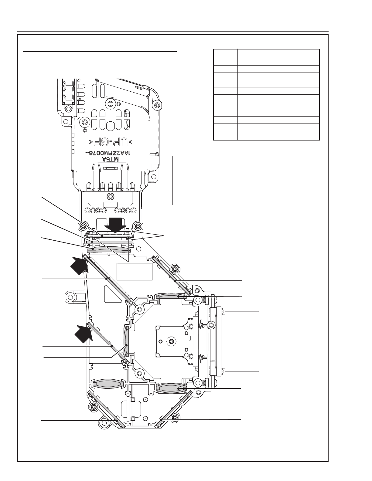
, Locations and Directions
When mounting or assembling the optical parts in the
optical unit, the parts must be mounted in the specified
location and direction as shown in figure below.
1
No. Parts Name
1 Integrator lens (OUT)
2 Prism beam splitter (PBS)
3 Condenser lens (OUT)
4 Dichroic mirror (B)
5 Dichroic mirror (G)
6 Condenser lens (G)
7 Mirror (R)
8 Condenser lens (R)
9 Condenser lens (B)
10 Mirror (B)
The arrows in the figure indicate the mount direction
of the part for the replacement. Check the number on
the arrows and mount each part according to its note;
A: The printed part no. comes to this side.
B: Rugged surface comes to this side.
2
B
3
A
4
Place the lens
as the leddes
come up side.
slit
10
9
A
5
6
8
7
7
Fig.8
-18-
Page 19
Adjustments
Adjustments after Parts Replacement
● : Adjustment necessary ❍ : Check necessary
Disassembly / Replaced Parts
LCD/
Prism Ass’y
Co ntrast A dj ustment
R- Contrast a djustment ●
G- Contrast a djustment ●
B- Contrast a djustment ●
In tegrato r lens ad ju st ment ❍ ●
Optical Adjustments
Re lay lens-out adjustment ❍ ●
Pane l type check and se tt in g ● ●
Fan co nt ro l adjustment ● ●
Ped estal ad ju st me nt [ PC ] ●
Integrator
Lens (OUT)
Relay
Lens (OUT)
Polarized glass
R G B
Power
Board
Main Board
Ga in a dj us tm en t [PC]
Ped estal ad ju st me nt [ 10 80 i] ●
Ga in a dj us tm en t [108 0i ] ●
Ga in a dj us tm en t [Vid eo ] ●
Co mmon c en te r adjust me nt ● ●
50% w hi te adjustment [PC] ● ●
Wh ite ba la nc e adjust me nt [PC] ❍ ❍
Electrical Adjustments
50% w hi te adjustment [Video] ● ●
Wh ite ba la nc e adjust me nt [Video] ❍ ❍
Wh ite un ifor mi ty a dj us tm en t ❍ ❍
●
-19-
Page 20
Optical Adjustments
Before taking optical adjustments below, remove the Cabinet Top following to the “Mechanical Disassembly”.
Adjustments require a 2.0mm hex wrench and a slot screwdriver. When you adjust Integrator lens or Relay lens
adjustment, you need to disconnect FPC cables of LCD panels on the main board.
Optical adjustment requires a 2.0mm hex wrench and a slot screwdriver.
Note: Do not disconnect connectors on the main board, because the projector cannot turn on due to operate the
power failure protection.
WARNING : USE UV RADIATION EYE AND SKIN
PROTECTION DURING SERVICING
CAUTION: To prevent suffer of UV radiation, those adjustment
must be completed within 25 minutes.
A
Contrast adjustment
[Before Adjustment]
- Input a 100% of black raster signal.
1 Loosen a screw A (Fig.1-1/1-2) on the polarized glass mounting
base which you intend to adjust.
2 Turn the polarized glass mounting base as shown in Fig.1-1 to
obtain the darkest brightness on the screen.
3 Tighten the screw A to fix the polarized glass mounting base.
Polarized glass
mounting base
Repeat steps 1 to 3 for remaining polarized glasses.
Main Board
Fig.1-1
R-Polarized Glass
Mounting Base
A
A
B-Polarized Glass
Mounting Base
-20-
G-Polarized Glass
Mounting Base
A
Fig.1-2
Page 21
Optical Adjustments
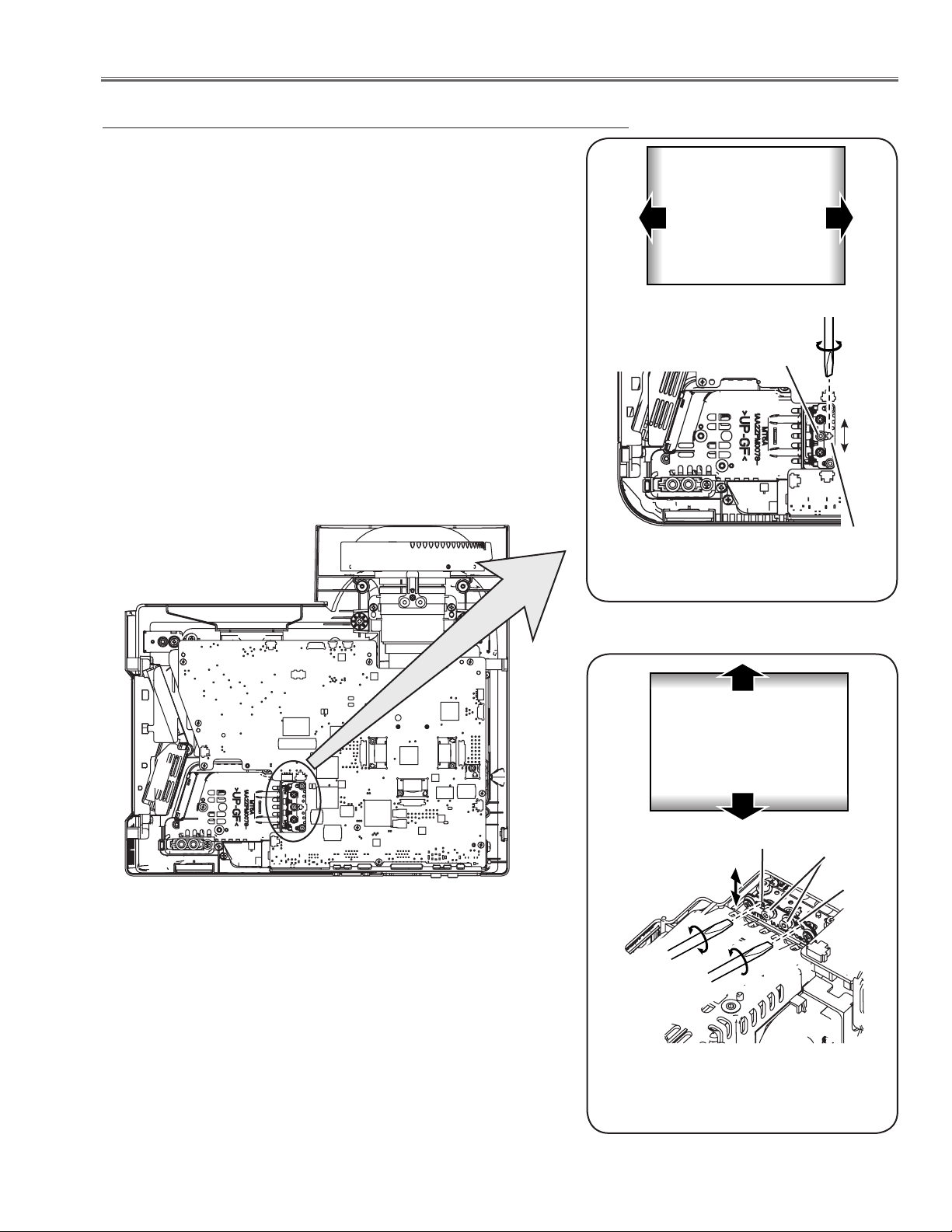
Integrator lens adjustment
1 Turn the projector on by a state of without FPC cables.
2 Project all of lights on the screen.
3 Adjust the adjustment base of integrator lens assy to make color
uniformity in white.
1) If the shading appears on the left or right of the screen as
shown in Fig.2-1, loosen 1 screw A , and adjust the slot B to
make color uniformity in white by using a slot screwdriver.
2) If the shading appears on the top or bottom of the screen as
shown in Fig.2-2, loosen 2 screws C, and adjust the slots D to
make color uniformity in white by using a slot screwdriver
4 Tighten screws A and C to fix the Integrator lens unit.
Note:
The relay lens adjustment must be carried out after completing this
adjustment.
a
White
b
A
A
a
b
Fig.2-1
Moving of slot B
White
x
y
Slot D
Slot B
C
Slot D
-21-
Fig.2-2
Moving of Slot D
Page 22
Optical Adjustments
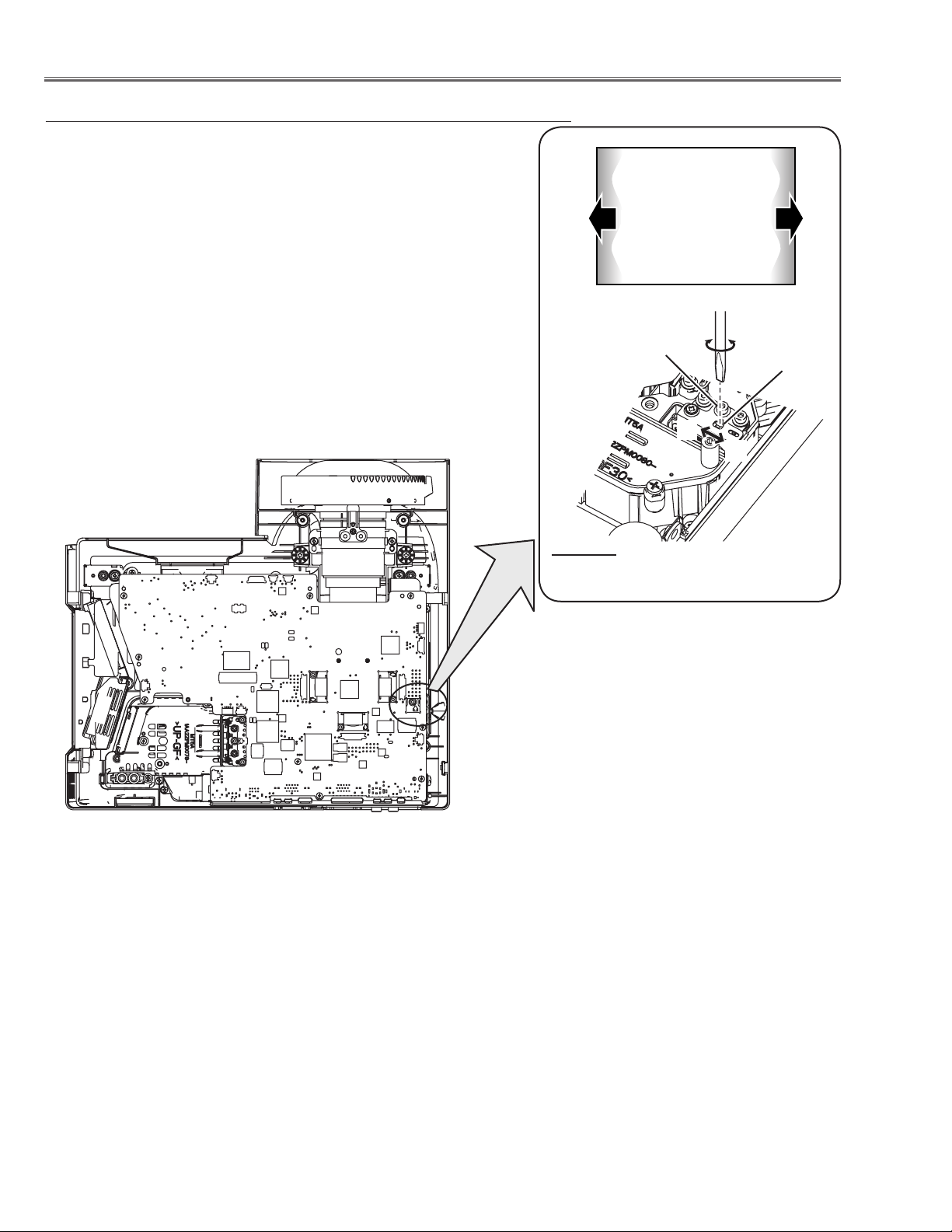
Relay lens-Out adjustment
1 Turn the projector on by a state of without FPC cables.
2 Project all of lights on the screen.
3 Adjust the adjustment base of relay lens assy to make color unifor-
mity in white.
If the shading appears on the left or right of the screen as shown
in Fig.3, loosen 1 screw A, and adjust the slot B to make color
uniformity in white by using a slot screwdriver.
4 Tighten the screws A to fix the relay lens unit.
b
White
a
A
Fig.3
Moving of slot B
Slot B
a
b
-22-
Page 23
Service Mode
Input Video
Group No. Data
0 0 32
Ver. 1 .00
Electrical Adjustments
ON
OFF
POWER
KEYSTONE
INPUT
WARNING
LAMP REPLACE
MENU
VO
LUME
+ VO
L
UME
SELECT
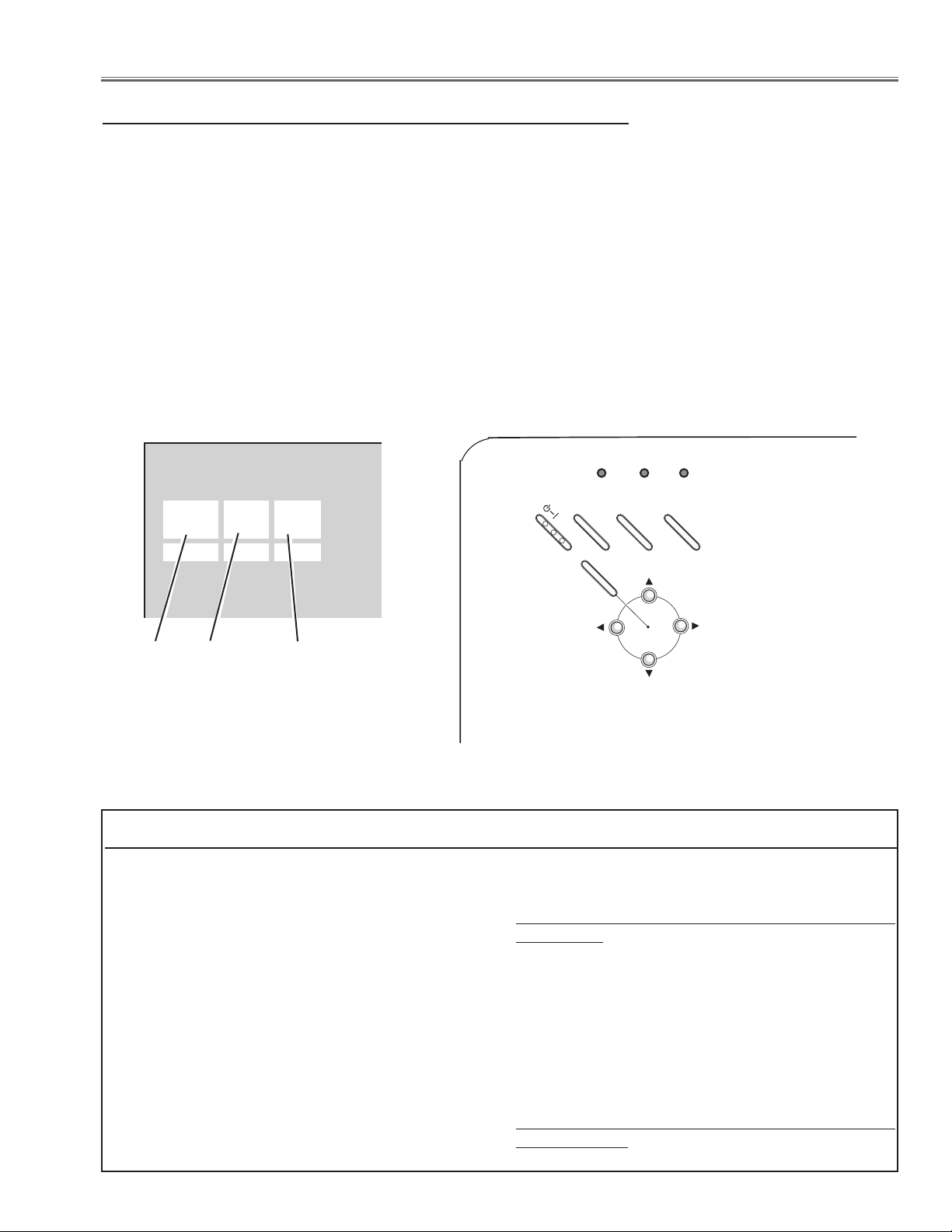
Service Adjustment Menu Operation
To enter the service mode
To enter the “Service Mode”, press and hold the MENU and INPUT buttons on the projector at the same time for
more than 3 seconds. The service menu appears on the screen as follows.
To adjust service data
Select the adjustment group no. by pressing the MENU (+) or KEYSTONE (-) button, and select the adjustment
item no. by pressing the pointer e or d button, and change the data value by pressing the 7 or 8 button. Refer
to the “Service Adjustment Data Table” for further description of adjustment group no., item no. and data value.
To exit the service mode
To exit the service mode, press the POWER ON-OFF button on the projector or remote control unit.
Group No.
Item No.
Data value
Memory IC (IC1371) Replacement
Memory IC on the main board stores the data for
the service adjustments, and should not be replaced
except for the case of defective device.
If replaced, the re-adjustments are required following
to the “Electrical Adjustments”.
The data of lamp replacement counter is stored in the
Memory IC.
Please note that the lamp replace counter will be
reset when the memory IC is replaced.
(Lamp replace counter cannot be set to the previous
value.)
● Caution to memory IC replacement
When memory IC is replaced with new one, the CPU
writes down the default data of the service adjustments to the replaced IC as the mentioned on the service adjustment table. As these data are not the same
data as factory shipped data, it should be required to
perform the re-adjustments following to the “Electrical
Adjustments”.
Please note that in this case the lamp replace counter
will be reset.
●
Caution of Main Board replacement (in the case
memory IC is not defective)
When the main board is replaced, memory IC should
be replaced with the one on previous main board.
After replacement, it should be required to perform the re-adjustments following to the “Electrical
Adjustments”.
In this case, the lamp replace counter can be kept the
value as before.
-23-
Page 24
White 100%
Black 100%
Electrical Adjustments
Circuit Adjustments
CAUTION: The each circuit has been made by the fine adjustment at factory. Do not attempt to adjust the follow-
ing adjustments except requiring the readjustments in servicing otherwise it may cause loss of performance and product safety.
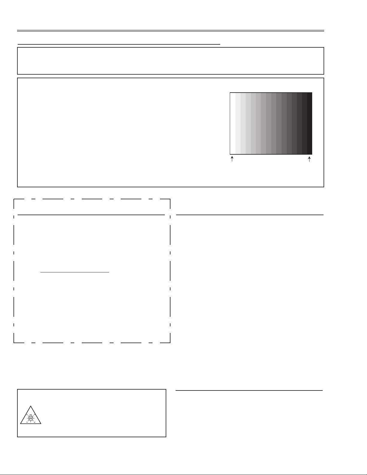
[Adjustment Condition]
● Input signal
Video signal ......................... 1.0Vp-p/75
scale (Composite video signal)
Computer signal .................... 0.7Vp-p/75W terminated, 16 steps gray
scale pattern
Component Video signal....... 0.7Vp-p/75W terminated, 16 steps gray
scale (Component video signal with
480p, 575p, 720p or 1080i format)
● Picture control mode............... “STANDARD” mode unless otherwise
noted.
Note:
* Please refer to “Service Adjustment Menu Operation” for entering the service mode and adjusting the service
data.
Output Voltage adjustment
After replacing the Power Board readjust the Output
voltage adjustment as follows.
1. Connect a digital voltmeter to pins 1 (+) and 3 (-) of
K6D.
2. Adjust the voltage by using VR611 as following.
AC Input Reading
230V 380V ±2V
Caution:
Be sure to connect the lamp when taking this adjustment.
* This adjustment is not required even if the power
board is replaced because this adjustment is carried
out before parts shipment.
W terminated, 16 steps gray
z Panel Type Check and Setting
1. Enter the service mode.
2. Panel Type Check
Select group no. “
value as follows;
Data value: 0 For L-Type of LCD Panel
Data value: 20 For R-Type of LCD panel
3. Panel Type Setting
Select group no. “
value from 10 to 0 or 20 depending on your LCD
Panel type. When the data value reaches 0 or 20,
it returns to 10 quickly. The gamma-characteristics
changes according to your selection.
* Refer to the item "LCD Panel/Prism Ass'y removal"
for the panel type check.
Note:
Be careful to take this adjustment. The value of gamma
adjustment data will be reset and cannot be restored if
you change the mode of LCD panel type.
16 steps gray scale pattern
290”, item no. “0”. Check the data
290”, item no. “1” and change data
WARNING : USE UV RADIATION EYE
AND SKIN PROTECTION
DURING SERVICING
x Fan Control adjustment
1. Enter the service mode.
2. Connect a digital voltmeter to test point “
(+) and chassis ground (-). Select group no. “111”,
item no. “94” and change data value to adjust voltage to be 5.2 ±0.1V.
3. Connect a digital voltmeter to test point “TPFANB”
(+) and chassis ground (-). Select item no. “96” and
change data value to adjust voltage to be 6.3 ±0.1V.
-24-
TPFANA”
Page 25
Electrical Adjustments
Pedestal Lebel
Black Lebel
Pedestal Lebel
Black Lebel
(a)
White Level
(a)
White Level
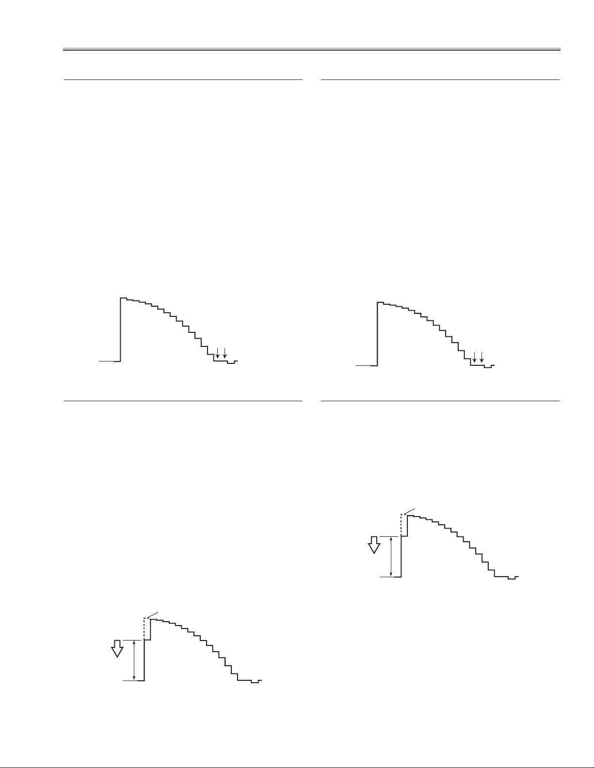
c Pedestal adjustment [PC]
1. Receive the 16-step grey scale computer signal with
Computer1 [RGB] mode.
2. Enter the service mode.
3. Connect an oscilloscope to test point “TP_G1” (+)
and chassis ground (-).
4. Select group no. “0”, item no. “0” and change data
value to adjust the pedestal level and black level to
be the same level.
5. Connect an oscilloscope to test point “TP_R1” (+)
and chassis ground (-).
6. Select item no. “1” and change data value to adjust
the pedestal level and black level to be the same
level.
7. Connect an oscilloscope to test point “TP_B1” (+)
and chassis ground (-).
8. Select item no. “2” and change data value to adjust
the pedestal level and black level to be the same
level.
b Pedestal adjustment [1080i]
1. Receive the 16-step grey scale component signal
with Computer1 [Component1080i] mode.
2. Enter the service mode.
3. Connect an oscilloscope to test point “TP_G1” (+)
and chassis ground (-).
4. Select group no. “0”, item no. “0” and change data
value to adjust the pedestal level and black level to
be the same level.
5. Connect an oscilloscope to test point “TP_R1” (+)
and chassis ground (-).
6. Select group no. “0”, item no. “1” and change data
value to adjust the pedestal level and black level to
be the same level.
7. Connect an oscilloscope to test point “TP_B1” (+)
and chassis ground (-).
8. Select group no. “0”, item no. “2” and change data
value to adjust the pedestal level and black level to
be the same level.
v Gain adjustment [PC]
1. Receive the 16-step grey scale computer signal with
Computer1 [RGB] mode.
2. Enter the service mode.
3. Connect an oscilloscope to test point “TP_G1” (+)
and chassis ground (-).
4. Select group no. “0”, item no. “3” and adjust the
amplitude “a” to be minimum by changing the Data
value.
5. Connect an oscilloscope to test point “TP_R1” (+)
and chassis ground (-).
6. Select item no. “4” and adjust the amplitude “a” to be
minimum by changing the Data value.
7. Connect an oscilloscope to test point “TP_B1” (+)
and chassis ground (-).
8. Select item no. “5” and adjust the amplitude “a” to be
minimum by changing the Data value.
n Gain adjustment [1080i]
1. Receive the 16-step grey scale component signal
with Computer1 [Component1080i] mode.
2. Enter the service mode.
3. Connect an oscilloscope to test point “TP_G1” (+)
and chassis ground (-).
4. Select group no. “103”, item no. “0” and adjust the
amplitude “a” to be minimum by changing the Data
value.
-25-
Page 26
Electrical Adjustments
(a)
white level
white level
(a)
White Level
(a)
white level
white level
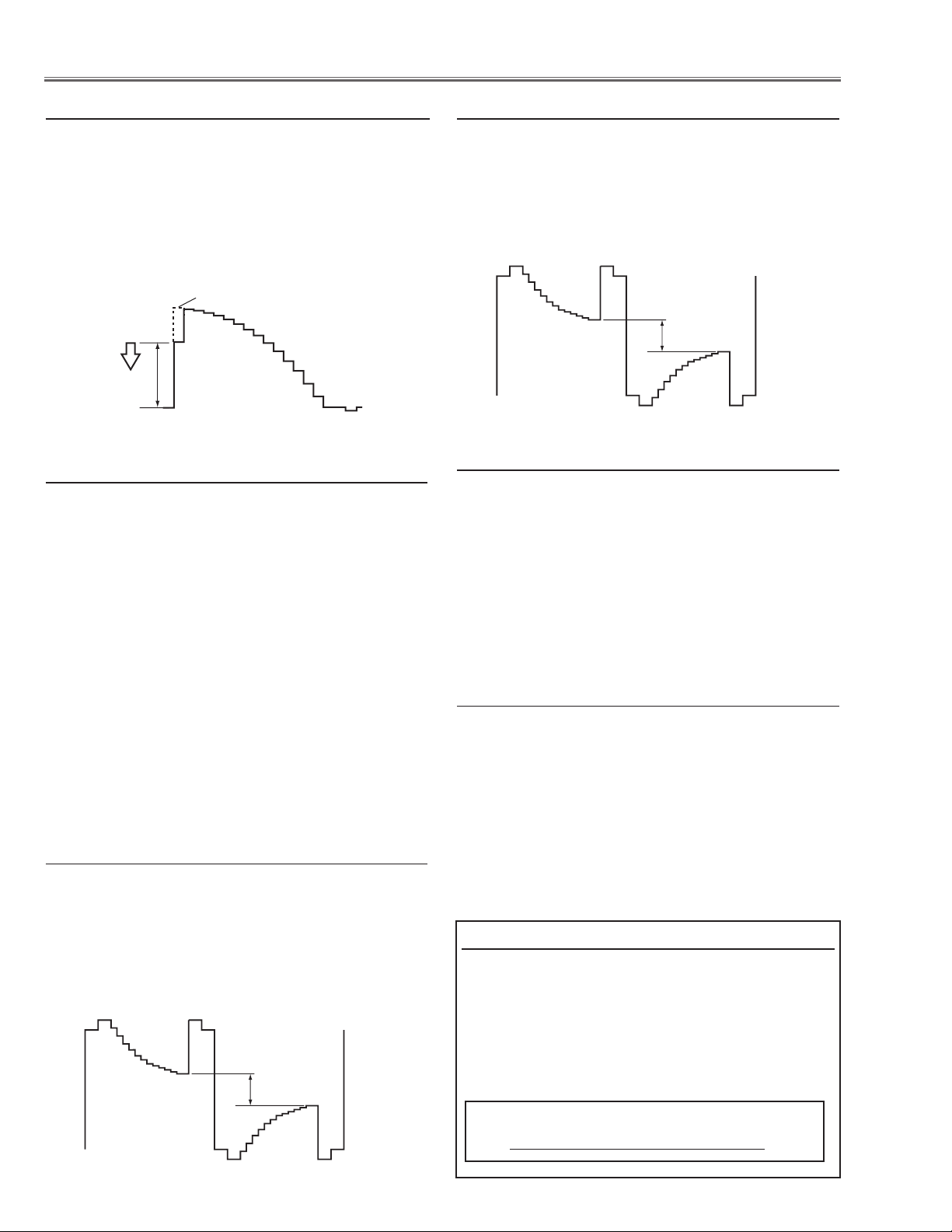
m Gain adjustment [Video]
1. Receive the 16-step grey scale composite signal with
Video [Video] mode.
2. Enter the service mode.
3. Connect an oscilloscope to test point “TP_G1” (+)
and chassis ground (-).
4. Select group no. “103”, item no. “0” and adjust the
amplitude “a” to be minimum by changing the Data
value.
, Common Center adjustment
1. Receive the 50%-Whole Gray computer signal with
Computer1 [RGB] mode.
2. Enter the service mode.
3. Select group no. “9”, item no. “92” and change data
value to “2” to reduce the panel frequency.
4. Project only green light component to the screen.
5. Select group no. “10”, item no. “1” and change data
value to obtain the minimum flicker on the screen.
6. Project only red light component to the screen.
7. Select item no. “0” and change data value to obtain
the minimum flicker on the screen.
8. Project only blue light component to the screen.
9. Select item no. “2 and change data value to obtain
the minimum flicker on the screen.
10. Select group no. “9”, item no. “92” and change
data value to “0” to reset the panel frequency.
⁄0 50% White adjustment [Video]
1. Receive the 16-step grey scale composite video signal with Video [Video] mode.
2. Enter the service mode.
3. Connect an oscilloscope to test point “TP_G1” (+)
and chassis ground (-).
4. Select group no. “9”, item no. “7” and change data
value to adjust amplitude “a” to be 1.6 ±0.1V.
⁄1 White Balance adjustment [PC]
1. Receive the 16-step gray scale computer signal with
Computer1 [RGB] mode.
2. Enter the service mode, select group no. “
9” item
no. “6” (Red) or “8” (Blue), and change Data values
respectively to make a proper white balance.
Confirm that the same white balance is obtained in
video and computer input.
⁄2 White Balance adjustment [Video]
1. Receive the 16-step grey scale composite video signal with Video [Video] mode.
2. Enter the service mode, select group no. “
no. “6” (Red) or “8” (Blue), and change Data values
respectively to make a proper white balance.
9” item
. 50% White adjustment [PC]
1. Receive the 16-step grey scale computer signal with
Computer1 [RGB] mode.
2. Enter the service mode.
3. Connect an oscilloscope to test point “TP_G1” (+)
and chassis ground (-).
4. Select group no. “9”, item no. “7” and change data
value to adjust amplitude “a” to be 1.6 ±0.1V.
Confirm that the same white balance is obtained in
video and computer input.
Note On White Uniformity Adjustment
If you find the color shading on the screen, please
adjust the white uniformity by using the proper
computer and “Color Shading Correction” software
supplied separately.
The software can be ordered as follows;
COLOR SHADING CORRECTION Ver. 4.00
Service Parts No. 645 075 9611
-26-
Page 27
)#
+"
+'
40?"
+2
++
+,
+-
+$
+%
+(
+,
+.
+0
+3
+:
40?'
)#
)#
40?2
)#
40&!.!
40&!."
)#
)#
)#
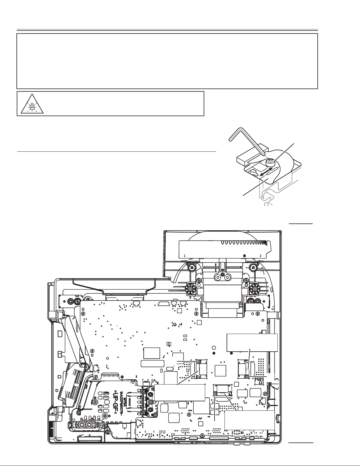
Electrical Adjustments
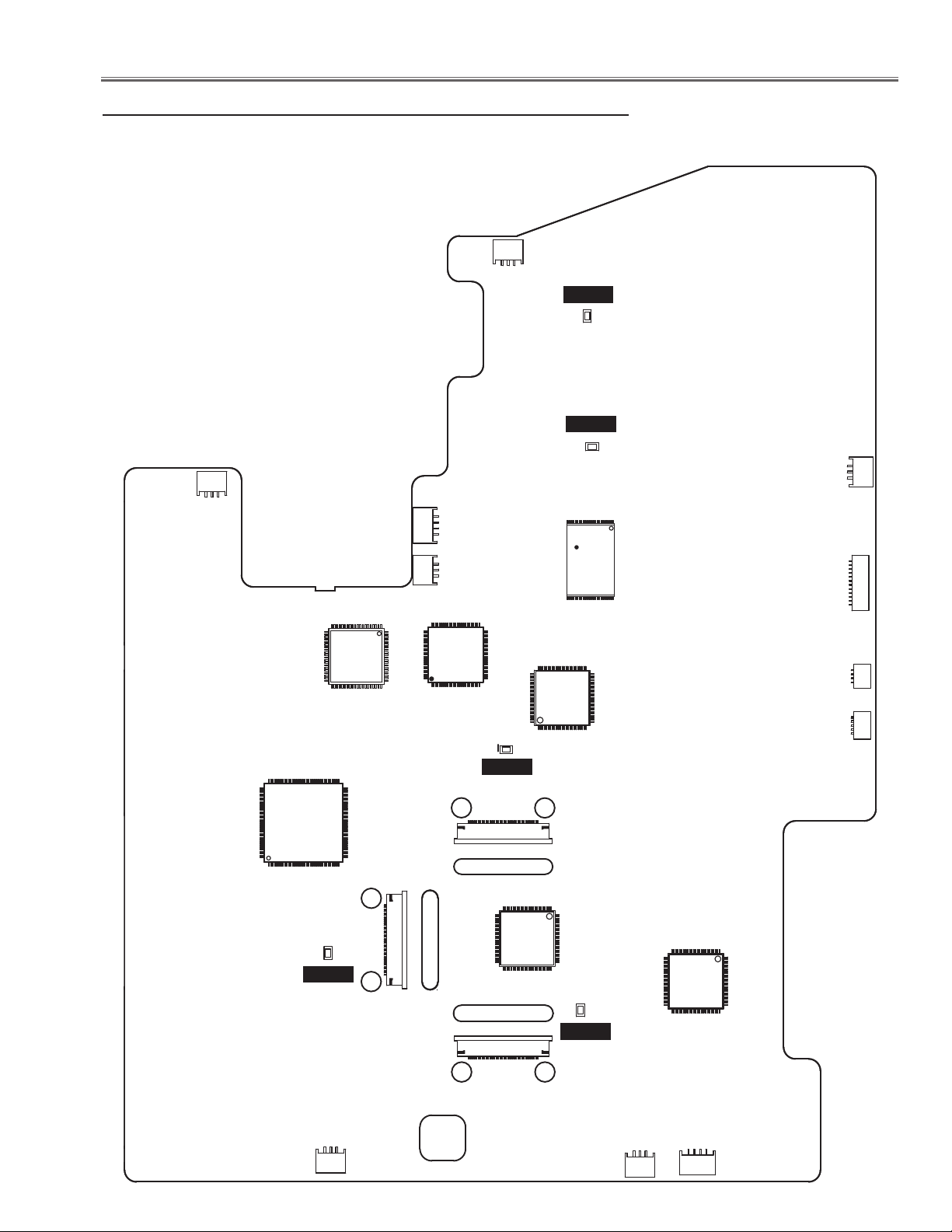
Test Points and Locations
MAIN BOARD
-27-
Page 28
Electrical Adjustments
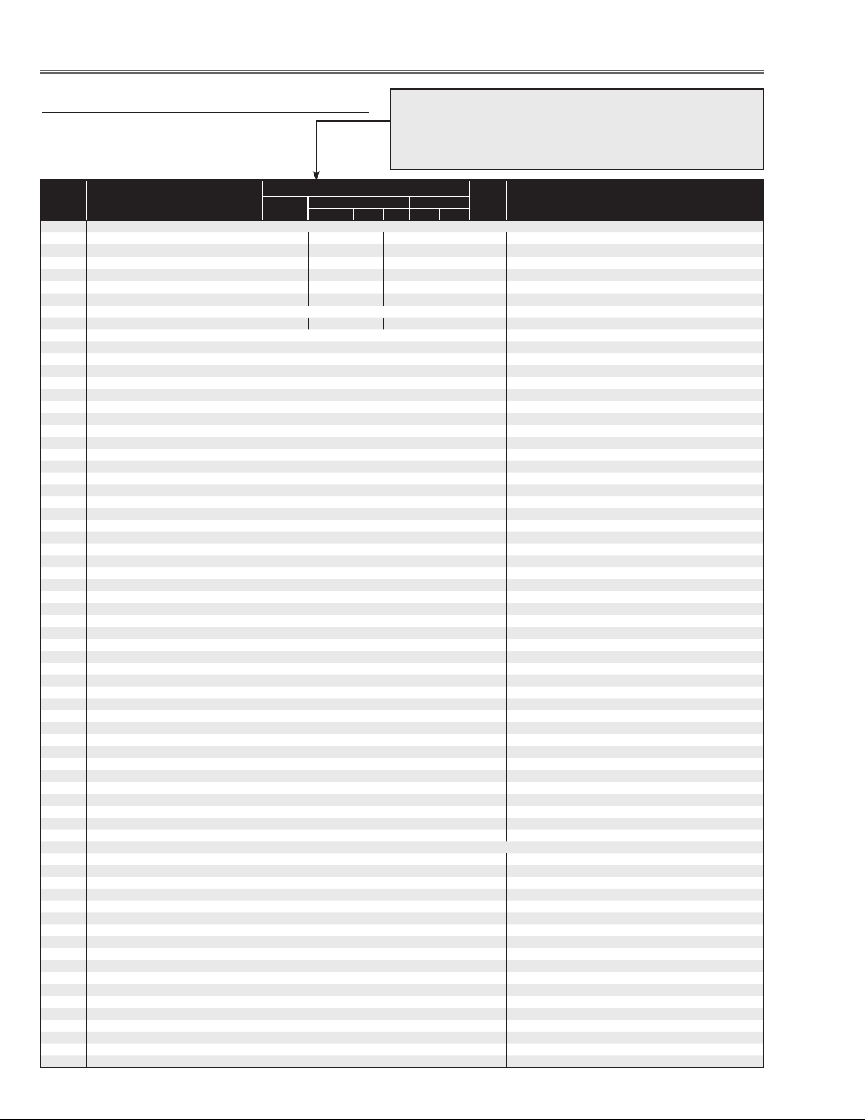
Service Adjustment Data Table
These initial values are the reference data written from the
CPU ROM to memory IC when replaced new memory IC. The
adjustment items indicated with “✻” are required to readjust following to the “Electrical adjustments”. Other items should be
used with the initial data value.
Item No. NAME Device
Group 0 AD9883
0 ADC G-OFFSET AD9883 55 55
1 ADC R-OFFSET AD9883 55 55
2 ADC B-OFFSET AD9883 55 55
3 ADC G-GAIN AD9883 70 128
4 ADC R-GAIN AD9883 70 128
5 ADC B-GAIN AD9883 70 128
6
10 VCO 0 Thresh MAX AD9883 32 32 32 Maximum frequency to select VCO 0
11 VCO 1 Thresh MAX AD9883 58 Maximum frequency to select VCO 1
12 VCO 2 Thresh MAX AD9883 110 Maximum frequency to select VCO 2
13
20 CPC 0 Thresh MAX (VCO 0) AD9883 0 Maximum frequency to select CPC0 at VCO 0
21 CPC 1 Thresh MAX (VCO 0) AD9883 0 Maximum frequency to select CPC1 at VCO 0
22 CPC 2 Thresh MAX (VCO 0) AD9883 15 Maximum frequency to select CPC2 at VCO 0
23 CPC 3 Thresh MAX (VCO 0) AD9883 18 Maximum frequency to select CPC3 at VCO 0
24 CPC 4 Thresh MAX (VCO 0) AD9883 23 Maximum frequency to select CPC4 at VCO 0
25 CPC 5 Thresh MAX (VCO 0) AD9883 32 Maximum frequency to select CPC5 at VCO 0
26 CPC 6 Thresh MAX (VCO 0) AD9883 255 Maximum frequency to select CPC6 at VCO 0
27
30 CPC 0 Thresh MAX (VCO 1) AD9883 0 Maximum frequency to select CPC0 at VCO 1
31 CPC 1 Thresh MAX (VCO 1) AD9883 0 Maximum frequency to select CPC1 at VCO 1
32 CPC 2 Thresh MAX (VCO 1) AD9883 0 Maximum frequency to select CPC2 at VCO 1
33 CPC 3 Thresh MAX (VCO 1) AD9883 0 Maximum frequency to select CPC3 at VCO 1
34 CPC 4 Thresh MAX (VCO 1) AD9883 0 Maximum frequency to select CPC4 at VCO 1
35 CPC 5 Thresh MAX (VCO 1) AD9883 48 Maximum frequency to select CPC5 at VCO 1
36 CPC 6 Thresh MAX (VCO 1) AD9883 65 Maximum frequency to select CPC6 at VCO 1
37
40 CPC 0 Thresh MAX (VCO 2) AD9883 0 Maximum frequency to select CPC0 at VCO 2
41 CPC 1 Thresh MAX (VCO 2) AD9883 0 Maximum frequency to select CPC1 at VCO 2
42 CPC 2 Thresh MAX (VCO 2) AD9883 0 Maximum frequency to select CPC2 at VCO 2
43 CPC 3 Thresh MAX (VCO 2) AD9883 0 Maximum frequency to select CPC3 at VCO 2
44 CPC 4 Thresh MAX (VCO 2) AD9883 0 Maximum frequency to select CPC4 at VCO 2
45 CPC 5 Thresh MAX (VCO 2) AD9883 75 Maximum frequency to select CPC5 at VCO 2
46 CPC 6 Thresh MAX (VCO 2) AD9883 95 Maximum frequency to select CPC6 at VCO 2
47
50 CPC 0 Thresh MAX (VCO 3) AD9883 0 Maximum frequency to select CPC0 at VCO 3
51 CPC 1 Thresh MAX (VCO 3) AD9883 0 Maximum frequency to select CPC1 at VCO 3
52 CPC 2 Thresh MAX (VCO 3) AD9883 0 Maximum frequency to select CPC2 at VCO 3
53 CPC 3 Thresh MAX (VCO 3) AD9883 0 Maximum frequency to select CPC3 at VCO 3
54 CPC 4 Thresh MAX (VCO 3) AD9883 0 Maximum frequency to select CPC4 at VCO 3
55 CPC 5 Thresh MAX (VCO 3) AD9883 0 Maximum frequency to select CPC5 at VCO 3
56 CPC 6 Thresh MAX (VCO 3) AD9883 140 Maximum frequency to select CPC6 at VCO 3
57
60 PRECOAST (PC) AD9883 3
61 POSTCOAST(PC) AD9883 3
62 PRECOAST (PC Video) AD9883 10
63 POSTCOAST(PC Video) AD9883 4
64 PRECOAST (Component) AD9883 10 Maximum frequency to select CPC6 at VCO 3
65 POSTCOAST(Component) AD9883 4 Maximum frequency to select CPC7 at VCO 3
70 FREQ OFFSET AD9882 0 Offset at DCLK more than 82MHz for AD9882
Group 1
UPD64012
7 IMODE uPD64012 0
8 RGB_MIX uPD64012 2
9 AUTOCLR uPD64012 1
10 SIGDETLV uPD64012 1
11 SIGON uPD64012 1
12 SIGOFF uPD64012 0
13 TV50F uPD64012 0
14 TV60F uPD64012 0
15 SETINT uPD64012 1
16 SETPRG uPD64012 0
17 COLORM uPD64012 0
18 KILOFFT uPD64012 0
19 UNLINC uPD64012 0
20 DETOUT uPD64012 3
21 DETTIM uPD64012 3
22 CLKVA uPD64012 1
23 CLKKLL uPD64012 40
24 CODDEN uPD64012 0
PC
XGA
Component Video
HDTV 480p 480i NTSC PAL
Range Description
PC/AV 30KHz/AV 15KHz
PC/AV 30KHz/AV 15KHz
PC/AV 30KHz/AV 15KHz
PC/AV 30KHz/AV 15KHz
PC/AV 30KHz/AV 15KHz
PC/AV 30KHz/AV 15KHz
✻ Pedestal Adj.(PC),(1080i)
✻ Pedestal Adj.(PC),(1080i)
✻ Pedestal Adj.(PC),(1080i)
✻ Gain Adj.(PC),(1080i)
✻ Gain Adj.(PC),(1080i)
✻ Gain Adj.(PC),(1080i)
-28-
Page 29
Electrical Adjustments
Item No. NAME Device
25 CRDLY uPD64012 1
26 PHBDL uPD64012 0
27 PHRDL uPD64012 0
28 CBOFS uPD64012 0
29 CROFS uPD64012 0
30 FRCENY uPD64012 0
31 FRCENC uPD64012 0
32 DLYCTL uPD64012 8
33 OUTBITW uPD64012 0
34 CLKOINV uPD64012 1
35 RDOSEL uPD64012 0
36 SQCBCR uPD64012 0
37 ACTVH uPD64012 128
38 HPOSI uPD64012 128
39 HSPOS uPD64012 132
40 HSWID uPD64012 64
41 FSTAV uPD64012 0
42 VSPOS uPD64012 64
43 VSWID uPD64012 2
44 VBKFAL uPD64012 260
45 VBKRIS uPD64012 16
46 INBKENA uPD64012 0
47 YBLK uPD64012 0
48 SYNCSEL uPD64012 1
49 VDSEL uPD64012 1
50 HSPOL uPD64012 1
51 VSPOL uPD64012 1
52 FIELDPOL uPD64012 1
53 INHBKST uPD64012 715
54 INHBKEN uPD64012 853
55 INVBLKST uPD64012 260
56 INVBLKEN uPD64012 16
57 FLDTHR uPD64012 0
58 FILDIV uPD64012 0
59 TSRTCNV uPD64012 1
60 R_GAIN uPD64012 22 22 22 10
61 G_GAIN uPD64012 22 22 22 17
62 B_GAIN uPD64012 22 22 22 10
63 FLTSEL uPD64012 0
64 PEDIIRS2 uPD64012 0
65 SBCNT2 uPD64012 32
66 CBGAIN uPD64012 32
67 CRGAIN uPD64012 32
68 YGCAUTO uPD64012 0
69 YGCVAL uPD64012 42/45 42/45 45/45 45/45
70 YGCOFF uPD64012 0
71 YGCMVS uPD64012 0
72 YPGAINS uPD64012 2
73 YGCAVAL uPD64012 9
74 MAXIIRS uPD64012 0
75 PEDIIRS uPD64012 0
76 YGCMODE1 uPD64012 0
77 YGCMODE2 uPD64012 0
78 YGCIIRS uPD64012 1
79 YCSV uPD64012 0
80 YCOMA uPD64012 2
81 YCOMB uPD64012 2
82 YCSHY uPD64012 0
83 YCSHC uPD64012 0
84 COBPFOFF uPD64012 0
85 YCSCOF uPD64012 4
86 YCSSY uPD64012 0
87 VLTYPE uPD64012 1
88 YCSSC uPD64012 0
89 VAPONV uPD64012 0
90 VAPG uPD64012 4
91 VAPI uPD64012 16
92 PALCFIL uPD64012 0
93 YCSY2F uPD64012 3
94 TRF uPD64012 0
95 TRGAIN uPD64012 0
96 TRPAL uPD64012 0
97 APCGAIN uPD64012 1
98 ACCGAIN uPD64012 1
99 ACCLIM uPD64012 8
100 STNTSCM uPD64012 0
101 STPALD uPD64012 0
PC
VIDEO
NTSC/PAL
S-VIDEO
NTSC/PAL
XGA
Component Video
HDTV 480p 480i NTSC PAL
YCBCR
480i/575i
Range Description
SCART
480i/575i
-29-
Page 30
Electrical Adjustments
Item No. NAME Device
102 SBCNT uPD64012 109 / 111 104 / 106 108 / 108 102 / 102
103 SBCLRU uPD64012 128 128 128 141
104 SBCLRV uPD64012 128 128 128 141
105 YCONR uPD64012 0
106 CCONR uPD64012 0
107 YCORB uPD64012 0
108 YCOREN uPD64012 1
109 YCORH uPD64012 0
110 CCORB uPD64012 0
111 CCOREN uPD64012 0
112 LTIGAIN uPD64012 0
113 CTIGAIN uPD64012 0
114 LTITAP uPD64012 2
115 LTICORE uPD64012 3
116 CTITAP uPD64012 2
117 CTICORE uPD64012 3
118 SHPGAIN uPD64012 176
119 SHPCHAR uPD64012 2
120 SHPCORE uPD64012 0
121 BRIGHT uPD64012 512
122 OFRY uPD64012 32
123 COLORG uPD64012 128
124 HUE uPD64012 114
125 CONT uPD64012 128
126 APLWID uPD64012 0
127 APLCOE uPD64012 5
128 DCREGAIN uPD64012 8
129 BLENGAIN uPD64012 16
130 ABLENST uPD64012 0
131 BLEXST uPD64012 0
132 GAMGAIN uPD64012 0
133 AGAMGAIN uPD64012 0
134 GAMST uPD64012 255
135 BLENCTL uPD64012 0
136 YGACTL uPD64012 0
137 ACLSEN uPD64012 0
138 ACLST uPD64012 255
139 YVBCTL uPD64012 1
140 CRLPF uPD64012 1
141 CBLPF uPD64012 1
142 KILLV uPD64012 8
143 KILLVCTL uPD64012 9
144 VLIM uPD64012 0
145 VDCOR uPD64012 0
146 LPFTHR uPD64012 SCART: 0 COMPOSET/SVIDEO:0
147 ADCLK uPD64012 SCART: 3 COMOSITE/SVIDEO:2
Group 9 PANEL CONTROL
0 R-SubGain L3E07110 512/524/472/535/512/524/472/535 1-1023
1 G-SubGain L3E07110 512/524/472/472/512/524/472/472 1-1023
2 B-SubGain L3E07110 512/524/472/472/512/524/472/472 1-1023
3 R-SubBright L3E07110 0/0/24/16/0/0/24/16 1-1023
4 G-SubBright L3E07110 0/0/24/16/0/0/24/16 1-1023
5 B-SubBright L3E07110 0/0/24/16/0/0/24/16 1-1023
6 R-GammaShift L3E07110 0/0/0/0 1-1023
7 G-GammaShift L3E07110 0/0/0/0 1-1023
8 B-GammaShift L3E07110 0/0/0/0 1-1023
9 R_ReferH L3E07110 Normal:1000/Ceiling:1000 1-1023
10 R_ReferL L3E07110 Normal:304/Ceiling:304 1-1023
11 G_ReferH L3E07110 Normal:1000/Ceiling:1000 1-1023 When adjusting G, the value of R and B changes together
12 G_ReferL L3E07110 Normal:304/Ceiling:304 1-1023 When adjusting G, the value of R and B changes together
13 B_ReferH L3E07110 Normal:1000/Ceiling:1000 1-1023
14 B_ReferL L3E07110 Nor mal:304/Ceiling:304 1-1023
15 DXOUTR L3E07110 237 1-1023
16 DXOUTG L3E07110 237 1-1023
17 DXOUTB L3E07110 237 1-1023
18 H_Change_Pos L3E07110 3 0-256
19 SH_Base L3E07110 273 0-4095
20 NRG_Pos L3E07110 62 0-128
21 NRG_Width L3E07110 53 0-255
22 OSD_Pos L3E07110 2 0-3
23 OSD_Ptn L3E07110 0 0-7
24 GammaCtrl L3E07110 1 0-1
25 REF_GatePos L3E07110 5 0-1023
26 REF_GateDur L3E07110 204 0-1023
27 R-BasePos L3E07110 8 0-15
28 G-BasePos L3E07110 8 0-15 When adjusting G, the value of R and B changes together
PC
VIDEO S-VIDEO YCBCR SCART
NTSC / PAL NSTC / PAL 480i / 575i 480i / 575i
XGA
Component Video
HDTV 480p 480i NTSC PAL
Range Description
PCStandard/PCDynamic/PCReal/PCBlackBoard/
AVStandard/AVDnamic/AVCinema/AVBlackBoard
PC/DVI/HDCP/VIDEO ✻ White Balance Adj.(PC),(Video)
When adjusting G, the value of R and B changes together
✻ 50%-White Adj.(PC),(Video)
PC/DVI/HDCP/VIDEO ✻ White Balance Adj.(PC),(Video)
-30-
Page 31

Electrical Adjustments
Item No. NAME Device
29 B-BasePos L3E07110 8 0-15
30 RGB-Ajust L3E07110 0 0-7
31 RGB-AdjLv L3E07110 0 0-1023
32 LineR0 L3E07110 8 0-255
33 LineR1 L3E07110 4 0-255
34 LineR2 L3E07110 1 0-255
35 LineR3 L3E07110 255 0-255
36 LineR4 L3E07110 252 0-255
37 LineG0 L3E07110 8 0-255
38 LineG1 L3E07110 4 0-255
39 LineG2 L3E07110 1 0-255
40 LineG3 L3E07110 255 0-255
41 LineG4 L3E07110 252 0-255
42 LineB0 L3E07110 8 0-255
43 LineB1 L3E07110 4 0-255
44 LineB2 L3E07110 1 0-255
45 LineB3 L3E07110 255 0-255
46 LineB4 L3E07110 252 0-255
47 GhostR-Pos L3E07110 8 0-15
48 GhostG-Pos L3E07110 8 0-15 When adjusting G, the value of R and B changes together
49 GhostB-Pos L3E07110 8 0-15
50 GhostR-Cent L3E07110 0 0-2047
51 GhostR-Start L3E07110 128 0-255
52 GhostR-End L3E07110 128 0-255
53 GhostG-Cent L3E07110 0 0-2047 When adjusting G, the value of R and B changes together
54 GhostG-Start L3E07110 128 0-255
55 GhostG-End L3E07110 128 0-255
56 GhostB-Cent L3E07110 0 0-2047
57 GhostB-Start L3E07110 128 0-255
58 GhostB-End L3E07110 128 0-255
59 BlockR1 L3E07110 0 0-2047
60 BlockG1 L3E07110 0 0-2047 When adjusting G, the value of R and B changes together
61 BlockB1 L3E07110 0 0-2047
62 BlockR2 L3E07110 0 0-2047
63 BlockR2 L3E07110 0 0-2047
64 BlockR2 L3E07110 0 0-2047
65 ReverceR L3E07110 0 0-2047
66 ReverceG L3E07110 0 0-2047 When adjusting G, the value of R and B changes together
67 ReverceB L3E07110 0 0-2047
68 BackCrossR-Cent L3E07110 1 0-2047
69 BackCrossR-Start L3E07110 128 0-255
70 BackCrossR-End L3E07110 128 0-255
71 BackCrossG-Cent L3E07110 1 0-2047 When adjusting G, the value of R and B changes together
72 BackCrossG-Start L3E07110 128 0-255
73 BackCrossG-End L3E07110 128 0-255
74 BackCrossB-Cent L3E07110 1 0-2047
75 BackCrossB-Start L3E07110 128 0-255
76 BackCrossB-End L3E07110 128 0-255
77 ColshdSelect L3E07110 1 0-1
78 R-Min L3E07110 286 0-1023
79 R-Mid2 L3E07110 477 0-1023
80 R-Mid1 L3E07110 601 0-1023
81 R-Max L3E07110 694 0-1023
82 G-Min L3E07110 286 0-1023
83 G-Mid2 L3E07110 477 0-1023
84 G-Mid1 L3E07110 601 0-1023
85 G-Max L3E07110 694 0-1023
86 B-Min L3E07110 286 0-1023
87 B-Mid2 L3E07110 477 0-1023
88 B-Mid1 L3E07110 601 0-1023
89 B-Max L3E07110 694 0-1023
90 H-OutPos L3E07110 120 0-2047
91 OutAreaLv L3E07110 0 0-1023
92 FlickerAdj L3E07110 0 0-2
93 FRC_Bit L3E07110 2 0-2
94 FrontCTalkR-Cent L3E07110 0 0-2047
95 FrontCTalkR-Start L3E07110 125 0-255
96 FrontCTalkR-End L3E07110 128 0-255
97 FrontCTalkG-Cent L3E07110 0 0-2047
98 FrontCTalkG-Start L3E07110 125 0-255
99 FrontCTalkG-End L3E07110 128 0-255
100 FrontCTalkB-Cent L3E07110 0 0-2047
101 FrontCTalkB-Start L3E07110 125 0-255
102 FrontCTalkB-End L3E07110 128 0-255
103 R-DCOffset-NGain L3E07110 Nor mal:0/Ceiling:0 0-255
104 R-DCOffset-N1 L3E07110 Normal:0/Ceiling:0 0-511
105 R-DCOffset-N2 L3E07110 Normal:0/Ceiling:0 0-511
106 R-DCOffset-N3 L3E07110 Normal:0/Ceiling:0 0-511
107 R-DCOffset-N4 L3E07110 Normal:0/Ceiling:0 0-511
108 R-DCOffset-N5 L3E07110 Normal:0/Ceiling:0 0-511
PC
XGA
Component Video
HDTV 480p 480i NTSC PAL
Range Description
✻ Common Center Adj.
-31-
Page 32

Electrical Adjustments
Item No. NAME Device
109 R-DCOffset-N6 L3E07110 Normal:0/Ceiling:0 0-511
110 R-DCOffset-N7 L3E07110 Normal:0/Ceiling:0 0-511
111 R-DCOffset-N8 L3E07110 Normal:0/Ceiling:0 0-511
112 R-DCOffset-N9 L3E07110 Normal:0/Ceiling:0 0-511
113 R-DCOffset-N10 L3E07110 Normal:0/Ceiling:0 0-511
114 R-DCOffset-N11 L3E07110 Normal:0/Ceiling:0 0-511
115 R-DCOffset-N12 L3E07110 Normal:0/Ceiling:0 0-511
116 G-DCOffset-NGain L3E07110 Normal:0/Ceiling:0 0-255
117 G-DCOffset-N1 L3E07110 Normal:0/Ceiling:0 0-511
118 G-DCOffset-N2 L3E07110 Normal:0/Ceiling:0 0-511
119 G-DCOffset-N3 L3E07110 Normal:0/Ceiling:0 0-511
120 G-DCOffset-N4 L3E07110 Normal:0/Ceiling:0 0-511
121 G-DCOffset-N5 L3E07110 Normal:0/Ceiling:0 0-511
122 G-DCOffset-N6 L3E07110 Normal:0/Ceiling:0 0-511
123 G-DCOffset-N7 L3E07110 Normal:0/Ceiling:0 0-511
124 G-DCOffset-N8 L3E07110 Normal:0/Ceiling:0 0-511
125 G-DCOffset-N9 L3E07110 Normal:0/Ceiling:0 0-511
126 G-DCOffset-N10 L3E07110 Nor mal:0/Ceiling:0 0-511
127 G-DCOffset-N11 L3E07110 Nor mal:0/Ceiling:0 0-511
128 G-DCOffset-N12 L3E07110 Nor mal:0/Ceiling:0 0-511
129 B-DCOffset-NGain L3E07110 Normal:0/Ceiling:0 0-255
130 B-DCOffset-N1 L3E07110 Normal:0/Ceiling:0 0-511
131 B-DCOffset-N2 L3E07110 Normal:0/Ceiling:0 0-511
132 B-DCOffset-N3 L3E07110 Normal:0/Ceiling:0 0-511
133 B-DCOffset-N4 L3E07110 Normal:0/Ceiling:0 0-511
134 B-DCOffset-N5 L3E07110 Normal:0/Ceiling:0 0-511
135 B-DCOffset-N6 L3E07110 Normal:0/Ceiling:0 0-511
136 B-DCOffset-N7 L3E07110 Normal:0/Ceiling:0 0-511
137 B-DCOffset-N8 L3E07110 Normal:0/Ceiling:0 0-511
138 B-DCOffset-N9 L3E07110 Normal:0/Ceiling:0 0-511
139 B-DCOffset-N10 L3E07110 Normal:0/Ceiling:0 0-511
140 B-DCOffset-N11 L3E07110 Normal:0/Ceiling:0 0-511
141 B-DCOffset-N12 L3E07110 Normal:0/Ceiling:0 0-511
142 R-DCOffset-PGain L3E07110 Normal:0/Ceiling:0 0-255
143 R-DCOffset-P1 L3E07110 Normal:0/Ceiling:0 0-511
144 R-DCOffset-P2 L3E07110 Normal:0/Ceiling:0 0-511
145 R-DCOffset-P3 L3E07110 Normal:0/Ceiling:0 0-511
146 R-DCOffset-P4 L3E07110 Normal:0/Ceiling:0 0-511
147 R-DCOffset-P5 L3E07110 Normal:0/Ceiling:0 0-511
148 R-DCOffset-P6 L3E07110 Normal:0/Ceiling:0 0-511
149 R-DCOffset-P7 L3E07110 Normal:0/Ceiling:0 0-511
150 R-DCOffset-P8 L3E07110 Normal:0/Ceiling:0 0-511
151 R-DCOffset-P9 L3E07110 Normal:0/Ceiling:0 0-511
152 R-DCOffset-P10 L3E07110 Normal:0/Ceiling:0 0-511
153 R-DCOffset-P11 L3E07110 Normal:0/Ceiling:0 0-511
154 R-DCOffset-P12 L3E07110 Normal:0/Ceiling:0 0-511
155 G-DCOffset-PGain L3E07110 Nor mal:0/Ceiling:0 0-255
156 G-DCOffset-P1 L3E07110 Normal:0/Ceiling:0 0-511
157 G-DCOffset-P2 L3E07110 Normal:0/Ceiling:0 0-511
158 G-DCOffset-P3 L3E07110 Normal:0/Ceiling:0 0-511
159 G-DCOffset-P4 L3E07110 Normal:0/Ceiling:0 0-511
160 G-DCOffset-P5 L3E07110 Normal:0/Ceiling:0 0-511
161 G-DCOffset-P6 L3E07110 Normal:0/Ceiling:0 0-511
162 G-DCOffset-P7 L3E07110 Normal:0/Ceiling:0 0-511
163 G-DCOffset-P8 L3E07110 Normal:0/Ceiling:0 0-511
164 G-DCOffset-P9 L3E07110 Normal:0/Ceiling:0 0-511
165 G-DCOffset-P10 L3E07110 Normal:0/Ceiling:0 0-511
166 G-DCOffset-P11 L3E07110 Normal:0/Ceiling:0 0-511
167 G-DCOffset-P12 L3E07110 Normal:0/Ceiling:0 0-511
168 B-DCOffset-PGain L3E07110 Normal:0/Ceiling:0 0-255
169 B-DCOffset-P1 L3E07110 Normal:0/Ceiling:0 0-511
170 B-DCOffset-P2 L3E07110 Normal:0/Ceiling:0 0-511
171 B-DCOffset-P3 L3E07110 Normal:0/Ceiling:0 0-511
172 B-DCOffset-P4 L3E07110 Normal:0/Ceiling:0 0-511
173 B-DCOffset-P5 L3E07110 Normal:0/Ceiling:0 0-511
174 B-DCOffset-P6 L3E07110 Normal:0/Ceiling:0 0-511
175 B-DCOffset-P7 L3E07110 Normal:0/Ceiling:0 0-511
176 B-DCOffset-P8 L3E07110 Normal:0/Ceiling:0 0-511
177 B-DCOffset-P9 L3E07110 Normal:0/Ceiling:0 0-511
178 B-DCOffset-P10 L3E07110 Normal:0/Ceiling:0 0-511
179 B-DCOffset-P11 L3E07110 Normal:0/Ceiling:0 0-511
180 B-DCOffset-P12 L3E07110 Normal:0/Ceiling:0 0-511
181 ENBX-R L3E07110 0 0-127
182 ENBX-G L3E07110 0 0-127
183 ENBX-B L3E07110 0 0-127
184 DXOutPos L3E07110 0 0-1
Group 10 PANEL SERVICE
0 R-LCCOM L3E06150 300 0-511
1 G-LCCOM L3E06150 300 0-511
PC
XGA
Component Video
HDTV 480p 480i NTSC PAL
Range Description
✻ Common Center Adj.
✻ Common Center Adj.
-32-
Page 33

Electrical Adjustments
Item No. NAME Device
2 B-LCCOM L3E06150 300 0-511
3 R-LCCOM-Gain L3E06150 191 0-255
4 G-LCCOM-Gain L3E06150 191 0-255
5 B-LCCOM-Gain L3E06150 191 0-255
6 R-LCCOM-Bright L3E06150 0 0-255
7 G-LCCOM-Bright L3E06150 0 0-255
8 B-LCCOM-Bright L3E06150 0 0-255
9 R-LCCOM-Cent L3E06150 18 0-63
10 G-LCCOM-Cent L3E06150 18 0-63
11 B-LCCOM-Cent L3E06150 18 0-63
12 R-ENBX-PW L3E01060 11 0-127
13 G-ENBX-PW L3E01060 11 0-127
14 B-ENBX-PW L3E01060 11 0-127
15 R-DXIN L3E01060 9 0-255 Link with Group 10 - No 18
16 G-DXIN L3E01060 9 0-255 Link with Group 10 - No 19
17 B-DXIN L3E01060 9 0-255 Link with Group 10 - No 20
18 R-CLXIN L3E01060 9 0-255 Link with Group 10 - No 15
19 G-CLXIN L3E01060 9 0-255 Link with Group 10 - No 16
20 B-CLXIN L3E01060 9 0-255 Link with Group 10 - No 17
21 R-ENBX1IN L3E01060 27 0-255
22 G-ENBX1IN L3E01060 27 0-255
23 B-ENBX1IN L3E01060 27 0-255
Group 100 OPTION (Lamp Time, Service Port etc)
1 RS232C Baudrate PW186 0 0 : 19200bps 1: 9600bps
2 PJLink Enable MCI 1 0-1 0:Disable 1:Enable
5 PW Debug Command Enable PW186 1 0-1 0:Disable 1:Enable(Sanyo Serial Command Disable)(Not memorized)
6 Device Refresh Disable PW186 0 0-1 0:Enable 1:Disable(Not memorized)
20 Projector Time Reset PW186 0 0-20 Resets Projector time when the value is set to 10.
21 Lamp Warning Time (NORMAL) PW186 1000 0-10000 Normal lamp war ning time
22 Lamp Warning Time (ECO) PW186 2000 0-10000 Eco lamp warning time
30 Lamp life test enable PW186 0 0-1 0:Disable 1:Enable For safety test purpose
31 Lamp On time for life test PW186 1 1-720 For test purpose
32 Lamp Off time for life test PW186 3 1-720 For test purpose
33 Lamp total time for life test PW186 0 0-32767 For test purpose
34 Input Search Wait Time PW186 2300
Memory viewer please wait display
40
disable
Group 101 OPTION (Signal Processing)
2
3 Frame Lock SW PW186 0 0:Not V-Sync, 1:V-Sync
5 Non Brand PW186 0 0:Normal1:Non Brand
6 Monitor Error Count PW186 5 Threshold value of Monitor error count
7 CABLE SW PW186 0 Cable switch
Group 103 PW186 Image Control
0 Center Contrast PW186 512 650 512 600 512
1 Center Brightness PW186 512 512 512 512 512 PW186 BRIGHTNESS Center adjustment
2 Center Color PW186 512 475 475 475 425 PW186 COLOR Center adjustment
3 Center Tint PW186 90 82 82 82 82 PW186 TINT Center adjustment
4 Center Sharpness PW186 16 16 16 16 16 PW186 SHARPNESS Center adjustment
5 Alpha Contrast PW186 40 40 40 40 40 PW186 CONTRAST Range adjustment
6 Alpha Brightness PW186 140 140 140 140 140 PW186 BRIGHTNESS Range adjustment
7 Alpha Color PW186 70 70 70 70 70 PW186 COLOR Range adjustment
8 Alpha Tint PW186 10 10 10 10 10 PW186 TINT Range adjustment
9 Alpha Sharpness PW186 10 10 10 10 10 PW186 SHARPNESS Range adjustment
Group 104 PW186 Auto PC Adjust Control
0 AutoPCAdjustEnable PW186 0 0-1 0:Auto1:Prohibit Auto PC Adj.
1 Frequency Step PW186 2 0-3
2 Frequency Threshold PW186 5 0-10
3 Fine Phase PW186 1 0-1
4 BLKDET PW186 1 0-3 Black Level Detecte Area
5 PHASEMSK PW186 0 0-3
Group 105 Custom Mode
0 H/V PW186 0 0-1 Link H and V, 1: On, 0: Off
1 Scale-H PW186 100/100/100/100 0-200 Vertical Scaler Edit (Unit %)
2 Scale-V PW186 100/100/100/100 0-200 Vertical Position Correction (Unit %)
3 RESET/STORE PW186 100/100/100/100 0-200 Reset Ver tical Aspect 0:Reset, 1:Save0
4 Horizontal Scaler PW186 100/100/100/100 0-200 Horizontal Scaler Edit (Unit %)
5 CUSTOM ON/OFF PW186 0 0-1 *Not used
Group 110 Dimmer Processing for Ballast type
0 DIMMER_CTRL_LEVEL1 PW186 11 0-255
1 DIMMER_CTRL_LEVEL2 PW186 21 0-255
PW186 0 0-1 0: disable 1:Enable, Prohibit a part of Memory Viewer function
PC
PC COMPONENT VIDEO
PC HDTV 480i VIDEO SCART
XGA
Component Video
HDTV 480p 480i NTSC PAL
Range Description
✻ Common Center Adj.
1000-3000
Waiting time of Input Search Switch (ms)
PW186 CONTRAST Center adjustment
Phase Detection Filter0:Effect all bits1:Disable lower 1 bit2:Disable lower 2
bits 3:Disable lower 3 bits
✻ Gain Adj. (Video)
-33-
Page 34

Electrical Adjustments
Item No. NAME Device
2 DIMMER_CTRL_LEVEL3 PW186 32 0-255
3 DIMMER_CTRL_LEVEL4 PW186 42 0-255
4 DIMMER_CTRL_LEVEL5 PW186 53 0-255
5 DIMMER_CTRL_LEVEL6 PW186 63 0-255
6 DIMMER_CTRL_LEVEL7 PW186 74 0-255
7 DIMMER_CTRL_LEVEL8 PW186 105 0-255
8 DIMMER_CTRL_LEVEL9 PW186 255 0-255
9 DIMMER_CTRL_LEVEL10 PW186 255 0-255
10 DIMMER_CTRL_LEVEL11 PW186 255 0-255
11 DIMMER_CTRL_LEVEL12 PW186 255 0-255
12 DIMMER_CTRL_LEVEL13 PW186 255 0-255
13 DIMMER_CTRL_LEVEL14 PW186 255 0-255
14 DIMMER_CTRL_LEVEL15 PW186 255 0-255
15 DIMMER_AVERAGE_POINT PW186 4 0-15 Avarage point of Luminance data for Dimmer
16 DIMMER_AVERAGE_DATA PW186 - 0-255 Avarage value of Luminance data for Dimmer, Read only
17 DIMMER_LEVEL_AUTO PW186 - 0-15 Present Dimmer Lavel
18 DIMMER_LEVEL_NORMAL PW186 10 0-15 Dimmer Level at Normal
19 DIMMER_LEVEL_ECO PW186 0 Dimmer Level at Eco
20 Lamp check enable PW186 1 1: Lamp Fail Detection On (White 50% back), 0: Off (Blue 100% back)
21 VOLTAGE_LEVEL PW186 - Lamp Voltage, Read only 8bit value
22 Lamp PWM PRES AV50Hz PW186 68 0-255 PREFPRES register setting for AV50Hz Lamp PWM output
23 Lamp PWM PRES AV60Hz PW186 68 0-255 PREFPRES register setting for AV60Hz Lamp PWM output
24 Lamp PWM PRES Unlock PW186 68 0-255 PREFPRES register setting for Un-Framlock Lamp PWM output
25 Lamp PWM PRES PC A PW186 2 0-255 Parameter A at PC Framlock Lamp PWM output
26 Lamp PWM PRES PC B PW186 3 0-255 Parameter B at PC Framlock Lamp PWM output
Group 111 FAN CONTROL
0 FAN_TEMP_A_WARNING 54 53 54 56 30-100 Temp A to judge temperature Error (Memorized)for Outside temp.
1 FAN_TEMP_B_WARNING 61 60 57 58 30-100 Temp B to judge temperature Error (Memorized)for Panel temp.
2 FAN_TEMP_C_WARNING 68 68 65 67 30-100 Temp C to judge temperature Error (Memorized)for Lamp temp.
3 FAN_TEMP_B-A_WARNING 100 100 100 100 0-100 Temp B-A to judge temperature Error (Memorized)for Filter cloggle detection
4 FAN_TEMP_C-A_WARNING 100 100 100 100 0-100 Temp C-A to judge temperature Error (Memorized)for Filter cloggle detection
5 FAN_1_SPEED_MONI - Fan Speed Monitor (Read only)
6 FAN_2_SPEED_MONI - Fan Speed Monitor (Read only)
7 FAN_TEMP_A_MONI -
8 FAN_TEMP_B_MONI
9 FAN_TEMP_C_MONI - -
10 Lamp Mode 1 0-2 Nor mal/Auto/Eco
11 Fan Ctrl Mode 0 0-1 Normal/Ceiling Switching
12 FAN_SW 0 0-3
13 Hi-Land SW 0 0-5
14 Safety FAN Control Fix SW 0
15 FAN_1_SPEED_CTRL 135 0-255 Manual Adj. mode at FAN_CONTROL_SW=3 Normal
16 FAN_2_SPEED_CTRL 135 0-255 Manual Adj. mode at FAN_CONTROL_SW=3 Normal
TEMP_UPWARNING_TIME_A
17
(OUTSIDE)
TEMP_UPWARNING_TIME_B
18
(PANEL)
TEMP_UPWARNING_TIME_C
19
(LAMP)
20 TEMP_UPWARNING_TIME_B-A 3 0-5 Setup Error Temp. for a duration of X minites started from Power ON
21 TEMP_UPWARNING_TIME_C-A 3 0-5 Setup Error Temp. for a duration of X minites started from Power ON
22 UPWARNING_TEMP_A (OUTSIDE) 8 Increase XºC for Error Temp. for a limitted time started from Power ON
23 UPWARNING_TEMP_B (PANEL) 5 Increase XºC for Error Temp. for a limitted time started from Power ON
24 UPWARNING_TEMP_C (LAMP) 8 Increase XºC for Error Temp. for a limitted time started from Power ON
25 UPWARNING_TEMP_B-A 8 Increase XºC for Error Temp. for a limitted time started from Power ON
26 UPWARNING_TEMP_C-A 8 Increase XºC for Error Temp. for a limitted time started from Power ON
27 FAN_1_START_SPEED 70 0-255 Star t Volotage 7V Fan sereis 1
28 FAN_2_START_SPEED 70 0-255 Star t Volotage 7V Fan sereis 1
29
30
31 FAN_1_COOLING_SPEED 100 0-255 Fan series 1 Voltage at PowerOFF(Fan ModeL1)
32 FAN_2_COOLING_SPEED 100 0-255 Fan series 2 Voltage at PowerOFF(Fan ModeL1)
33 FAN_1_TEMPERROR_SPEED 135 0-255 Fan series 1 Voltage at Temp Error
34 FAN_2_TEMPERROR_SPEED 135 0-255 Fan series 2 Voltage at Temp Error
35 Cooling Time L1 3 1-15 Cooling time setting for Fan Mode L1 (x30sec)1:30sec3:90sec15:450sec
36 Cooling Time L2 4 1-15 Cooling time setting for Fan Mode L2 (x30sec)1:30sec3:90sec15:450sec
37 IGNORE_TEMP_CHANGE_RATE 10 5-50 Margin setting
38 IGNORE_TEMP_CHANGE_TIMES 5 1-9 Margin setting
SVCFAN_ITEM_TEMP_A_BASE_
39
RAISING
40
41
42 NOR_TEMP_FAN1_MIN 46 0-255 FAN1 Control start temp.at Normal
43 NOR_TEMP_FAN1_MAX 50 0-255 FAN1 Control end temp. at Normal
PC
Normal Ceiling Normal/Hi-land Ceiling/Hi-land
XGA
Component Video
HDTV 480p 480i NTSC PAL
-
3 0-5 Setup Error Temp. for a duration of X minites started from Power ON
3 0-5 Setup Error Temp. for a duration of X minites started from Power ON
3 0-5 Setup Error Temp. for a duration of X minites started from Power ON
1 1-10 Temo A Shutdown Base up Temp. at Eco
Range Description
-
0:Auto, 1:Max, 2:Min, 3:Manual
Auto/Max/Min/ManualSwitching
0: Normal mode 1:Highland mode
2~4: Highland mode 1~3 5:Fixed
For Safety Test FAN Control
0:Normal, 1:Normal Min, 2:Normal Max, 3:Eco Min, 4:Eco Max (Not Memo-
rized),1-4 Temp Error at 100ºC
-34-
Page 35

Item No. NAME Device
44 NOR_TEMP_FAN2_MIN 46 0-255 FAN2 Control start temp.at Normal
45 NOR_TEMP_FAN2_MAX 50 0-255 FAN2 Control end temp. at Normal
46 NOR_VALU_FAN1_MIN 72 0-255 FAN1 Control Min at Nromal (0:0V, 255:25.5V)
47 NOR_VALU_FAN1_MAX 135 0-255 FAN1 Control Max at Normal
48 NOR_VALU_FAN2_MIN 80 0-255 FAN2 Control Min at Normal
49 NOR_VALU_FAN2_MAX 130 0-255 FAN2 Control Max at Normal
50 ECO_TEMP_FAN1_MIN 47 0-255 FAN1 Control start temp.at Eco
51 ECO_TEMP_FAN1_MAX 50 0-255 FAN1 Control end temp. at Eco
52 ECOTEMP_FAN2_MIN 47 0-255 FAN2 Control start temp.at Eco
53 ECO_TEMP_FAN2_MAX 50 0-255 FAN2 Control end temp. at Eco
54 ECO_VALU_FAN1_MIN 55 0-255 FAN1 Control Min at Eco
55 ECO_VALU_FAN1_MAX 115 0-255 FAN1 Control Max at Eco
56 ECO_VALU_FAN2_MIN 62 0-255 FAN2 Control Min at Eco
57 ECO_VALU_FAN2_MAX 86 0-255 FAN2 Control Max at Eco
58 HINOR_TEMP_FAN1_MIN 46 0-255 FAN1 Control start temp.at Highland Normal
59 HINOR_TEMP_FAN1_MAX 46 0-255 FAN1 Control end temp. at Highland Normal
60 HINOR_TEMP_FAN2_MIN 46 0-255 FAN2 Control start temp.at Highland Normal
61 HINOR_TEMP_FAN2_MAX 46 0-255 FAN2 Control end temp. at Highland Normal
62 HINOR_VALU_FAN1_MIN 135 0-255 FAN1 Control Min at Highland Nromal (0:0V, 255:25.5V)
63 HINOR_VALU_FAN1_MAX 135 0-255 FAN1 Control Max at Highland Normal
64 HINOR_VALU_FAN2_MIN 130 0-255 FAN2 Control Min at Highland Normal
65 HINOR_VALU_FAN2_MAX 130 0-255 FAN2 Control Max at Highland Normal
66 HIECO_TEMP_FAN1_MIN 47 0-255 FAN1 Control start temp.at Highland Eco
67 HIECO_TEMP_FAN1_MAX 47 0-255 FAN1 Control end temp. at Highland Eco
68 HIECOTEMP_FAN2_MIN 47 0-255 FAN2 Control start temp.at Highland Eco
69 HIECO_TEMP_FAN2_MAX 47 0-255 FAN2 Control end temp. at Highland Eco
70 HIECO_VALU_FAN1_MIN 120 0-255 FAN1 Control Min at Highland Eco
71 HIECO_VALU_FAN1_MAX 120 0-255 FAN1 Control Max at Highland Eco
72 HIECO_VALU_FAN2_MIN 91 0-255 FAN2 Control Min at Highland Eco
73 HIECO_VALU_FAN2_MAX 91 0-255 FAN2 Control Max at Highland Eco
74 CLNOR_TEMP_FAN1_MIN 46 0-255 FAN1 Control start temp.at Ceiling Normal
75 ClNOR_TEMP_FAN1_MAX 50 0-255 FAN1 Control end temp. at Ceiling Nor mal
76 CLNOR_TEMP_FAN2_MIN 46 0-255 FAN2 Control start temp.at Ceiling Normal
77 CLNOR_TEMP_FAN2_MAX 50 0-255 FAN2 Control end temp. at Ceiling Nor mal
78 CLNOR_VALU_FAN1_MIN 72 0-255 FAN1 Control Min at Ceiling Nromal (0:0V, 255:25.5V)
79 CLNOR_VALU_FAN1_MAX 135 0-255 FAN1 Control Max at Ceiling Normal
80 CLNOR_VALU_FAN2_MIN 80 0-255 FAN2 Control Min at Ceiling Normal
81 CLNOR_VALU_FAN2_MAX 130 0-255 FAN2 Control Max at Ceiling Normal
82 CLECO_TEMP_FAN1_MIN 47 0-255 FAN1 Control start temp.at Ceiling Eco
83 CLECO_TEMP_FAN1_MAX 50 0-255 FAN1 Control end temp. at Ceiling Eco
84 CLECOTEMP_FAN2_MIN 47 0-255 FAN2 Control start temp.at Ceiling Eco
85 CLECO_TEMP_FAN2_MAX 50 0-255 FAN2 Control end temp. at Ceiling Eco
86 CLECO_VALU_FAN1_MIN 55 0-255 FAN1 Control Min at Ceiling Eco
87 CLECO_VALU_FAN1_MAX 115 0-255 FAN1 Control Max at Ceiling Eco
88 CLECO_VALU_FAN2_MIN 62 0~255 FAN2 Control Min at Ceiling Eco
89 CLECO_VALU_FAN2_MAX 86 0-255 FAN2 Control Max at Ceiling Eco
90 FAN_1_AUTO_ADJ - 0-1 0: OFF(Manual) 1:ON(Auto)
91 FAN_2_AUTO_ADJ - 0-1 0: OFF(Manual) 1:ON(Auto)
92 FACTORY_STD_FAN_VOL_MIN 52 0-255 For Factory
93 FACTORY_STD_FAN_VOL_MAX 135 0-255 For Factory
94 FAN1_ADJUST_VOLT_MIN 22
95 FAN1_ADJUST_VOLT_MAX 203 For Factory
96 FAN2_ADJUST_VOLT_MIN 22 0~255
97 FAN2_ADJUST_VOLT_MAX 203 For Factory
TEMP_ERROR_DETECT_MAX_
98
TIMES
99 FAN_1_MIN_VOL_LAMP_DIFF 0 0-20
100 FAN_2_MIN_VOL_LAMP_DIFF 0 0-20
101 LAMP_VOL_BORDER_LINE 70 30-90
102 LAMP_VOL - 0-255 Present Lamp Voltage
103 Dimmer Voltage Change Cycle 3 1-60 Change cycle of voltage at Dimmer
104 Dimmer Avarage Check Period 10 1-30 Measurement time of Dimmer average
105 Dimmer Voltage Change Rate 1 1-50 Voltage change rate ta Dimmer
106 Dimmer Average - Dimmer average
107 Last Voltage Difference - Last voltage difference
108 Voltage Difference Goal - Target voltage difference at Dimmer
109 CoolingSwitch 1 0:Cooling-less 1:Cooling
110 OnStart_Cooling_Star t_Temp 38 0-100
Group 200 Auto Calibration
0 Execute Calibration PW186 0 0 - 255 Auto executiong when value changes
1 Loop Count PW186 3 1 - 30 Loop times of Auto Calibration
2 OFFSET AREA H START PW186 25 0 - 4095 Black Level Acquire area H-Start Position
3 OFFSET AREA V START PW186 500 0 - 4095 Black Level Acquire area V-Start Position
4 GAIN AREA H START PW186 975 0 - 4095 White Level Acquire area H-Start Position
5 GAIN AREA V START PW186 500 0 - 4095 White Level Acquire area V-Start Position
6 Image AREA H WIDTH PW186 13 0 - 4095 Black/White Level Acquire area
7 Image AREA V HIGHT PW186 9 0 - 4095 Black/White Level Acquire area Height
8 OFFSET target PW186 1 0 - 127 Target for Black Level Adj.
9 OFFSET torelance PW186 1 1 - 127 Allowence Range for Black Level Adj
PC
XGA
Component Video
HDTV 480p 480i NTSC PAL
5 1-9 Detecting times for Temp Error
Range Description
For Factory
For Factory
✻ Fan ControlAdj.
✻ Fan ControlAdj.
-35-
Page 36

Item No. NAME Device
10 GAIN target PW186 244 0 - 255 Target for White Level Adj.
11 GAIN torelance PW186 1 1 - 255 Allowence Range for White Level Adj
12 Offset Area Average [ Red ] PW186 0 0 - 255 Read Only
13 Offset Area Average [ Green ] PW186 0 0 - 255 Read Only
14 Offset Area Average [ Blue ] PW186 0 0 - 255 Read Only
15 Gain Area Average [ Red ] PW186 0 0 - 255 Read Only
16 Gain Area Average [ Green ] PW186 0 0 - 255 Read Only
17 Gain Area Average [ Blue ] PW186 0 0 - 255 Read Only
18 Image LevelUpdate [ OFFSET ] PW186 0 0 - 255 Upadte item 12/13, Link to item 14
Group 290 Panel Type
0 Gamma L/R-Check EP7110 0 0 - 20 0: Gamma for L-Panel, 20: Gamma for R-Panel (Read only)
1 Gamma L/R-Change EP7110 10 0 - 20
Group 300 General DeInterlacer
1 3:2 PullDown Mode PW186 1 1 - 3
2 Detect Film Mode Enable PW186 0 0 - 2
Group 301 Motion Adaptive
0 Motion Adaptive Weight Value L1 PW186 40 0 - 255 Progressive L1 Param
1 Motion Adaptive Weight Value L2 PW186 2 0 - 255 Progressive L2 Param
2 Motion Adaptive Weight Value FILM PW186 30 0 - 255 KDEINT
Group 302 Low Angle Interporation (LAI)
0 Angle Interpolation Level L1 PW186 4 0 - 4
1 Angle Interpolation Level L2 PW186 2 0 - 4
2 Angle Interpolation Level FILM PW186 4 0 - 4
Group 311 Noise Reduction L1
0 Noise Pixel Range PW186 1 0 - 3 <NSRANGEY> / <NSRANGEUV>
1 Noise Region 0 PW186 12 0 - 1023 <NSREGIONY0> / <NSREGIONUV0>
2 Noise Region 1 PW186 24 0 - 1023 <NSREGIONY1> / <NSREGIONUV1>
3 Noise Region 2 PW186 40 0 - 1023 <NSREGIONY2> / <NSREGIONUV2>
4 Noise Gain Level PW186 90 0 - 1023 <NSFILTERY**> / <NSFILTERUV**>
Group 313 Noise Reduction L2
0 Noise Pixel Range PW186 1 0 - 3 <NSRANGEY> / <NSRANGEUV>
1 Noise Region 0 PW186 12 0 - 1023 <NSREGIONY0> / <NSREGIONUV0>
2 Noise Region 1 PW186 24 0 - 1023 <NSREGIONY1> / <NSREGIONUV1>
3 Noise Region 2 PW186 40 0 - 1023 <NSREGIONY2> / <NSREGIONUV2>
4 Noise Gain Level PW186 110 0 - 1023 <NSFILTERY**> / <NSFILTERUV**>
Group 320 2:2 Pull Down
0 22Film Mode Sensitivity PW186 4 1 - 5 Film Detection Sensitivity <FILMSTVT22>
1 22Film Mode Threshold Low PW186 80 0 - 32767 <FILMTHRD22A>
2 22Film Mode Threshold High PW186 120 0 - 32767 <FILMTHRD22B>
6 Video Motion Window Start X PW186 10 0 - 2047
7 Video Motion Window StopX PW186 10 0 - 2047
8 Video Motion Window Start Y PW186 10 0 - 1023
9 Video Motion Window StopY PW186 10 0 - 1023
Group 321 3:2 PullDown
0 Global Motion Sensitivity PW186 4 1 - 5 Film Detection Sensitivity <FILMSTVT23>
1 Video Motion Sensitivity PW186 4 1 - 5 Film Detection Sensitivity <VOFSTVT>
2 Video Motion Threshold Low PW186 120 0 - 32767 <VOFTHRDA>
3 Video Motion Threshold High PW186 180 0 - 32767 <VOFTHRDB>
4
5 23Film Mode Threshold PW186 100 0 - 32767 <FILMTHRD23>
6 Global Motion Window Start X PW186 10 0 - 2047
7 Global Motion Window Stop X PW186 10 0 - 2047
8 Global Motion Window Start Y PW186 10 0 - 1023
9 Global Motion Window Stop Y PW186 10 0 - 1023
Group 500 OverScan Video 480i
1 Disp Dots (HRES) PW186 668 Horizontal Resolution
2 Horz Back Porch (HPOS) PW186 78 Horizontal Back Porch
3 Vert Back Porch (VPOS) PW186 48 Vertical Back Porch
4 Disp Line (VRES) PW186 458 Vertical Resolution
Group 502 OverScan Video 575i
1 Disp Dots (HRES) PW186 658 Horizontal Resolution
2 Horz Back Porch (HPOS) PW186 94 Horizontal Back Porch
3 Vert Back Porch (VPOS) PW186 64 Vertical Back Porch
4 Disp Line (VRES) PW186 536 Vertical Resolution
Group 520 OverScan HDTV 480i
1 Disp Dots (HRES) PW186 670 Horizontal Resolution
PC
XGA
Component Video
HDTV 480p 480i NTSC PAL
Range Description
Change for R-Panel when the value is set to 20.
Change for L-Panel when the value is set to 0.
bit 0 : Global Motion Enable (FILMODEN23 GMD)
bit 1 : Video Motion(VOFMODEN)
0 : 2:3pull down & 2:2pull down, 1 : 2:3pull down, 2 : 2:2pull down
* Adjust at Film Mode with Menu
Window Setting of 22PullDown & Video Motion Sum calib.
Window Setting of Global Motion Sum Calib.
-36-
Page 37

Item No. NAME Device
2 Horz Back Porch (HPOS) PW186 78 Horizontal Back Porch
3 Vert Back Porch (VPOS) PW186 50 Vertical Back Porch
4 Disp Line (VRES) PW186 454 Vertical Resolution
Group 522 OverScan HDTV 575i
1 Disp Dots (HRES) PW186 650 Horizontal Resolution
2 Horz Back Porch (HPOS) PW186 96 Horizontal Back Porch
3 Vert Back Porch (VPOS) PW186 64 Vertical Back Porch
4 Disp Line (VRES) PW186 532 Vertical Resolution
Group 524 OverScan HDTV 480p
0 Total Dots(HTOTAL) AD9883 1317 AD9883 PLL Div
1 Disp Dots (HRES) PW186 1050 Horizontal Resolution
2 Horz Back Porch (HPOS) PW186 211 Horizontal Back Porch
3 Vert Back Porch (VPOS) PW186 48 Vertical Back Porch
4 Disp Line (VRES) PW186 460 Vertical Resolution
5 Clamp Pos AD9883 1 AD9883 Clamp Placement
6 Clamp Width AD9883 31 AD9883 Clamp Duration
Group 526 OverScan HDTV 575p
0 Total Dots(HTOTAL) AD9883 1253 AD9883 PLL Div
1 Disp Dots (HRES) PW186 956 Horizontal Resolution
2 Horz Back Porch (HPOS) PW186 234 Horizontal Back Porch
3 Vert Back Porch (VPOS) PW186 62 Vertical Back Porch
4 Disp Line (VRES) PW186 536 Vertical Resolution
5 Clamp Pos AD9883 1 AD9883 Clamp Placement
6 Clamp Width AD9883 31 AD9883 Clamp Duration
Group 528 OverScan HDTV 720p
0 Total Dots(HTOTAL) AD9883 1650 AD9883 PLL Div
1 Disp Dots (HRES) PW186 1250 Horizontal Resolution
2 Horz Back Porch (HPOS) PW186 306 Horizontal Back Porch
3 Vert Back Porch (VPOS) PW186 34 Vertical Back Porch
4 Disp Line (VRES) PW186 702 Vertical Resolution
5 Clamp Pos AD9883 42 AD9883 Clamp Placement
6 Clamp Width AD9883 31 AD9883 Clamp Duration
Group 530 OverScan HDTV 1035i
0 Total Dots(HTOTAL) AD9883 2200 AD9883 PLL Div
1 Disp Dots (HRES) PW186 1876 Horizontal Resolution
2 Horz Back Porch (HPOS) PW186 248 Horizontal Back Porch
3 Vert Back Porch (VPOS) PW186 92 Vertical Back Porch
4 Disp Line (VRES) PW186 1012 Vertical Resolution
5 Clamp Pos AD9883 50 AD9883 Clamp Placement
6 Clamp Width AD9883 31 AD9883 Clamp Duration
Group 532 OverScan HDTV 1080i 50Hz
0 Total Dots(HTOTAL) AD9883 2640 AD9883 PLL Div
1 Disp Dots (HRES) PW186 1874 Horizontal Resolution
2 Horz Back Porch (HPOS) PW186 250 Horizontal Back Porch
3 Vert Back Porch (VPOS) PW186 56 Vertical Back Porch
4 Disp Line (VRES) PW186 1050 Vertical Resolution
5 Clamp Pos AD9883 50 AD9883 Clamp Placement
6 Clamp Width AD9883 31 AD9883 Clamp Duration
Group 534 OverScan HDTV 1080i 60Hz
0 Total Dots(HTOTAL) AD9883 2200 AD9883 PLL Div
1 Disp Dots (HRES) PW186 1874 Horizontal Resolution
2 Horz Back Porch (HPOS) PW186 250 Horizontal Back Porch
3 Vert Back Porch (VPOS) PW186 54 Vertical Back Porch
4 Disp Line (VRES) PW186 1054 Vertical Resolution
5 Clamp Pos AD9883 50 AD9883 Clamp Placement
6 Clamp Width AD9883 31 AD9883 Clamp Duration
Group 540 OverScan RGB 480i
0 Total Dots(HTOTAL) AD9883 780 AD9883 PLL Div
1 Disp Dots (HRES) PW186 616 Horizontal Resolution
2 Horz Back Porch (HPOS) PW186 130 Horizontal Back Porch
3 Vert Back Porch (VPOS) PW186 54 Vertical Back Porch
4 Disp Line (VRES) PW186 460 Vertical Resolution
5 Clamp Pos AD9883 1 AD9883 Clamp Placement
6 Clamp Width AD9883 31 AD9883 Clamp Duration
Group 542 OverScan RGB 575i
0 Total Dots(HTOTAL) AD9883 944 AD9883 PLL Div
1 Disp Dots (HRES) PW186 718 Horizontal Resolution
2 Horz Back Porch (HPOS) PW186 180 Horizontal Back Porch
3 Vert Back Porch (VPOS) PW186 66 Vertical Back Porch
4 Disp Line (VRES) PW186 536 Vertical Resolution
PC
XGA
Component Video
HDTV 480p 480i NTSC PAL
Range Description
-37-
Page 38

Item No. NAME Device
5 Clamp Pos AD9883 1 AD9883 Clamp Placement
6 Clamp Width AD9883 31 AD9883 Clamp Duration
Group 544 OverScan RGB 480p
0 Total Dots(HTOTAL) AD9883 1200 AD9883 PLL Div
1 Disp Dots (HRES) PW186 958 Horizontal Resolution
2 Horz Back Porch (HPOS) PW186 192 Horizontal Back Porch
3 Vert Back Porch (VPOS) PW186 48 Vertical Back Porch
4 Disp Line (VRES) PW186 460 Vertical Resolution
5 Clamp Pos AD9883 1 AD9883 Clamp Placement
6 Clamp Width AD9883 31 AD9883 Clamp Duration
Group 546 OverScan RGB 575p
0 Total Dots(HTOTAL) AD9883 1200 AD9883 PLL Div
1 Disp Dots (HRES) PW186 912 Horizontal Resolution
2 Horz Back Porch (HPOS) PW186 224 Horizontal Back Porch
3 Vert Back Porch (VPOS) PW186 62 Vertical Back Porch
4 Disp Line (VRES) PW186 540 Vertical Resolution
5 Clamp Pos AD9883 1 AD9883 Clamp Placement
6 Clamp Width AD9883 31 AD9883 Clamp Duration
Group 548 OverScan RGB 720p
0 Total Dots(HTOTAL) AD9883 1650 AD9883 PLL Div
1 Disp Dots (HRES) PW186 1250 Horizontal Resolution
2 Horz Back Porch (HPOS) PW186 306 Horizontal Back Porch
3 Vert Back Porch (VPOS) PW186 34 Vertical Back Porch
4 Disp Line (VRES) PW186 702 Vertical Resolution
5 Clamp Pos AD9883 48 AD9883 Clamp Placement
6 Clamp Width AD9883 31 AD9883 Clamp Duration
Group 550 OverScan RGB 1035i
0 Total Dots(HTOTAL) AD9883 2200 AD9883 PLL Div
1 Disp Dots (HRES) PW186 1874 Horizontal Resolution
2 Horz Back Porch (HPOS) PW186 250 Horizontal Back Porch
3 Vert Back Porch (VPOS) PW186 92 Vertical Back Porch
4 Disp Line (VRES) PW186 1012 Vertical Resolution
5 Clamp Pos AD9883 48 AD9883 Clamp Placement
6 Clamp Width AD9883 31 AD9883 Clamp Duration
Group 552 OverScan RGB 1080i 50Hz
0 Total Dots(HTOTAL) AD9883 2640 AD9883 PLL Div
1 Disp Dots (HRES) PW186 1874 Horizontal Resolution
2 Horz Back Porch (HPOS) PW186 250 Horizontal Back Porch
3 Vert Back Porch (VPOS) PW186 56 Vertical Back Porch
4 Disp Line (VRES) PW186 1052 Vertical Resolution
5 Clamp Pos AD9883 48 AD9883 Clamp Placement
6 Clamp Width AD9883 31 AD9883 Clamp Duration
Group 554 OverScan RGB 1080i 60Hz
0 Total Dots(HTOTAL) AD9883 2200 AD9883 PLL Div
1 Disp Dots (HRES) PW186 1874 Horizontal Resolution
2 Horz Back Porch (HPOS) PW186 250 Horizontal Back Porch
3 Vert Back Porch (VPOS) PW186 54 Vertical Back Porch
4 Disp Line (VRES) PW186 1054 Vertical Resolution
5 Clamp Pos AD9883 48 AD9883 Clamp Placement
6 Clamp Width AD9883 31 AD9883 Clamp Duration
Group 560 OverScan Scart 480i
1 Disp Dots (HRES) PW186 674 Horizontal Resolution
2 Horz Back Porch (HPOS) PW186 78 Horizontal Back Porch
3 Vert Back Porch (VPOS) PW186 46 Vertical Back Porch
4 Disp Line (VRES) PW186 458 Vertical Resolution
Group 562 OverScan Scart 575i
1 Disp Dots (HRES) PW186 656 Horizontal Resolution
2 Horz Back Porch (HPOS) PW186 96 Horizontal Back Porch
3 Vert Back Porch (VPOS) PW186 62 Vertical Back Porch
4 Disp Line (VRES) PW186 536 Vertical Resolution
PC
XGA
Component Video
HDTV 480p 480i NTSC PAL
Range Description
-38-
Page 39

)#
)#
3#!.
#/.6%24%2
3934%-
#/.42/,
07
)#
!$
!$
)#
0#0#37
!.
)#
39.#3%0
"!
)#
,#$
$2)6%2'!--!
#/22%#4)/.
,%
)#
"$!
3(
,%
)#
",%6%,3()&4
,%
)#
'$!
3(
,%
)#
',%6%,3()&4
,%
)#
2$!
3(
,%
)#
2,%6%,3()&4
,%
",#$
0!.%,
',#$
0!.%,
2,#$
0!.%,
0#
).054
;2'"=
;#/-0/.%.4=
;3#!24=
0#
).054/54054
;2'"=
)#
6)$%/
$%#/$%2
50$
)#
)/%80!.$%2
4%
0#
)#
!5$)/#/.42/,
.*7
)#
!5$)//540)4
,-
/54054
#/.42/,
0/!24
53"
2#
)#
&,!3(2/-
#6)$%/
36)$%/
6)$%/
!5$)/
2'"
$(3$63$#,+
'";=
'';=
'2;=
$";=
$';=
$2;=
!;=
656;=
69=
53"$$
0#0#?37
0#0#?37
48$28$
48$28$
2#
)22#62
#R
#B
9
39
6IDEO
3#
6(36636",+
30
30%!+%2
,2
,2
,2
2'"(6
2'"(6
40?"
40?'
40?2
6IDEO
9
#
9#R#B2'"
"
'
2
(6
'(3
'63
'(3
'63
)#
23#$2)6%2
30
)#
).6%24%2
3#?373?37
3#?37
Chassis Block Diagrams
Chassis over view
-39-
Page 40

S_SW
S_SW
S/CV_SW
SC_SW
PC1/PC2_SW
POWER
LAMP BALLAST
LINE FILTER
IC4001
RGB-AMP
<LMH6739>
IC4011
SYNC I/O-SW
<TC4053>
IC5031
AUDIO-OUT
<LM4889>
IC5001
AUDIO-CONTOL
<NJW1141>
IC101
VIDEO DECODER
<uPD64012>
IC5201
PC1/PC2-SW
<AN5870>
IC1801
I/O EXPANDER
RC
RECEIVER
POWER SUPPLY
SW901
LAMP
COVER
SWITCH
SW902
THERMAL-SWITCH
P.F. CONTROL
S-VIDEO
SP901
SPEAKER
MUTE
MONIT_OUT
LAMPDC_ON
DC_ON
RC
MAIN
Q6842
FAN_CON_A
FAN_CON_B
IC3571
D/A
<M62334>
1
2
R/C
IC891
INVERTER
<MH74LVC>
13
4
ON:H
ON:H
ON:H
ON:H
ERROR:H
P-ON:H
P-ON:H
PC1:L
PC1:L
P.Fail:L
SCART:H
S-IN:H
ON:H
7,8
10
2
1
15 26
128
9,10,11
1
3
Mute On:H
Mute On:H
Power On:H
Power On:H
Power On:L
Power On:H
Monitor Out:H
L/R
VOLUME
8
50
51
98
PWR_LED
PWM_120HZ
PWM_120HZ
FAN_ERR
LAMPREP_LED
ON_3.3V
ON_15V
78
71
99
80
157
FAN_K8N
CABLE_SW
WARNING_LED
ON_5VA
225
53
100
284
POWER_FAIL P_FAIL
FAN_SW1
FAN_K8N
FAN_SW1
LAMPDC_ON
DC_ON
READY_LED
328
269
73
72
48
CHO_TXD
CHO_RXD
CHO_TXD
CHO_RXD
MUTE
MONITT_OUT
KEY1
66
140
144
139
138
KEY2
58
KEY3
IRRCVR0
IRRCVR0
SCL0/SDA0
SCL1/SDA1
327
52
158, 285
82, 149
IC301
SYSTEM CONTROL
Q6844
Q6843
D6832
D6831
D6833
Q5036
OUT_DET
Mute On:H
Q5034
Q4001
Q4014
Q6841
WARNING
LAMP REPLACE
READY
IC4891
NAND
2
13
1
10
IC9882
INVERTER
K8R K6R
14
K8S
3
1
K8H
4 5 1
13
K8D K29D
3
Q101
Q1031
S5V
FAN
CONTROL
CIRCUIT
KEY SWITCH
SCL0/SDA0
IC4071
SYNC I/O-SW
1
7
Monitor Out:H
Q4014
Chassis Block Diagrams
System control
-40-
Page 41

IC301
SYSTEM CONTROL
CHO_RXD
CHO_TXD
POWER_FAIL
P_FAIL
ON_3.3V
FAN_ERR
ON_15V
PWM_120HZ
PWM_120HZ
S5V 5VA
1.2V
S6V
IC5601
D3601
D5622-D5624
D3618/3619/3620
D3608
L5612
D3606
3.3V
Q5692
Q3582
LINE FILTER
BOARD
LAMP COVER
SWITCH
THERMAL-SWITCH
SW902
LAMP
BALLAST
1 4 5
5
4
1
CN02
K8H
1 3
K8S
K6D
CN01
K6C K6B
LAMP
AC CORD
K6R
K6S
K8R
POWER
MAIN
Q661
IC621
P.F.CONTROL
<FA5502>
6
5
1
8
4
3
2
9
11
7
8
10
2
10 1
1
4
T651
D652
D651
D653
IC651
Q651
D654
PC641
PC642
ERROR
AMP
Q662
Power-On:H
Power-On:H
Power-On:H
Power-On:H
Power-On:H
Power-On:H
Power-On:H
Power-On:H
P-Fail:H
LAMP_DET
(Power-On:L)
LAMP_SW
(Power-On:L)
P-Fail:L
PC643
IC631
POWER OSC.
<STR-Z2156>
Feedback
S6V
15.5V
S-5V
DC_ON
ON_15V
LAMPDC_ON
IC4891
NAND
S6V
S15.5V
15.5V
S-5V
1 2 3
5
7 8 9
11
IC8811
TEMP. SENSOR3
<LM76CHMX>
LAMP PANEL OUTSIDE
IC8821
TEMP. SENSOR2
<LM76CHMX>
IC8831
TEMP. SENSOR1
<LM76CHMX>
140
2 13
66
328
80
157
ON_5VA
284
DC_ON
LAMPDC_ON
72
73
71
158,285
SCL0_5
SDA0_5
IC9882
INVERTER
SW901
12V 9V S15.5V
IC5641
DDC
FAN_A
Q7812
D3613
D3611
D3612
13
14
IC5621
1.5V
S3.3V_AD
IC161
IC8291
S3.3V_PW
S5V_PW
Q5611
S1.8V_PW
S2.5V_PW
IC5681
5V_AUDIO
IC5081
IC5601 IC5651
IC5642
15.5VL 15.5V
D3501
Q3502
Q3501
FAN_CON_A
Q7813
FAN_B
Q7862
IC7861
D3614
FAN_CON_B
IC7811
IC5691
Q7864
ON_5VA
ON_3.3V
Q3581
ON_3.3V
ON_5VA
5VA
3 1
K6A
Chassis Block Diagrams
Power supply & protection circuit
-41-
Page 42

Chassis Block Diagrams
Q3601
D3621
D3622
D3627
SW901
LINE
FILTER
BOARD
LAMP
BALLAST
BOARD
K6L
K6M
K8P
FN904
FN903
FN906
1
2
1
2
1
2
D3624
D5621
D3623
K6K
K6J
K8N
FN901
FN902
FN905
1
2
1
2
3
8
6 7
2 1 2 1
IC7811
S15.5V FANA
FANB
Q7812
TPFANA
Q7813
Q7811
3
8
6 7
IC7861
Q7862
Q7864
Q7861
Q7801
POWER_FAIL
FAN_SW1
D3613
D3614
D3626
IC8821
TEMP.
SENSOR2
<LM76CH>
2 1
IC8811
TEMP.
SENSOR3
<LM76CH>
IC8831
TEMP.
SENSOR1
<LM76CH>
MAIN BOARD
IC301
SYSTEM CONTROL
FAN_CON_B
FAN_CON_A
Power-On:H
IC3571
D/A
<M62334>
IC4891
NAND
2
1
2
4
1
7
7
328
269
158,285,134
SCL0
SDA0
SCL0_5
SDA0_5
IC1571
Power Error: On
P_Fail: H
SIGNAL/MODE
POWER-ON STAND-BY
H L
NORMAL ERROR
H L
FAN_SW1
P_FAIL
P_FAIL
FAN_ERR
TPFANB
K8S
K8H
71
3
1
1
PWM_120HZ
2
1
Fan control circuit
-42-
Page 43

Troubleshooting
Indicators and Projector Condition
Check the indicators for projector condition.
Indicators
POWER
red/green
WARNING
red
LAMP
REPLACE
yellow
Q
The projector is off. (The AC power cord is unplugged.)
The projector is preparing for stand-by or the projection lamp is
being cooled down. The projector cannot be turned on until cooling is completed.
Projector Condition
Q
Q
Q
Q
Q
The projector is ready to be turned on with the POWER ON-OFF
button.
The projector is operating normally.
The projector is in the Power management mode.
The temperature inside the projector is abnormally high. The projector cannot be turned on. When the projector is cooled down
enough and the temperature returns to normal, the POWER indicator emits a red light and the projector can be turned on. (The
WARNING indicator keeps blinking.) Check and clean the air filters.
The projector has been cooled down enough and the temperature
returns to normal. When turning on the projector, the WARNING
indicator stops blinking. Check and clean the air filters.
Q
• • • green.
• • • blinks green.
Q When the life of the projection lamp draws to an end, the LAMP REPLACE indicator lights yellow. When
this indicator lights yellow, replace the projection lamp with a new one promptly. Reset the lamp replacement counter after replacement of the lamp.
• • • red • • • off
• • • blinks red.
The projector detects an abnormal condition and cannot be turned
on. Check power supply circuit and fans control circuit.
-43-
Page 44

Troubleshooting
No Power
This projector provides a function which can be specified a defective area simply by indicating the LEDs. Connect
the AC cord and press the Power button once and then check the LED indication.
- When all of LED indicators are not lighting, the symptom indicates that the primary power supply circuit
does not operate properly. Check the power primary circuit and parts as follow;
AC cord
F601 (Fuse)
Power board
SW902 (Thermal sw.) ......
SW902 opens when the surrounding temperature of the switch exceeds 105°C.
- When the WARNING (red) and POWER (red) indicators are flashing, the symptom indicates that the projector detected an abnormal temperature risen inside the projector. Check the air filters and remove the object
near the intake and exhaust fan openings, and wait until the POWER indicator stops flashing, and then try to
turn on the projector.
The internal temperature is monitored by sensor ICs, IC8801, IC8821 and IC8831 on the Main board.
- When the WARNING indicator lights red, the symptom indicates that the projector detected an abnormality
in the cooling fan operation or in the power supply secondary circuits. Check fan operation and power supply
lines, and the driving signal status.
The P_FAIL signal (Error: L) is sent to pin 382 of IC301<SYSTEM CONTROL> when the abnormality occurred inside the
projector, and then the IC301 sends the shut down signals, DC_ON and LAMPDC_ON, to the power supply circuit to stop
its operation, and signal BALAST_AC to the lamp ballast board via IC4891 and SW901<lamp cover switch> to stop opera-
tion of the lamp circuit.
An abnormality occurs on the secondary power supply;
Check power supplies 15.5V, S15.5V, S6V, S-5V. P_FAIL signal becomes “Low” when the abnormality occurs on any of
the power supply lines.
An abnormality occurs on the fan control circuit;
Check FN901, FN902, FN903, FN904, FN905, FN906 and peripheral circuit.
If any of the fans has an error, the fan lock signal drives Q3601 becomes on. As the result, signal FAN_ERR becomes
Low and is sent to lamp ballast board to stop lamp circuit.
An abnormality occurs on the drive signals;
DC_ON signal (Power-on: H) is output from pin 72 of IC301 and supplied to power supply circuit.
LAMPDC_ON signal (Power-on: H) is output from pin 73 of IC301 and supplied to the P.F Control IC, IC621, on the
power supply board through Q651, and PC643.
PWM_20HZ signal (Power-on: H) is output from pin 71 of IC301 and applied to pin 2 of IC4891 and output pin 4 and
then supplied to the lamp ballast board through the Lamp Cover switch (SW901).
CHO_RXD signal at the pin 140 of IC301 is applied from the lamp ballast unit. If the abnormality occurred on the lamp
ballast unit, CHO_RXD signal becomes “High” and then IC301 shuts down the power supply circuit.
short in normal
Lamp Cover switch
Make sure that the lamp cover is mounted correctly. If not
or the lamp cover removed, the lamp does not light on for
the safety. Check the lamp cover and lamp cover switch
(SW901).
Reset switch
The microprocessor inside the projector may occasionally
malfunction and does not accept any controls. In this case,
press the reset switch on the rear panel with a sharp tool
to restart the projector.
-44-
Page 45

Troubleshooting
No Picture
Check following steps.
No picture with all of
input sources
No
No picture with PC1
input source only
No
No picture with PC2
input source only
No
Yes
Yes
Yes
Check signal processing stage and LCD driving stage;
Check RGB S&H signals at test points TP_B1, TP_G1, TP_R1.
Check power supply circuit 15.5V and peripheral circuit.
Check ICs IC501, IC531, IC561, IC2501, IC2531, IC2561, IC401,
IC301 and peripheral circuits.
Check PC1/PC2-switching stage;
Check IC5201<PC1/PC2-SW> and peripheral circuit.
PC1/PC2_SW signal (PC1: L) is output from pin 98 of IC1801<I/O
EXPANDER> and applied to pin 26 of IC5201.
PC1:L, PC2:H
Check PC1/PC2-switching stage;
Check IC5201<PC1/PC2-SW> and peripheral circuit.
PC1/PC2_SW signal (PC2: H) is output from pin 98 of IC1801<I/O
EXPANDER> and applied to pin 26 of IC5201.
PC1:L, PC2:H
MONIT_OUT signal (Monitor-Out:H) is output from pin 139 of
IC301<System Control> and applied to pins 1 and 7 of IC4071<Sync
SW> and pins 3, 6, 16 of IC 4001.
Monitor-Out: H
No picture with all of
computer input sources
No
No picture with video
input sources
Yes
Check PC/AV source selecting stage and processing stage;
Check IC5201<PC1/PC2_SW> and IC8201<A/D Conversion> and
peripheral circuit.
Check AV source selecting and decoding stage;
S-Video source
Check S-video signal (Y/C).
S-C signal is applied to pin 128 of IC101<Video Decoder>, and S-Y
signal is applied on pin 121 of IC101.
Check component signal (Y/Cr,Pr/Cb,Pb).
Component video source
The component signals are applied to pins 139, 132, 123 of
The component mode is selected by the SCL1 and SDA1 signal
Composite video source
Check composite video signal (Video).
The composite video signal is applied to pins 119 of IC101<Video
S_SW signal (S-VIDEO:L) is input to pin 8 of IC1801<I/O EXPANDER>.
IC101<Video Decoder>.
applied to pins 67 and 68 of IC101.
Decoder>.
-45-
Page 46

Troubleshooting
No Sound
Check following steps.
Check if the audio signal is observed at pins
10 and 21 of IC5001.
Yes
Check if the audio signal is observed at pins 5
and 8 of IC5031.
Yes
Check audio output circuit.
Check speaker, connection of the terminals “K8F”
No
Check IC5001 and peripheral circuit.
Check 5V_AUDIO, 9V power supply.
No
Check IC5031 and peripheral circuit.
Check the Mute signal at pin 1 of IC5031. The Mute signal is output
from pin 144 of IC 301<System Control>.
Mute-On: H at pin 144 of IC301, L at pin1 of IC5031
-46-
Page 47

Control Port Functions
System Control I/O Port Functions (IC301)
PIN No. PIN NAME PORT SIGNAL DESCRIPTION I/O
82 D1 IN0RO5 SCL1_3 IIC bus I
71 R1 PWM_120HZ Ballast Drive Power-On: H O
158 E2 IN0RO3 SCL0 IIC bus I
80 F1 IN0GO7 ON_3.3V 3.3V Drive On: H O
157 F2 IN0GO5 ON_15V 15V Drive On: H O
79 G1 IN0BO3 PANEL_OPT Panel Optioin H: XGA, L:SVGA I
225 G3 IN0GO9 FAN_K8N Fan Drive On: H O
286 G4 IN0RO6 SDA IIC bus I/O
155 H2 IN0BO4 CARD_IN I
285 H4 IN0RO2 SDA0 IIC bus I/O
77 J1 IN0VS GVS V-Sync Input I
223 J3 IN0HS GFBK I
284 J4 IN0GO8 ON_5VA 5VA Drive On: H O
76 K1 IN0BO5 W_LAN_IN Wireless LAN Option I
153 K2 IN0CST GCOAST I
222 K3 IN0CLP GBLKSPL I
75 L1 IN0AHS GHS H-Sync Input I
282 L4 IN0CLK GCLK I
151 M2 SCL I
73 N1 IN0GO6 LAMPDC_ON On: H O
72 P1 IN0GO2 DC_ON On: H O
149 P2 IN0RO4 SDA1_3 IIC bus I/O
278 R4 IN1PEN VPEN I
216 T3 IN1R9 SCS
215 U3 IN1CLK VCLK I
328 V5 P_FAIL Power Failure Detection input I
327 V6 ADC2 KEY3 Key Input I
326 V7 XO XO O
316 V17 DCLK DCLK Clock Output O
315 V18 DHS DHS H-Sync Output O
258 V19 DVS DVS V-Sync Output O
144 W2 IN1R5 MUTE Audio Mute Output Mute-On: H O
271 W7 XI XI I
269 W9 PORTA6 FAN_SW1 Fan Control Switch Output O
267 W11 I/O RESET Reset for I/O O
266 W12 PORTB5 SCL2 IIC bus I
265 W13 TXD TXD_PW Serial Control TXD O
66 Y1 TXD1 CHO_TXD Ballast Control TXD O
212 Y3 IN1FIELD VFIELD I
211 Y4 IN1VBI VBLK I
209 Y6 LVDSEN LVDSEN
207 Y8 NMI NMI I
206 Y9 PORTA0 WARNNING Not used O
205 Y10 PORTB0 PORTB0
204 Y11 PORTB6 PORTB6
202 Y13 RXD RXD_PW Serial Control RXD O
65 AA1 IN1AHS VHS I
141 AA3 IN1R7 IRM_RST O
140 AA4 RXD1 CHO_RXD Ballast Control RXD O
139 AA5 IN1R6 MONIT_OUT Monitor Out Switch Montor-Out: H O
138 AA6 ADC0 KEY1 Key Input I
136 AA8 RESETB RESET Reset Input I
135 AA9 PORTA3 PWR Not used O
134 AA10 PORTA2 READY Not used O
133 AA11 WAKEUP O
63 AB2 IN1VS VVS I
59 AB6 IN1HS VHS H-Sync Input I
58 AB7 ADC1 KEY2 Key Input I
56 AB9 PORTB4 SDA2 IIC bus I/O
54 AB11 PORTA1 LAMPER Not used O
53 AB12 PORTA4 CABLE_SW O
52 AB13 IRRCVR0 IRRCVR0 Remote Contro Signal Input I
-47-
Page 48

Control Port Functions
I/O Expander Port Functions (IC1801)
PIN NO. NAME FUNCTION ACTION I/O
8 P7 S_SW Scart switch H: Scart O
20 XCS CS0 I
21 XRD RD I
22 XWR WR I
34 WAKEUP WAKEUP I
36 RST RESET L- H: Reset I
38 XI XTAL IN I
39 XO XTAL OUT O
48 P21 DDC_SW2 n/a O
49 P22 READY_LED Ready LED Drive H: On O
50 P23 S/CV_SW S-Video/Video Switch H: Composite Video-in O
51 P24 SC_SW SCART In Switch H: Scart In O
52 P25 RESET_N O
53 P26
54 P27 USB_VBUS I
61 AIN1 Option Switch I
62 AIN2 Option Switch I
63 AIN3 Option Switch I
64 AIN4 Option Switch I
65 AIN5 Option Switch I
66 AIN6 Option Switch I
67 AIN7 Option Switch I
68 AIN8 Option Switch I
76 P35 DDC_SW1 O
77 P36 DDC_SW2 O
79 P39 I/O_R/C n/a I
81 DMINUS USB_D- I
82 DPLUS ISB_D+ I
91 P11 SCLK I
92 P12 SDT I/O
98 P16 PC1/PC2_SW L: PC1, H: PC2 O
99 P17 LAMPREP_LED LAMP REPLACE LDE Drive H: On O
100 P18 WARNING_LED WARNING LED Drive H: On O
IIC Bus DA Converter Port Functions (IC3571)
PIN NO. NAME FUNCTION ACTION I/O
1 Ao1 FAN_CON_A Fan Control Voltage Output O
2 Ao2 FAN_CON_B Fan COntrol Voltage Output O
3 Ao3 Not used
4 Ao4 Not used
5 GND GND GND
6 SDA SDA IIC bus Data I
7 SCL SCL IIC bus Clock I
8 VCC VCC Vcc I
-48-
Page 49

Waveform
CVBS <TCV>
HSYNC signal <TDHS> VSYNC signal <TDVS>
R-S&H signal <TP_R1> G-S&H signal <TP_G1>
HSYNC signal <TGHS>
VSYNC signal <TVGS>
B-S&H signal <TP_B1>
-49-
Page 50

Cleaning
After long periods of use, dust and other particles will accumulate on the LCD panel, prism, mirror, polarized
glass, lens, etc., causing the picture to darken or color to blur. If this occurs, clean the inside of optical unit.
Remove dust and other particles using air spray. If dirt cannot be removed by air spray, disassemble and clean
the optical unit.
Cleaning with air spray
1. Remove the cabinet top following to “Mechanical
Disassemblies”.
2. Clean up the LCD panel and polarizing plate by
using the air spray from the cabinet top opening.
Caution:
Use a commercial (inert gas) air spray designed for
cleaning camera and computer equipment. Use a
resin-based nozzle only. Be vary careful not to damage
optical parts with the nozzle tip. Never use any kind of
cleanser on the unit. Also, never use abrasive materials on the unit as this may cause irreparable damage.
Disassembly Cleaning
Disassembly cleaning method should only be performed when the unit is considerable dirty and cannot
be sufficiently cleaned by air spraying alone.
Be sure to readjust the optical system after performing disassembly cleaning.
1. Remove the cabinet top and main units following to
“Mechanical Disassemblies”.
2. Remove the optical base top following to “Optical
Unit Disassemblies”. If the LCD panel needs
cleaning, remove the LCD panel unit following to
“LCD panel replacement”.
3. Clean the optical parts with a soft cloth. Clean
extremely dirty areas using a cloth moistened with
alcohol.
Caution:
The surface of the optical components consists of multiple dielectric layers with varying degrees of refraction.
Never use organic solvents (thinner, etc.) or any kind
of cleanser on these components.
Since the LCD panel is equipped with an electronic
circuit, never use any liquids (water, etc.) to clean the
unit. Use of liquid may cause the unit to malfunction.
Projection Lens Cleaning
! CAUTION
This projector is equipped with a plastic lens.
Do not rub with hard fiber cloth or do not hit the lens with something hard to prevent the lens from scratching.
Do not use chemical cleaner (liquid and solid) avoid deteriorating the lens.
1 Disconnect the AC power cord before cleaning.
2 First, remove the dust with a blower.
Then gently wipe the lens surface. Use a lens clean-
ing paper moistened with methyl alcohol (methanol).
Avoid excessive use of cleaner.
Do not use abrasive cleaners, solvents, or other
harsh chemical cleaners not to damage the lens.
3 When the projector is not in use, replace the lens cover.
-50-
Page 51

IC Block Diagrams
R
AIN
R
OUTA
G
AIN
G
OUTA
B
AIN
B
OUTA
MIDSCV
SYNC
PROCESSING
AND CLOCK
GENERATION
HSYNC
COAST
CLAMP
FILT
DTACK
HSOUT
VSOUT
SOGOUT
REF
REF
BYPASS
SERIAL REGISTER
AND
POWER MANAGEMENT
SCL
SDA
A
0
AD9883A
CLAMP
8
A/D
CLAMP
8
A/D
CLAMP
8
A/D
● AD9883 <A/D, IC8201>
● AN5870 <RGB,SYNC-SW, IC5201>
-51-
Page 52

IC Block Diagrams
● BA7078 <Sync Separator, IC5301>
● BA9743<DDC Control, IC5651>
-52-
Page 53

IC Block Diagrams
● FA5502 <P.F. Control, IC621>
● L3E01060 <LEVEL SHIFT, IC2501, IC2531, IC2561>
-53-
Page 54

IC Block Diagrams
● L3E06150 <D/A S&H, IC501, IC531, IC561>
● L3E07110 <LCD Driver & Gamma Correction IC401>
-54-
Page 55

IC Block Diagrams
● M62334 <D/A, IC3571>
● NJW1141 <Audio Control, IC5001>
-55-
Page 56

IC Block Diagrams
● STR-Z2156A <Power Switching, IC631>
● uPD64012 <Video Decoder, IC101>
-56-
Page 57

Electrical Parts List
Read description in the Capacitor and Resistor as follows:
CAPACITOR
CERAMIC 100P K 50V
Rated Voltage
Tolerance Symbols:
Less than 10pF
A : Not specified B : ±0.1pF C : ±0.25pF
D : ±0.5pF E : +0 -1pF F : ±1PF
G : ±2pF H : +0.1 -0pF L : +0 -0.1pF
R : ±0.25 -0pF S : +0-0.25pF
More than 10pF
A : Not specified B : ±0.1% C : ±0.25%
D : ±0.5% F : ±1% G : ±2%
H : ±3% J : ±5% K : ±10%
L : ±15% M : ±20% N : ±30%
P : +100-0% Q : +30-10% T : +50-10%
U : +75-10% V : +20-10% W : +100-10%
X : +40-20% Y : +150-10% Z : +80-20%
Rated value: P=pico farad, U=micro farad
Material:
CERAMIC........... Ceramic
MT-PAPER......... Metallized Paper
POLYESTER...... Polyester
MT-POLYEST.....Metallized Polyester
POLYPRO.......... Polypropylene
MT-POLYPRO....Metallized Polypropylene
COMPO FILM.....Composite film
MT-COMPO........Metallized Composite
STYRENE...........Styrene
TA-SOLID........... Tantalum Oxide Solid Electrolytic
AL-SOLID........... Aluminium Solid Electrolytic
ELECT................ Aluminum Foil Electrolytic
NP-ELECT..........Non-polarised Electrolytic
OS-SOLID.......... Aluminium Solid with Organic Semiconductive Electrolytic
POS-SOLID........ Polymerized Organic Semiconductive
DL-ELECT.......... Double Layered Electrolytic
PPS-FILM...........Polyphenylene Sulfide Film
MT-PPS-FILM.....Metalized Polyphenylene Sulfide Film
MT-PEN-FILM.....Metalized Polyethylenenaphthalate Film
CAPACITOR.......Other
CARBON 4.7K J A 1/4W
Rated Wattage
Performance Symbols:
A: General B: Non flammable Z: Low noise
Other: Temperature coefficient
Tolerance Symbols:
A: ±0.05% B: ±0.1% C: ±0.25% D: ±0.5%
F: ±1% G: ±2% J: ±5% K: ±10%
M: ±20% P: +5-15% Z: 0 ohm
Rated value, ohms:
K: 1,000, M: 1,000,000
Material:
CARBON........... Carbon
MT-FILM............ Metal Film
OXIDE-MT......... Oxide Metal Film
SOLID................ Composition
MT-GLAZE......... Metal Glaze
WIRE WOUND...Wire Wound
CERAMIC RES.. Ceramic
FUSIBLE RES....Fusible
RESISTOR ........Other
T: ±10ppm/°C U: ±25ppm/°C C: ±50ppm/°C
D: ±100ppm/°C E: ±200ppm/°C F: ±250ppm/°C
G: ±350ppm/°C H: ±1000ppm/°C±10% W: ±1200ppm/°C±10%
Y: ±1400ppm/°C±10% J: ±2000ppm/°C±10% K: ±2400ppm/°C±10%
L: ±2700ppm/°C±10% M: ±3000ppm/°C±10% N: ±3300ppm/°C±10%
P: ±3600ppm/°C±10% Q: ±3900ppm/°C±10% R: ±4200ppm/°C±10%
S: ±4300ppm/°C±10% V: ±4500ppm/°C±10% X: ±8000ppm/°C±10%
RESISTOR
Product safety should be considered when a component replacement is made in any area of a projector.
Components indicated by a ! mark in this parts list and the circuit diagram show components whose value have
special significance to product safety. It is particularly recommended that only parts specified on the following parts
list be used for components replacement pointed out by the mark.
● Read Description in the parts list
KZ6-XL4500
-57-
Page 58

Electrical Parts List
Electrical Parts Location
● Assemblied Boards
Power Board
A901
Ballast Board
KZ6-XL4500
Main Board
Line Filter Board
R/C Board
● OUT OF CIRCUIT BOARD
FN904
Cooling Fan(G)
FN903
Cooling Fan(B)
FN906
Cooling Fan(EX)
SW902
Thermal Switch
LF901
Noise Filter
FN905
Cooling Fan(PBS)
SP901
Speaker
FN901
Cooling Fan(Main)
FN902 Cooling
Fan(Power)
LP900
Lamp Ass’y
-58-
Page 59

Electrical Parts List
Key No. Part No. Description Key No. Part No. Description
Q643 305 217 6600 TR 2SK3934
ASSEMBLED BOARDS
! 610 334 8797 ASSY,PWB,POWER KZ6AC
! 610 334 8889 ASSY,PWB,LINE FILTER KZ6AC
! 610 334 8810 ASSY,PWB,MAIN KZ6AC
! 610 334 8773 ASSY,PWB,R/C KZ6AC
OUT OF CIRCUIT BOARD
! LF901 945 078 6472 UNIT,NOISE FILTER
! LP900 610 332 3855 LAMP, POA-LMP106
A630A 655 001 6027 GASKET-KT6AC
! A901 945 086 0981 UNIT,BALLAST
A901A 910 322 7093 CABLE,BALLAST MS5A
! FN901 945 084 2970 MOTOR,FAN DC 2.64W
! FN902 945 079 7195 MOTOR,FAN DC 2.52W
! FN903 945 062 3104 MOTOR,FAN DC 3.6W
! FN904 945 062 3104 MOTOR,FAN DC 3.6W
! FN905 945 062 3104 MOTOR,FAN DC 3.6W
! FN906 945 078 5666 MOTOR,FAN DC 1.56W
SP901 952 001 6157 SPEAKER,8
652 002 3055 SPEAKER,8
652 002 4397 SPEAKER,8
! SW902 945 079 2527 SWITCH,THERMAL(105DEG)
610 334 8797 ASSY,PWB,POWER KZ6AC
TRANSISTOR
Q601 305 134 5928 TR 2SA1037AK-T146-R
305 147 2218 TR 2SA1037AK-S-T146
305 173 9618 TR 2SA1235A1E
305 173 9717 TR 2SA1235A1F
405 220 3115 TR ISA1235AC1E
405 220 3016 TR ISA1235AC1F
Q602 305 014 4512 TR 2SC2412K T146 R
305 014 4611 TR 2SC2412K T146 S
305 015 8727 TR 2SC2812-L6-TB
305 015 8925 TR 2SC2812-L7-TB
305 163 1615 TR 2SC2812N-L6-TB0
305 173 9816 TR 2SC3928A1R
305 173 9915 TR 2SC3928A1S
Q611 305 140 3707 TR 2SK2698
Q621 305 014 4512 TR 2SC2412K T146 R
305 014 4611 TR 2SC2412K T146 S
305 015 8727 TR 2SC2812-L6-TB
305 015 8925 TR 2SC2812-L7-TB
305 163 1615 TR 2SC2812N-L6-TB0
305 173 9816 TR 2SC3928A1R
305 173 9915 TR 2SC3928A1S
Q622 305 134 5928 TR 2SA1037AK-T146-R
305 147 2218 TR 2SA1037AK-S-T146
305 173 9618 TR 2SA1235A1E
305 173 9717 TR 2SA1235A1F
405 220 3115 TR ISA1235AC1E
405 220 3016 TR ISA1235AC1F
Q642 305 014 4512 TR 2SC2412K T146 R
305 014 4611 TR 2SC2412K T146 S
305 015 8727 TR 2SC2812-L6-TB
305 015 8925 TR 2SC2812-L7-TB
305 163 1615 TR 2SC2812N-L6-TB0
305 173 9816 TR 2SC3928A1R
305 173 9915 TR 2SC3928A1S
Q651 305 014 4512 TR 2SC2412K T146 R
305 014 4611 TR 2SC2412K T146 S
305 015 8727 TR 2SC2812-L6-TB
305 015 8925 TR 2SC2812-L7-TB
305 163 1615 TR 2SC2812N-L6-TB0
305 173 9816 TR 2SC3928A1R
305 173 9915 TR 2SC3928A1S
Q661 305 047 9010 TR 2SB1204-S-TL
305 047 9119 TR 2SB1204-T-TL
Q662 305 014 4512 TR 2SC2412K T146 R
305 014 4611 TR 2SC2412K T146 S
305 015 8727 TR 2SC2812-L6-TB
305 015 8925 TR 2SC2812-L7-TB
305 163 1615 TR 2SC2812N-L6-TB0
305 173 9816 TR 2SC3928A1R
305 173 9915 TR 2SC3928A1S
INTEGRATED CIRCUIT
IC621 309 523 1413 IC FA5502M
IC631 309 558 4202 IC STR-Z2156A
IC651 309 344 6522 IC UPC1093T-E1
CAPACITOR
C605 303 164 0217 CERAMIC 0.1U Z 25V
C611 303 222 1326 CERAMIC 1000P K 1K
C612 303 222 1326 CERAMIC 1000P K 1K
C613 303 371 8518 MT-POLYEST 1U K 400V
303 427 2019 MT-POLYEST 1U K 400V
303 451 4119 MT-POLYEST 1U K 450V
C614 303 371 8518 MT-POLYEST 1U K 400V
303 427 2019 MT-POLYEST 1U K 400V
303 451 4119 MT-POLYEST 1U K 450V
C615 304 102 7104 ELECT 120U M 420V
304 106 8800 ELECT 120U M 420V
C616 303 371 8617 MT-POLYEST 0.1U K 450V
303 427 1814 MT-POLYEST 0.1U K 450V
C62A 303 157 3317 CERAMIC 68P J 50V
C62B 303 157 6615 CERAMIC 470P K 50V
C62C 303 374 4210 CERAMIC 0.33U K 10V
C62D 303 164 0217 CERAMIC 0.1U Z 25V
C62E 303 164 0217 CERAMIC 0.1U Z 25V
C62F 303 370 9110 CERAMIC 0.068U K 50V
C62I 303 149 9211 CERAMIC 0.01U Z 50V
C62J 303 169 2810 CERAMIC 330P J 50V
C62K 303 323 3615 CERAMIC 0.047U K 50V
C62M 303 164 0217 CERAMIC 0.1U Z 25V
C62R 303 417 9912 CERAMIC 4.7U K 25V
C62T 303 164 0217 CERAMIC 0.1U Z 25V
C631 303 268 7013 TA-SOLID 2.2U M 35V
C633 303 113 3818 CERAMIC 1000P K 50V
C634 303 247 3319 CERAMIC 330P K 2K
C635 303 167 8616 CERAMIC 220P K 2K
C636 303 070 2619 CERAMIC 0.1U Z 50V
C637 303 157 6813 CERAMIC 680P K 50V
C638 303 182 8110 TA-SOLID 1U M 25V
303 208 1415 TA-SOLID 1U M 25V
303 411 5712 TA-SOLID 1U M 25V
C639 303 410 7618 ELECT 220U M 35V
C640 303 164 0217 CERAMIC 0.1U Z 25V
C641 303 352 8216 CERAMIC 0.47U Z 16V
C642 303 084 0311 POLYPRO 0.022U J 630V
C643 303 256 2419 CERAMIC 0.22U Z 50V
C644 303 417 9912 CERAMIC 4.7U K 25V
C651 303 392 0703 ELECT 1000U M 25V
C652 303 427 6245 ELECT 1000U M 10V
C653 303 437 4713 ELECT 470U M 16V
C654 303 164 0217 CERAMIC 0.1U Z 25V
KZ6-XL4500
-59-
-59-
Page 60

Electrical Parts List
Key No. Part No. Description Key No. Part No. Description
C655 303 164 0217 CERAMIC 0.1U Z 25V
C656 303 345 9619 CERAMIC 0.47U K 10V
C657 303 157 6417 CERAMIC 330P K 50V
C658 303 157 6417 CERAMIC 330P K 50V
C659 303 199 6344 ELECT 1000U M 25V
303 400 6822 ELECT 1000U M 25V
C660 303 164 0217 CERAMIC 0.1U Z 25V
C661 303 358 3215 CERAMIC 10U K 6.3V
303 368 7319 CERAMIC 10U K 6.3V
C691 303 400 7136 ELECT 330U M 25V
304 106 9708 ELECT 330U M 25V
C693 303 219 7829 ELECT 1000U M 10V
303 400 5023 ELECT 1000U M 10V
C694 303 443 4605 ELECT 1000U M 6.3V
RESISTOR
R603 301 255 8517 MT-GLAZE 9.1K JA 1/10W
R604 301 256 6611 MT-GLAZE 68K JA 1/10W
R606 301 162 4015 MT-GLAZE 560 JA 1/10W
R607 301 162 2417 MT-GLAZE 1.2K JA 1/10W
R611 302 088 0102 RESISTER 0.15 KA 2W
R612 302 088 0102 RESISTER 0.15 KA 2W
R615 301 242 3914 MT-GLAZE 240K JA 1/2W
R616 301 242 3914 MT-GLAZE 240K JA 1/2W
R617 301 259 9015 MT-GLAZE 150K FA 1/2W
R618 301 259 9015 MT-GLAZE 150K FA 1/2W
R619 301 259 9015 MT-GLAZE 150K FA 1/2W
R61A 301 275 2915 MT-GLAZE 68K JA 1W
R61B 301 275 2915 MT-GLAZE 68K JA 1W
R61E 301 275 2915 MT-GLAZE 68K JA 1W
R61F 301 275 2915 MT-GLAZE 68K JA 1W
R620 301 259 9015 MT-GLAZE 150K FA 1/2W
R623 301 162 3711 MT-GLAZE 4.7K JA 1/10W
R62A 301 256 3818 MT-GLAZE 1.5K JA 1/10W
R62B 301 150 5918 MT-GLAZE 10K JA 1/10W
R62C 301 162 3810 MT-GLAZE 470K JA 1/10W
R62D 301 255 6810 MT-GLAZE 30K JA 1/10W
R62E 301 256 3719 MT-GLAZE 750 JA 1/10W
R62F 301 264 2810 MT-GLAZE 1.2K FA 1/10W
R62G 301 255 6513 MT-GLAZE 100 JA 1/10W
R62H 301 152 3219 MT-GLAZE 330 JA 1/10W
R62I 301 265 0914 MT-GLAZE 4.7 JA 1/10W
R62J 301 162 2714 MT-GLAZE 180 JA 1/10W
R62L 301 256 2613 MT-GLAZE 2.4K JA 1/10W
R62M 301 256 7519 MT-GLAZE 390 JA 1/10W
R62P 301 256 6314 MT-GLAZE 47K JA 1/10W
R62Q 301 255 8715 MT-GLAZE 22 JA 1/10W
R62R 301 256 4716 MT-GLAZE 5.6M JA 1/10W
R62T 301 255 9514 MT-GLAZE 220K JA 1/10W
! R631 324 006 1305 FUSE 250V 2.5A
R633 301 323 4618 MT(LEADFREE 15 JA 3/4W
R634 301 238 4512 MT-GLAZE 47 JA 1/3W
R635 301 150 6212 MT-GLAZE 1K JA 1/10W
R636 301 257 7419 MT-GLAZE 120 JA 1/3W
R637 301 162 3711 MT-GLAZE 4.7K JA 1/10W
R638 301 150 5918 MT-GLAZE 10K JA 1/10W
R639 301 256 2613 MT-GLAZE 2.4K JA 1/10W
R641 301 188 0114 MT-GLAZE 18K JA 1/4W
R646 301 150 5918 MT-GLAZE 10K JA 1/10W
R647 301 256 5911 MT-GLAZE 2.7K JA 1/10W
R648 301 256 3610 MT-GLAZE 15K JA 1/10W
R651 301 150 6212 MT-GLAZE 1K JA 1/10W
R652 301 162 2219 MT-GLAZE 10 JA 1/10W
R653 301 326 1713 MT-GLAZE 10K DA 1/10W
R654 301 152 3219 MT-GLAZE 330 JA 1/10W
R655 301 256 7311 MT-GLAZE 6.8K JA 1/10W
R656 301 256 6215 MT-GLAZE 270 JA 1/10W
R657 301 150 6212 MT-GLAZE 1K JA 1/10W
R658 301 150 6212 MT-GLAZE 1K JA 1/10W
R659 301 150 6212 MT-GLAZE 1K JA 1/10W
R660 301 162 3711 MT-GLAZE 4.7K JA 1/10W
R661 301 150 5918 MT-GLAZE 10K JA 1/10W
R662 301 230 8013 MT-GLAZE 1K JA 1/3W
R663 301 162 3711 MT-GLAZE 4.7K JA 1/10W
R664 301 150 5918 MT-GLAZE 10K JA 1/10W
VARIABLE RESISTOR
VR611 945 025 7415 VR,SEMI,1K S
TRANSFORMER
! T651 945 077 6312 TRANS,POWER,PULSE
945 083 6948 TRANS,POWER,PULSE
COIL
! L611 945 086 6853 LINE FILTER
L612 945 077 6565 INDUCTOR,900U
945 084 0273 INDUCTOR,1400U
DIODE
D611 307 191 3903 DIODE FML-G16S
D612 307 164 4015 DIODE RB160L-40-TE25
307 149 6327 DIODE SFPB-54V
D616 307 163 0414 DIODE 1SS352-(TPH3)
307 149 0810 DIODE 1SS355-TE-17
D617 307 163 0414 DIODE 1SS352-(TPH3)
307 149 0810 DIODE 1SS355-TE-17
D618 307 163 0414 DIODE 1SS352-(TPH3)
307 149 0810 DIODE 1SS355-TE-17
D619 307 163 0414 DIODE 1SS352-(TPH3)
307 149 0810 DIODE 1SS355-TE-17
D62R 307 163 0414 DIODE 1SS352-(TPH3)
307 149 0810 DIODE 1SS355-TE-17
D631 307 247 8827 DIODE RF101L2S
D633 307 223 0514 ZENER DIODE 02DZ12Y(TPH3)
307 221 7119 ZENER DIODE UDZS-TE-1712B
D636 407 256 3213 DIODE CRF03(TE85L)
D651 307 222 9607 DIODE FMB-2306
307 250 2403 DIODE RB225T-60
D652 307 222 9706 DIODE FMJ-23L
307 250 2502 DIODE RSX1001T3
D653 307 247 8827 DIODE RF101L2S
D654 307 223 1115 ZENER DIODE 02DZ6.2Y(TPH3
307 209 1214 ZD UDZS-TE-176.2B
DB611 307 202 7708 DIODE D10XB60
MISCELLANEOUS
FB611 910 244 3975 CORE
FB613 910 244 3975 CORE
FB691 910 244 3975 CORE
FB693 910 244 3975 CORE
FB694 307 210 5416 DIODE RB551V-30-TE-17
! PC641 307 223 7315 PC TLP421F(D4-GB-TP4)
307 223 8312 PC TLP421F(D4-GR-TP4)
! PC642 307 223 7315 PC TLP421F(D4-GB-TP4)
307 223 8312 PC TLP421F(D4-GR-TP4)
! PC643 307 223 7315 PC TLP421F(D4-GB-TP4)
307 223 8312 PC TLP421F(D4-GR-TP4)
PTH611 308 037 5501 THERMISTOR NTH11D5R0LC
PTH612 308 053 9101 THERMISTOR PTFM04BC222Q2N34B0
610 334 8889 ASSY,PWB,LINE FILTER KZ6AC
CAPACITOR
! C601 304 079 5608 MT-POLYEST 0.47U M 275V
304 094 2002 MT-POLYEST 0.47U K 275V
KZ6-XL4500
-60-
Page 61

Electrical Parts List
Key No. Part No. Description Key No. Part No. Description
! C602 304 079 5608 MT-POLYEST 0.47U M 275V
304 094 2002 MT-POLYEST 0.47U K 275V
RESISTOR
! R601 301 287 9018 MT-GLAZE 470K JA 1W
! R602 301 287 9018 MT-GLAZE 470K JA 1W
VARIABLE RESISTOR
! VA601 308 061 5607 VARISTOR ENE471D-14A-S6
COIL
! L601 945 050 2232 LINE FILTER
MISCELLANEOUS
! F601 323 021 7804 FUSE 250V 6.3A
SW901 945 063 8078 SWITCH,PUSH 2P-2TX3
610 334 8810 ASSY,PWB,MAIN KZ6AC
TRANSISTOR
Q101 305 014 4512 TR 2SC2412K T146 R
305 014 4611 TR 2SC2412K T146 S
305 015 8727 TR 2SC2812-L6-TB
305 015 8925 TR 2SC2812-L7-TB
305 163 1615 TR 2SC2812N-L6-TB0
305 173 9816 TR 2SC3928A1R
305 173 9915 TR 2SC3928A1S
Q1031 305 014 4512 TR 2SC2412K T146 R
305 014 4611 TR 2SC2412K T146 S
305 015 8727 TR 2SC2812-L6-TB
305 015 8925 TR 2SC2812-L7-TB
305 163 1615 TR 2SC2812N-L6-TB0
305 173 9816 TR 2SC3928A1R
305 173 9915 TR 2SC3928A1S
Q1051 305 134 5928 TR 2SA1037AK-T146-R
305 147 2218 TR 2SA1037AK-S-T146
305 173 9618 TR 2SA1235A1E
305 173 9717 TR 2SA1235A1F
405 220 3115 TR ISA1235AC1E
405 220 3016 TR ISA1235AC1F
Q1061 305 134 5928 TR 2SA1037AK-T146-R
305 147 2218 TR 2SA1037AK-S-T146
305 173 9618 TR 2SA1235A1E
305 173 9717 TR 2SA1235A1F
405 220 3115 TR ISA1235AC1E
405 220 3016 TR ISA1235AC1F
Q1062 305 014 4512 TR 2SC2412K T146 R
305 014 4611 TR 2SC2412K T146 S
305 015 8727 TR 2SC2812-L6-TB
305 015 8925 TR 2SC2812-L7-TB
305 163 1615 TR 2SC2812N-L6-TB0
305 173 9816 TR 2SC3928A1R
305 173 9915 TR 2SC3928A1S
Q1071 305 134 5928 TR 2SA1037AK-T146-R
305 147 2218 TR 2SA1037AK-S-T146
305 173 9618 TR 2SA1235A1E
305 173 9717 TR 2SA1235A1F
405 220 3115 TR ISA1235AC1E
405 220 3016 TR ISA1235AC1F
Q2011 305 014 4512 TR 2SC2412K T146 R
305 014 4611 TR 2SC2412K T146 S
305 015 8727 TR 2SC2812-L6-TB
305 015 8925 TR 2SC2812-L7-TB
305 163 1615 TR 2SC2812N-L6-TB0
305 173 9816 TR 2SC3928A1R
305 173 9915 TR 2SC3928A1S
Q2021 305 014 4512 TR 2SC2412K T146 R
305 014 4611 TR 2SC2412K T146 S
305 015 8727 TR 2SC2812-L6-TB
305 015 8925 TR 2SC2812-L7-TB
305 163 1615 TR 2SC2812N-L6-TB0
305 173 9816 TR 2SC3928A1R
305 173 9915 TR 2SC3928A1S
Q2031 305 014 4512 TR 2SC2412K T146 R
305 014 4611 TR 2SC2412K T146 S
305 015 8727 TR 2SC2812-L6-TB
305 015 8925 TR 2SC2812-L7-TB
305 163 1615 TR 2SC2812N-L6-TB0
305 173 9816 TR 2SC3928A1R
305 173 9915 TR 2SC3928A1S
Q3051 305 014 4512 TR 2SC2412K T146 R
305 014 4611 TR 2SC2412K T146 S
305 015 8727 TR 2SC2812-L6-TB
305 015 8925 TR 2SC2812-L7-TB
305 163 1615 TR 2SC2812N-L6-TB0
305 173 9816 TR 2SC3928A1R
305 173 9915 TR 2SC3928A1S
Q3501 305 014 4512 TR 2SC2412K T146 R
305 014 4611 TR 2SC2412K T146 S
305 015 8727 TR 2SC2812-L6-TB
305 015 8925 TR 2SC2812-L7-TB
305 163 1615 TR 2SC2812N-L6-TB0
305 173 9816 TR 2SC3928A1R
305 173 9915 TR 2SC3928A1S
Q3502 305 002 8327 TR 2SA1203-Y-TE12L
Q3581 305 014 4512 TR 2SC2412K T146 R
305 014 4611 TR 2SC2412K T146 S
305 015 8727 TR 2SC2812-L6-TB
305 015 8925 TR 2SC2812-L7-TB
305 163 1615 TR 2SC2812N-L6-TB0
305 173 9816 TR 2SC3928A1R
305 173 9915 TR 2SC3928A1S
Q3582 305 002 8327 TR 2SA1203-Y-TE12L
Q3601 305 014 4512 TR 2SC2412K T146 R
305 014 4611 TR 2SC2412K T146 S
305 015 8727 TR 2SC2812-L6-TB
305 015 8925 TR 2SC2812-L7-TB
305 163 1615 TR 2SC2812N-L6-TB0
305 173 9816 TR 2SC3928A1R
305 173 9915 TR 2SC3928A1S
Q3801 305 045 8728 TR 2SK536-TB
Q4001 305 134 5928 TR 2SA1037AK-T146-R
305 147 2218 TR 2SA1037AK-S-T146
305 173 9618 TR 2SA1235A1E
305 173 9717 TR 2SA1235A1F
405 220 3115 TR ISA1235AC1E
405 220 3016 TR ISA1235AC1F
Q4011 305 134 5928 TR 2SA1037AK-T146-R
305 147 2218 TR 2SA1037AK-S-T146
305 173 9618 TR 2SA1235A1E
305 173 9717 TR 2SA1235A1F
405 220 3115 TR ISA1235AC1E
405 220 3016 TR ISA1235AC1F
Q4014 305 014 4512 TR 2SC2412K T146 R
305 014 4611 TR 2SC2412K T146 S
305 015 8727 TR 2SC2812-L6-TB
305 015 8925 TR 2SC2812-L7-TB
305 163 1615 TR 2SC2812N-L6-TB0
305 173 9816 TR 2SC3928A1R
305 173 9915 TR 2SC3928A1S
Q4071 305 014 4512 TR 2SC2412K T146 R
305 014 4611 TR 2SC2412K T146 S
305 015 8727 TR 2SC2812-L6-TB
305 015 8925 TR 2SC2812-L7-TB
KZ6-XL4500
-61-
Page 62

Electrical Parts List
Key No. Part No. Description Key No. Part No. Description
305 163 1615 TR 2SC2812N-L6-TB0
305 173 9816 TR 2SC3928A1R
305 173 9915 TR 2SC3928A1S
Q5031 305 014 4512 TR 2SC2412K T146 R
305 014 4611 TR 2SC2412K T146 S
305 015 8727 TR 2SC2812-L6-TB
305 015 8925 TR 2SC2812-L7-TB
305 163 1615 TR 2SC2812N-L6-TB0
305 173 9816 TR 2SC3928A1R
305 173 9915 TR 2SC3928A1S
Q5032 305 014 4512 TR 2SC2412K T146 R
305 014 4611 TR 2SC2412K T146 S
305 015 8727 TR 2SC2812-L6-TB
305 015 8925 TR 2SC2812-L7-TB
305 163 1615 TR 2SC2812N-L6-TB0
305 173 9816 TR 2SC3928A1R
305 173 9915 TR 2SC3928A1S
Q5033 305 014 4512 TR 2SC2412K T146 R
305 014 4611 TR 2SC2412K T146 S
305 015 8727 TR 2SC2812-L6-TB
305 015 8925 TR 2SC2812-L7-TB
305 163 1615 TR 2SC2812N-L6-TB0
305 173 9816 TR 2SC3928A1R
305 173 9915 TR 2SC3928A1S
Q5034 305 014 4512 TR 2SC2412K T146 R
305 014 4611 TR 2SC2412K T146 S
305 015 8727 TR 2SC2812-L6-TB
305 015 8925 TR 2SC2812-L7-TB
305 163 1615 TR 2SC2812N-L6-TB0
305 173 9816 TR 2SC3928A1R
305 173 9915 TR 2SC3928A1S
Q5036 305 014 4512 TR 2SC2412K T146 R
305 014 4611 TR 2SC2412K T146 S
305 015 8727 TR 2SC2812-L6-TB
305 015 8925 TR 2SC2812-L7-TB
305 163 1615 TR 2SC2812N-L6-TB0
305 173 9816 TR 2SC3928A1R
305 173 9915 TR 2SC3928A1S
Q5061 305 014 4512 TR 2SC2412K T146 R
305 014 4611 TR 2SC2412K T146 S
305 015 8727 TR 2SC2812-L6-TB
305 015 8925 TR 2SC2812-L7-TB
305 163 1615 TR 2SC2812N-L6-TB0
305 173 9816 TR 2SC3928A1R
305 173 9915 TR 2SC3928A1S
Q5062 305 014 4512 TR 2SC2412K T146 R
305 014 4611 TR 2SC2412K T146 S
305 015 8727 TR 2SC2812-L6-TB
305 015 8925 TR 2SC2812-L7-TB
305 163 1615 TR 2SC2812N-L6-TB0
305 173 9816 TR 2SC3928A1R
305 173 9915 TR 2SC3928A1S
Q5063 305 014 4512 TR 2SC2412K T146 R
305 014 4611 TR 2SC2412K T146 S
305 015 8727 TR 2SC2812-L6-TB
305 015 8925 TR 2SC2812-L7-TB
305 163 1615 TR 2SC2812N-L6-TB0
305 173 9816 TR 2SC3928A1R
305 173 9915 TR 2SC3928A1S
Q5064 305 014 4512 TR 2SC2412K T146 R
305 014 4611 TR 2SC2412K T146 S
305 015 8727 TR 2SC2812-L6-TB
305 015 8925 TR 2SC2812-L7-TB
305 163 1615 TR 2SC2812N-L6-TB0
305 173 9816 TR 2SC3928A1R
305 173 9915 TR 2SC3928A1S
Q5081 305 014 4512 TR 2SC2412K T146 R
305 014 4611 TR 2SC2412K T146 S
305 015 8727 TR 2SC2812-L6-TB
305 015 8925 TR 2SC2812-L7-TB
305 163 1615 TR 2SC2812N-L6-TB0
305 173 9816 TR 2SC3928A1R
305 173 9915 TR 2SC3928A1S
Q5203 305 014 4512 TR 2SC2412K T146 R
305 014 4611 TR 2SC2412K T146 S
305 015 8727 TR 2SC2812-L6-TB
305 015 8925 TR 2SC2812-L7-TB
305 163 1615 TR 2SC2812N-L6-TB0
305 173 9816 TR 2SC3928A1R
305 173 9915 TR 2SC3928A1S
Q5251 305 134 5928 TR 2SA1037AK-T146-R
305 147 2218 TR 2SA1037AK-S-T146
305 173 9618 TR 2SA1235A1E
305 173 9717 TR 2SA1235A1F
405 220 3115 TR ISA1235AC1E
405 220 3016 TR ISA1235AC1F
Q5252 305 134 5928 TR 2SA1037AK-T146-R
305 147 2218 TR 2SA1037AK-S-T146
305 173 9618 TR 2SA1235A1E
305 173 9717 TR 2SA1235A1F
405 220 3115 TR ISA1235AC1E
405 220 3016 TR ISA1235AC1F
Q5261 305 134 5928 TR 2SA1037AK-T146-R
305 147 2218 TR 2SA1037AK-S-T146
305 173 9618 TR 2SA1235A1E
305 173 9717 TR 2SA1235A1F
405 220 3115 TR ISA1235AC1E
405 220 3016 TR ISA1235AC1F
Q5262 305 134 5928 TR 2SA1037AK-T146-R
305 147 2218 TR 2SA1037AK-S-T146
305 173 9618 TR 2SA1235A1E
305 173 9717 TR 2SA1235A1F
405 220 3115 TR ISA1235AC1E
405 220 3016 TR ISA1235AC1F
Q5271 305 134 5928 TR 2SA1037AK-T146-R
305 147 2218 TR 2SA1037AK-S-T146
305 173 9618 TR 2SA1235A1E
305 173 9717 TR 2SA1235A1F
405 220 3115 TR ISA1235AC1E
405 220 3016 TR ISA1235AC1F
Q5272 305 134 5928 TR 2SA1037AK-T146-R
305 147 2218 TR 2SA1037AK-S-T146
305 173 9618 TR 2SA1235A1E
305 173 9717 TR 2SA1235A1F
405 220 3115 TR ISA1235AC1E
405 220 3016 TR ISA1235AC1F
Q5281 305 014 4512 TR 2SC2412K T146 R
305 014 4611 TR 2SC2412K T146 S
305 015 8727 TR 2SC2812-L6-TB
305 015 8925 TR 2SC2812-L7-TB
305 163 1615 TR 2SC2812N-L6-TB0
305 173 9816 TR 2SC3928A1R
305 173 9915 TR 2SC3928A1S
Q5282 305 014 4512 TR 2SC2412K T146 R
305 014 4611 TR 2SC2412K T146 S
305 015 8727 TR 2SC2812-L6-TB
305 015 8925 TR 2SC2812-L7-TB
305 163 1615 TR 2SC2812N-L6-TB0
305 173 9816 TR 2SC3928A1R
305 173 9915 TR 2SC3928A1S
Q5283 305 014 4512 TR 2SC2412K T146 R
305 014 4611 TR 2SC2412K T146 S
305 015 8727 TR 2SC2812-L6-TB
305 015 8925 TR 2SC2812-L7-TB
KZ6-XL4500
-62-
Page 63

Electrical Parts List
Key No. Part No. Description Key No. Part No. Description
305 163 1615 TR 2SC2812N-L6-TB0
305 173 9816 TR 2SC3928A1R
305 173 9915 TR 2SC3928A1S
Q5284 305 014 4512 TR 2SC2412K T146 R
305 014 4611 TR 2SC2412K T146 S
305 015 8727 TR 2SC2812-L6-TB
305 015 8925 TR 2SC2812-L7-TB
305 163 1615 TR 2SC2812N-L6-TB0
305 173 9816 TR 2SC3928A1R
305 173 9915 TR 2SC3928A1S
Q5286 305 014 4512 TR 2SC2412K T146 R
305 014 4611 TR 2SC2412K T146 S
305 015 8727 TR 2SC2812-L6-TB
305 015 8925 TR 2SC2812-L7-TB
305 163 1615 TR 2SC2812N-L6-TB0
305 173 9816 TR 2SC3928A1R
305 173 9915 TR 2SC3928A1S
Q5287 305 014 4512 TR 2SC2412K T146 R
305 014 4611 TR 2SC2412K T146 S
305 015 8727 TR 2SC2812-L6-TB
305 015 8925 TR 2SC2812-L7-TB
305 163 1615 TR 2SC2812N-L6-TB0
305 173 9816 TR 2SC3928A1R
305 173 9915 TR 2SC3928A1S
Q5288 305 014 4512 TR 2SC2412K T146 R
305 014 4611 TR 2SC2412K T146 S
305 015 8727 TR 2SC2812-L6-TB
305 015 8925 TR 2SC2812-L7-TB
305 163 1615 TR 2SC2812N-L6-TB0
305 173 9816 TR 2SC3928A1R
305 173 9915 TR 2SC3928A1S
Q5301 305 014 4512 TR 2SC2412K T146 R
305 014 4611 TR 2SC2412K T146 S
305 015 8727 TR 2SC2812-L6-TB
305 015 8925 TR 2SC2812-L7-TB
305 163 1615 TR 2SC2812N-L6-TB0
305 173 9816 TR 2SC3928A1R
305 173 9915 TR 2SC3928A1S
Q5302 305 134 5928 TR 2SA1037AK-T146-R
305 147 2218 TR 2SA1037AK-S-T146
305 173 9618 TR 2SA1235A1E
305 173 9717 TR 2SA1235A1F
405 220 3115 TR ISA1235AC1E
405 220 3016 TR ISA1235AC1F
Q5303 305 134 5928 TR 2SA1037AK-T146-R
305 147 2218 TR 2SA1037AK-S-T146
305 173 9618 TR 2SA1235A1E
305 173 9717 TR 2SA1235A1F
405 220 3115 TR ISA1235AC1E
405 220 3016 TR ISA1235AC1F
Q5304 305 014 4512 TR 2SC2412K T146 R
305 014 4611 TR 2SC2412K T146 S
305 015 8727 TR 2SC2812-L6-TB
305 015 8925 TR 2SC2812-L7-TB
305 163 1615 TR 2SC2812N-L6-TB0
305 173 9816 TR 2SC3928A1R
305 173 9915 TR 2SC3928A1S
Q5601 305 217 8515 TR RSQ025P03-TR
Q5611 305 217 8515 TR RSQ025P03-TR
Q5692 305 217 8515 TR RSQ025P03-TR
Q5693 305 014 4512 TR 2SC2412K T146 R
305 014 4611 TR 2SC2412K T146 S
305 015 8727 TR 2SC2812-L6-TB
305 015 8925 TR 2SC2812-L7-TB
305 163 1615 TR 2SC2812N-L6-TB0
305 173 9816 TR 2SC3928A1R
305 173 9915 TR 2SC3928A1S
Q6841 305 014 4512 TR 2SC2412K T146 R
305 014 4611 TR 2SC2412K T146 S
305 015 8727 TR 2SC2812-L6-TB
305 015 8925 TR 2SC2812-L7-TB
305 163 1615 TR 2SC2812N-L6-TB0
305 173 9816 TR 2SC3928A1R
305 173 9915 TR 2SC3928A1S
Q6842 305 014 4512 TR 2SC2412K T146 R
305 014 4611 TR 2SC2412K T146 S
305 015 8727 TR 2SC2812-L6-TB
305 015 8925 TR 2SC2812-L7-TB
305 163 1615 TR 2SC2812N-L6-TB0
305 173 9816 TR 2SC3928A1R
305 173 9915 TR 2SC3928A1S
Q6843 305 014 4512 TR 2SC2412K T146 R
305 014 4611 TR 2SC2412K T146 S
305 015 8727 TR 2SC2812-L6-TB
305 015 8925 TR 2SC2812-L7-TB
305 163 1615 TR 2SC2812N-L6-TB0
305 173 9816 TR 2SC3928A1R
305 173 9915 TR 2SC3928A1S
Q6844 305 014 4512 TR 2SC2412K T146 R
305 014 4611 TR 2SC2412K T146 S
305 015 8727 TR 2SC2812-L6-TB
305 015 8925 TR 2SC2812-L7-TB
305 163 1615 TR 2SC2812N-L6-TB0
305 173 9816 TR 2SC3928A1R
305 173 9915 TR 2SC3928A1S
Q7801 305 014 4512 TR 2SC2412K T146 R
305 014 4611 TR 2SC2412K T146 S
305 015 8727 TR 2SC2812-L6-TB
305 015 8925 TR 2SC2812-L7-TB
305 163 1615 TR 2SC2812N-L6-TB0
305 173 9816 TR 2SC3928A1R
305 173 9915 TR 2SC3928A1S
Q7811 305 014 4512 TR 2SC2412K T146 R
305 014 4611 TR 2SC2412K T146 S
305 015 8727 TR 2SC2812-L6-TB
305 015 8925 TR 2SC2812-L7-TB
305 163 1615 TR 2SC2812N-L6-TB0
305 173 9816 TR 2SC3928A1R
305 173 9915 TR 2SC3928A1S
Q7812 305 217 8515 TR RSQ025P03-TR
Q7813 305 139 7719 TR IMZ1A-T108
Q7861 305 014 4512 TR 2SC2412K T146 R
305 014 4611 TR 2SC2412K T146 S
305 015 8727 TR 2SC2812-L6-TB
305 015 8925 TR 2SC2812-L7-TB
305 163 1615 TR 2SC2812N-L6-TB0
305 173 9816 TR 2SC3928A1R
305 173 9915 TR 2SC3928A1S
Q7862 305 217 8515 TR RSQ025P03-TR
Q7864 305 139 7719 TR IMZ1A-T108
INTEGRATED CIRCUIT
IC101 309 635 1219 IC UPD64012GJ
IC1041 310 517 6809 IC TC74LVX4053FT
IC1051 309 462 0327 IC 24LC21AT/SN
IC1341 309 301 5312 IC TC7S32FU-TE85L
IC1371 310 538 4907 IC 24LC64T-I/SNG
IC1471 310 479 4004 IC TC7WBD125AFK
IC1571 310 479 4004 IC TC7WBD125AFK
IC161 309 416 6419 IC BA033FP-E2
309 588 6316 IC BA33BC0FP
309 673 6412 IC TA48033AF
IC1801 309 671 7817 IC TE7783APF
309 633 6117 IC TE7783PF
IC301 309 649 1311 IC PW186-10L
KZ6-XL4500
-63-
Page 64

Electrical Parts List
Key No. Part No. Description Key No. Part No. Description
IC3571 309 431 4424 IC M62334FP-DF5Q
IC3801 309 565 9613 IC SP232AEN-L
IC4011 310 358 1506 IC TC74HC4053AFT(EL)
IC4071 310 348 7501 IC TC7W T241FU(TE12L)
IC4891 309 404 7213 IC TC7SET00FU-(TE85L)
IC5001 309 564 1519 IC NJW1141M
IC5031 309 594 1916 IC LM4889MM
IC5081 309 398 1914 IC L88MS05TL-TL
IC5201 309 530 7217 IC AN5870SB-E1V
IC5301 309 484 2016 IC BA7078AF-E2
IC5302 309 439 8919 IC TC7WH125FU
IC5601 309 416 6518 IC BA05FP-E2
309 591 8611 IC BA50BC0FP
309 673 6313 IC TA4805AF
IC5621 309 670 0314 IC BD12KA5WFP
IC5641 309 563 9615 IC SI-3012KS-TL
IC5642 309 497 6315 IC BA09FP-E2
IC5651 309 555 6318 IC BA9743AFV-E2
IC5681 309 563 9615 IC SI-3012KS-TL
IC5691 309 531 6229 IC FA7701V-TE1
IC5712 310 616 3402 IC PST413A300NR
IC7811 309 531 6229 IC FA7701V-TE1
IC7861 309 531 6229 IC FA7701V-TE1
IC801 410 639 0300 IC S29GL032A90TFIR30-0809
IC8201 310 519 2007 IC AD9883AKSTZ-140
IC8291 309 592 8511 IC BA15BC0FP
309 673 6917 IC TA48015AF
IC8811 309 481 8615 IC LM76CHMX-5
IC8821 309 481 8615 IC LM76CHMX-5
IC8831 309 481 8615 IC LM76CHMX-5
IC891 310 337 0605 IC HD74LVC14T
IC9882 309 464 1411 IC TC74ACT14FT
CAPACITOR
C101 301 226 1516 MT-GLAZE 0.000 ZA 1/16W
C102 303 379 6714 CERAMIC 10U K 16V
C103 403 461 3710 CERAMIC 0.1U Z 25V
303 454 0514 CERAMIC 0.1U Z 25V
303 343 3718 CERAMIC 0.1U Z 25V
C104 303 449 1212 POS-SOLID 47U M 6.3V
C1041 303 453 9716 CERAMIC 0.022U K 25V
C1042 303 409 3426 CERAMIC 0.1U K 16V
C105 403 461 3710 CERAMIC 0.1U Z 25V
303 454 0514 CERAMIC 0.1U Z 25V
303 343 3718 CERAMIC 0.1U Z 25V
C1051 303 409 3426 CERAMIC 0.1U K 16V
C1091 303 453 9716 CERAMIC 0.022U K 25V
C1092 303 368 7319 CERAMIC 10U K 6.3V
C130 303 454 0415 CERAMIC 0.068U K 16V
C131 303 454 0415 CERAMIC 0.068U K 16V
C132 303 454 0415 CERAMIC 0.068U K 16V
C133 303 454 0415 CERAMIC 0.068U K 16V
C1331 303 453 7118 CERAMIC 12P J 50V
303 453 9112 CERAMIC 12P J 50V
303 276 2918 CERAMIC 12P J 50V
C1332 303 453 7118 CERAMIC 12P J 50V
303 453 9112 CERAMIC 12P J 50V
303 276 2918 CERAMIC 12P J 50V
C134 303 454 0415 CERAMIC 0.068U K 16V
C135 303 454 0415 CERAMIC 0.068U K 16V
C136 303 454 0415 CERAMIC 0.068U K 16V
C137 303 454 0415 CERAMIC 0.068U K 16V
C1371 403 461 3710 CERAMIC 0.1U Z 25V
303 454 0514 CERAMIC 0.1U Z 25V
303 343 3718 CERAMIC 0.1U Z 25V
C138 303 454 0415 CERAMIC 0.068U K 16V
C139 303 454 0415 CERAMIC 0.068U K 16V
C140 303 379 6714 CERAMIC 10U K 16V
C141 403 461 3710 CERAMIC 0.1U Z 25V
303 454 0514 CERAMIC 0.1U Z 25V
303 343 3718 CERAMIC 0.1U Z 25V
C142 403 461 3710 CERAMIC 0.1U Z 25V
303 454 0514 CERAMIC 0.1U Z 25V
303 343 3718 CERAMIC 0.1U Z 25V
C143 403 461 3710 CERAMIC 0.1U Z 25V
303 454 0514 CERAMIC 0.1U Z 25V
303 343 3718 CERAMIC 0.1U Z 25V
C144 403 461 3710 CERAMIC 0.1U Z 25V
303 454 0514 CERAMIC 0.1U Z 25V
303 343 3718 CERAMIC 0.1U Z 25V
C145 403 461 3710 CERAMIC 0.1U Z 25V
303 454 0514 CERAMIC 0.1U Z 25V
303 343 3718 CERAMIC 0.1U Z 25V
C146 403 461 3710 CERAMIC 0.1U Z 25V
303 454 0514 CERAMIC 0.1U Z 25V
303 343 3718 CERAMIC 0.1U Z 25V
C147 403 461 3710 CERAMIC 0.1U Z 25V
303 454 0514 CERAMIC 0.1U Z 25V
303 343 3718 CERAMIC 0.1U Z 25V
C1471 303 409 3426 CERAMIC 0.1U K 16V
C148 403 461 3710 CERAMIC 0.1U Z 25V
303 454 0514 CERAMIC 0.1U Z 25V
303 343 3718 CERAMIC 0.1U Z 25V
C149 403 461 3710 CERAMIC 0.1U Z 25V
303 454 0514 CERAMIC 0.1U Z 25V
303 343 3718 CERAMIC 0.1U Z 25V
C150 403 461 3710 CERAMIC 0.1U Z 25V
303 454 0514 CERAMIC 0.1U Z 25V
303 343 3718 CERAMIC 0.1U Z 25V
C151 403 461 3710 CERAMIC 0.1U Z 25V
303 454 0514 CERAMIC 0.1U Z 25V
303 343 3718 CERAMIC 0.1U Z 25V
C152 403 461 3710 CERAMIC 0.1U Z 25V
303 454 0514 CERAMIC 0.1U Z 25V
303 343 3718 CERAMIC 0.1U Z 25V
C153 403 461 3710 CERAMIC 0.1U Z 25V
303 454 0514 CERAMIC 0.1U Z 25V
303 343 3718 CERAMIC 0.1U Z 25V
C154 403 461 3710 CERAMIC 0.1U Z 25V
303 454 0514 CERAMIC 0.1U Z 25V
303 343 3718 CERAMIC 0.1U Z 25V
C155 403 461 3710 CERAMIC 0.1U Z 25V
303 454 0514 CERAMIC 0.1U Z 25V
303 343 3718 CERAMIC 0.1U Z 25V
C156 403 461 3710 CERAMIC 0.1U Z 25V
303 454 0514 CERAMIC 0.1U Z 25V
303 343 3718 CERAMIC 0.1U Z 25V
C157 403 461 3710 CERAMIC 0.1U Z 25V
303 454 0514 CERAMIC 0.1U Z 25V
303 343 3718 CERAMIC 0.1U Z 25V
C1571 303 409 3426 CERAMIC 0.1U K 16V
C158 403 461 3710 CERAMIC 0.1U Z 25V
303 454 0514 CERAMIC 0.1U Z 25V
303 343 3718 CERAMIC 0.1U Z 25V
C159 403 461 3710 CERAMIC 0.1U Z 25V
303 454 0514 CERAMIC 0.1U Z 25V
303 343 3718 CERAMIC 0.1U Z 25V
C160 403 461 3710 CERAMIC 0.1U Z 25V
303 454 0514 CERAMIC 0.1U Z 25V
303 343 3718 CERAMIC 0.1U Z 25V
C161 403 461 3710 CERAMIC 0.1U Z 25V
303 454 0514 CERAMIC 0.1U Z 25V
303 343 3718 CERAMIC 0.1U Z 25V
C162 303 453 7316 CERAMIC 8P J 50V
C163 303 453 7316 CERAMIC 8P J 50V
KZ6-XL4500
-64-
Page 65

Electrical Parts List
Key No. Part No. Description Key No. Part No. Description
C164 403 461 3710 CERAMIC 0.1U Z 25V
303 454 0514 CERAMIC 0.1U Z 25V
303 343 3718 CERAMIC 0.1U Z 25V
C165 403 461 3710 CERAMIC 0.1U Z 25V
303 454 0514 CERAMIC 0.1U Z 25V
303 343 3718 CERAMIC 0.1U Z 25V
C166 403 461 3710 CERAMIC 0.1U Z 25V
303 454 0514 CERAMIC 0.1U Z 25V
303 343 3718 CERAMIC 0.1U Z 25V
C167 403 461 3710 CERAMIC 0.1U Z 25V
303 454 0514 CERAMIC 0.1U Z 25V
303 343 3718 CERAMIC 0.1U Z 25V
C168 403 461 3710 CERAMIC 0.1U Z 25V
303 454 0514 CERAMIC 0.1U Z 25V
303 343 3718 CERAMIC 0.1U Z 25V
C170 303 453 9310 CERAMIC 0.22U Z 16V
303 442 0212 CERAMIC 0.22U Z 16V
C171 303 453 9310 CERAMIC 0.22U Z 16V
303 442 0212 CERAMIC 0.22U Z 16V
C173 303 453 9310 CERAMIC 0.22U Z 16V
303 442 0212 CERAMIC 0.22U Z 16V
C174 303 453 9310 CERAMIC 0.22U Z 16V
303 442 0212 CERAMIC 0.22U Z 16V
C175 303 394 1312 ELECT 100U M 6.3V
303 387 4917 ELECT 100U M 6.3V
C176 303 453 9310 CERAMIC 0.22U Z 16V
303 442 0212 CERAMIC 0.22U Z 16V
C180 303 453 8214 CERAMIC 10P J 50V
303 453 9013 CERAMIC 10P J 50V
303 279 6210 CERAMIC 10P J 50V
C1801 403 461 3710 CERAMIC 0.1U Z 25V
303 454 0514 CERAMIC 0.1U Z 25V
303 343 3718 CERAMIC 0.1U Z 25V
C1802 403 461 3710 CERAMIC 0.1U Z 25V
303 454 0514 CERAMIC 0.1U Z 25V
303 343 3718 CERAMIC 0.1U Z 25V
C1803 403 461 3710 CERAMIC 0.1U Z 25V
303 454 0514 CERAMIC 0.1U Z 25V
303 343 3718 CERAMIC 0.1U Z 25V
C1804 303 453 8511 CERAMIC 1000P K 50V
303 454 1214 CERAMIC 1000P K 50V
C1805 303 453 7910 CERAMIC 18P J 50V
303 454 0712 CERAMIC 18P J 50V
303 276 2819 CERAMIC 18P J 50V
C1806 403 461 3710 CERAMIC 0.1U Z 25V
303 454 0514 CERAMIC 0.1U Z 25V
303 343 3718 CERAMIC 0.1U Z 25V
C1807 403 461 3710 CERAMIC 0.1U Z 25V
303 454 0514 CERAMIC 0.1U Z 25V
303 343 3718 CERAMIC 0.1U Z 25V
C1808 403 461 3710 CERAMIC 0.1U Z 25V
303 454 0514 CERAMIC 0.1U Z 25V
303 343 3718 CERAMIC 0.1U Z 25V
C1809 403 461 3710 CERAMIC 0.1U Z 25V
303 454 0514 CERAMIC 0.1U Z 25V
303 343 3718 CERAMIC 0.1U Z 25V
C1810 403 461 3710 CERAMIC 0.1U Z 25V
303 454 0514 CERAMIC 0.1U Z 25V
303 343 3718 CERAMIC 0.1U Z 25V
C1811 403 461 3710 CERAMIC 0.1U Z 25V
303 454 0514 CERAMIC 0.1U Z 25V
303 343 3718 CERAMIC 0.1U Z 25V
C1812 403 461 3710 CERAMIC 0.1U Z 25V
303 454 0514 CERAMIC 0.1U Z 25V
303 343 3718 CERAMIC 0.1U Z 25V
C1820 403 461 3710 CERAMIC 0.1U Z 25V
303 454 0514 CERAMIC 0.1U Z 25V
303 343 3718 CERAMIC 0.1U Z 25V
C1821 403 461 3710 CERAMIC 0.1U Z 25V
303 454 0514 CERAMIC 0.1U Z 25V
303 343 3718 CERAMIC 0.1U Z 25V
C1822 403 461 3710 CERAMIC 0.1U Z 25V
303 454 0514 CERAMIC 0.1U Z 25V
303 343 3718 CERAMIC 0.1U Z 25V
C1823 403 461 3710 CERAMIC 0.1U Z 25V
303 454 0514 CERAMIC 0.1U Z 25V
303 343 3718 CERAMIC 0.1U Z 25V
C1830 303 449 1212 POS-SOLID 47U M 6.3V
C1831 403 461 3710 CERAMIC 0.1U Z 25V
303 454 0514 CERAMIC 0.1U Z 25V
303 343 3718 CERAMIC 0.1U Z 25V
C1833 403 461 3710 CERAMIC 0.1U Z 25V
303 454 0514 CERAMIC 0.1U Z 25V
303 343 3718 CERAMIC 0.1U Z 25V
C1837 303 453 6616 CERAMIC 6P D 50V
303 454 0217 CERAMIC 6P D 50V
303 279 2915 CERAMIC 6P D 50V
C1871 403 461 3710 CERAMIC 0.1U Z 25V
303 454 0514 CERAMIC 0.1U Z 25V
303 343 3718 CERAMIC 0.1U Z 25V
C2001 303 453 8917 CERAMIC 0.1U K 16V
303 453 8610 CERAMIC 0.1U K 16V
C2002 303 449 1212 POS-SOLID 47U M 6.3V
C2013 403 461 3710 CERAMIC 0.1U Z 25V
303 454 0514 CERAMIC 0.1U Z 25V
303 343 3718 CERAMIC 0.1U Z 25V
C2023 303 391 5412 ELECT 22U M 6.3V
C2033 303 391 5412 ELECT 22U M 6.3V
C2041 303 323 8818 CERAMIC 2.2U Z 16V
C2051 303 323 8818 CERAMIC 2.2U Z 16V
C2504 303 453 8016 CERAMIC 1U Z 6.3V
303 454 1313 CERAMIC 1U Z 6.3V
303 373 5218 CERAMIC 1U Z 6.3V
C2506 303 396 9613 CERAMIC 1U K 25V
C2507 303 396 9613 CERAMIC 1U K 25V
C2508 303 396 9613 CERAMIC 1U K 25V
C2509 303 453 8016 CERAMIC 1U Z 6.3V
303 454 1313 CERAMIC 1U Z 6.3V
303 373 5218 CERAMIC 1U Z 6.3V
C2511 303 453 8016 CERAMIC 1U Z 6.3V
303 454 1313 CERAMIC 1U Z 6.3V
303 373 5218 CERAMIC 1U Z 6.3V
C2512 303 453 8016 CERAMIC 1U Z 6.3V
303 454 1313 CERAMIC 1U Z 6.3V
303 373 5218 CERAMIC 1U Z 6.3V
C2513 303 396 9613 CERAMIC 1U K 25V
C2514 303 391 5511 ELECT 10U M 16V
303 175 7212 ELECT 10U M 16V
C2534 303 453 8016 CERAMIC 1U Z 6.3V
303 454 1313 CERAMIC 1U Z 6.3V
303 373 5218 CERAMIC 1U Z 6.3V
C2535 303 391 5115 ELECT 100U M 16V
303 296 9515 ELECT 100U M 16V
C2536 303 396 9613 CERAMIC 1U K 25V
C2537 303 396 9613 CERAMIC 1U K 25V
C2538 303 396 9613 CERAMIC 1U K 25V
C2539 303 453 8016 CERAMIC 1U Z 6.3V
303 454 1313 CERAMIC 1U Z 6.3V
303 373 5218 CERAMIC 1U Z 6.3V
C2541 303 453 8016 CERAMIC 1U Z 6.3V
303 454 1313 CERAMIC 1U Z 6.3V
303 373 5218 CERAMIC 1U Z 6.3V
C2542 303 453 8016 CERAMIC 1U Z 6.3V
303 454 1313 CERAMIC 1U Z 6.3V
KZ6-XL4500
-65-
Page 66

Electrical Parts List
Key No. Part No. Description Key No. Part No. Description
303 373 5218 CERAMIC 1U Z 6.3V
C2543 303 396 9613 CERAMIC 1U K 25V
C2544 303 391 5511 ELECT 10U M 16V
303 175 7212 ELECT 10U M 16V
C2564 303 453 8016 CERAMIC 1U Z 6.3V
303 454 1313 CERAMIC 1U Z 6.3V
303 373 5218 CERAMIC 1U Z 6.3V
C2565 303 391 5115 ELECT 100U M 16V
303 296 9515 ELECT 100U M 16V
C2566 303 396 9613 CERAMIC 1U K 25V
C2567 303 396 9613 CERAMIC 1U K 25V
C2568 303 396 9613 CERAMIC 1U K 25V
C2569 303 453 8016 CERAMIC 1U Z 6.3V
303 454 1313 CERAMIC 1U Z 6.3V
303 373 5218 CERAMIC 1U Z 6.3V
C2571 303 453 8016 CERAMIC 1U Z 6.3V
303 454 1313 CERAMIC 1U Z 6.3V
303 373 5218 CERAMIC 1U Z 6.3V
C2572 303 453 8016 CERAMIC 1U Z 6.3V
303 454 1313 CERAMIC 1U Z 6.3V
303 373 5218 CERAMIC 1U Z 6.3V
C2573 303 396 9613 CERAMIC 1U K 25V
C2574 303 391 5511 ELECT 10U M 16V
303 175 7212 ELECT 10U M 16V
C2891 403 461 3710 CERAMIC 0.1U Z 25V
303 454 0514 CERAMIC 0.1U Z 25V
303 343 3718 CERAMIC 0.1U Z 25V
C2892 303 453 7217 CERAMIC 47P J 50V
303 454 1610 CERAMIC 47P J 50V
303 305 8812 CERAMIC 47P J 50V
C3001 303 323 8818 CERAMIC 2.2U Z 16V
C301 403 461 3710 CERAMIC 0.1U Z 25V
303 454 0514 CERAMIC 0.1U Z 25V
303 343 3718 CERAMIC 0.1U Z 25V
C3011 303 323 8818 CERAMIC 2.2U Z 16V
C302 403 461 3710 CERAMIC 0.1U Z 25V
303 454 0514 CERAMIC 0.1U Z 25V
303 343 3718 CERAMIC 0.1U Z 25V
C303 403 461 3710 CERAMIC 0.1U Z 25V
303 454 0514 CERAMIC 0.1U Z 25V
303 343 3718 CERAMIC 0.1U Z 25V
C304 403 461 3710 CERAMIC 0.1U Z 25V
303 454 0514 CERAMIC 0.1U Z 25V
303 343 3718 CERAMIC 0.1U Z 25V
C3051 303 453 6319 CERAMIC 100P J 50V
303 454 0910 CERAMIC 100P J 50V
303 294 6110 CERAMIC 100P J 50V
C3052 303 439 8412 CERAMIC 2.2U M 6.3V
C3053 403 455 1012 CERAMIC 1U K 10V
303 433 1112 CERAMIC 1U K 10V
C306 403 461 3710 CERAMIC 0.1U Z 25V
303 454 0514 CERAMIC 0.1U Z 25V
303 343 3718 CERAMIC 0.1U Z 25V
C3061 303 453 6319 CERAMIC 100P J 50V
303 454 0910 CERAMIC 100P J 50V
303 294 6110 CERAMIC 100P J 50V
C307 403 461 3710 CERAMIC 0.1U Z 25V
303 454 0514 CERAMIC 0.1U Z 25V
303 343 3718 CERAMIC 0.1U Z 25V
C308 403 461 3710 CERAMIC 0.1U Z 25V
303 454 0514 CERAMIC 0.1U Z 25V
303 343 3718 CERAMIC 0.1U Z 25V
C309 403 461 3710 CERAMIC 0.1U Z 25V
303 454 0514 CERAMIC 0.1U Z 25V
303 343 3718 CERAMIC 0.1U Z 25V
C3091 403 461 3710 CERAMIC 0.1U Z 25V
303 454 0514 CERAMIC 0.1U Z 25V
303 343 3718 CERAMIC 0.1U Z 25V
C311 403 461 3710 CERAMIC 0.1U Z 25V
303 454 0514 CERAMIC 0.1U Z 25V
303 343 3718 CERAMIC 0.1U Z 25V
C312 403 461 3710 CERAMIC 0.1U Z 25V
303 454 0514 CERAMIC 0.1U Z 25V
303 343 3718 CERAMIC 0.1U Z 25V
C313 403 461 3710 CERAMIC 0.1U Z 25V
303 454 0514 CERAMIC 0.1U Z 25V
303 343 3718 CERAMIC 0.1U Z 25V
C314 403 461 3710 CERAMIC 0.1U Z 25V
303 454 0514 CERAMIC 0.1U Z 25V
303 343 3718 CERAMIC 0.1U Z 25V
C316 403 461 3710 CERAMIC 0.1U Z 25V
303 454 0514 CERAMIC 0.1U Z 25V
303 343 3718 CERAMIC 0.1U Z 25V
C317 403 461 3710 CERAMIC 0.1U Z 25V
303 454 0514 CERAMIC 0.1U Z 25V
303 343 3718 CERAMIC 0.1U Z 25V
C318 403 461 3710 CERAMIC 0.1U Z 25V
303 454 0514 CERAMIC 0.1U Z 25V
303 343 3718 CERAMIC 0.1U Z 25V
C319 403 461 3710 CERAMIC 0.1U Z 25V
303 454 0514 CERAMIC 0.1U Z 25V
303 343 3718 CERAMIC 0.1U Z 25V
C321 403 461 3710 CERAMIC 0.1U Z 25V
303 454 0514 CERAMIC 0.1U Z 25V
303 343 3718 CERAMIC 0.1U Z 25V
C322 403 461 3710 CERAMIC 0.1U Z 25V
303 454 0514 CERAMIC 0.1U Z 25V
303 343 3718 CERAMIC 0.1U Z 25V
C323 403 461 3710 CERAMIC 0.1U Z 25V
303 454 0514 CERAMIC 0.1U Z 25V
303 343 3718 CERAMIC 0.1U Z 25V
C324 403 461 3710 CERAMIC 0.1U Z 25V
303 454 0514 CERAMIC 0.1U Z 25V
303 343 3718 CERAMIC 0.1U Z 25V
C326 403 461 3710 CERAMIC 0.1U Z 25V
303 454 0514 CERAMIC 0.1U Z 25V
303 343 3718 CERAMIC 0.1U Z 25V
C327 403 461 3710 CERAMIC 0.1U Z 25V
303 454 0514 CERAMIC 0.1U Z 25V
303 343 3718 CERAMIC 0.1U Z 25V
C329 403 455 1012 CERAMIC 1U K 10V
303 433 1112 CERAMIC 1U K 10V
C331 403 461 3710 CERAMIC 0.1U Z 25V
303 454 0514 CERAMIC 0.1U Z 25V
303 343 3718 CERAMIC 0.1U Z 25V
C332 403 461 3710 CERAMIC 0.1U Z 25V
303 454 0514 CERAMIC 0.1U Z 25V
303 343 3718 CERAMIC 0.1U Z 25V
C336 403 455 1012 CERAMIC 1U K 10V
303 433 1112 CERAMIC 1U K 10V
C340 303 347 5510 POS-SOLID 470U M 4V
C3501 303 396 9613 CERAMIC 1U K 25V
C3502 303 396 9613 CERAMIC 1U K 25V
C3503 303 391 5115 ELECT 100U M 16V
303 296 9515 ELECT 100U M 16V
C3504 303 396 9613 CERAMIC 1U K 25V
C3505 303 391 5511 ELECT 10U M 16V
303 175 7212 ELECT 10U M 16V
C3506 303 396 9613 CERAMIC 1U K 25V
C3507 303 396 9613 CERAMIC 1U K 25V
C3508 303 391 5115 ELECT 100U M 16V
303 296 9515 ELECT 100U M 16V
C3509 303 398 3817 ELECT 220U M 16V
C3531 303 396 9613 CERAMIC 1U K 25V
KZ6-XL4500
-66-
Page 67

Electrical Parts List
Key No. Part No. Description Key No. Part No. Description
C3532 303 396 9613 CERAMIC 1U K 25V
C3533 303 391 5115 ELECT 100U M 16V
303 296 9515 ELECT 100U M 16V
C3534 303 396 9613 CERAMIC 1U K 25V
C3535 303 391 5511 ELECT 10U M 16V
303 175 7212 ELECT 10U M 16V
C3536 303 396 9613 CERAMIC 1U K 25V
C3555 303 341 3918 POS-SOLID 100U M 6.3V
C3561 303 396 9613 CERAMIC 1U K 25V
C3562 303 396 9613 CERAMIC 1U K 25V
C3563 303 391 5115 ELECT 100U M 16V
303 296 9515 ELECT 100U M 16V
C3564 303 396 9613 CERAMIC 1U K 25V
C3565 303 391 5511 ELECT 10U M 16V
303 175 7212 ELECT 10U M 16V
C3566 303 396 9613 CERAMIC 1U K 25V
C3571 303 391 5511 ELECT 10U M 16V
303 175 7212 ELECT 10U M 16V
C3581 303 394 1312 ELECT 100U M 6.3V
303 387 4917 ELECT 100U M 6.3V
C3801 303 439 8412 CERAMIC 2.2U M 6.3V
C3802 303 439 8412 CERAMIC 2.2U M 6.3V
C3803 303 439 8412 CERAMIC 2.2U M 6.3V
C3804 303 439 8412 CERAMIC 2.2U M 6.3V
C3806 303 454 1412 CERAMIC 1U Z 10V
303 442 2018 CERAMIC 1U Z 10V
C4001 303 453 8917 CERAMIC 0.1U K 16V
303 453 8610 CERAMIC 0.1U K 16V
C4002 303 453 8917 CERAMIC 0.1U K 16V
303 453 8610 CERAMIC 0.1U K 16V
C4003 403 461 3710 CERAMIC 0.1U Z 25V
303 454 0514 CERAMIC 0.1U Z 25V
303 343 3718 CERAMIC 0.1U Z 25V
C401 303 453 8016 CERAMIC 1U Z 6.3V
303 454 1313 CERAMIC 1U Z 6.3V
303 373 5218 CERAMIC 1U Z 6.3V
C4011 403 461 3710 CERAMIC 0.1U Z 25V
303 454 0514 CERAMIC 0.1U Z 25V
303 343 3718 CERAMIC 0.1U Z 25V
C4012 403 461 3710 CERAMIC 0.1U Z 25V
303 454 0514 CERAMIC 0.1U Z 25V
303 343 3718 CERAMIC 0.1U Z 25V
C4013 403 461 3710 CERAMIC 0.1U Z 25V
303 454 0514 CERAMIC 0.1U Z 25V
303 343 3718 CERAMIC 0.1U Z 25V
C402 303 453 8016 CERAMIC 1U Z 6.3V
303 454 1313 CERAMIC 1U Z 6.3V
303 373 5218 CERAMIC 1U Z 6.3V
C403 303 453 8016 CERAMIC 1U Z 6.3V
303 454 1313 CERAMIC 1U Z 6.3V
303 373 5218 CERAMIC 1U Z 6.3V
C404 303 453 8016 CERAMIC 1U Z 6.3V
303 454 1313 CERAMIC 1U Z 6.3V
303 373 5218 CERAMIC 1U Z 6.3V
C4057 303 449 1212 POS-SOLID 47U M 6.3V
C406 303 453 8016 CERAMIC 1U Z 6.3V
303 454 1313 CERAMIC 1U Z 6.3V
303 373 5218 CERAMIC 1U Z 6.3V
C407 303 453 8016 CERAMIC 1U Z 6.3V
303 454 1313 CERAMIC 1U Z 6.3V
303 373 5218 CERAMIC 1U Z 6.3V
C411 303 453 8016 CERAMIC 1U Z 6.3V
303 454 1313 CERAMIC 1U Z 6.3V
303 373 5218 CERAMIC 1U Z 6.3V
C412 303 453 8016 CERAMIC 1U Z 6.3V
303 454 1313 CERAMIC 1U Z 6.3V
303 373 5218 CERAMIC 1U Z 6.3V
C413 303 453 8016 CERAMIC 1U Z 6.3V
303 454 1313 CERAMIC 1U Z 6.3V
303 373 5218 CERAMIC 1U Z 6.3V
C414 303 453 8016 CERAMIC 1U Z 6.3V
303 454 1313 CERAMIC 1U Z 6.3V
303 373 5218 CERAMIC 1U Z 6.3V
C416 303 453 8016 CERAMIC 1U Z 6.3V
303 454 1313 CERAMIC 1U Z 6.3V
303 373 5218 CERAMIC 1U Z 6.3V
C417 303 453 8016 CERAMIC 1U Z 6.3V
303 454 1313 CERAMIC 1U Z 6.3V
303 373 5218 CERAMIC 1U Z 6.3V
C421 303 453 8016 CERAMIC 1U Z 6.3V
303 454 1313 CERAMIC 1U Z 6.3V
303 373 5218 CERAMIC 1U Z 6.3V
C422 303 453 8016 CERAMIC 1U Z 6.3V
303 454 1313 CERAMIC 1U Z 6.3V
303 373 5218 CERAMIC 1U Z 6.3V
C423 303 453 8016 CERAMIC 1U Z 6.3V
303 454 1313 CERAMIC 1U Z 6.3V
303 373 5218 CERAMIC 1U Z 6.3V
C424 303 453 8016 CERAMIC 1U Z 6.3V
303 454 1313 CERAMIC 1U Z 6.3V
303 373 5218 CERAMIC 1U Z 6.3V
C426 303 453 8016 CERAMIC 1U Z 6.3V
303 454 1313 CERAMIC 1U Z 6.3V
303 373 5218 CERAMIC 1U Z 6.3V
C427 303 453 8016 CERAMIC 1U Z 6.3V
303 454 1313 CERAMIC 1U Z 6.3V
303 373 5218 CERAMIC 1U Z 6.3V
C431 303 453 8016 CERAMIC 1U Z 6.3V
303 454 1313 CERAMIC 1U Z 6.3V
303 373 5218 CERAMIC 1U Z 6.3V
C432 303 453 8016 CERAMIC 1U Z 6.3V
303 454 1313 CERAMIC 1U Z 6.3V
303 373 5218 CERAMIC 1U Z 6.3V
C433 303 453 8016 CERAMIC 1U Z 6.3V
303 454 1313 CERAMIC 1U Z 6.3V
303 373 5218 CERAMIC 1U Z 6.3V
C434 303 453 8016 CERAMIC 1U Z 6.3V
303 454 1313 CERAMIC 1U Z 6.3V
303 373 5218 CERAMIC 1U Z 6.3V
C436 303 453 8016 CERAMIC 1U Z 6.3V
303 454 1313 CERAMIC 1U Z 6.3V
303 373 5218 CERAMIC 1U Z 6.3V
C437 303 453 8016 CERAMIC 1U Z 6.3V
303 454 1313 CERAMIC 1U Z 6.3V
303 373 5218 CERAMIC 1U Z 6.3V
C438 303 449 1212 POS-SOLID 47U M 6.3V
C439 303 453 8016 CERAMIC 1U Z 6.3V
303 454 1313 CERAMIC 1U Z 6.3V
303 373 5218 CERAMIC 1U Z 6.3V
C471 303 453 8016 CERAMIC 1U Z 6.3V
303 454 1313 CERAMIC 1U Z 6.3V
303 373 5218 CERAMIC 1U Z 6.3V
C479 303 392 1215 ELECT 47U M 6.3V
C480 303 449 1212 POS-SOLID 47U M 6.3V
C4808 303 378 3110 CERAMIC 47U Z 6.3V
C481 303 449 1212 POS-SOLID 47U M 6.3V
C482 303 449 1212 POS-SOLID 47U M 6.3V
C483 303 449 1212 POS-SOLID 47U M 6.3V
C4891 303 453 8917 CERAMIC 0.1U K 16V
303 453 8610 CERAMIC 0.1U K 16V
C4892 303 453 8917 CERAMIC 0.1U K 16V
303 453 8610 CERAMIC 0.1U K 16V
C5001 303 453 8917 CERAMIC 0.1U K 16V
303 453 8610 CERAMIC 0.1U K 16V
KZ6-XL4500
-67-
Page 68

Electrical Parts List
Key No. Part No. Description Key No. Part No. Description
C5002 303 454 0613 CERAMIC 0.01U K 50V
C5003 303 454 0613 CERAMIC 0.01U K 50V
C5004 303 453 8917 CERAMIC 0.1U K 16V
303 453 8610 CERAMIC 0.1U K 16V
C5006 303 453 8917 CERAMIC 0.1U K 16V
303 453 8610 CERAMIC 0.1U K 16V
C5007 303 454 0613 CERAMIC 0.01U K 50V
C5008 303 454 0613 CERAMIC 0.01U K 50V
C5009 303 453 8917 CERAMIC 0.1U K 16V
303 453 8610 CERAMIC 0.1U K 16V
C501 303 453 8016 CERAMIC 1U Z 6.3V
303 454 1313 CERAMIC 1U Z 6.3V
303 373 5218 CERAMIC 1U Z 6.3V
C5011 303 071 8115 CERAMIC 2200P K 50V
C5012 303 453 8917 CERAMIC 0.1U K 16V
303 453 8610 CERAMIC 0.1U K 16V
C5013 303 454 1412 CERAMIC 1U Z 10V
303 442 2018 CERAMIC 1U Z 10V
C5014 303 454 1412 CERAMIC 1U Z 10V
303 442 2018 CERAMIC 1U Z 10V
C5016 303 071 8115 CERAMIC 2200P K 50V
C5017 303 453 8917 CERAMIC 0.1U K 16V
303 453 8610 CERAMIC 0.1U K 16V
C5018 303 279 4315 CERAMIC 0.33U K 16V
C5019 403 455 1012 CERAMIC 1U K 10V
303 433 1112 CERAMIC 1U K 10V
C502 303 453 8016 CERAMIC 1U Z 6.3V
303 454 1313 CERAMIC 1U Z 6.3V
303 373 5218 CERAMIC 1U Z 6.3V
C5021 403 455 1012 CERAMIC 1U K 10V
303 433 1112 CERAMIC 1U K 10V
C5022 403 455 1012 CERAMIC 1U K 10V
303 433 1112 CERAMIC 1U K 10V
C5023 303 454 1412 CERAMIC 1U Z 10V
303 442 2018 CERAMIC 1U Z 10V
C5024 303 379 6714 CERAMIC 10U K 16V
C5025 303 391 5511 ELECT 10U M 16V
303 175 7212 ELECT 10U M 16V
C5026 303 391 5511 ELECT 10U M 16V
303 175 7212 ELECT 10U M 16V
C5027 303 391 5511 ELECT 10U M 16V
303 175 7212 ELECT 10U M 16V
C5028 303 391 5511 ELECT 10U M 16V
303 175 7212 ELECT 10U M 16V
C503 303 453 8016 CERAMIC 1U Z 6.3V
303 454 1313 CERAMIC 1U Z 6.3V
303 373 5218 CERAMIC 1U Z 6.3V
C5031 303 323 8818 CERAMIC 2.2U Z 16V
C5032 303 314 5918 CERAMIC 0.47U K 16V
C5033 303 454 1412 CERAMIC 1U Z 10V
303 442 2018 CERAMIC 1U Z 10V
C5037 303 454 1412 CERAMIC 1U Z 10V
303 442 2018 CERAMIC 1U Z 10V
C5038 303 454 0613 CERAMIC 0.01U K 50V
C5039 303 454 0613 CERAMIC 0.01U K 50V
C504 303 453 8016 CERAMIC 1U Z 6.3V
303 454 1313 CERAMIC 1U Z 6.3V
303 373 5218 CERAMIC 1U Z 6.3V
C5041 303 454 0613 CERAMIC 0.01U K 50V
C505 303 396 9613 CERAMIC 1U K 25V
C506 303 396 9613 CERAMIC 1U K 25V
C5061 303 391 5511 ELECT 10U M 16V
303 175 7212 ELECT 10U M 16V
C5069 303 391 5511 ELECT 10U M 16V
303 175 7212 ELECT 10U M 16V
C507 303 396 9613 CERAMIC 1U K 25V
C508 303 396 9613 CERAMIC 1U K 25V
C5081 303 379 6714 CERAMIC 10U K 16V
C5083 303 394 1312 ELECT 100U M 6.3V
303 387 4917 ELECT 100U M 6.3V
C5084 403 461 3710 CERAMIC 0.1U Z 25V
303 454 0514 CERAMIC 0.1U Z 25V
303 343 3718 CERAMIC 0.1U Z 25V
C5086 303 394 1312 ELECT 100U M 6.3V
303 387 4917 ELECT 100U M 6.3V
C5087 303 394 9318 ELECT 220U M 6.3V
303 387 5112 ELECT 220U M 6.3V
C5088 303 394 9318 ELECT 220U M 6.3V
303 387 5112 ELECT 220U M 6.3V
C509 303 396 9613 CERAMIC 1U K 25V
C510 303 396 9613 CERAMIC 1U K 25V
C511 303 396 9613 CERAMIC 1U K 25V
C512 303 396 9613 CERAMIC 1U K 25V
C513 303 396 9613 CERAMIC 1U K 25V
C514 303 396 9613 CERAMIC 1U K 25V
C515 303 396 9613 CERAMIC 1U K 25V
C516 303 453 8511 CERAMIC 1000P K 50V
303 454 1214 CERAMIC 1000P K 50V
C517 303 396 9613 CERAMIC 1U K 25V
C519 303 453 8016 CERAMIC 1U Z 6.3V
303 454 1313 CERAMIC 1U Z 6.3V
303 373 5218 CERAMIC 1U Z 6.3V
C520 303 396 9613 CERAMIC 1U K 25V
C5201 303 323 8818 CERAMIC 2.2U Z 16V
C5202 303 323 8818 CERAMIC 2.2U Z 16V
C5203 303 323 8818 CERAMIC 2.2U Z 16V
C5204 303 323 8818 CERAMIC 2.2U Z 16V
C5206 403 455 1012 CERAMIC 1U K 10V
303 433 1112 CERAMIC 1U K 10V
C5207 303 314 5918 CERAMIC 0.47U K 16V
C5208 303 323 8818 CERAMIC 2.2U Z 16V
C5209 303 323 8818 CERAMIC 2.2U Z 16V
C5212 303 453 8917 CERAMIC 0.1U K 16V
303 453 8610 CERAMIC 0.1U K 16V
C5214 303 454 0613 CERAMIC 0.01U K 50V
C5219 303 207 0310 CERAMIC 1U Z 16V
C5221 303 379 6714 CERAMIC 10U K 16V
C5222 403 455 1012 CERAMIC 1U K 10V
303 433 1112 CERAMIC 1U K 10V
C5223 303 394 9318 ELECT 220U M 6.3V
303 387 5112 ELECT 220U M 6.3V
C524 303 391 5511 ELECT 10U M 16V
303 175 7212 ELECT 10U M 16V
C5241 403 461 3710 CERAMIC 0.1U Z 25V
303 454 0514 CERAMIC 0.1U Z 25V
303 343 3718 CERAMIC 0.1U Z 25V
C526 303 391 5115 ELECT 100U M 16V
303 296 9515 ELECT 100U M 16V
C529 303 453 8016 CERAMIC 1U Z 6.3V
303 454 1313 CERAMIC 1U Z 6.3V
303 373 5218 CERAMIC 1U Z 6.3V
C5301 303 449 1212 POS-SOLID 47U M 6.3V
C5302 403 455 1012 CERAMIC 1U K 10V
303 433 1112 CERAMIC 1U K 10V
C5303 303 355 9913 CERAMIC 2.2U K 10V
C5304 303 314 5918 CERAMIC 0.47U K 16V
C5306 303 316 5411 CERAMIC 1U K 10V
C5307 303 314 5918 CERAMIC 0.47U K 16V
C5308 303 355 9913 CERAMIC 2.2U K 10V
C5309 403 455 1012 CERAMIC 1U K 10V
303 433 1112 CERAMIC 1U K 10V
C531 303 453 8016 CERAMIC 1U Z 6.3V
303 454 1313 CERAMIC 1U Z 6.3V
303 373 5218 CERAMIC 1U Z 6.3V
KZ6-XL4500
-68-
Page 69

Electrical Parts List
Key No. Part No. Description Key No. Part No. Description
C5311 303 453 6319 CERAMIC 100P J 50V
303 454 0910 CERAMIC 100P J 50V
303 294 6110 CERAMIC 100P J 50V
C5312 303 323 8818 CERAMIC 2.2U Z 16V
C5313 303 449 1212 POS-SOLID 47U M 6.3V
C5314 403 455 1012 CERAMIC 1U K 10V
303 433 1112 CERAMIC 1U K 10V
C5315 303 454 1412 CERAMIC 1U Z 10V
303 442 2018 CERAMIC 1U Z 10V
C5316 303 207 0310 CERAMIC 1U Z 16V
C5317 403 455 1012 CERAMIC 1U K 10V
303 433 1112 CERAMIC 1U K 10V
C5318 303 453 8214 CERAMIC 10P J 50V
303 453 9013 CERAMIC 10P J 50V
303 279 6210 CERAMIC 10P J 50V
C532 303 453 8016 CERAMIC 1U Z 6.3V
303 454 1313 CERAMIC 1U Z 6.3V
303 373 5218 CERAMIC 1U Z 6.3V
C533 303 453 8016 CERAMIC 1U Z 6.3V
303 454 1313 CERAMIC 1U Z 6.3V
303 373 5218 CERAMIC 1U Z 6.3V
C534 303 453 8016 CERAMIC 1U Z 6.3V
303 454 1313 CERAMIC 1U Z 6.3V
303 373 5218 CERAMIC 1U Z 6.3V
C535 303 396 9613 CERAMIC 1U K 25V
C536 303 396 9613 CERAMIC 1U K 25V
C537 303 396 9613 CERAMIC 1U K 25V
C538 303 396 9613 CERAMIC 1U K 25V
C539 303 396 9613 CERAMIC 1U K 25V
C540 303 396 9613 CERAMIC 1U K 25V
C541 303 396 9613 CERAMIC 1U K 25V
C542 303 396 9613 CERAMIC 1U K 25V
C543 303 396 9613 CERAMIC 1U K 25V
C544 303 396 9613 CERAMIC 1U K 25V
C545 303 396 9613 CERAMIC 1U K 25V
C546 303 453 8511 CERAMIC 1000P K 50V
303 454 1214 CERAMIC 1000P K 50V
C547 303 396 9613 CERAMIC 1U K 25V
C549 303 453 8016 CERAMIC 1U Z 6.3V
303 454 1313 CERAMIC 1U Z 6.3V
303 373 5218 CERAMIC 1U Z 6.3V
C550 303 396 9613 CERAMIC 1U K 25V
C554 303 391 5511 ELECT 10U M 16V
303 175 7212 ELECT 10U M 16V
C556 303 391 5115 ELECT 100U M 16V
303 296 9515 ELECT 100U M 16V
C559 303 453 8016 CERAMIC 1U Z 6.3V
303 454 1313 CERAMIC 1U Z 6.3V
303 373 5218 CERAMIC 1U Z 6.3V
C5600 303 398 1813 ELECT 220U M 6.3V
303 224 3417 ELECT 220U M 6.3V
C5601 303 394 9318 ELECT 220U M 6.3V
303 387 5112 ELECT 220U M 6.3V
C5602 403 461 3710 CERAMIC 0.1U Z 25V
303 454 0514 CERAMIC 0.1U Z 25V
303 343 3718 CERAMIC 0.1U Z 25V
C5603 303 394 9318 ELECT 220U M 6.3V
303 387 5112 ELECT 220U M 6.3V
C5604 403 461 3710 CERAMIC 0.1U Z 25V
303 454 0514 CERAMIC 0.1U Z 25V
303 343 3718 CERAMIC 0.1U Z 25V
C5606 303 391 5115 ELECT 100U M 16V
303 296 9515 ELECT 100U M 16V
C5607 303 391 5115 ELECT 100U M 16V
303 296 9515 ELECT 100U M 16V
C5608 303 394 9318 ELECT 220U M 6.3V
303 387 5112 ELECT 220U M 6.3V
C5609 303 391 5115 ELECT 100U M 16V
303 296 9515 ELECT 100U M 16V
C561 303 453 8016 CERAMIC 1U Z 6.3V
303 454 1313 CERAMIC 1U Z 6.3V
303 373 5218 CERAMIC 1U Z 6.3V
C5612 303 398 1813 ELECT 220U M 6.3V
303 224 3417 ELECT 220U M 6.3V
C562 303 453 8016 CERAMIC 1U Z 6.3V
303 454 1313 CERAMIC 1U Z 6.3V
303 373 5218 CERAMIC 1U Z 6.3V
C5621 403 461 3710 CERAMIC 0.1U Z 25V
303 454 0514 CERAMIC 0.1U Z 25V
303 343 3718 CERAMIC 0.1U Z 25V
C5622 303 394 1312 ELECT 100U M 6.3V
C5623 403 461 3710 CERAMIC 0.1U Z 25V
303 454 0514 CERAMIC 0.1U Z 25V
303 343 3718 CERAMIC 0.1U Z 25V
C563 303 453 8016 CERAMIC 1U Z 6.3V
303 454 1313 CERAMIC 1U Z 6.3V
303 373 5218 CERAMIC 1U Z 6.3V
C564 303 453 8016 CERAMIC 1U Z 6.3V
303 454 1313 CERAMIC 1U Z 6.3V
303 373 5218 CERAMIC 1U Z 6.3V
C5641 303 296 9515 ELECT 100U M 16V
C5642 403 461 3710 CERAMIC 0.1U Z 25V
303 454 0514 CERAMIC 0.1U Z 25V
303 343 3718 CERAMIC 0.1U Z 25V
C5643 303 391 5115 ELECT 100U M 16V
303 296 9515 ELECT 100U M 16V
C5644 303 374 8416 OS-SOLID 39U M 16V
C565 303 396 9613 CERAMIC 1U K 25V
C5651 303 453 6913 CERAMIC 330P J 50V
303 305 4715 CERAMIC 330P J 50V
C5652 303 454 1016 CERAMIC 8200P K 50V
C5653 303 376 6311 CERAMIC 0.47U K 10V
C5654 403 461 3710 CERAMIC 0.1U Z 25V
303 454 0514 CERAMIC 0.1U Z 25V
303 343 3718 CERAMIC 0.1U Z 25V
C5655 403 461 3710 CERAMIC 0.1U Z 25V
303 454 0514 CERAMIC 0.1U Z 25V
303 343 3718 CERAMIC 0.1U Z 25V
C5656 303 453 8917 CERAMIC 0.1U K 16V
303 453 8610 CERAMIC 0.1U K 16V
C5657 303 453 9310 CERAMIC 0.22U Z 16V
303 442 0212 CERAMIC 0.22U Z 16V
C5658 303 454 1818 CERAMIC 2200P K 50V
C5659 303 454 1917 CERAMIC 4700P K 50V
C566 303 396 9613 CERAMIC 1U K 25V
C5660 303 454 1917 CERAMIC 4700P K 50V
C5661 303 394 9318 ELECT 220U M 6.3V
303 387 5112 ELECT 220U M 6.3V
C5666 303 454 1016 CERAMIC 8200P K 50V
C5667 303 347 5510 POS-SOLID 470U M 4V
C5669 403 461 3710 CERAMIC 0.1U Z 25V
303 454 0514 CERAMIC 0.1U Z 25V
303 343 3718 CERAMIC 0.1U Z 25V
C567 303 396 9613 CERAMIC 1U K 25V
C5671 303 394 9318 ELECT 220U M 6.3V
303 387 5112 ELECT 220U M 6.3V
C5676 303 454 1016 CERAMIC 8200P K 50V
C568 303 396 9613 CERAMIC 1U K 25V
C5680 303 376 6311 CERAMIC 0.47U K 10V
C5681 303 347 5510 POS-SOLID 470U M 4V
C5682 403 461 3710 CERAMIC 0.1U Z 25V
303 454 0514 CERAMIC 0.1U Z 25V
303 343 3718 CERAMIC 0.1U Z 25V
C5684 403 461 3710 CERAMIC 0.1U Z 25V
KZ6-XL4500
-69-
Page 70

Electrical Parts List
Key No. Part No. Description Key No. Part No. Description
303 454 0514 CERAMIC 0.1U Z 25V
303 343 3718 CERAMIC 0.1U Z 25V
C5687 303 394 1312 ELECT 100U M 6.3V
303 387 4917 ELECT 100U M 6.3V
C569 303 396 9613 CERAMIC 1U K 25V
C5691 403 461 3710 CERAMIC 0.1U Z 25V
303 454 0514 CERAMIC 0.1U Z 25V
303 343 3718 CERAMIC 0.1U Z 25V
C5692 403 461 3710 CERAMIC 0.1U Z 25V
303 454 0514 CERAMIC 0.1U Z 25V
303 343 3718 CERAMIC 0.1U Z 25V
C5693 303 453 8511 CERAMIC 1000P K 50V
303 454 1214 CERAMIC 1000P K 50V
C570 303 396 9613 CERAMIC 1U K 25V
C5704 303 454 1016 CERAMIC 8200P K 50V
C5705 303 347 5510 POS-SOLID 470U M 4V
C571 303 396 9613 CERAMIC 1U K 25V
C5711 303 453 8511 CERAMIC 1000P K 50V
303 454 1214 CERAMIC 1000P K 50V
C5712 303 453 7613 CERAMIC 0.01U Z 50V
303 320 1317 CERAMIC 0.01U Z 50V
C5713 303 449 1212 POS-SOLID 47U M 6.3V
C5714 303 454 1412 CERAMIC 1U Z 10V
303 442 2018 CERAMIC 1U Z 10V
C572 303 396 9613 CERAMIC 1U K 25V
C573 303 396 9613 CERAMIC 1U K 25V
C574 303 396 9613 CERAMIC 1U K 25V
C575 303 396 9613 CERAMIC 1U K 25V
C576 303 453 8511 CERAMIC 1000P K 50V
303 454 1214 CERAMIC 1000P K 50V
C577 303 396 9613 CERAMIC 1U K 25V
C579 303 453 8016 CERAMIC 1U Z 6.3V
303 454 1313 CERAMIC 1U Z 6.3V
303 373 5218 CERAMIC 1U Z 6.3V
C580 303 396 9613 CERAMIC 1U K 25V
C584 303 175 7212 ELECT 10U M 16V
C586 303 391 5115 ELECT 100U M 16V
303 296 9515 ELECT 100U M 16V
C589 303 453 8016 CERAMIC 1U Z 6.3V
303 454 1313 CERAMIC 1U Z 6.3V
303 373 5218 CERAMIC 1U Z 6.3V
C6801 403 461 3710 CERAMIC 0.1U Z 25V
303 454 0514 CERAMIC 0.1U Z 25V
303 343 3718 CERAMIC 0.1U Z 25V
C6802 403 461 3710 CERAMIC 0.1U Z 25V
303 454 0514 CERAMIC 0.1U Z 25V
303 343 3718 CERAMIC 0.1U Z 25V
C6803 403 461 3710 CERAMIC 0.1U Z 25V
303 454 0514 CERAMIC 0.1U Z 25V
303 343 3718 CERAMIC 0.1U Z 25V
C7811 303 314 6212 CERAMIC 2.2U K 16V
C7813 303 381 5316 ELECT 100U M 16V
303 369 3211 ELECT 100U M 16V
C7814 303 381 5316 ELECT 100U M 16V
303 369 3211 ELECT 100U M 16V
C7817 403 461 3710 CERAMIC 0.1U Z 25V
303 454 0514 CERAMIC 0.1U Z 25V
303 343 3718 CERAMIC 0.1U Z 25V
C7818 303 454 1917 CERAMIC 4700P K 50V
C7861 303 314 6212 CERAMIC 2.2U K 16V
C7863 303 381 5316 ELECT 100U M 16V
303 369 3211 ELECT 100U M 16V
C7864 303 381 5316 ELECT 100U M 16V
303 369 3211 ELECT 100U M 16V
C7867 403 461 3710 CERAMIC 0.1U Z 25V
303 454 0514 CERAMIC 0.1U Z 25V
303 343 3718 CERAMIC 0.1U Z 25V
C7868 303 454 1917 CERAMIC 4700P K 50V
C7871 303 381 5316 ELECT 100U M 16V
C7872 303 381 5316 ELECT 100U M 16V
303 369 3211 ELECT 100U M 16V
C7873 303 381 5316 ELECT 100U M 16V
303 369 3211 ELECT 100U M 16V
C7874 303 381 5316 ELECT 100U M 16V
303 369 3211 ELECT 100U M 16V
C801 403 461 3710 CERAMIC 0.1U Z 25V
303 454 0514 CERAMIC 0.1U Z 25V
303 343 3718 CERAMIC 0.1U Z 25V
C8203 303 439 8412 CERAMIC 2.2U M 6.3V
C8204 303 453 7217 CERAMIC 47P J 50V
303 454 1610 CERAMIC 47P J 50V
303 305 8812 CERAMIC 47P J 50V
C8206 303 398 3817 ELECT 220U M 16V
C8213 303 439 8412 CERAMIC 2.2U M 6.3V
C8214 303 453 7217 CERAMIC 47P J 50V
303 454 1610 CERAMIC 47P J 50V
303 305 8812 CERAMIC 47P J 50V
C8216 303 398 3817 ELECT 220U M 16V
C8223 303 439 8412 CERAMIC 2.2U M 6.3V
C8224 303 453 7217 CERAMIC 47P J 50V
303 454 1610 CERAMIC 47P J 50V
303 305 8812 CERAMIC 47P J 50V
C8226 303 398 3817 ELECT 220U M 16V
C8251 303 449 1212 POS-SOLID 47U M 6.3V
C8252 403 461 3710 CERAMIC 0.1U Z 25V
303 454 0514 CERAMIC 0.1U Z 25V
303 343 3718 CERAMIC 0.1U Z 25V
C8253 403 461 3710 CERAMIC 0.1U Z 25V
303 454 0514 CERAMIC 0.1U Z 25V
303 343 3718 CERAMIC 0.1U Z 25V
C8254 403 461 3710 CERAMIC 0.1U Z 25V
303 454 0514 CERAMIC 0.1U Z 25V
303 343 3718 CERAMIC 0.1U Z 25V
C8256 303 454 1115 CERAMIC 0.082U K 16V
C8257 303 454 0118 CERAMIC 6800P K 50V
303 441 9919 CERAMIC 6800P K 50V
C8259 403 461 3710 CERAMIC 0.1U Z 25V
303 454 0514 CERAMIC 0.1U Z 25V
303 343 3718 CERAMIC 0.1U Z 25V
C8261 403 461 3710 CERAMIC 0.1U Z 25V
303 454 0514 CERAMIC 0.1U Z 25V
303 343 3718 CERAMIC 0.1U Z 25V
C8262 303 449 1212 POS-SOLID 47U M 6.3V
C8263 403 461 3710 CERAMIC 0.1U Z 25V
303 454 0514 CERAMIC 0.1U Z 25V
303 343 3718 CERAMIC 0.1U Z 25V
C8264 403 461 3710 CERAMIC 0.1U Z 25V
303 454 0514 CERAMIC 0.1U Z 25V
303 343 3718 CERAMIC 0.1U Z 25V
C8266 403 461 3710 CERAMIC 0.1U Z 25V
303 454 0514 CERAMIC 0.1U Z 25V
303 343 3718 CERAMIC 0.1U Z 25V
C8267 403 461 3710 CERAMIC 0.1U Z 25V
303 454 0514 CERAMIC 0.1U Z 25V
303 343 3718 CERAMIC 0.1U Z 25V
C8268 403 461 3710 CERAMIC 0.1U Z 25V
303 454 0514 CERAMIC 0.1U Z 25V
303 343 3718 CERAMIC 0.1U Z 25V
C8269 403 461 3710 CERAMIC 0.1U Z 25V
303 454 0514 CERAMIC 0.1U Z 25V
303 343 3718 CERAMIC 0.1U Z 25V
C8271 403 461 3710 CERAMIC 0.1U Z 25V
303 454 0514 CERAMIC 0.1U Z 25V
303 343 3718 CERAMIC 0.1U Z 25V
KZ6-XL4500
-70-
Page 71

Electrical Parts List
Key No. Part No. Description Key No. Part No. Description
C8272 403 461 3710 CERAMIC 0.1U Z 25V
303 454 0514 CERAMIC 0.1U Z 25V
303 343 3718 CERAMIC 0.1U Z 25V
C8273 403 461 3710 CERAMIC 0.1U Z 25V
303 454 0514 CERAMIC 0.1U Z 25V
303 343 3718 CERAMIC 0.1U Z 25V
C8274 403 461 3710 CERAMIC 0.1U Z 25V
303 454 0514 CERAMIC 0.1U Z 25V
303 343 3718 CERAMIC 0.1U Z 25V
C8291 303 449 1212 POS-SOLID 47U M 6.3V
C8292 403 461 3710 CERAMIC 0.1U Z 25V
303 454 0514 CERAMIC 0.1U Z 25V
303 343 3718 CERAMIC 0.1U Z 25V
C8293 303 372 8715 OS-SOLID 120U M 6.3V
C8294 403 461 3710 CERAMIC 0.1U Z 25V
303 454 0514 CERAMIC 0.1U Z 25V
303 343 3718 CERAMIC 0.1U Z 25V
C848 303 454 0613 CERAMIC 0.01U K 50V
C8811 303 453 7019 CERAMIC 33P J 50V
303 453 9617 CERAMIC 33P J 50V
303 276 3113 CERAMIC 33P J 50V
C8812 303 453 7019 CERAMIC 33P J 50V
303 453 9617 CERAMIC 33P J 50V
303 276 3113 CERAMIC 33P J 50V
C8813 403 461 3710 CERAMIC 0.1U Z 25V
303 454 0514 CERAMIC 0.1U Z 25V
303 343 3718 CERAMIC 0.1U Z 25V
C8821 303 453 7019 CERAMIC 33P J 50V
303 453 9617 CERAMIC 33P J 50V
303 276 3113 CERAMIC 33P J 50V
C8822 303 453 7019 CERAMIC 33P J 50V
303 453 9617 CERAMIC 33P J 50V
303 276 3113 CERAMIC 33P J 50V
C8823 403 461 3710 CERAMIC 0.1U Z 25V
303 454 0514 CERAMIC 0.1U Z 25V
303 343 3718 CERAMIC 0.1U Z 25V
C8831 303 453 7019 CERAMIC 33P J 50V
303 453 9617 CERAMIC 33P J 50V
303 276 3113 CERAMIC 33P J 50V
C8832 303 453 7019 CERAMIC 33P J 50V
303 453 9617 CERAMIC 33P J 50V
303 276 3113 CERAMIC 33P J 50V
C8833 403 461 3710 CERAMIC 0.1U Z 25V
303 454 0514 CERAMIC 0.1U Z 25V
303 343 3718 CERAMIC 0.1U Z 25V
C891 403 461 3710 CERAMIC 0.1U Z 25V
303 454 0514 CERAMIC 0.1U Z 25V
303 343 3718 CERAMIC 0.1U Z 25V
C9882 403 461 3710 CERAMIC 0.1U Z 25V
303 454 0514 CERAMIC 0.1U Z 25V
303 343 3718 CERAMIC 0.1U Z 25V
RESISTOR
R1001 301 260 4115 MT-GLAZE 75 JA 1/3W
R1002 301 224 8814 MT-GLAZE 100 JA 1/16W
R101 301 225 8110 MT-GLAZE 10 JA 1/16W
R1011 301 260 4115 MT-GLAZE 75 JA 1/3W
R1012 301 224 8814 MT-GLAZE 100 JA 1/16W
R1021 301 260 4115 MT-GLAZE 75 JA 1/3W
R1022 301 224 8814 MT-GLAZE 100 JA 1/16W
R103 301 224 9316 MT-GLAZE 1K JA 1/16W
R1031 301 225 1418 MT-GLAZE 47K JA 1/16W
R1032 301 224 8814 MT-GLAZE 100 JA 1/16W
R1034 301 224 9316 MT-GLAZE 1K JA 1/16W
R1036 301 224 9316 MT-GLAZE 1K JA 1/16W
R1037 301 224 8814 MT-GLAZE 100 JA 1/16W
R1038 301 224 8814 MT-GLAZE 100 JA 1/16W
R1041 301 225 1418 MT-GLAZE 47K JA 1/16W
R1042 301 224 8814 MT-GLAZE 100 JA 1/16W
R1043 301 226 1516 MT-GLAZE 0.000 ZA 1/16W
R1044 301 224 9019 MT-GLAZE 10K JA 1/16W
R1045 301 226 1516 MT-GLAZE 0.000 ZA 1/16W
R1046 301 226 1516 MT-GLAZE 0.000 ZA 1/16W
R1047 301 226 1516 MT-GLAZE 0.000 ZA 1/16W
R1048 301 224 8814 MT-GLAZE 100 JA 1/16W
R1049 301 226 1516 MT-GLAZE 0.000 ZA 1/16W
R1051 301 260 4214 MT-GLAZE 82 JA 1/3W
R1052 301 263 7420 MT-GLAZE 75 JA 1/16W
R1053 301 225 7915 MT-GLAZE 220 JA 1/16W
R1054 301 224 9316 MT-GLAZE 1K JA 1/16W
R1055 301 225 1210 MT-GLAZE 4.7K JA 1/16W
R1056 301 224 8814 MT-GLAZE 100 JA 1/16W
R1057 301 225 1210 MT-GLAZE 4.7K JA 1/16W
R106 301 225 1319 MT-GLAZE 470 JA 1/16W
R1061 301 260 4214 MT-GLAZE 82 JA 1/3W
R1062 301 263 7420 MT-GLAZE 75 JA 1/16W
R1063 301 225 7915 MT-GLAZE 220 JA 1/16W
R1064 301 224 9316 MT-GLAZE 1K JA 1/16W
R1066 301 224 8814 MT-GLAZE 100 JA 1/16W
R1067 301 224 9019 MT-GLAZE 10K JA 1/16W
R1068 301 226 1516 MT-GLAZE 0.000 ZA 1/16W
R1071 301 260 4214 MT-GLAZE 82 JA 1/3W
R1072 301 263 7420 MT-GLAZE 75 JA 1/16W
R1073 301 225 7915 MT-GLAZE 220 JA 1/16W
R1074 301 224 9316 MT-GLAZE 1K JA 1/16W
R1076 301 224 8814 MT-GLAZE 100 JA 1/16W
R1081 301 225 1418 MT-GLAZE 47K JA 1/16W
R1082 301 224 8814 MT-GLAZE 100 JA 1/16W
R1084 301 224 9316 MT-GLAZE 1K JA 1/16W
R1091 301 225 1418 MT-GLAZE 47K JA 1/16W
R1092 301 224 8814 MT-GLAZE 100 JA 1/16W
R117 301 225 8110 MT-GLAZE 10 JA 1/16W
R119 301 225 8110 MT-GLAZE 10 JA 1/16W
R122 301 225 8110 MT-GLAZE 10 JA 1/16W
R1321 301 224 9316 MT-GLAZE 1K JA 1/16W
R1322 301 224 9316 MT-GLAZE 1K JA 1/16W
R1331 301 224 9415 MT-GLAZE 1M JA 1/16W
R137 945 049 0249 IMPEDANCE,120 OHM P
R138 301 225 8110 MT-GLAZE 10 JA 1/16W
R139 301 225 8110 MT-GLAZE 10 JA 1/16W
R141 301 224 9019 MT-GLAZE 10K JA 1/16W
R143 301 224 9019 MT-GLAZE 10K JA 1/16W
R1476 301 225 1210 MT-GLAZE 4.7K JA 1/16W
R1478 301 225 1210 MT-GLAZE 4.7K JA 1/16W
R1576 301 225 1210 MT-GLAZE 4.7K JA 1/16W
R1578 301 225 1210 MT-GLAZE 4.7K JA 1/16W
R161 301 276 4710 MT-GLAZE 0.000 ZA 1/3W
R1802 301 224 9019 MT-GLAZE 10K JA 1/16W
R1803 301 224 9019 MT-GLAZE 10K JA 1/16W
R1804 301 224 9019 MT-GLAZE 10K JA 1/16W
R1805 301 224 9019 MT-GLAZE 10K JA 1/16W
R1806 301 224 9019 MT-GLAZE 10K JA 1/16W
R1807 301 224 9019 MT-GLAZE 10K JA 1/16W
R1808 301 226 1516 MT-GLAZE 0.000 ZA 1/16W
R1810 301 224 9019 MT-GLAZE 10K JA 1/16W
R1811 301 225 0213 MT-GLAZE 3.3K JA 1/16W
R1812 301 224 9415 MT-GLAZE 1M JA 1/16W
R1813 301 237 2915 MT-GLAZE 51 JA 1/16W
R1814 301 224 9019 MT-GLAZE 10K JA 1/16W
R1815 301 224 9019 MT-GLAZE 10K JA 1/16W
R1819 301 225 0213 MT-GLAZE 3.3K JA 1/16W
R1827 301 241 6619 MT-GLAZE 62K JA 1/16W
R1828 301 224 9019 MT-GLAZE 10K JA 1/16W
R1830 301 224 9019 MT-GLAZE 10K JA 1/16W
R1831 301 225 3818 MT-GLAZE 1.5K JA 1/16W
KZ6-XL4500
-71-
Page 72

Electrical Parts List
Key No. Part No. Description Key No. Part No. Description
R1832 301 224 9019 MT-GLAZE 10K JA 1/16W
R1833 301 224 8814 MT-GLAZE 100 JA 1/16W
R1834 301 224 9019 MT-GLAZE 10K JA 1/16W
R1837 301 224 9019 MT-GLAZE 10K JA 1/16W
R1838 301 225 3818 MT-GLAZE 1.5K JA 1/16W
R1841 301 224 9217 MT-GLAZE 15K JA 1/16W
R1842 301 224 9019 MT-GLAZE 10K JA 1/16W
R1848 301 225 1111 MT-GLAZE 27 JA 1/16W
R1849 301 225 1111 MT-GLAZE 27 JA 1/16W
R1851 301 224 9019 MT-GLAZE 10K JA 1/16W
R1855 301 224 9019 MT-GLAZE 10K JA 1/16W
R1861 301 224 9019 MT-GLAZE 10K JA 1/16W
R1862 301 224 9019 MT-GLAZE 10K JA 1/16W
R1863 301 224 9019 MT-GLAZE 10K JA 1/16W
R1864 301 224 9019 MT-GLAZE 10K JA 1/16W
R1866 301 224 9019 MT-GLAZE 10K JA 1/16W
R1867 301 224 9019 MT-GLAZE 10K JA 1/16W
R1868 301 226 1516 MT-GLAZE 0.000 ZA 1/16W
R1869 301 226 1516 MT-GLAZE 0.000 ZA 1/16W
R1871 301 224 9019 MT-GLAZE 10K JA 1/16W
R1880 301 226 1516 MT-GLAZE 0.000 ZA 1/16W
R1881 301 226 1516 MT-GLAZE 0.000 ZA 1/16W
R2002 301 224 8814 MT-GLAZE 100 JA 1/16W
R2003 301 224 9019 MT-GLAZE 10K JA 1/16W
R2004 301 224 9217 MT-GLAZE 15K JA 1/16W
R2006 301 035 4319 MT-GLAZE 10 JA 1/8W
R2012 301 278 0116 MT-GLAZE 62 JA 1/3W
R2013 301 225 1418 MT-GLAZE 47K JA 1/16W
R2016 301 224 9316 MT-GLAZE 1K JA 1/16W
R2018 301 225 1418 MT-GLAZE 47K JA 1/16W
R2019 301 227 2413 MT-GLAZE 15 JA 1/16W
R2022 301 278 0116 MT-GLAZE 62 JA 1/3W
R2023 301 225 1418 MT-GLAZE 47K JA 1/16W
R2026 301 224 9316 MT-GLAZE 1K JA 1/16W
R2028 301 225 1418 MT-GLAZE 47K JA 1/16W
R2029 301 227 2413 MT-GLAZE 15 JA 1/16W
R2032 301 278 0116 MT-GLAZE 62 JA 1/3W
R2033 301 225 1418 MT-GLAZE 47K JA 1/16W
R2034 301 234 9917 MT-GLAZE 6.8K JA 1/16W
R2036 301 224 9316 MT-GLAZE 1K JA 1/16W
R2038 301 225 1418 MT-GLAZE 47K JA 1/16W
R2039 301 227 2413 MT-GLAZE 15 JA 1/16W
R2041 301 224 8913 MT-GLAZE 100K JA 1/16W
R2042 301 225 1418 MT-GLAZE 47K JA 1/16W
R2043 301 224 8814 MT-GLAZE 100 JA 1/16W
R2051 301 224 8913 MT-GLAZE 100K JA 1/16W
R2052 301 225 1418 MT-GLAZE 47K JA 1/16W
R2053 301 224 8814 MT-GLAZE 100 JA 1/16W
R2501 945 044 9032 FILTER,EMI 2200PF
R2502 301 226 1516 MT-GLAZE 0.000 ZA 1/16W
R2521 301 224 8913 MT-GLAZE 100K JA 1/16W
R2531 945 044 9032 FILTER,EMI 2200PF
R2532 301 226 1516 MT-GLAZE 0.000 ZA 1/16W
R2551 301 224 8913 MT-GLAZE 100K JA 1/16W
R2561 945 044 9032 FILTER,EMI 2200PF
R2562 301 226 1516 MT-GLAZE 0.000 ZA 1/16W
R2581 301 224 8913 MT-GLAZE 100K JA 1/16W
R2890 301 224 9712 MT-GLAZE 22 JA 1/16W
R2891 301 224 9712 MT-GLAZE 22 JA 1/16W
R2892 301 224 8814 MT-GLAZE 100 JA 1/16W
R300 301 226 1516 MT-GLAZE 0.000 ZA 1/16W
R3001 301 224 8913 MT-GLAZE 100K JA 1/16W
R3002 301 224 8814 MT-GLAZE 100 JA 1/16W
R3003 301 225 1418 MT-GLAZE 47K JA 1/16W
R3011 301 224 8913 MT-GLAZE 100K JA 1/16W
R3012 301 224 8814 MT-GLAZE 100 JA 1/16W
R3013 301 225 1418 MT-GLAZE 47K JA 1/16W
R3051 301 224 8913 MT-GLAZE 100K JA 1/16W
R3052 301 224 8814 MT-GLAZE 100 JA 1/16W
R3053 301 224 8913 MT-GLAZE 100K JA 1/16W
R3054 301 224 8913 MT-GLAZE 100K JA 1/16W
R3056 301 224 9415 MT-GLAZE 1M JA 1/16W
R3057 301 224 9910 MT-GLAZE 22K JA 1/16W
R3061 301 224 8913 MT-GLAZE 100K JA 1/16W
R3062 301 224 8814 MT-GLAZE 100 JA 1/16W
R3073 301 225 8110 MT-GLAZE 10 JA 1/16W
R308 301 226 1516 MT-GLAZE 0.000 ZA 1/16W
R3091 301 224 8814 MT-GLAZE 100 JA 1/16W
R3092 301 224 9316 MT-GLAZE 1K JA 1/16W
R310 301 226 1516 MT-GLAZE 0.000 ZA 1/16W
R312 301 226 1516 MT-GLAZE 0.000 ZA 1/16W
R314 301 226 1516 MT-GLAZE 0.000 ZA 1/16W
R321 301 224 9019 MT-GLAZE 10K JA 1/16W
R322 301 225 2019 MT-GLAZE 680 JA 1/16W
R323 301 225 8011 MT-GLAZE 330 JA 1/16W
R327 301 224 9019 MT-GLAZE 10K JA 1/16W
R328 301 225 1210 MT-GLAZE 4.7K JA 1/16W
R329 301 225 1210 MT-GLAZE 4.7K JA 1/16W
R330 301 225 1210 MT-GLAZE 4.7K JA 1/16W
R331 301 225 1210 MT-GLAZE 4.7K JA 1/16W
R332 301 225 1210 MT-GLAZE 4.7K JA 1/16W
R3501 301 226 1516 MT-GLAZE 0.000 ZA 1/16W
R3502 301 225 1418 MT-GLAZE 47K JA 1/16W
R3503 301 224 8913 MT-GLAZE 100K JA 1/16W
R3505 301 225 3818 MT-GLAZE 1.5K JA 1/16W
R3507 301 225 1210 MT-GLAZE 4.7K JA 1/16W
R3509 301 225 1210 MT-GLAZE 4.7K JA 1/16W
R351 301 226 1516 MT-GLAZE 0.000 ZA 1/16W
R3510 301 224 9019 MT-GLAZE 10K JA 1/16W
R353 301 224 9019 MT-GLAZE 10K JA 1/16W
R3531 301 226 1516 MT-GLAZE 0.000 ZA 1/16W
R3532 301 225 1418 MT-GLAZE 47K JA 1/16W
R3533 301 224 8913 MT-GLAZE 100K JA 1/16W
R3535 945 044 9032 FILTER,EMI 2200PF
R3538 301 224 8814 MT-GLAZE 100 JA 1/16W
R3539 301 224 8814 MT-GLAZE 100 JA 1/16W
R354 301 225 0213 MT-GLAZE 3.3K JA 1/16W
R355 301 225 0213 MT-GLAZE 3.3K JA 1/16W
R356 301 224 9019 MT-GLAZE 10K JA 1/16W
R3561 301 226 1516 MT-GLAZE 0.000 ZA 1/16W
R3562 301 225 1418 MT-GLAZE 47K JA 1/16W
R3563 301 224 8913 MT-GLAZE 100K JA 1/16W
R3571 301 037 5017 MT-GLAZE 0.000 ZA 1/10W
R358 301 226 1516 MT-GLAZE 0.000 ZA 1/16W
R3581 301 224 9316 MT-GLAZE 1K JA 1/16W
R3582 301 225 1210 MT-GLAZE 4.7K JA 1/16W
R3583 301 225 1210 MT-GLAZE 4.7K JA 1/16W
R3584 301 225 3818 MT-GLAZE 1.5K JA 1/16W
R359 301 226 1516 MT-GLAZE 0.000 ZA 1/16W
R3601 301 224 9316 MT-GLAZE 1K JA 1/16W
R3602 301 225 0619 MT-GLAZE 5.6K JA 1/16W
R3621 301 224 9019 MT-GLAZE 10K JA 1/16W
R3622 301 224 9019 MT-GLAZE 10K JA 1/16W
R3623 301 224 9019 MT-GLAZE 10K JA 1/16W
R3624 301 224 9019 MT-GLAZE 10K JA 1/16W
R3626 301 224 9019 MT-GLAZE 10K JA 1/16W
R3627 301 224 9019 MT-GLAZE 10K JA 1/16W
R367 301 226 1516 MT-GLAZE 0.000 ZA 1/16W
R370 301 226 1516 MT-GLAZE 0.000 ZA 1/16W
R371 301 224 9712 MT-GLAZE 22 JA 1/16W
R372 301 224 9712 MT-GLAZE 22 JA 1/16W
R376 301 224 9712 MT-GLAZE 22 JA 1/16W
R3801 301 225 8110 MT-GLAZE 10 JA 1/16W
R3802 301 225 8110 MT-GLAZE 10 JA 1/16W
KZ6-XL4500
-72-
Page 73

Electrical Parts List
Key No. Part No. Description Key No. Part No. Description
R3804 301 225 0213 MT-GLAZE 3.3K JA 1/16W
R3806 301 224 9019 MT-GLAZE 10K JA 1/16W
R381 301 224 9019 MT-GLAZE 10K JA 1/16W
R382 301 224 9019 MT-GLAZE 10K JA 1/16W
R383 301 224 9019 MT-GLAZE 10K JA 1/16W
R384 301 224 9019 MT-GLAZE 10K JA 1/16W
R386 301 224 9019 MT-GLAZE 10K JA 1/16W
R389 301 224 9019 MT-GLAZE 10K JA 1/16W
R397 301 225 8516 MT-GLAZE 1.8K JA 1/16W
R4001 301 224 9514 MT-GLAZE 2.2K JA 1/16W
R4002 301 225 0213 MT-GLAZE 3.3K JA 1/16W
R401 301 225 1814 MT-GLAZE 47 JA 1/16W
R4011 301 224 9316 MT-GLAZE 1K JA 1/16W
R4013 301 224 9316 MT-GLAZE 1K JA 1/16W
R4014 301 224 9514 MT-GLAZE 2.2K JA 1/16W
R4016 301 224 9514 MT-GLAZE 2.2K JA 1/16W
R4017 301 224 9514 MT-GLAZE 2.2K JA 1/16W
R402 301 225 1814 MT-GLAZE 47 JA 1/16W
R4021 301 225 8110 MT-GLAZE 10 JA 1/16W
R4022 301 225 8110 MT-GLAZE 10 JA 1/16W
R4023 301 224 9019 MT-GLAZE 10K JA 1/16W
R4024 301 225 1418 MT-GLAZE 47K JA 1/16W
R4032 301 226 1516 MT-GLAZE 0.000 ZA 1/16W
R404 301 226 1516 MT-GLAZE 0.000 ZA 1/16W
R4071 301 224 8814 MT-GLAZE 100 JA 1/16W
R4072 301 224 8814 MT-GLAZE 100 JA 1/16W
R4073 301 224 9316 MT-GLAZE 1K JA 1/16W
R4074 301 224 9019 MT-GLAZE 10K JA 1/16W
R4076 301 224 9316 MT-GLAZE 1K JA 1/16W
R4077 301 224 8814 MT-GLAZE 100 JA 1/16W
R421 301 225 1814 MT-GLAZE 47 JA 1/16W
R422 301 225 1814 MT-GLAZE 47 JA 1/16W
R424 301 226 1516 MT-GLAZE 0.000 ZA 1/16W
R437 301 226 1516 MT-GLAZE 0.000 ZA 1/16W
R438 301 226 1516 MT-GLAZE 0.000 ZA 1/16W
R439 301 224 8814 MT-GLAZE 100 JA 1/16W
R441 301 225 1814 MT-GLAZE 47 JA 1/16W
R442 301 225 1814 MT-GLAZE 47 JA 1/16W
R444 301 226 1516 MT-GLAZE 0.000 ZA 1/16W
R472 301 226 1516 MT-GLAZE 0.000 ZA 1/16W
R479 301 037 5017 MT-GLAZE 0.000 ZA 1/10W
R4834 301 224 9019 MT-GLAZE 10K JA 1/16W
R484 301 226 1516 MT-GLAZE 0.000 ZA 1/16W
R485 301 226 1516 MT-GLAZE 0.000 ZA 1/16W
R486 301 226 1516 MT-GLAZE 0.000 ZA 1/16W
R4861 301 037 5017 MT-GLAZE 0.000 ZA 1/10W
R4862 301 038 5016 MT-GLAZE 390 JA 1/10W
R4863 301 225 1616 MT-GLAZE 390 JA 1/16W
R4891 301 226 1516 MT-GLAZE 0.000 ZA 1/16W
R5001 301 276 4314 MT-GLAZE 4.7 JA 1/3W
R5002 301 224 9118 MT-GLAZE 150 JA 1/16W
R5003 301 224 9118 MT-GLAZE 150 JA 1/16W
R5004 301 224 8814 MT-GLAZE 100 JA 1/16W
R5006 301 224 8814 MT-GLAZE 100 JA 1/16W
R5007 301 224 8814 MT-GLAZE 100 JA 1/16W
R5008 301 224 8814 MT-GLAZE 100 JA 1/16W
R501 945 044 9032 FILTER,EMI 2200PF
R5011 301 225 1418 MT-GLAZE 47K JA 1/16W
R5012 301 225 1418 MT-GLAZE 47K JA 1/16W
R5013 301 225 1418 MT-GLAZE 47K JA 1/16W
R5014 301 225 1418 MT-GLAZE 47K JA 1/16W
R5031 301 225 1319 MT-GLAZE 470 JA 1/16W
R5032 301 225 1319 MT-GLAZE 470 JA 1/16W
R5033 301 235 1415 MT-GLAZE 1.2K JA 1/16W
R5034 301 224 9316 MT-GLAZE 1K JA 1/16W
R5036 301 235 1415 MT-GLAZE 1.2K JA 1/16W
R5037 301 224 9316 MT-GLAZE 1K JA 1/16W
R5038 301 224 9019 MT-GLAZE 10K JA 1/16W
R5039 301 229 7218 MT-GLAZE 18K JA 1/16W
R5041 301 224 9316 MT-GLAZE 1K JA 1/16W
R5042 301 224 9316 MT-GLAZE 1K JA 1/16W
R5043 301 276 4710 MT-GLAZE 0.000 ZA 1/3W
R5044 301 224 9019 MT-GLAZE 10K JA 1/16W
R5046 301 224 9019 MT-GLAZE 10K JA 1/16W
R5047 301 224 9613 MT-GLAZE 2.7K JA 1/16W
R5048 301 224 9316 MT-GLAZE 1K JA 1/16W
R5051 301 224 9019 MT-GLAZE 10K JA 1/16W
R5052 301 284 3613 MT-GLAZE 16K JA 1/16W
R5053 301 224 9217 MT-GLAZE 15K JA 1/16W
R5056 301 226 1516 MT-GLAZE 0.000 ZA 1/16W
R5058 301 226 1516 MT-GLAZE 0.000 ZA 1/16W
R506 301 226 1516 MT-GLAZE 0.000 ZA 1/16W
R5061 301 224 9316 MT-GLAZE 1K JA 1/16W
R5062 301 235 1415 MT-GLAZE 1.2K JA 1/16W
R5063 301 224 9316 MT-GLAZE 1K JA 1/16W
R5064 301 224 9316 MT-GLAZE 1K JA 1/16W
R5066 301 235 1415 MT-GLAZE 1.2K JA 1/16W
R5067 301 224 9316 MT-GLAZE 1K JA 1/16W
R5068 301 235 1415 MT-GLAZE 1.2K JA 1/16W
R5069 301 224 9316 MT-GLAZE 1K JA 1/16W
R507 301 226 1516 MT-GLAZE 0.000 ZA 1/16W
R5071 301 235 1415 MT-GLAZE 1.2K JA 1/16W
R5081 301 224 9019 MT-GLAZE 10K JA 1/16W
R5082 301 224 9316 MT-GLAZE 1K JA 1/16W
R5083 301 225 1210 MT-GLAZE 4.7K JA 1/16W
R510 301 294 3115 MT-GLAZE 1K FA 1/16W
R511 301 225 8110 MT-GLAZE 10 JA 1/16W
R519 301 226 1516 MT-GLAZE 0.000 ZA 1/16W
R5201 301 224 8814 MT-GLAZE 100 JA 1/16W
R5202 301 224 8814 MT-GLAZE 100 JA 1/16W
R5203 301 224 8814 MT-GLAZE 100 JA 1/16W
R5204 301 224 9316 MT-GLAZE 1K JA 1/16W
R5208 301 224 9316 MT-GLAZE 1K JA 1/16W
R5209 301 224 9316 MT-GLAZE 1K JA 1/16W
R5212 301 224 9316 MT-GLAZE 1K JA 1/16W
R5213 301 224 8814 MT-GLAZE 100 JA 1/16W
R5216 301 224 8814 MT-GLAZE 100 JA 1/16W
R5218 301 224 8814 MT-GLAZE 100 JA 1/16W
R5219 301 227 2413 MT-GLAZE 15 JA 1/16W
R5226 301 224 9514 MT-GLAZE 2.2K JA 1/16W
R5227 301 224 9316 MT-GLAZE 1K JA 1/16W
R5228 301 227 2413 MT-GLAZE 15 JA 1/16W
R5233 301 227 2413 MT-GLAZE 15 JA 1/16W
R5238 301 276 4710 MT-GLAZE 0.000 ZA 1/3W
R5239 301 037 5116 MT-GLAZE 10 JA 1/10W
R5241 301 035 4111 MT-GLAZE 0.000 ZA 1/8W
R5242 301 224 8814 MT-GLAZE 100 JA 1/16W
R5243 301 224 9613 MT-GLAZE 2.7K JA 1/16W
R5244 301 261 1519 MT-GLAZE 4.3K JA 1/16W
R5251 301 225 1210 MT-GLAZE 4.7K JA 1/16W
R5254 301 225 3818 MT-GLAZE 1.5K JA 1/16W
R5255 301 224 9514 MT-GLAZE 2.2K JA 1/16W
R5261 301 225 1210 MT-GLAZE 4.7K JA 1/16W
R5262 301 225 1319 MT-GLAZE 470 JA 1/16W
R5264 301 225 3818 MT-GLAZE 1.5K JA 1/16W
R5265 301 224 9514 MT-GLAZE 2.2K JA 1/16W
R5266 301 035 4111 MT-GLAZE 0.000 ZA 1/8W
R5271 301 225 1210 MT-GLAZE 4.7K JA 1/16W
R5274 301 225 3818 MT-GLAZE 1.5K JA 1/16W
R5275 301 224 9514 MT-GLAZE 2.2K JA 1/16W
R5281 301 224 9019 MT-GLAZE 10K JA 1/16W
R5282 301 224 9514 MT-GLAZE 2.2K JA 1/16W
R5283 301 225 1319 MT-GLAZE 470 JA 1/16W
R5284 301 225 1319 MT-GLAZE 470 JA 1/16W
KZ6-XL4500
-73-
Page 74

Electrical Parts List
Key No. Part No. Description Key No. Part No. Description
R5286 301 225 1319 MT-GLAZE 470 JA 1/16W
R5287 301 225 1319 MT-GLAZE 470 JA 1/16W
R5288 301 224 9019 MT-GLAZE 10K JA 1/16W
R5289 301 224 9514 MT-GLAZE 2.2K JA 1/16W
R5293 301 225 1418 MT-GLAZE 47K JA 1/16W
R5301 301 035 4111 MT-GLAZE 0.000 ZA 1/8W
R5303 301 224 8814 MT-GLAZE 100 JA 1/16W
R5304 301 224 9415 MT-GLAZE 1M JA 1/16W
R5306 301 225 1517 MT-GLAZE 3.9K JA 1/16W
R531 945 044 9032 FILTER,EMI 2200PF
R5312 301 224 9514 MT-GLAZE 2.2K JA 1/16W
R5313 301 224 9019 MT-GLAZE 10K JA 1/16W
R5314 301 225 8615 MT-GLAZE 560K JA 1/16W
R5316 301 224 9316 MT-GLAZE 1K JA 1/16W
R5319 301 224 8814 MT-GLAZE 100 JA 1/16W
R5321 301 224 9316 MT-GLAZE 1K JA 1/16W
R536 301 226 1516 MT-GLAZE 0.000 ZA 1/16W
R537 301 226 1516 MT-GLAZE 0.000 ZA 1/16W
R540 301 294 3115 MT-GLAZE 1K FA 1/16W
R541 301 225 8110 MT-GLAZE 10 JA 1/16W
R549 301 226 1516 MT-GLAZE 0.000 ZA 1/16W
R5601 301 190 1710 MT-GLAZE 0.000 ZA 1W
R561 945 044 9032 FILTER,EMI 2200PF
R5611 301 224 8814 MT-GLAZE 100 JA 1/16W
R5622 301 218 8615 MT-GLAZE 5.6 JA 1W
R5623 301 190 1710 MT-GLAZE 0.000 ZA 1W
R5625 301 198 7516 MT-GLAZE 15 JA 1W
R5626 301 198 7516 MT-GLAZE 15 JA 1W
R5641 301 226 1516 MT-GLAZE 0.000 ZA 1/16W
R5642 301 259 2313 MT-GLAZE 200K JA 1/16W
R5643 301 261 1113 MT-GLAZE 24K JA 1/16W
R5650 301 259 7823 MT-GLAZE 20K JA 1/16W
R5651 301 261 2011 MT-GLAZE 9.1K JA 1/16W
R5652 301 261 2011 MT-GLAZE 9.1K JA 1/16W
R5653 301 241 6619 MT-GLAZE 62K JA 1/16W
R5654 301 225 1715 MT-GLAZE 39K JA 1/16W
R5655 301 226 1516 MT-GLAZE 0.000 ZA 1/16W
R5656 301 241 6619 MT-GLAZE 62K JA 1/16W
R5657 301 225 1715 MT-GLAZE 39K JA 1/16W
R5658 301 261 2011 MT-GLAZE 9.1K JA 1/16W
R5659 301 261 2011 MT-GLAZE 9.1K JA 1/16W
R566 301 226 1516 MT-GLAZE 0.000 ZA 1/16W
R5661 301 237 2915 MT-GLAZE 51 JA 1/16W
R5662 301 225 8011 MT-GLAZE 330 JA 1/16W
R5663 301 225 0213 MT-GLAZE 3.3K JA 1/16W
R5664 301 227 5612 MT-GLAZE 8.2K JA 1/16W
R5666 301 229 7218 MT-GLAZE 18K JA 1/16W
R567 301 226 1516 MT-GLAZE 0.000 ZA 1/16W
R5671 301 237 2915 MT-GLAZE 51 JA 1/16W
R5672 301 225 8011 MT-GLAZE 330 JA 1/16W
R5673 301 225 0213 MT-GLAZE 3.3K JA 1/16W
R5674 301 286 4717 MT-GLAZE 30K JA 1/16W
R5676 301 229 7218 MT-GLAZE 18K JA 1/16W
R5677 301 276 4710 MT-GLAZE 0.000 ZA 1/3W
R5678 301 225 0114 MT-GLAZE 27K JA 1/16W
R5679 301 276 4710 MT-GLAZE 0.000 ZA 1/3W
R5680 301 276 4710 MT-GLAZE 0.000 ZA 1/3W
R5681 301 225 1210 MT-GLAZE 4.7K JA 1/16W
R5682 301 229 7218 MT-GLAZE 18K JA 1/16W
R5683 301 261 1113 MT-GLAZE 24K JA 1/16W
R5684 301 226 1516 MT-GLAZE 0.000 ZA 1/16W
R5691 301 224 9316 MT-GLAZE 1K JA 1/16W
R5692 301 225 1210 MT-GLAZE 4.7K JA 1/16W
R5693 301 225 9018 MT-GLAZE 470K JA 1/16W
R5694 301 235 0012 MT-GLAZE 7.5K JA 1/16W
R5695 301 259 7823 MT-GLAZE 20K JA 1/16W
R5697 301 226 1516 MT-GLAZE 0.000 ZA 1/16W
R5698 301 224 9316 MT-GLAZE 1K JA 1/16W
R5699 301 287 2029 MT-GLAZE 100K FA 1/16W
R570 301 294 3115 MT-GLAZE 1K FA 1/16W
R5701 301 328 3913 MT-GLAZE 36K FA 1/16W
R5702 301 037 5017 MT-GLAZE 0.000 ZA 1/10W
R571 301 225 8110 MT-GLAZE 10 JA 1/16W
R5713 301 224 9316 MT-GLAZE 1K JA 1/16W
R5715 301 226 1516 MT-GLAZE 0.000 ZA 1/16W
R579 301 226 1516 MT-GLAZE 0.000 ZA 1/16W
R590 301 226 1516 MT-GLAZE 0.000 ZA 1/16W
R591 301 226 1516 MT-GLAZE 0.000 ZA 1/16W
R592 301 226 1516 MT-GLAZE 0.000 ZA 1/16W
R6801 301 225 0213 MT-GLAZE 3.3K JA 1/16W
R6802 301 226 1516 MT-GLAZE 0.000 ZA 1/16W
R6803 301 224 9019 MT-GLAZE 10K JA 1/16W
R6804 301 225 0213 MT-GLAZE 3.3K JA 1/16W
R6806 301 224 9217 MT-GLAZE 15K JA 1/16W
R6807 301 234 9917 MT-GLAZE 6.8K JA 1/16W
R6808 301 225 1517 MT-GLAZE 3.9K JA 1/16W
R6809 301 225 0213 MT-GLAZE 3.3K JA 1/16W
R6811 301 226 1516 MT-GLAZE 0.000 ZA 1/16W
R6812 301 225 0213 MT-GLAZE 3.3K JA 1/16W
R6813 301 224 9019 MT-GLAZE 10K JA 1/16W
R6818 301 225 1517 MT-GLAZE 3.9K JA 1/16W
R6819 301 225 0213 MT-GLAZE 3.3K JA 1/16W
R6821 301 226 1516 MT-GLAZE 0.000 ZA 1/16W
R6822 301 225 0213 MT-GLAZE 3.3K JA 1/16W
R6823 301 224 9019 MT-GLAZE 10K JA 1/16W
R6831 301 226 1516 MT-GLAZE 0.000 ZA 1/16W
R6832 301 226 1516 MT-GLAZE 0.000 ZA 1/16W
R6836 301 226 1516 MT-GLAZE 0.000 ZA 1/16W
R6837 301 226 1516 MT-GLAZE 0.000 ZA 1/16W
R6838 301 226 1516 MT-GLAZE 0.000 ZA 1/16W
R6839 301 226 1516 MT-GLAZE 0.000 ZA 1/16W
R6841 301 226 1516 MT-GLAZE 0.000 ZA 1/16W
R6842 301 226 1516 MT-GLAZE 0.000 ZA 1/16W
R6843 301 225 8011 MT-GLAZE 330 JA 1/16W
R6846 301 225 1210 MT-GLAZE 4.7K JA 1/16W
R6847 301 225 8011 MT-GLAZE 330 JA 1/16W
R6848 301 225 2019 MT-GLAZE 680 JA 1/16W
R6849 301 225 2019 MT-GLAZE 680 JA 1/16W
R6851 301 225 1210 MT-GLAZE 4.7K JA 1/16W
R6853 301 225 1319 MT-GLAZE 470 JA 1/16W
R6854 301 225 1210 MT-GLAZE 4.7K JA 1/16W
R6857 301 225 1616 MT-GLAZE 390 JA 1/16W
R6858 301 225 1616 MT-GLAZE 390 JA 1/16W
R6859 301 225 1210 MT-GLAZE 4.7K JA 1/16W
R699 301 226 1516 MT-GLAZE 0.000 ZA 1/16W
R7801 301 224 9019 MT-GLAZE 10K JA 1/16W
R7802 301 225 1210 MT-GLAZE 4.7K JA 1/16W
R7803 301 224 9019 MT-GLAZE 10K JA 1/16W
R7811 301 224 9019 MT-GLAZE 10K JA 1/16W
R7812 301 225 1210 MT-GLAZE 4.7K JA 1/16W
R7813 301 224 9415 MT-GLAZE 1M JA 1/16W
R7816 301 237 2915 MT-GLAZE 51 JA 1/16W
R7818 301 276 3010 MT-GLAZE 75K JA 1/16W
R7819 301 224 8913 MT-GLAZE 100K JA 1/16W
R7821 301 225 0114 MT-GLAZE 27K JA 1/16W
R7824 301 225 8516 MT-GLAZE 1.8K JA 1/16W
R7828 301 224 9019 MT-GLAZE 10K JA 1/16W
R7829 301 226 1516 MT-GLAZE 0.000 ZA 1/16W
R7831 301 224 9316 MT-GLAZE 1K JA 1/16W
R7832 301 227 5612 MT-GLAZE 8.2K JA 1/16W
R7833 301 224 9613 MT-GLAZE 2.7K JA 1/16W
R7861 301 224 9019 MT-GLAZE 10K JA 1/16W
R7862 301 225 1210 MT-GLAZE 4.7K JA 1/16W
R7863 301 224 9415 MT-GLAZE 1M JA 1/16W
KZ6-XL4500
-74-
Page 75

Electrical Parts List
Key No. Part No. Description Key No. Part No. Description
R7866 301 237 2915 MT-GLAZE 51 JA 1/16W
R7868 301 276 3010 MT-GLAZE 75K JA 1/16W
R7869 301 224 8913 MT-GLAZE 100K JA 1/16W
R7871 301 225 0114 MT-GLAZE 27K JA 1/16W
R7874 301 225 8516 MT-GLAZE 1.8K JA 1/16W
R7875 945 044 9032 FILTER,EMI 2200PF
R7876 945 044 9032 FILTER,EMI 2200PF
R7878 301 224 9019 MT-GLAZE 10K JA 1/16W
R7879 301 226 1516 MT-GLAZE 0.000 ZA 1/16W
R7881 301 224 9316 MT-GLAZE 1K JA 1/16W
R7882 301 224 9019 MT-GLAZE 10K JA 1/16W
R7883 301 224 9613 MT-GLAZE 2.7K JA 1/16W
R801 301 224 9019 MT-GLAZE 10K JA 1/16W
R802 301 226 1516 MT-GLAZE 0.000 ZA 1/16W
R803 301 226 1516 MT-GLAZE 0.000 ZA 1/16W
R804 301 224 9019 MT-GLAZE 10K JA 1/16W
R806 301 226 1516 MT-GLAZE 0.000 ZA 1/16W
R807 301 224 9019 MT-GLAZE 10K JA 1/16W
R808 301 224 9019 MT-GLAZE 10K JA 1/16W
R812 301 224 9019 MT-GLAZE 10K JA 1/16W
R8201 301 225 1913 MT-GLAZE 68 JA 1/16W
R8202 301 235 2115 MT-GLAZE 82 JA 1/16W
R8211 301 225 1913 MT-GLAZE 68 JA 1/16W
R8212 301 235 2115 MT-GLAZE 82 JA 1/16W
R8221 301 225 1913 MT-GLAZE 68 JA 1/16W
R8222 301 235 2115 MT-GLAZE 82 JA 1/16W
R8250 301 224 9019 MT-GLAZE 10K JA 1/16W
R8251 301 037 5017 MT-GLAZE 0.000 ZA 1/10W
R8254 301 225 8110 MT-GLAZE 10 JA 1/16W
R8256 301 224 9613 MT-GLAZE 2.7K JA 1/16W
R8257 301 225 8110 MT-GLAZE 10 JA 1/16W
R8258 301 225 8110 MT-GLAZE 10 JA 1/16W
R8261 301 224 9019 MT-GLAZE 10K JA 1/16W
R8262 301 224 8814 MT-GLAZE 100 JA 1/16W
R8263 301 224 8814 MT-GLAZE 100 JA 1/16W
R8291 301 276 4710 MT-GLAZE 0.000 ZA 1/3W
R839 301 225 0213 MT-GLAZE 3.3K JA 1/16W
R842 301 224 9019 MT-GLAZE 10K JA 1/16W
R844 301 225 1210 MT-GLAZE 4.7K JA 1/16W
R857 301 224 9316 MT-GLAZE 1K JA 1/16W
R868 301 224 9316 MT-GLAZE 1K JA 1/16W
R869 301 224 9316 MT-GLAZE 1K JA 1/16W
R871 301 226 1516 MT-GLAZE 0.000 ZA 1/16W
R872 301 226 1516 MT-GLAZE 0.000 ZA 1/16W
R8811 301 225 8110 MT-GLAZE 10 JA 1/16W
R8812 301 225 8110 MT-GLAZE 10 JA 1/16W
R8813 301 224 9019 MT-GLAZE 10K JA 1/16W
R8821 301 225 8110 MT-GLAZE 10 JA 1/16W
R8822 301 225 8110 MT-GLAZE 10 JA 1/16W
R8823 301 224 9019 MT-GLAZE 10K JA 1/16W
R8824 301 224 9019 MT-GLAZE 10K JA 1/16W
R8831 301 225 8110 MT-GLAZE 10 JA 1/16W
R8832 301 225 8110 MT-GLAZE 10 JA 1/16W
R8833 301 224 9019 MT-GLAZE 10K JA 1/16W
R893 301 226 1516 MT-GLAZE 0.000 ZA 1/16W
R894 301 226 1516 MT-GLAZE 0.000 ZA 1/16W
R896 301 226 2414 MT-GLAZE 560 JA 1/16W
R897 301 226 1516 MT-GLAZE 0.000 ZA 1/16W
R898 301 224 8814 MT-GLAZE 100 JA 1/16W
R9822 301 225 8110 MT-GLAZE 10 JA 1/16W
R9823 301 225 8110 MT-GLAZE 10 JA 1/16W
R9882 301 226 1516 MT-GLAZE 0.000 ZA 1/16W
RB101 945 034 5051 R-NETWORK 22X4 1/32W
945 037 0824 R-NETWORK 22X4 1/16W
RB102 945 034 5051 R-NETWORK 22X4 1/32W
945 037 0824 R-NETWORK 22X4 1/16W
RB103 945 034 5051 R-NETWORK 22X4 1/32W
945 037 0824 R-NETWORK 22X4 1/16W
RB104 945 034 5051 R-NETWORK 22X4 1/32W
945 037 0824 R-NETWORK 22X4 1/16W
RB2501 945 028 0697 R-NETWORK 100X4 1/16W
RB2531 945 028 0697 R-NETWORK 100X4 1/16W
RB2561 945 028 0697 R-NETWORK 100X4 1/16W
RB401 945 037 0831 R-NETWORK 47X4 1/16W
RB402 945 037 0831 R-NETWORK 47X4 1/16W
RB403 945 037 0831 R-NETWORK 47X4 1/16W
RB404 945 037 0831 R-NETWORK 47X4 1/16W
RB406 945 037 0831 R-NETWORK 47X4 1/16W
RB421 945 037 0831 R-NETWORK 47X4 1/16W
RB422 945 037 0831 R-NETWORK 47X4 1/16W
RB423 945 037 0831 R-NETWORK 47X4 1/16W
RB424 945 037 0831 R-NETWORK 47X4 1/16W
RB426 945 037 0831 R-NETWORK 47X4 1/16W
RB441 945 037 0831 R-NETWORK 47X4 1/16W
RB442 945 037 0831 R-NETWORK 47X4 1/16W
RB443 945 037 0831 R-NETWORK 47X4 1/16W
RB444 945 037 0831 R-NETWORK 47X4 1/16W
RB446 945 037 0831 R-NETWORK 47X4 1/16W
RB480 945 028 0697 R-NETWORK 100X4 1/16W
RB481 945 037 0831 R-NETWORK 47X4 1/16W
RB482 945 037 0817 R-NET WORK 0X4 1/16W
RB483 945 037 0831 R-NETWORK 47X4 1/16W
RB484 945 037 0817 R-NET WORK 0X4 1/16W
RB485 945 037 0831 R-NETWORK 47X4 1/16W
RB486 945 037 0817 R-NET WORK 0X4 1/16W
RB501 945 037 0817 R-NETWORK 0X4 1/16W
RB502 945 037 0817 R-NETWORK 0X4 1/16W
RB503 945 037 0817 R-NETWORK 0X4 1/16W
RB531 945 037 0817 R-NETWORK 0X4 1/16W
RB532 945 037 0817 R-NETWORK 0X4 1/16W
RB533 945 037 0817 R-NETWORK 0X4 1/16W
RB561 945 037 0817 R-NETWORK 0X4 1/16W
RB562 945 037 0817 R-NETWORK 0X4 1/16W
RB563 945 037 0817 R-NETWORK 0X4 1/16W
RB8251 945 034 5051 R-NETWORK 22X4 1/32W
945 037 0824 R-NETWORK 22X4 1/16W
RB8252 945 034 5051 R-NETWORK 22X4 1/32W
945 037 0824 R-NETWORK 22X4 1/16W
RB8253 945 034 5051 R-NETWORK 22X4 1/32W
945 037 0824 R-NETWORK 22X4 1/16W
RB8254 945 034 5051 R-NETWORK 22X4 1/32W
945 037 0824 R-NETWORK 22X4 1/16W
RB8256 945 034 5051 R-NETWORK 22X4 1/32W
945 037 0824 R-NETWORK 22X4 1/16W
RB8257 945 034 5051 R-NETWORK 22X4 1/32W
945 037 0824 R-NETWORK 22X4 1/16W
RB8258 945 028 0697 R-NETWORK 100X4 1/16W
RB8259 945 028 0697 R-NETWORK 100X4 1/16W
RB8260 945 028 0697 R-NETWORK 100X4 1/16W
TRANSFORMER
T5601 305 139 7719 TR IMZ1A-T108
T5611 305 139 7719 TR IMZ1A-T108
COIL
L1002 945 068 8349 FILTER,EMI 400MHZ
L1012 945 068 8349 FILTER,EMI 400MHZ
L1022 945 068 8349 FILTER,EMI 400MHZ
L1031 945 068 8332 FILTER,EMI 200MHZ
L1041 945 068 8332 FILTER,EMI 200MHZ
L105 301 037 5017 MT-GLAZE 0.000 ZA 1/10W
L1051 945 068 8349 FILTER,EMI 400MHZ
L106 301 037 5017 MT-GLAZE 0.000 ZA 1/10W
L1061 945 068 8349 FILTER,EMI 400MHZ
L107 945 059 2264 INDUCTOR,4.7U M
KZ6-XL4500
-75-
Page 76

Electrical Parts List
Key No. Part No. Description Key No. Part No. Description
L1071 945 068 8349 FILTER,EMI 400MHZ
L108 301 037 5017 MT-GLAZE 0.000 ZA 1/10W
L1081 945 068 8332 FILTER,EMI 200MHZ
L109 301 037 5017 MT-GLAZE 0.000 ZA 1/10W
L1091 945 068 8332 FILTER,EMI 200MHZ
L1092 945 004 6644 INDUCTOR,220 OHM
L1801 945 062 2824 INDUCTOR,3.3U M
L1802 945 059 1748 INDUCTOR,2.2U J
L1803 301 037 5017 MT-GLAZE 0.000 ZA 1/10W
L1804 301 037 5017 MT-GLAZE 0.000 ZA 1/10W
L2001 945 068 8325 FILTER,EMI 20MHZ
L2011 301 035 4111 MT-GLAZE 0.000 ZA 1/8W
L2012 945 068 8318 FILTER,EMI 100MHZ
L2021 301 035 4111 MT-GLAZE 0.000 ZA 1/8W
L2022 945 068 8318 FILTER,EMI 100MHZ
L2031 301 035 4111 MT-GLAZE 0.000 ZA 1/8W
L2032 945 068 8318 FILTER,EMI 100MHZ
L2041 945 068 8325 FILTER,EMI 20MHZ
L2051 945 068 8325 FILTER,EMI 20MHZ
L2501 301 037 5017 MT-GLAZE 0.000 ZA 1/10W
L2502 301 037 5017 MT-GLAZE 0.000 ZA 1/10W
L2531 301 037 5017 MT-GLAZE 0.000 ZA 1/10W
L2532 301 037 5017 MT-GLAZE 0.000 ZA 1/10W
L2561 301 037 5017 MT-GLAZE 0.000 ZA 1/10W
L2562 301 037 5017 MT-GLAZE 0.000 ZA 1/10W
L3002 945 068 8325 FILTER,EMI 20MHZ
L301 301 150 6014 MT-GLAZE 0.000 ZA 1/10W
L3011 945 068 8325 FILTER,EMI 20MHZ
L302 945 050 8449 IMPEDANCE,1000 OHM P
L3051 945 068 8325 FILTER,EMI 20MHZ
L3061 945 068 8325 FILTER,EMI 20MHZ
L3081 945 068 8325 FILTER,EMI 20MHZ
L3082 945 068 8325 FILTER,EMI 20MHZ
L351 945 050 8449 IMPEDANCE,1000 OHM P
L3581 945 062 2824 INDUCTOR,3.3U M
L401 301 037 5017 MT-GLAZE 0.000 ZA 1/10W
L402 301 037 5017 MT-GLAZE 0.000 ZA 1/10W
L501 301 037 5017 MT-GLAZE 0.000 ZA 1/10W
L5031 945 062 2824 INDUCTOR,3.3U M
L5302 945 059 2264 INDUCTOR,4.7U M
L531 301 037 5017 MT-GLAZE 0.000 ZA 1/10W
L5311 945 059 2264 INDUCTOR,4.7U M
L5600 945 033 7940 INDUCTOR,33U M
L5601 945 062 2855 INDUCTOR,33U M
L5602 645 089 2677 FILTER,EMI 1500PF
L5604 645 089 2677 FILTER,EMI 1500PF
L5606 645 089 2677 FILTER,EMI 1500PF
L5609 645 089 2677 FILTER,EMI 1500PF
L561 301 037 5017 MT-GLAZE 0.000 ZA 1/10W
L5611 945 062 2855 INDUCTOR,33U M
L5612 945 033 7940 INDUCTOR,33U M
L5644 645 089 2677 FILTER,EMI 1500PF
L5691 945 062 2855 INDUCTOR,33U M
L7811 945 038 4579 INDUCTOR,33U M
945 075 1012 INDUCTOR,33U M
L7861 945 038 4562 INDUCTOR,100U M
L7872 645 089 2677 FILTER,EMI 1500PF
L8251 301 035 4111 MT-GLAZE 0.000 ZA 1/8W
DIODE
D1091 307 205 5216 DIODE RB521S-30-TE61
D1092 307 205 5216 DIODE RB521S-30-TE61
D2002 307 223 1115 ZENER DIODE 02DZ6.2Y(TPH3
307 209 1214 ZD UDZS-TE-176.2B
D2891 307 223 1115 ZENER DIODE 02DZ6.2Y(TPH3
307 209 1214 ZD UDZS-TE-176.2B
D2892 307 223 1115 ZENER DIODE 02DZ6.2Y(TPH3
307 209 1214 ZD UDZS-TE-176.2B
D3051 307 163 0414 DIODE 1SS352-(TPH3)
307 149 0810 DIODE 1SS355-TE-17
D3501 307 163 0414 DIODE 1SS352-(TPH3)
307 149 0810 DIODE 1SS355-TE-17
D3601 307 163 0414 DIODE 1SS352-(TPH3)
307 149 0810 DIODE 1SS355-TE-17
D3606 307 163 0414 DIODE 1SS352-(TPH3)
307 149 0810 DIODE 1SS355-TE-17
D3608 307 163 0414 DIODE 1SS352-(TPH3)
307 149 0810 DIODE 1SS355-TE-17
D3611 307 163 0414 DIODE 1SS352-(TPH3)
307 149 0810 DIODE 1SS355-TE-17
D3612 307 163 0414 DIODE 1SS352-(TPH3)
307 149 0810 DIODE 1SS355-TE-17
D3613 307 163 0414 DIODE 1SS352-(TPH3)
307 149 0810 DIODE 1SS355-TE-17
D3614 307 163 0414 DIODE 1SS352-(TPH3)
307 149 0810 DIODE 1SS355-TE-17
D3617 307 163 0414 DIODE 1SS352-(TPH3)
307 149 0810 DIODE 1SS355-TE-17
D3618 307 163 0414 DIODE 1SS352-(TPH3)
307 149 0810 DIODE 1SS355-TE-17
D3619 307 163 0414 DIODE 1SS352-(TPH3)
307 149 0810 DIODE 1SS355-TE-17
D3620 307 163 0414 DIODE 1SS352-(TPH3)
307 149 0810 DIODE 1SS355-TE-17
D3621 307 163 0414 DIODE 1SS352-(TPH3)
307 149 0810 DIODE 1SS355-TE-17
D3622 307 163 0414 DIODE 1SS352-(TPH3)
307 149 0810 DIODE 1SS355-TE-17
D3623 307 163 0414 DIODE 1SS352-(TPH3)
307 149 0810 DIODE 1SS355-TE-17
D3624 307 163 0414 DIODE 1SS352-(TPH3)
307 149 0810 DIODE 1SS355-TE-17
D3626 307 163 0414 DIODE 1SS352-(TPH3)
307 149 0810 DIODE 1SS355-TE-17
D3627 307 163 0414 DIODE 1SS352-(TPH3)
307 149 0810 DIODE 1SS355-TE-17
D4812 307 223 1115 ZENER DIODE 02DZ6.2Y(TPH3
307 209 1214 ZD UDZS-TE-176.2B
D4813 307 223 1115 ZENER DIODE 02DZ6.2Y(TPH3
307 209 1214 ZD UDZS-TE-176.2B
D5061 307 163 0414 DIODE 1SS352-(TPH3)
307 149 0810 DIODE 1SS355-TE-17
D5062 307 163 0414 DIODE 1SS352-(TPH3)
307 149 0810 DIODE 1SS355-TE-17
D5601 307 201 2724 DIODE RB051L-40-TE25
D5602 307 254 2914 ZENER DIODE 02DZ6.8Y(TPH3
307 209 4512 ZD UDZS-TE-176.8B
D5611 307 201 2724 DIODE RB051L-40-TE25
D5612 307 254 2914 ZENER DIODE 02DZ6.8Y(TPH3
307 209 4512 ZD UDZS-TE-176.8B
D5621 301 037 5017 MT-GLAZE 0.000 ZA 1/10W
D5622 307 163 0414 DIODE 1SS352-(TPH3)
307 149 0810 DIODE 1SS355-TE-17
D5623 307 163 0414 DIODE 1SS352-(TPH3)
307 149 0810 DIODE 1SS355-TE-17
D5624 307 163 0414 DIODE 1SS352-(TPH3)
307 149 0810 DIODE 1SS355-TE-17
D5631 307 254 2914 ZENER DIODE 02DZ6.8Y(TPH3
307 209 4512 ZD UDZS-TE-176.8B
D5691 307 201 2724 DIODE RB051L-40-TE25
D5694 307 254 2914 ZENER DIODE 02DZ6.8Y(TPH3
307 209 4512 ZD UDZS-TE-176.8B
D6801 307 223 1115 ZENER DIODE 02DZ6.2Y(TPH3
307 209 1214 ZD UDZS-TE-176.2B
D6802 307 223 1115 ZENER DIODE 02DZ6.2Y(TPH3
KZ6-XL4500
-76-
Page 77

Electrical Parts List
Key No. Part No. Description Key No. Part No. Description
307 209 1214 ZD UDZS-TE-176.2B
D6803 307 223 1115 ZENER DIODE 02DZ6.2Y(TPH3
307 209 1214 ZD UDZS-TE-176.2B
D6804 307 223 1115 ZENER DIODE 02DZ6.2Y(TPH3
307 209 1214 ZD UDZS-TE-176.2B
D6831 307 209 7414 LED SML-210YT-K-T86
307 209 7513 LED SML-210YT T86 L
D6832 307 203 7816 LED SML-210LT T86 M
D6833 307 222 4810 LED SML-521MUW T86
D6841 307 223 0514 ZENER DIODE 02DZ12Y(TPH3)
307 221 7119 ZENER DIODE UDZS-TE-1712B
D6842 307 223 0514 ZENER DIODE 02DZ12Y(TPH3)
307 221 7119 ZENER DIODE UDZS-TE-1712B
D6843 307 223 0514 ZENER DIODE 02DZ12Y(TPH3)
307 221 7119 ZENER DIODE UDZS-TE-1712B
D6844 307 223 0514 ZENER DIODE 02DZ12Y(TPH3)
307 221 7119 ZENER DIODE UDZS-TE-1712B
D7812 307 201 2724 DIODE RB051L-40-TE25
D7862 307 201 2724 DIODE RB051L-40-TE25
MISCELLANEOUS
FB2881 945 041 1978 INDUCTOR,330 OHM
FB2882 945 041 1978 INDUCTOR,330 OHM
FB2891 945 041 1978 INDUCTOR,330 OHM
FB3621 945 041 1978 INDUCTOR,330 OHM
FB3622 945 041 1978 INDUCTOR,330 OHM
FB3623 945 041 1978 INDUCTOR,330 OHM
FB3624 945 041 1978 INDUCTOR,330 OHM
FB3626 945 041 1978 INDUCTOR,330 OHM
FB3627 945 041 1978 INDUCTOR,330 OHM
FB4801 945 041 1978 INDUCTOR,330 OHM
K10A 952 001 8571 SOCKET,D-SUB 15P
K10B 952 001 8571 SOCKET,D-SUB 15P
K20A 952 001 9585 JACK,RCA-2
K20B 952 001 7932 TERMINAL, BOARD
K30B 945 076 2742 JACK,PHON D3.6
K40A 645 075 1752 SOCKET,USB 4P
645 095 2647 SOCKET,USB 4P
K40B 952 001 8427 SOCKET,DIN 8P
SC1031 945 076 3503 SURGE-ABSORBER
SC1041 945 076 3503 SURGE-ABSORBER
SC1081 945 076 3503 SURGE-ABSORBER
SC1091 945 076 3503 SURGE-ABSORBER
SC2001 945 076 3503 SURGE-ABSORBER
SC2011 945 076 3503 SURGE-ABSORBER
SC2021 945 076 3503 SURGE-ABSORBER
SC2031 945 076 3503 SURGE-ABSORBER
SC2041 945 076 3503 SURGE-ABSORBER
SC2051 945 076 3503 SURGE-ABSORBER
SC3001 945 076 3503 SURGE-ABSORBER
SC3011 945 076 3503 SURGE-ABSORBER
SC303 945 076 3503 SURGE-ABSORBER
SC304 945 076 3503 SURGE-ABSORBER
SC3051 945 076 3503 SURGE-ABSORBER
SC306 945 076 3503 SURGE-ABSORBER
SC3061 945 076 3503 SURGE-ABSORBER
SC307 945 076 3503 SURGE-ABSORBER
SC3071 945 076 3503 SURGE-ABSORBER
SC3072 945 076 3503 SURGE-ABSORBER
SC3073 945 076 3503 SURGE-ABSORBER
SC308 945 076 3503 SURGE-ABSORBER
SC3081 945 076 3503 SURGE-ABSORBER
SC3082 945 076 3503 SURGE-ABSORBER
SC309 945 076 3503 SURGE-ABSORBER
SC3091 945 076 3503 SURGE-ABSORBER
SC311 945 076 3503 SURGE-ABSORBER
SC313 945 076 3503 SURGE-ABSORBER
SC5601 945 076 3503 SURGE-ABSORBER
SC5602 945 076 3503 SURGE-ABSORBER
SC5603 945 076 3503 SURGE-ABSORBER
SC5607 945 076 3503 SURGE-ABSORBER
SC5608 945 076 3503 SURGE-ABSORBER
SC5691 945 076 3503 SURGE-ABSORBER
SW50A 945 035 6828 SWITCH,PUSH
SW6801 945 026 2792 SWITCH,PUSH 1P-1TX1
SW6802 945 026 2792 SWITCH,PUSH 1P-1TX1
SW6803 945 026 2792 SWITCH,PUSH 1P-1TX1
SW6804 945 026 2792 SWITCH,PUSH 1P-1TX1
SW6806 945 026 2792 SWITCH,PUSH 1P-1TX1
SW6807 945 026 2792 SWITCH,PUSH 1P-1TX1
SW6808 945 026 2792 SWITCH,PUSH 1P-1TX1
SW6809 945 026 2792 SWITCH,PUSH 1P-1TX1
SW6811 945 026 2792 SWITCH,PUSH 1P-1TX1
X101 652 002 0085 OSC,CRYSTAL24.576000MHZ
X1331 652 002 0061 OSC,CRYSTAL14.318180MHZ
X1801 652 002 0078 OSC,CRYSTAL48.000000MHZ
ZD1041 307 223 0514 ZENER DIODE 02DZ12Y(TPH3)
307 221 7119 ZENER DIODE UDZS-TE-1712B
ZD1042 307 223 0514 ZENER DIODE 02DZ12Y(TPH3)
307 221 7119 ZENER DIODE UDZS-TE-1712B
610 334 8773 ASSY,PWB,R/C KZ6AC
CAPACITOR
C2951 303 283 6312 CERAMIC 1U Z 10V
C2952 303 157 6615 CERAMIC 470P K 50V
C2953 303 378 3110 CERAMIC 47U Z 6.3V
RESISTOR
R2951 301 256 5614 MT-GLAZE 47 JA 1/10W
R2952 301 255 6513 MT-GLAZE 100 JA 1/10W
MISCELLANEOUS
A2951 945 084 1997 UNIT,REMOCON RECEIVER
PACKING MATERIALS
610 333 9559 SPACER LENS-LK6AC
610 334 9398 CARTON CASE-KZ6AC
610 332 2759 CUSHION SPACER-LK6AC
610 334 5666 CUSHION SPACER TOP-LK6AC
610 334 5765 CUSHION SPACER BTM-LK6AC
610 334 5758 CUSHION SPACER FB-LK6AC
610 334 5826 CUSHION SPACER LR-LK6AC
610 334 5734 CUSHION SPACER LNS SIDE-LK6AC
645 093 9020 POLY BAG-0500X0580*NC
655 002 0116 SPACER SHEET-LK6AC
655 002 0109 SPACER SHEET-LK6AC
ACCESSORIES
OWNER’S MANUAL
610 334 9237 CD-ROM,OWNERS MANUAL-KZ6AC
610 334 9091 SETUP INST MANUAL-KZ6AC
REMOTE CONTROL
945 079 3548 ASSY,REMOCON CXTC
910 321 4482 RC-BATTERY LID-CXTJ
! AC CORD
US 945 064 6363 CORD,POWER-3.0MK,US
EU 945 054 1156 CORD,POWER-3.0MK
KZ6-XL4500
-77-
Page 78

Electrical Parts List
Key No. Part No. Description Key No. Part No. Description
UK 945 054 1149 CORD,POWER-3.138MK
MISCELLANEOUS
610 332 3299 STRAP COMP-LK6AC
945 073 4855 CABLE,INTERFACE VGA
KZ6-XL4500
-78-
Page 79

Mechanical Parts List
KZ6-XL4500
Cabinet Parts Location
S01
C13
S01
C09
C3-a
S01
M14
C03-b
C03
S01
S01
C02
M13
M03
M11
C14
M04
M01
C04
M05
M09
M08
M12
M06
M07
C10
M10
C08
M02
C12
C07
C06
S01
C05
C11
S01
C01
S01
-79-
S02
S02
C01
Page 80

Mechanical Parts List
Optical Parts Location
Integrator Lens-In
KZ6-XL4500
S03
S03
L02
(Integrator-In)
Relay Lens-Out
S03
S05
L07
(Relay-out)
-80-
Page 81

Mechanical Parts List
Polarized Glass-In
KZ6-XL4500
S03
S03
S03
L15
(Polarized-in-R)
L13
(Polarized-in-G)
L14
(Polarized-in-B)
Projection Lens
L09
(Projection)
-81-
Page 82

Mechanical Parts List
Prism/LCD Panel Assy
L01
KZ6-XL4500
(Red) (Green)
L01-d
L01-b
L01-e
L01-a
(Blue)
L01-c
L01
(Prism/LCD panel Ass'y)
S04
S04
S06
-82-
Page 83

Mechanical Parts List
KZ6-XL4500
In the Optical Unit
L03
L12
L04
L16
L17
L05
L10
L06
L08
L11
L08
-83-
Page 84

Mechanical Parts List
Mechanical Parts List
Note: Parts order must contain Chassis No., Part No., and Descriptions.
KZ6-XL4500
Key No. Part No. Description
CABINET PARTS
C01 910 323 1779 ASSY,STAND LEG-MT5A
910 330 9362 ASSY,STAND-KT6AC
C02 910 325 2361 BUTTON-PT5EC
C03 610 337 0279 CABINET TOP SERVICE-KZ6AC
(Including Key No. C03-a and C03-b)
C03-a 910 325 2538 DEC INLAY LED-PT5EC
C03-b 910 325 2606 DEC AV SHEET A-PT5EC
C04 610 334 8988 CABINET BOTTOM SERVICE-KZ6AC
C05 610 331 1302 CAP LENS-LK6AC
C06 910 327 6893 COVER ,LP SERVICE-PT5EC
C07 910 325 2040 COVER, FUSE-PT5EC
C08 910 325 2477 DEC LEG-PT5EC
C09 910 302 5613 DEC SHEET-M4JA
C10 910 325 2033 FILTER BASE B-PT5EC
C11 910 325 1982 FILTER BASE F-PT5EC
C12 910 325 2323 GRILLE -PT5EC
C13 610 332 0281 SPACER SHEET LENS TOP-LK6AC
C14 610 332 0267 SPACER SHEET LENS BTM-LK6AC
CHASSIS PARTS
M01 610 332 4746 BUSH-KK6A
M02 910 325 2460 DEC AV SHEET-PT5EC
M03 610 331 9025 HOLDER POWER PWB B-KW6AC
M04 910 325 2675 HOLDER LN FLT-PT5EC
M05 610 332 0625 MOUNTING DUCT TOP-LK6AC
M06 910 325 1913 MOUNTING DUCT LP-PT5EC
M07 910 330 2493 MOUNTING DUCT PBS-K T6AC
M08 910 330 2622 MOUNTING DUCT TOP#PNL-KT6AC
M09 910 330 2400 MOUNTING DUCT BTM#PNL-KT6AC
M10 610 331 1081 PANEL AV-KW6AC
M11 910 325 2576 SPACER SHEET#POWER T-PT5EC
M12 910 321 7810 OPTICAL BASE BTM-MT5A
M13 910 321 7896 OPTICAL BASE TOP A-MT5A
M14 910 321 7780 OPTICAL BASE TOP B-MT5A
SCREWS
S01 411 031 9304 SCR BIN 3X8
S02 411 203 9507 SCR TPG FLT 3X6
S03 411 189 6507 BOLT HEX-SCT+SW+W 2.5X5
S04 312 069 7105 SPECIAL SCREW V
S05 411 192 9601 SCR BIN 2X3
S06 312 070 3400 SPECIAL SCREW-3.0X10V
OPTICAL PARTS DIRECTORY
L01 610 334 8971 ASSY,LCD PNL/PSM -KZ6AC
(Including Key No. L01-a to L01-e and LCD Panels)
L01-a 945 077 8354 POLARIZED GLASS(OUT/R)
L01-b 945 087 1185 POLARIZED GLASS(OUT/G)
L01-c 945 082 0824 POLARIZED GLASS(OUT/B)
L01-d 945 077 8385 PRE-POLARIZED GLASS
L01-e 945 083 6597 PRE-POLARIZED GLASS
L02 945 078 0692 LENS,INTEGRATOR(IN)
L03 945 078 0708 LENS,INTEGRATOR(OUT)
L04 945 078 0722 LENS,CONDENSER(OUT)
L05 945 078 0739 LENS,CONDENSER(G)
L06 945 087 1154 LENS,CONDENSER(B)
L07 945 078 0753 LENS,RELAY(OUT)
L08 945 078 0760 LENS,CONDENSER(R)
L09 645 095 2630 LENS,PROJECTION
L10 945 081 7640 MIRROR(B)
L11 945 081 7657 MIRROR(R)
L12 945 078 0845 PRISM(PBS)
L13 945 087 1178 POLARIZED GLASS(IN/G)
L14 945 083 3886 POLARIZED GLASS(IN/B)
Key No. Part No. Description
L15 945 077 8347 POLARIZED GLASS(IN/R)
L16 945 085 0043 DICHROIC MIRROR (B)
L17 945 078 0784 DAICHROIC MIRROR(G)
-84-
Page 85

Mechanical Parts List
KZ6-XL4500
-85-
Page 86

(KZ6AC) Dec. 2007 DC 350 Printed in Japan
SANYO Electric Co., Ltd.
Page 87

Diagrams & Drawings
Schematic Diagrams
Printed Wiring Board Drawings
Model Chassis No.
PLC-XL45 KZ6-XL4500
KZ6-XL4500
These schematic diagrams and printed wiring board drawings are part of the
service manual original for chassis No. KZ6-XL4500 model PLC-XL45.
File with the service manual No. SM5110900-00
Note:
All the information of part numbers and values indicated on these diagrams are at the beginning of
production. To improve the performance, there may be some differences to the actual set. When you
order the service parts, use service parts code mentioned on the parts list in this service manual.
A1
A1
Page 88

A
KZ6-XL4500
Parts description and reading in schematic diagram
1. The parts specification of resistors, capacitors and
coils are expressed in designated code. Please check
the parts description by the following code table.
2. Some of transistors and diodes are indicated in mark
for the substitution of parts name. Please check the
parts name by the following code table.
3. Voltages and waveforms were taken with a video color
bar signal(1Vp-p at 75 ohms terminated) and controls
to normal.
4. Voltages were taken with a high-impedance digital
voltmeter.
Example 2000 K K 1000 BG
Characteristic
Example 160 E M 10
Capacitance value
Tolerance
Type
Rated voltage
Excepting electric capacitors, all
capacitance values of less than 1
are expressed in µF and more
than 1 are in pF.
Example L2 C1 4R7 K N
Tolerance
Inductance value
Manufacture code
Unique code
Mark Material
E Electrolytic
P Electrolytic (non-polarized)
C Ceramic (temperature compensation)
K Ceramic
F Polyester
N Polypropylene
M Metalized polypropylene
H Metalized polypromylar
B Ceramic (semiconductor)
G Metalized polyestel
Y Composite film
S Styrol
T Tantalum oxide solid electrolytic
U Organic semiconductive electrolyte
D Electric double layer electrolytic
Mark Tolerance
A not specified
B ±0.1
C ±0.25
D ±0.5
F ±1
G ± 2
E ±2.5
H ±3
J ±5
K ±10
M ±20
N ±30
P +100 -0
Q +30 -10
T +50 -10
U +75 -10
V +20 -10
W +100 -10
X +40 -20
Y +150 -10
Z +80 -20
Mark Tolerance (nH) Mark Tolerance (%)
C ±0.25 G ±2
D ±0.5 J ±5
S ±0.3 K ±10
A ±0.2 L ± 15
M ±20
Coil Reading
Capacitor Reading
Example 1/2 D J 10K B
Example 6 W K 8.2
Example 1/2 C K 1M
Resistor Reading
Characteristic
Z (Carbon fuse)
B (Non-burnable)
Resistance value
Tolerance (see below table)
Material (see below table)
Rated wattage (W)
K indicates in KΩ
M indicates in MΩ
Note: Resistor which is indicated with resistance value only are
1/6W carbon resistor. Resistor which is indicated with material, tolerance and value are 1/4W rated wattage.
Mark Material
D Carbon
N Metal film
S Oxide metal film
C Solid
G Metal glaze
W Wire wounding or cement
H Ceramic
F Fusible
Mark Tolerance
A ± 0.05
B ± 0.1
C ±0.25
D ±0.5
F ±1
G ±2
J ±5
K ± 10
M ±20
P +5 -15
Z used in 0 ohm
Tolerance table
Material table
Material table
Mark Type number
R 1S2076A,1S2473,1N4148
AA 1S2076A,1S2473,1SS133,1N4148
Diode
Mark Type number
-- 2SC536 2SC945A 2SC1815 2SC1740S
AD NF, NG PA, QA Y, GR Q, R, S
AE NF, NG PA, QA, RA O, Y, GR Q, R, S
Transistor
(1) NPN type
Diode/Transistor Type Reading
Mark Type number
-- 2SA608 2SA564A 2SA1015 2SA933S
AB NF R Y, GR R
AC NF Q, R O, Y, GR Q, R
(2) PNP type
Mark Type number
-- 2SA1179/N 2SA1037K 2SA1037AK 2SC2812/N 2SC2412K
AJ M6, M7 R, S R, S
AH L6, L7 R, S
(3) Chip type
Tolerance table
A2
Page 89

Pin description of diode, transistor and IC
A
K
C
B E
C2
C1
B1 B2
E
C
CB E
K
A
C
B
E
B2
B1
C1
C2
E
E
B
C
B2
B1
C1
C2
E
B2
B1
C1
C2
E1
E2
K
A A
A
K K
K
A
K
A
C
B
E
C
B
E
C
B
E
1
2
3
4
5
6
Index
1
2
N
Index
Index
1
2
N
2
1
3
(IN)
(OUT)
(GND)
21
4
2
1
3
Index
1
N
Index
1
N
Index
1
N
Index
1
N
Index
1
N
Index
1
N
2
1
3
1
2
3
2
1
3
RESET
GND
Vdd
5
3
D
G
S
D
G
S
K: Cathode
A: Anode
C: Collector
B: Base
E: Emitter
D: Drain
G: Gate
S: Source
● Diode
● Transistor/FET
● IC
E1
C2
E2 C1
B2
B1
Index
● Diode
KZ6-XL4500
● Transistor/FET
● IC
FET
A15
A15
Page 90

Note on Sordering
KZ6-XL4500
Do not use solder containing lead.
This product has been manufactured using lead-free
solder in order to help preserve the environment.
Becaus e of thi s, be sure to u se lead-free so lder
when carrying out repair work, and never use solder
containing lead.
Lead-free solder has a melting point that is 30–40 °C
(86–104 °F) higher than solder containing lead, and
moreover it does not contain lead which attaches easily
to other metals. As a result, it does not melt as easily
as solder containing lead, and soldering will be more
difficult even if the temperature of the soldering iron is
increased.
The extra difficulty in soldering means that soldering
time will increase and damage to the components or
the circuit board may easily occur.
Be cau se of this, you should use a s old eri ng iron
and solder that satisfy the following conditions when
carrying out repair work. Also, soldering work must be
done in a short time.
Solder
Use solder with the metal content and composition ratio
by weight given in the table below. Do not use solders
which do not meet these conditions.
Metal content Tin (Sn) Silver (Ag) Copper (Cu)
Composition
ratio by weight
96.5 % 3.0 % 0.5 %
Note:
If replacing existing solder containing lead with leadfree solder in the soldered parts of products that have
been manufactured up until now, remove all of the
existing solder at those parts before applying the leadfree solder.
Soldering iron
Use a soldering iron which is 70 W or equivalent, and
which lets you adjust the tip temperature up to 450
°C (842 °F) It should also have as good temperature
recovery characteristics as possible.
Diagrams & Drawings (KY6-XL4000)
Page 91

LINE FILTER
LAMP
BALLAST
MAIN
COLD
POWER
R/C
HOT
IC621
FA5502M
S6V
S-5V
S15.5V
15.5V
Power Supply
R
LCD
PANEL
G
LCD
PANEL
B
LCD
PANEL
POWER FACTOR CORRECTION
IC631
STR-Z2156A
IC651
UPC1093T
J10EG035G
K6L
1
1
2
3
3
J10EG035G
K6M
1
1
2
3
3
J10EG035G
K6J
1
1
2
3
3
J10EG035G
K6K
1
1
2
3
AC CORD
J10EG035G
K8N
1
1
2
3
3
1AV4M10B12110
FN905
1AV4M10B20110
FN904
1AV4M10B38600
FN902
1AV4M10B12110
FN903
1AV4M10B23005
FN901
1AV4M10B37100
FN906
J10EG035G
K8P
1
1
2
3
J10EP031G
K8F
1
1
2
3
3
A10B74000
SP901
1
2
J10EG045G
K8S
1
1
2
3
3
J10EG045G
K8D
1
5
J10EZ120G
K8L
1
1
234105116
12
12
789
J10EZ050G
CN02
1
5
J10EZ051G
K8H
1
5
J10XF140G
K8R
1
14
R/C PRE AMP
X
D2951
KK470
GQ
C2952
X
D2952
1/10GZ0C
R2901
6.3KZ
47ME
C2953
1/10GJ
100C
R2902
10KZ1U
GQFZ
C2951
S5V
J10EG045G
K29DD
1
4
K29DD_1
K29DD_2
K29DD_3
U22B0080G
A2951
123
S6V(670mA)
(60mA)
1
15.5V
<B-1K>
6V
-5VS
S6V(670mA)
15.5V(1.10A)
O/V DET
15.5V(1.10A)
P.F.CONTROL
15.5V(1.10A)
2
F/B DET
(2.17A)
(;CE1E102MGJAEN)
400GK
1FD
C613
;400GK1DV
X
C632
1
2
FFXAVB
001SGJ
R631
1
2
25KZ
0.1GQF
C62M
KZ0.1FA
C636
L26B5080N
L612
;L26B5370N
1
2
1SS
355
D62R
K6C_2B
2000KK
330NH
C634
K6R_123C
DHXAVB016
PTH612
K6C_1A
UDZS
6.2BG
D654
;02DZ6.2YG
AH
Q642
C652_1
R3L5102SG
VR611
1
2
3
K6D_2B
25KZ
0.1
GQF
C62D
KZ0.22FA
C643
10KK
0.33GQ
C62C
K6R_12
1SS
355
D616
K6R_5A
K6D_3B
DHXAVB003
PTH611
15V
25KZ
0.1GQF
C62T
SCREW_1
1
2
3
4
5
6
7
8
9
10
J10B2130N
K6D
1
3
KK470
GQ
C62B
SCREW_2
1
2
3
4
5
6
7
8
9
10
25KZ
0.1GQF
C62E
KK
0.047
LZB
C62K
6.3EM
1000ZV
C694
K6R_5B
K6C_2A
K6R_123B
25KZ
0.1GQF
C605
2SK2698
Q611
1
G
2
D
3
S
KK680GQ
C637
C652_2
1000KK
1000NH
C612
K6D_1A
35TM2.2DG
C631
K6S_2
K6R_4
630NJ
0.022
EAQ
C642
FML-G16S
D611
1SS
355
D618
25EM
330ZV
C691
;CEXAVB00800
10KK
0.47LZB
C656
K6D_3A
2000KK
220AHH
C635
1
VIN3GND
4
CT
5
CONT
6
CSS
7
CD
8
VCC
9
DRI11OC
12
OS
14
OUT
15
VB
10EM
10005F
C652
AH
Q662
25KZ
0.1GQF
C640
KK
330GQ
C658
CEXAVB
00500
C615
;CEXAVB
00700
K6R_123A
15V
RF101L2SP
D653
KK
0.068
GQ
C62F
2SK3934
Q643
KK1000GQ
C633
C651_1
AH
Q651
C639
35EM
2205D
K6D_1B
K6S_3
AH
Q602
F35B1520N
L611
KK330GQ
C657
SFPB
-54P
D612
;RB160L
-40P
DC_ON
K6R_789A
25KZ
0.1GQF
C655
CJ330
CGQ
C62J
C615_B
TLP421F
-GBP
PC643
;TLP421F
-GRP
12
3 4
K6R_14
CJ68
CGQ
C62A
1
IFB
2
IIN-3VDET
4
OVP5VFB
6
VIN-
7
GND8OUT
9
VC
10
VCC
11CS12
ON/OFF
13
REF
14
SYNC
15CT16
IDET
J10ES036G
K6S
1
1
2
3
3
C651_2
400GK
1FD
C614
;400GK1DV
TLP421F
-GBP
PC641
;TLP421F
-GRP
12
3 4
1000KK
1000NH
C611
C639_1
IC63_1
K6S_1
C651
25ME1000CX
X
Q644
25KK4.7BB
C62R
K6R_10
K6R_789B
16KZ
0.47GQF
C641
L51B6620N
T651
;L51B6800N
2
3
5
6
7
8
10
9
11
4
1
AJ
Q601
25KZ
0.1GQF
C654
K6R_13
J10XF140G
K6R
1
1
2
3
4
10
5
11
6
12
7
13
8
9
14
14
15
16
D10XB60
DB611
11
22 33
44
FMB-2306
D651
;RB225T-60
DC_ON
FMJ-23L
D652
;RSX1001T3
C615_A
1SS
355
D619
K6R_11
1SS
355
D617
TLP421F
-GBP
PC642
;TLP421F
-GRP
12
3 4
RF101L2SP
D631
25EM1000ZV
C659
;25EM1000GJE
LAMPDC_ON
K6C_1B
16EM
4708T
C653
AH
Q621
C639_2
CRF03P
D636
AJ
Q622
K6D_2A
UDZS12BG
D633
;02DZ12YG
450GK
0.1FD
C616
;450GK0.1DV
J10B1010N
K6C
1
2
K6R_6
LAMPDC_ON
KZ
0.01
GQF
C62I
10EM
1000ZV
C693
;10EM1000GJ
RB551V-30G
FB694
6.3KK
10MB
C661
25KZ
0.1GQF
C660
X
D630
X
R649
1/10GJ
68KC
R604
1/10
GJ
47KC
R62P
1/10GJ
5.6MC
R62R
1GJ68K
R61F
1/10GJ
6.8KC
R655
1/10GJ
1KC
R651
1/10
GJ
10KC
R62B
1/10GJ
10KC
R661
1/2GF
150K
R620
1/10GJ
2.7KC
R647
1GJ68K
R61E
1/10GJ
30KC
R62D
1/10GJ
1KC
R635
1/2GF
150K
R617
1/10GJ
560C
R606
1/2GJ240K
R616
1/10GJ
9.1KC
R603
1/2GF
150K
R618
1/10
GJ
180C
R62J
1/10
GJ
470KC
R62C
1GJ68K
R61A
1/10GJ
390C
R62M
1/10
GJ
330C
R62H
1/4GJ18KB
R641
1/10GJ
1.5KC
R62A
1/10
GJ
22C
R62Q
X
R650
X
R644
1/10GF
1.2KC
R62F
1/10GJ
4.7KC
R663
1/10GJ
1KC
R657
1/10GJ
15KC
R648
1/10GJ
750C
R62E
1/10GJ2.4KC
R639
1/3GJ
120
R636
1/10GJ
10C
R652
X
R61C
1/2GJ240K
R615
1/10
GJ
4.7KC
R623
1/10GJ
4.7KC
R637
1/10GJ
1.2KC
R607
X
R61D
1/10GJ
4.7C
R62I
1/10GJ
10KC
R646
1/10GJ
330C
R654
1/10GJ
10KC
R664
1GJ68K
R61B
1/10GJ10KC
R638
1/10GD
10KC
R653
1/10GJ
2.4KC
R62L
1/10GJ
270C
R656
1/3GJ47
R634
1/10GJ
4.7KC
R660
1/10GJ
100C
R62G
1/2GF
150K
R619
1/3GJ
1000
R662
1/10GJ
1KC
R658
1/10GJ
1KC
R659
1/10GJ
220KC
R62T
X
R630
R632
X
2XK
0.15VBD
R611
2XK
0.15VBD
R612
3/4JJ15
R633
Z20051---
FB611
Z20051---
FB613
Z20051---
FB691
Z20051---
FB693
X
R643
2SB1204SP
Q661
;2SB1204TP
B
C
E
25TM
1FD
C638
;25TM1JR
;25TM1DR
25KK4.7BB
C644
1
B
2C3
E
(LIVE)
F601
6.3A250VTC
(LAMP COVER SW)
J20B
00100
F601A
J20B
00100
F601B
K6A_1A
K6A_1B
K6A_2A
K6A_2B
K6B_1A
K6B_1B
K6B_2B
K6B_2A
K690_2
K690_3
K690_1
J10EM024N
K6B
1
2
F35B
1010N
L601
1
2
3
4
COM
NO NC
S10B6510N
SW901
1 2
3
DVXAVB007
VA601
1
2
J10EM024N
K6A
1
2
1GJ
470K
R602
1GJ
470K
R601
J10ES
036G
K690
1
1
2
3
3
275GK
0.47VBB
;275GM0.47VB
275GK
0.47VBB
C602
;275GM0.47VB
A901
AC100-120V
AC200-240V
K5R
B4J11XB360G
1
30
30
1
30
1
LP900
METAL HALIDE LAMP
G-PNL
K5G
B4J11XB360G
K5B
B4J11B360G
B-PNL
PBS
SIDE
S15.5V
15.5V
S6V
S6V
S6V
DC_ON
LAMPDC_ON
1
30
30
1
1
30
FAN
CONT
B
FAN
CONT
A
PROJECTION LENS
15.5V
(MAX 2.85A)
6.0V
(MAX 2.10A)
-5.0V
(MAX 0.5A)
LF901
U20B30103
(LIVE)
(NEUT)
F.G.
SCEL
GND
RXL
TXL
CN01
380V
1
3
SP+
N.C.
SP-
RXL
GND
SCEL
TXL
TO CONTROL UNIT
5V
5V
GND
GND
GND
S15.5V
S15.5V
GND
FRONT
S-5V
TO MICRO-SW
(TO K690)
(TO K8S)
POWER
EXT
EXT
LAMP
EXT
SIDE
TO THERMOSTATSW
(SW902)
(SECONDARY CIRCUIT)
(LIVE CIRCUIT)
(PRIMARY CIRCUIT)
C601
1 2 3 4 5 6 7 8 9 10 11 12 13 14 15 16
A
B
C
D
E
F
G
H
I
J
K
L
A
B
C
D
E
F
G
H
I
J
K
L
KZ6AC-01
Schematic Diagrams
CAUTION
Fuse of the specified parts number
must be used.
Unauthorized substitutions may result
in fire or accident.
Components indicated by a mark ! in this schematic diagram have the special significance in the safety. It is therefore, particularly recommended that the replacement
of those parts must be made by exactly the same parts.Must be used with a specified
fuse. Unauthorized substitutions may result in fire or accident.
This projector is isolated from AC line by using the internal converter transformer.
Please pay attention to the following notes in servicing.
1. Do not touch the part on hot side (primary circuit) or both parts on the hot and cold
sides (secondary circuit) at the same time.
2. Do not shorten the circuit between hot and cold sides.
3. The grounding lead must be connected to the ground of the same circuit when measuring the voltages and waveform.
CAUTION
A3
SCH_KZ6AC
Page 92

A4
SCH_KZ6AC
PC1
RGB/
YCbCr/
SCART
PC2
RGB-IN/
RGB-OUT
IC301
SCAN
CONVERTER
&
SYSTEM
CONTROL
SYNC I/O-SW
IC4011
TC74HC4053AFT
IC4071
TC7WT241FU
IC5201
AN5870SB
AMP
IC4001
LMH6739
IC101
VIDEO
DECODER
IC5001
AUDIO
CONTROL
R
G
B
H
V
R
G
B
H
V
PC1/PC2-SW
IC101
VIDEO
DECODER
R
G
B
A/D
SYNC SEP.
IC8201
AD9883AKSTZ
IC5301
BA7078AF
IC5302
TC7WH125FU
S-VIDEO
VIDEO
VIDEO
AUDIO_IN
PC
AUDIO_IN
USB
FUNCTION
CONTROL
PORT
RESET_SW
AUDIO_OUT
TC74LVX4053
IC1041
24LC21AT
IC1051
BA033FP
;BA33BC0FP
;TA48033AF
IC161
S3.3V_AD
S3.3V_AD
S3.3V_AD
F_GND
F_GND
F_GND
F_GND
F_GND
F_GND
F_GND
F_GND
F_GND
F_GND
F_GND
F_GND
F_GND
F_GND
F_GND
F_GND
F_GND
F_GND
F_GND
F_GND
F_GND
F_GND F_GNDF_GND
F_GND
F_GND
BJ11B0381N
K10B
1
3
4
5
6
7
8
9
10
11
12
13
14
15
2
16
17
BJ11B0381N
K10A
1
3
4
5
6
7
8
9
10
11
12
13
14
15
2
16
17
L2PF4R7MG
L5302
L2PF4R7MG
L5311
16KK
0.47BA
C5307
C5304
16KK
0.47BA
10KK
2.2GMB
C5303
10KK
1UGMB
C5306
16KZ2.2FA
C5312
10KK1MN
C5309
10KK1MN
C5314
10KK1MN
C5317
16KZ1FA
C5316
10KK
2.2GMB
C5308
10KK1MN
C5302
CJ100CM
C5311
;CJ100DAX
;CJ100DAY
16KZ
2.2FA
C2041
16KZ
2.2FA
C5202
16KZ
2.2FA
C3001
16KZ
2.2FA
C5203
10KK1MN
C3053
16KZ
2.2FA
C5209
25KZ0.1MNF
C2013
;25KZ0.1AY
25KZ0.1MNF
C4003
;25KZ0.1AY
16KZ1FA
C5219
16KZ
2.2FA
C5201
16KK0.1AXH
C5212
6.3KM
2.2MN
C3052
CJ100CM
C3061
;CJ100DAX
;CJ100DAY
16KZ
2.2FA
C5204
25KZ0.1MNF
C3091
;25KZ0.1AY
16KK0.1AXH
C4001
16KZ
2.2FA
C2051
16KZ
2.2FA
C5208
25KK0.022AYH
C1091
16KK
0.47BA
C5207
16KZ
2.2FA
C3011
KK0.01AYH
C5214
25KZ0.1MNF
C4012
;25KZ0.1AY
10KK1MN
C5222
25KZ0.1MNF
C5241
;25KZ0.1AY
CJ100CM
C3051
16KK0.1AXH
C2001
25KZ0.1MNF
C4011
;25KZ0.1AY
10KK1MN
C5206
25KK
0.022AYH
C1041
16KK0.1AXH
C4002
25KZ0.1MNF
C4013
;25KZ0.1AY
25KZ0.1MNF
C8269
;25KZ0.1AY
25KZ0.1MNF
C8254
;25KZ0.1AY
25KZ0.1MNF
C8261
;25KZ0.1AY
KK6800
MN
C8257
CJ47CM
C8224
;CJ47DAX
;CJ47DAY
25KZ0.1MNF
C8268
;25KZ0.1AY
25KZ0.1MNF
C8272
;25KZ0.1AY
6.3KM2.2MN
C8223
25KZ0.1MNF
C8253
;25KZ0.1AY
25KZ0.1MNF
C8271
;25KZ0.1AY
25KZ0.1MNF
C8273
;25KZ0.1AY
6.3KM2.2MN
C8213
25KZ0.1MNF
C8263
;25KZ0.1AY
25KZ0.1MNF
C8267
;25KZ0.1AY
25KZ0.1MNF
C8252
;25KZ0.1AY
16KK
0.082AYH
C8256
25KZ0.1MNF
C8274
;25KZ0.1AY
25KZ0.1MNF
C8259
;25KZ0.1AY
CJ47CM
C8204
;CJ47DAX
;CJ47DAY
6.3KM2.2MN
C8203
CJ47CM
C8214
;CJ47DAX
;CJ47DAY
25KZ0.1MNF
C8266
;25KZ0.1AY
16KK10BB
C5221
25KZ0.1MNF
C8264
;25KZ0.1AY
AH
Q5304
AH
Q5301
AH
Q1031
AH
Q2021
AH
Q4071
AH
Q5283
AH
Q5203
AH
Q5284
AH
Q2031
AH
Q2011
1
2
3
AH
Q3051
AH
Q4014
AH
Q5288
AH
Q5281
AH
Q5282
AH
Q5287
AH
Q5286
H_OUT
GSYNC
V_OUT
CGB/CB_AD
CGG/Y_AD
CGR/CR_AD
GSYNC
CB_M
CGG/Y_M
CR_M
V_OUT
H_OUT
V2_IN
CABLE_SW
H2_IN
MONIT_OUT
LOW:IN
HIGH:MONITOR OUT
CABLE_SW
H1_IN
OUT_L
MONIT_OUT
LOW:IN
HIGH:MONITOR OUT
SC_SW
OUT_DET
CV_SCART
S_SW
PC1/PC2_SW
LOW:PC1
HIGH:PC2
H2_IN
MONIT_OUT
LOW:IN
HIGH:MONITOR OUT
V2_IN
OUT_R
MONIT_OUT
RXD1
TXD1
USB_D+
USB_VBUS
USB_D-
PC_R
PC_L
VIDEO_L
VIDEO_R
VIDEO
S_CHROMA
S_Y
CGG/Y_AD
CGB/CB_AD
GB[0-7]
GR[0-7]
GCOAST
GG[0-7]
GHS
SCL1_3
GBLKSPL
SDA1_3
GCLK
GVS
CGR/CR_AD
GFBK
GHS
CGR
CGB
H1_IN
CPU_RESET
AJ
Q5303
AJ
Q5302
AJ
Q1071
AJ
Q5261
AJ
Q5271
AJ
Q4011
AJ
Q1051
AJ
Q5251
AJ
Q1061
AJ
Q5262
AJ
Q5252
AJ
Q5272
AJ
Q4001
S5V
S5V
S5V
12V
S5V
S5V
S5V
S-5V
S5V
S5V
J30B1640G
TE5301
X
SC1051
1
2
Z30B0220G
SC3061
1
2
X
SC1021
1
2
Z30B0220G
SC3082
1
2
X
SC1061
1
2
Z30B0220G
SC2051
1
2
Z30B0220G
SC3081
1
2
Z30B0
220G
SC2031
1
2
Z30B0220G
SC3091
1
2
Z30B0220G
SC3071
1
2
X
SC1001
1
2
Z30B0220G
SC3072
1
2
Z30B0220G
SC3051
1
2
X
SC1011
1
2
Z30B
0220G
SC2011
1
2
Z30B0220G
SC2021
1
2
Z30B0220G
SC3011
1
2
Z30B
0220G
SC2001
1
2
Z30B0220G
SC2041
1
2
Z30B0220G
SC3073
1
2
Z30B0220G
SC3001
1
2
Z30B0
220G
SC1081
1
2
F34DG107G
L2032
123
F34DG
206G
L2041
123
F34DG207G
L1081
123
F34DG407G
L1061
123
F34DG207G
L1091
123
F34DG107G
L2012
123
F34DG
206G
L3082
123
F34DG207G
L1031
123
F34DG
206G
L3002
123
F34DG407G
L1012
123
F34DG407G
L1022
123
F34DG407G
L1051
123
F34DG
206G
L3081
123
F34DG
206G
L3051
123
F34DG
206G
L3061
123
F34DG
206G
L2051
123
F34DG207G
L1041
123
F34DG206G
L2001
123
F34DG407G
L1071
123
F34DG407G
L1002
123
F34DG107G
L2022
123
F34DG
206G
L3011
123
S-5V
S5V
6.3EM
221V
C2023
6.3EM
2203T
C5223
;6.3EM220WD
6.3EM
221V
C2033
6.3VM47DJ
C2002
6.3VM47DJ
C5313
6.3VM47DJ
C5301
6.3VM47DJ
C8251
6.3VM47DJ
C8262
S5V
S-5V
1/8GZ000
L2031
1/8GZ000
L2021
1/8GZ000
L2011
1/8GZ000
L8251
S5V
S-5V
30
GSYNC
31
GND
32
GOUT
33
12V
34
ROUT
35
GND
10
5V
36
12V
11
BIN1
12
GND
13
BIN2
14
5V
15
HIN1
16
HIN2
17
VIN1
18
VIN2
19
GND
1
RIN1
2
GND
3
RIN2
20
VOUT
21
GND
4
5V
22
HOUT
5
GIN1
23
GND
6
GND
24
HDET
7
GIN2
25
SYNCIN
8
5V
26
SW
9
5V
27
GND
28
BOUT
29
GND
02DZ6.2YG
D2002
H
L
H
C
L
B
A
H
L
A
B
C
1
2
3
4
5
6
7
8
9
10
11
12
13
14
15
16
1SS355
D3051
16EM2201V
C8206
1
2
16EM2201V
C8216
16EM2201V
C8226
R1JA2204G
RB8257
;R1EB2204G
R1JA2204G
;R1EB2204G
RB8253
R1JA2204G
;R1EB2204G
RB8252
R1JA2204G
RB8256
;R1EB2204G
R1JA2204G
;R1EB2204G
RB8254
R1JA2204G
;R1EB2204G
RB8251
1
GND
2
GREEN<7>
3
GREEN<6>
4
GREEN<5>
5
GREEN<4>
6
GREEN<3>
7
GREEN<2>
8
GREEN<1>
9
GREEN<0>
10
GND
11
VDD
12
BLUE<7>
13
BLUE<6>
14
BLUE<5>
15
BLUE<4>
16
BLUE<3>
17
BLUE<2>
18
BLUE<1>
19
BLUE<0>
20
GND
21
GND22VDD23VDD24GND25GND26PVD27PVD28GND
29
COAST
30
HSYNC31VSYNC
32
GND
33
FILT
34
PVD35PVD36GND
37
MIDSCV
38
CLAMP
39VD40
GND
41
GND
42
VD
43
BAIN
44
GND
45
VD
46
VD
47
GND
48
GAIN
49
SOGIN
50
GND
51
VD
52
VD
53
GND
54
RAIN
55
A0
56
SCL
57
SDA
58
REF BYPASS
59
VD
60
GND
61
GND
62VD63
GND
64
VSOUT
65
SOGOUT
66
HSOUT
67
DATACK
68
GND69VDD
70
RED<7>71RED<6>72RED<5>73RED<4>74RED<3>75RED<2>76RED<1>77RED<0>
78
VDD79VDD
80
GND
J12B11200
K20A
1 2
3
4
J12B4250N
K30B
23
21
3
1
11
10
22
2
J31B01100
K20B
1
2
3
Y
4
C
5
6
SW
78
9
GND
2 1
43
J11B3651N
K40A
1
2
3
4
5
6
7
8
1
HSCTL
2
C/HSYNC
IN
3
G-SYNCIN
(VIDEOIN)
4
VSEPA
5
VSYNC
IN
6
CVPOL
7
CVEXI
8
CPSEL
9
GND
10
CPWID
11
VDRV
12
CLAMP
13
HDRV
14
VCC
15
EXIV
16
POLV
17
EXIH
18
POLH
1
2
3
4
GND
5
6
7
8
VCC
SCREW_10
X
PB1
1
2
3
4
5
6
7
8
9
10
SCREW_10
X
PB2
1
2
3
4
5
6
7
8
9
10
SCREW_10
X
PB3
1
2
3
4
5
6
7
8
9
10
SCREW_10
X
PB6
1
2
3
4
5
6
7
8
9
10
SCREW_10
X
PB5
1
2
3
4
5
6
7
8
9
10
SCREW_10
X
PB9
1
2
3
4
5
6
7
8
9
10
SCREW_10
X
PB7
1
2
3
4
5
6
7
8
9
10
SCREW_10
X
PB8
1
2
3
4
5
6
7
8
9
10
SCREW_10
X
PB10
1
2
3
4
5
6
7
8
9
10
SCREW_10
X
PB13
1
2
3
4
5
6
7
8
9
10
SCREW_10
X
PB4
1
2
3
4
5
6
7
8
9
10
SCREW_14
X
PB11
1
2
3
4
5
6 7
8
9
10
11
12
13 14
SCREW_14
X
PB12
1
2
3
4
5
6 7
8
9
10
11
12
13 14
-
+
-
+
-
+
3
4
5
6
7
8
9
10
11
12
13
14
15
16
1
2
F_GND
F_GND
F_GND
F_GND
6.3VM47DJ
C4057
F_GND
F_GND
F_GND
F_GND
F_GND
F_GND
F_GND
F_GND
F_GND
F_GND
F_GND
F_GND
F_GND
F_GND
F_GND
F_GND
F_GND
F_GND
F_GND
F_GND
F_GND
F_GND
F_GND
F_GND
F_GND
F_GND
F_GND
F_GND
F_GND
F_GND
F_GND
F_GND
F_GND
F_GND
F_GND
F_GND
F_GND
F_GND
F_GND
F_GND
F_GND
F_GND
F_GND
F_GND
F_GND
F_GND
F_GND
F_GND
F_GND
F_GND
F_GND
F_GND
F_GND
F_GND
F_GND
F_GND
F_GND
F_GND
F_GND
F_GND
F_GND
F_GND
F_GND
F_GND
F_GND
F_GND
F_GND
F_GND
F_GND
F_GND
F_GND
F_GND
F_GND
F_GND
F_GND
F_GND
F_GND
F_GND
F_GND
F_GND
F_GND
F_GND
F_GND
F_GND
F_GND
F_GND
F_GND
F_GND
F_GND
F_GND
F_GND
F_GND
F_GND
F_GND
F_GND
F_GND
F_GND
F_GND
F_GND
F_GND
F_GND
F_GND
F_GND
F_GND
F_GND
F_GND
F_GND
F_GND
F_GND
F_GND
F_GND
F_GND
F_GND
F_GND
F_GND
F_GND
F_GND
F_GND
F_GND
F_GND
F_GND
F_GND
F_GND
F_GND
F_GND
F_GND
F_GND
F_GND
F_GND
F_GND
F_GND
F_GND
F_GND
F_GND
F_GND
F_GND
F_GND
F_GND
F_GND
P_FAIL
1SS355
D3608
16KK10BB
C102
25KZ0.1MNF
C105
;25KZ0.1AY
25KZ0.1MNF
C103
;25KZ0.1AY
F_GND
F_GND
S6V
F_GND
S3.3V_AD
123
F_GND
F_GND
H
L
INH
VEE
H
L
L
H
1
2
3
4
5
6
7
8 9
10
11
12
13
14
15
16
Z30B0220G
SC1031
1
2
F_GND
F_GND
Z30B0220G
SC1041
1
2
1
A0
2
A1
3
A2
4
VSS
5
SDA
6
SCL
7
TEST
8
VDD
SCL2_5V
SDA2_5V
5VPCDDC1
16KK
0.1MN
C1051
F_GND F_GND
5VPCDDC1
16KK0.1MN
C1042
AH
Q1062
F_GND
DDC_SW1
F_GND
X
SC1071
1
2
F_GND
Z30B0
220G
SC1091
1
2
5VPC1
5VPC2
5VPC2
X
D1094
X
D1093
S5V
02DZ12YG
ZD1041
02DZ12YG
ZD1042
F_GND
X
C1093
X
L1093
5VPCDDC2
5VPC1
L26B0120G
L1092
RB521S-30G
D1091
RB521S-30G
D1092
6.3KK10MB
C1092
5VPCDDC1
S5V
GHS
GVS
3.3V
10KZ1MNF
C5315
1
2
3
4
GND
5
6
7
8
VCC
F_GNDF_GND
F_GND
CJ10CM
C5318
F_GND
6.3VM47DJ
C104
S10B4440N
SW50A
1
2
3 4
S5V
1/16GJ100A
R5216
1/16GJ100A
R3002
1/16GJ
1KA
R5316
1/16GJ
22KA
R3057
1/16GJ10KA
R4074
1/16GJ
1.5KA
R5264
1/16GJ100A
R1092
1/16GJ
1MA
R5304
1/16GJ100A
R1022
1/16GJ
68A
R8211
1/16GJ10A
R9822
1/16GJ
47KA
R3013
1/16GJ
47KA
R5293
1/16GJ
47KA
R1041
1/16GJ
15A
R2029
1/16GJ1KA
R5212
1/16GJ
220A
R1063
1/16GJ
2.7KA
R5243
1/16GJ4.7KA
R5251
1/16GJ100A
R2002
1/16GJ
100KA
R3061
1/16GJ100A
R5203
1/16GJ
47KA
R2018
1/16GJ4.7KA
R1057
1/16GJ
47KA
R2013
1/16GJ
4.3KA
R5244
1/16GJ
470A
R5283
1/16GJ
560KA
R5314
1/3GJ75
R1001
1/16GJ100A
R4077
1/16GJ
1.5KA
R5274
1/16GJ10A
R4021
1/16GJ100A
R1032
1/16GJ
2.2KA
R5275
1/16GJ
82A
R8212
1/16GJ10KA
R1044
1/16GJ
75A
R1052
1/16GJ
470A
R5284
1/16GJ
47KA
R1081
X
R4026
1/8GZ000
R5301
1/16GJ
15A
R5233
1/16GZ0A
R4032
1/16GJ100A
R1048
1/16GJ10KA
R5288
1/3GJ75
R1021
1/16GJ
3.3KA
R4002
1/3GJ62
R2032
1/16GZ0A
R1068
1/16GJ
47KA
R2052
1/3GJ75
R1011
1/16GJ10A
R8254
1/16GJ100A
R1066
1/16GJ1KA
R5204
1/3GJ62
R2022
1/16GJ10A
R8257
1/16GJ
1KA
R4013
1/16GJ
47KA
R2042
1/16GJ
15KA
R2004
X
R2011
1/16GJ
15A
R2019
R1055
1/16GJ4.7KA
1/16GJ1KA
R1034
1/16GJ100A
R1076
1/16GJ10KA
R2003
R1062
1/16GJ
75A
1/16GJ4.7KA
R5271
1/16GJ
82A
R8202
1/16GJ
2.7KA
R8256
X
R8259
1/16GJ100KA
R2051
1/16GJ100A
R3052
1/16GZ0A
R1049
1/16GJ100A
R2053
R3053
1/16GJ
100KA
R1072
1/16GJ
75A
1/16GJ
1KA
R5227
1/16GJ
68A
R8201
1/10GJ
10
R5239
1/16GJ1KA
R1036
1/16GZ0A
R1045
1/16GJ
47KA
R1031
1/16GJ10KA
R8250
1/16GJ
1KA
R1054
1/16GJ10KA
R4023
1/16GJ100A
R5201
1/16GJ100A
R5242
1/16GJ
470A
R5262
1/16GJ100KA
R2041
1/16GJ100A
R8262
1/16GJ
15A
R5219
1/16GJ
100KA
R3001
1/16GJ
47KA
R1091
1/16GJ
47KA
R2038
1/8GJ10
R2006
R3056
1/16GJ
1MA
1/16GJ100A
R3062
1/3GJ
82
R1071
1/16GJ
2.2KA
R5265
1/16GJ100A
R1012
1/16GJ
100KA
R3054
1/16GJ
10KA
R5313
1/16GJ2.2KA
R5226
1/16GJ1KA
R1084
X
R8260
1/16GJ
3.9KA
R5306
X
R5294
1/16GZ0A
R1043
1/16GJ100A
R1002
1/16GJ100A
R5213
X
R2031
1/16GJ100A
R5202
1/16GJ6.8KA
R2034
1/16GJ2.2KA
R5255
1/3GJ
82
R1051
1/16GJ1KA
R4011
1/16GJ
470A
R5286
1/3GJ
82
R1061
1/16GJ2.2KA
R5289
1/8GZ000
R5241
1/16GJ100A
R1056
1/16GZ0A
R1046
1/16GJ1KA
R5209
1/16GJ10A
R9823
1/16GJ100A
R5218
1/16GJ10A
R4022
1/10GZ0.0
R8251
1/16GJ
1.5KA
R5254
1/16GJ1KA
R3092
1/16GJ
2.2KA
R5312
1/16GJ
15A
R2039
1/16GJ
82A
R8222
1/16GJ100A
R3091
1/16GJ
220A
R1053
1/16GJ10KA
R5281
1/16GJ
47KA
R4024
1/16GJ
100A
R4072
1/16GJ
15A
R5228
1/16GJ
100KA
R3051
1/16GJ1KA
R5321
1/16GJ
10KA
R8261
1/16GJ1KA
R1074
1/16GJ10A
R3073
1/16GJ
100A
R8263
X
R2021
1/16GJ10KA
R1067
1/16GJ100A
R1082
1/16GJ
47KA
R2033
1/16GJ100A
R1042
1/16GJ2.2KA
R4017
1/16GJ2.2KA
R4016
1/16GJ
100KA
R3011
1/16GJ100A
R3012
1/16GJ
47KA
R2028
1/16GJ1KA
R2036
1/16GJ4.7KA
R5261
1/16GJ
68A
R8221
1/16GJ
470A
R5287
1/16GJ100A
R5303
1/16GZ0A
R1047
1/16GJ1KA
R2026
1/3GZ0
R161
1/16GJ1KA
R5208
1/16GJ220A
R1073
1/16GJ
2.2KA
R4001
1/16GJ100A
R1037
1/16GJ
2.2KA
R4014
1/16GJ
1KA
R1064
1/16GJ100A
R4071
1/16GJ10A
R8258
1/16GJ2.2KA
R5282
1/16GJ100A
R2043
1/16GJ
47KA
R2023
1/16GJ1KA
R4076
1/3GZ0
R5238
1/16GJ100A
R5319
1/3GJ62
R2012
1/16GJ
1KA
R4073
1/8GZ000
R5266
1/16GJ
47KA
R3003
1/16GJ100A
R1038
X
R2001
1/16GJ1KA
R2016
K20B_5
K10A_2
K10A_3
K10B_11
K20B_1
K30B_22
K30B_3
K40B_3
K30B_2
K10B_14
K40B_5
K40A_5
K20B_4
K30B_10
K10B_1
K20A_2
K20A_3
K10A_6
K40B_7
K10A_1
K10A_14
K40B_8
K40A_3
SW50A_1
K40B_6
K20A_5
K30B_11
K20B_3
K40B_4
K10B_3
K40A_1
K10B_5
161_3
K30B_23
K40B_1
K20B_7
K10B_2
K40B_2
K10A_13
K40A_2
K10B_13
K40A_4
K30B_1
K20B_6
K10B_4
K20B_8
K10A_5
TGFBK
TGHS
TGVS
TP8201R
TP8211G
TP8221B
J30B1640G
TE8201
K40B
B4J11B0370N
1
1
2
3
4
5
6
7
8
8
9
10
11
GR[2]
GR[4]
GG[4]
GG[7]
GR[7]
GB[3]
GB[4]
GG[0]
GB[1]
GG[2]
GB[2]
GB[6]
GR[0]
GG[1]
GB[0]
GG[6]
GG[5]
GR[1]
GB[7]
GB[5]
GR[5]
GG[3]
GR[3]
GR[6]
CB_M
CGG/Y_M
CR_M
L
R
G
B
R
(TO IC301 IN0VS)
(FROM IC5301)
(TO IC301 IN0CST)
(TO IC301 IN0CLP)
(TO IC301 IN0HS)
(TO IC301 IN0CLK)
(FROM IC301)
(FROM IC1801 8P)
TO IC3801
TO IC1801
(TO IC5031)
(FROM IC1801 98P)
(FROM IC1801 98P)
(TO IC101)
(FROM
IC1801 51P)
(FROM IC301 AA5P)
(TO IC301 IN0AHS)
(FROM IC1801 98P)
(TO IC5201)
(P4)
(P4)
(P3)
(P7)
(P2)
(P3)
(TO IC301 IN0AHS)
(TO IC301 IN0VS)
1 2 3 4 5 6 7 8 9 10 11 12 13 14 15 16
A
B
C
D
E
F
G
H
I
J
K
L
A
B
C
D
E
F
G
H
I
J
K
L
KZ6AC-02
Page 93

IC301
SCAN
CONVERTER
&
SYSTEM
CONTROL
VIDEO DECODER
&
A/D
IC5201
PC1/PC2-SW
I/O EXPANDER
IC301
SCAN
CONVERTER
&
SYSTEM
CONTROL
IC8291
BA15BC0FP
;TA48015AF
IC101
UPD64012GJ
IC1801
TE7783PF
;TE7783APF
1/10GZ0.0
L1804
6.3VM47DJ
C8291
3.3V
25KZ
0.1MNF
C8292
;25KZ0.1AY
1SS355
D3619
1IN2
GND3OUT
1.5V
25KZ
0.1MNF
C8294
;25KZ0.1AY
6.3UM120CG
C8293
1SS355
D3620
P_FAIL
1SS355
D3618
F_GND
F_GND
F_GND
F_GND
F_GND
F_GND
F_GND
F_GND
F_GND
F_GND
25KZ0.1MNF
C1809
;25KZ0.1AY
1/10GZ0.0
L1803
2P13P24P35P46P57P68P79
P8
10
DVDD25
11
DVSS
12
DVDD33
13A614A515A416A317A218A119A020
XCS21XRD22XWR
23
RSTPOL
24
DVSS
25
DVDD33
26
D7
27
D6
28
D5
29
D4
30
D3
31
D2
32
D1
33
D0
34
WAKEUP
35
DVSS
36
RST
37
DVDD33
38
XI
39
XO
40
DVSS
41
DVDD33
42
XCS1
43
XSTDBYEN
44
DVDD25
45
XINVALID
46
DVSS
47
XINT
48
P21
49
P22
50
P23
51
P2452P25
53
P2654P2755P28
56
DVSS
57
VREFN
58
VCOM
59
VREFP
60
AVSS61AIN162AIN263AIN364AIN465AIN566AIN667AIN768AIN8
69
AVDD3370DVDD33
71
XCS2
72
P3173P3274P3375P34
76
P35
77
P36
78
P37
79
P38
80
UVSS
81
DMINUS
82
DPLUS
83
UVDD33
84
DVDD25
85
XCS3
86
DVSS
87
DVSS
88
RSTMSK
89
DVDD33
90
DVSS
91
P11
92
P12
93
P13
94
P14
95
DVSS
96
DVDD33
97
P15
98
P16
99
P17
100
P18
1
DVSS
25KZ0.1MNF
C1806
;25KZ0.1AY
25KZ
0.1MNF
C1802
;25KZ0.1AY
25KZ
0.1MNF
C1801
;25KZ
0.1AY
25KZ
0.1MNF
C1810
;25KZ0.1AY
25KZ
0.1MNF
C1812
;25KZ0.1AY
25KZ
0.1MNF
C1811
;25KZ0.1AY
25KZ
0.1MNF
C1807
;25KZ0.1AY
25KZ
0.1MNF
C1808
;25KZ0.1AY
KK1000AXH
C1804
CJ18CM
C1805
;CJ18DAX
;CJ18DAY
25KZ
0.1MNF
C1803
;25KZ0.1AY
25KZ
0.1MNF
C1821
;25KZ
0.1AY
25KZ
0.1MNF
C1822
;25KZ0.1AY
25KZ
0.1MNF
C1823
;25KZ0.1AY
25KZ0.1MNF
C1820
;25KZ0.1AY
25KZ
0.1MNF
C1833
;25KZ
0.1AY
25KZ
0.1MNF
C1831
;25KZ
0.1AY
CJ8DAX
C163
CJ8DAX
C162
25KZ
0.1MNF
C157
;25KZ0.1AY
25KZ
0.1MNF
C159
;25KZ0.1AY
25KZ
0.1MNF
C156
;25KZ0.1AY
25KZ
0.1MNF
C158
;25KZ0.1AY
25KZ
0.1MNF
C160
;25KZ0.1AY
25KZ
0.1MNF
C161
;25KZ0.1AY
25KZ0.1MNF
C164
;25KZ0.1AY
25KZ
0.1MNF
C165
;25KZ0.1AY
25KZ
0.1MNF
C166
;25KZ0.1AY
16KK10BB
C140
25KZ0.1MNF
C141
;25KZ0.1AY
25KZ0.1MNF
C142
;25KZ0.1AY
25KZ0.1MNF
C143
;25KZ0.1AY
25KZ0.1MNF
C144
;25KZ0.1AY
25KZ0.1MNF
C145
;25KZ0.1AY
25KZ0.1MNF
C146
;25KZ0.1AY
25KZ0.1MNF
C147
;25KZ0.1AY
25KZ0.1MNF
C148
;25KZ0.1AY
25KZ0.1MNF
C149
;25KZ0.1AY
25KZ0.1MNF
C150
;25KZ0.1AY
25KZ0.1MNF
C151
;25KZ0.1AY
25KZ0.1MNF
C153
;25KZ0.1AY
25KZ0.1MNF
C154
;25KZ0.1AY
25KZ0.1MNF
C155
;25KZ0.1AY
25KZ0.1MNF
C152
;25KZ0.1AY
16KZ0.22MNF
C171
;16KZ0.22AY
16KZ0.22MNF
C170
;16KZ0.22AY
16KZ
0.22MNF
C173
;16KZ
0.22AY
CD6CM
C1837
;CD6DAX
;CD6DAY
16KZ
0.22MNF
C174
;16KZ
0.22AY
16KK0.068AYH
C130
16KK0.068AYH
C131
16KK0.068AYH
C132
16KK0.068AYH
C133
16KK0.068AYH
C134
16KK0.068AYH
C135
16KK0.068AYH
C136
16KK0.068AYH
C137
16KK0.068AYH
C138
16KK0.068AYH
C139
25KZ
0.1MNF
C167
;25KZ0.1AY
25KZ
0.1MNF
C168
;25KZ0.1AY
L2PF
3R3MG
L1801
3.3V
I/O_RESET
WAKEUP
D[0-15]
A[1-22]
CS0
RD
WR
USB_D-
USB_D+
USB_VBUS
I/O_R/C
PORTB6
PORTB0
S_SW
SC_SW
PC1/PC2_SW
VUV[0-7]
VY[0-7]
VCLK
VHS
VVS
VBLK
VFIELD
VPEN
VIDEO
S_Y
S/CV_SW
S_CHROMA
CB_M
CGG/Y_M
CR_M
CV_SCART
RESET_N
S/CV_SW
CGB
CGR
RESET_N
SDT
SCK
SCL1_3
SDA1_3
1.5V
3.3V
1.5V
FAN_B
FAN_A
2
SDRABP3SDRA10
4
SDRA9
5
DGND
6
SDRA87SDRA78SDRA69DVDD310SDRA511SDRA412SDRA3
13
DGND
14
SDRA2
15
SDRA116SDRA017DVDD118SDRCS
19
SDRCKE20SDRRAS21SDRCLK22SDRCAS
23
SDRWE24DVDD3
25
SDRDQ726SDRDQ827SDRDQ628SDRDQ9
29
DGND
30
SDRDQ5
31
SDRDQ10
32
SDRDQ4
33
SDRDQ11
34
DVDD1
35
SDRDQ3
36
SDRDQ12
37
SDRDQ2
38
SDRDQ13
39
SDRDQ1
40
SDRDQ14
41
DVDD1
42
SDRDQ0
43
SDRDQ15
44
DVDD3
45
XO
46
XI
47
DGND
48
FCKM
49
FCLK8
50
ROFDIE
51
DVDD1
52
ROY9
53
ROY8
54
ROY7
55
ROY6
56
ROY5
57
ROY4
58
ROY3
59
DGND
60
ROY2
61
ROY1
62
ROY0
63
DVDD1
64
ROCK
65
BCLK8
66
DGND
67
SCL
68
SDA
69
SLA0
70
RSTB
71
RGRED
72
DVDD1
73
HD74VD
75
VBLK76FILD77RDEO
78
DVDD3
79
BCKM80DGND
81
FDIO082FDIO183FDIO284FDIO385FDIO486DVDD1
87
FIO588FIO689FIO790FIO891FIO992DGND93DFBI94DYSI95DYMI96DCGI97DCBI98DCRI
99
DVDD3
100
FCKQ
101
FOCP
102
FCSI
103
DVDD1
104
TEST
105
TM0
106
TM1
107
TM2
108
SMC
109
SCKSET
110
AVDD1
111
ATS1
112
ATS2
113
AVDD3
114
ATS3
115
AGND
116
AGND
117
VCLY
118
VCOM1
119
AVI
120
VLPF1
121
ASYI
122
VRB1
123
ACYI
124
VRT1
125
ACSI
126
AVDD3
127
VRT2
128
ASCI
129
VRB2
130
AGI
131
VCOM2
132
ACBI
133
VRT3
134
ABI
135
VRB3
136
VCOM3
137
AVDD3
138
VCOM4
139
ACRI
140
VLPF2
141
ARI
142
VRB4
143
VRT4
144
AGND
1
DVDD3
R1EB2204G
RB104
;R1JA2204G
R1EB2204G
RB103
;R1JA2204G
R1EB2204G
RB102
;R1JA2204G
R1EB2204G
RB101
;R1JA2204G
AH
Q101
L2GA2R2JG
L1802
6.3EM1003T
C175
;6.3EM100WD
6.3VM47DJ
C1830
F_GND
F_GND
F_GND
F_GND
F_GND
F_GND
F_GND
F_GND
F_GND
F_GND
F_GND
F_GND
F_GND
S2.5V_PW
S3.3V_PW
READY_LED
PWR_LED
LAMPREP_LED
WARNING_LED
F_GND
F_GND
F_GND
F_GND
F_GND
F_GND
F_GND
F_GND
F_GNDF_GND
F_GND
F_GND
B4V10B0440G
X101
B4V10B0460G
X1801
CJ10CM
C180
;CJ10DAX
;CJ10DAY
F_GND
L3BF121PG
R137
SDT
SCLK
SDATA
SCK
S3.3V_PW
Z30B0220G
SC311
1
2
F_GND
F_GND
X
SC312
1
2
DDC_SW1
DDC_SW2
F_GND
16KZ
0.22MNF
C176
L2PF4R7MG
L107
1/16GJ
470A
R106
1/16GJ
10KA
R1851
1/16GJ
10KA
R1804
1/16GJ3.3KA
R1819
1/16GJ10KA
R1830
1/16GJ
1KA
R868
1/16GZ0A
R1869
1/16GJ10A
R138
1/16GJ1.5KA
R1838
1/16GZ0A
R872
1/10GZ0.0
L109
1/16GJ10KA
R1815
1/16GJ
10KA
R1863
1/16GJ
10KA
R1861
X
R1885
1/16GJ
10A
R119
1/16GJ
10KA
R1834
1/16GZ0A
R871
1/16GJ
10A
R122
1/16GJ
10KA
R1807
1/16GJ
1MA
R1812
1/16GJ
1KA
R103
1/16GZ0A
R1880
1/16GJ
10KA
R1810
1/16GJ
10KA
R1842
1/16GJ10A
R139
1/16GJ
10KA
R1862
X
R1883
X
R1824
X
R1882
1/16GJ10KA
R1828
1/16GJ
100A
R1833
1/16GJ
10KA
R143
1/10GZ0.0
L105
X
R1884
1/16GJ
10KA
R1855
1/16GJ10KA
R1867
1/16GJ
10KA
R1806
1/16GZ
0A
R1808
1/16GZ0A
R1868
X
R1809
1/16GJ
10KA
R1837
1/16GJ
1KA
R869
1/16GJ
1.5KA
R1831
1/3GZ0
R8291
1/16GJ10KA
R141
X
R1829
1/16GZ0A
R1881
1/10GZ0.0
L106
X
R1826
1/16GJ
10KA
R1802
1/10GZ0.0
L108
1/16GJ
10KA
R1864
1/16GJ
3.3KA
R1811
1/16GJ51A
R1813
1/16GJ27A
R1849
1/16GJ
10A
R101
1/16GJ27A
R1848
1/16GJ
10A
R117
1/16GJ
10KA
R1803
1/16GJ
10KA
R1832
1/16GJ10KA
R1866
1/16GJ
15KA
R1841
1/16GJ
62KA
R1827
1/16GJ10KA
R1814
1/16GJ
10KA
R1805
8291_3
1802_8
R106_1
J30B1640G
TE101
1/16GZ0A
C101
TVPEN
TVFLD
THSYNC
TVBLK
TVSYNC
TR
TCV
TS_Y
TS_C
TY
TCB
TCR
TB
101_102
101_101
101_100
101_82 101_81
101_65
101_62
101_61
101_49
D[0]
D[1]
D[2]
D[3]
D[4]
D[5]
D[6]
D[7]
WR
RD
CS0
A[1]
A[2]
A[3]
A[4]
A[5]
A[6]
A[7]
VUV[7]
VUV[4]
VUV[5]
VY[5]
VY[4]
VY[0]
VY[7]
VY[1]
VY[6]
VY[2]
VY[3]
VUV[6]
VUV[3]
VUV[2]
VUV[1]
VUV[0]
TO USB
(TO IC301 Y11)
(TO IC301)
(TO IC301 AA11)
TO IC301
(TO IC301)
(TO USB)
(RESET LOW)
(TO IC301 Y10)
(TO AV)
(TO AV)
(NC DDC_SW)
(NC G SENSOR)
(TO IC301)
(TO IC301 IN1CLK U3)
(TO IC301)
FROM IC301
(TO IC301 IN1HS AB6(VHS))
(TO IC301 IN1VS AB2(VVS))
(TO IC301 IN1VBI Y4)
(TO IC301 IN1FIELD Y3)
(TO IC301 IN1PEN R4)
S-Y
S-C
Y
CB
CR
SYNC
G
B
R
CV
(NC ECO_SW)
(TO IC101)
(NC VIEWER_TXD)
(NC VIEWER_RXD)
4 LINE
(NC PCAV_SW)
(NC DVI_SW_N)
(48 MHz)
(TO AV)
2.5V
FROM IC1801
OR IC301
TO IC401,501,531,561
(NC DDC_SW2)
(P2)
(P2)
(P2)
1 2 3 4 5 6 7 8 9 10 11 12 13 14 15 16
A
B
C
D
E
F
G
H
I
J
K
L
A
B
C
D
E
F
G
H
I
J
K
L
KZ6AC-03
SCH_KZ6AC
A5
Page 94

A6
SCH_KZ6AC
IC401
LCD DRIVER
FLASH
MEMORY
SCAN CONVERTER
&
SYSTEM CONTROL
MEMORY
RS-232C
DRIVER
IC5651
BA9743AFV
IC5681
SI-3012KS
IC801
S29GL032
IC301
PW186
IC3801
SP232AEN
TC7WBD125
IC1571
24LC64T-I
IC1371
PST413A300NR
IC5712
RESET SW
TC7S32FU
IC1341
TC7WBD125
IC1471
HD74LVC14T
IC891
OE1
4VM470D
C340
ON_15V
FAN_SW1
1
2
3
4
5
6
7
8 9
10
11
12
13
14
15
16
F_GND
F_GND
F_GND
F_GND
4VM470D
C5681
4VM470D
C5667
DR[0-9]
VVS
ROMOE
ROMWE
A[1-22]
D[0-15]
MVREF
ROMWE
A[1-22]
D[0-15]
ROMOE
CS0
MVREF
VUV[0-7]
VY[0-7]
VHS
VFIELD
RXD_PW
TXD_PW
DG[0-9]
DB[0-9]
DVS
DHS
DCLK
NMI
KEY3
WR
RD
PORTB6
WAKEUP
I/O_RESET
IRRCVR0
KEY2
KEY1
CHO_RXD
CHO_TXD
MUTE
MONIT_OUT
IRM_RST
SCS
DC_ON
GR[0-7]
GG[0-7]
GB[0-7]
SCL1_3
BLAST_AC
GFBK
GBLKSPL
GCOAST
GCLK
GHS
VPEN
SDA1_3
LVDSEN
VBLK
LVDSEN
P_FAIL
RXD1
TXD1
PORTB0
VCLK
GVS
VHS
ON_3.3V
ON_5VA
LAMPDC_ON
FAN_K8N
K4
K4
NMI
CABLE_SW
RESET
X
TICE
25KZ0.1MNF
C801
CJ12CM
C1331
;CJ12DAX
:CJ12DAY
CJ12CM
C1332
;CJ12DAX
:CJ12DAY
25KZ0.1MNF
C318
;25KZ0.1AY
25KZ0.1MNF
C323
;25KZ0.1AY
25KZ0.1MNF
C327
;25KZ0.1AY
25KZ0.1MNF
C302
;25KZ0.1AY
25KZ0.1MNF
C303
;25KZ0.1AY
25KZ0.1MNF
C301
;25KZ0.1AY
25KZ0.1MNF
C304
25KZ0.1MNF
C308
;25KZ0.1AY
25KZ0.1MNF
C307
;25KZ0.1AY
25KZ0.1MNF
C309
;25KZ0.1AY
25KZ0.1MNF
C311
;25KZ0.1AY
25KZ0.1MNF
C313
;25KZ0.1AY
10KK1MN
C329
25KZ0.1MNF
C316
;25KZ0.1AY
25KZ0.1MNF
C324
;25KZ0.1AY
25KZ0.1MNF
C326
;25KZ0.1AY
25KZ0.1MNF
C332
;25KZ0.1AY
25KZ0.1MNF
C331
;25KZ0.1AY
25KZ0.1MNF
C319
;25KZ0.1AY
25KZ0.1MNF
C314
;25KZ0.1AY
25KZ0.1MNF
C312
;25KZ0.1AY
25KZ0.1MNF
C322
;25KZ0.1AY
25KZ0.1MNF
C321
;25KZ0.1AY
10KK0.47MN
C5653
KK8200AYH
C5652
KK8200AYH
C5666
CJ330CM
C5651
C5658
KK2200AYH
25KZ0.1MNF
C5655
KK8200AYH
C5676
25KZ0.1MNF
C5682
;25KZ0.1AY
25KZ0.1MNF
C5654
25KZ0.1MNF
C5669
;25KZ0.1AY
16KK0.1AY
C5656
25KZ0.1MNF
C5684
;25KZ0.1AY
KK
4700AYH
C5659
6.3KM2.2MN
C3801
10KZ1MNF
C3806
;10KZ1AY
6.3KM2.2MN
C3803
6.3KM2.2MN
C3802
6.3KM2.2MN
C3804
X
C328
10KK1MN
C336
10KK0.47MN
C5680
KK4700AYH
C5660
25KZ0.1MNF
C306
;25KZ0.1AY
16KZ0.22MNF
C5657
25KZ0.1MNF
C317
;25KZ0.1AY
KK0.01AYH
C848
25KZ0.1MNF
C1371
25KZ0.1MNF
C1871
;25KZ0.1AY
S3.3V_PW
S3.3V_PW
S3.3V_PW
S2.5V_PW
S3.3V_PW
S3.3V_PW
S3.3V_PW
S5V_PW
S5V_PW
S3.3V_PW
S3.3V_PW
S5V_PW
S5V_PW
S3.3V_PW
41
DQ13
42
DQ6
43
DQ14
44
DQ7
45
DQ15/A-1
46
VSS
47
48
A16
1
A15
2
A14
3
A13
4
A12
5
A11
6
A10
7
A9
8
A8
9
A19
10
A20
11
12
13
N.C.
14
15
16
A18
17
A17
18
A7
19
A6
20
A5
21
A4
22
A3
23
A2
24
A1
25
A0
26
27
VSS
28
29
DQ0
30
DQ8
31
DQ1
32
DQ9
33
DQ2
34
DQ10
35
DQ3
36
DQ11
37
VCC
38
DQ4
39
DQ12
40
DQ5
S2.5V_PW
S3.3V_PW
S2.5V_PW
S1.8V_PW
S1.8V_PW
S2.5V_PW
S1.8V_PW
S3.3V_PW
S3.3V_PW
S2.5V_PW
S3.3V_PW
S3.3V_PW
L3DE102PG
L351
L3DE102PG
L302
X
K801
TML-125-02-G-D-SM
20
21 22
23 24
25126
2
27328
4
29
5 6
7 8
9
30
31 32
33 34
35 36
37 38
39 40
41 42
43 44
451046
114712
48
134914
15 16
17 18
19
50
6.3EM2203T
C5671
;6.3EM220WD
6.3EM2203T
C5661
;6.3EM220WD
6.3EM1003T
C5687
;6.3EM100WD
6.3EM2201V
C5612
;6.3EM220KE
RB051L-40G
D5611
RB051L-40G
D5601
L2GE330MG
L5601
L2GE330MG
L5611
L2PJ330MG
L5612
IMZ1AG
T5601
IMZ1AG
T5611
RSQ025P03G
Q5611
(RTQ025P02-TR)
;TPC6107P
1
2
3
4
5
6
RSQ025P03G
Q5601
(RTQ025P02-TR)
;TPC6107P
1
2
3
4
5
6
02DZ6.8YG
D5602
02DZ6.8YG
D5631
02DZ6.8YG
D5612
1CT2RT3
NON14INV1
5
FB16DT1
7
OUT1
8
GND
9
VCC
10
OUT2
11
DT212FB2
13
INV214NON2
15
SCP
16
VREF
1
VC
2
VIN
3
VO
4
ADJ
5
GND
6
GND
7
GND
8
GND
S6V
S5V_PW
S5V_PW
S5V
Z30B0220G
SC303
1
2
Z30B0220G
SC304
1
2
Z30B0220G
SC313
1
2
Z30B0220G
SC5601
1
2
Z30B0220G
SC5602
1
2
Z30B0220G
SC5603
1
2
Z30B0220G
SC308
1
2
Z30B0220G
SC309
1
2
Z30B0220G
SC307
1
2
Z30B0220G
SC306
1
2
F_GND
F_GND
F_GND
F_GND
F_GND
F_GND
F_GND
F_GND
F_GND
F_GND
F_GND
F_GND
F_GND
F_GND
F_GND
F_GND
F_GND
F_GND
F_GND
F_GND
F_GND
F_GND
F_GND
F_GND
F_GND
F_GND
F_GND
F_GND
F_GND
F_GND
F_GND
F_GND
F_GND
F_GND
F_GND
F_GND
F_GND
F_GND
F_GND
F_GND
F_GND
F_GND
F_GND
F_GND
F_GND
F_GND
F_GND
F_GND
F_GND
F_GND
F_GND
F_GND
F_GND
F_GND
F_GND
F_GND
F_GND
F_GND
F_GND
F_GND F_GND
F_GND
F_GND
F_GND
F_GND
F_GND
F_GND
F_GND
F_GND
F_GND
F_GND
F_GNDF_GND
F_GND
F_GND
F_GND
F_GND
F_GND
F_GND
F_GND
F_GND
F_GND
F_GND
F_GND
F_GND
F_GND
F_GND
F_GND F_GND
F_GND
F_GND
F_GND
F_GND
F_GND
F_GND
F_GND
F_GND
F_GND
<TOP_VIEW>
1
A1
2
A2
3
A3
4
A4
5
A5
6
A6
7
A7
8
A8
9
A9
10
A10
11
A11
12
A12
13
A13
14
A14
15
A15
16
A16
17
A17
18
A18
19
A19
20
A20
103
B20
178
C20
179
D20
180
E20
181
F20
182
G20
183
H20
184
J20
185
K20
186
L20
187
M20
188
N20
189
P20
190
R20
191
T20
192
U20
193
V20
194
W20
195
Y20
196
Y19
197
Y18
198
Y17
199
Y16
200
Y15
201
Y14
202
Y13
203
Y12
204
Y11
205
Y10
206
Y9
207
Y8
208
Y7
209
Y6
210
Y5
211
Y4
212
Y3
143
Y2
66
Y1
67
W1
68
V1
69
U1
70
T1
71
R1
72
P1
73
N1
74M175
L1
76K177
J1
78
H1
79
G1
80
F1
81
E1
82
D1
83
C1
84
B1
85
B2
86
B3
87
B4
88
B5
89
B6
90
B7
91
B8
92
B9
93
B10
94
B11
95
B12
96
B13
97
B14
98
B15
99
B16
100
B17
101
B18
102
B19
177
C19
244
D19
245
E19
246
F19
247
G19
248
H19
249
J19
250
K19
251
L19
252
M19
253
N19
254
P19
255
R19
256
T19
257
U19
258
V19
259
W19
260
W18
261
W17
262
W16
263
W15
264
W14
265
W13
266
W12
267
W11
268
W10
269
W9
270
W8
271
W7
272
W6
273
W5
274
W4
213
W3
144
W2
145
V2
146
U2
147
T2
148
R2
149
P2
150
N2
151
M2
152
L2
153
K2
154
J2
155
H2
156
G2
157
F2
158
E2
159
D2
160
C2
161
C3
162
C4
163
C5
164
C6
165
C7
166
C8
167
C9
168
C10
169
C11
170
C12
171
C13
172
C14
173
C15
174
C16
175
C17
176
C18
243
D18
302
E18
303
F18
312
R18
313
T18
314
U18
315
V18
316
V17
317
V16
318
V15
319
V14
320
V13
321
V12
322
V11
323
V10
324
V9
325
V8
326
V7
327
V6
328
V5
275
V4
214
V3
215
U3
216
T3
217
R3
218
P3
219
N3
220
M3
221
L3
222
K3
223
J3
224
H3
225
G3
226
F3
227
E3
228
D3
229
D4
230
D5
231
D6
232
D7
233
D8
234
D9
235
D10
236
D11
237
D12
238
D13
239
D14
240
D15
241
D16
242
D17
301
E17
342
F17
343
U17
329
U5
276
U4
277
T4
278
R4
279
P4
280
N4
281
M4
282
L4
283
K4
284
J4
285
H4
286
G4
287
F4
288
E4
289
E5
290
E6
291
E7
292
E8
293
E9
294
E10
295
E11
296
E12
297
E13
298
E14
299
E15
300
E16
330
T5
331
R5
332
P5
333
N5
334
M5
335
L5
336
K5
337
J5
338
H5
339
G5
340
F5
344
J9
345
J10
346
J11
347
J12
348
J13
349
J14
350
K14
351
L14
352
M14
353
N14
354
P14
355
P13
356
P12
357
P11
358
P10
359
P9
360
N9
361
M9
362
L9
363
K9
364
K10
365
K11
366
K12
367
K13
368
L13
369
M13
370
N13
371
N12
372
N11
373
N10
374
M10
375
L10
376
L11
377
L12
378
M12
379
M11
304
G18
305
H18
306
J18
307
K18
308
L18
309
M18
310
N18
311
P18
22
A22
21
A21
23
B2224C2225D2226E2227F2228G2229H2230J22
31
K2232L2233M2234N2235P22
36
R22
37
T22
38
U2239V2240W2241Y22
42
AA2243AB22
44
AB21
45
AB20
46
AB19
47
AB18
48
AB17
49
AB16
50
AB15
51
AB14
52
AB13
53
AB12
54
AB11
55
AB10
56
AB9
57
AB8
58
AB7
59
AB6
60
AB5
61
AB4
62
AB3
63
AB2
64
AB1
65
AA1
142
AA2
141
AA3
140
AA4
139
AA5
138
AA6
137
AA7
136
AA8
135
AA9
133
AA11
134
AA10
132
AA12
131
AA13
130
AA14
129
AA15
128
AA16
127
AA17
126
AA18
125
AA19
123
AA21
122
Y21
121
W21
120
V21
119
U21
118
T21
117
R21
116
P21
115
N21
114
M21
113
L21
112
K21
111
J21
110
H21
109
G21
108
F21
107
E21
106
D21
105
C21
104
B21
124
AA20
341
F6
X
SWNMI
12
34
1
2
3
45
6
7
8
RXD_PW
TXD_PW
X1331
B4V10B0450G
S3.3V_PW
F_GND
R/C
S3.3V_PW
IRRCVR0
1
2
3
4
5
6
7
8
9
10
11
12
13
14
25KZ0.1MNF
C891
I/O_R/C
F_GND
F_GND
1
2
3 4
5
CPU_RESET
F_GND
S10B3530G
SWRST3
12
34
F_GND
KK1000AYH
C5711
F_GND
KZ0.01MNF
C5712
F_GND
10KZ1MNF
C5714
F_GND
6.3VM47DJ
C5713
S3.3V_PW
S3.3V_PW
RESET
F_GND
X
D5711
S3.3V_PW
1
1
2
3
4
5
6
7
8
16KK0.1MN
C1471
S5V
SCL2_5V
SDA2_5V
16KK0.1MN
C1571
1
1
2
3
4
5
6
7
8
S5V
SCL0_5
SDA0_5
S3.3V_PW
S3.3V_PW
2SK536P
Q3801
S3.3V_PW
1
GND
2
VOUT
3
VDD
S2.5V_PW
R3806
1/16GJ10KA
1/16GJ3.3KA
R3804
1/16GJ10KA
R356
1/16GJ39KA
R5657
1/16GZ0A
R358
X
R319
1/16GJ22A
R372
1/16GJ27KA
R5678
1/16GZ0A
R367
X
R837
1/16GZ0A
R803
1/16GJ20KA
R5650
1/16GJ4.7KA
R328
X
R318
1/16GJ62KA
R5653
1/16GJ100A
R898
1/16GJ10KA
R801
1/16GJ4.7KA
R1578
1/16GJ330A
R5662
X
R315
R355
1/16GJ3.3KA
1/3GZ0
R5680
1/16GJ1MA
R1331
1/16GJ3.3KA
R5673
1/16GJ1.8KA
R397
1/16GJ330A
R323
1/16GJ3.3KA
R5663
1/16GJ62KA
R5656
1/16GJ1KA
R5713
X
R357
1/16GJ9.1KA
R5658
1/16GJ10KA
R321
1/16GJ18KA
R5676
X
R316
1/16GJ10KA
R353
1/16GZ0A
R893
1/16GJ680A
R322
X
R836
1/3GZ0
R5679
1/16GJ10KA
R381
R842
1/16GJ10KA
1/16GJ10KA
R327
1/16GJ4.7KA
R332
1/16GJ10KA
R804
1/16GJ10KA
R812
1/16GZ0A
R370
1/16GJ39KA
R5654
1/16GJ9.1KA
R5651
1/16GJ18KA
R5666
1/16GJ3.3KA
R839
X
R831
1/16GJ30KA
R5674
1/16GJ1KA
R857
1/16GJ4.7KA
R844
X
R838
1/16GJ10KA
R383
1/16GJ330A
R5672
1/3GZ0
R5677
1/16GJ10A
R3801
1/16GJ4.7KA
R1478
1/16GZ0A
R897
1/16GZ0A
R312
1/16GJ4.7KA
R329
1/16GJ51A
R5671
R354
1/16GJ3.3KA
1/16GJ10KA
R808
1/16GJ4.7KA
R1576
1/16GJ22A
R376
1/16GJ22A
R371
R389
1/16GJ10KA
1/16GZ0A
R802
1/16GJ1KA
R1322
1/16GJ24KA
R5683
1/16GZ0A
R314
1/16GJ10KA
R807
1/16GZ0A
R359
1/16GZ0A
R351
X
R325
1/16GZ0A
R806
X
R833
1/16GJ18KA
R5682
1/16GZ0A
R308
1/16GJ10KA
R1871
1/16GJ10KA
R384
R811
X
1/16GJ9.1KA
R5652
1/16GJ560A
R896
1/16GJ4.7KA
R330
1/16GJ4.7KA
R331
X
R320
1/16GJ8.2KA
R5664
1/16GJ1KA
R1321
1/16GJ9.1KA
R5659
1/16GJ51A
R5661
1/16GZ0A
R894
X
R387
1/16GZ0A
R5655
1/16GJ10A
R3802
1/16GZ0A
R5715
1/16GZ0A
R300
X
R317
1/16GZ0A
R310
1/16GJ4.7KA
R1476
X
R832
X
R834
1/16GJ4.7KA
R5681
X
R326
1/16GJ10KA
R382
X
R899
1/16GJ10KA
R386
NT_S1.8V
891_6
NT_S3.3V
891_8
NT_S2.6V
891_4
1/16GZ0A
R5684
X
R5685
PWM_120HZ
J30B1640G
TEICE
3L_EN
LAMPER
PWR
READY
T3VFL
TDCLK
TDHS
TDVS
TFL
TP_DG0
TP_DG1
TP_DG2
TP_DG3
TP_DG4
TP_DG5
TP_DG6
TP_DG7
TP_DG8
TP_DG9
TSCL2_3
TSDA2_3
TVCLK
WARNING
1/10GZ0C
L301
D[1]
D[9]
D[2]
D[6]
A[4]
D[10]
A[7]
A[6]
A[5]
A[1]
A[8]
D[13]
A[21]
A[18]
A[2]
D[4]
A[20]
D[5]
A[22]
A[9]
A[15]
A[13]
A[14]
A[17]
A[3]
A[19]
A[10]
D[15]
D[0]
D[7]
D[14]
D[3]
A[12]
D[11]
D[12]
A[16]
A[11]
D[8]
A[15]
A[13]
A[11]
A[9]
A[21]
A[19]
A[8]
A[6]
A[4]
A[2]
A[17]
A[16]
A[14]
A[12]
A[10]
A[22]
A[20]
A[18]
A[7]
A[5]
A[3]
A[1]
D[7]
D[6]
D[5]
D[4]
D[11]
D[10]
D[9]
D[8]
D[15]
D[14]
D[13]
D[12]
D[3]
D[2]
D[1]
D[0]
A[1]
A[2]
A[3]
A[4]
A[7]
A[8]
A[9]
A[10]
A[11]
A[13]
A[14]
A[16]
A[17]
A[18]
A[20]
A[21]
A[15]
A[12]
A[22]
A[6]
A[5]
D[14]
D[13]
D[12]
D[10]
D[11]
D[9]
D[8]
D[7]
D[6]
D[5]
D[4]
D[3]
D[2]
D[1]
D[0]
D[15]
VUV[2]
VUV[3]
VUV[5]
VUV[6]
VUV[7]
VUV[4]
VY[1]
VY[2]
VY[3]
VY[4]
VY[5]
VY[7]
VUV[0]
VUV[1]
VY[6]
VY[0]
S1.8V_MVAA
GR[7]
GR[0]
GR[1]
GR[2]
GR[6]
GR[4]
GR[3]
GG[0]
GG[1]
GG[3]
GG[5]
GG[2]
GG[4]
GR[5]
GB[7]
GB[5]
GB[3]
GB[4]
GB[2]
GB[1]
GB[0]
GG[7]
GG[6]
IN0VBI
IN0FLD
EXTINT2
EXTINT3
GB[6]
A[19]
68MHZ68MHZ
RESET
SCL2_3
DB[9]
DB[8]
DB[7]
DB[6]
DB[5]
DB[4]
DB[3]
DB[2]
DB[1]
DB[0]
DR[9]
DR[6]
DR[8]
DR[7]
DR[3]
DR[5]
DR[2]
DR[4]
DR[1]
DR[0]
XO
XI
DG[8]
DG[6]
DG[9]
DG[7]
DG[4]
DG[2]
DG[5]
DG[3]
DG[1]
DG[0]
IC3801(232C)
TO IC401(IRM)
TO IC401
FROM AD
FROM IC101
(UPD64012)
IC801(FLASH)
(I/O)
K801(ICE)
TO I/O
FROM IC301
IC8201
IN1VBI
(FROM R/C)
TO A/V
TO IC9882
IN0AHS
IN0VS
IN1CLK
TO IC101
(TO IC5301)
(TO IC5301)
IN1HS
IN1VS
IN1FIELD
IN1AHS
TO IC401
IN1PEN
IN0CLP
TO IC8201
IN0CST
IN0CLK
IN0HS
(TO IC8201)
(TO IC101)
IN1CLAMP
IN1CST
TO IC401
(TO LAMP)
TO POWER
(TO AV)
(TO AUDIO)
TO IC101
(NC W_LAN_IN)
OPTION SW
XGA=H, SVGA=L
(NC FAN
DRIVE)
(NC CARD
_IN)
(NC AD9882
86P)
(TO Q2502)
TO K8L
(TO IC3571)
(TO IC3571)
(TO IC101)
(TO IC101)
TO IC301
(R/C RECEIVER)
(P7)
(P5)
TO IC1041&IC1141
(P2)
A1
B2
GND
VCC
B1
A2
A2
B1
VCC
B2
A1
GND
WE
RESET
WP/ACC
RY/BY
CE
OE
BYTE
OE1
1 2 3 4 5 6 7 8 9 10 11 12 13 14 15 16
A
B
C
D
E
F
G
H
I
J
K
L
A
B
C
D
E
F
G
H
I
J
K
L
KZ6AC-04
Page 95

IC2531
G-LEVEL SHIFT
IC531
G-S&H
IC2501
B-LEVEL SHIFT
IC501
B-S&H
IC2561
R-LEVEL SHIFT
IC561
R-S&H
BD12KA5WFP
IC5621
L3E07110K0A
IC401
IC301
SCAN CONVERTER
&
SYSTEM
CONTROL
LCD DRIVER
GAMMA
CORRECTION
SDATA
FRPG
FRPR
DHS
SHCLKB
6.3KZ1MNF
C431
DIRXG
DR[0-9]
DG[0-9]
DG_2[0-9]
DB_1[0-9]
FRPB
6.3EM473T
C479
NRG
DIRXR
3.3V2
DG_1[0-9]
DB_2[0-9]
SHCLKG
XFRG
IRM_RST
1.2V1
6.3KZ1MNF
C432
6.3KZ1MNF
C439
C471
6.3KZ1MNF
;6.3KZ1AX
;6.3KZ1AY
3.3V2
3.3V2
DCLK
<TOP_VIEW>
1
A1
2
A2
3
A3
4
A4
5
A5
6
A6
7
A7
8
A8
9
A9
10
A10
11
A11
12
A12
13
A13
14
A14
15
A15
16
A16
17
A17
18
A18
19
A19
20
A2021B2022C2023D2024E2025F2026G2027H2028J2029K2030L2031M2032N2033P2034R2035T2036U2037V2038W2039Y20
40
Y19
41
Y18
42
Y17
43
Y16
44
Y15
45
Y14
46
Y13
47
Y12
48
Y11
49
Y10
50
Y9
51
Y8
52
Y7
53
Y6
54
Y5
55
Y4
56
Y3
57
Y2
58
Y1
59
W1
60
V1
61
U1
62
T1
63
R1
64
P1
65
N1
66
M1
67
L1
68
K1
69
J1
70
H1
71
G1
72
F1
73
E1
74
D1
75
C1
76
B1
77
B2
78
B3
79
B4
80
B5
81
B6
82
B7
83
B8
84
B9
85
B10
86
B11
87
B12
88
B13
89
B14
90
B15
91
B16
92
B17
93
B18
94
B1995C1996D1997E1998F1999G19
100
H19
101
J19
102
K19
103
L19
104
M19
105
N19
106
P19
107
R19
108
T19
109
U19
110
V19
111
W19
112
W18
113
W17
114
W16
115
W15
116
W14
117
W13
118
W12
119
W11
120
W10
121
W9
122
W8
123
W7
124
W6
125
W5
126
W4
127
W3
128
W2
129
V2
130
U2
131
T2
132
R2
133
P2
134
N2
135
M2
136
L2
137
K2
138
J2
139
H2
140
G2
141
F2
142
E2
143
D2
144
C2
145
C3
146
C4
147
C5
148
C6
149
C7
150
C8
151
C9
152
C10
153
C11
154
C12
155
C13
156
C14
157
C15
158
C16
159
C17
160
C18
161
D18
162
E18
163
F18
164
G18
165
H18
166
J18
167
K18
168
L18
169
M18
170
N18
171
P18
172
R18
173
T18
174
U18
175
V18
176
V17
177
V16
178
V15
179
V14
180
V13
181
V12
182
V11
183
V10
184
V9
185
V8
186
V7
187
V6
188
V5
189
V4
190
V3
191
U3
192
T3
193
R3
194
P3
195
N3
196
M3
197
L3
198
K3
199
J3
200
H3
201
G3
202
F3
203
E3
204
D3
205
D4
206
D5
207
D6
208
D7
209
D8
210
D9
211
D10
212
D11
213
D12
214
D13
215
D14
216
D15
217
D16
218
D17
219
E17
220
F17
221
G17
222
H17
223
J17
224
K17
225
L17
226
M17
227
N17
228
P17
229
R17
230
T17
231
U17
232
U16
233
U15
234
U14
235
U13
236
U12
237
U11
238
U10
239
U9
240
U8
241
U7
242
U6
243
U5
244
U4
245
T4
246
R4
247
P4
248
N4
249
M4
250
L4
251
K4
252
J4
253
H4
254
G4
255
F4
256
E4
257
E5
258
E6
259
E7
260
E8
261
E9
262
E10
263
E11
264
E12
265
E13
266
E14
267
E15
268
E16
269
F16
270
G16
271
H16
272
J16
273
K16
274
L16
275
M16
276
N16
277
P16
278
R16
279
T16
280
T15
281
T14
282
T13
283
T12
284
T11
285
T10
286
T9
287
T8
288
T7
289
T6
290
T5
291
R5
292
P5
293
N5
294
M5
295
L5
296
K5
297
J5
298
H5
299
G5
300
F5
301
F6
302
F14
303
F15
304
P15
305
R15
306
R7
307
R6
308
G6
309
J9
310
J10
311
J11
312
J12
313
K12
314
L12
315
M12
316
M11
317
M10
318
M9
319
L9
320
K9
321
K10
322
K11
323
L11
324
L10
XFRB
3.3V2
1.2V1
DR_2[0-9]
SCLK
1.2V1
SCS
DVS
1.2V1
DB[0-9]
1.2V
DR_1[0-9]
F_GND
F_GND
F_GND
F_GND
F_GND
F_GND
F_GND
X
C485
X
C484
F_GND
F_GND
X
C486
F_GND
F_GND
X
C461
F_GND
X
C462
F_GND
X
C463
6.3KZ1MNF
C401
6.3KZ1MNF
C402
6.3KZ1MNF
C403
6.3KZ1MNF
C404
6.3KZ1MNF
C406
6.3KZ1MNF
C407
6.3KZ1MNF
C411
6.3KZ1MNF
C416
6.3KZ1MNF
C413
6.3KZ1MNF
C412
6.3KZ1MNF
C414
6.3KZ1MNF
C417
6.3KZ1MNF
C422
6.3KZ1MNF
C424
6.3KZ1MNF
C423
6.3KZ1MNF
C421
6.3KZ1MNF
C426
6.3KZ1MNF
C427
R1JA4704G
RB441
R1JA4704G
RB426
R1JA4704G
RB403
R1JA4704G
RB406
R1JA4704G
RB402
R1JA4704G
RB424
R1JA4704G
RB443
R1JA4704G
RB446
R1JA4704G
RB401
R1JA4704G
RB422
R1JA4704G
RB423
R1JA4704G
RB442
R1JA4704G
RB444
R1JA4704G
RB421
R1JA4704G
RB404
R1JA4704G
RB481
R1JA4704G
RB483
R1JA0R04G
RB484
R1JA0R04G
RB482
DIRXB
R1JA4704G
RB485
R1JA0R04G
RB486
6.3VM47DJ
C481
6.3VM47DJ
C480
6.3VM47DJ
C483
6.3VM47DJ
C482
R1JA1014G
RB480
6.3KZ1MNF
C433
6.3KZ1MNF
C434
6.3KZ1MNF
C436
6.3KZ1MNF
C437
SHCLKR
XFRR
CLYOUTR
DYOUTR
ENBY2R
ENBY1R
CLXOUTR
DXOUTR
ENBX1R
ENBX1G
DXOUTG
CLXOUTG
ENBY1G
ENBY2G
DYOUTG
CLYOUTG
ENBY1B
ENBY2B
DYOUTB
CLYOUTB
CLXOUTB
ENBX1B
DXOUTB
3.3V
6.3VM47DJ
C438
1/10GZ0.0
L402
TP_VRESET
TP_HRESET
3.3V1
1.2V
F_GND
F_GND
F_GND
25KZ0.1MNF
C5623
;25KZ0.1AY
25KZ
0.1MNF
C5621
;25KZ0.1AY
P_FAIL
ON_3.3V
6.3EM
1003T
C5622
1SS355
D5622
1SS355
D5623
1SS355
D5624
3.3V1
3.3V
1/10GZ0.0
L401
1
CTL2VCC
4
OUT
5
N.C.
6
1/16GJ47A
R442
1/16GZ0A
R485
X
R436
1/16GZ0A
R444
1/16GJ100A
R439
1/16GJ47A
R421
1/16GJ47A
R401
1/16GZ0A
R484
1/16GZ0A
R424
1/16GZ0A
R438
X
R425
X
R405
1/16GZ0A
R404
1/16GZ0A
R486
1/16GJ47A
R422
1/16GZ0A
R472
1/16GJ47A
R441
1/16GJ100A
R5611
1/16GZ0A
R437
1/16GJ47A
R402
X
R445
1/10GZ0.0
R479
TP_DVS
TP_DHS
TP_DCLK
TP_FRPG
DG[6]
DB_2[4]
DG_2[8]
DG_2[9]
DR_2[2]
DG_1[2]
DB[9]
DG_2[5]
DG_2[7]
DR[5]
DR[9]
DG_1[1]
DR[4]
VDDP_GA
DR_2[1]
DR_1[0]
DB[7]
DR_1[8]
DG[5]
DG_1[8]
DB_1[6]
DB_1[0]
DR_2[0]
DG[7]
DB_2[3]
DR_2[7]
DR_1[2]
DR[3]
DR[6]
DG_2[1]
DB[5]
DB_1[5]
DR[2]
DB_1[3]
DR_1[5]
DG[4]
DG[1]
DB_2[1]
DB_2[9]
DR_2[4]
DB_2[2]
DB_2[7]
DB_1[7]
DR[7]
DG_1[5]
DG[8]
DG_1[0]
DG[0]
DG_1[4]
DB_2[0]
DG_1[3]
DG[3]
DR_1[3]
DR_1[6]
DR_1[9]
DR[1]
DB_2[5]
DG[9]
DR[8]
DB_1[9]
DB_1[1]
DB[2]
DG_1[7]
DR_1[1]
DR_2[8]
DR_2[5]
DR_1[7]
DB_1[2]
DB_1[4]
DG[2]
DB[8]
DG_2[2]
DG_2[0]
DB_1[8]
DR[0]
DG_1[9]
DG_1[6]
DG_2[4]
DG_2[3]
DR_2[6]
DB_2[8]
GNDP
DB[3]
DB[4]
DB[1]
DB_2[6]
DG_2[6]
DR_1[4]
DR_2[3]
DB[6]
DR_2[9]
68MHZ
68MHZ
DB[0]
3.3V1
TO IC2531 (LEVEL SHIFT)
TO IC561 (S&H)
TO IC501 (S&H)
PL
EN
SHCLKBN
HPLL
CLP1
TO IC501 (S&H)
(PW)
CLP2
TO IC531 (S&H)
TO IC2561 (LEVEL SHIFT)
FROM IC301
TO IC501 (S&H)
DIRY
TO IC501 (S&H)
TO IC561 (S&H)
TO IC2501 (LEVEL SHIFT)
TO IC2501 (LEVEL SHIFT)
FROM IC301
FROM IC301 (PW186)
TO IC561 (S&H)
TO IC561 (S&H)
TO IC2531 (LEVEL SHIFT)
STSQER
VSEL
TO IC2561 (LEVEL SHIFT)
SHCLKRN
SHCLKGN
TO IC531 (S&H)
RESET
TO IC531 (S&H)
TO IC561 (S&H)
TO IC531 (S&H)
TO IC531 (S&H)
FROM IC301
(PW)
1 2 3 4 5 6 7 8 9 10 11 12 13 14 15 16
A
B
C
D
E
F
G
H
I
J
K
L
A
B
C
D
E
F
G
H
I
J
K
L
KZ6AC-05
SCH_KZ6AC
A7
Page 96

A8
SCH_KZ6AC
IC401
LCD DRIVER
GAMMA
CORRECTION
IC301
SCAN CONVERTER
SYSTEM CONTROL
B-D/A
S&H
G-D/A
S&H
R-D/A
S&H
TP_B1
TP_G1
TP_R1
B-PANEL
G-PANEL
R-PANEL
IC501
L3E06150S2A
IC531
L3E06150S2A
IC561
L3E06150S2A
L3E01060P0B
R-LEVEL SHIFT
IC2561
L3E01060P0B
G-LEVEL SHIFT
IC2531
L3E01060P0B
B-LEVEL SHIFT
IC2501
IC401
LCD DRIVER
GAMMA
CORRECTION
SCS
NRG
BMON
BCLXB
C2503
X
CLXOUTB
BCLY
CLYOUTB
1
SCS
2
SCLK
3
SDATA
4
DIVS
5
DXIN
6
CLXIN
7
ENBX5IN
8
ENVX1IN
9
GND
10
CLK
11
GND
12
PVDD
13
HVDD14DIRY
15DY16
CLY
17 18
ENVY119ENVY2
20
NRG21GND
22
HVDD23IREF
24
GND
25
DIRX
26
ENVX1
27
ENVX2
28
ENVX3
29
ENVX4
30
ENVX5
31
CLX
32
33
DX
34
HVDD
35
MON
36
GND
37
AVDD
38
GND
39
DVDD
40
NRGIN
41
ENBY2IN
42
ENBY1IN
43
CLYIN
44
DYIN
45TS46
A1047A11
48
XRES
49
BDY
ENBX1B
BCLYB
DXOUTB
SDATA
C2502
X
BNRG
SHCLKB
ENBY1B
BCLX
15.5VL
BDIRY
BDX
ENBY2B
BDIRX
C2501
X
IRM_RST
SCLK
DYOUTB
GDIRX
1
SCS
2
SCLK
3
SDATA
4
DIVS
5
DXIN
6
CLXIN
7
ENBX5IN
8
ENVX1IN
9
GND
10
CLK
11
GND
12
PVDD
13
HVDD14DIRY
15DY16
CLY
17 18
ENVY1
19
ENVY2
20
NRG21GND
22
HVDD23IREF
24
GND
25
DIRX
26
ENVX1
27
ENVX2
28
ENVX3
29
ENVX4
30
ENVX5
31
CLX
32
33
DX
34
HVDD
35
MON
36
GND
37
AVDD
38
GND
39
DVDD
40
NRGIN
41
ENBY2IN
42
ENBY1IN
43
CLYIN
44
DYIN
45TS46
A1047A11
48
XRES
49
GMON
GCLX
GDY
DXOUTG
DYOUTG
GDIRY
NRG
GNRG
GCLY
15.5VL
CLYOUTG
GCLXB
ENBY1G
IRM_RST
ENBY2G
GDX
GCLYB
ENBX1G
SHCLKG
CLXOUTG
1
SCS
2
SCLK
3
SDATA
4
DIVS
5
DXIN
6
CLXIN
7
ENBX5IN
8
ENVX1IN
9
GND
10
CLK
11
GND
12
PVDD
13
HVDD14DIRY
15DY16
CLY
17 18
ENVY119ENVY2
20
NRG21GND
22
HVDD23IREF
24
GND
25
DIRX
26
ENVX1
27
ENVX2
28
ENVX3
29
ENVX4
30
ENVX5
31
CLX
32
33
DX
34
HVDD
35
MON
36
GND
37
AVDD
38
GND
39
DVDD
40
NRGIN
41
ENBY2IN42ENBY1IN
43
CLYIN
44
DYIN
45TS46
A1047A11
48
XRES
49
CLXOUTR
RDIRX
ENBY1R
RCLY
DYOUTR
DXOUTR
RMON
RDX
RNRG
RCLX
RCLXB
RCLYB
RDIRY
NRG
15.5VL
ENBX1R
IRM_RST
RDY
ENBY2R
CLYOUTR
SHCLKR
IRM_RST
SCS
SCLK
SDATA
DXOUTB
DYOUTB
XFRB
SHCLKB
FRPB
DIRXB
BVID1
BVID2
BVID3
BVID4
BVID5
BVID6
BVID7
BVID8
BVID9
BVID10
BVID11
BVID12
BLCCOM
BDY
BMON
BVID12
BVID11
BVID10
BVID9
BVID8
BVID7
BVID6
BVID5
BVID4
BVID3
BVID2
BVID1
BDX
BCLXB
BCLX
BDIRX
BENBX4
BENBX3
BENBX2
BENBX1
BNRG
BENBY2
BENBY1
BCLYB
BCLY
BDY
BDIRY
ENBY1B
ENBY2B
BLCCOM
GVID9
GVID1
SCLK
15.5VL
GVID6
ENBY1G
GVID11
GVID3
DXOUTG
GVID8
KK1000AYH
C546
SCS
GVID5
GVID10
GVID2
GLCCOM
SDATA
ENBY2G
GVID7
IRM_RST
GVID12
GVID4
DYOUTG
GDIRY
GVID10
GVID1
GVID9
GCLY
GENBY1
GVID8
GDIRX
GLCCOM
GVID7
GDY
GDY
GCLX
GVID6
GENBX4
GCLXB
GVID5
GCLYB
GMON
GNRG
GENBX1
GVID4
GVID12
GDX
GVID3
GENBY2
GVID11
GENBX3
GVID2
GENBX2
15.5VL
RVID2
RVID8
SCLK
DXOUTR
ENBY2R
ENBY1R
RVID9
RVID12
RVID11
SDATA
RVID5
RVID4
RVID6
RVID7
RVID1
RVID10
RLCCOM
IRM_RST
SCS
DYOUTR
RVID3
RNRG
RVID12
RDIRY
RLCCOM
RDY
RVID2
RVID5
RDX
RENBX1
RENBX3
RVID9
RCLY
RVID3
RVID6
RDY
RENBX2
RCLYB
RVID10
RENBY2
RENBX4
RCLX
RENBY1
RMON
RCLXB
RVID11
RVID8
RVID1
RVID7
RDIRX
RVID4
SHCLKG
FRPG
DIRXG
XFRG
SHCLKR
FRPR
DIRXR
XFRR
ON_15V
AH
Q3501
2SA1203Y
Q3502
B
C
E
15.5V
16EM
2201V
C3508
J11XB360G
K5G
30
31
32
33
34
35
10
36
11
12
13
14
15
16
17
18
19
1
2
3
20
21
4
22
5
23
6
24
7
25
8
26
9
27
28
29
37
38
J11XB360G
K5R
30
31
32
33
34
35
10
36
11
12
13
14
15
16
17
18
19
1
2
3
20
21
4
22
5
23
6
24
7
25
8
26
9
27
28
29
37
38
K5B
J11XB360G
30
31
32
33
34
35
10
36
11
12
13
14
15
16
17
18
19
1
2
3
20
21
4
22
5
23
6
24
7
25
8
26
9
27
28
29
37
38
X
C585
6.3KZ
1MNF
C564
25KK11D
C565
6.3KZ
1MNF
C563
6.3KZ
1MNF
C589
;6.3KZ1AX
;6.3KZ1AY
6.3KZ
1MNF
C562
6.3KZ
1MNF
C561
6.3KZ
1MNF
C579
;6.3KZ1AX
;6.3KZ1AY
6.3KZ
1MNF
C2569
;6.3KZ1AX
;6.3KZ1AY
6.3KZ
1MNF
C2571
;6.3KZ1AX
;6.3KZ1AY
6.3KZ
1MNF
C2564
;6.3KZ1AX
;6.3KZ1AY
16EM10KE
C584
16EM1001V
C3563
;16EM100KE
16EM101V
C3565
25KK11D
C3566
RENBX5
6.3KZ
1MNF
C2541
;6.3KZ1AX
;6.3KZ1AY
6.3KZ
1MNF
C2534
;6.3KZ1AX
;6.3KZ1AY
6.3KZ
1MNF
C2539
;6.3KZ1AX
;6.3KZ1AY
16EM101V
C554
X
C555
6.3KZ
1MNF
C533
6.3KZ
1MNF
C549
6.3KZ
1MNF
C532
25KK11D
C535
6.3KZ
1MNF
C534
6.3KZ1MNF
C559
6.3KZ
1MNF
C531
16EM101V
C3535
GENBX5
25KK11D
C3536
16EM101V
C2514
6.3KZ
1MNF
C2509
;6.3KZ1AX
;6.3KZ1AY
6.3KZ
1MNF
C2512
;6.3KZ1AX
;6.3KZ1AY
6.3KZ
1MNF
C2511
;6.3KZ1AX
;6.3KZ1AY
6.3KZ
1MNF
C2504
;6.3KZ1AX
;6.3KZ1AY
6.3KZ
1MNF
C519
16EM101V
C524
6.3KZ
1MNF
C504
X
C525
6.3KZ
1MNF
C502
25KK11D
C505
6.3KZ
1MNF
C529
6.3KZ
1MNF
C501
6.3KZ
1MNF
C503
16EM101V
C3505
BENBX5
25KK11D
C3506
16EM
1001V
C3503
16EM
1001V
C3533
R1JA1014G
RB2501
SCLK
SCS
R1JA1014G
RB2531
SDATA
SCLK
SCS
R1JA1014G
RB2561
SDATA
1
VDD
51
PGND
2
DGND
52
PGND
3
DGND
53
PGND
4
TEST
54
CAL_OUT
5
POWSV
55
PVCC
6
RESET
56
CAL_IN
7
SCS
57
PGND
8
SCLK
58
VCC
9
SDATA
59
VCC
60
AGND61AGND62AGND63AGND64AGND
65
SHT_I66SHT_O
67
R/L
68
INVIN69SHCLK
100
VDD
70
XFRIN
71
DGND72DGND73DGND
74
VDD75VDD
76
VDD
77
D1IN0
78
D1IN1
79
D1IN2
80
D1IN3
81
D1IN4
10
ADDR0
82
D1IN5
11
DXIN
83
D1IN6
12
DYIN
84
D1IN7
13
ENBY
85
D1IN8
14
AGND
86
D1IN9
15
AGND
87
DGND
16
AGND
88
DGND
17
AGND
89
DGND
18
REF_IN
19
VCC
90
D2IN0
91
D2IN1
20
REF_OUT
92
D2IN2
21
AGND
93
D2IN3
22
LCCOM
94
D2IN4
23
VCC
95
D2IN5
24
PGND
96
D2IN6
25
PGND
97
D2IN7
26
VID12
98
D2IN8
27
PVCC
99
D2IN9
28
VID11
29
PGND
30
VID10
31
PVCC
32
VID9
33
PGND
34
VID8
35
PVCC
36
VID7
37
PGND
38
PGND
39
PGND
40
VID6
41
PVCC
42
VID5
43
PGND
44
VID4
45
PVCC
46
VID3
47
PGND
48
VID2
49
PVCC
50
VID1
DR_2[0-9]
DG_2[0-9]
DB_1[0-9]
DB_2[0-9]
DG_1[0-9]
DR_1[0-9]
15.5VL
X
C2531
X
C2532
X
C2533
X
C2561
X
C2562
X
C2563
25KK
11D
C2538
25KK
11D
C2508
25KK
11D
C2568
25KK
11D
C2573
25KK
11D
C2543
25KK
11D
C2513
25KK
11D
C3507
25KK
11D
C3504
25KK11D
C3501
25KK
11D
C3534
25KK11D
C3531
25KK
11D
C3564
25KK
11D
C3561
25KK
11D
C3562
25KK
11D
C3532
25KK
11D
C514
25KK11D
C517
25KK11D
C512
25KK11D
C510
25KK11D
C508
25KK11D
C507
25KK11D
C513
25KK11D
C515
25KK11D
C509
25KK11D
C511
25KK11D
C506
KK1000AYH
C516
25KK11D
C542
25KK11D
C538
25KK11D
C541
25KK11D
C547
25KK11D
C545
25KK11D
C536
25KK11D
C543
25KK11D
C539
25KK
11D
C544
25KK11D
C537
25KK11D
C540
25KK11D
C567
25KK11D
C569
25KK11D
C577
25KK
11D
C574
25KK11D
C571
25KK11D
C573
25KK11D
C568
25KK11D
C570
25KK11D
C572
25KK11D
C575
25KK11D
C566
R1JA1014G
RB8258
X
C581
X
C582
X
C583
R1JA1014G
RB8259
X
C521
X
C522
X
C523
R1JA1014G
RB8260
X
C551
X
C552
X
C553
KK1000AXH
C576
25KK
11D
C3502
25KK11D
C2507
25KK
11D
C2506
25KK
11D
C2537
25KK
11D
C2536
25KK11D
C2567
25KK
11D
C2566
BENBX5
BENBX4
BENBX3
BENBX2
BENBX1
BENBY2
BENBY1
GENBX5
GENBX4
GENBX3
GENBX2
GENBX1
GENBY2
GENBY1
RENBX5
RENBX4
RENBX3
RENBX2
RENBX1
RENBY2
RENBY1
16EM101V
C2544
6.3KZ
1MNF
C2542
;6.3KZ1AX
;6.3KZ1AY
F_GND
3.3V
3.3V
1/10GZ0.0
L531
1/10GZ0.0
L2531
3.3V
1/10GZ0.0
L2502
3.3V
1/10GZ0.0
L2501
3.3V
1/10GZ0.0
L2561
F_GND
6.3KZ
1MNF
C2572
16EM101V
C2574
3.3V
1/10GZ0.0
L501
3.3V
F_GND
F_GND
F_GND
F_GND
3.3V
1/10GZ0.0
L2532
1/10GZ0.0
L2562
3.3V
1/10GZ0.0
L561
F_GND
F_GND
F_GND
F_GND
F_GND
F_GND
F_GND
F_GND
F_GND
F_GND
F_GND
F_GND
F_GND
F_GND
F_GND
F_GND
F_GND
R1JA0R04G
RB501
R1JA0R04G
RB502
R1JA0R04G
RB503
R1JA0R04G
RB532
R1JA0R04G
RB531
R1JA0R04G
RB533
R1JA0R04G
RB562
R1JA0R04G
RB561
R1JA0R04G
RB563
TP_G1
TP_R1
TP_B1
TE2
TE1
TE3
TE4
F_GND
TE5
F_GND
25KK
11D
C580
16EM1001V
C586
25KK
11D
C550
16EM1001V
C556
25KK
11D
C520
16EM1001V
C526
;16EM100KE
X
C2505
16EM1001V
C2535
16EM1001V
C2565
;16EM100KE
16EM
2201V
C3509
P_FAIL
1SS355
D3501
F_GND
F34DF222G
R2501
123
F34DF222G
R2531
123
F34DF222G
R2561
123
F34DF222G
R561
1
2
3
F34DF222G
R531
1
2
3
F34DF222G
R501
1
2
3
15.5VL
F34DF222G
R3535
123
1/16GJ47KA
R3502
1/16GZ0A
R590
X
R580
1/16GJ100KA
R3503
1/16GZ0A
R506
1/16GZ0A
R591
1/16GJ100KA
R3533
X
R518
1/16GF1KA
R570
1/16GJ
100KA
R2551
1/16GZ0A
R537
X
R581
X
R548
1/16GJ47KA
R3562
1/16GJ
100KA
R2581
1/16GZ0A
R507
1/16GJ10A
R571
1/16GZ0A
R592
1/16GJ
4.7KA
R3509
1/16GZ0A
R519
X
R582
1/16GJ
100KA
R2521
1/16GZ0A
R3501
1/16GF1KA
R510
1/16GJ10A
R541
X
R578
1/16GJ47KA
R3532
1/16GZ0A
R579
1/16GJ
10KA
R3510
1/16GJ100KA
R3563
X
R3504
1/16GZ0A
R3531
1/16GJ10A
R511
1/16GZ0A
R566
1/16GJ
1.5KA
R3505
1/16GZ0A
R567
1/16GZ0A
R549
X
R3564
1/16GJ
4.7KA
R3507
1/16GZ0A
R536
X
R3534
1/16GF1KA
R540
1/16GZ0A
R3561
K5R_11
K5G_29
K5B_16
K5G_17
K5R_06
K5G_23
K5R_27
K5G_20
K5B_05
K5R_10
K5R_09
K5B_07
K5B_24
K5B_17
K5B_22
K5R_28
K5B_02
K5B_15
K5R_01
K5G_21
K5B_04
K5B_14
K5B_20
K5R_16
K5R_04
K5R_21
K5B_28
K5B_10
K5G_15
K5G_14
K5B_11
K5R_15
K5G_03
K5B_06
K5B_12
K5B_26
K5B_30
TP_ON15V
K5G_26
K5G_22
K5G_13
K5G_18
K5B_27
K5G_06
K5G_30
K5B_29
K5B_09
K5R_25
K5G_05
K5R_05
K5G_27
K5R_29
K5R_22
K5R_08
K5G_25
K5B_21
K5R_30
K5G_11
K5B_25
K5G_24
K5R_20
K5R_12
K5B_23
K5G_09
K5R_24
K5G_12
K5R_18
K5G_08
K5G_02
K5B_08
K5G_19
K5G_28
K5G_16
K5G_04
K5R_26
K5R_19
K5R_13
K5R_07
K5G_07
K5R_03
K5B_13
K5B_18
K5B_01
K5G_01
K5R_23
K5R_02
K5B_03
K5R_17
K5G_10
K5R_14
K5B_19
1/16GZ0A
R2502
1/16GZ0A
R2532
1/16GZ0A
R2562
DB_2[2]
DB_2[6]
DB_1[0]
DB_1[1]
DB_1[2]
DB_1[3]
DB_1[4]
DB_1[5]
DB_1[6]
DB_1[7]
DB_1[8]
DB_1[9]
DG_1[0]
DG_1[1]
DG_1[2]
DG_1[3]
DG_1[4]
DG_1[5]
DG_1[6]
DG_1[7]
DG_1[8]
DG_1[9]
DG_2[0]
DG_2[1]
DG_2[2]
DG_2[3]
DG_2[4]
DG_2[5]
DG_2[6]
DG_2[7]
DG_2[8]
DG_2[9]
DR_1[0]
DR_1[1]
DR_1[2]
DR_1[3]
DR_1[4]
DR_1[5]
DR_1[6]
DR_1[7]
DR_1[8]
DR_1[9]
DR_2[0]
DR_2[1]
DR_2[2]
DR_2[3]
DR_2[4]
DR_2[5]
DR_2[6]
DR_2[7]
DR_2[8]
DR_2[9]
DB_2[1]
DB_2[3]
DB_2[4]
DB_2[5]
DB_2[7]
DB_2[8]
DB_2[9]
DB_2[0]
FROM IC401
(7110)
FROM IC401
(PANEL)
(7110)
TO K5B
(7110)
FROM IC401
TO K5G
(PANEL)
(7110)
FROM IC401
FROM IC401
FROM IC401
(PANEL)
TO K5R
(7110)
(7110)
FROM IC401
FROM IC401
FROM IC401
TO K5B
TO K5G
TO K5R
FROM IC401
FROM IC401
FROM IC401
FROM IC401
FROM IC401
FROM IC401
FROM IC501
FROM IC2501
FROM IC531
FROM IC561
FROM IC301
(PW)
FROM IC301
(PW)
FROM IC301
(PW)
FROM IC301
(PW)
FROM IC301
(PW)
FROM IC301
(PW)
TO PANEL K5B
TO PANEL K5G
TO PANEL K5R
FROM IC2531
FROM IC2561
FROM IC2501
FROM IC2531
FROM IC2561
CLX
CLY
CLX
CLY
CLY
CLX
1 2 3 4 5 6 7 8 9 10 11 12 13 14 15 16
A
B
C
D
E
F
G
H
I
J
K
L
A
B
C
D
E
F
G
H
I
J
K
L
KZ6AC-06
NO DATA
Page 97

LED
R/C
LAMP
BALLAST
LINE
FILTER
TPFANA TPFANB
IC5601
BA05FP
;BA50BC0FP
IC9882
TC74ACT14FT
IC4891
TC7SET00FU
IC8811
LM76CHMX
IC8821
LM76CHMX
IC8831
LM76CHMX
IC7811
FA7701V
IC7861
FA7701V
IC5001
NJW1141M
IC5081
L88MS05TL
IC5031
LM4889MM
POWER
FAN CONTROL-B
FAN CONTROL-A
AUDIO CONTROL
AUDIO
OUTPUT
FA7701V
IC5691
BA09FP
IC5642
SI-3012KS
IC5641
M62334FP
IC3571
IC1801
I/O EXPANDER
TEMP SENSOR 1
(OUTSIDE)
TEMP SENSOR 3
(LAMP)
TEMP SENSOR 2
(PANEL)
KEY SW
FN902
FN904 FN903
FN901
FN905
FN906
FAN
PBS
EXHAUST
SIDE
POWER
EXHAUST
SIDE
LAMP
EXHAUST
FRONT
B-PNLG/R-PNL
KEY11
KEY33
KEY22
F_GND
F_GND
F_GND
F_GND
F_GND
F_GND
F_GND
F_GND
F_GND
F_GND
F_GND
F_GND
F_GND
F_GND
F_GND
F_GND
F_GND
F_GND
F_GND
F_GND
F_GND
F_GND
F_GND
F_GND
F_GND
F_GND
F_GND
F_GND
F_GND
F_GND
F_GND
F_GND
F_GND
F_GND
F_GND
F_GND
F_GND
F_GND
F_GND
F_GND
F_GND
F_GND
F_GND
F_GND
F_GND
F_GND
F_GND
F_GND
F_GND
F_GND
F_GND
F_GND
F_GND
F_GND
F_GND
F_GND
F_GND
F_GND
F_GND
F_GND
F_GND
F_GND
F_GND
F_GND
F_GND
F_GND
F_GND
123
123
16KK0.1AXH
C5009
KK0.01AYH
C5039
10KZ1MNF
C5033
16KK0.1AXH
C5001
10KK1MN
C5021
16KK0.1AXH
C5006
KK2200BA
C5016
CJ33CM
C8822
;CJ33DAX
;CJ33DAY
25KZ0.1MNF
C8813
;25KZ0.1AY
KK0.01AYH
C5007
25KZ0.1MNF
C5642
;25KZ0.1AY
25KZ0.1MNF
C8833
;25KZ0.1AY
KK0.01AYH
C5002
10KZ1MNF
C5037
KK0.01AYH
C5038
10KK1MN
C5022
25KZ0.1MNF
C5604
;25KZ0.1AY
10KZ1MNF
C5013
KK0.01AYH
C5008
25KZ0.1MNF
C5602
;25KZ0.1AY
CJ33CM
C8821
;CJ33DAX
;CJ33DAY
25KZ0.1MNF
C7867
;25KZ0.1AY
16KK2.2GNB
C7811
CJ33CM
C8812
;CJ33DAX
;CJ33DAY
16KK0.47BA
C5032
KK4700KAY
C7868
25KZ0.1MNF
C7817
;25KZ0.1AY
CJ33CM
C8831
;CJ33DAX
;CJ33DAY
16KK0.1AXH
C5017
10KK1MN
C5019
16KK0.33BA
C5018
16KZ2.2FA
C5031
16KK0.1AXH
C5004
CJ33CM
C8811
;CJ33DAX
;CJ33DAY
25KZ0.1MNF
C8823
;25KZ0.1AY
KK2200BA
C5011
10KZ1MNF
C5014
10KZ1MNF
C5023
KK0.01AYH
C5003
16KK2.2GNB
C7861
16KK0.1AXH
C5012
CJ33CM
C8832
;CJ33DAX
;CJ33DAY
25KZ0.1MNF
C5084
;25KZ0.1AY
KK0.01AYH
C5041
25KZ0.1MNF
C6803
;25KZ0.1AY
25KZ0.1MNF
C6801
;25KZ0.1AY
25KZ0.1MNF
C6802
;25KZ0.1AY
CJ47CM
C2892
;CJ47DAX
;CJ47DAY
25KZ0.1MNF
C2891
;25KZ0.1AY
16KK0.1AXH
C4891
16KK10BB
C5081
16KK10BB
C5024
KK4700KAY
C7818
FAN_B
S15.5V S15.5V
FAN_A
FAN_B
SCL0_5
ON_5VA
FAN_ERR
SDA0_5
SP-
OUT_R
FAN_SW1
OUT_DET
P_FAIL
P_FAIL
P_FAIL
MUTE
P_FAIL
SP+
OUT_L
P_FAIL
ON_5VA
VIDEO_R
VIDEO_L
PC_R
PC_L
P_FAIL
P_FAIL
MUTE
KEY1
KEY3
KEY2
BLAST_AC
R/C
FAN_ERR
FAN_K8N
SP-
SP+
LAMPDC_ON
DC_ON
SDA0_5
SCL0_5
AH
Q5034
AH
Q7811
AH
Q5031
AH
Q7861
AH
Q5032
AH
Q3601
AH
Q5062
AH
Q5064
AH
Q5033
AH
Q5061
AH
Q3581
AH
Q5063
AH
Q7801
AH
Q5036
AH
Q5081
2SC2411KQP
Q7803
;2SC2859YP
S5V
S5V
S6V
5VA
5VA
5VA
5VA
S5V
S5V
16EM1001V
C5606
;16EM100KE
16EM101V
C5061
;16EM10KE
16EM101V
C5069
;16EM10KE
16EM1001X
C7863
;16EM1001Z
6.3VM100E
C3555
16EM1001X
C7813
;16EM1001Z
16EM1001X
C7864
;16EM1001Z
16EM1001X
C7814
;16EM1001Z
16EM1001V
C5607
;16EM100KE
16EM100KE
C5641
6.3EM1003T
C5083
;6.3EM100WD
6.3EM1003T
C5086
;6.3EM100WD
6.3EM2203T
C5087
;6.3EM220WD
6.3EM2203T
C5088
;6.3EM220WD
6.3EM1003T
C3581
;6.3EM100WD
6.3EM2203T
C5601
;6.3EM220WD
6.3EM2203T
C5603
;6.3EM220WD
16EM1001V
C5643
;16EM100KE
6.3EM2203T
C5608
;6.3EM220WD
1
2
16EM1001V
C5609
;16EM100KE
6.3EM2201V
C5600
;6.3EM220KE
16EM101V
C5025
;16EM10KE
16EM101V
C5026
16EM101V
C5027
16EM101V
C5028
5V_AUDIO
S-5V
9V_AUDIO
9V_AUDIO
1SS355
D3622
1SS355
D3617
1SS355
D3623
RB051L-40G
D7812
RB051L-40G
D7862
1SS355
D3626
1SS355
D3614
1SS355
D5061
1SS355
D3627
1SS355
D3624
1SS355
D3613
1SS355
D3621
1SS355
D5062
1SS355
D3601
1/10GZ0.0
D5621
J10EP031G
K8F
1
SP+
2
N.C.
3
SP-
J10EG035G
K8N
1
FAN_B
2
FAN ID
3
GND
J10EG035G
K8P
1
FAN_A
2
FAN ID
3
GND
J10EG036G
K6K
1
FAN_A
2
FAN ID
3
GND
J10EG035G
K6J
1
FAN_B
2
FAN ID
3
GND
J10EG035G
K6M
1
FAN_A
2
FAN ID
3
GND
J10EG035G
K6L
1
FAN_A
2
FAN ID
3
GND
X
K8E
1
2
3
L2PK330MG
L7811
;L2WG
330MG
L2PK101MG
L7861
1
1
SDA
2
SCL
3
O.S.
4
GND
5
INT OUT
6
A1
7
A0
8
+VS
1
1
SDA
2
SCL
3
O.S.
4
GND
5
INT OUT
6
A1
7
A0
8
+VS
1
1
SDA
2
SCL
3
O.S.
4
GND
5
INT OUT
6
A1
7
AO
8
+VS
1
VC
2
VIN
3
VO
4
ADJ
5
GND
6
GND
7
GND
8
GND
FAN_A
9V_AUDIO
S15.5V
FAN_B
15.5V
5V_AUDIO
S3.3V_PW
S3.3V_PW
6V
9V
12V
S5V
5VA
S5V
5VA
L2PF3R3MG
L3581
L2PF3R3MG
L5031
L2PJ330MG
L5600
S15.5V
S6V
9V
S5V
S6V
1SS355
D3612
1SS355
D3606
1SS355
D3611
1
2
3 4
5
J30B1640GJ30B1640G
IMZ1AG
Q7813
IMZ1AG
Q7864
2SA1203Y
Q3582
30
IN1b
10
OUTa
11
CVa
12
CVb
13
SDA
14
SCL
15
GND
16
V+
17
Vref
18
CTL
19
CTH
1
IN1a
2
IN2a
3
IN3a
20
AGC
21
OUTb
4
IN4a
22
LINEb
5
MONa
23
TONE-Lb
6
N.C.
24
TONE-Hb
7
TONE-Ha
25
N.C.
8
TONE-La
26
MONb
9
LINEa
27
IN4b
28
IN3b
29
IN2b
1RT2
REF3IN-
4
FB
5
GND6OUT
7
VCC
8
CS
1RT2
REF3IN-
4
FB
5
GND6OUT
7
VCC
8
CS
1
2
3
4 5
6
7
8
S10B3530G
SW6804
12
34
S10B3530G
SW6802
12
34
S10B3530G
SW6809
12
34
S10B3530G
SW6811
12
34
S10B3530G
SW6807
12
34
S10B3530G
SW6808
12
34
S10B3530G
SW6806
12
34
S10B3530G
SW6801
12
34
S10B3530G
SW6803
12
34
02DZ6.2YG
D6804
02DZ6.2YG
D6803
02DZ6.2YG
D6802
02DZ6.2YG
D6801
02DZ6.2YG
D4812
02DZ6.2YG
D4813
02DZ6.2YG
D2891
02DZ6.2YG
D2892
X
D5002
X
D5001
1
IN B
2
34
OUT Y
5
X
K8Z
1
4
J10EG045G
K8D
1
4
J10EG045G
K8S
1
4
J10EZ051G
K8H
1
5
J10XF140G
K8R
1
1
2
3
4
10
5
11
6
12
7
13
8
9
14
14
15
16
5601_3
K8R_4
K8R_3
K8P_1
NTS6V
K8H_2
XGA
K6M_3
K8H_3
K8R_11
SW806_1
NT12V
SW801_1
K8P_3
K8P_2
K6K_1
K6J_1
NT15.5V
K8Z_4
K8Z_1
NTS-5V
K8S_3
FNER
K6M_2
K6L_1
K8S_1
K8H_4
SW803_1
K8H_5
K8R_12
K8N_1
K8H_1
K6J_3
SW809_1
SW811_1
K8N_2
Q3601_1
K8D_3
5081_5
NTD5611
K8D_2
K6J_2
NTS15.5V
K6K_2
K8D_1
K6L_3
SW802_1
K8N_3
K6L_2
SW807_1
SVGA
K8Z_3
SW804_1
K6M_1
K6K_3
K8Z_2
SW808_1
5642_3
K8F_3
K8F_1
L26B3470G
FB4801
L26B3470G
FB2891
L26B3470G
FB2881
L26B3470G
FB2882
L26B3470G
FB3627
L26B3470G
FB3624
L26B3470G
FB3626
L26B3470G
FB3623
L26B3470G
FB3621
L26B3470G
FB3622
Z30B0220G
SC5607
1
2
Z30B0220G
SC5608
1
2
KEY33
SML-210YTLG
D6831
K8A_11
X
K8L
1
1
2
3
4
10
5
11
6
12
12
7
8
9
KEY22
K8A_3
SML-210LTMG
D6832
K8A_12
KEY11
K8A_9
K8A_10
K8A_2
K8A_6
SML-521MUWG
D6833
1 2
RED
3
GREEN
4
K8A_4
F_GND
S3.3V_PW
K8A_1
AH
Q6841
AH
Q6843
02DZ12YG
D6844
AH
Q6842
02DZ12YG
D6841
AH
Q6844
02DZ12YG
D6842
02DZ12YG
D6843
K8A_5
F34BR152G
L5604
123
F34BR152G
L5606
1
2
3
F34BR152G
L5609
123
F34BR152G
L5602
123
1RT2
REF3IN-
4
FB
5
GND6OUT
7
VCC
8
CS
25KZ0.1MNF
C5691
;25KZ
0.1AY
25KZ0.1MNF
C5692
;25KZ0.1AY
KK1000KAX
C5693
F_GND
Z30B0220G
SC5691
1
2
L2GE330MG
L5691
F_GND
RB051L-40G
D5691
KK
8200AYH
C5704
3.3V
F_GND
6V
02DZ6.8YG
D5694
F_GND
4VM470D
C5705
ON_3.3V1
F_GND
F_GND
6V
S5V
1
2
3
4
5
6
7
GND
8
9
10
11
12
13
14
VCC
25KZ0.1MNF
C9882
;25KZ0.1AY
CHO_RXD
CHO_TXD
F_GND
F_GND
WARNING_LED
READY_LED
PWR_LED
LAMPREP_LED
F_GND
F_GND
F_GND
F_GND
F_GND
F_GND
F_GND
F_GND
F_GND
F_GND
F_GND
F_GND
F_GND
F_GND
F_GND
F_GND
F_GND
F_GND
F_GND
F_GND
F_GND
F_GND
F_GND
F_GND
F_GND
F_GND
F_GND
F_GND
F_GND
F_GND
F_GND
F_GND
F_GND
F_GND
F_GND
F_GND
F_GND
F_GND
F_GND
F_GND
F_GND
F_GND
F_GND
F_GND
F_GND
F_GND
F_GND
F_GND
F_GND
F_GND
F_GND
F_GND
F_GND
F_GND
F_GND
F_GND
F_GND
F_GND
F_GND
F_GND
F_GND
F_GND
F_GND
F_GND
F_GND
F_GND
TP_LAMPREF
TP_WARNING
TP_READY
TP_PWR
TP_ON3.3V
TP_ON5VA
6.3KZ47ME
C4808
FAN_CON_B
FAN_C_B
FAN_C_A
FAN_CON_A
F_GND
SCL0_5
SDA0_5
FAN_CON_A
F_GND
FAN_CON_B
F_GND
S5V
ON_3.3V
ON_3.3V1
S5V
F34BR152G
L5644
123
F_GND
F34BR152G
L7872
123
F_GND
F_GND
16UM39CG
C5644
16EM101V
C3571
F_GND
S15.5V
16EM1001X
C7871
F_GNDF_GND
16EM1001X
C7872
;16EM1001Z
F_GND
16EM1001X
C7874
;16EM1001Z
F_GND
16EM1001X
C7873
;16EM1001Z
F34DF222G
R7875
3
F34DF222G
R7876
3
R5044
1/16GJ10KA
1/16GJ3.9KA
R6818
X
R7830
1/16GJ1KA
R5067
1GJ15R5625
1/16GJ2.7KA
R5047
1/16GJ7.5KA
R5694
1/16GJ3.3KA
R6822
1/16GJ75KA
R7868
1/16GJ10KA
R3627
1/16GJ150A
R5003
1/16GJ10KA
R5081
1/16GJ27KA
R7821
1/16GJ100KA
R7869
1/16GJ15KA
R5053
1/16GJ680A
R6848
1/16GJ10KA
R6803
X
R6856
1/16GJ47KA
R5013
1/16GJ4.7KA
R7862
1/16GJ15KA
R6806
1/16GJ4.7KA
R5083
1/16GJ27A
R3605
1/16GJ27KA
R7871
1/16GZ0A
R9882
1/3GZ0
R5043
R6854
1/16GJ4.7KA
1/16GJ3.3KA
R6819
1/16GJ10A
R8831
1/16GJ4.7KA
R3583
1/16GZ0A
R6836
1/16GJ10KA
R4834
1/16GZ0A
R6821
X
R5621
1/16GJ3.9KA
R6808
1/16GJ20KA
R5695
1/16GJ330A
R6847
1/16GJ10KA
R5046
1/16GJ5.6KA
R3602
1/16GJ330A
R6843
1/3GJ4.7
R5001
1/16GJ150A
R5002
X
R6852
1/16GJ4.7KA
R5692
1/16GJ1.5KA
R3584
1/16GJ3.3KA
R6812
1/16GJ1.2KA
R5062
1/16GJ10KA
R7803
1/16GZ0A
R5056
1/16GJ2.7KA
R7883
1/16GJ1.2KA
R5071
1GZ0
R5623
1/16GJ47KA
R5014
1/16GZ0A
R6838
X
R600
1/16GJ10KA
R7811
1/16GJ1KA
R5064
1/16GJ22A
R2891
1/16GJ1MA
R7863
1/16GJ1KA
R5082
1/16GZ0A
R7879
1/16GJ1KA
R5061
1/16GZ0A
R5058
1/16GJ100A
R5007
1/16GJ8.2KA
R7832
1/16GZ0A
R6837
1GZ0
R5601
1/16GJ100A
R5006
1/16GJ22A
R2890
1/16GJ10A
R8821
1/16GJ10KA
R7878
1/16GJ470KA
R5693
1/16GJ2.7KA
R7833
1/16GJ1KA
R5691
X
R3607
1/16GJ470A
R5032
1/16GJ10KA
R5051
1/16GJ1MA
R7813
1/16GJ1.2KA
R5066
1/16GJ10KA
R7882
1/16GJ100A
R5008
1/16GJ100KA
R7819
1/16GJ75KA
R7818
1/16GJ1.2KA
R5068
1/16GJ390A
R6858
1/16GJ4.7KA
R7812
1/16GJ390A
R4863
1/16GJ1.8KA
R7874
1/16GJ10A
R8812
1/16GJ10KA
R5038
1/16GJ1KA
R5048
1/10GZ0.0
R3571
1/16GJ1KA
R3601
X
R7880
1/16GJ10KA
R3623
1/16GZ0A
R6841
1/16GZ0A
R6802
1/16GJ1KA
R5698
1/16GJ10KA
R3626
1/16GJ10KA
R8833
1/16GJ10KA
R7861
1/16GJ100A
R5004
1/16GJ10KA
R3621
X
R6861
X
R9883
R5699
1/16GF
100KA
1/16GJ4.7KA
R3582
1/16GZ0A
R699
1/16GJ24KA
R5643
1/16GJ10KA
R3622
1/16GJ470A
R5031
1/16GJ1KA
R5034
1/16GJ200KA
R5642
1/16GJ16KA
R5052
1/16GZ0A
R6842
1/16GZ0A
R6811
1GJ15R5626
1/16GJ1.2KA
R5036
1/16GJ47KA
R5011
1/16GJ1KA
R3581
1/16GZ0A
R5697
1/16GJ680A
R6849
1/16GJ3.3KA
R6804
1/10GZ0.0
R4861
1/16GJ3.3KA
R6809
1/16GJ1KA
R5063
1/16GJ1KA
R5042
1/16GJ10KA
R7828
1/16GJ4.7KA
R6846
1/16GJ10KA
R3624
1/16GZ0A
R6832
1/16GJ3.3KA
R6801
1/16GJ470A
R6853
1/16GJ100A
R2892
1/16GJ4.7KA
R7802
1/16GZ0A
R7829
1/16GJ1KA
R7831
1/16GJ1.8KA
R7824
1GJ5.6
R5622
1GJ15R5627
1/16GJ10KA
R8824
1/10GJ390
R4862
1/16GJ6.8KA
R6807
1/16GJ51A
R7816
1/16GJ1.2KA
R5033
1/16GJ1KA
R5069
1/16GJ51A
R7866
1/16GJ10KA
R7801
1/16GJ18KA
R5039
R6859
1/16GJ4.7KA
1/16GJ10KA
R6823
1/16GJ47KA
R5012
1/16GJ1KA
R5037
1/16GF
36KA
R5701
1/16GJ10A
R8811
1/10GZ0.0
R5702
1/16GJ10A
R8822
1/16GJ270A
R3606
1/16GJ390A
R6857
1/16GJ1KA
R7881
1/16GZ0A
R6839
1/16GZ0A
R5641
1/16GJ10A
R8832
1/16GJ1KA
R5041
1/16GJ10KA
R8823
1/16GZ0A
R6831
1/16GJ4.7KA
R6851
1/16GJ10KA
R8813
1/16GJ10KA
R6813
X
R6844
1/16GZ0A
R4891
X
R4892
PWM_120HZ
16KK0.1AXH
C4892
F_GND
S5V
AH
Q5693
1/16GJ100A
R3538
1/16GJ100A
R3539
J30B1640G
TE5001
RSQ025P03G
Q7862
1
2
3
4
5
6
RSQ025P03G
Q7812
1
2
3
4
5
6
RSQ025P03G
Q5692
(RTQ025P02-TR)
;TPC6107P
1
2
3
4
5
6
1
Ao1
2
Ao2
3
Ao3
4
Ao4
5
GND
6
SDA
7
SCL
8
VCC
9V_AUDIO1
S5V
60X15mm60X25mm 52X15mm
SP
(FROM AV JACK)
(TO AV JACK)
POWER
INPUT
P-UP
P-DOWN
AUTO SETUP
P-LEFT
P-RIGHT
SELECT
TO IC301
5V
200
S5V
R4834
SCEL
LAMP_SW
200
GND
R4862
Phi
10K
ECO
R/C
R4863
390
GND
(SVGA)
TX
390
LAMP_SENS
(XGA)
RX
GND
1K
GND
(FROM AV)
(MUTE: HIGH)
(TO K8F)
(TO K8F)
(MUTE: HIGH)
(FROM IC301 E1)
MENU
(KEYSTONE)
MATUSHI
0
XGA
SVGA
R699
X O
R600
X
(FROM IC301 P1)
(FROM IC301 N1)
(TO IC4891)
(FROM IC891)
(TO IC891)
(FROM IC301)
(FROM IC301)
(FROM IC301)
D6833 STAND-BY (RED ON)
LAMP ON (GREEN ON)
D6831 LAMP REPLACE(Y)
D6832 TEMP WARNING(R)
TO IC7811
IC7861
(P4)
FROM IC301
(P4)
(P7)
(P7)
(P4)
(FROM IC301 R1)
1 2 3 4 5 6 7 8 9 10 11 12 13 14 15 16
A
B
C
D
E
F
G
H
I
J
K
L
A
B
C
D
E
F
G
H
I
J
K
L
KZ6AC-07
SCH_KZ6AC
A9
Page 98

1 2 3 4 5 6 7 8 9 10 11 12 13 14 15 16
A
B
C
D
E
F
G
H
I
J
K
L
A
B
C
D
E
F
G
H
I
J
K
L
NO DATA
A10
SCH_KZ6AC
Page 99

A11
PCB_KZ6AC
Printed Wiring Board Diagrams
! CAUTION
This projector is isolated from AC line by using the internal converter transformer.
Please pay attention to the following notes in servicing
1. Do not touch the part on hot side (primary circuit) or both parts on hot and cold
sides (secondary circuit) at the same time.
2. Do not shorten the circuit between hot and cold sides.
3. The grounding lead must be connected to the ground of the same circuit when
measuring of voltages and waveforms.
R/C (SIDE:A) R/C (SIDE:B)
1AA4B10C5310A_A
A SIDE
PTH612
Q611
PTH611
L611
+
-
DB611
D611
C611
L612
C612
C614
C616
R631
IC631
C635
C639
Q643
D651
C651
D652
C653
C659
3
1
K6D
C691
C694
C634
11
6
5
1
T651
K6C
C652
C615
C693
C613
R611
R612
C642
FB691
FB693
FB613
FB611
R638
R639
PC641
PC642
PC643
Q651
R635
C633
R660
R659
Q601
Q602
VR611
C632
R62A
R652
D654
C62J
C62M
R62P
C62R
C62F
R62T
C62T
D62R
R62M
C62I
R623
R62L
R62G
C62C
R62C
C62A
R62B
C62B
Q621
Q622
R62I
R62H
C62E
R62J
R62R
+
C631
1
3
K6S
R62D
R644
1
14
K6R
Q644
R650
R649
1LG4B10W0030B
A SIDE
(1st Reflow)
B SIDE
(2nd Reflow)
A2951
1
4
K29DD
C2953
R2951
C2951
D2951
D2952
R2952
C2952
MAIN
“K8D”
B SIDE
S
SDDGG
1AA4B10C5310A_A
PTH612
Q611
PTH611
L611
DB611
D611
C611
L612
C612
C614
C616
R631
IC631
C635
C639
Q643
D651
C651
D652
C653
C659
3
K6D
C691
C694
C634
1
5
6
11
T651
K6C
C652
C615
C693
C613
R611
R612
C642
K6R
R61C
R61A
R61B
R61E
R61F
R61D
R641
D617
D618
D616
D619
C654
R648
R646
Q642
R647
R62Q
C657
C658
R663
R664
C636
C655
D653
Q662
R654
R636
C605
R617
R620
R618
R619
D631
D612
C62K
C62D
R62F
R62E
R634
C637
C640
R662
C656
R653
R651
R658
R604
R606
R607
R603
R657
R656
R655
R615
R616
C643
R661
D633
D630
FB694
C661
C660
C641
R637
1
8
9
16
IC621
R630
R632
R633
R643
D636
C644
IC651
+
C638
Q661
LINE FILTER
“K6B”
THERMAL SW
SW902
MAIN
“K8R”
LAMP
BALLAST
UNIT
POWER (SIDE:A) POWER (SIDE:B)
Page 100

A12
PCB_KZ6AC
MAIN (SIDE:A)
1LG4B10W0030A
KT6AC
(1st Reflow)
A SIDE
E
C
A
D
D
F
H
H
J
J
K
K
M
M
N
N
P
P
E
A
F
X
X
C
K10A
K10B
PB2
PB3
PB5
K30B
PB6
PB7
PB8
PB9
SW50A
K20A
K20B
K40A
K40B
PB10
PB11
PB12
Q3582
R7875
R401
R3801
R7876
C8262
R7878
R404
R3804
R7879
R3806
D3618
C3061
C2891
TE101
D3619
1
8
9
16
IC3801
C2892
R7880
R600
R7881
R7882
R7883
D3620
L2561
D3621
IC161
L2562
C8272
D3622
C8273
D3623
D3624
R3621
R3622
R3623
D3627
R3624
C4011
X1801
C4012
C4013
R3627
D3051
R8831
R8256
R8832
L5644
Q4014
R3051
R421
R3052
R3053
R3054
1
4
58
IC8831
C1331
R3056
C1332
R3057
R8260
1
25
51
75
50
26
76
100
IC561
R8262
R8263
THSYNC
D2891
D2892
TVSYNC
RB484
R2890
R3061
R2891
R3062
R2892
R437
9
16
8
1
IC4001
R439
TE5001
C401
C402
C403
C404
R4011
R441
C406
R442
C407
R444
R445
1
8
9
16
IC4011
R831
R832
R834
C411
R1331
C412
R836
TP8211G
C413
C414
R838
R839
R4022
C416
R4023
C417
R4024
R4026
R844
C421
L1802
C422
L1803
C423
L1804
C424
IC8291
C2501
R4032
C426
C2502
C427
C2503
C2504
C2506
C2507
C2508
C5002
C5003
K8A_10
K8A_11
C431
K8A_12
D4812
C432
R857
C5007
D4813
C433
C5008
C434
SWNMI
1
36
K5B
C2512
C436
C2513
C437
C438
C439
36
K5G
1
C5011
C5206
C5012
C5207
SC2001
SC1061
Q4071
C5016
C5017
C5018
TP_B1
C5019
1
K5R
36
T3VFL
C5212
C5214
C5021
R871
C5022
R872
3
1
K6K
3
1
K6L
K8R_4
3
1
K6M
L2001
L1061
SC1071
TCB
L3581
C2531
1
12
25
36
24
13
48
37
IC2501
C2532
C2533
R4834
C2534
RB101
RB102
C2536
RB103
RB104
1
15
16
30
IC5001
C5031
C2539
C5032
C848
TE1
C461
L1071
Q5031
TE2
C462
Q5032
TCR
TE3
C463
Q5033
Q5034
C5038
TE4
R4071
C5039
L105
C2541
TE5
R4072
Q5036
L106
TCV
C2542
R4073
C2543
1
4
K8D
R5208
R4074
L108
3
1
K8E
1
18
36
19
IC5201
R699
R4076
C9882
R4077
1
5
K8H
8
5
4
1
IC4071
C5041
R2521
L301
L302
R893
12
1
K8L
R894
3
1
K8N
R5212
R896
R5213
R897
3
1
K8P
R898
R899
R5216
D5602
1
4
K8S
R5218
L501
R5219
RB8251
RB8252
RB8253
RB8254
SVGA
4
1
K8Z
RB8256
RB8257
RB8258
C480
RB8259
C481
L1092
C482
C483
R4861
1
12
25
36
24
13
48
37
IC2531
R5032
R4862
C3502
R5227
R5033
R4863
C2563
RB8260
R5228
R5034
C2564
R5036
C2566
TGVS
R5037
C2567
R5038
TFL
Q5251
1
4
5
8
IC5031
R5039
C4891
C2569
Q5252
Q5061
R9882
R5233
Q5063
TDHS
R9883
TP_G1
R5041
C2571
R5042
C2572
C2573
R5044
R5621
25
48
1
24
IC801
R5622
R5046
14
8
7
1
IC9882
R5047
R5048
Q5261
R5625
Q5262
R5626
RB531
RB532
TVCLK
RB533
C5654
R5051
D5631
C5655
R5052
C5656
R5053
L531
XGA
C891
R5056
R5058
R3501
R3504
C5660
R5251
Q5081
R5254
R5255
1
12
25
36
24
13
48
37
IC2561
R5062
C5666
R300
R5641
C3536
R5642
R5066
R5643
R5068
Q5281
C6801
IC4891
L351
Q5282
C6802
Q5283
C6803
Q5284
R308
R5261
1
4
5
8
IC5641
R5262
Q5286
Q5287
R5264
Q5288
R5265
R5071
R310
R1001
R5651
R1002
R312
R5652
R506
R507
R5655
FB3621
R2581
R5656
R317
R5657
FB3623
R318
FB3624
R319
RB561
FB3626
RB562
FB3627
RB563
C1804
R510
Q1031
C1805
R511
R320
L561
SW6801
R1011
FB2881
R321
SW6802
R1012
FB2882
R322
SW6803
R323
R5663
SW6804
R5664
R518
R519
R325
SW6806
R326
R5666
R3533
SW6807
R327
SW6808
R328
R329
K8A_1
SW6809
R5281
D6801
C1041
K8A_2
R5282
D6802
K8A_3
R5283
D6803
R137
K8A_4
R5284
D6804
R138
K8A_5
R6801
R139
R5286
R6802
R5287
R6803
R5288
R6804
C3564
X1331
R331
SW6811
R1021
R5289
FB2891
RB2501
R332
R1022
R6806
C102
R6807
C103
R6808
C104
SC304
R141
R6809
C105
R143
SC307
C1820
SC308
R5679
SC3051
C1821
SC309
R5293
C1823
R5294
R6811
C301
R6812
C302
R6813
C303
R5680
C304
L8251
X101
SC311
R5681
C306
SC312
R5682
R536
R1802
C307
SC313
R5683
R537
R1803
R1034
R6818
R1804
C308
R6819
R1805
C309
R1036
R1806
R1037
R1807
R1038
C1830
Q6841
C2001
L3051
SC3061
1
25
51
75
76
100
26
50
IC1801
C501
Q6842
C502
Q6843
C503
Q6844
C504
R540
R6821
C505
C311
R541
R6822
C506
C312
R6823
C1837
C313
C508
C314
Q3581
C509
R351
R1812
C316
R1813
C317
R353
C318
R548
R3561
TE5301
R161
R549
C319
TP8221B
R356
R3562
R357
R1048
R358
C510
D6831
L3061
C511
R359
D6832
C512
D6833
C513
R6831
C321
C515
R6832
C322
C516
C323
C517
C324
C519
FB4801
RB2531
R6836
R1052
C326
R6837
C327
R6838
R1824
C328
R6839
C329
R1826
R1827
R1828
C520
D6841
R1829
C521
D6842
D6843
D6844
R6841
49
50
1
2
K801
C331
R6842
C332
R6843
R6844
R1830
C140
R370
R2001
R1831
C141
R371
1
7
8
14
IC891
C529
R6846
R2002
R1062
R1832
C142
C336
R372
R566
R6847
R2003
C143
R567
R1833
R6848
R2004
R1834
C144
R6849
TE8201
R3581
C145
R1066
R3582
C146
R3583
R1837
C147
R3584
C148
C149
101_49
C531
C1092
TP8201R
C532
Q7813
C533
C534
R570
R6851
C535
R571
R6852
R6853
R6854
C150
C151
R381
R6856
R2012
R1072
C152
R382
R6857
C5303
C153
R383
R6858
C5304
C154
R384
R578
R6859
C155
R579
R1076
C5307
R387
R1848
R1849
C1871
R389
R580
R6861
TP_R1
R582
C546
R1851
101_61
C549
RB2561
R2022
C162
101_62
C163
R1084
101_65
TICE
C5315
C5318
TS_C
R590
D1091
C555
D1092
R592
C170
R1861
C171
C559
R2032
R1862
R1863
C173
TB
R1868
C5711
C561
C562
C5713
R5303
C563
C5714
R5304
C564
C565
R5306
C566
C567
R7824
C568
C180
L2501
1
9
10
18
IC5301
37
144
1
108
73
72
36
109
IC101
TS_Y
C569
R1871
L2502
8
5
4
1
IC5302
R7828
R7829
L402
TR
C570
C571
C572
C573
TDVS
R7830
C574
R7831
TY
C575
R7832
C576
R7833
C577
R1880
TPFANA
R1881
C579
TPFANB
R1882
R1883
R1884
R1885
TVPEN
C580
C581
1
25
51
75
50
26
76
100
IC501
C582
C583
Q7864
D5711
C585
SC5602
SC5603
1
20
41
60
80
61
40
21
IC8201
C589
RB426
SWRST3
R5713
R5715
C3801
C3802
IC5712
C3803
C3804
Q3801
TVBLK
L2531
L2532
TGHS
L5031
TEICE
TVFLD
C8252
C8253
C8831
C8256
C8832
C8257
D3608
C3051
1
25
51
75
50
26
76
100
IC531
C3052
C3053
TDCLK
Q3051
A30C5
+
+
+
+
+
+
+
+
+
FN901
FN905
LAMP
BALLAST
UNIT
LINE
FILTER
“K6R”
FN906
R/C
“K29DD”
FN904
FN903
 Loading...