

Sanyo PLC-XF70 User Manual
Multimedia Projector
MODEL PLC-XF70
Owner’s Manual
✽ Projection lens is optional.

Features and Design
This Multimedia Projector is designed with most advanced technology for portability, durability, and ease of use. This
projector utilizes built-in multimedia features, a palette of 1.07 billion colors, and matrix liquid crystal display (LCD)
technology.
◆ Functionally Rich
This projector has many useful functions such
as lens shifting, cei ling an d rear projectio n,
perpendicular omnidirectional projection, variety of
lens options, etc.
◆ Simple Computer System Setting
The projector has the Multi-scan system to conform
to almost all computer output signals quickly (p.34).
Up to UXGA resolution can be accepted.
◆ Useful Functions for Presentation
Digital zoom function allows you to focus on the
crucial information during a presentation (pp.29,
40).
◆ Security Function
The Security function helps you to ensure security
of the projector. With the Key lock function, you can
lock the operation on the side control or remote
control (p.53). PIN code lock functions prevents
unauthorized use of the projector (pp.53–54).
◆ Lamp Control
Brightness of the projection lamp can be selected
(p.51).
◆ Multilanguage Menu Display
Operation menu is available in 12 languages;
Engl i sh , G e rm an , Fre n ch, It alian , S p an is h ,
Portuguese, Dutch, Swedish, Russian, Chinese,
Korean, and Japanese (p.48).
◆ Logo Function
The Logo function allows you to customize the
screen logo (pp.49–50). You can capture an image
for the screen logo and use it for the starting-up
display or between presentations.
◆ Motor-driven Lens Shift
Projection lens can be moved up, down, right and
left with the motor-driven lens shift function. This
function makes it easy to provide projected image
where you want. Zoom and focus can also be
adjusted with a motor-driven operation. (p.27)
* Zoom and focus functi ons may not ope rate
depending on the optional lens.
◆ Multi Versatile Platform
This projector applies various input/output
terminals and 2 terminal slots for expansion to tune
to diversity of signals from computers and video
equipment (p.19). For optional interface boards,
contact sales dealer where you purchased the
projector.
2
◆ Power Management
The Power management function reduces power
consumption and maintains lamp life (p.52).
◆ Automatic Filter Replacement Function
The projector monitors the condition of the filter
and replaces a filter automatically when it detects
the clogging.
◆ Helpful Maintenance Functions
Lamp and filter maintenance functions provide for
better and proper maintenance of the projector.
◆ Shutter Function
The projector is equipped with the shutter that
provides complete blackness for a while the
projected image is not needed with keeping the
projector on. The Shutter management function
allows you to set the timer. It prevents leaving
the projector on with the shutter closed for a long
time. (p.55)
◆ Network board (Optional)
Network board is an optional product to control
and set up the projector via the network cables
with the web browser on your computer. It can
be controlled and set up the projector remotely.
Contact the sales dealer where you purchased this
projector for optional parts.
✔Note:
•The On-Screen Menu and figures in this manual may differ slightly from the product.
•The contents of this manual are subject to change without notice.

Table of Contents
Features and Design. . . . . . . . . . . . . . . . 2
Table of Contents . . . . . . . . . . . . . . . . . . 3
To The Owner . . . . . . . . . . . . . . . . . . . . . 4
Safety Instructions . . . . . . . . . . . . . . . . . 5
Air Circulation 6
Installing the Projector in Proper Directions 7
Moving the Projector
Compliance . . . . . . . . . . . . . . . . . . . . . . . 9
Part Names and Functions. . . . . . . . . . 10
Front 10
Back 1
Terminals and Connectors 1
Side Control and Indicators 1
Side Controls 1
Indicators 1
Remote Control 1
Remote Control Battery Installation 1
Remote Control Receivers and Operating Range 1
Wired Remote Control 1
Remote Control Code 1
Installation . . . . . . . . . . . . . . . . . . . . . . 17
Lens Installation 17
Positioning Projector 1
Lens Shift Adjustment 1
Picture Level and Pitch Adjustment 1
Terminals of Projector 1
Connecting to Computer 2
Connecting to Video Equipment 2
Connecting the AC Power Cord 2
Basic Operation . . . . . . . . . . . . . . . . . . 23
Turning On the Projector 23
Turning Off the Projector 2
How to Operate the On-Screen Menu 2
Menu Bar 2
Operating with Projector Control 2
Operating with Remote Control 2
Computer Input . . . . . . . . . . . . . . . . . . 34
Computer System Selection 34
Auto PC Adjustment 3
Manual PC Adjustment 3
Image Level Selection 3
Screen Size Adjustment 3
8
0
1
2
2
3
4
5
5
5
6
7
8
8
9
0
1
2
4
5
6
7
9
Video Input . . . . . . . . . . . . . . . . . . . . . . 41
Video System Selection 41
Image Level Selection 4
Screen Size Adjustment 4
Picture Image . . . . . . . . . . . . . . . . . . . . 45
Image Adjustment 45
Setting. . . . . . . . . . . . . . . . . . . . . . . . . . 48
Setting 48
Maintenance and Care . . . . . . . . . . . . . 57
Filter Instructions 57
Replacing the Filter Cartridge 5
Resetting the Filter Counter 5
Resetting the Scroll Counter 5
Lamp Management 6
Lamp Replacement 6
Resetting the Lamp Counter 6
Cleaning the Projection Lens 6
Cleaning the Projector Cabinet 6
Warning Indicators 6
Appendix . . . . . . . . . . . . . . . . . . . . . . . . 66
Troubleshooting 66
Menu Tree 6
Indicators and Projector Condition 7
Compatible Computer Specifications 7
Technical Specifications 7
Optional Parts 7
Configurations of Terminals 7
PIN Code Number Memo 8
Dimensions 8
Serial Control Interface 8
5
6
8
9
2
3
8
9
9
0
1
2
4
4
5
9
2
5
7
8
9
0
1
2
Input Selection . . . . . . . . . . . . . . . . . . . 31
Input 31
Computer Input Source Selection 3
Video Input Source Selection 3
Trademarks
Each name of corporations or products in this book is either a registered trademark or a trademark of its respective
corporation.
2
3
3
3.3' (1m)
3.3' (1m)
3.3' (1m)
3.3' (1m)
To The Owner
Before installing and operating the projector, read this
manual thoroughly.
The projector provides many convenient features and
functions. Operating the projector properly enables you to
manage those features and maintains it in good condition for
many years to come.
Improper operation may result in not only shortening the
product life, but also malfunctions, fire hazard, or other
accidents.
If your projector seems to operate improperly, read this
manual again, check operations and cable connections and
try the solutions in the “Troubleshooting” section in the
back of this booklet. If the problem still persists, contact the
dealer where you purchased the projector or the service
center.
CAUTION
RISK OF ELECTRIC SHOCK
DO NOT OPEN
CAUTION: TO RE D U C E TH E R I S K OF ELE C T R I C
SHOCK, DO NOT REMOVE COVER (OR
BAC K). NO USER-SERVICEABLE PARTS
INSIDE EXCE PT LAMP REPL ACE MENT.
REFER SERVICING TO QUALIFIED SERVICE
PERSONNEL.
Safety Precaution
WARNING: TO REDUCE THE RISK OF FIRE OR ELECTRIC
SHOCK, DO NOT EXPOSE THIS APPLIANCE
TO RAIN OR MOISTURE.
– This projector produces intense light from the projection
lens. Do not stare directly into the lens, otherwise eye
damage could result. Be especially careful that children
do not stare directly into the beam.
– Install the projector in a proper position. Otherwise it
may result in a fire hazard.
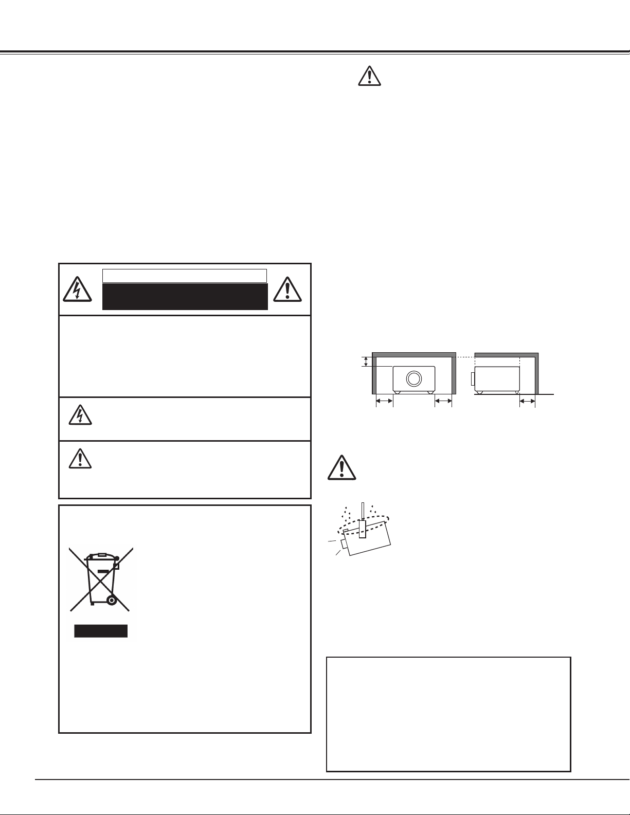
– Allowing the proper amount of space on the top, sides,
and rear of the projector cabinet is critical for proper
air circulation and cooling of the unit. The diagrams
shown here indicates the minimum space required.
If the projector is to be built into a compartment or
similarly enclosed, these minimum distances must be
maintained.
– Do not cover the ventilation slots on the projector. Heat
build-up can reduce the service life of your projector, and
can also be dangerous.
SIDE and TOP REAR
TH IS SYMBOL INDI CATE S THAT DANGE ROUS
VOLTAGE CONSTITUTING A RISK OF ELECTRIC
SHOCK IS PRESENT WITHIN THIS UNIT.
TH I S SYM B O L I NDICATES TH AT TH ERE ARE
IMPORTANT OPER ATING AND MAINT ENANCE
INSTRUCTIONS IN THE OWNER’S MANUAL WITH
THIS UNIT.
NOTE: This symbol and recycle system are applied only to EU countries
and not applied to the countries in the other area of the world.
Your SANYO product is designed and
manufactured with high quality materials
and components which can be recycled
and reused.
This symbol means that electrical and
electronic equipment, at their end-of-life,
should be disposed of separately from
your household waste.
Please dispose of this equipment at your local community
waste collection/recycling centre.
In the European Union there are separate collection
systems for used electrical and electronic products.
Please help us to conserve the environment we live in!
READ AND KEEP THIS OWNER'S MANUAL FOR LATER
USE.
– If the projector is unused for an extended time, unplug
the projector from the power outlet.
CAUTION ON HANGING FROM THE CEILING
When hanging the projector from the
ceiling, clean the air intake vents and
top of the projector periodically with a
vacuum cleaner. If you leave the projector
unclean for a long time, the cooling fans
can be clogged with dust, and it may
cause a breakdown or a disaster.
DO NOT SET THE PROJECTOR IN GREASY, WET, OR
SMOK Y CONDI TIO NS SUCH AS IN A KITCH EN TO
PREVENT A BREAKDOWN OR A DISASTER. IF THE
PR OJECTOR COMES IN CONTACT WI TH OIL OR
CHEMICALS, IT MAY BECOME DETERIORATED.
CAUTION
Not for use in a computer room as defined in the
Standard for the Protection of Electronic Computer/Data
Processing Equipment, ANSI/NFPA 75.
Ne peut être utilisé dans une salle d’ordinateurs telle
que définie dans la norme ANSI/NFPA 75 Standard for
Protection of Electronic Computer/Data Processing
Equipment.
4
Safety Instructions
All the safet y and operating instructions should be read
before the product is operated.
Read all of the instructions given here and retain them for
late r use. Unplug this projector from AC power sup ply
before cleaning. Do not use liquid or aerosol cleaners. Use a
damp cloth for cleaning.
Follow all warnings and instructions marked on the projector.
For added protection to the projector during a lightning
storm, or when it is left unattended and unused for long
periods of time, unplug it from the wall outlet. This will
prevent damage due to lightning and power line surges.
Do not expo se this unit to rain or use near wat er... for
example, in a wet basement, near a swimming pool, etc...
Do no t us e at t achm e nt s no t rec o mm e n de d by th e
manufacturer as they may cause hazards.
Do not place this projector on an unstable cart, stand, or
table. The projector may fall, causing serious injury to a child
or adult, and serious damage to the projector. Use only with
a cart or stand recommended by the manufacturer, or sold
with the projector. Wall or shelf mounting should follow the
manufacturer's instructions, and should use a mounting kit
approved by the manufacturers.
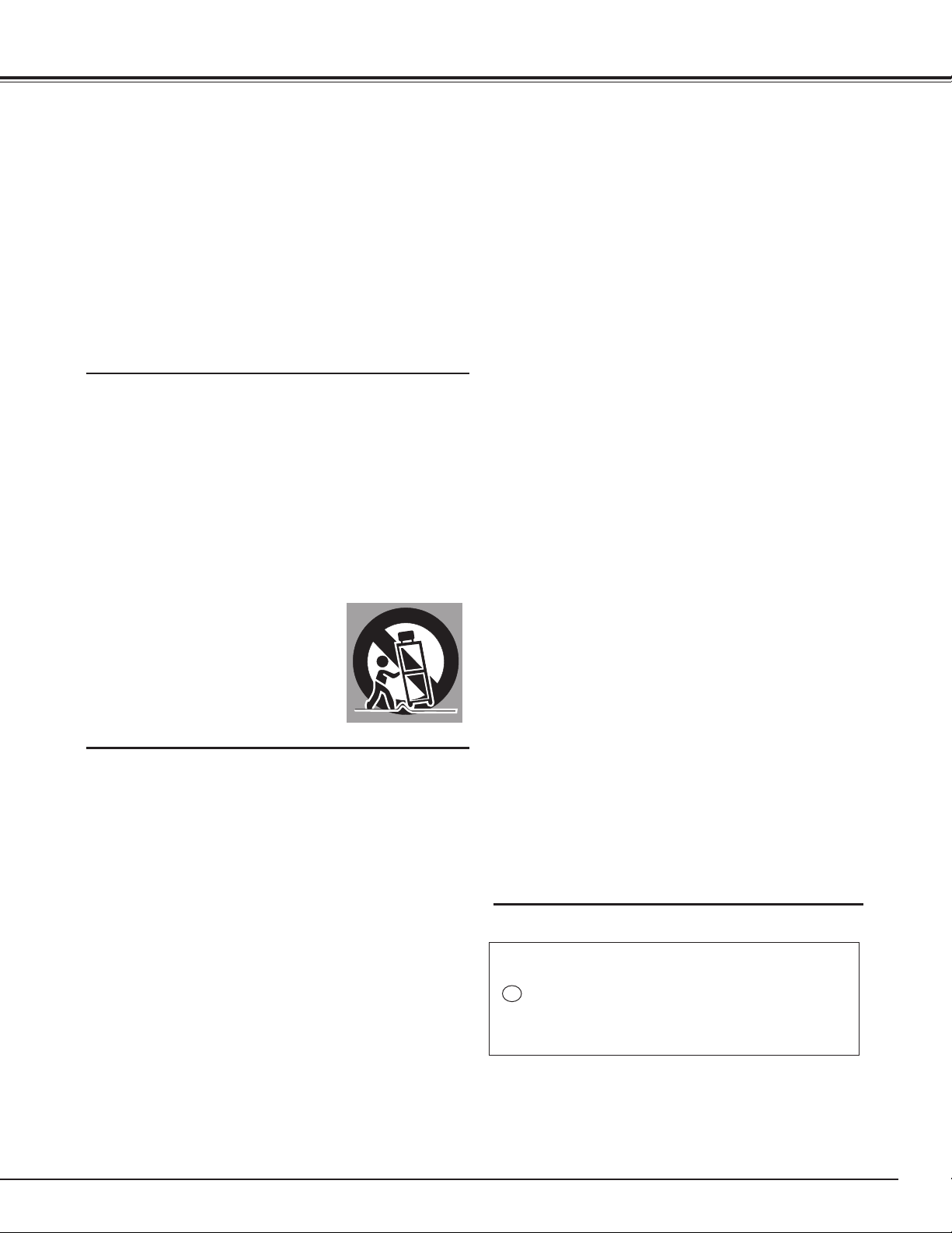
An appl i a n c e and ca r t combi n a t i o n
shou l d be mo v e d wit h car e . Qui ck
st o p s , exc e ssive fo r c e, and une ven
surfaces may cause the appliance and
cart combination to overturn.
This projector should be operated only from the type of
power source indicated on the marking label. If you are not
sure of the type of power supplied, consult your authorized
dealer or local power company.
Do not overload wall outlets and extension cords as this
can result in fire or electric shock. Do not allow anything to
rest on the power cord. Do not locate this projector where
the cord may be damaged by persons walking on it.
Do not attempt to service this projector yourself as opening
or removing covers may expose you to dangerous voltage
or other hazards. Refer all servicing to qualified ser vice
personnel.
Unplug this projector from wall outlet and refer servicing to
qualified service personnel under the following conditions:
a. When the power cord or plug is damaged or frayed.
b. If liquid has been spilled into the projector.
c. If the projector has been exposed to rain or water.
d. If the projector does not operate normally by following
the operating instructions. Adjust only those controls
th a t are cov e r e d by th e operati n g instru c t i o n s as
improper adjustment of other controls may result in
damag e and wi ll oft en requi re extensive work by a
qualified technician to restore the projector to normal
operation.
e. If the projector has been dropped or the cabinet has
been damaged.
f. Whe n the pr o j e c t o r ex h ib i t s a d is t i n ct ch a n g e in
performance-this indicates a need for service.
When replacement parts are required, be sure the service
technician has used replacement parts specified by the
manufacturer that have the same characteristics as the
original part. Unauthorized substitutions may result in fire,
electric shock, or injury to persons.
Slots and openings in the back and bottom of the cabinet are
provided for ventilation, to ensure reliable operation of the
equipment and to protect it from overheating.
The openings should never be covered with cloth or other
materials, and the bottom opening should not be blocked
by placing the projector on a bed, sofa, rug, or other similar
surface. This projector should never be placed near or over a
radiator or heat register.
This projector should not be placed in a built-in installation
such as a book case unless proper ventilation is provided.
Never push objects of any kind into this projector through
cabinet slots as they may touch dangerous voltage points
or short out parts that could result in a fire or electric shock.
Never spill liquid of any kind on the projector.
Do not install the projector near the ventilation duct of airconditioning equipment.
Upon completion of any service or repairs to this projector,
as k th e ser vice techn i c ian to per form rout i n e safety
checks to determine that the projector is in safe operating
condition.
NOTE FOR CUSTOMERS IN THE US
Hg LAMP(S) INSIDE THIS PRODUCT CONTAIN MERCURY
AND MUST BE RECYCLED OR DISPOSED OF ACCORDING
TO LOCAL, STATE OR FEDERAL LAWS.
5
Safety Instructions
Air Circulation
Openings in the cabinet are provided for ventilation. To
ensure reliable operation of the product and to protect
it from overheating, these openings must not be
blocked or covered.
CAUTION
Hot air is exhausted from the exhaust vent. When
using or installing the projector, the following
precautions should be taken.
– Do not put any flammable object or spray can near
the projector, hot air is exhausted from the air vents.
– Keep the exhaust vent at least 3’ (1 m) away from
any objects.
– Do not touch peripheral parts of the exhaust vent,
especially screws and metallic parts. These areas will
become hot while the projector is being used.
– Do not put anything on the cabinet. Objects put on
the cabinet will not only get damaged but also may
cause fire hazard by heat.
– Do not cover vents with papers or other materials.
– Make sure that there are no objects under the
projector. An object under the projector may prevent
the projector from taking cooling air through bottom
vent.
Cooling fans are provided to cool down the projector.
The fans’ running speed is changed according to the
temperature inside the projector.
IMPORTANT!
Filter Maintenance!!
The projector uses a lamp which generates
significant heat. The cooling fans and air vents are
provided to dissipate the heat by drawing air into the
housing and the filter is located in the intake vents to
prevent dust from getting inside of the projector.
In order to care for the projector appropriately,
regular cleaning is required. Remove any dirt or dust
that has accumulated on the projector.
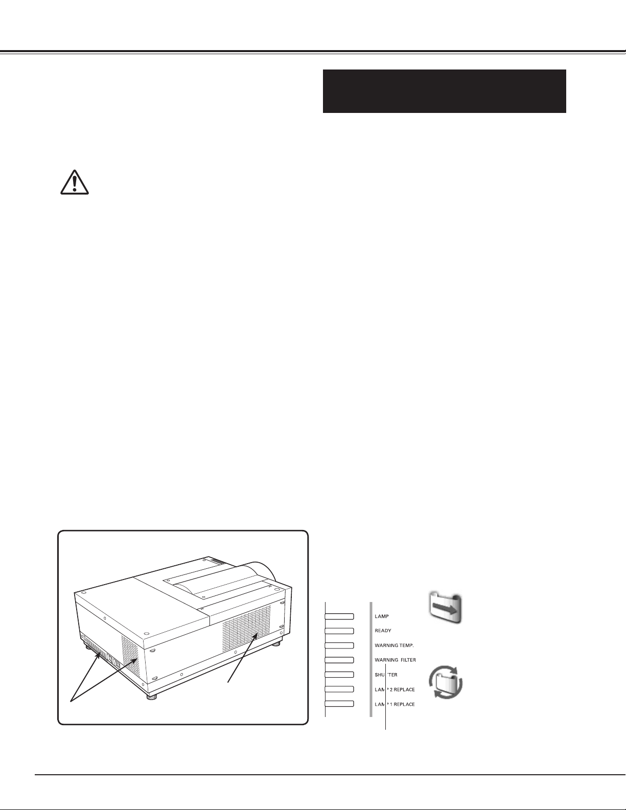
If the projector reaches a time set in the timer
setting, a Filter replacement icon (Fig. 1) appears on
the screen and WARNING FILTER indicator on the
top panel lights up (see below), indicating that the
filter replacement is necessary.
If the projector detects that the filter is clogged and
no scroll is left in the filter cartridge, a Filter cartridge
replacement icon (Fig. 2) appears on the screen and
WARNING FILTER indicator on the top panel lights
up (see below). Stop using the projector immediately
and replace the filter cartridge.
Blocking the air vents and leaving the projector
uncleaned for a long time may not only damage the
projector and may require costly repairs but may also
cause accidents or fire.
For maintenance of the filter, refer to “Filter counter”
on page 56 and “Maintenance and Care” on pages
57–59.
6
EXHAUST VENT
AIR INTAKE VENT
Damages to the projector caused by using an
uncleaned filter or improper maintenance will
void the warranty on the projector.
Top Panel
Fig.1
Filter replacement icon
Fig.2 Filter cartridge replacement
icon
WARNING FILTER
indicator
Safety Instructions
10˚
10˚
10˚ 10˚
10˚
10˚
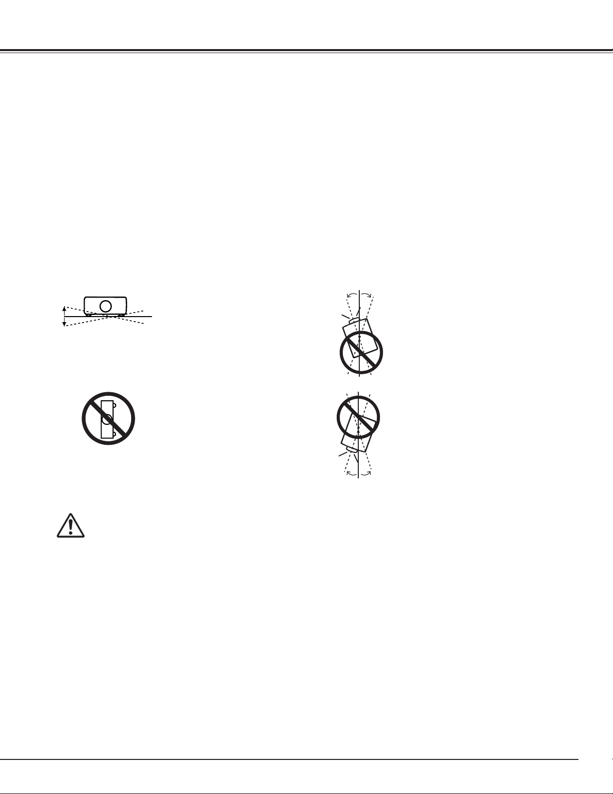
Installing the Projector in Proper Directions
Use the projector properly in specified positions. Improper positioning may reduce the lamp life and result in
severe accident or fire hazard.
This projector can project the picture in upward, downward, or inclined position in perpendicular direction to the
horizontal plane.
✔Note:
•When the image is top/bottom and left/right reversed, set the ceiling function to “On.” (pp. 40, 44)
•The projector can not be operated at an altitude above 3,000 meters.
Positioning Precautions
Avoid positioning the projector as described below when installing.
Do not roll the projector more
than 10 degrees from side to
side.
Do not put the projector
on either side to project an
image.
In upward projection, do
not tilt the projector over 10
degrees right and left.
In downward projection, do
not tilt the projector over 10
degrees right and left.
CAUTION ON CEILING MOUNTING
For ceiling mounting, you need the ceiling mount kit designed for this projector. When not mounted
properly, the projector may fall, causing hazards or injury. For details, consult your dealer. The warranty
on this projector does not cover any damage caused by use of any non-recommended ceiling mount kit
or installation of the ceiling mount kit in an improper location.
7
Safety Instructions
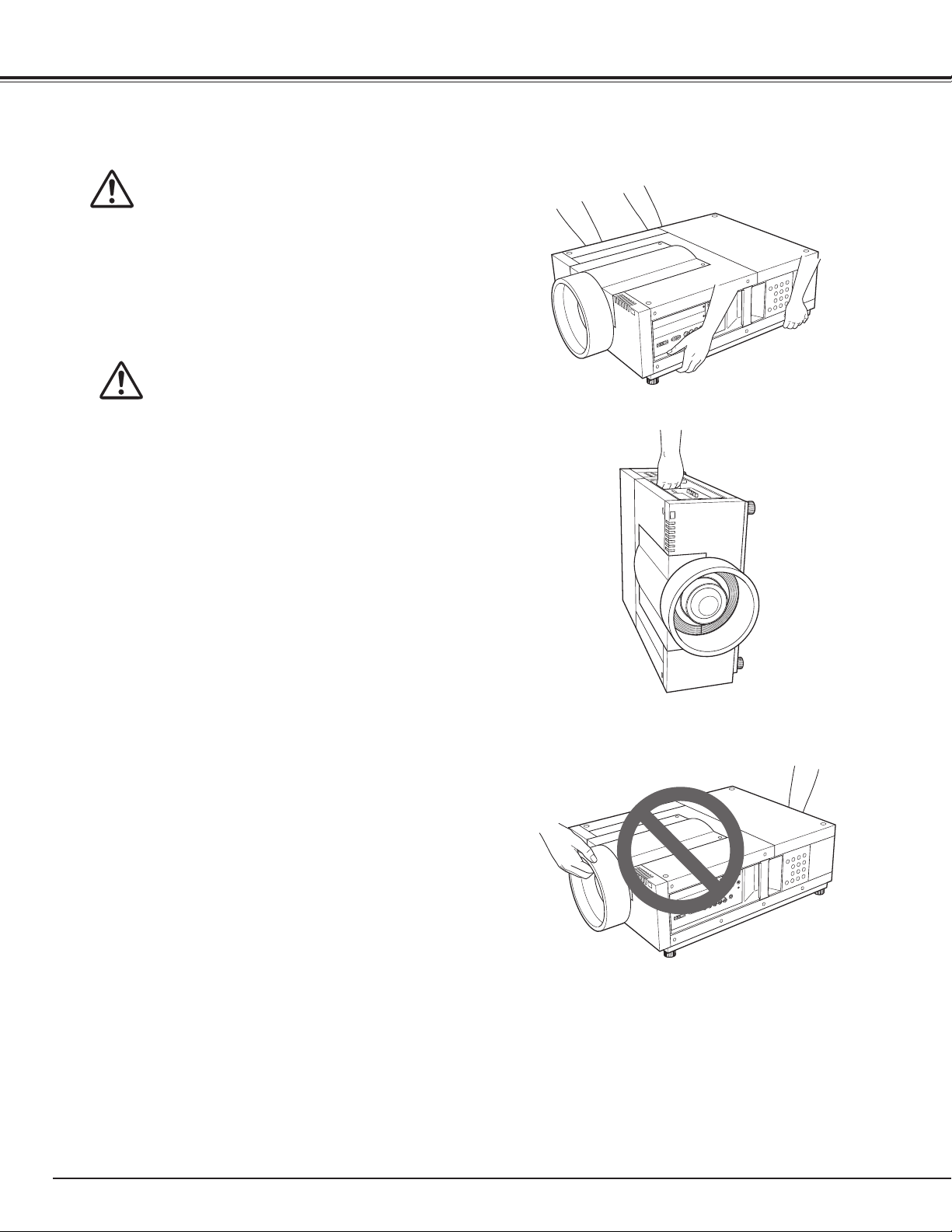
Moving the Projector
Retract the adjustable feet to prevent damage
to lens and cabinet. For safety, holding the
projector on both sides by 2 or more people is
recommended to move the projector because
the projector is heavy. When moving the
projector by one person from necessity, hold
the handle carefully. Do not hold the lens
mount cover. Moving it improperly may result
in damage of cabinet or person's injury.
CAUTION IN CARRYING OR
TRANSPORTING THE PROJECTOR
– Do not drop or bump the projector, otherwise
damages or malfunctions may result.
– When carrying the projector, use a suitable carrying
case.
– Do not transport the projector by courier or any
other transport service in an unsuitable transport
case. This may cause damage to the projector. For
information about transporting the projector by
courier or any other transport service, consult your
dealer.
– Do not put the projector in a case before it is
cooled enough.
– Do not transport the projector with a replacement
lens installed.
8
ASA
Compliance
GROUND
Federal Communications Commission Notice
This equipment has been tested and found to comply with the limits for a Class A digital device,
pursuant to Part 15 of FCC Rules. These limits are designed to provide reasonable protection against
harmful interference when the equipment is operated in a commercial environment. This equipment
generates, uses, and can radiate radio frequency energy and, if not installed and used in accordance
with the instruction manual, may cause harmful interference to radio communications. Operation of
this equipment in a residential area is likely to cause harmful interference in which case the user will be
required to correct the interference at his own expense.
Do not make any changes or modifications to the equipment unless otherwise specified in the
instructions. If such changes or modifications should be made, you could be required to stop operation
of the equipment.
Canadian Radio Interference Regulations
This Class A digital apparatus meets all requirements of the Canadian ICES-003.
WARNING
This is a Class A product. In a domestic environment this product may cause radio interference in
which case the user may be required to take adequate measures.
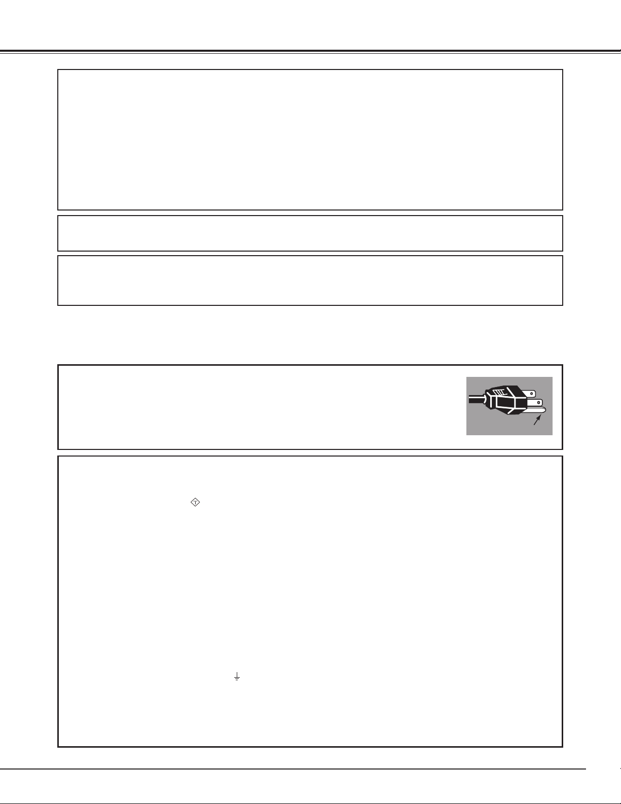
AC Power Cord Requirement
The AC Power Cord supplied with this projector meets the requirement for use in the country you purchased it.
AC Power Cord for the United States and Canada:
AC Power Cord used in the United States and Canada is listed by the Underwriters
Laboratories (UL) and certified by the Canadian Standard Association (CSA).
AC Power Cord has a grounding-type AC line plug. This is a safety feature to be sure
that the plug will fit into the power outlet. Do not try to defeat this safety feature.
Should you be unable to insert the plug into the outlet, contact your electrician.
AC Power Cord for the United Kingdom:
This cord is already fitted with a moulded plug incorporating a fuse, the value of which is indicated on the pin
face of the plug. Should the fuse need to be replaced, an ASTA approved BS 1362 fuse must be used of the
same rating, marked thus
replacement fuse cover is required, ensure it is of the same colour as that visible on the pin face of the plug (i.e.
red or orange). Fuse covers are available from the Parts Department indicated in your User Instructions.
If the plug supplied is not suitable for your socket outlet, it should be cut off and destroyed.
The end of the flexible cord should be suitably prepared and the correct plug fitted.
WARNING: A PLUG WITH BARED FLEXIBLE CORD IS HAZARDOUS IF ENGAGED IN A LIVE SOCKET
OUTLET.
The Wires in this mains lead are coloured in accordance with the following code:
Green-and-yellow ············· Earth
Blue ································· Neutral
Brown ······························ Live
As the colours of the wires in the mains lead of this apparatus may not correspond with the coloured markings
identifying the terminals in your plug proceed as follows:
The wire which is coloured green-and-yellow must be connected to the terminal in the plug which is marked by the
letter E or by the safety earth symbol or coloured green or green-and-yellow.
The wire which is coloured blue must be connected to the terminal which is marked with the letter N or coloured
black.
The wire which is coloured brown must be connected to the terminal which is marked with the letter L or coloured
red.
WARNING: THIS APPARATUS MUST BE EARTHED.
. If the fuse cover is detachable, never use the plug with the cover omitted. If a
THE SOCKET-OUTLET SHOULD BE INSTALLED NEAR THE EQUIPMENT AND EASILY ACCESSIBLE.
9
Part Names and Functions
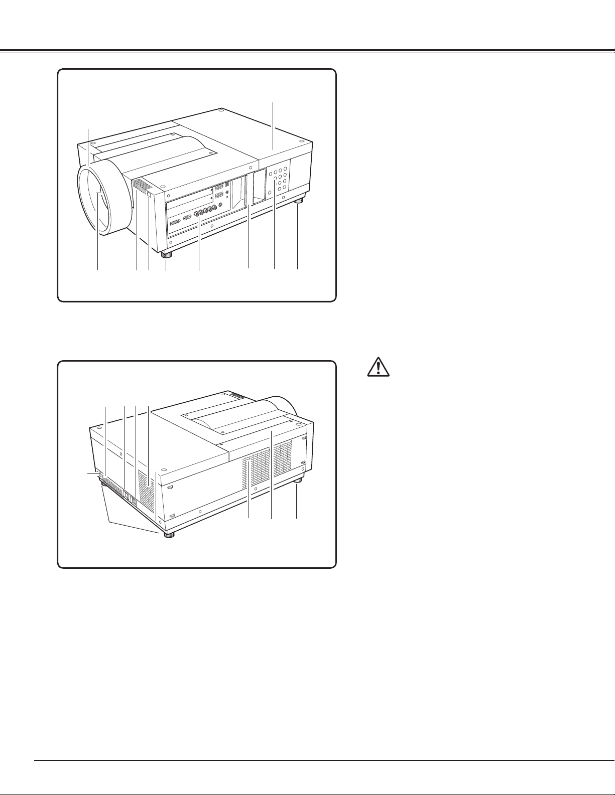
Front
q
w
Back
e
!2
!1 !3
r
!1
t
y
u
o
i
t
qLens Mount Cover
wProjection Lens (Option)
e Indicators
rInfrared Remote Receiver (Front)
t Adjustable Feet
Terminals and Connectors
y
u Handle
i Side Control
o Lamp Cover
!0 Infrared Remote Receiver (Rear)
Exhaust Vent
!1
CAUTION
Hot air is exhausted from the exhaust
vent. Do not put heat-sensitive objects
near this side.
!0
t
!2Main On/Off Switch
✽
!5
!4
t
!3 Power Cord Connector
!4 Air Intake Vent
!5 Air Filter
✽Kensington Security Slot
This slot is for a Kensington lock used
to deter theft of the projector.
* Kensington is a registered trademark of ACCO Brands
Corporation.
10
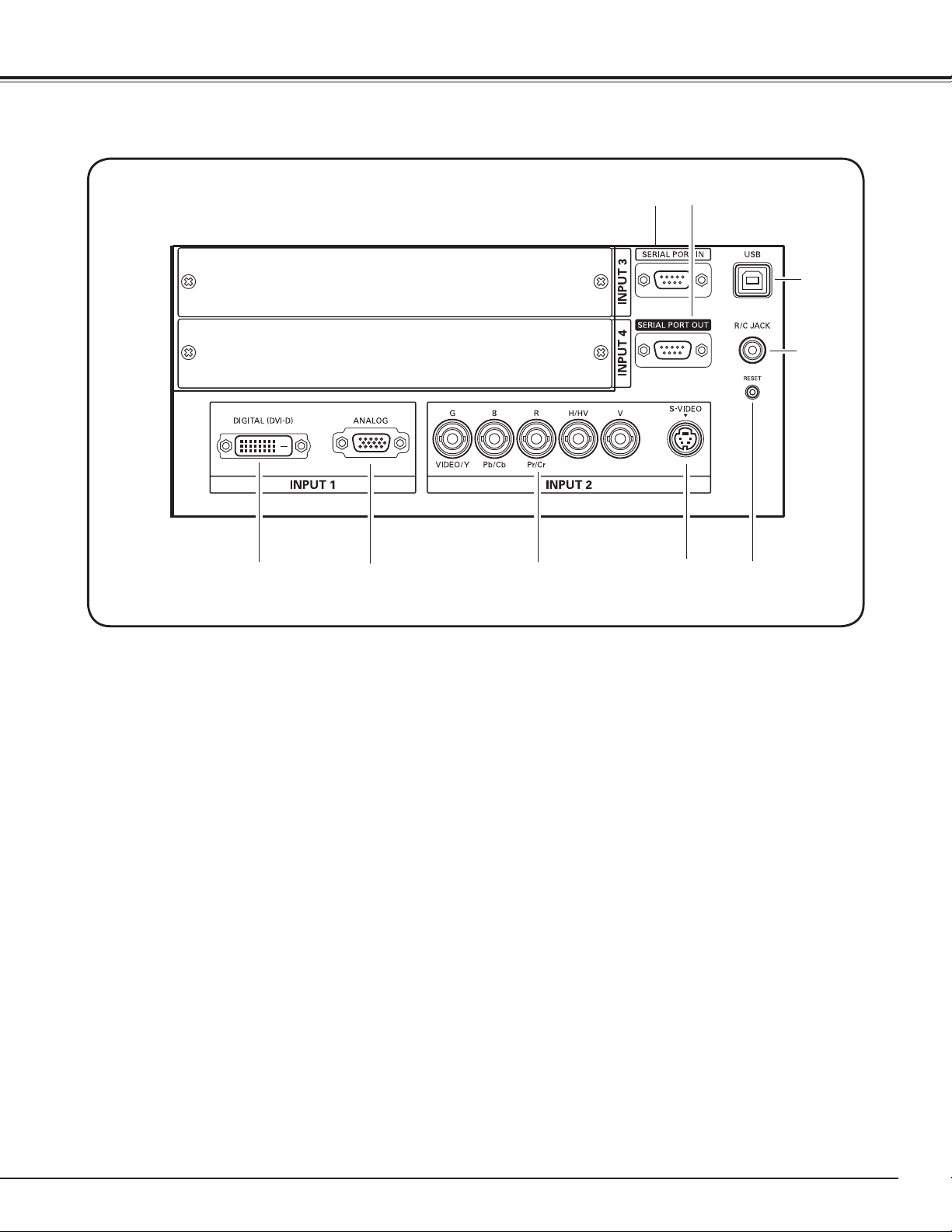
Terminals and Connectors
Part Names and Functions
q
w
e
r
t
q
SERIAL PORT IN TERMINAL
If you control the projector by computer, you must
connect a cable (not supplied) from your computer
to this terminal.
w
SERIAL PORT OUT TERMINAL
This terminal outputs signal from SERIAL PORT IN.
More than two projectors can be controlled with
one computer by connecting SERIAL PORT IN of
another projector to this terminal.
eUSB CONNECTOR (Series B)
USB connector is to used to service the projector.
rR/C JACK
When using the wired remote control, connect the
wired remote control to this jack with a remote
control cable (not supplied).
[ RESET button
A built-in micro processor which controls this unit may
occasionally malfunction and need to be reset. This can be done
by pressing the RESET button with a pen, which will shut down
and restart the unit. Do not use the RESET function excessively.
y
u
t
DVI INPUT TERMINAL
Connect computer output (Digital/DVI-D type) to
this terminal. (Refer to p.20)
HD (HDCP Compatible) signal can be also
connected. (Refer to p.21)
y
D-sub 15-PIN INPUT TERMINAL
Connect computer output (Analog D-sub 15-pin
type) to this terminal.
(Refer to p.20)
u5 BNC INPUT JACKS
Connect the component or composite video
output signal from video equipment to VIDEO/Y,
Pb/Cb, and Pr/Cr jacks or connect the computer
output signal (5 BNC Type [Green, Blue, Red,
Horiz. Sync, and Vert. Sync.]) to G, B, R, H/V, and V
jacks (pp.20–21).
iS-VIDEO INPUT JACK
Connect the S-VIDEO output signal from video
equipment to this jack (p.21).
i
✽
11
Part Names and Functions
Side Control and Indicators
INDICATORS
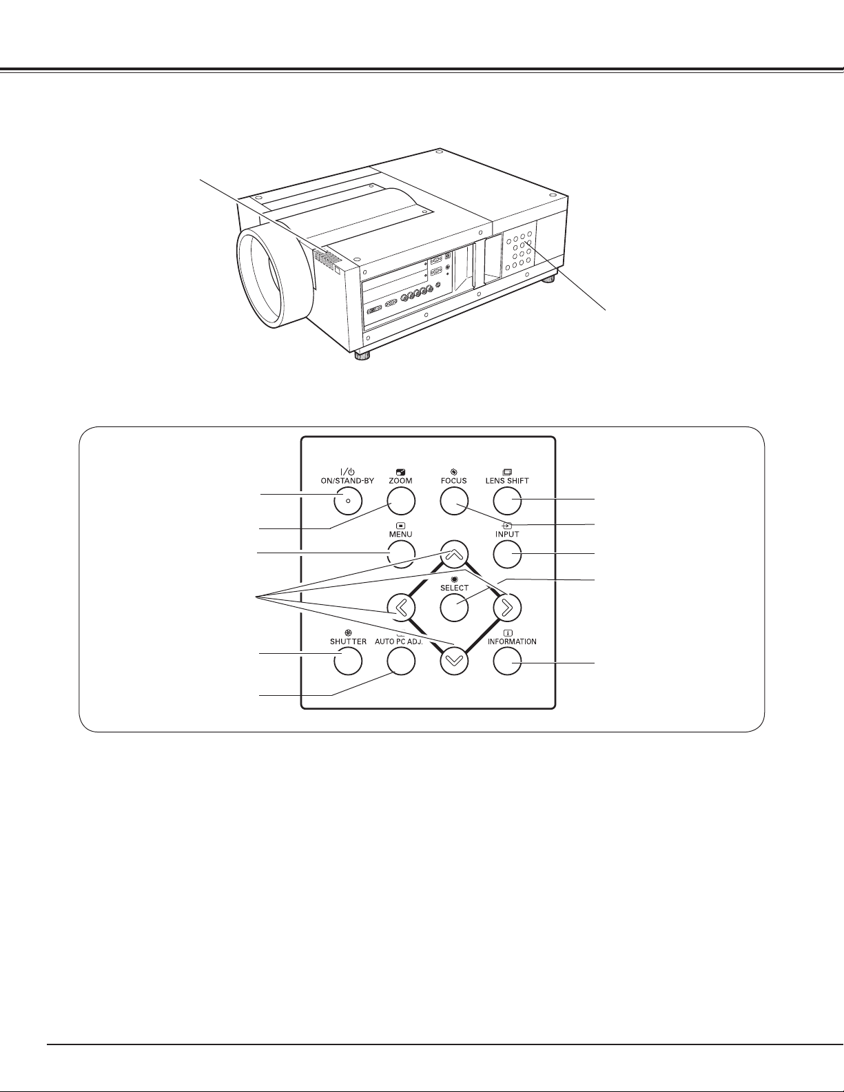
Side Controls
SIDE CONTROLS
q
w
e
r
t
y
q
ON/STAND-BY
Turn the projector on or off. (pp.23,24)
wZOOM button
Zoom in and out the images. (p.27)
e
MENU
Open or close the On-Screen MENU. (pp.25, 26)
r
POINT
- Select an item or adjust the value in the OnScreen MENU.
- Pan the image in DIGITAL ZOOM + mode. (p.40)
t
SHUTTER button
Close and open up the built-in shutter. (p.27)
y
AUTO PC ADJ.
Automatically adjust the computer image to its
optimum setting. (p.27)
button
button
buttons
button
u
i
o
!0
!1
u
LENS SHIFT
Select the LENS SHIFT function. (p.27)
i
FOCUS
Adjust the focus. (p.27)
o INPUT
Select an input source INPUT 1, INPUT 2, Input 3
or Input 4. (pp.31-33)
!0
SELECT
Used to execute the selected item. It is also used
to expand image in DIGITAL ZOOM mode. (p.40)
!1 INFORMATION button
Display the input source information (p.28).
button
button
button
button
12
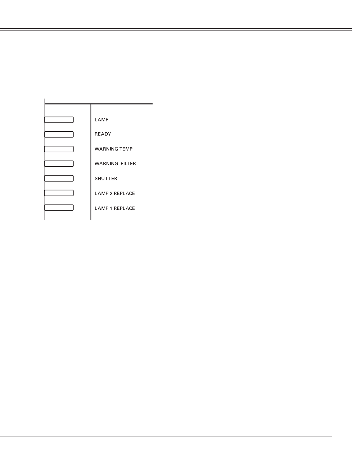
Indicators
q
Part Names and Functions
q
LAMP Indicator
This indicator is dim when the projector is turned
on. And bright when the projector is in stand-by
mode. (pp.72-74)
w
e
r
t
y
u
w
READY indicator
This indicator lights green when the projector is
ready to be turned on. And it flashes green in
Power Management mode. (pp.52, 72-74)
e
WARNING TEMP. indicator
This indicator flashes red when internal projector
temperature is too high. (pp.65, 72-74)
r
WARNING FILTER indicator
– Blink slow when the filter is being scrolled (pp.
57, 72).
– Blink fast when the filter scroll is not working
properly or the filter cartridge is not installed
(pp.57, 74).
– Light orange when the clogging of the filter is
detected or the filter counter reaches a time set
in the timer setting, urging immediate filter/ filter
cartridge replacement (pp.56, 57, 74).
t
SHUTTER indicator
Light blue when the shutter is closed. (p72)
y
LAMP 2 REPLACE indicator
Turn orange when the life of the projection lamp2
draws to an end. (p.61, 73)
u
LAMP 1 REPLACE indicator
Turn orange when the life of the projection lamp1
draws to an end. (p.61, 73)
13
Part Names and Functions
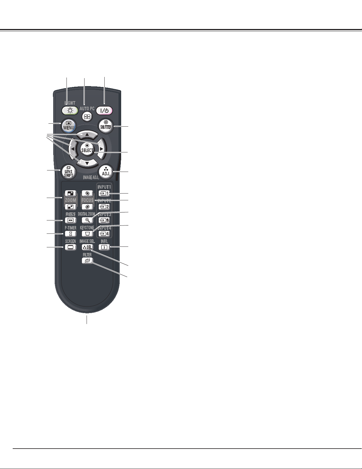
Remote Control
e
w
r
t
y
u
i
o
!0
@1
✔Note:
To ensure safe op e ratio n, ob s er ve the
following precautions:
• Do not bend, drop, or expose the remote
control to moisture or heat.
• For cleaning, use a soft dry cloth. Do not
apply benzene, thinner, splay, or any other
chemical materials.
q
!1
!2
!3
!4
!5
!6
!7
!8
!9
@0
q
ON/STAND-BY button
Turn the projector on or off. (pp.23-24)
w
AUTO PC button
Automatically adjust the computer image to its optimum
setting (pp.29, 35).
e
LIGHT button
Light the buttons on the remote control for about 10
seconds.
r
MENU button
Open or close the On-Screen MENU. (pp.25-26)
t POINT ed 7 8 buttons
– Select an item or adjust the value in The ON-SCREEN MENU.
–Pan the image in DIGITAL ZOOM +/– mode. (p.40)
y
LENS SHIFT button
Select the LENS SHIFT function. (p.27, 29)
u
ZOOM buttons
Zoom in and out the images.
i
FREEZE button
Freeze the picture on the screen. (p.29)
o
P-TIMER button
Operate the P-TIMER function. (p.30)
!0 SCREEN button
Select the screen size (pp.39-40).
!1
SHUTTER button
Close the built-in shutter for light blocking. (p27, 30)
!2
SELECT
button
–Execute the selected item.
– Expand or compress the image in the DIGITAL ZOOM
mode. (p.40)
!3
IMAGE ADJ. button
Enter the image level adjustment mode. (pp.45-47)
!4
INPUT 1, 2, 3, 4
button
s
Select an input source. (pp.31-33)
!5
FOCUS buttons
Adjust the focus. (p.29)
!6D.ZOOM
button
Select the Digital zoom +/- mode and resize the image (p.40).
!7
KEYSTONE button
Correct keystone distortion. (pp.30, 40, 44)
!8 INFO. button
Display the input source information (p.28).
!9
IMAGE SEL. button
Select the image level. (pp.38, 42)
@0FILTER button
Scroll the filter (p.30).
@1
Wired Remote Jack
Connect the remote control cable (not supplied) to this jack
when using as a wired remote control.
14
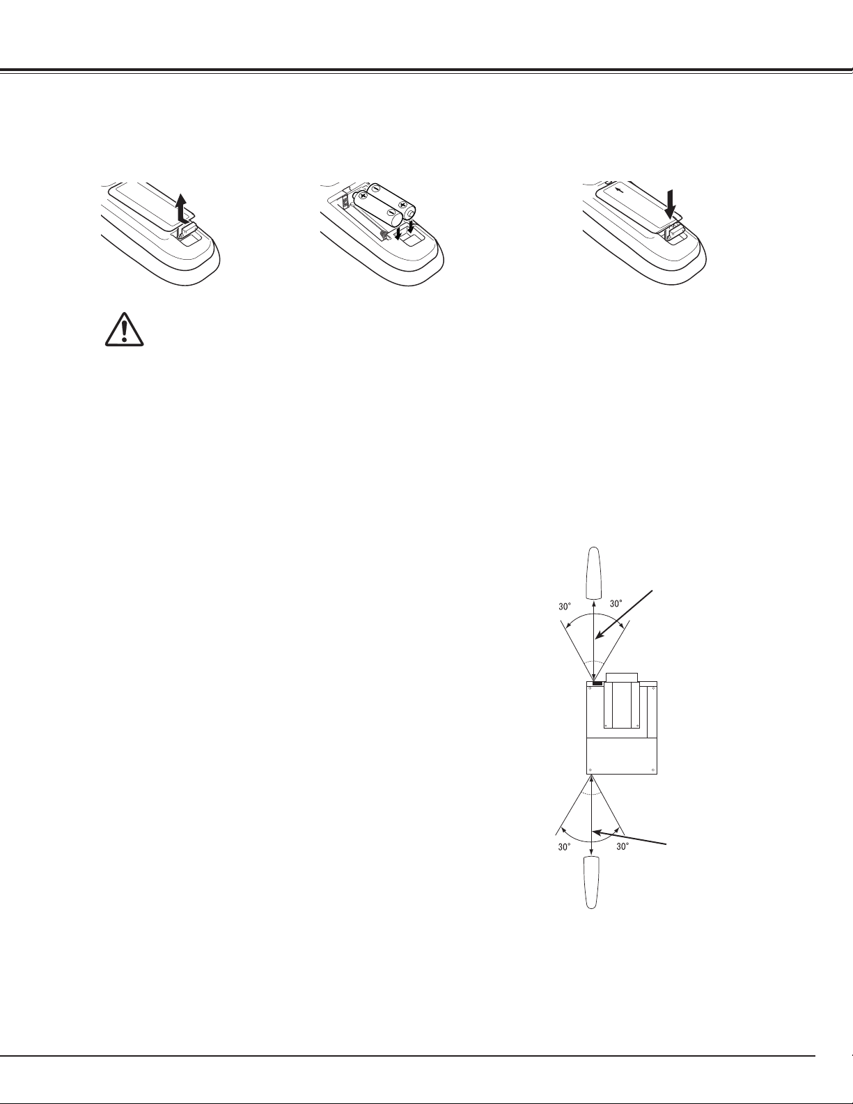
Remote Control Battery Installation
Part Names and Functions
Open the battery
compartment lid.
1 2 3
Pull up the lid
and remove it.
To ensure safe operation, please observe the following precautions :
● Use two (2) AA or LR6 type alkaline batteries.
● Always replace batteries in sets.
● Do not use a new battery with a used battery.
● Avoid contact with water or liquid.
● Do not expose the remote control to moisture or heat.
● Do not drop the remote control.
● If the battery has leaked on the remote control, carefully wipe the case clean and install new batteries.
● Risk of an explosion if battery is replaced by an incorrect type.
● Dispose of used batteries according to the instructions.
Install new batteries into
the compartment.
Two AA size batteries
For correct polarity (+ and –),
be sure battery terminals are
in contact with pins in the
compartment.
Remote Control Receivers and Operating Range
Point the remote control toward the projector (to
Infrared Remote Receivers) when pressing the buttons.
Maximum operating range for the remote control is
about 16.4’ (5 m) and 60 degrees in front and rear of the
projector.
Replace the
compartment lid.
16.4’
(5 m)
Infrared Remote Receivers are provided both in front and
back of the projector. You can conveniently use both of
the receivers (pp. 10, 52)
✔Note:
•
When hanging the projector from the ceiling, select the
Infrared Remote Receiver which is located farther away
from the fluorescent light.(p.52)
16.4’
(5 m)
Wired Remote Control
The remote control can be used as a wired remote control. Wired remote control helps you use the remote control outside
of the operating range (16.4’/ 5 m). Connect the remote control and the projector with the remote control cable (sold
separately). Connected with the remote control cable, the remote control does not emit wireless signal.
15
Part Names and Functions
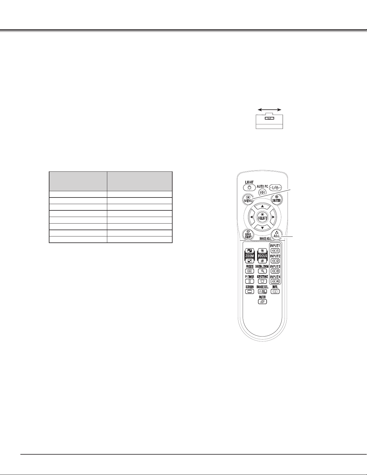
Remote Control Code
The eight different remote control codes (Code 1–Code 8) are assigned to this projector. Switching the remote
control codes prevents interference from other remote controls when several projectors or video equipment
next to each other are operated at the same time. Change the remote control code for the projector first before
changing that for the remote control. See “Remote control” in the Setting Menu on page 52.
Check the Reset Switch to "Use position" in the
1
compartment lid on the back of the remote control.
During holding down the MENU button, press the
2
IMAGE ADJ. button corresponding times to the
number of the remote control code for the projector.
Number of Times
Remote Control Code
Code 1 1
Code 2
Code 3
Code 4 4
Code 5 5
Code 6 6
Code 7 7
Code 8 8
Pressing IMAGE ADJ.
button
2
3
Use positi on
Reset switch
Reset position
ME N U b u tton
IMAGE ADJ.
button
16
Installation
Lens Installation
Before setting up the projector, install Projection Lens on the projector.
Before installation, check where the projector is used and prepare a suitable lens. For the specifications of
Projection Lens, contact sales dealer where you purchased the projector.
- Do not use the optional lens below for this projector. Otherwise damages may result.
LENS MODEL NO. : LNS-T01, LNS-T01Z
- Lens installation and replacement should be made by the qualified service personnel.
- When setting the projector after lens installation, be sure to replace a Lens Cap to protect a
surface.
- When carrying or holding up the projector, be careful not to put your hands on lens part. It may
damage lens, cabinet, or mechanical parts.
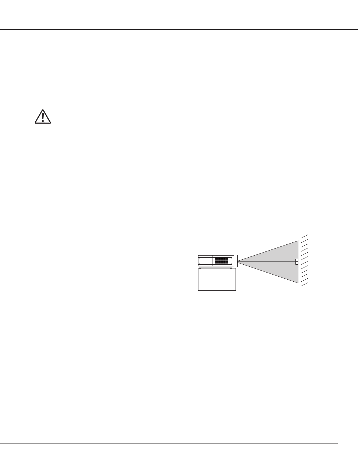
Positioning Projector
This projector is designed to project on a flat projection
surface.
✔Note:
•
Brightness in room has a great influence on picture quality.
It is recommended to limit ambient lighting in order to
provide the best image.
SCREEN
17
Installation
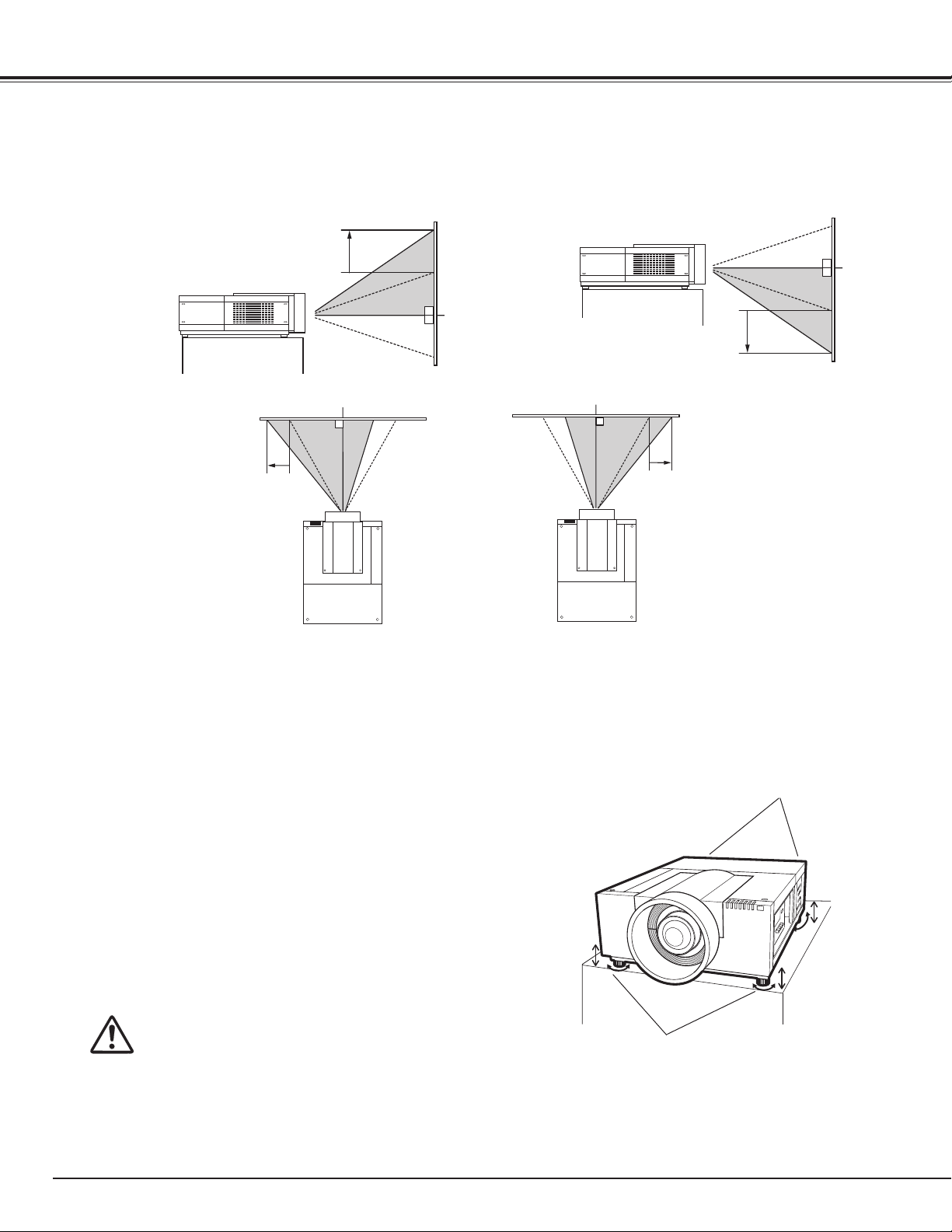
Lens Shift Adjustment
Projection lens can be moved from side to side and up and down with the motor-driven lens shift function. This
function makes the positioning of images easy on the screen.(See page 27)
The display position can be
shifted upward up to 50%
elevation of the display.
The display position can be
shifted downward up to 50%
low level of the display.
When the lens is shifted to top.
When the lens is shifted to bottom.
The display position can be
shifted to the left in up to
10% width of the display.
When the lens is shifted to leftmost.
Picture Level and Pitch Adjustment
The projection angle is adjustable up to 2.8 degrees
upward and downward respectively by rotating front and
back feet .
To raise the projector, rotate the feet clockwise.
To lower the projector or to retract the adjustable feet,
rotate the feet counterclockwise.
To correct keystone distortion, press the KEYSTONE
button on the remote control or select Keystone from the
menu (see pages 14, 30, 40, 44).
The display position can be
shifted to the right in up to
10% width of the display.
When the lens is shifted to rightmost.
REAR ADJUSTABLE
FEET (Refer to p.10)
18
Do not rotate the adjustable feet when you
see the red line on the adjustable feet. The
adjustable feet may fall off.
ADJUSTABLE
FEET
Installation
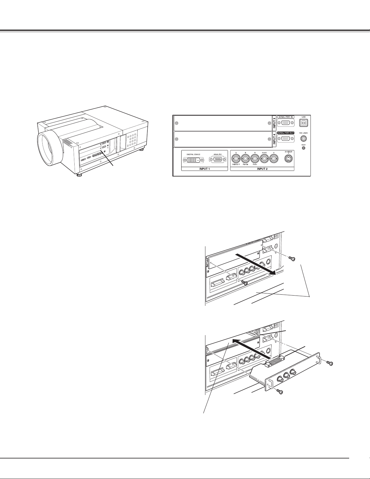
Terminals of Projector
The projector has two replaceable Interface board slots. The projector's functions can be extended by installing
the optional interface boards into the terminal slots. 2 vacant slots (Input 3 and 4) are provided in your
purchasing the projector. For the Optional Interface Boards, contact sales dealer where you purchased the
projector.
2 TERMINAL SLOTS (Factory set)
INPUT/OUTPUT
TERMINALS
DVI / D-sub 15 Terminal 5-BNC / VideoTerminal
Replacement of Terminal
✔Note:
• In the replacement of interface board, turn off the
projector, press the Main On/Off Switch to Off and
unplug the AC power cord from the AC outlet.
Remove 2 Screws from an interface board.
1
Pull out the interface board.
2
Replace the interface board. Insert a new interface
3
board along Guide to fit Plug into Socket.
Tighten screws to secure the interface board.
4
NOTES ON ORDERING OR USING
OPTIONAL INTERFACE BOARD
When ordering or using Optional Interface Board, contact
your sales dealer. When contacting the sales dealer, tell
the Option Control Number (Op.cont.No.) in the menu that
is located on the bottom of the information menu.
(See page 28)
Screws
Guide
Socket
Plug
Figure shows Dual-SDI terminal.
19
Installation
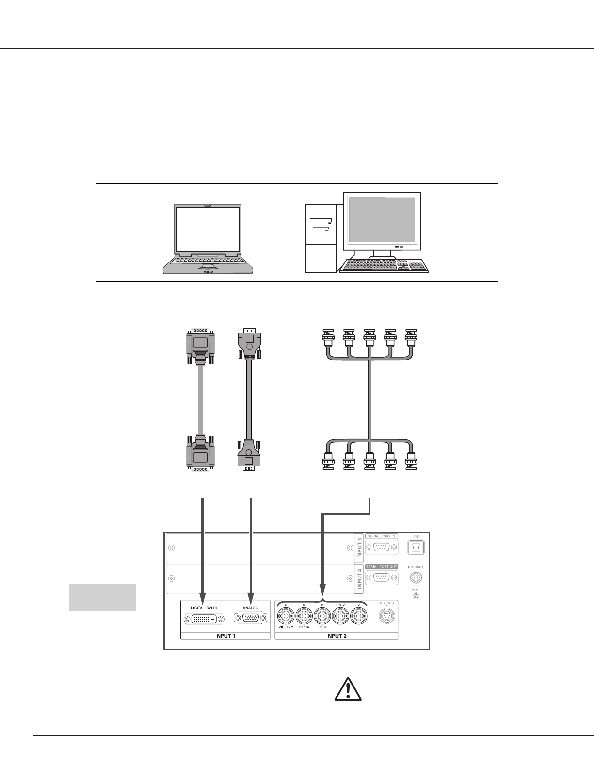
Connecting to Computer
Cables used for connection
• VGA Cable (D-sub 15 pin) *
• DVI Cable
• BNC Cable (BNC x 5)
( *One cable is supplied; Other cables are not supplied with this projector.)
Laptop type
Monitor Output
DVI Cable
DIGITAL
Monitor Output
VGA Cable
ANALOG
Monitor Output
R
B
G
BNC Cable ✽
H/HV
Desktop type
V
20
Terminals of
the projector
Unplug the power cords of both the
projector and external equipment from
the AC outlet before connecting cables.
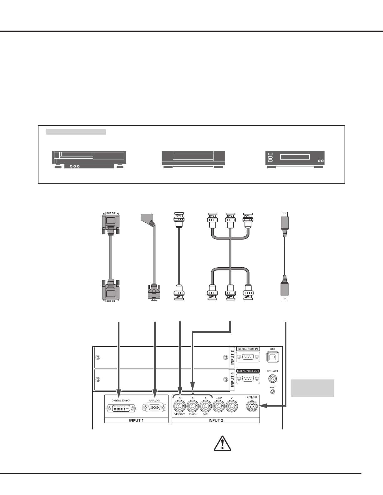
Connecting to Video Equipment
Cables used for connection
• Video Cable (BNC x 3, BNC x 1)
• SCART-VGA Cable
• DVI Cable
• S-Video Cable
( Cables are not supplied with the projector.)
Installation
Video Source (example)
Video Cassette Recorder
Digital Output
(HDCP compatible )
DVI Cable
DIGITAL
RGB SCART
21-pin Output
SCART-VGA
Cable
Video Disc Player
Composite
Video Output
BNC
Cable
VIDEOANALOG
Component video output equipment.
(such as DVD player or
high-definition TV source.)
Component Video Output
Pb/Cb Pr/Cr
Y
BNC
Cable
Y-Pb/Cb-Pr/Cr
S-Video Output
S-Video Cable
S-VIDEO
Terminals of
the projector
Unplug the power cords of both the
projector and external equipment from
the AC outlet before connecting cables.
21
Installation
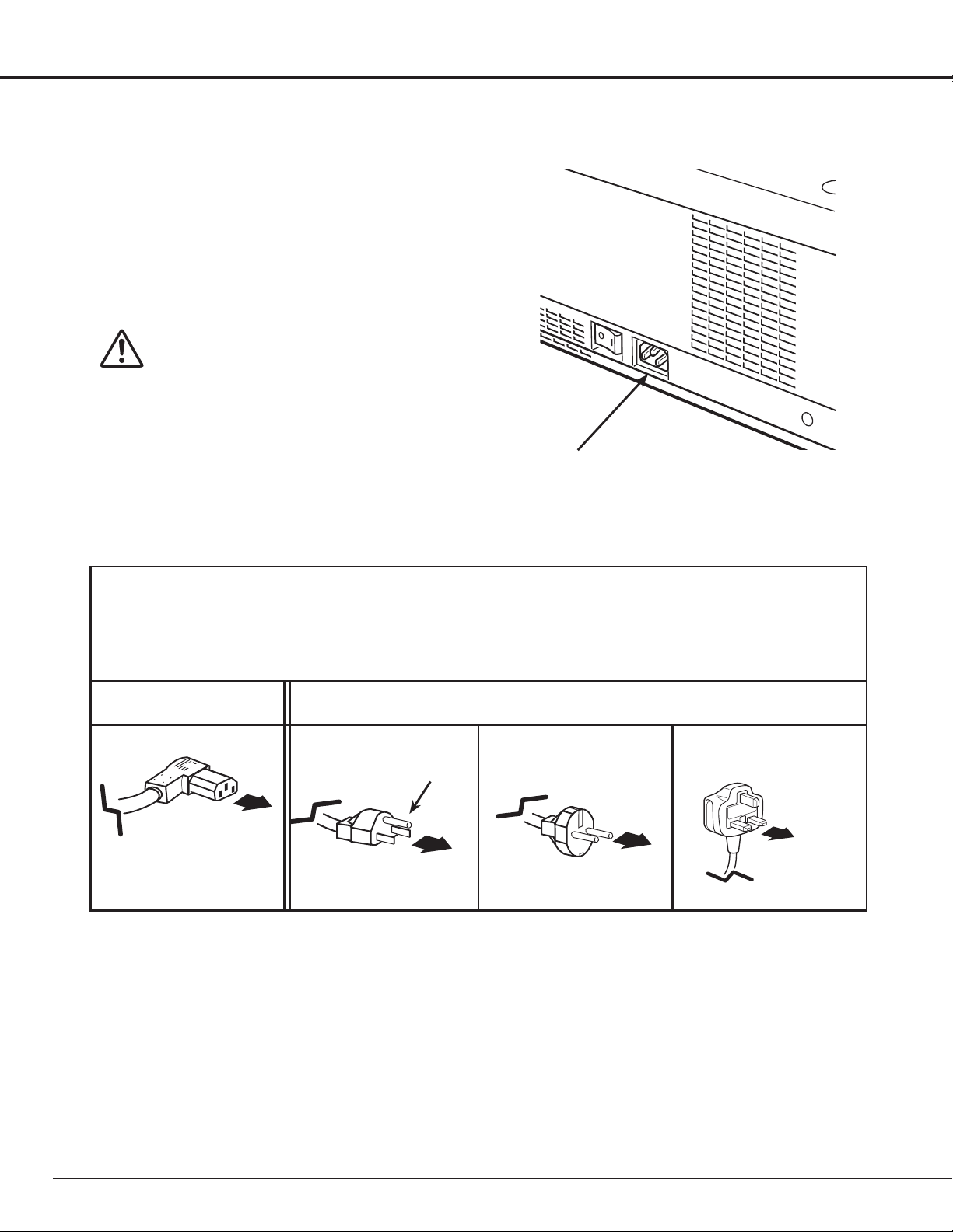
Connecting the AC Power Cord
This projector uses nominal input voltages of 100-120 or 200–240
V AC. It is designed to work with single-phase power systems
having a grounded neutral conductor. To reduce the risk of
electrical shock, do not plug into any other type of power system.
If you are not sure of the type of power being supplied, consult
your authorized dealer or service station.
Connect the projector with all peripheral equipment before turning
on the projector.
CAUTION
The AC outlet must be near this equipment and must be easily
accessible.
✔Note:
Unplug the AC power cord when the projector is not in use.
•
When the projector is connected to an outlet with AC power
cord, it is in stand-by mode and consumes a little electric
power.
Connect the AC power cord (supplied) to the
projector.
NOTE ON THE POWER CORD
AC power cord must meet the requirements of the country where you use the projector.
Confirm the AC plug type with the chart below and proper AC power cord must be used.
If the supplied AC power cord does not match your AC outlet, contact your sales dealer.
Projector side AC Outlet side
For Continental Europe
To the AC Outlet.
(200–240 V AC)
To POWER CORD
CONNECTOR on your
projector.
For the U.S.A. and Canada
Ground
To the AC Outlet.
(120 V AC)
For the U.K.
To the AC Outlet.
(200–240 V AC)
22
Turning On the Projector
Basic Operation
Complete peripheral connections (with a computer,
1
VCR, etc.) before turning on the projector.
Connect the projector’s AC power cord into an AC
2
outlet and turn on the MAIN ON/OFF Switch. The
LAMP indicator lights red and the READY indicator
lights green.
Press the ON/STAND-BY button on the side control
3
or on the remote control. The LAMP indicator
dims red and the cooling fans start to operate. The
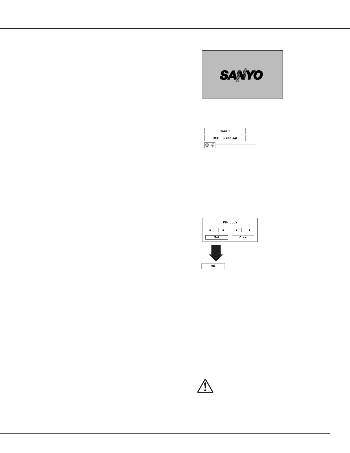
preparation display appears on the screen and the
countdown starts.
After the countdown, the input source that was
4
selected the last time and the Lamp mode icon (see
page 60) appear on the screen.
If the projector is locked with a PIN code, PIN code
Input Dialog Box will appear. Enter the PIN code as
instructed below.
Enter a PIN code
Use the Point ed buttons on the side control or on the
remote control to enter a number. Press the Point 8
button to fix the number and move the red frame pointer
to the next box. The number changes to “✳.” Repeat
this step to complete entering a four-digit number. After
entering the four-digit number, move the pointer to “Set.”
Press the SELECT button so that you can start to operate
the projector.
If you fixed an incorrect number, use the Point 7 button
to move the pointer to the number you want to correct,
and then enter the correct number.
If you entered an incorrect PIN code, “PIN code” and the
number (✳✳✳✳) will turn red for a moment. Enter the
correct PIN code all over again.
What is PIN code?
PIN (Personal Identification Number) code is a security
code that allows the person who knows it to operate the
projector. Setting a PIN code prevents unauthorized use
of the projector.
A PIN code consists of a four-digit number. Refer to the
PIN code lock function in the Setting Menu on page 5354 for locking operation of the projector with your PIN
code.
16
The preparation display will disappear after 20
seconds.
Selected Input Source and Lamp control
Lamp mode
See page 60 for the Lamp control status
✔Note:
• The Lamp replacement icon and the Filter warning
icon may appear on the screen depending on the
usage state of the projector.
PIN code Input Dialog Box
After the OK icon
disappears, you can
operate the projector.
✔Note:
• When the Logo select function is set to “Off,” the
logo will not be shown on the screen (p.49).
• When the “Countdown off” or “Off” is selected
in the Display function, the countdown will not be
shown on the screen (p.48).
• During the countdown period, all operations are
invalid.
• If the correct PIN code number is not entered
within three minutes after the PIN code dialog
box appeared, the projector will be turned off
automatically.
• The “1234” is set as the initial PIN code at the
factory.
CAUTION ON HANDLING PIN CODE
If you forget your PIN code, the projector
can no longer be started. Take special care
in setting a new PIN code; write down the
number in a column on page 80 of this
manual and keep it at hand. Should the
PIN code be missing or forgotten, consult
your dealer or service center.
23
Basic Operation
Turning Off the Projector
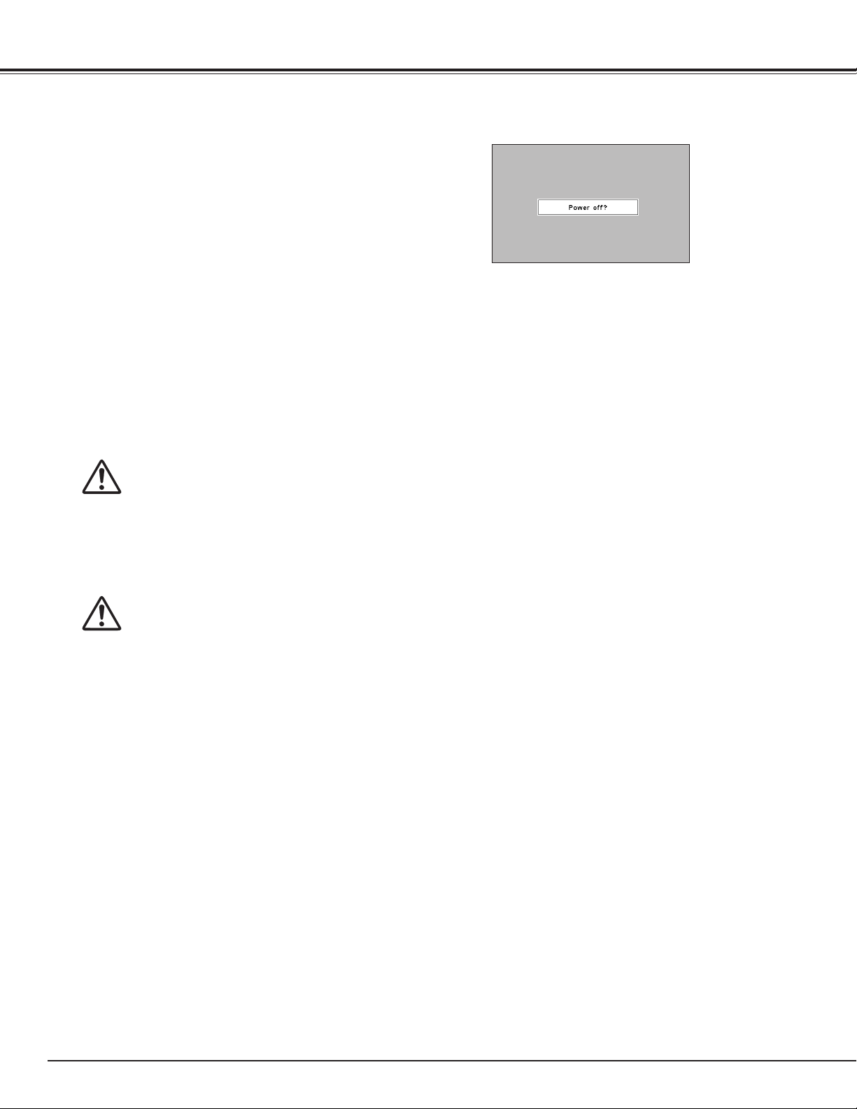
Press the ON/STAND-BY button on the side control
1
or on the remote control, and “Power off?” appears
on the screen.
Press the ON/STAND-BY button on the side control
2
or on the remote control again to turn off the
projector. The LAMP indicator lights bright and the
READY indicator turns off. After the projector is
turned off, the cooling fans operate. You cannot turn
on the projector during this cooling down period.
When the projector has cooled down enough, the
3
READY indicator lights green and then you can turn
on the projector. To turn off the MAIN ON/OFF
Switch, wait until the projector is completely cooled
down.
Unplug the AC power cord from the AC outlet.
4
“Power off?” disappears after 4 seconds.
TO MAINTAIN THE LIFE OF THE LAMP, ONCE YOU
TURN THE PROJECTOR ON, WAIT AT LEAST FIVE
MINUTES BEFORE TURNING IT OFF.
DO NOT UNPLUG THE AC POWER CORD WHILE
COOLING FANS ARE RUNNING OR BEFORE THE
READY INDICATOR LIGHTS GREEN AGAIN.
OTHERWISE IT WILL RESULT IN SHORTENING OF
THE LAMP LIFE.
DO NOT OPERATE THE PROJECTOR CONTINUOUSLY
WITHOUT REST. CONTINUOUS USE MAY RESULT
IN SHORTENING THE LAMP LIFE. TURN OFF THE
PROJECTOR AND LET STAND FOR ABOUT AN HOUR
IN EVERY 24 HOURS.
✔Note:
• When the On start function is set to “On,” the projector
will be turned on automatically by connecting the AC power
cord to an AC outlet (p.53).
• The running speed of cooling fans is changed according to
the temperature inside the projector.
• Do not put the projector in a case before the projector is
cooled enough.
• If the WARNING TEMP. indicator blinks red, see “Warning
Indicators” on page 65.
• The projector cannot be turned on during the cooling
period with the READY indicator turned off. You can turn it
on again after the READY indicator becomes green again.
24
How to Operate the On-Screen Menu
Basic Operation
The projector can be adjusted or set via the On-Screen
Menu. For each adjustment and setting procedure, refer
to the respective sections in this manual.
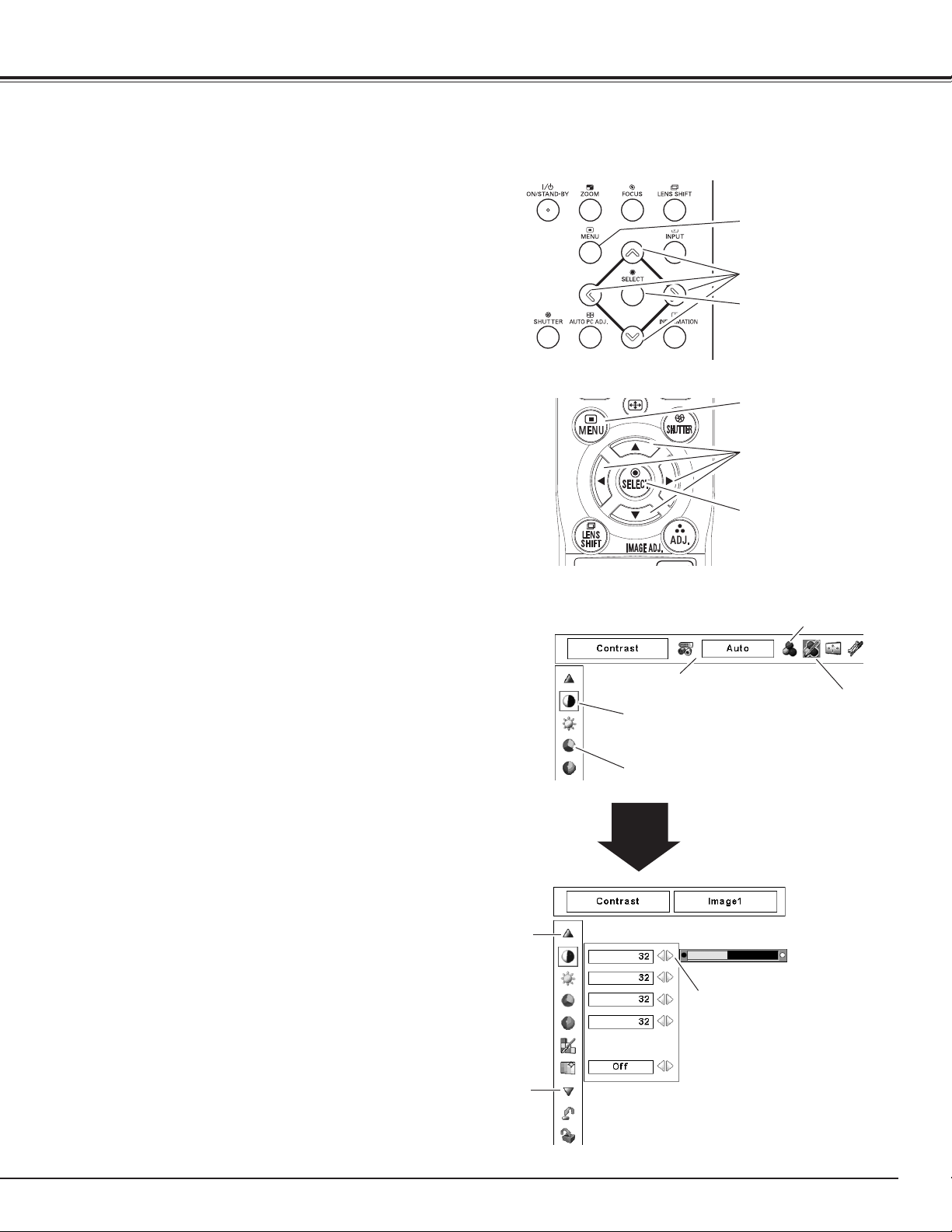
Press the MENU button on the side control or the
1
remote control to display the On-Screen Menu.
Use the Point 7 8 buttons to select a Menu icon.
2
Use the Point ed buttons to select an item in the
selected menu.
Press the SELECT button to show the item data.
3
Use the Point 7 8 buttons to adjust the values.
To close the On-Screen Menu, press the MENU
button again.
✔Note:
• The selected item is not active until the SELECT button is
pressed.
Side Control
MENU button
POINT buttons
SELECT button
Remote Control
MENU button
POINT buttons
SELECT button
On-Screen Menu
Menu icon
Press the SELECT button here
to display previous items.
Press the SELECT button here
to display next items.
Menu bar
Pointer (red frame )
Press the Point ed buttons
to move the pointer.
Item
SELECT
button
Item data
Press the Point 7 8
buttons to adjust the
value.
Pointer
(red frame )
25
Basic Operation
Menu Bar
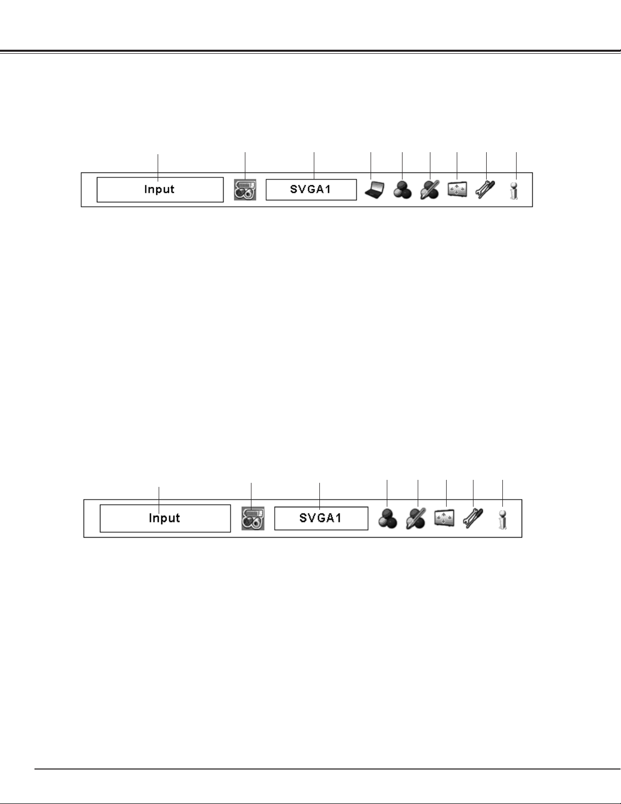
For detailed functions of each menu, see “Menu Tree” on pages 69-71.
For Computer Source
q w oiuytre
qGuide Window
Show the selected Menu of the On-Screen Menu.
w
Input Menu
Used to select an input source Computer or Video (pp. 31-
33).
e
PC System Menu
Used to select computer system (p. 34).
r
PC Adjust Menu
Used to adjust the parameters to match with the input signal
format (pp. 35-37).
tImage Select Menu
Used to select an image level among Standard, Real, and
Image 1–10(p. 38).
For Video Source
q
w
yImage Adjust Menu
Used to adjust the computer image. [Contrast/ Brightness/
Color management/Auto picture control/Color temp./White
balance (R/G/B)/Offset (R/G/B)/Sharpness/ Gamma/Reset/
Store] (pp. 45-47).
uScreen Menu
Used to adjust the size of the image. [Normal/True/Wide/
Full screen/Custom/Keystone/Ceiling/Rear/Reset/Digital
zoom +/–] (pp.39-40).
iSetting Menu
Used to set the projector’s operating configurations
(pp. 48-56).
oInformation Menu
Display the input source information(p. 28).
e
iuytr
26
qGuide Window
Show the selected Menu of the On-Screen Menu.
w
Input Menu
Used to select an input source Computer or Video (pp. 31-
33).
eAV System Menu
Used to select the system of selected video source (p. 41).
rImage Select Menu
Used to select an image level among Standard, Cinema, and
Image 1–10 (p. 42).
tImage Adjust Menu
Used to adjust the picture image. [Contrast/Brightness/
Color/Tint/Color management/ Auto picture control/Color
temp./White balance (R/G/B)/ Offset (R/G/B)/Sharpness/
Gamma/Noise reduction/Progressive/Reset/Store]
(pp. 45-47)
yScreen Menu
Used to adjust the size of the image. [Normal/Wide/
Custom/Keystone/Ceiling/Rear/Reset] (pp. 43-44).
uSetting Menu
Used to set the projector’s operating configurations
(pp. 48-56).
iInformation Menu
Display the input source information(p. 28).
 Loading...