

Page 1

PARTS LIST
Following parts are contained in the packing.
· LENS 1 piece
· LENS MOUNTING SCREWS 6 screws (2 for spare)
· DRIVER 1 piece
· LIGHT-BLOCK SHEET 1 sheet
· LENS COVER 1 set
NOTES ON LENS REPLACEMENT
LENS REPLACEMENT PROCEDURE
LCD PROJECTOR LENS
MODEL NO. PLC-LNS07
PLC-LNS08
Lens replacement should be performed by the qualified service personnel.
It should be followed by this procedure precisely.
Before attempt to replace the lens, confirm the model number (both the LCD
projector and the lens) and use the proper lens.
If you have any questions, contact to the dealers.
Following checks and confirmations should be taken for safety.
Check the following things by the time of the cabinet cover installation after
the lens replacement.
1. Confirm the proper wiring and the wires are fixed properly.
2. Confirm the each connector is connected properly.
3.Wiring must not be tangled in the gear of the lens motor or the other
mechanical part.
4.There is no missing part, or no loosing mounting par t.
1AA6P1P1732-- (ICKV)
● The focus and zoom of this lens can’t be adjusted by controls on main cabinet or the remote control unit.
Page 2
LENS REPLACEMENT PROCEDURE
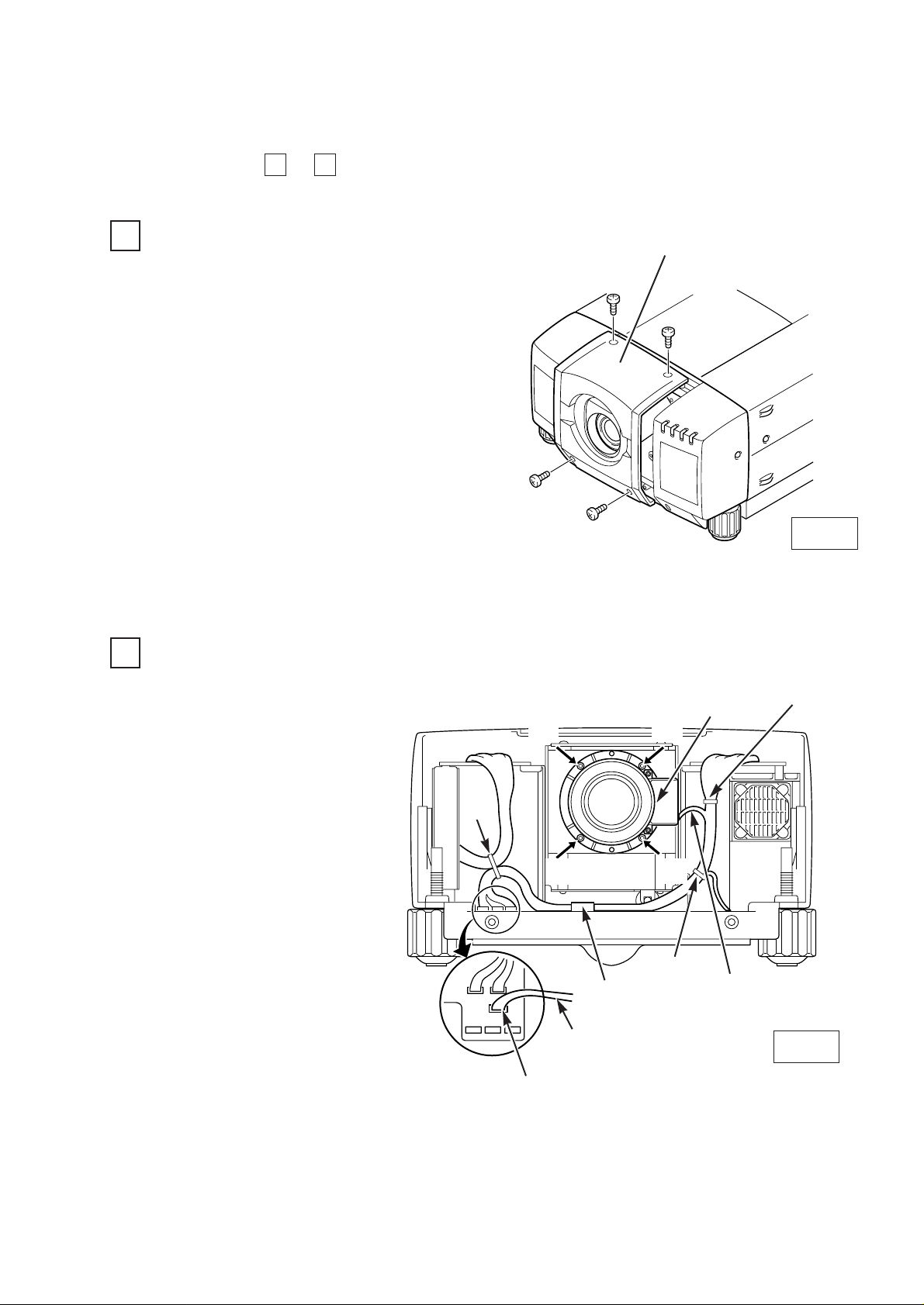
REMOVE THE LENS COVER. (See figure-1.)
1
1. Turn on the LCD projector.
2. Adjust the lens shift, so that lens is set in
the center.
3. Turn off the LCD projector and disconnect
the power cord from the AC outlet.
4. Remove 4 screws of the lens cover and
remove the lens cover.
REMOVE THE LENS. (See figure-2.)
2
1. Remove the connector
“K16B” of the circuit board.
2. Loosen the A, B wire bands,
wire holder and remove the
lens motor lead.
After removal of the lens
motor lead, fasten it by placing it back into position.
3. Remove scre ws D(4 scre ws)
which fastens the lens and
remove the lens.
LENS
MOT OR LEAD
CONNECTOR “ K16B “
(D)
(D)
(D)
(D)
B
A
C
LENS MOT OR
Fig-2
This part wiring should
not be tightened.
❋Figure shown inside of the cabinet.
Fig-1
LENS COVER
1 5
Perform the steps to for lens replacement.
WIRE HOLDER
Page 3

MOUNT THE LENS COVER. (See figure-5)
INSTALL THE LENS.(See figure-3)
Remove protective caps(front and
back) on the lens.
Mount the lens on mounting bracket of
the main cabinet with 4 screws.
Use the screws included with the lens.
Use the driver included with the lens
to fasten the screws.
3
1.
2.
A
INSTALL THE LIGHT-BLOCK SHEET. (See figure-4)
When this projector permanently install in the
structure, slide the picture, obtain correct
focus, then lock the lens by Focus Lens Lock
screw at this step.
In case unfixing the focus lens, remove the
screw.
4
Install the light-block sheet around the lens as shown in Figure.
Insert the upper par t lens cover and
fix them with screws A (4 screws).
Insert the lower part lens cover and
fix them with screws B.(2 screws).
5
1.
2.
LENS MOUNTING BRACKET
ATTACHED DRIVER
FOCUS LENS LOCK SCREW
UPPER LENS COVER
LOWER LENS COVER
A
B
Fig-3
Fig-4
Fig-5
(After using, save it for latter use.)
When in install the both upper and lower lens
covers, install the light-block sheet so that it
should be placed in the guide slot of the lens
cover. If the installation of the light-block
sheet is incorrect, there will be the space
between lens and the lens cover, so that it will
be the cause of leakage of light or the dust
entering at the main cabinet.
LIGHT-BLOCK SHEET
Set the light-block sheet, so
that the large rounder side is
set over the lens.
Page 4

documentation manual, user maintenance, brochure, user reference, pdf manual
This file has been downloaded from:
User Manual and User Guide for many equipments like mobile phones, photo cameras, monther board, monitors, software, tv, dvd, and othes..
Manual users, user manuals, user guide manual, owners manual, instruction manual, manual owner, manual owner's, manual guide,
manual operation, operating manual, user's manual, operating instructions, manual operators, manual operator, manual product,
 Loading...