

Page 1
INSTRUCTION MANUAL
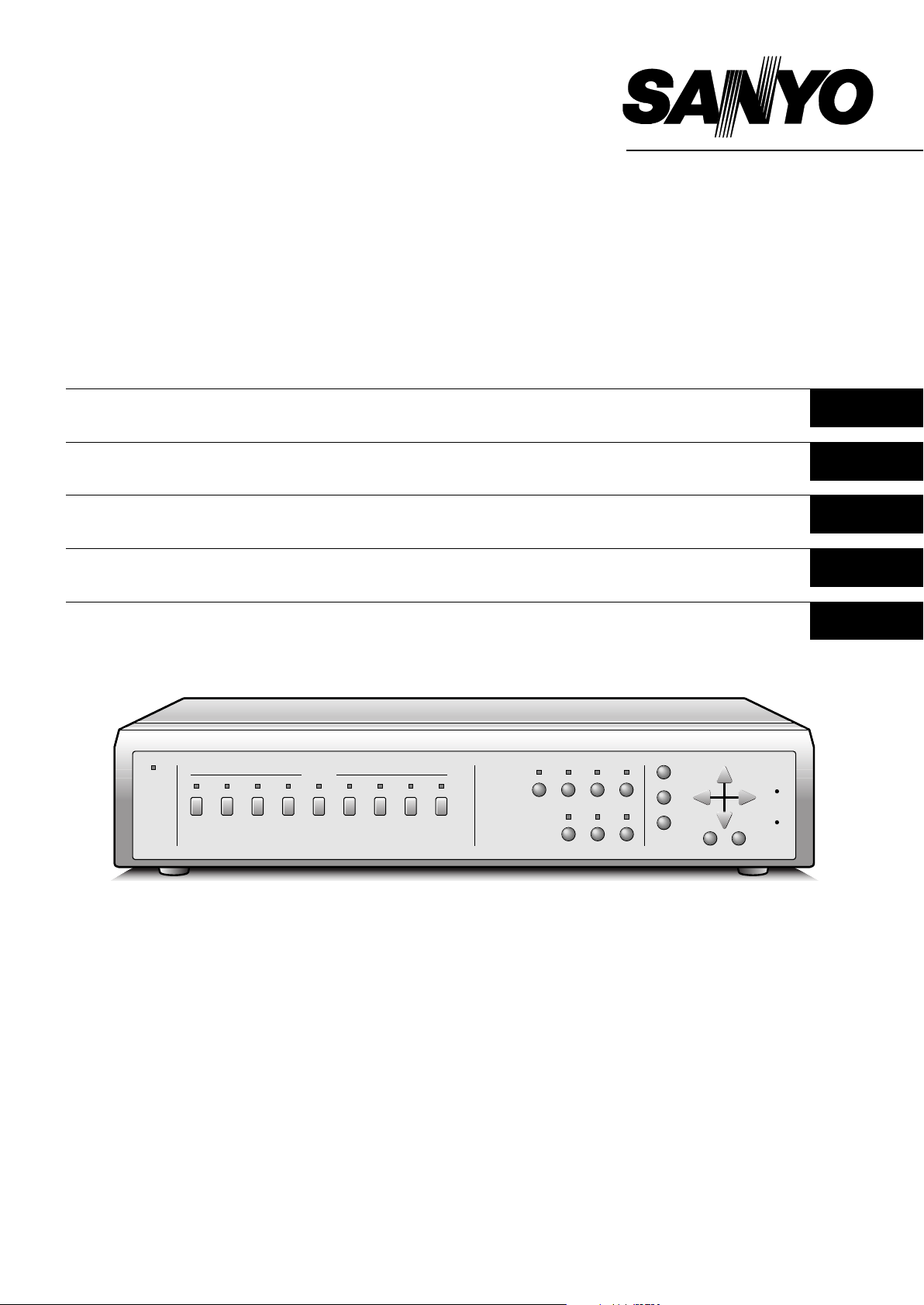
MPX-MS92P
B/W Multiplexer
Schwarzwe iß Mu l tiplexer
Multiplexeur N o ir et B lanc
Blanco y negro Mu ltiplexor
Multi distributore in bianco e nero
English GB
Deutsch D
Français F
Español E
Italiano I
About this manual
Before install ing and using th is unit, please r ead this manual
carefully. Be sure to keep it handy for later reference.
Über diese Anleitung
Lesen Sie bitte diese Bedienungsanleitung vor der Installation
und der Verw endung des Gerätes sorgfältig durch. Bew ahren
Sie die Anleit ung zum späteren Nachschlagen a uf.
À propos de ce manuel
Avant d’installer et d’utiliser cet appareil, veuillez lire ce manuel
attentivement. Assurez-vous de le garder à portée de la main
pour référence ultérieure.
Acerca de este manual
Antes de instalar y usar este apa rato, lea detenidamente e ste
manual. Asegúrese de guardarlo a mano para futuras
referencias.
Nota su questo manuale
Leggere attentamente questo manuale prima di passare
all’installazione ed all’uso di questo apparecchio.
Page 2

PRECAUTION
WARNING: TO REDUCE THE RISK OF FIRE OR
ELECTRIC SHOCK, DO NOT EXPOSE THIS
APPLIANCE TO RAIN OR OTHER MOISTURE.
To avoid electrical shock, do not open the cabinet.
Refer servicing to qualified personnel only.
If the power supply cord (AC power cord) of this
appliance is damaged, it must be replaced. Return to a
SANYO Authorised Service Centre for replacement of
the cord.
Location
For safe operation and satisfactory performance of your
multiplexer, keep the following in mind when selecting a place
for its installation:
Shield it from direct sunlight and keep it away from sources of
•
intense heat.
Avoid dusty or humid places.
•
Avoid places with insufficient ventilation for proper heat
•
dissipation. Do not block the ventilation holes at the top and
bottom of the multiplexer. Do not place the unit on a carpet
because this will block the ventilation holes.
Install the multiplexer in a horizontal position only.
•
Avoid locations subject to strong vibrations.
•
Avoid moving the multiplexer between cold and hot locations.
•
Do not place the multiplexer directly on top of a monitor TV,
•
as this may cause playback or recording problems.
Avoiding Electrical Shock and Fire
Do not handle the power cord with wet hands.
•
Do not pull on the power cord when disconnecting it from an
•
AC wall outlet. Grasp it by the plug.
If any liquid is spilled on the multiplexer, unplug the power
•
cord immediately and have the unit inspected at a
factory-authorised service centre.
Do not place anything directly on top of this multiplexer.
•
SERVICE
This unit is a precision instruments and if treated with care, will
provide years of satisfactory performance. However, in the event
of a problem, the owner is advised not to attempt to make
repairs or open the cabinet. Servicing should always be referred
to your dealer or Sanyo Authorized Service Centre.
CAUTION
Danger of explosion if battery is incorrectly replaced.
Replace only with the same or equivalent type recommended
by the manufacturer.
Discard used batteries according to the manufacture’s
instructions.
English 1
Page 3

CONTENTS
FEATURES
PARTS NAMES . . . . . . . . . . . . . . . . . . . . . . . . . . . . . . . 3
FRONT PANEL . . . . . . . . . . . . . . . . . . . . . . . . . . . . . . . . . . . 3
REAR PANEL . . . . . . . . . . . . . . . . . . . . . . . . . . . . . . . . . . . . 4
CONNECTION . . . . . . . . . . . . . . . . . . . . . . . . . . . . . . . . 5
BASIC CONNECTIONS . . . . . . . . . . . . . . . . . . . . . . . . . . . . 5
CONNECTIONS TO THE ALARM IN AND
RS232C/RS485 TERMINALS . . . . . . . . . . . . . . . . . . . . . . . . 6
REMOTE CONTROLLER CIRCUIT CONNECTIONS . . . . . 7
BASIC OPERATIONS . . . . . . . . . . . . . . . . . . . . . . . . . . 8
FIELD SWITCHER AND MULTI-VIEWER FUNCTIONS . . . 8
MODE SWITCHING . . . . . . . . . . . . . . . . . . . . . . . . . . . . . . . . 9
SECURITY LOCK FUNCTION . . . . . . . . . . . . . . . . . . . . . . 10
SETTINGS BACKUP FUNCTION . . . . . . . . . . . . . . . . . . . . 10
RESET FUNCTION . . . . . . . . . . . . . . . . . . . . . . . . . . . . . . . 10
FIELD SWITCHER MODE . . . . . . . . . . . . . . . . . . . . . . 11
LIVE PICTURE MODE . . . . . . . . . . . . . . . . . . . . . . . . . . . . 11
FULL SCREEN OPERATIONS . . . . . . . . . . . . . . . . . . . 11
ALARM OPERATION . . . . . . . . . . . . . . . . . . . . . . . . . . . 11
VCR PLAYBACK MODE . . . . . . . . . . . . . . . . . . . . . . . . . . . 12
VCR PLAYBACK MODE OPERATIONS STEPS
ON MONITOR . . . . . . . . . . . . . . . . . . . . . . . . . . . . . . . . . 12
FULL SCREEN OPERATIONS . . . . . . . . . . . . . . . . . . . 13
4 DIVISIONS SPLIT SCREEN OPERATIONS . . . . . . . . 15
MULTI-DISPLAY SCREEN OPERATIONS . . . . . . . . . . 15
ALARM OPERATION . . . . . . . . . . . . . . . . . . . . . . . . . . . 15
MULTI-VIEWER MODE . . . . . . . . . . . . . . . . . . . . . . . . 16
LIVE PICTURE MODE . . . . . . . . . . . . . . . . . . . . . . . . . . . . 16
LIVE PICTURE MODE OPERATIONS STEPS ON
MONITOR . . . . . . . . . . . . . . . . . . . . . . . . . . . . . . . . . . . . 16
FULL SCREEN OPERATIONS . . . . . . . . . . . . . . . . . . . 17
4 DIVISIONS SPLIT SCREEN OPERATIONS . . . . . . . . 19
MULTI-DISPLAY SCREEN OPERATIONS . . . . . . . . . . 19
ALARM OPERATIONS . . . . . . . . . . . . . . . . . . . . . . . . . 20
VCR PLAYBACK MODE . . . . . . . . . . . . . . . . . . . . . . . . . . . 21
VCR PLAYBACK MODE OPERATIONS STEPS
ON MONITOR . . . . . . . . . . . . . . . . . . . . . . . . . . . . . . . . . 21
MENU SETTING MODE . . . . . . . . . . . . . . . . . . . . . . . . 22
MENUS DISPLAYS . . . . . . . . . . . . . . . . . . . . . . . . . . . . . . . 22
LANGUAGE SETTING . . . . . . . . . . . . . . . . . . . . . . . . . . . . 23
CLOCK AND SUMMER TIME SETTING . . . . . . . . . . . . . . 24
VCR SETTING AND EXTERNAL CONTROL
COMMUNICATION SPEED SETTING . . . . . . . . . . . . . . . . 26
ALARM AND SENSOR SETTING . . . . . . . . . . . . . . . . . . . 28
ACTIVE RECORDING AND VIDEO LOSS SETTING . . . . 30
MONITOR SETTINGS . . . . . . . . . . . . . . . . . . . . . . . . . . . . . 32
CAMERA SETTING . . . . . . . . . . . . . . . . . . . . . . . . . . . . . . . 33
SETTING EACH CAMERA DISPLAY POSITION IN
SPL I T SCREEN DISPLAY MODE . . . . . . . . . . . . . . . . . . . . 40
CLOCK AND TITLE DISPLAY SETTINGS . . . . . . . . . . . . 41
ALARM DATA DISPLAY . . . . . . . . . . . . . . . . . . . . . . . . . . 42
ALARMS OPERATIONS . . . . . . . . . . . . . . . . . . . . . . . 43
INTERFACE SPECIFICATIONS . . . . . . . . . . . . . . . . . 45
SPECIFICATIONS . . . . . . . . . . . . . . . . . . . . . . . . . . . . 50
This unit can display live camera images in full screen mode or
in a split screen (4 or 9 divisions). Recorded pictures can also be
displayed in a split screen.
The field switcher function can, during recording, display the
•
images full screen or full screen sequentially.
The multi-viewer function can, during live images mode,
•
display the images in a split screen and record the images as
displayed.
High-speed switching (up to single field switching)
•
The following operations are possible at each camera
•
according to the timer settings:
Programmed recording of certain or all cameras only can be
•
done according to the day or night periods.
Different alarm durations of certain or all cameras can be set
•
according to the day or night periods.
Live or recorded pictures of certain or all cameras can be
•
masked so they are not visible according to the day or night
periods.
Automatic switching delay can be set for each camera
•
according to the day or night periods.
Video sensor points areas can be set for each camera.
•
Trigger can start alarm recording operations in priority.
If the video signal is interrupted at any of the cameras, the
•
frozen image just previous to the interruption or test chart can
be displayed (selectable for each camera).
The unit can be controlled by computer through the RS232C
•
connection.
A system controller (sold separately) can be used through the
•
RS485 (RJ-11) connection.
Up to 100 alarm entries can be displayed on-screen.
•
ACCESSORIES
1 Power cord x1
2 Fixer, Power cord tie x1
2
To mount this unit onto a rack, please use the rack mount
hardware sold separately.
2 English
Page 4

PARTS NAMES
FRONT PANEL
12 3456FIG
SEQUENCE
MENU
NEXT
EXIT
DISPLAY
ALL
RESET
MENU
RESET
+
–
K
L
POWER
SELECT
1 2 3 4 5 6 7 8 9
QUAD MULTI LIVE VCR
ZOOM STILL
JH987
This unit is not equipped with a power switch. The power is turned on/off when the supplied power cord is connected/disconnected at
the power source.
1 POWER indicator
2 Camera SELECT buttons and camera indicators
Use these buttons to select the picture from the
corresponding camera. Also, when in still image, sequential
display, 4 divisions split screen or multi-display screen
modes, press one of these buttons to return to the normal
picture full screen display of the corresponding camera.
3 QUAD button and indicator
In sequential display, full screen display or multi-display
screen modes, press this button to switch to 4 divisions
display screen. Press repeatedly to switch to subsequent 4
divisions screens.
4 MULTI button and indicator
5 LIVE button and indicator
Press this button to select the live input mode.
6 VCR button and indicator
Press this button to select the VCR playback input mode.
8 STILL button and indicator
In full screen display mode, press this button to freeze the
displayed image. Press the button one more time to cancel.
9 SEQUENCE button and indicator
In 4 divisions split screen or full screen display modes,
press this button for an automatic sequential full or 4
division split screen display of the pictures.
F MENU button (see page 9)
Press this button to display the menus. Press repeatedly to
select the different menus in order.
G NEXT button
H EXIT/DISPLAY button
I j, l, c, d button
J +, – button
K ALL RESET button (see page 10)
L MENU RESET button (see page 10)
7 ZOOM button and indicator
In full screen display mode, press this button for a 2x
zoomed in image. Press the button one more time to cancel.
About the cooling fan
In order to keep the unit internal temperature low, a fan is
provided on the side of the unit. If the fan does not operate
properly, the POWER indicator will flash to indicate a problem.
Unplug the unit from the power supply and check to make sure
nothing is obstructing the fan. If after the power is restored to the
unit, the POWER indicator still flashes, do not use the unit and
consult your dealer.
English 3
Page 5
PARTS NAMES
REAR PANEL
9
FG
IN
CAMERA
1
123C456789
2
OUT
VCR
IN
OUT
345 6 7 8
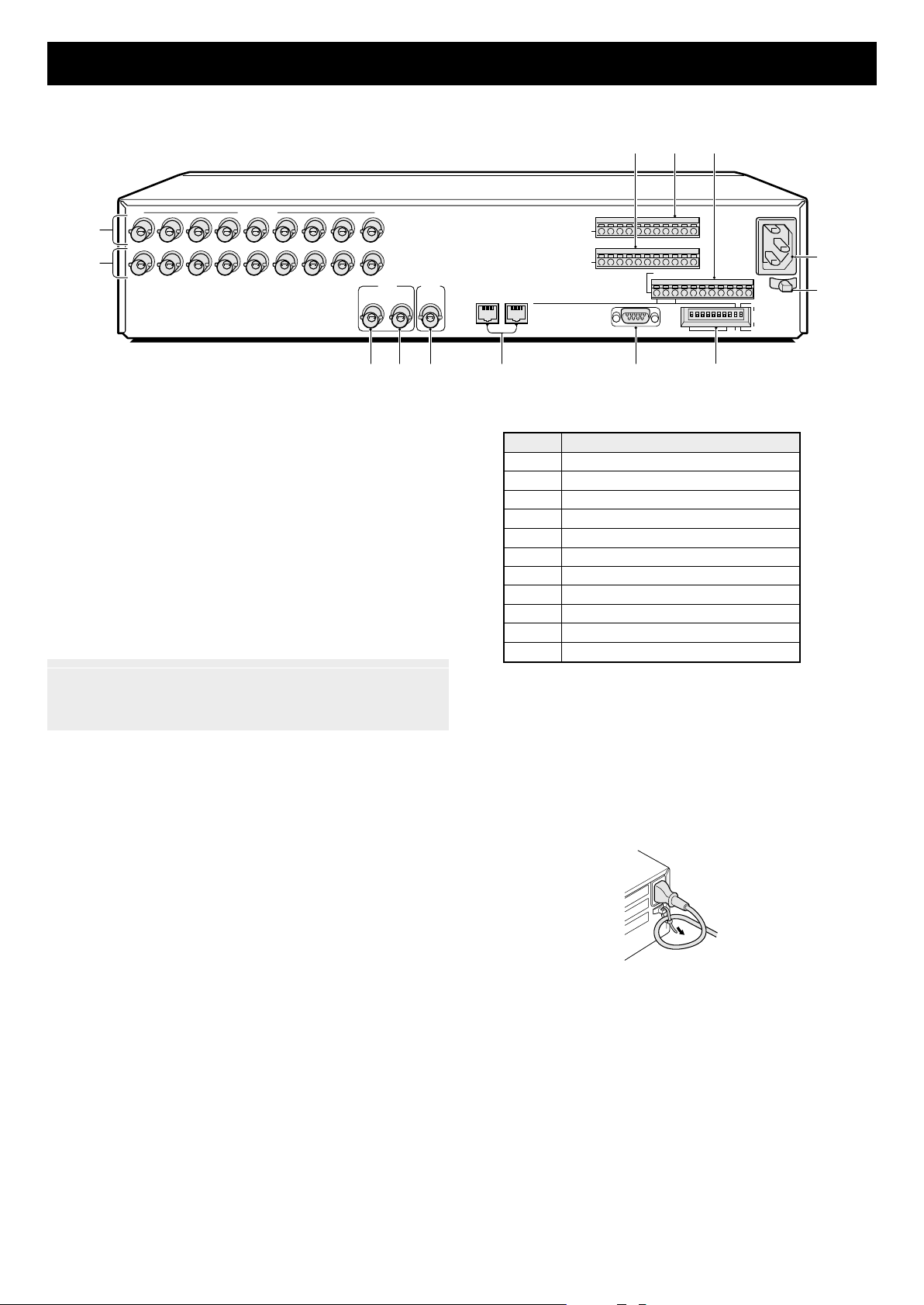
1 CAMERA IN terminals (1 – 9)
2 CAMERA OUT terminals (1 – 9)
Each camera signal is output directly at these terminals.
3 VCR IN (Video cassette recorder input) terminal
4 VCR OUT (Video cassette recorder output) terminal
5 MONITOR (Monitor output) terminal
6 RS-485 control ports
RS485 A: RJ-11 A terminal
Used for connection with a modular cable.
RS485 B: RJ-11 B terminal
Used for connection with a modular cable.
Note:•Do not connect to a phone line.
Only up to two RS-485 control ports can be used.
•
Do not use all of the RS-485 control ports.
•
7 RS-232C (RS232C) terminal
To control this unit using a personal computer, connect the
computer serial terminal to this terminal using a 9-pin
D-SUB cable (sold separately).
8 Interface setting DIP switches (ADDRESS, RS-232C,
RS-485, TERMINATE)
9 SENSOR ALARM OUT terminals (1 – 9)
MONITOR
ALARM
IN
RS485
A B
SENSOR ALARM
12345678
OUT
CONTROL
RS232C
NC
9
CABCALC
485
ON
123456789
ADDRESS
R1 R2CSW
232
C
ON
TERMI
10
NATE
OFF
G CONTROL terminal
Pin Signal
C Ground
A RS485 terminal *
B RS485 terminal *
C Common
AL Alarm output (DC 5V)
C Common
R1 Remote input 1
R2 Remote input 2
C Common
SW Switching input (DC 5V)
C Common
* Used for connection with a twisted-pair cable.
H AC Power socket (AC IN~)
Insert the power cord female plug firmly into this socket.
When the other plug of the power cord is connected to a live
power source, the POWER indicator on the front panel will
light.
I Power cord holder
Using the supplied tie, attach the power cord to the holder
as illustrated.
H
I
F ALARM IN (Alarm signal input) terminals
The alarm triggers input to the unit are output at the AL pin
of the CONTROL terminal.
4 English
Page 6
CONNECTION
Before making any connection, make sure all the devices are turned off.
Before making the connections, please refer to the instruction manual accompanying each device. If the devices are not connected
properly, that may cause a fire and/or damages.
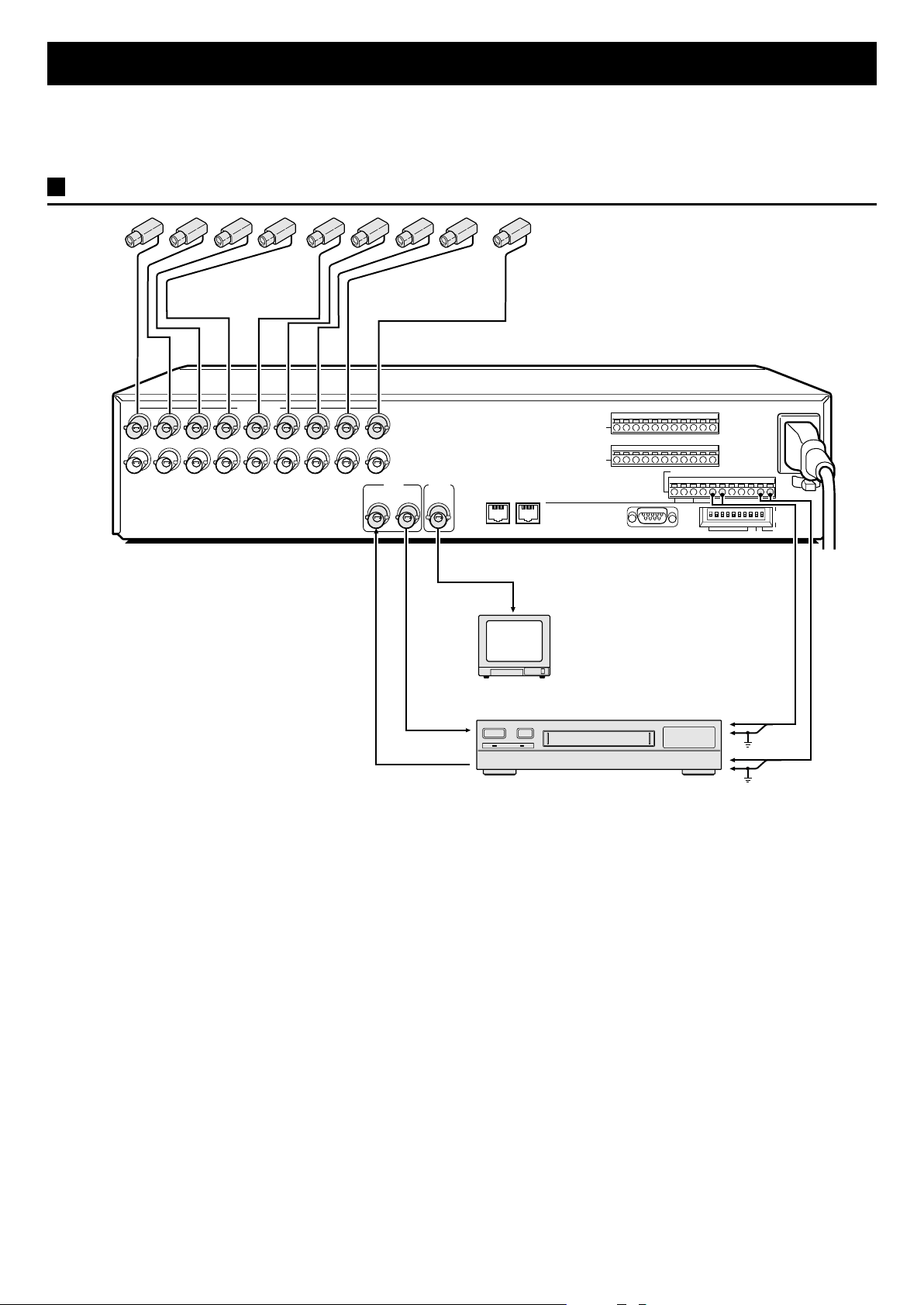
BASIC CONNECTIONS
IN
123C456789
OUT
CAMERA
NOTE:
The camera signal input at each CAMERA IN
terminal is throughput at the corresponding
CAMERA OUT terminal. The CAMERA IN
terminals are automatically terminated at 75 Ω.
• When no connection is made to the CAMERA
OUT terminal, the CAMERA IN terminal 75 Ω
termination is made automatically.
• When a connection is made to the CAMERA
OUT terminal, the CAMERA IN terminal
termination is open, you must therefore make
sure the CAMERA OUT side is terminated.
• With model MPX-MS92P, use black and white
cameras only. If color cameras are used, that
may cause image beat, etc.
VCR
IN OUT
MONITOR
RS485
A B
Video input
terminal
Monitor (sold separately)
Timelapse VCR (sold separately)
ALARM
SENSOR ALARM
OUT
IN
123456789
CONTROL
RS232C
NC
CABCALC
485
ON
12345678910
ADDRESS
R1 R2CSW
C
ON
TERMI
NATE
OFF
232
ALARM input
terminal
Ground
Ground
Switching output
terminal
English 5
Page 7
CONNECTION
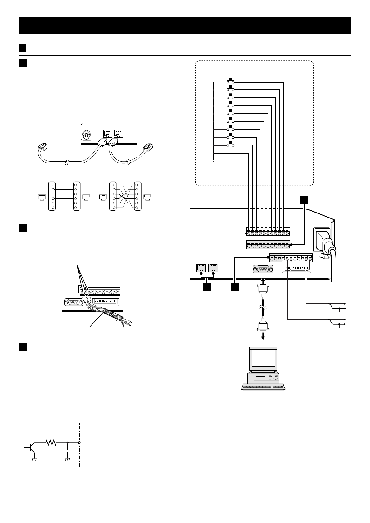
CONNECTIONS TO THE ALARM IN AND RS232C/RS485 TERMINALS
A RS485 (RJ-11) terminal connection
Make the connection to the RS485 control terminal using a
modular cable (sold separately).
If using a straight type cable, connect it between the A
•
terminals, or between the B terminals (see illustration below).
If using a crossed type cable, connect it from the A terminal
•
to the B terminal, or from the B terminal to the A terminal (see
illustration below).
MONITOR
To terminal A To terminal A
Straight-type cable Cross-type cable
Not used
1
Not used
2
16
3
4
Not used
5
Not used
6
1
2
16 16 16
3
4
5
6
Straight type
RS485
A B
1
2
3
4
5
6
Cross type
Not used
Not used
Not used
Not used
1
2
3
4
5
6
B Using the push-lock terminals
Make the connections to pins A, B, C (Ground) of the
CONTROL terminal using a twisted-pair cable (sold separately).
Then, connect signal A to A, and signal B to B.
Push in to insert cable
Common
RS485
A B
External alarm sensors
(door bell, interphone, etc.)
ALARM
IN
123456789
C
SENSOR ALARM
OUT
CONTROL
NC
CABCALC
C
R1 R2CSW
C
CABCALC
RS232C
R1 R2CSW
C
To B signal
Twisted-pair cable
To A signal
Ground
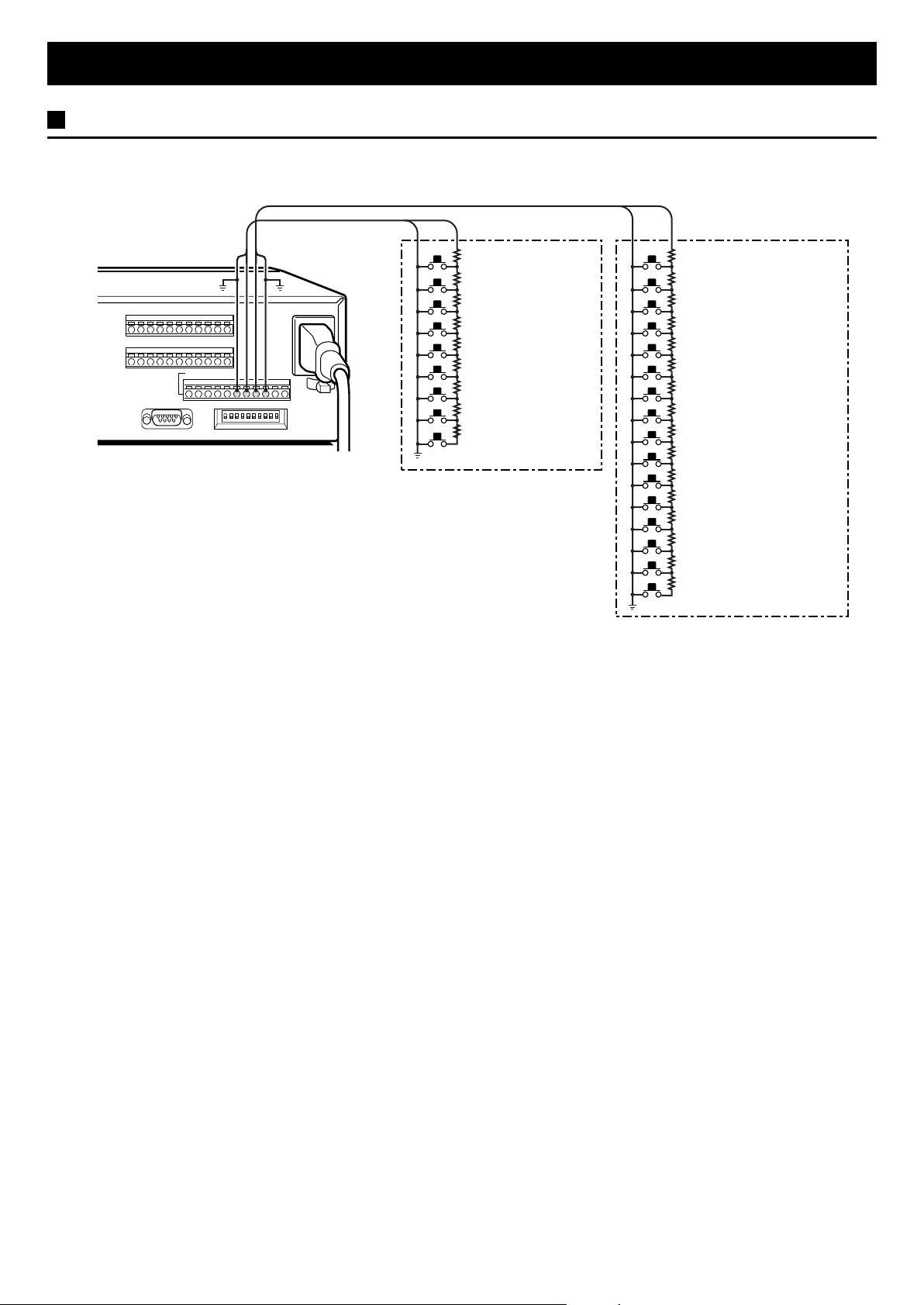
C SENSOR ALARM OUT terminals
When the unit internal video sensor send a trigger, it will be
output at the SENSOR ALARM OUT terminals. By connecting
indicator lamps switching circuits to theses connectors (Fig. 1),
an indication can be generated when the video sensors send a
trigger.
For example, the video sensor alarm indicator lamps could be
laid out on a factory floor plan to give accurate indication of
trigger location. The terminals are normally open (NO). A trigger
at the video sensor for one of the cameras, will switch the signal
to LOW.
Fig. 1
1K
Rating values for each connector (at 25˚C)
• Maximum current : 25 mA
• Maximum voltage : 25 V
• Maximum power : 40 mW
RS232C
A
B
9-pin D-SUB cable
(sold separately)
Computer
Connect a 9-pin D-SUB cable (sold
separately) from the RS232C terminal
on the rear panel to the computer
serial connector.
Switching output
terminal
Common
Common
Alarm input
terminal
6 English
Page 8
CONNECTION
REMOTE CONTROLLER CIRCUIT CONNECTIONS
Use the layout below to make a remote controller and make the connections to the remote input pins (R1, R2) of the
CONTROL terminal as indicated. This will permit remote controlled operation of this unit. (make contact LOW input)
R1 R2
CONTROL
CABCALC
R1 R2CSW
220Ω
SW 1
SW 2
SW 3
SW 4
SW 5
SW 6
SW 7
SW 8
SW 9
: Camera 1
: Camera 2
: Camera 3
: Camera 4
: Camera 5
: Camera 6
: Camera 7
: Camera 8
: Camera 9
220Ω
300Ω
360Ω
470Ω
C
680Ω
820Ω
1.2kΩ
1.8kΩ
SW: switch
220Ω
220Ω
300Ω
360Ω
470Ω
680Ω
820Ω
1.2kΩ
1.8kΩ
2.2kΩ
3.3kΩ
4.7kΩ
7.5kΩ
13kΩ
27kΩ
68kΩ
SW 10
: Menu selection
SW 11
: VCR playback
SW 12
: Live picture
SW 13
: MULTI
SW 14
: Not used
SW 15
: Camera sequential
display
SW 16
: Zoom
SW 17
: Still image
SW 18
: Not used
SW 19
: 4 divisions split screen
SW 20
: NEXT
SW 21
: EXIT/DISPLAY
SW 22
: +
SW 23
: –
SW 24
: 3
: 2
SW 25
English 7
Page 9
BASIC OPERATIONS
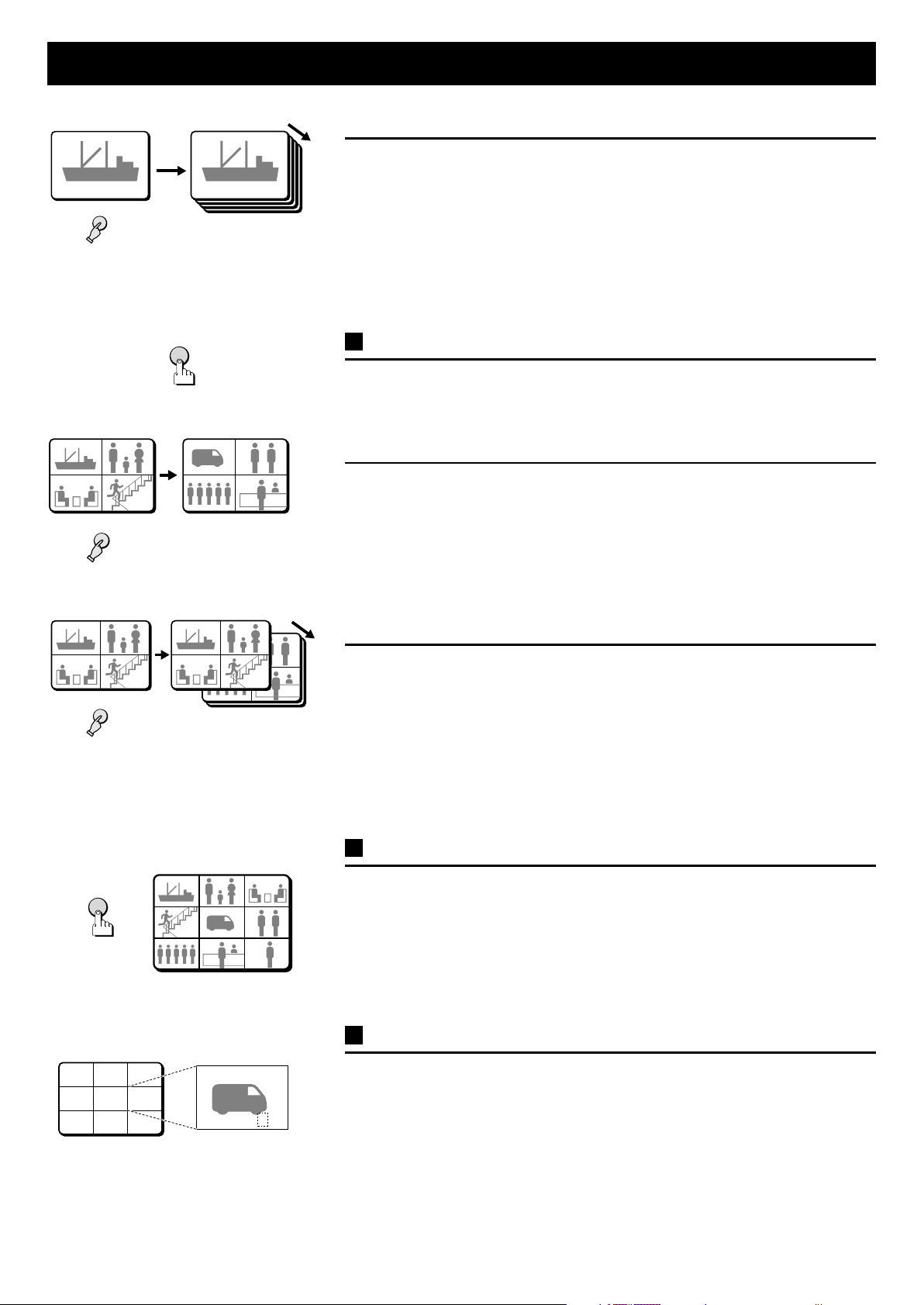
FIELD SWITCHER AND MULTI-VIEWER FUNCTIONS
This unit can operate in field switcher (full screen) mode and multi-viewer (split screen) mode. When the power is turned on, the
default operating mode is field switcher (full screen) mode.
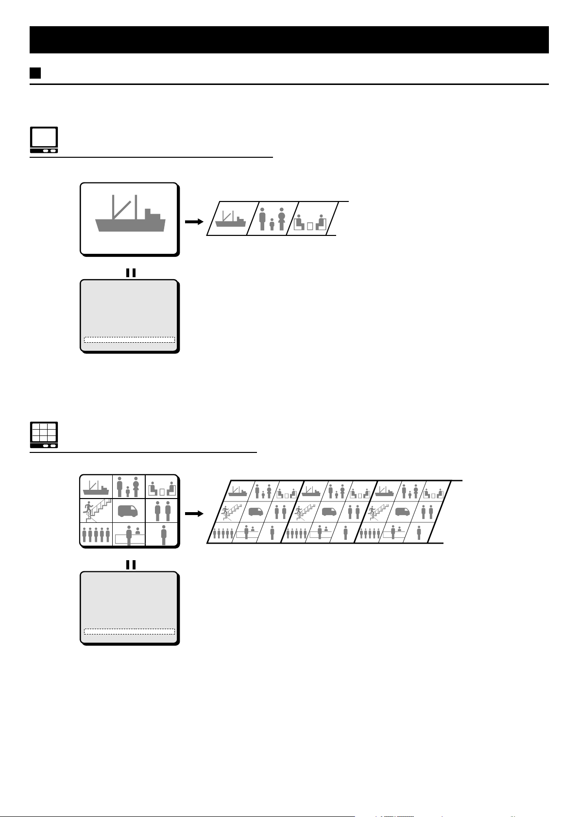
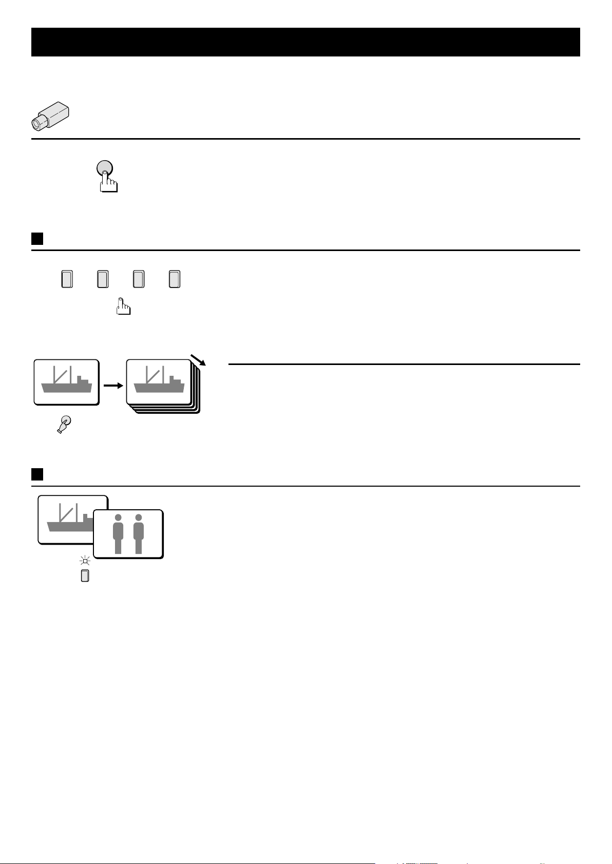
Field Switcher Mode (MULTI MODE: OFF)
To record multiple live images feeds sequentially in full screen (field) mode.
01 02 0301 02 03
0101
(Monitor)
(MONITOR SET)
MON. SEQ.TIMER 1 S
QUAD SEQ.TIMER 1 S
MON. SEQ.MODE MODE1
MON.MASK LIVE ON
MON.MASK VCR ON
MULTI MODE OFF
(Sent to the VCR for recording)
(Menu setting screen)
☞ Setting the desired mode
In the (MONITOR SET) menu set MULTI MODE to ON (for multi-viewer) or OFF (for field switcher) as desired (see page 32).
Multi-viewer Mode (MULTI MODE: ON)
To record live images in full screen or split screen (4 or 9 divisions).
0101 020202 030303
0404 050505 060606
0707 080808 090909
(Monitor)
(MONITOR SET)
MON. SEQ.TIMER 1 S
QUAD SEQ.TIMER 1 S
MON. SEQ.MODE MODE1
MON.MASK LIVE ON
MON.MASK VCR ON
MULTI MODE ON
01 02 03
01 02 03
04 05 06
04 05 06
07
07
08 09
08 09
(Sent to the VCR for recording)
01 02 03
01 02 03
04 05 06
04 05 06
07
07
08 09
08 09
01 02 03
01 02 03
04 05 06
04 05 06
07
07
08 09
08 09
(Menu setting screen)
8 English
Page 10
BASIC OPERATIONS
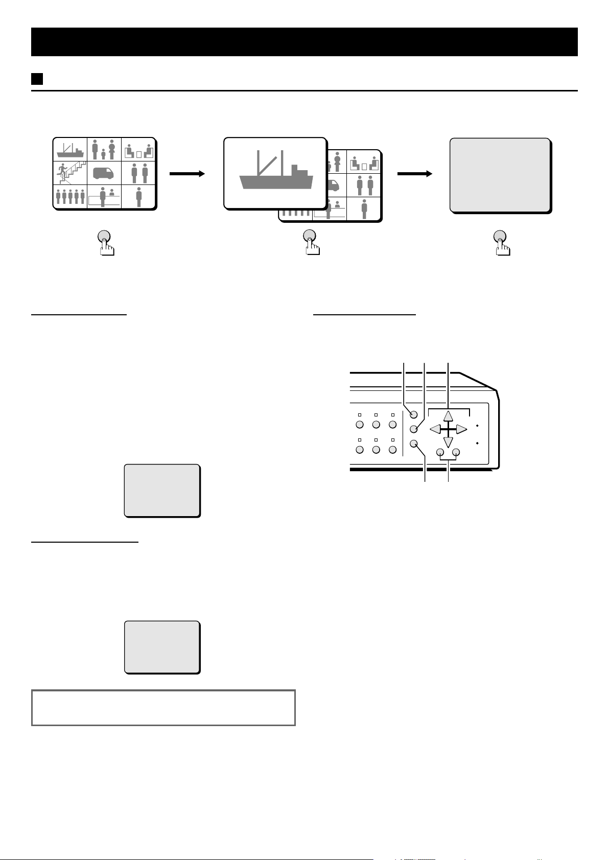
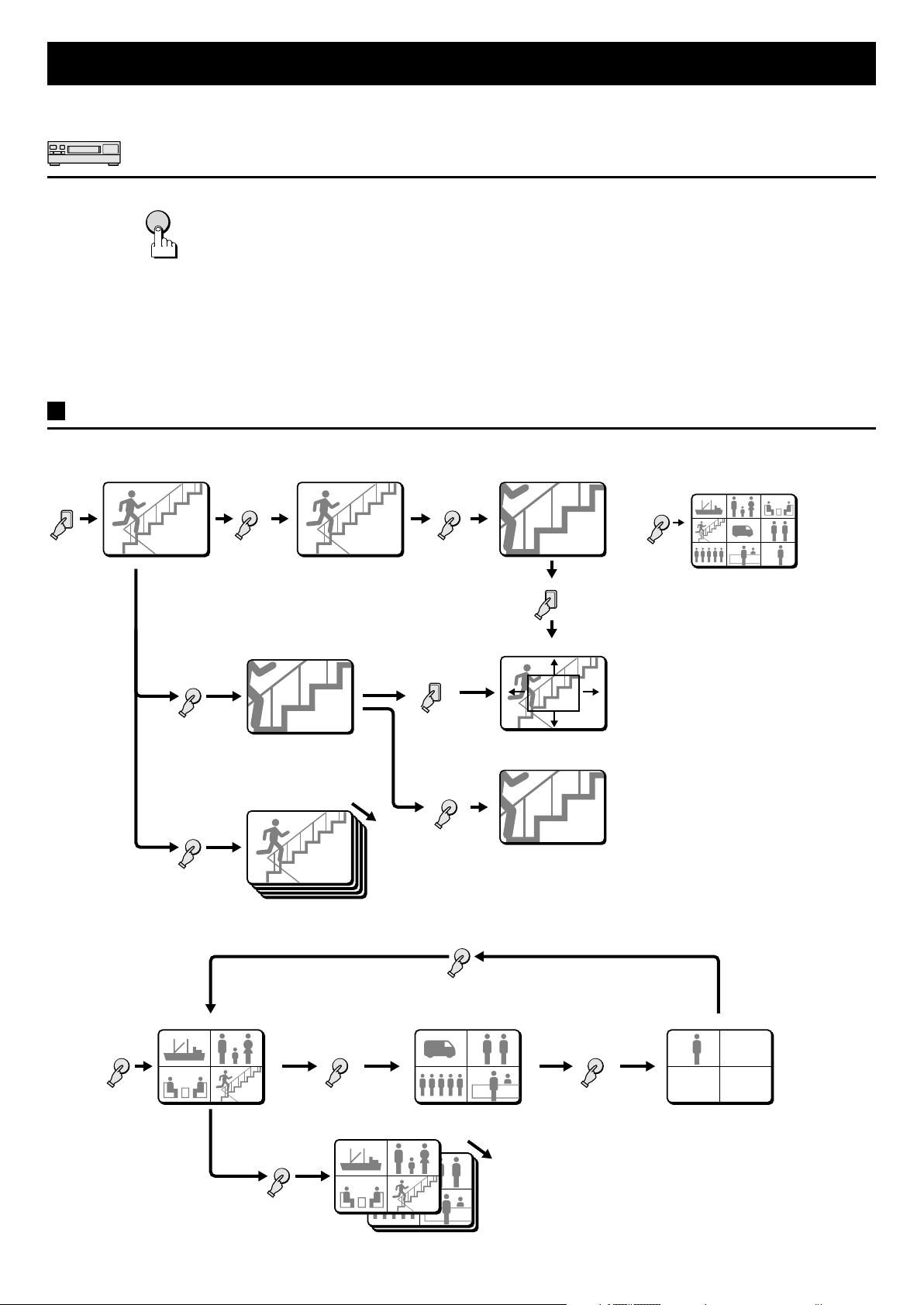
MODE SWITCHING
When the VCR, LIVE or MENU button is pressed the corresponding mode screen is displayed as shown below.
VCR playback mode LIVE picture mode
0101 0202 0303
0101 0202
0404
0707
0505 0606
0808
VCR
0404
or
0101
0707
LIVE
0909
0505 0606
0808
0303
0909
Menu mode
(LANGUAGE/LANG./SPRACHE)
ENGLISH
FRANCAIS
DEUTSCH
MENU
NOTE: When the power is restored after having already used the unit, the unit will restart in the modes selected before the
unit was turned off.
Live Picture Mode (see page 11, 16)
When the LIVE button is pressed, the live (direct) picture from
the cameras connected to the camera input terminals (1 – 9) on
the unit rear panel, will be displayed on monitor.
The image displayed on-screen will depend on the mode set,
Menu Setting Mode (see page 22)
1 Press the MENU button to display the menu.
The buttons used for menu control are indicated below.
3
21
field switcher or multi-viewer mode (see page 8 or 32).
NOTE:
The unit will automatically start in the live picture or VCR
•
playback display mode (9, 4 divisions split screen, full screen
or sequential display) last selected. Therefore, when a mode
is selected, the display mode will remain the same.
If a camera is not connected at one of the input terminals,
•
“NO VIDEO” will be displayed on the monitor screen.
MULTI LIVE VCR
ZOOM STILL
SEQUENCE
MENU
NEXT
EXIT
DISPLAY
–+
RESET
RESET
ALL
MENU
NO VIDEO
VCR Playback Mode (see page 12, 21)
Start playback on the VCR. If the video signal is correctly
recorded, the VCR playback image will be displayed on monitor
when the VCR button is pressed.
NOTE: When playing back a tape not recorded on this unit or a
tape recorded in multi-viewer mode (MULTI MODE set
to ON), “NO ID” will be displayed on-screen.
NO ID
NOTE: In live picture mode and VCR playback mode there
may be a slight vertical roll of the picture.
5
4
2 NEXT button
To select a sub-menu (in the (CAMERA SET), (POSITION SET),
(DISPLAY SET) menus) in order to set the title position, etc.
Press the NEXT button to switch between the menu and the
sub-menu.
3 j, l, c, d buttons...press repeatedly
j button: will move the cursor up.
•
l button: will move the cursor down.
•
c button: will move the cursor towards the right.
•
d button: will move the cursor towards the left.
•
4 EXIT/DISPLAY button (see page 10)
To exit the menu mode and return to live picture mode.
Also, when in live picture mode or VCR playback mode, press
this button to switch the display of the camera title and the clock
display on/off.
5 +, – buttons...press repeatedly
+ button: for forward selection of numbers, letters,
•
– button: for backward selection of numbers, letters,
•
symbols.
symbols.
English 9
Page 11
BASIC OPERATIONS
y
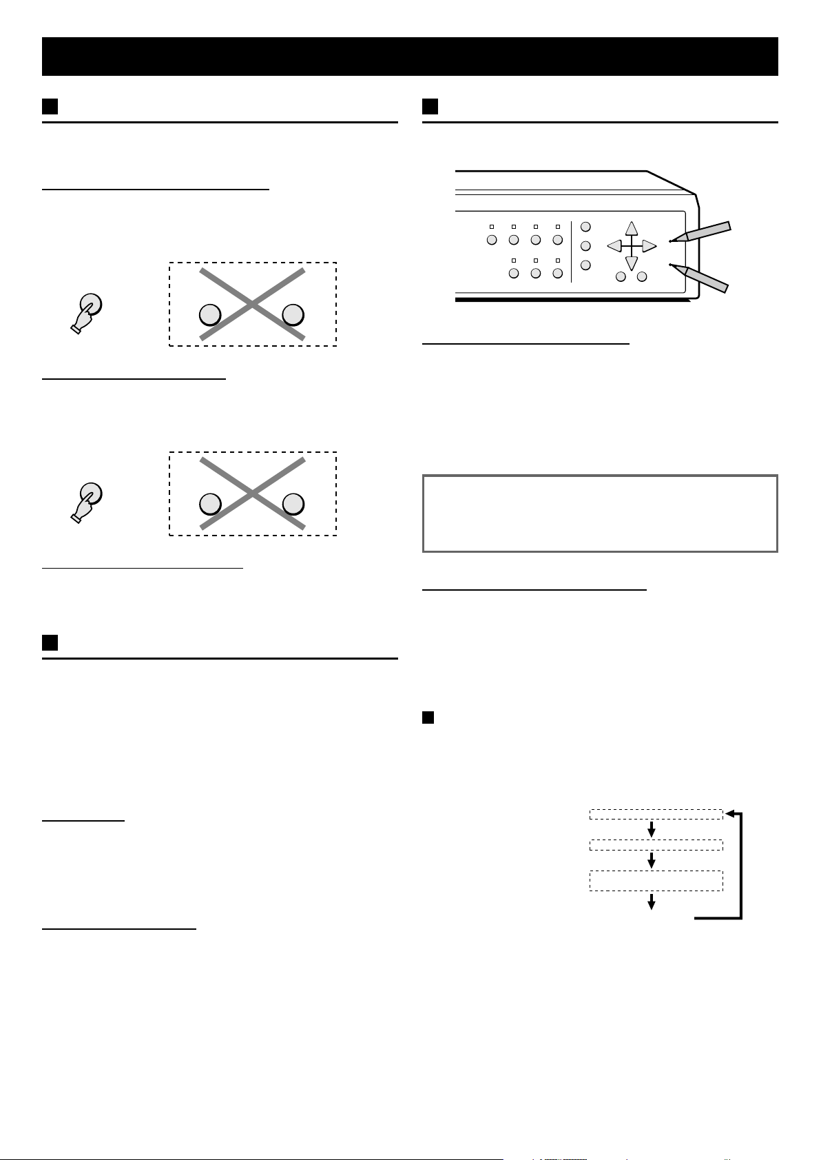
SECURITY LOCK FUNCTION
This function lets you lock the camera live picture mode or VCR
playback mode, so that it cannot be switched to another mode.
Camera Live Picture Mode Lock
Press the LIVE button for about 3 seconds.
A buzzer will be heard, and the VCR and MENU buttons will not
operate if pressed. If buttons are pressed, a buzzer will be heard
and the operation will not be possible.
LIVE
VCR MENU
VCR Playback Mode Lock
Press the VCR button for about 3 seconds.
A buzzer will be heard, and the LIVE and MENU buttons will not
operate if pressed. If buttons are pressed, a buzzer will be heard
and the operation will not be possible.
VCR
LIVE MENU
Canceling the Security Lock
To cancel the security lock, press the same button again for
about 3 seconds. A buzzer will be heard and the mode will be
unlocked.
SETTINGS BACKUP FUNCTION
This unit bottom is equipped with a backup battery (lithium
battery) to maintain the clock settings. When the unit is used
under normal conditions, the backup battery is recharged. The
battery is fully recharged after a minimum of about 30 hours, and
will maintain the clock settings for up to 30 days.
NOTE: The settings may not be maintained properly if the
backup battery has been recharged for less than 30
hours when the power goes off.
Battery Life
If the power is turned off for about one hour or more, when the
power is restored, the (CLOCK SET) menu is displayed so the
clock settings can be checked.
If the clock settings are reset to: 01-01-2000 SAT 00:00:00, that
may indicate that the battery is dead and must be replaced.
RESET FUNCTION
The menus can be reset or cleared using one of the following
two methods.
QUAD MULTI LIVE VCR
ZOOM STILL
Using the ALL RESET button
Press this button to reset the following:
Reset the time and date in the (CLOCK SET) menu to the
•
default setting.
The display mode on monitor will return to 9 divisions split
•
screen (default mode).
The information about the alarms displayed in the (ALARM
•
DATA) menu will be erased.
NOTE: If the unit does not function properly, press the
ALL RESET button.
Please note that all the settings mentioned above
will be reset.
Using the MENU RESET Button
A: While a menu is displayed, press the MENU RESET button to
reset all the values of the displayed menu to the default
values.
B: If no menu is displayed, press the MENU RESET button to
reset the time to the nearest hour.
NOTE: For example, between 10:30:00 and 11:29:59 the
clock will be reset to 11:00:00.
Clock, title display operations
Even if the clock and title displays are turned off in the
(DISPLAY SET) menu, the display mode can be selected as
indicated below by pressing the EXIT/DISPLAY button. Also,
when the clock is displayed, it’s position can be changed by
pressing the j (or l) button.
Date and time display:
Title display:
Date and time and
title display:
MENU
NEXT
EXIT
SEQUENCE
DISPLAY
15-10-1999 15:40:00
HALL-1F
15-10-1999 15:40:00
HALL-1F
–+
RESET
RESET
ALL
MENU
Replacing the Battery
To replace the battery, please consult your dealer. After the
battery has been replaced, press the ALL RESET button, then in
the (CLOCK SET) menu set the date and time (see page 24).
Depending on the battery usage it may become necessary to
change it. For replacement and disposal of the old battery,
please contact your dealer.
No displa
10 English
Page 12
FIELD SWITCHER MODE Live picture mode
To select the field switcher mode, in the (MONITOR SET) menu set MULTI MODE to OFF. The display on the monitor will
switch to full screen mode (see page 32).
LIVE PICTURE MODE
LIVE
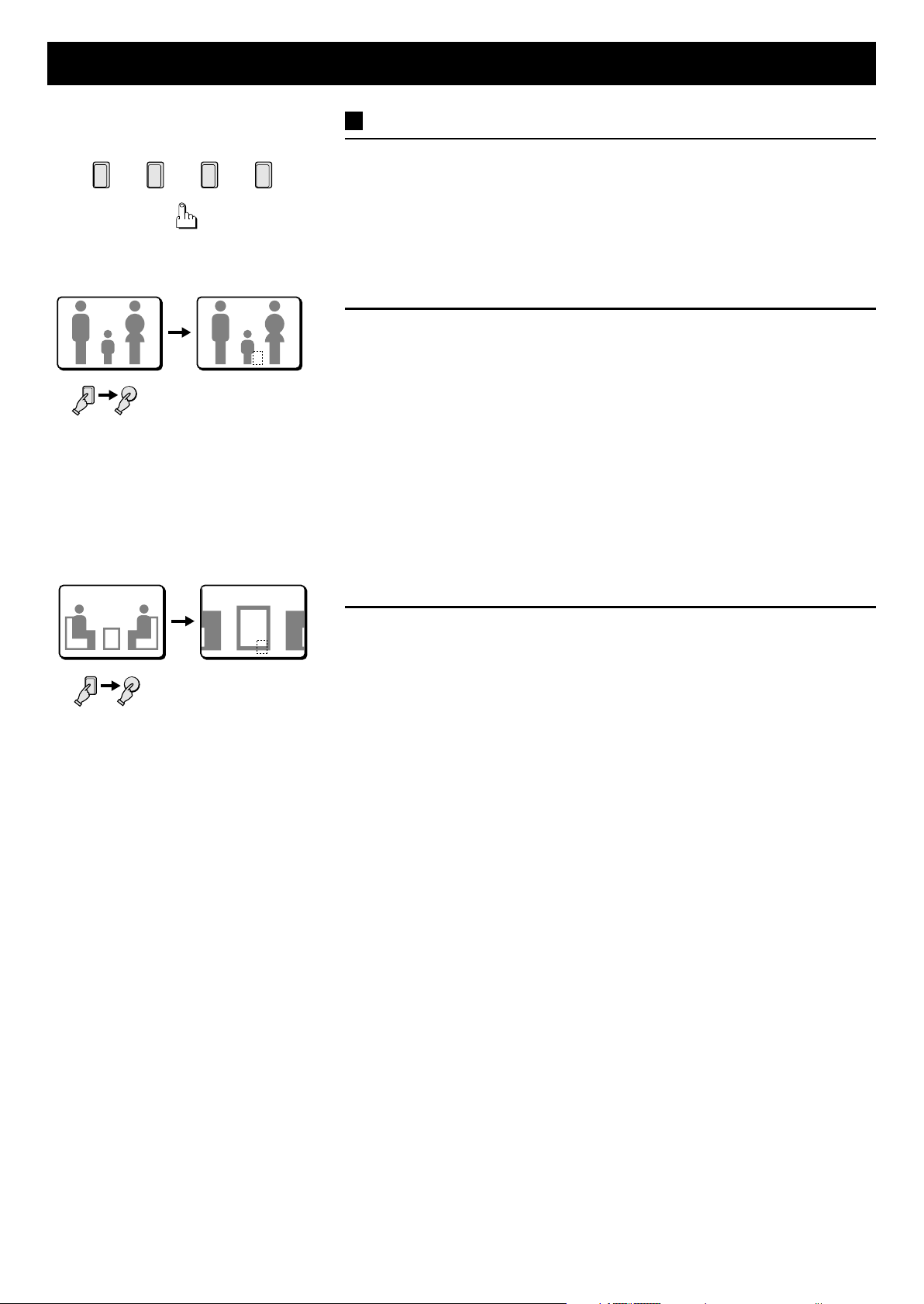
FULL SCREEN OPERATIONS
1
SEQUENCE
2
010101
...
8
9
010101
Press the LIVE button.
The camera SELECT indicator lights and the signal input at the CAMERA IN
terminals is displayed in full screen mode on the monitor screen.
If recording is started on the VCR, multiple live pictures feeds can be recorded
sequentially in full screen mode. For detailed information on the VCR MODE, REC
SPEED, etc. settings, please refer to (VCR SET) on page 26.
Press a SELECT (1 – 9) button.
The live pictures from the selected camera will be displayed full screen.
Automatic sequential full screen display
Press the SEQUENCE button.
The SEQUENCE indicator flashes. The pictures from each camera are displayed
sequentially full screen, on monitor, according to the monitor sequential mode and
speed set in the (MONITOR SET) menu (see page 32). The camera SELECT
indicators (1 – 9) light sequentially according to the displayed camera.
☞ To cancel the sequential display mode
Press the SEQUENCE button or the SELECT button.
ALARM OPERATION
01501
EA 05EA 05
When an alarm trigger, from a door bell, an interphone, etc., is input at the rear
panel ALARM IN terminals, the alarm channel pictures and the camera number
are displayed with “EA” (External Alarm) and the camera title shown
alternatively at the bottom of the screen. The corresponding camera SELECT
indicator will flash.
When the alarm operations are finished, the display mode will return to the previously
selected mode (full screen or sequential screen mode).
NOTE: If two or more alarms are received at the same time, the alarm channels are
displayed sequentially in order for about 1 second each. To display only one
of the alarm channels, press the corresponding SELECT button. The selected
alarm channel camera SELECT indicator will light. To return to sequential
display of all the alarm channels, press the same SELECT button one more
time.
English 11
Page 13
FIELD SWITCHER MODE VCR playback mode
To select the field switcher mode, in the (MONITOR SET) menu set MULTI MODE to OFF. (see page 32)
VCR PLAYBACK MODE
VCR
Press the VCR button.
The VCR playback display mode is selected. When a tape is played back, the
recording on the tape will be displayed on the monitor.
NOTE:
During VCR playback there is no output at the VCR OUT terminal and recording is
•
therefore not possible.
When playing back a tape recorded in multi-viewer mode (MULTI MODE set to
•
ON), the pictures will only be played back as recorded and it will therefore not be
possible to switch the display mode (full screen or split screen).
VCR PLAYBACK MODE OPERATIONS STEPS ON MONITOR
Full screen operations (see page 13)
•
(Full screen) (Still image) (Zoomed in still image)
4
STILL
0404 S 04S 04S 04 SZ 04SZ 04SZ 04
(Zoomed in image)
ZOOM
Press for 3 seconds
ZOOM
Press for 3 seconds
or more
or more
4
(Zoom range setting)
Multi-display screen operations
•
(see page 15)
9 divisions split screen
MULTI
4
0101 020202 030303
0404 050505 060606
0707 080808 090909
Z 04Z 04
(Automatic sequential
display)
SEQUENCE
0404
4 divisions split screen operations (see page 15)
•
(4 divisions split screen: 1 - 4) (4 divisions split screen: 5 - 8) (4 divisions split screen: 9)
QUAD QUAD
01 02
01 02
03 04
03 04
(Automatic sequential display)
SEQUENCE
01 02
01 02
03 04
03 04
0707
STILL
QUAD
05 0605 06
0707
0606
0808
(Zoomed in still image)
SZ 04SZ 04SZ 04
QUAD
0808
0909
12 English
Page 14
FIELD SWITCHER MODE VCR playback mode
FULL SCREEN OPERATIONS
1
2
...
0202 S 02S 02
STILL
2
8
9
Press a SELECT (1 – 9) button.
The recorded pictures are displayed full screen.
Example: To freeze the image from camera 2
1 Press the SELECT 2 button.
The camera 2 indicator lights, the image from camera 2 is displayed full screen.
2 Press the STILL button.
The STILL indicator flashes and “S” flashes on-screen.
NOTE: When a still image is displayed, press the ZOOM button for a zoomed in
still image. To return to normal still image display, press the ZOOM
button one more time.
☞ To cancel the still image display mode
Press the STILL button.
If another mode button is pressed, the still image display mode is cancelled and
the selected mode starts.
Example: To zoom in the image from camera 3
0303 Z 03Z 03
ZOOM
3
1 Press the SELECT 3 button.
The camera 3 indicator lights, the image from camera 3 is displayed full screen.
2 Press the ZOOM button.
The ZOOM indicator flashes and “Z” flashes on-screen.
NOTE: The zoomed in area will be as set by the zoom range frame.
☞ To cancel the zoomed in image display mode
Press the ZOOM button.
If another mode button is pressed, the selected mode starts.
English 13
Page 15
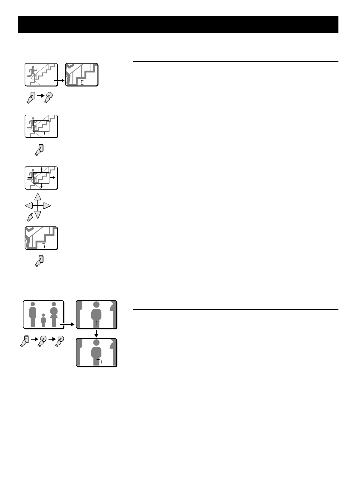
FIELD SWITCHER MODE VCR playback mode
Example: To zoom in the image from camera 4 and set the
zoom range
1
2
040404
ZOOM
4
Z 04Z 04Z 04
You can select the portion of the image to zoom in. The default zoomed in area is the
centre of the image, but if a different zoom range is selected it will be memorized until
changed or cancelled.
1 Press the SELECT 4 button.
The camera 4 indicator lights, the image from camera 4 is displayed full screen.
2 Press the ZOOM button.
3
The ZOOM indicator flashes and “Z” flashes on-screen.
3 Press the SELECT 4 button for about 2 seconds.
Z 04Z 04Z 04
4
4
The zoomed in image will switch to the normal display mode, and the zoom range
frame is displayed.
NOTE: If the zoom range frame is not moved for about 10 seconds, the display
will automatically return to zoomed in mode.
To display the zoom range frame again, press the SELECT 4 button for
about 2 seconds.
4 Press the j, l, d or c button repeatedly to move the zoom range frame to
Z 04Z 04Z 04
the desired area of the image.
5 Press the SELECT 4 button.
The area selected by the zoom range frame is now zoomed in. If necessary,
follow the same procedure to set the zoom range for the other cameras.
5
Z 04Z 04Z 04
4
☞ To cancel the zoomed in image display mode
Press the ZOOM button.
If another mode button is pressed, the selected mode starts.
Example: To freeze the zoomed in image from camera 2
1 Press the SELECT 2 button.
0202 Z 02Z 02
STILL
ZOOM
2
The camera 2 indicator lights, the image from camera 2 is displayed full screen.
2 Press the ZOOM button.
The image from camera 2 is zoomed in, and “Z” flashes on-screen.
3 Press the STILL button.
SZ 02SZ 02
The STILL indicator flashes and the ZOOM indicator lights. The camera 2
zoomed in image is frozen, and “SZ” flashes on-screen.
☞ To cancel the still and zoomed in image display modes
Press the STILL button, then press the ZOOM button.
If another mode button is pressed, the selected mode starts.
14 English
Page 16
FIELD SWITCHER MODE VCR playback mode
Automatic sequential full screen display
Press the SEQUENCE button.
The SEQUENCE indicator flashes. The pictures from each camera are displayed
sequentially full screen, on monitor, according to the monitor sequential mode and
speed set in the (MONITOR SET) menu (see page 32). The camera SELECT
indicators (1 – 9) light sequentially according to the displayed camera.
☞ To cancel the sequential display mode
Press the SEQUENCE button or the SELECT button.
SEQUENCE
010101
010101
01 02
01 02
03 04
03 04
QUAD
0101 0202
01 02
0303 0404
03 04
SEQUENCE
QUAD
0101 0202
01 02
0303 0404
03 04
05 0605 06
0707
0505 060605 06
070707
4 DIVISIONS SPLIT SCREEN OPERATIONS
Press the QUAD button.
The 4 divisions split screen display mode will be selected.
Switching the 4 divisions split screen
Press the QUAD button.
0808
Every time the QUAD button is pressed a 4 divisions split screen (1 - 4, 5 - 8, 9) is
selected. The camera SELECT indicators light according to the displayed cameras.
Automatic sequential 4 divisions split screen display
Press the SEQUENCE button.
080808
The SEQUENCE indicator flashes. The 4 divisions split screens are displayed
sequentially according to the 4 divisions split screen sequential mode and speed set
in the (MONITOR SET) menu (see page 32). The camera SELECT indicators (1 - 4, 5
- 8, 9) light sequentially according to the displayed 4 divisions split screen.
☞ To cancel the sequential display mode
Press the SEQUENCE button or the SELECT button.
MULTI-DISPLAY SCREEN OPERATIONS
MULTI
0101 020202 030303
Press the MULTI button.
0404 050505 060606
0707 080808 090909
The 9 divisions split screen display mode will be selected.
NOTE: The display position of each camera within the 9 divisions split screens can
be set as desired (see page 40).
ALARM OPERATION
0101
0202 030303
0404
0505 060606
0707 080808 090909
A
English 15
When a tape with alarm triggers is played back, “A” will be displayed flashing for the
cameras where the alarm triggers were received.
NOTE: In VCR playback mode, if there is an external alarm or a sensor alarm trigger,
the corresponding camera SELECT indicator will flash and the buzzer will be
heard (if BUZZER is set to ON, see page 28).
Page 17

MULTI-VIEWER MODE Live picture mode
To select the multi-viewer mode, in the (MONITOR SET) menu set MULTI MODE to ON. The display on the monitor will switch
to split screen mode (see page 32).
LIVE PICTURE MODE
LIVE
Press the LIVE button.
The camera SELECT indicator lights and the signal input at the CAMERA IN
terminals is displayed on the monitor screen.
If recording is started on the VCR, the live pictures will be recorded as displayed on
the monitor (full screen or split screen). For detailed information on the VCR MODE,
REC SPEED, etc. settings, please refer to (VCR SET) on page 26.
LIVE PICTURE MODE OPERATIONS STEPS ON MONITOR
Full screen operations (see page 17)
•
(Full screen) (Still image) (Zoomed in still image)
4
STILL
0404 S 04S 04S 04 SZ 04SZ 04SZ 04
(Zoomed in image)
ZOOM
Press for 3 seconds
Z 04Z 04
ZOOM
Press for 3 seconds
or more
or more
4
(Zoom range setting)
Multi-display screen operations
•
(see page 19)
9 divisions split screen
MULTI
4
0101 020202 030303
0404 050505 060606
0707 080808 090909
(Automatic sequential
display)
SEQUENCE
0404
4 divisions split screen operations (see page 19)
•
(4 divisions split screen: 1 - 4) (4 divisions split screen: 5 - 8) (4 divisions split screen: 9)
QUAD QUAD
01 02
01 02
03 04
03 04
(Automatic sequential display)
SEQUENCE
01 02
01 02
03 04
03 04
0707
STILL
QUAD
05 0605 06
0707
0606
0808
(Zoomed in still image)
SZ 04SZ 04SZ 04
QUAD
0808
0909
16 English
Page 18

MULTI-VIEWER MODE Live picture mode
1
2
...
0202 S 02S 02
STILL
2
8
9
FULL SCREEN OPERATIONS
Press a SELECT (1 – 9) button.
The live pictures from the selected camera will be displayed full screen.
Example: To freeze the image from camera 2
1 Press the SELECT 2 button.
The camera 2 indicator lights, the image from camera 2 is displayed full screen.
2 Press the STILL button.
The STILL indicator flashes and “S” flashes on-screen.
NOTE: When a still image is displayed, press the ZOOM button for a zoomed in
still image. To return to normal still image display, press the ZOOM
button one more time.
☞ To cancel the still image display mode
Press the STILL button.
If another mode button is pressed, the still image display mode is cancelled and
the selected mode starts.
Example: To zoom in the image from camera 3
0303 Z 03Z 03
ZOOM
3
1 Press the SELECT 3 button.
The camera 3 indicator lights, the image from camera 3 is displayed full screen.
2 Press the ZOOM button.
The ZOOM indicator flashes and “Z” flashes on-screen.
NOTE: The zoomed in area will be as set by the zoom range frame.
☞ To cancel the zoomed in image display mode
Press the ZOOM button.
If another mode button is pressed, the selected mode starts.
English 17
Page 19

MULTI-VIEWER MODE Live picture mode
Example: To zoom in the image from camera 4 and set the
zoom range
1
2
040404
ZOOM
4
Z 04Z 04Z 04
You can select the portion of the image to zoom in. The default zoomed in area is the
centre of the image, but if a different zoom range is selected it will be memorized until
changed or cancelled.
1 Press the SELECT 4 button.
The camera 4 indicator lights, the image from camera 4 is displayed full screen.
2 Press the ZOOM button.
3
The ZOOM indicator flashes and “Z” flashes on-screen.
3 Press the SELECT 4 button for about 2 seconds.
Z 04Z 04Z 04
4
4
The zoomed in image will switch to the normal display mode, and the zoom range
frame is displayed.
NOTE: If the zoom range frame is not moved for about 10 seconds, the display
will automatically return to zoomed in mode.
To display the zoom range frame again, press the SELECT 4 button for
about 2 seconds.
4 Press the j, l, d or c button repeatedly to move the zoom range frame to
Z 04Z 04Z 04
the desired area of the image.
5 Press the SELECT 4 button.
The area selected by the zoom range frame is now zoomed in. If necessary,
follow the same procedure to set the zoom range for the other cameras.
5
Z 04Z 04Z 04
4
☞ To cancel the zoomed in image display mode
Press the ZOOM button.
If another mode button is pressed, the selected mode starts.
While in zoomed mode, if the SELECT button is pressed one more time,
depending on the movement of the subject, the image may be more or less
clear. Pressing the SELECT button repeatedly will produce the following
according to the image conditions.
Image with little or no movement (close to a still image)
•
The image of still objects will be clear, the picture quality of moving areas of
the image will be coarse.
Image with normal movement (people or vehicles)
•
The moving objects in the image will be clear, the picture quality of areas of
the image with little movement will be coarse.
Example: To freeze the zoomed in image from camera 2
1 Press the SELECT 2 button.
0202 Z 02Z 02
STILL
ZOOM
2
The camera 2 indicator lights, the image from camera 2 is displayed full screen.
2 Press the ZOOM button.
The image from camera 2 is zoomed in, and “Z” flashes on-screen.
3 Press the STILL button.
SZ 02SZ 02
The STILL indicator flashes and the ZOOM indicator lights. The camera 2
zoomed in image is frozen, and “SZ” flashes on-screen.
☞ To cancel the still and zoomed in image display modes
Press the STILL button, then press the ZOOM button.
If another mode button is pressed, the selected mode starts.
18 English
Page 20

MULTI-VIEWER MODE Live picture mode
Automatic sequential full screen display
Press the SEQUENCE button.
The SEQUENCE indicator flashes. The pictures from each camera are displayed
sequentially full screen, on monitor, according to the monitor sequential mode and
speed set in the (MONITOR SET) menu (see page 32). The camera SELECT
indicators (1 – 9) light sequentially according to the displayed camera.
☞ To cancel the sequential display mode
Press the SEQUENCE button or the SELECT button.
SEQUENCE
010101
010101
01 02
01 02
03 04
03 04
QUAD
0101 0202
01 02
0303 0404
03 04
SEQUENCE
QUAD
0101 0202
01 02
0303 0404
03 04
05 0605 06
0707
0505 060605 06
070707
4 DIVISIONS SPLIT SCREEN OPERATIONS
Press the QUAD button.
The 4 divisions split screen display mode will be selected.
Switching the 4 divisions split screen
Press the QUAD button.
0808
Every time the QUAD button is pressed a 4 divisions split screen (1 - 4, 5 - 8, 9) is
selected. The camera SELECT indicators light according to the displayed cameras.
Automatic sequential 4 divisions split screen display
Press the SEQUENCE button.
080808
The SEQUENCE indicator flashes. The 4 divisions split screens are displayed
sequentially according to the 4 divisions split screen sequential mode and speed set
in the (MONITOR SET) menu (see page 32). The camera SELECT indicators (1 - 4, 5
- 8, 9) light sequentially according to the displayed 4 divisions split screen.
☞ To cancel the sequential display mode
Press the SEQUENCE button or the SELECT button.
MULTI
0101 020202 030303
0404 050505 060606
MULTI-DISPLAY SCREEN OPERATIONS
Press the MULTI button.
0707 080808 090909
English 19
The 9 divisions split screen display mode will be selected.
NOTE: The display position of each camera within the 9 divisions split screens can
be set as desired (see page 40).
Page 21

MULTI-VIEWER MODE Live picture mode
ALARM OPERATIONS
When an alarm trigger, from a door bell, an interphone, etc., is input at the rear panel
ALARM IN terminals, the corresponding camera SELECT indicator flashes and the
buzzer is heard. The alarm channel pictures are displayed according to the (ALARM
SET) menu settings (see page 28).
Example 1: The alarm channel pictures viewed in full
screen mode
(ALARM SET)
DURATION 10 S
RETRIGGER OFF
BUZZER ON
DATA ON
MON OUT FULL
DOUBLE ALARM LAST
(SENSOR SET)
SENSOR ALARM OFF
DURATION 10 S
0101
0202 030303
0404
0505 060606
0707 080808 090909
(ALARM SET)
DURATION 10 S
RETRIGGER OFF
BUZZER ON
DATA ON
MON OUT MULTI9
(SENSOR SET)
SENSOR ALARM OFF
DURATION 10 S
0101
0202 030303
0404
0505 060606
0707 080808 090909
0707 080808 090909
EA 06EA 06
EA 05EA 05
In the (ALARM SET) menu, set MON OUT to FULL.
When an alarm trigger is input, the alarm channel pictures and the camera number
are displayed with “EA” (External Alarm) and the camera title shown alternatively at
the bottom of the screen.
If two or more alarms are received at the same time, they are displayed according to
the DOUBLE ALARM setting.
Example 2: The alarm channel pictures viewed in
9 divisions screen mode
In the (ALARM SET) menu, set MON OUT to MULTI9.
When an alarm trigger is received, the display switches to a 9 divisions screen. The
alarm channel pictures are displayed with “EA” (External Alarm) and the camera title
shown alternatively.
To cancel an alarm channel pictures
To cancel an alarm pictures display, press the corresponding SELECT button.
The alarm pictures display will be cancelled, but not the alarm operations.
To cancel the alarm operations
If the alarm is viewed in full screen mode, press the corresponding SELECT button.
If the alarm is viewed in 9 divisions screen mode, press the corresponding SELECT
button twice.
20 English
Page 22

MULTI-VIEWER MODE VCR playback mode
To select the multi-viewer mode, in the (MONITOR SET) menu set MULTI MODE to ON. The display on the monitor will switch
to split screen mode (see page 32).
VCR PLAYBACK MODE
VCR
Press the VCR button.
The VCR playback display mode is selected. When a tape is played back, the
recording on the tape will be displayed on the monitor.
NOTE:
During VCR playback there is no output at the VCR OUT terminal and recording is
•
therefore not possible.
When playing back a tape recorded in multi-viewer mode (MULTI MODE set to
•
ON), the pictures will only be played back as recorded and it will therefore not be
possible to switch the display mode (full screen or split screen).
When playing back a tape recorded in field switcher mode, even if the viewing
•
mode is set to multi-viewer, the display of the playback picture will be the recorded
field switcher mode.
VCR PLAYBACK MODE OPERATIONS STEPS ON MONITOR
Full screen operations (see page 17)
•
4 divisions split screen operations (see page 19)
•
Multi-display screen operations (see page 19)
•
English 21
Page 23

MENU SETTING MODE
MENUS DISPLAYS
To display the menus, press the MENU button.
(Monitor)
0101
EXIT
MENU
Menu 1
(LANGUAGE/LANG./SPRACHE)
ENGLISH
FRANCAIS
DEUTSCH
MENU
Menu 2
(CLOCK SET)
01-01-2000 SAT 00:00:00
(TIMER SET)
DAYTIME 00:00-00:00
(SUMMER TIME SET)
MODE NO USE
WEEK MON TIME
ON LST-SUN 03 02:00
OFF LST-SUN 10 02:00
MENU
Menu 3
(VCR SET)
VCR MODE TLS
REC SPEED 3 H
ALARM REC SPEED 3 H
PROGRAM REC MODE OFF
(SERIAL SET)
DATA SPEED 19200
ALARM SEND OFF
ööADDRESS:000öö
MENU
Menu 4
(ALARM SET)
DURATION 10 S
RETRIGGER OFF
BUZZER ON
DATA ON
MON OUT FULL
DOUBLE ALARM LAST
(SENSOR SET)
SENSOR ALARM OFF
DURATION 10 S
MENU
Menu 5
(ACTIVE REC SET)
EXT ALARM REC OFF
SENSOR REC OFF
REC MODE MODE2
(VIDEO LOSS SET)
VIDEO LOSS OFF
DISPLAY FREEZE
DATA ON
MENU
Menu 6
(MONITOR SET)
MON. SEQ.TIMER 1 S
QUAD SEQ.TIMER 1 S
MON. SEQ.MODE MODE1
MON.MASK LIVE ON
MON.MASK VCR ON
MULTI MODE OFF
MENU
Menu 7
(CAMERA SET) NO.01
TITLE
DAY NIGHT
PROGRAM REC OFF OFF
MON.MASK OFF OFF
SEQUENCE 1 S 1 S
VIDEO LOSS ON
SENSOR SET : PRESS NEXT
--------
MENU
Menu 8
(POSITION SET)
MULTI 9
01 02 03
04 05 06
07 08 09
MENU
Menu 9
(DISPLAY SET)
LIVE CLOCK OFF
TITLE ON
VCR PB CLOCK OFF
TITLE ON
TITLE POSITION DOWN
CLOCK POSITION SET
† PRESS NEXT
MENU
Menu 10
(ALARM DATA) 1/ 1
CAM DATE TIME ITEM
Menu display
01
----------------
----------------
----------------
----------------
----------------
----------------
----------------
NEXT
----------------
----------------
----------------
LEVEL:DAY†OFF NIGHT†OFF MODE:A
NEXT
01-01-2000 00:00:00
ñ
MENU
0101
Live picture display
22 English
Page 24

LANGUAGE SETTING Menu 1
(LANGUAGE/LANG./SPRACHE)
The default menu language is English. The available language
settings are English, French and German.
Setting the language
1 Press the MENU button once to display the
(LANGUAGE/LANG./SPRACHE) menu.
2 Press the l button to highlight the desired language.
3
Press the MENU button to go to the next menu, or
☞
Press the EXIT button to exit the menu display and
☞
the selected language is set.
All the on-screen menus and settings will be displayed in
the selected language.
(HORLOGE)
(LANGUAGE/LANG./SPRACHE)
ENGLISH
FRANCAIS
DEUTSCH
01-01-2000 SAM 00:00:00
(PROGRAMMATEUR)
JOUR 00:00-00:00
(HEURE ETE)
MODE NON
SEM. MOIS HEURE
MAR DER-DIM 03 02:00
ARR DER-DIM 10 02:00
MENU
(UHRZEIT)
01-01-2000 SA 00:00:00
(TIMER EINST.)
TAGESZEIT 00:00-00:00
(SOMMERZEIT EINST.)
ART AUS
WOCHE MT ZEIT
EIN LZT-SO 03 02:00
AUS LZT-SO 10 02:00
English 23
Page 25

CLOCK AND SUMMER TIME SETTING
Menu 2
(CLOCK SET)
The default setting is as indicated below. The clock will start after
the actual time and date are set and the operations under
(TIMER SET) are completed.
Default clock settings: 01-01-2000 SAT 00:00:00
(January 1, 2000 at 00:00)
1 Press the MENU button twice to display the (CLOCK
SET) menu.
2 Example: Setting the clock to O ct ober 15, 1999 at 3:20 PM
1 Press the + (or –) button to set the day (15), then press
the c button.
2 Press the + (or –) button to set the month (10), then
press the c button.
3 Press the + (or –) button to set the year (1999), then
press the c button.
4 Press the + (or –) button to set the hours (15), then press
the c button.
5 Press the + (or –) button to set the minutes (20), then
press the c button.
NOTE: The day of the week (FRI) will be automatically set
according to the date entered.
3
Press the l button to go to (TIMER SET).
☞
Press the MENU button to go to the next menu
☞
screen, or
Press the EXIT button to exit the menu display.
☞
2-
1
(CLOCK SET)
15-01-2000 SAT 00:00:00
2-
2~5
(CLOCK SET)
15-10-1999 FRI 15:20:00
(TIMER SET)
You can set a DAY and a NIGHT range for the 24 hour day
period, in order to set each camera mode and programmed
recording accordingly.
1 Set the daytime period start and end time.
2 Example: Day period from 7:30 AM to 7:30 PM
Night period from 7:30 PM to 7:30 AM
1 Using the + (or –) button, select (7) for the starting hour
of the DAYTIME period, then press the c button.
2 Using the + (or –) button, select (30) for the starting
minutes of the DAYTIME period, then press the c button.
NOTE:
The times for the day period only need to be set. The
•
night period will be automatically set accordingly.
If the day start and end time are the same, the DAYTIME
•
settings will be active 24 hours a day.
3
Press the MENU button to go to the next menu
☞
screen, or
Press the EXIT button to exit the menu display.
☞
3
(CLOCK SET)
15-10-1999 FRI 15:20:00
(TIMER SET)
DAYTIME 07:30-19:30
(SUMMER TIME SET)
MODE NO USE
WEEK MON TIME
ON LST-SUN 03 02:00
OFF LST-SUN 10 02:00
End time
Start time
NOTE: To set the display mode for the clock, refer to
“DISPLAY SET (CLOCK, TITLE)” on page 41.
24 English
Page 26

CLOCK AND SUMMER TIME SETTING Menu 2
(SUMMER TIME SET)
The default summer time function setting is “NO USE”, so the
summer adjustment will not be made.
If the unit will be used in an area where there is a summer time
change, set it to “USE”, then if necessary, set when the summer
time is changed.
The default settings are:
Summer time from the last Sunday of March, at 2:00 AM
(LST-SUN 03 02:00) to last Sunday of October, at 2:00 AM
(LST-SUN 10 02:00).
TO MAKE CHANGES TO THE SETTINGS
1 Press the l button to highlight the “NO USE” setting,
then press the + (or –) button to select “USE”, and
press the l button one more time.
2 Example: Setting the summer time from the second
Tuesday of May at 3:00 AM, to the fourth
Tuesday of September at 3:00 AM.
1 Press the + (or –) button to set the WEEK (2ND), then
press the c button.
Menu: 1ST, 2ND, 3RD, 4TH or LST (first, second, third,
fourth or last)
2 Press the + (or –) button to set the WEEK (TUE), then
press the c button.
Menu: SUN, MON, TUE, WED, THU, FRI or SAT
3 Press the + (or –) button to set the MON (05), then press
the c button.
Menu: 1, 2, 3, 4 ..... 11, 12
(for January, February, March ..... December)
4 Press the + (or –) button to set the TIME (03), then press
the l button.
Following the same procedure as above, set when the
•
time is changed back from summer time to standard time
(the OFF settings).
3
Press the MENU button to go to the next menu
☞
screen, or
Press the EXIT button to exit the menu display.
☞
12-
(SUMMER TIME SET)
MODE USE
WEEK MON TIME
ON LST-SUN 03 02:00
OFF LST-SUN 10 02:00
2-
2
(SUMMER TIME SET)
MODE USE
WEEK MON TIME
ON 2ND-TUE 03 02:00
OFF LST-SUN 10 02:00
2-
4
(SUMMER TIME SET)
MODE USE
WEEK MON TIME
ON 2ND-TUE 05 03:00
OFF LST-SUN 10 02:00
1
(SUMMER TIME SET)
MODE USE
WEEK MON TIME
ON 2ND-SUN 03 02:00
OFF LST-SUN 10 02:00
2-
3
(SUMMER TIME SET)
MODE USE
WEEK MON TIME
ON 2ND-TUE 05 02:00
OFF LST-SUN 10 02:00
English 25
Page 27

VCR SETTING AND EXTERNAL CONTROL
COMMUNICATION SPEED SETTING Menu 3
(VCR SET)
You must set this unit output to match the type (Timelapse or
Real time VCR) and settings of the VCR used for recording.
Setting the VCR Output
1 Press the MENU button 3 times to display the (VCR
SET) menu.
2 Using the + (or –) button, select the desired “VCR
MODE” setting, then press the l button.
Following this procedure, select the settings for REC
SPEED, ALARM REC SPEED and PROGRAM REC
MODE.
3
Press the l button to go to the (SERIAL SET) menu,
☞
or
Press the MENU button to go to the next menu
☞
screen, or
Press the EXIT button to exit the menu display.
☞
(Timelapse VCR) (Real time VCR)
2
(VCR SET)
VCR MODE TLS
REC SPEED 3 H
ALARM REC SPEED 3 H
PROGRAM REC MODE OFF
VIDEO LOSS ON
DATA ON
DISPLAY FREEZE
<RS232C SET>
VCR SET menu
If the VCR is not Equipped with a SW (switching) Output
Connector
VCR MODE
TLS: If using a timelapse VCR. (Default setting)
REAL: If using a real time VCR.
REC SPEED
The recording speed settings on this unit correspond to
recording durations on a E-180 tape.
With a timelapse VCR
Set the recording speed to match the recording speed of the
timelapse VCR.
The available speeds are: 3H (Default setting), 12H, 24H, 48H,
72H, 96H, 120H, 168H, 240H, 360H, 480H, 720H, 960H
With a real time VCR
Set the recording speed to match the recording speed of the real
time VCR.
The available speeds are: 6H (Default setting), 18H, 30H, 48H,
72H, 96H, 120H, 168H, 240H, 360H, 480H, 720H, 960H
NOTE: Real time VCRs speed is based on a E-240 cassette
tape. When setting this unit to 6H, 18H or 30H, refer to
the table 1 for the speed correspondence, and select
the speed on the VCR accordingly.
(VCR SET)
VCR MODE REAL
REC SPEED 6 H
ALARM REC SPEED 6 H
PROGRAM REC MODE OFF
VIDEO LOSS ON
DATA ON
DISPLAY FREEZE
<RS232C SET>
Table 1
REC SPEED setting
6H 8H (8-hour mode)
18H 24H (24-hour mode)
30H 40H (40-hour mode)
Recording speed setting on the
real time VCR
ALARM REC SPEED
With a timelapse VCR
Set the recordi ng speed to use when an alarm t rig ger is rec eived to
match the ala rm reco rdin g speed of the timel apse VC R.
The available speeds are:
3H (Default setting), 12H, 24H, NC, F3
When an alarm trigger is received, the recording speed is not
NC:
changed and stays as set under “REC SPEED”.
F3: Use this setting when using the SW output terminal on a timelapse
VCR that does not output a switching signal in 3H mode.
With a real time VCR
Set the recordi ng speed to use when an alarm t rig ger is rec eived to
match the alarm recording speed of the real time VCR.
The available speeds are:
6H (Default setting), 18H, NC, F6
NC: When an alarm trigger is received, the recording speed is
not changed and stays as set under “REC SPEED”.
F6: Use this setting w hen usi ng t he SW output terminal on a real
time VCR that does not output a switching signal in 6H mode.
PROGRAM REC MODE (Default setting: OFF)
Using the programmed recording mode you can decided to only
output the recorded live pictures from a certain camera or to give
priority to the pictures from a certain camera.
This will set the programmed recording mode.
MODE1:
MODE2: The live pictures from the camera for which programmed
OFF: Programmed recording will not be done.
NOTE:
•
•
•
•
Only the live pictures from the camera for which programmed
recording is set are recorded.
recording is set are recorded together with the live pictures
from the other cameras.
Programmed recording of multiple cameras is done by switching to
each camera in order.
In the (CAMERA SET) menu, set for each camera if programmed
recording is to be conducted or not (see page 33).
The recording mode set here is the same as the ACTIVE REC
recording mode (see page 30). The programmed recording mode is
the normal recording mode applied to the camera, while the active
recording mode will modify the recording mode for the camera when
an external alarm or a video sensor trigger is received.
Any camera for which programmed recording is turned off, will not be
recorded when an external alarm or a video sensor trigger is
received. To record from a camera for which programmed recording
is turned off, when an external alarm or a video sensor trigger is
received, set the active recording mode to on.
26 English
Page 28

VCR SETTING AND EXTERNAL CONTROL COMMUNICATION
(SERIAL SET)
DATA SPEED 19200
ALARM SEND OFF
ööADDRESS:000öö
(SERIAL SET)
DATA SPEED 19200
ALARM SEND OFF
ööADDRESS:000öö
)
SPEED SETTING Menu 3
If the VCR is Equipped with a SW (switching) Output
Connector (using the VCR switching signal)
Make the connection from this unit to the VCR SW output
connector. The video signal output by this unit will be
automatically switched to the recording speed according to the
switching signal output by the VCR (switching pulse setting on
the VCR).
The (VCR SET) menu “REC SPEED” and “ALARM REC
SPEED” items do not need to be set.
If a switching signal is not output at the switching terminal
Some VCR models may not output a switching signal in 3H or
6H mode. In such a case, make the settings as indicated in the
table below.
VCR SET menu settings Timelapse VCR Real time VCR
REC SPEED
ALARM REC SPEED
3H 6H
F3 F6
NOTE: When the recording speed is set to F3 or F6, the alarm
recording speed is fixed to 3H or 6H. Therefore, when
using a recording speed other than 3H or 6H, do not use
the F3 or F6 setting.
(SERIAL SET)
Connect the multiplexer to a computer, using a 9-pin D-SUB
cable (sold separately), then set the maximum communication
speed between the unit and the computer.
For detailed information, please refer to “INTERFACE
SPECIFICATIONS” on page 45.
Setting the RS232C/RS485 communication
1 Press the l button to highlight the setting to modify.
2 Using the + (or –) button, select the desired “DATA
SPEED” setting, then press the l button.
3 Using the + (or –) button, select the desired “ALARM
SEND” setting.
SERIAL SET menu
DATA SPEED (Default setting: 19200 bps)
The available settings are: 2400, 4800, 9600, 19200 bps
ALARM SEND (Default setting: OFF)
ON: The alarm information is output at the RS232C/RS485
terminals.
OFF: The alarm information is not output at the RS232C/RS485
terminals.
Unit address confirmation
If multiple units are going to be controlled through a system
controller (sold separately) via the RS485 connection, each unit
must have a address for remote control purposes. The address
set for the unit can be checked by accessing the (VCR SET)
menu.
1 Press the MENU button three times to display the (VCR
SET) menu.
The unit address is displayed on the last line of the menu.
The unit address can be set using the Interface setting DIP
switches on the back panel of the unit. (see page 46)
2
Press the MENU button to go to the next menu
☞
screen, or
Press the EXIT button to exit the menu display.
☞
1
(VCR SET)
VCR MODE TLS
REC SPEED 3 H
ALARM REC SPEED 3 H
PROGRAM REC MODE OFF
(SERIAL SET)
DATA SPEED 19200
ALARM SEND OFF
ööADDRESS:000öö
Address (000 – 127
(Interface setting DIP switches)
ON
12345678910
ON
OFF
4
Press the MENU button to go to the next menu
☞
screen, or
Press the EXIT button to exit the menu display.
☞
2
3
English 27
Page 29

ALARM AND SENSOR SETTING Menu 4
(ALARM SET)
When an alarm trigger is received from sensors such as a door
bell, movement sensor, etc. you can set the display mode and
the recording mode for the pictures from the concerned camera.
Using the (SENSOR SET) settings (see page 29), the triggers
received from the video sensors can be set to operate as alarm
triggers.
Changing the Settings
1 Press the MENU button 4 times to display the (ALARM
SET) menu.
2 Using the + (or –) button, select the desired setting,
then press the l button.
Repeat step 2, until all the settings are as desired.
•
3
Press the l button to go to the (SENSOR SET)
☞
menu, or
Press the MENU button to go to the next menu
☞
screen, or
Press the EXIT button to exit the menu display.
☞
2
(ALARM SET)
DURATION 10 S
RETRIGGER OFF
BUZZER ON
DATA ON
MON OUT FULL
DOUBLE ALARM LAST
ALARM SET menu
DURATION (Default setting: 10 S)
The available durations are (seconds):
1, 2, 3, 4, 5, 10, 20 (in 10 seconds increments)... 180,
CC, NC, INDIV., OFF
CC: The alarm will go on as long as the alarm signal is
received (minimum 1 second).
NC: The alarm will continue until reset.
INDIV.:The alarm duration will be as set for each of the cameras.
OFF: No alarm duration setting.
NOTE: If the “INDIV.” setting is used, in the (CAMERA SET)
menu, enter the desired alarm duration for each
camera (see page 33).
DATA (Default setting: ON)
ON: The alarm data is recorded.
OFF: The alarm data is not recorded.
MON OUT
In the MONITOR SET menu, when MULTI MODE is set to ON,
set MONITOR OUT to FULL, MULTI 9 or NC.
(A)
(ALARM SET)
DURATION 10 S
RETRIGGER OFF
BUZZER ON
DATA ON
MON OUT FULL
DOUBLE ALARM LAST
(SENSOR SET)
SENSOR ALARM OFF
SENSOR DURATION 10 S
(B)
(ALARM SET)
DURATION 10 S
RETRIGGER OFF
BUZZER ON
DATA ON
MON OUT MULTI9
(A) FULL (Default setting):
If an alarm trigger is received, the picture from the camera
corresponding to the alarm input will be displayed full
screen.
DOUBLE ALARM (Default setting: LAST)
•
When using the “FULL” setting at the “MON OUT” line,
the following settings are possible.
LAST: When triggers from multiple cameras are
received in full screen mode, the picture from the
camera of the last alarm received is displayed.
FIRST: When triggers from multiple cameras are
received in full screen mode, the picture from the
camera of the first alarm received only is displayed.
Camera pictures from subsequent alarm triggers will
not be displayed.
SWITCH: When triggers from multiple cameras are
received in full screen mode, the picture from each
concerned camera will be displayed sequentially at 1
second interval.
(B) MULTI9: When an alarm trigger is received, the display
will switch to a 9 divisions screen.
(C) NC: The display mode will remain unchanged when an
alarm trigger is received.
(C)
(ALARM SET)
DURATION 10 S
RETRIGGER OFF
BUZZER ON
DATA ON
MON OUT NC
(CAMERA SET) NO.01
TITLE
DAY NIGHT
PROGRAM REC OFF OFF
AL.DURATION 10 S 10 S
MON.MASK OFF OFF
--------
01
RETRIGGER (Default setting: OFF)
To set if an alarm is received while the unit is already in alarm
mode.
ON: During alarm mode, other alarm triggers will be received
and the alarm duration will be extended.
OFF: The unit will not receive another alarm, while one is
already being received.
BUZZER (Default setting: ON)
ON: A buzzer will be heard when an alarm trigger is received.
OFF: The buzzer will not be heard.
28 English
Page 30

ALARM AND SENSOR SETTING Menu 4
(SENSOR SET)
When the internal video sensor detects a movement in the live
video signal, it can be set to trigger an alarm. Priority recording
of the concerned pictures can also be set (ACTIVE REC).
Setting the SENSOR SET Mode
1 Press the l button to highlight the setting to modify.
2 Using the + (or –) button, select the desired “SENSOR
ALARM” setting, then press the l button.
Following this procedure, select the settings for “DURATION”.
3
Press the MENU button to go to the next menu
☞
screen, or
Press the EXIT button to exit the menu display.
☞
2
(SENSOR SET)
SENSOR ALARM OFF
DURATION 10 S
SENSOR SET menu
SENSOR ALARM (Default setting: OFF)
This will set if the internal video sensor triggers are considered
as alarm triggers.
ON: The sensor triggers will be considered as alarms, and
when received the display will switch to the selected alarm
display mode and the buzzer will be heard.
OFF: The sensor triggers are not considered as alarms.
AND:Only when a sensor trigger and an alarm trigger are
received simultaneously, it will be considered as an alarm.
NOTE: If SENSOR ALARM is set to AND, a trigger to an
ALARM IN terminal alone will not be considered as an
alarm.
DURATION (Default setting: 10 S)
When a video sensor detects a movement, this will set the active
recording mode duration (see page 30).
The available durations are:
1, 2, 3, 4, 5, 10, 20 (in 10 seconds increments)... 180
NOTE: When the SENSOR ALARM settings “ON” and “AND”
are used, the internal video sensor can trigger an alarm
operation. The alarm duration is set by the “DURATION”
setting in (ALARM SET) (see page 28).
English 29
Page 31

ACTIVE RECORDING AND VIDEO LOSS
SETTING Menu 5
(ACTIVE REC SET)
To set the priority recording mode when an external alarm or
video sensor trigger is received.
NOTE: If in the MONITOR SET menu, MULTI MODE is set to
ON, active recording will not be possible.
Setting the ACTIVE REC Recording Mode
1 Press the MENU button 5 times to display the (ACTIVE
REC SET) menu.
2 Using the + (or –) button select the desired “EXT
ALARM REC” setting, then press the l button.
All the other settings are selected using the same procedure.
3
Press the l button to go to the (VIDEO LOSS SET)
☞
menu, or
Press the MENU button to go to the next menu
☞
screen, or
Press the EXIT button to exit the menu display.
☞
2
(ACTIVE REC SET)
EXT ALARM REC OFF
SENSOR REC OFF
REC MODE MODE2
(VIDEO LOSS SET)
When the live picture signal feed is interrupted, you can set the
action taken (frozen picture or test chart), and if the video loss is
recorded as alarm data.
Setting the Video Loss Mode
1 Press the l button to highlight the “VIDEO LOSS”
setting.
2 Using the + (or –) button select the desired “VIDEO
LOSS” setting, then press the l button.
All the other settings are selected using the same procedure.
3
Press the MENU button to go to the next menu
☞
screen, or
Press the EXIT button to exit the menu display.
☞
3
(VIDEO LOSS SET)
VIDEO LOSS OFF
DISPLAY FREEZE
DATA ON
ACTIVE REC SET menu
EXT ALARM REC (Default setting: OFF)
ON: When an external alarm trigger is received, active recording is
initiated, the concerned camera pictures being recorded in priority.
OFF: When an external alarm trigger is received, active recording will
not be initiated.
SENSOR REC (Default setting: OFF)
ON:
When a video sensor trigger is received, active recording is
initiated, the concerned camera pictures being recorded in priority.
OFF: When a video sensor trigger is received, active recording will not
be initiated.
REC MODE (Default setting: MODE2)
This setting selects the active recording operations.
MODE1:
MODE2: The live pictures from the camera corresponding to the alarm
NOTE:
The live pictures from the camera corresponding to the alarm
trigger only are recorded.
trigger is recorded together with the signal from the other
cameras.
Please refer to “ACTIVE REC Settings Examples” on
page 31.
Programmed recording function will select the camera to record
or the camera priority recording normal mode, but the active
recording mode will modify the recording mode for that camera
when an external alarm or a video sensor trigger is received.
VIDEO LOSS SET menu
VIDEO LOSS (Default setting: OFF)
You can set the action to take when there is an interruption in
the video signal feed.
The video loss will not be active independently of the setting
OFF:
entered for each camera.
INDIV.: The ON/OFF setting will be as set for each of the cameras.
NOTE:
If the “INDIV.” setting is used, in the (CAMERA SET) menu,
enter the desired setting for each camera (see page 33).
DISPLAY (Default setting: FREEZE)
FREEZE: When there is a video loss, the image just previous to the
TEST: When there is a video loss, test chart are displayed on-screen.
NOTE: •
interruption is frozen on-screen.
Depending on the timing of the video loss, a complete
picture may not be displayed.
Even if a frozen image is selected for the monitor display,
•
test chart only can be recorded.
DATA (Default setting: ON)
ON:
The video losses data is recorded as alarm data.
OFF: The video losses data is not recorded.
NOTE: •
If the “ON” setting is used, you can review the video
losses data (camera number, date, time) in the (ALARM
DATA) menu (see page 42).
In field switcher mode, if there is a video loss, VIDEO
•
LOSS will be displayed on a grey screen. (A frozen
image or the test chart cannot be displayed.)
30 English
Page 32

ACTIVE RECORDING AND VIDEO LOSS SETTING Menu 5
gg
ACTIVE REC Settings Examples
Example 1: Recording on the tape when an alarm trigger is received from camera 2
Camera 2 picture
0202
(Normal)
01 02 04 05 06 07 08 09
01 02 03 04 05 06 07 08 09 0101 02 04 05 06 07 0801 02 03 04 05 06 07 08
(REC MODE: MODE1)
01 02 0201 02 03 04 02 020202 020202 020202 020202 020202 020202 020202 05 06 07 08
(REC MODE: MODE2)
01 02 03 01 02 0304 05 06 07 08 09
Normal recording
(no alarm trigger)
Alarm trigger in Alarm trigger out
Alarm duration for camera 2
Alarm trigger in Alarm trigger out
0202 020202 020202 020202
Alarm duration for camera 2
Example 2: Recording on the tape when an alarm trigger is received from camera 4 when an
alarm trigger has already been received from camera 2
Camera 2 picture Camera 4 picture
020202
040404
(Normal)
02
01 02 04 05 06 07 08 0901 03 04
(REC MODE: MODE1)
01 02 03 04
(REC MODE: MODE2)
01 02 03 04
05 06 07 08 09
Alarm trigger in Alarm trigger in
02 02 02 04 02 04 02 04 04 04 04 04 05 0602 02 02 04 02 04 02 04 04 04 04 04 05 06
Alarm duration for
camera 2
Alarm trigger in Alarm trigger in
02 05 02 04 06 02 07 04 08 04 09 0402 05 02 04 06 02 07 04 08 04 09 04
Alarm duration for
camera 2
Alarm trigger received from camera
4 during the alarm duration for
trigger from camera 2
Alarm trigger received from camera
4 during the alarm duration for
tri
01 02 04 05 06 07 0801 02 03 04 05 06 07 08
Alarm trigger out Alarm trigger out
Alarm duration for camera 2 is over,
remaining alarm duration for trigger
from camera 4
Alarm trigger out Alarm trigger out
Alarm duration for camera 2 is over,
er from camera 2
remaining alarm duration for trigger
from camera 4
01 02
NOTE: The ACTIVE REC examples are given for function illustration purposes only. The actual recordings will vary according to the
various settings.
English 31
Page 33

MONITOR SETTINGS Menu 6
You can set the automatic sequential display speed on each monitor and the display sequence order. You can also set the viewing
mode for live pictures to multi-viewer (4 or 9 divisions).
(MONITOR SET)
Setting the Monitor Display
1 Press the MENU button 6 times to display the
(MONITOR SET) menu.
2 Press the l button to highlight the setting to modify.
Using the + (or –) button, select the desired setting,
then press the l button.
Following this procedure, select the settings or MON SEQ.
TIMER ... MULTI MODE.
3
Press the MENU button to go to the next menu
☞
screen, or
Press the EXIT button to exit the menu display.
☞
2
(MONITOR SET)
MON. SEQ.TIMER 1 S
QUAD SEQ.TIMER 1 S
MON. SEQ.MODE MODE1
MON.MASK LIVE ON
MON.MASK VCR ON
MULTI MODE OFF
MONITOR SET menu
MON.MASK LIVE (Default setting: ON)
ON: If, for certain cameras, in the (CAMERA SET) menu, the
“MON.MASK” item is set to “ON”, the live picture from
those cameras will not be visible on-screen.
OFF: The live picture from all cameras will be visible on-screen
regardless of the “MON.MASK” item setting of each
camera, in the (CAMERA SET) menu.
MON.MASK VCR (Default setting: ON)
ON: If, for certain cameras, in the (CAMERA SET) menu, the
“MON.MASK” item is set to “ON”, the recorded picture
from those cameras will not be visible on-screen.
OFF: The recorded picture from all cameras will be visible
on-screen regardless of the “MON.MASK” item setting of
each camera, in the (CAMERA SET) menu.
NOTE:
The individual monitor masking setting is entered for each
camera in the (CAMERA SET) menu (see page 33).
MULTI MODE (Default setting: OFF)
OFF: The live pictures are only displayed in full screen mode.
ON: The live pictures are displayed in full screen or split screen
(4 or 9 divisions) mode.
NOTE:
If recording multiple live images feeds, set MULTI MODE to
OFF to record the pictures sequentially. If set to ON, the
pictures will be recorded as displayed (if displayed in a split
screen, they will be recorded as such).
MON. SEQ.TIMER (Default setting: 1 S)
To set the full screen automatic sequential display speed
(interval) on monitor.
The available intervals are: 1 – 30 seconds, INDIV.
QUAD SEQ.TIMER (Default setting: 1 S)
To set the 4 divisions screen automatic sequential display speed
(interval).
The available intervals are: 1 – 30 seconds
MON. SEQ.MODE (Default setting: MODE1)
MODE1: The cameras are displayed sequentially in order (1 to
9).
MODE2: The cameras are displayed sequentially in the order
set in the (POSITION SET) menu, when the 9 cameras
are displayed in a 9 divisions screen (see page 40).
32 English
Page 34

CAMERA SETTING Menu 7
(CAMERA SET) NO.01
TITLE
--------
01
DAY NIGHT
(CAMERA SET) NO.02
TITLE
--------
01
DAY NIGHT
(CAMERA SET) NO.03
TITLE
--------
01
DAY NIGHT
(CAMERA SET) NO.04
TITLE
--------
04
For each camera connected to the unit, you can enter a camera title, such as the camera location, etc., that will be displayed together
with the picture from that camera. Also, each camera operating mode and timer recording mode can be set.
(CAMERA SET)
1 Press the MENU button 7 times to display the (CAMERA
SET) menu.
2 The following settings are available.
When finished, press the EXIT button to exit the
☞
menu display.
Camera number
(CAMERA SET) NO.01
TITLE
A
DAY NIGHT
PROGRAM REC OFF OFF
B
MON.MASK OFF OFF
SEQUENCE 1 S 1 S
VIDEO LOSS ON
C
SENSOR SET : PRESS NEXT
D
A A camera title (up to 10 characters) to be displayed with
the live picture of the camera can be entered.
The camera title displayed location can be set in the
(DISPLAY SET) menu.
B A day period and a night period can be set and the
following actions can be set accordingly.
B1: PROGRAM REC
Set to ON (or OFF) for programmed recording (or no
programmed recording) for each camera.
B2: AL. DURATION
Set the alarm duration for each camera.
B3: MON. MASK
Set to ON (or OFF) for each camera, so that the image
from that camera is greyed out (or is not greyed out)
and is not visible on the monitor.
Also, in the (MONITOR SET) menu, you must set the
monitor masking to be applied to live and/or recorded
monitoring.
B4: SEQUENCE
Set the sequential display interval for each camera.
C VIDEO LOSS
Set to ON (or OFF), then in the (VIDEO LOSS SET)
menu set the “VIDEO LOSS” item to “INDIV.” and enter
each setting. If the video signal is interrupted during live
picture mode, the image just previous to the interruption
is frozen on-screen or test chart can be displayed.
However, the frozen image and test chart settings cannot
be used together.
D SENSOR SET
Sensor areas can be set for every camera screen in live
picture mode. By setting certain areas that operate as
video sensors, priority recording of the concerned
camera pictures can be done when a movement is
detected within the set sensor area.
--------
01
----------------
----------------
----------------
----------------
----------------
----------------
----------------
----------------
----------------
----------------
LEVEL:DAY†OFF NIGHT†OFF MODE:A
ñ
A Setting the camera title
Each camera is selected by pressing the appropriate SELECT (1
– 9) button.
Example: To set the title “HALL-1F” for camera 3
1 Press the SELECT (3) button.
2 Using the + (or –) button set the first character “H”, then
press the c button.
By pressing the + (or –) button repeatedly, the characters
are selected as follows:
Letters: A, B, C,....X, Y, Z
•
Numbers: 0, 1,....8, 9
•
Symbols: –, :, ., /, *, _ (blank space)
•
3 Following the same procedure, enter the rest of the title
“ALL-1F”.
☞ Press the MENU button to go to the next menu screen,
or
☞ Press the EXIT button to exit the menu display.
(CAMERA SET) NO.09
12
(CAMERA SET) NO.03
TITLE H
DAY NIGHT
PROGRAM REC OFF OFF
MON.MASK OFF OFF
SEQUENCE 1 S 1 S
VIDEO LOSS OFF
SENSOR SET : PRESS NEXT
-------
TITLE
03
3
(CAMERA SET) NO.03
TITLE HALL-1F-03
DAY NIGHT
PROGRAM REC OFF OFF
MON.MASK OFF OFF
SEQUENCE 1 S 1 S
VIDEO LOSS OFF
SENSOR SET : PRESS NEXT
--------
09
English 33
Page 35

CAMERA SETTING Menu 7
B1 Setting up programmed recording for each
camera
1 Press the MENU button twice to display the (TIMER
SET) menu, then check that the day and night periods
are set as desired. (For more information on the day
and night periods settings, see “TIMER SET” on page
24.)
2 Press the MENU button once to display the (VCR SET)
menu.
Press the l button to highlight the “PROGRAM REC
MODE” setting.
3 Using the + (or –) button, set “MODE1” or “MODE2”.
(For more information on each mode operation, see
“PROGRAM REC MODE” on page 26.)
4 Press the MENU button four times to display the
(CAMERA SET) menu.
5 Press the SELECT (1 – 9) button to select the desired
camera (ex: camera 5).
6 Press the l button to highlight the “PROGRAM REC”
setting.
1 Press the + (or –) button to set “ON” in the DAY column,
then press the c button.
2 Press the + (or –) button to set “ON” in the NIGHT
column.
Programmed recording will be conducted according to the
“MODE1” or “MODE2” setting entered in the (VCR SET)
menu.
7
Press the MENU button to go to the next menu
☞
screen, or
Press the EXIT button to exit the menu display.
☞
1
(CLOCK SET)
15-10-1999 FRI 15:20:00
(TIMER SET)
DAYTIME
(SUMMER TIME SET)
MODE NO USE
WEEK MON TIME
ON LST-SUN 03 02:00
OFF LST-SUN 10 02:00
07:30-19:30
MENU
2, 3
(VCR SET)
VCR MODE TLS
REC SPEED 3 H
ALARM REC SPEED 3 H
PROGRAM REC MODE OFF
(SERIAL SET)
DATA SPEED 19200
ALARM SEND OFF
ööADDRESS:000öö
MENU
4
(CAMERA SET) NO.01
TITLE
DAY NIGHT
PROGRAM REC OFF OFF
MON.MASK OFF OFF
SEQUENCE 1 S 1 S
VIDEO LOSS ON
SENSOR SET : PRESS NEXT
--------
MENU
OFF
MODE1
MODE2
5, 6
(CAMERA SET) NO.05
01
TITLE
DAY NIGHT
PROGRAM REC ON ON
MON.MASK OFF OFF
SEQUENCE 1 S 1 S
VIDEO LOSS ON
SENSOR SET : PRESS NEXT
5
--------
05
CAMERA SET menu
PROGRAM REC (Default setting: DAY and NIGHT to OFF)
ON: When the time set in the (TIMER SET) menu is reached,
the pictures from this camera will be recorded in priority.
OFF: Programmed recording will not be done.
34 English
Page 36

CAMERA SETTING Menu 7
B2 Setting the alarm duration for each camera
1 Press the MENU button twice to display the (TIMER
SET) menu, then check that the day and night periods
are set as desired. (For more information on the day
and night periods settings, see “TIMER SET” on page
24.)
2 Press the MENU button twice to display the (ALARM
SET) menu.
3 Using the + (or –) button, set “INDIV.” for the
“DURATION” item.
NOTE: In the (CAMERA SET) menu, the item
“AL.DURATION” will only be displayed if the
“DURATION” item is set to “INDIV. ”.
4 Press the MENU button three times to display the
(CAMERA SET) menu.
5 Press the SELECT (1 – 9) button to select the desired
camera (ex: camera 5).
6 Press the l button to highlight the “AL.DURATION”
setting.
1 Press the + (or –) button to set the desired duration
(ex: 20 sec.) in the DAY column, then press the c button.
2 Press the + (or –) button to set the desired duration
(ex: 30 sec.) in the NIGHT column.
If there is an alarm triggered, the alarm duration will be as
set for each camera.
7
Press the MENU button to go to the next menu
☞
screen, or
Press the EXIT button to exit the menu display.
☞
1
(CLOCK SET)
15-10-1999 FRI 15:20:00
(TIMER SET)
DAYTIME
(SUMMER TIME SET)
MODE NO USE
WEEK MON TIME
ON LST-SUN 03 02:00
OFF LST-SUN 10 02:00
07:30-19:30
MENU
2, 3
(ALARM SET)
DURATION INDIV.
RETRIGGER OFF
BUZZER ON
DATA ON
MON OUT FULL
DOUBLE ALARM LAST
(SENSOR SET)
SENSOR ALARM OFF
DURATION 10 S
MENU
4
(CAMERA SET) NO.01
TITLE
DAY NIGHT
PROGRAM REC OFF OFF
AL.DURATION 10 S 10 S
MON.MASK OFF OFF
SEQUENCE 1 S 1 S
VIDEO LOSS ON
SENSOR SET : PRESS NEXT
--------
MENU
5, 6
(CAMERA SET) NO.05
01
TITLE
DAY NIGHT
PROGRAM REC ON ON
AL.DURATION 20 S 30 S
MON.MASK OFF OFF
SEQUENCE 1 S 1 S
VIDEO LOSS ON
SENSOR SET : PRESS NEXT
5
--------
05
CAMERA SET menu
AL. DURATION (Default setting: DAY and NIGHT to 10 S)
If in the (ALARM SET) menu, the item “DURATION” is set to
“INDIV.”, enter the desired alarm duration for each camera.
The available durations are:
1, 2, 3, 4, 5, 10, 20 (in 10 seconds increments)... 180, CC,
NC, OFF
CC: The alarm will go on as long as the alarm signal is
received (minimum 1 second).
NC: The alarm will continue until reset.
OFF: No alarm duration setting.
English 35
Page 37

CAMERA SETTING Menu 7
B3 Setting the mo nitor ma sk i n g fo r e a c h camera
1 Press the MENU button twice to display the (TIMER
SET) menu, then check that the day and night periods
are set as desired. (For more information on the day
and night periods settings, see “TIMER SET” on page
24.)
2 Press the MENU button five times to display the
(CAMERA SET) menu.
3 Press the SELECT (1 – 9) button to select the desired
camera (ex: camera 5).
4 Press the l button to highlight the “MON.MASK”
setting.
1 Press the + (or –) button to set “ON” in the DAY column,
then press the c button.
2 Press the + (or –) button to set “ON” in the NIGHT
column.
5 Press the EXIT button to exit the menu mode and return
to live picture mode, then press the MENU button six
times to display the (MONITOR SET) menu.
6 Press the l button to highlight the “MON.MASK LIVE”
setting.
1 Press the + (or –) button to set “ON” for the “MON.MASK
LIVE” item, then press the l button.
2 Press the + (or –) button to set “ON” for the “MON.MASK
VCR” item.
7
Press the MENU button to go to the next menu
☞
screen, or
Press the EXIT button to exit the menu display.
☞
1
(CLOCK SET)
15-10-1999 FRI 15:20:00
(TIMER SET)
DAYTIME
(SUMMER TIME SET)
MODE NO USE
WEEK MON TIME
ON LST-SUN 03 02:00
OFF LST-SUN 10 02:00
07:30-19:30
MENU
2
(CAMERA SET) NO.01
TITLE
DAY NIGHT
PROGRAM REC OFF OFF
AL.DURATION 10 S 10 S
MON.MASK OFF OFF
SEQUENCE 1 S 1 S
VIDEO LOSS OFF
SENSOR SET : PRESS NEXT
--------
MENU
5, 6
(MONITOR SET)
MON. SEQ.TIMER 1 S
QUAD SEQ.TIMER 1 S
MON. SEQ.MODE MODE1
MON.MASK LIVE ON
MON.MASK VCR ON
MULTI MODE OFF
MENU
EXIT
3, 4
(CAMERA SET) NO.05
01
TITLE
DAY NIGHT
PROGRAM REC ON ON
AL.DURATION 10 S 10 S
MON.MASK ON ON
SEQUENCE 1 S 1 S
VIDEO LOSS ON
SENSOR SET : PRESS NEXT
5
--------
05
CAMERA SET menu
MON. MASK (Default setting: DAY and NIGHT to OFF)
If in the (MONITOR SET) menu, monitor masking is set to “ON”
for live and/or recorded monitoring, set this item for each camera.
ON: The pictures from this camera will be masked (not
displayed).
OFF: The pictures from this camera will be visible.
Example
0101
0404 060606
0707 080808
0101
01
0303 0404
03 04
0202 030303
0505
0909
020202
36 English
Page 38

CAMERA SETTING Menu 7
B4 Setting the sequential display interval for
each camera
1 Press the MENU button twice to display the (TIMER
SET) menu, then check that the day and night periods
are set as desired. (For more information on the day
and night periods settings, see “TIMER SET” on page
24.)
2 Press the MENU button four times to display the
(MONITOR SET) menu.
3 Using the + (or –) button, set “INDIV.” for the “MON.
SEQ.TIMER” item, then press the l button.
4 Press the MENU button once to display the (CAMERA
SET) menu.
5 Press the SELECT (1 – 9) button to select the desired
camera (ex: camera 5).
6 Press the l button to highlight the “SEQUENCE”
setting.
1 Press the + (or –) button to set the desired sequential
display interval (ex: 10 sec.) in the DAY column, then
press the c button.
2 Press the + (or –) button to set the desired sequential
display interval (ex: 20 sec.) in the NIGHT column.
7
Press the MENU button to go to the next menu
☞
screen, or
Press the EXIT button to exit the menu display.
☞
CAMERA SET menu
SEQUENCE (Default setting: DAY and NIGHT to 1 S)
If in the (MONITOR SET) menu, the items “MON. SEQ.TIMER”
are set to “INDIV.”, enter the desired sequential display interval
for each camera.
The available durations are: 1 to 30 sec., SKIP
SKIP: In automatic sequential display, this camera will not be
displayed.
1
(CLOCK SET)
15-10-1999 FRI 15:20:00
(TIMER SET)
DAYTIME
(SUMMER TIME SET)
MODE NO USE
WEEK MON TIME
ON LST-SUN 03 02:00
OFF LST-SUN 10 02:00
07:30-19:30
MENU
2, 3
(MONITOR SET)
MON. SEQ.TIMER INDIV.
QUAD SEQ.TIMER 1 S
MON. SEQ.MODE MODE1
MON.MASK LIVE ON
MON.MASK VCR ON
MULTI MODE OFF
MENU
4
(CAMERA SET) NO.01
TITLE
DAY NIGHT
PROGRAM REC OFF OFF
AL.DURATION 10 S 10 S
MON.MASK OFF OFF
SEQUENCE 1 S 1 S
VIDEO LOSS ON
SENSOR SET : PRESS NEXT
--------
MENU
5, 6
01
(CAMERA SET) NO.05
TITLE
DAY NIGHT
PROGRAM REC ON ON
AL.DURATION 10 S 10 S
MON.MASK OFF OFF
SEQUENCE 10 S 20 S
VIDEO LOSS ON
SENSOR SET : PRESS NEXT
5
--------
05
English 37
Page 39

CAMERA SETTING Menu 7
C Setting the video loss operation mode
1 Press the MENU button four times to display the (VIDEO
LOSS SET) menu, then press the l button to highlight
the “VIDEO LOSS” setting.
2 Using the + (or –) button, set “INDIV.” for the “VIDEO
LOSS” item.
3 Press the MENU button twice to display the (CAMERA
SET) menu.
4 Press the SELECT (1 – 9) button to select the desired
camera (ex: camera 5).
5 Press the l button to highlight the “VIDEO LOSS”
setting.
Using the + (or –) button, set “ON” for the “VIDEO LOSS”
item.
6
Press the MENU button to go to the next menu
☞
screen, or
Press the EXIT button to exit the menu display.
☞
CAMERA SET menu
VIDEO LOSS (Default setting: ON)
Set the action to take when there is an interruption in the live
video signal feed.
ON: A video loss alarm trigger is sent.
OFF: No video loss alarm trigger sent.
1, 2
(ACTIVE REC SET)
EXT ALARM REC OFF
SENSOR REC OFF
REC MODE MODE2
(VIDEO LOSS SET)
VIDEO LOSS INDIV.
DISPLAY FREEZE
DATA ON
MENU
3
(CAMERA SET) NO.01
TITLE
DAY NIGHT
PROGRAM REC OFF OFF
AL.DURATION 10 S 10 S
MON.MASK OFF OFF
SEQUENCE 1 S 1 S
VIDEO LOSS ON
SENSOR SET : PRESS NEXT
--------
MENU
4, 5
01
(CAMERA SET) NO.05
TITLE
DAY NIGHT
PROGRAM REC OFF OFF
AL.DURATION 10 S 10 S
MON.MASK OFF OFF
SEQUENCE 1 S 1 S
VIDEO LOSS ON
SENSOR SET : PRESS NEXT
5
--------
05
38 English
Page 40

CAMERA SETTING Menu 7
D Setting the video sensor area position,
sensitivity level and response mode
1 Press the SELECT (1 – 9) button to select the desired
camera (ex: camera 6).
2 Press the NEXT button.
The live picture from the selected camera and the video
sensor setting screen for that camera are displayed.
1, 2
(CAMERA SET) NO.06
TITLE
DAY NIGHT
NEXT
6
PROGRAM REC OFF OFF
MON.MASK OFF OFF
SEQUENCE 1 S 1 S
VIDEO LOSS ON
SENSOR SET : PRESS NEXT
--------
06
3 Set the video sensor area position.
Using the l, j, d and c buttons, move the cursor to the
1
desired position according to the picture in the backgro und.
2 Using the + (or –) button, set A or B for the selected point.
Every time the + button is pressed, the setting will change as
follows:
A → B → - → A...
Repeat steps 1 and 2 to set all the desired video sensor
points of the desired area(s).
Set the desired point(s) to setting A or B.
•
– indicates a sensor point without any setting (there are
•
10 lines of 16 points each), that is not used as video
sensor.
To erase a line of video sensor points (A or B), move the
•
cursor to the line to erase, then press the MENU RESET
button.
3
-1 Sensor point not used
3
-2 Sensor point A
3
-2 Sensor point B
----------------
----------------
----------------
----------------
------AAAA------
----------------
----------------
----------------
------------BBBB
----------------
LEVEL:DAY†8 NIGHT†10 MODE:A
(LEVEL DAY)
4. Sensitivity level for
the day period (ex.: 8)
(LEVEL NIGHT)
4. Sensitivity level for the
night period (ex.: 10)
(MODE)
5. Sensor response mode
ñ
Modifying the sensor position
In the default sensor screen, the first line of sensor positions
will be empty. If you need to set sensor points on this line,
please first follow the steps below.
1 Using the j (or l) button, highlight the “LEVEL : DAY”
setting.
2 Using the c (or d) button, move the cursor to the arrow
(ñ), then press the + (or –) button.
----------------
----------------
----------------
----------------
----------------
----------------
----------------
----------------
----------------
----------------
LEVEL:DAY†8 NIGHT†10 MODE:A
ñ
----------------
----------------
----------------
----------------
----------------
----------------
----------------
----------------
----------------
----------------
LEVEL:DAY†8 NIGHT†10 MODE:A
4 Set the sensor sensitivity level.
Using the j (or l) button highlight the “LEVEL : DAY” setting.
1
2 Press the c button, then using the + (or –) button set the
desired sensitivity level for the “DAY” period.
Follow the same procedure to set the desired sensitivity
level for the “NIGHT” period.
The available sensitivity levels are: OFF
1, 2, 3...1 0 (10 being t he leas t sensit ive, default setting ), OFF.
NOTE:
The sensor sensitivity level can only be checked for the
time of the setting. (I.e., the night level setting cannot be
checked during the day.)
5 Set the sensor response mode.
Press the c button to highlight the “MODE” setting.
1
2 Using the + (or –) button set the desired mode.
MODE: A (default setting)
•
The video sensor will send a trigger when it detects movement
at the video sensor area points A.
MODE: A AND B
•
Set points A and points B at a pr edeter mi ned distance, so that
only large subjects, that are detected by both video sensor points
simultaneously send an alarm trigger. Smaller objects that are
detected only by one set of video sensor poi nts at the time will not
send an alarm trigger.
MODE: A AND NB (Fig. 1)
•
Set the video sensor points A at the centre of the main area,
and video sensor points B at the periphery, where no movement
will be detected. A trigger will be sent when change is only
detected at the video sensor points A, not at the video sensor
points B. For example, if the whole screen (A and B) brightness
changes due to a change in lighting or sunrays, a trigger is not
sent. But, if a change is detected only at the centre of the
screen (A), a trigger is sent.
(Fig. 1)
------- BBB
----- BB
B
AAAAA
AAAAA
AAAAA
B
BB
BBB
LEVEL:DAY†8 NIGHT†10 MODE:A AND NB
ó
ó
English 39
6
Press the NEXT button to return to the (CAMERA
☞
SET) menu display, or
Press the EXIT button to exit the menu display.
☞
Page 41

SETTING EACH CAMERA DISPLAY POSITION IN
SPLIT SCREEN DISPLAY MODE Menu 8
You can set where each camera will be displayed when viewing a split screen display. Setting for 9 divisions split screen is available.
(POSITION SET)
Changing a camera position
1 Press the MENU button 8 times to display the
(POSITION SET) menu.
The 9 divisions setting screen is displayed.
2 Example: To interchange the display positions of
camera 4 and camera 9.
1 Using the l, j, d and c buttons, move the cursor to
the first camera number (04).
2 Press the + (or –) button to change the number to the
desired camera number (09).
When a camera is moved to a certain position, it will
•
switch display positions with the camera that was
previously displayed at that position.
3
Press the MENU button to go to the next menu
☞
screen, or
Press the EXIT button to exit the menu display.
☞
1
(POSITION SET)
MULTI 9
01 02 03
04 05 06
07 08 09
MENU
2-
1
(POSITION SET)
MULTI 9
01 02 03
04 05 06
07 08 09
Example of switched
camera display
0101 020202 030303
0404 050505 060606
2-
2
(POSITION SET)
MULTI 9
01 02 03
09 05 06
07 08 04
0707 080808 090909
0101 020202 030303
0909
0707 080808
0505 060606
0404
40 English
Page 42

CLOCK AND TITLE DISPLAY SETTINGS Menu 9
The clock and the camera title settings entered in the menus (CLOCK SET) and (CAMERA SET, TITLE) can be displayed on-screen,
and their display position can be set.
(DISPLAY SET)
Setting the clock and title display
1 Press the MENU button 9 times to display the (DISPLAY
SET) menu.
2 Using the + (or –) button select the desired setting, then
press the l button.
Following this procedure, select the settings for LIVE
CLOCK, TITLE and VCR PB CLOCK, TITLE.
3 Press the l button to highlight the “TITLE POSITION”
setting.
4 Using the + (or –) button select the desired title display
position.
UP: The title will display at the top of the screen.
DOWN: The title will display at the bottom of the screen.
(Default setting)
5
Press the NEXT button to switch to the “CLOCK
☞
POSITION SET” screen. To return to the (DISPLAY
SET) menu, press the NEXT button again.
Press the MENU button to go to the next menu
☞
screen, or
Press the EXIT button to exit the menu display.
☞
(DISPLAY SET)
1, 2
LIVE CLOCK ON
TITLE ON
VCR PB CLOCK OFF
TITLE ON
TITLE POSITION DOWN
CLOCK POSITION SET
† PRESS NEXT
MENU
Example of title
position display
(DISPLAY SET)
3, 4
LIVE CLOCK ON
TITLE ON
VCR PB CLOCK ON
TITLE ON
TITLE POSITION DOWN
CLOCK POSITION SET
† PRESS NEXT
HALL-1F
HALL-1F
DISPLAY SET menu
LIVE CLOCK (Default setting: OFF)
OFF: The date and time are not displayed during live picture
mode.
ON: The date and time are displayed during live picture mode.
LIVE TITLE (Default setting: ON)
OFF: The camera title is not displayed during live picture mode.
ON: The camera title is displayed during live picture mode.
VCR PB CLOCK (Default setting: OFF)
OFF: The recorded date and time are not displayed during VCR
playback picture mode.
ON: The recorded date and time are displayed during VCR
playback picture mode.
VCR PB TITLE (Default setting: ON)
OFF: The recorded camera title is not displayed during VCR
playback picture mode.
ON: The recorded camera title is displayed during VCR
playback picture mode.
Setting the clock display position
1 Press the NEXT button.
The clock display position setting screen is displayed.
2 Using the j (or l) button, set the clock display
position.
3
Press the NEXT button to return to the (DISPLAY
☞
SET) menu
Press the MENU button to go to the next menu
☞
screen, or
Press the EXIT button to exit the menu display.
☞
Example of clock display
(TITLE POSITION: DOWN)
15-10-1999 15:40:00
01
15-10-1999 00:15:40
01 02
(TITLE POSITION: UP)
15-10-1999 15:40:00
01
01 02
15-10-1999 00:15:40
03 04
English 41
03 04
15-10-1999 00:15:40
0101 020202 030303
0404 050505 060606
0707 080808 090909
0101 020202 030303
15-10-1999 00:15:40
0404 050505 060606
0707 080808 090909
In the normal display mode, just press the j (or l) button to
change the clock display position.
Page 43

ALARM DATA DISPLAY Menu 10
The alarm recordings are done according to the settings entered in the (ALARM SET), (SENSOR SET) and (VIDEO LOSS SET)
menus. Information about the alarms (alarm data) is also recorded and can be displayed on-screen.
(ALARM DATA)
Displaying the Alarm Data
1 Press the MENU button 10 times to display the (ALARM
DATA) menu.
2 Press the NEXT (or l) button to display the next screen
of alarm data entries.
The alarm data is displayed from the most recent ones, 8
entries per screen, up to a maximum of 100 entries (13
screens).
Press the j button to display the previous screen of
alarm data entries.
3
Press the EXIT button to exit the menu display.
☞
1
(ALARM DATA) 1/13
CAM DATE TIME ITEM
1 4 22-08 08:48 E
2 2 21-08 08:51 S
3 4 04-05 16:22 E
4 3 04-05 07:45 V
5 1 30-04 14:37 E
6 1 21-04 18:26 V
7 2 12-04 05:31 E
8 4 12-04 12:51 E
MENU
2
(ALARM DATA) 2/13
CAM DATE TIME ITEM
9 4 29-03 17:40 E
10 2 26-03 08:49 V
11 4 13-03 09:25 E
12 3 05-03 08:15 S
13 1 11-02 15:18 E
14 1 29-01 12:30 V
15 2 21-01 08:21 E
16 4 15-01 11:34 E
NEXT
The codes in the ITEM column indicate the type of alarm
data.
E: External alarm trigger (see page 43)
S: Video sensor trigger (see page 39, 44)
V: Video loss (see page 43)
NOTE:
When the number of recorded alarm data entries reaches
•
100, the oldest ones are erased as new ones are recorded.
The illustrated alarm data entries screens are a sample of
•
alarm inputs.
42 English
Page 44

ALARMS OPERATIONS
VIDEO LOSSVIDEO LOSSVIDEO LOSS
LIVE PICTURES MODE ALARM
There are three types of live pictures alarms; the alarms set by an external alarm trigger, the alarms set by a loss of the video signal
and the alarms set by the video sensors.
EXTERNAL ALARMS
Connect external inputs such as a door bell, an interphone, etc.,
to the ALARM IN terminals (1 – 9). These external switches will
send triggers to the alarm inputs and the alarm display will be
shown in live pictures mode.
Example: If an alarm trigger is received for camera 4
(in multi-display screen)
1 The buzzer is heard and the camera 4 indicator light.
The alarm output changes from HI (5V) to LOW (0V).
The alarm duration and the buzzer mode (ON/OFF) are set
in the (ALARM SET) menu (see page 28).
2 The image from camera 4 and the camera number (04)
will be displayed on monitor, EA (External Alarm) will
flash at the left of the camera number.
If in the (MONITOR SET) menu, MULTI MODE is set to
•
ON, you can set the alarm display mode in the (ALARM
SET) menu (see page 28).
If in the (MONITOR SET) menu, MULTI MODE is set to
•
OFF, the camera pictures corresponding to the alarm
channel trigger input will be displayed full screen.
If multiple alarms are received at the same time, the
alarm channels are displayed sequentially in order, for
about 1 second each.
VIDEO LOSS ALARM
If there is an interruption of the video signal, the buzzer is heard,
and the image just previous to the interruption is frozen
on-screen or test chart are displayed and “VIDEO LOSS” will
flash on-screen.
The action taken will depend on the settings entered in the
(VIDEO LOSS SET) menu (see page 30).
VIDEO LOSS
VIDEO LOSSVIDEO LOSS
(Test chart)
NOTE:
If a video signal is not present from the beginning, then “NO
•
VIDEO” will be displayed on a gray screen. However, while
the power supply is disconnected, signal connections are
memorised and interruptions of video signal will trigger an
alarm when the power supply is reestablished.
During video loss alarm a frozen image or test chart are
•
displayed on-screen. However, on the video tape, test chart
are recorded until the alarm is reset or the video signal is
restored.
Even if the video loss is set to a frozen image, test chart will
•
be displayed when the screen display is switched, or during
sequential display.
EA 04
External alarm Camera number
NOTE:
When the alarm operation is over, the display will return to the
•
mode preceding the alarm trigger.
An alarm trigger can also be received at a terminal for which
•
a camera is not connected to. In such a case, a grey screen
will be displayed and EA (External Alarm) and the
corresponding number will be displayed.
Resetting the Alarm
For an alarm in full screen display mode, press the
•
corresponding SELECT button.
For an alarm in multi-display screen mode, press the
•
corresponding SELECT button to switch to full screen display
mode, then press the same SELECT button one more time.
NOTE:
The alarm display mode on monitor is selected according to
•
the settings entered in the (ALARM SET) menu.
During normal monitoring operations the camera select
•
indicator lights according to the displayed camera. If there is
an alarm trigger for another camera, the indicator will flash.
Resetting the Alarm
For an alarm in full screen display mode, press the
•
corresponding SELECT button, “NO VIDEO” will be displayed
on a grey screen.
For an alarm in multi-display screen mode, press the
•
corresponding SELECT button to switch to full screen display
mode. Then, press the same SELECT button one more time
and “NO VIDEO” will be displayed, on a grey screen, on the
monitor screen.
NOTE:
The alarm display mode on monitor is selected according to
•
the settings entered in the (ALARM SET) menu.
During normal monitoring operations the camera select
•
indicator lights according to the displayed camera. If there is
an alarm trigger for another camera, the indicator will flash.
If the alarm is not reset, “VIDEO LOSS” will be displayed until
•
normal live picture signals are restored. If the display mode is
changed it will switch from a frozen picture to test chart.
English 43
Page 45

ALARMS OPERATIONS
VIDEO SENSOR ALARM
When in the (SENSOR SET) menu, the “SENSOR ALARM” item
is set to “ON” or “AND”, a moving subject detected by the video
sensor in the selected area of the image can trigger an alarm.
Example: If movement is detected at camera 4 (in
multi-display screen)
1 The buzzer is heard and the SELECT 4 indicator flashes.
That particular alarm output changes from OPEN to LOW
(0V).
The alarm duration and the buzzer mode (ON/OFF) are set
in the (ALARM SET) menu (see page 28).
2 The image from camera 4 and the camera number (04)
will be displayed on monitor, and SA (Sensor Alarm)
will flash at the left of the camera number.
If in the (MONITOR SET) menu, MULTI MODE is set to
•
ON, active recording is not possible.
If in the (MONITOR SET) menu, MULTI MODE is set to
•
OFF, the recording mode can be set in the (ACTIVE
REC SET) menu (see page 30).
RECORDED PICTURES MODE ALARM
In VCR playback mode, only the alarms recorded on tape are
available.
Alarms recorded on tape
When a tape with recorded alarm triggers is played back, this
unit will trigger an alarm, and the alarm display will appear on the
concerned camera picture, but the alarm operation will not be
activated as for live pictures mode alarms.
NOTE: In VCR playback mode, if there is an external alarm or a
sensor alarm trigger, the corresponding camera
SELECT indicator will flash and the buzzer will be heard
(if BUZZER is set to ON, see page 28).
SA 04
Sensor alarm Camera number
Resetting the Alarm
For an alarm in full screen display mode, press the
•
corresponding SELECT button during the alarm operation.
For an alarm in multi-display screen mode, press the
•
corresponding SELECT button to switch to full screen display
mode, then press the same SELECT button one more time.
44 English
Page 46

INTERFACE SPECIFICATIONS
RS232C (9-pin connector layout)
54321
9876
Pin No. Signal Function Signal direction
1 –– –
2 RXD Data reception Co m p ut er → Multiplex e r
3 TXD Data transmission Multiple x er → Computer
4 –– –
5 GND Ground –
6 –– –
7 RTS Request to send Multip lexer → Computer
8 –– –
9 –– –
DATA FORMAT
Mode Asynchronous
Character length 8 bits
Data transmission speed 2400, 4800, 9600, 19200 bps
(set in the (SERIAL SET) menu)
Parity check None
Stop bit One bit
TRANSMISSION PROTOCOL
The transmission is based on 1 byte units. After the computer
has transmitted 1 byte, it will wait for an answer from this unit,
then send the following byte of data.
The command ON (F6) is sent to start, and the command OFF
(F7) is sent to finish. This unit will receive the commands, and
will reply to each command by ACK (0A). (Refer to “COMMAND
TABLE 4” on page 49.)
RS-485 (RJ-11 connector layout)
123456
Pin No. A terminal signal B terminal signal
1 Not used Not used
2 Not used Not used
3 A signal B signal
4 B signal A signal
5 Not used Not used
6 Not used Not used
A: Non-inverting driver output/receiver input
B: Inverting driver output/receiver input
Transmission line: 2 conductors
Transmission system: Half duplex
DATA FORMAT
Mode Asynchronous
Character length 8 bits
Data transmission speed 2400, 4800, 9600, 19200 bps
(set in the (SERIAL SET) menu)
Parity check None
Stop bit One bit
TRANSMISSION PROTOCOL
A proprietary protocol (SSP: Security Serial Protocol) is used.
Operates using a Sanyo controller or a controller using
containing this protocol.
English 45
Page 47

INTERFACE SPECIFICATIONS
SETTING THE DIP SWITCHES
The DIP switches need to be set when a computer, special
controller, etc. connected to the RS-232C or RS-485 connectors
is used to control the multiplexer. Make sure to turn the
multiplexer power off before setting the DIP switches.
(ADDRESS SET)
ON
ON
12345678910
OFF
SW No.
1-7: To setup the multiplexer address (only when using the
RS-485 connector).
Switch 1 is the least significant bit (LSB) and switch 7 the
most significant bit (M SB) ( Down: 0, U p: 1)
8: Open (not used)
9: To select the connector used. [232] side (down) for
RS-232C, [485] side (up) for RS-485.
10: To setup the termination (only when using the RS-485
connector).
OFF side (down): Not terminated
ON side (up): Terminated
RS-232C exclusive use
1. Set the DIP switch 9 down ([232] position).
RS-485 exclusive use
1. Set the address using DIP switches 1 to 7.
Example:
If the address is 1, set switch 1 to the ON side (up)
•
If the address is 10, set switches 2 and 4 to the ON side
•
(up)
If the address is 127, set all the switches to the ON side
•
(up)
2. Set the DIP switch 9 up ([485] position).
3. Set the terminator using DIP switch 10
RS485
ON
OFF
TERMINATER ON/OFF
RS232C
COMMANDS
COMMANDS AVAILABLE FROM THE
COMPUTER
1-9 (90-98)
To select the picture from a camera to be displayed full screen
on monitor.
MULTI (82)
To display a 9 divisions split screen on monitor.
QUAD (83)
To display a 4 divisions split screen on monitor.
SEQUENCE (87)
To switch the display mode from full screen to sequential display
on monitor.
ZOOM (85)
To zoom in the picture on monitor.
STILL (86)
To freeze the picture on monitor.
LIVE (80)
To select the live input mode.
VCR (81)
To select the VCR playback input mode.
MENU (74)
To display the menu on monitor.
+ (65), – (66)
To select settings (ON/OFF, numbers, letters, symbols) in the
menus.
j (54), l (64), c (63) , d (53)
To change selection in the menus. (To move the cursor
up/down, right/left.)
NEXT (75)
To select the sub-menu in (SENSOR SET) and (DISPLAY SET)
menus.
EXIT (76)
To go to the next menu, or to exit the menu mode.
MENU RESET (E1)
To reset all the values of the displayed menu to the default
values.
CLOCK ADJUST (E0)
To reset the clock minutes and seconds setting to 00:00.
SECURITY LOCK ON (69)
To set the security lock.
SECURITY LOCK OFF (6A)
To cancel the security lock.
46 English
Page 48

INTERFACE SPECIFICATIONS
INFORMATION GATHERING COMMANDS
STATUS SENSE (D7)
When this command is sent from the computer, this unit will
send a 5-byte response (see Table 1).
RXD
TXD
STATUS SENSE (D7) byte assignment (Table 1)
Fourth and fifth bytes are reserved.
First byte
Bit Bit state information
7 LIVE/VCR indication 0: LIVE picture mode
6 Monitor display mode
indication
5 001: 4 divisions split screen
4 010: Multi-display screen
4 100: Menu display
3 Monitor displayed
channel depending
2 0000: Channel 1
on the display mode
1 0001: Channel 2
indication
0 0010: Channel 3
D7
d1 d2 d3 d4 d5
1: VCR playback mode
000: Full screen
011: Not used
(Full screen mode)
0011: Channel 4
0100: Channel 5
0101: Channel 6
0110: Channel 7
0111: Channel 8
1000: Channel 9
(4 divisions split screen)
0000: 4 divisions split screen
(channels 1, 2, 3, 4)
0001: 4 divisions split screen
(channels 5, 6, 7, 8)
0010: 4 divisions split screen
(channels 9)
(Multi-display)
0000: Full screen
1000: 9 divisions split screen
(Plus-display)
0000: Channel 1
0001: Channel 2
0010: Channel 3
0011: Channel 4
0100: Channel 5
0101: Channel 6
0110: Channel 7
0111: Channel 8
1000: Channel 9
(Menu display)
0001: (LANGUAGE/LANG./SPRACHE)
menu
0010: (CLOCK SET) menu
1000: (VCR SET) menu
0100: (ALARM SET) menu
0101: (ACTIVE REC SET) menu
0110: (MONITOR SET) menu
0011: (CAMERA SET) menu
1110: (POSITION SET) menu
0111: (DISPLAY SET) menu
1001: (ALARM DATA) menu
Second byte
Bit Bit state information
7 EXT/ALARM
indication
6 VIDEO LOSS
indication
5 SENSOR indication SENSOR is ON
4 Reserved 0
3 Monitor display state
mode indication
2 0001: Sequential display mode
1 0010: Zoomed in mode
0 0011: Still image mode
EXT and ALARM are ON
VIDEO LOSS is ON
0000: Normal display mode
0100: Frozen zoomed in image
0101: Zoomed in still image
0110: Zoom range setting mode
0111: Zoomed in still image range setting
mode
Third byte
Bit Bit state information
7 Reserved –
6 Reserved –
5 Reserved –
4 Reserved –
3 Reserved –
2 Reserved –
1 Reserved –
0 Reserved –
English 47
Page 49

INTERFACE SPECIFICATIONS
ALARM STATUS SENSE (D5)
The external and video loss alarm states are indicated by a
6-byte response (see Table 2).
RXD
TXD
D5
d1 d2 d3 d4 d5 d6
ALARM STATUS SEN SE (D5 ) byte assignme n t
(Table 2)
First byte Second byte
Bit Bit
7 ALARM ON 8 7
6 ALARM ON 7 6
5 ALARM ON 6 5
4 ALARM ON 5 4
3 ALARM ON 4 3
2 ALARM ON 3 2
1 ALARM ON 2 1
0 ALARM ON 1 0 ALARM ON 9
Third byte Fourth byte
Bit Bit
7 SENSOR 8 7
6 SENSOR 7 6
5 SENSOR 6 5
4 SENSOR 5 4
3 SENSOR 4 3
2 SENSOR 3 2
1 SENSOR 2 1
0 SENSOR 1 0 SENSOR 9
COMMANDS AVAILABLE FROM THE
MULTIPLEXER
ACK(0A)
Response when this unit receives a command.
NAK(0B)
Response if this unit did not receive the command.
ALARM(BF)
When there is an alarm, this command is sent as header. Then,
the alarm information is sent in a 1-byte transmission (see Table
3).
ALARM information (Table 3)
Bit Bit state information
7 Alarm information
indication
6 01: External
5 Reserved 0
4 Reserved 0
3 Camera number
indication
2 0001: CAMERA NO. 2
1 0010: CAMERA NO. 3
0 0011: CAMERA NO. 4
00: No alarm
10: Video loss
11: Sensor alarm
0000: CAMERA NO. 1
0100: CAMERA NO. 5
0101: CAMERA NO. 6
0110: CAMERA NO. 7
0111: CAMERA NO. 8
1000: CAMERA NO. 9
Fifth byte Sixth byte
Bit Bit
7 VIDEO LOSS 8 7
6 VIDEO LOSS 7 6
5 VIDEO LOSS 6 5
4 VIDEO LOSS 5 4
3 VIDEO LOSS 4 3
2 VIDEO LOSS 3 2
1 VIDEO LOSS 2 1
0 VIDEO LOSS 1 0 VIDEO LOSS 9
48 English
Page 50

INTERFACE SPECIFICATIONS
COMMAND TABLE (TABLE 4)
The commands available are indicated in the table.
If a function is not available on the unit, the command will not operate even if sent.
012345 6 7 89
00 LIVE FULL 1
11 VCR PB FULL 2
2 2 VERSION MULTI FULL 3
33»« QUAD FULL 4
441O MENU FULL 5
55 + NEXT ZOOM FULL 6
66 – EXIT STILL FULL 7
77 SEQ. FULL 8
88 FULL 9
9 9 SECURITY LOCK ON
A ACK SECURITY LOCK OFF
B NAK
C GROUP SET*
D GROUP CHECK*
E GROUP CLEAR*
F
ABC D EF
0 CLK. ADJ.
1 MENU RESET
2
3
4
5 ALARM STATUS SENSE
6 ON**
7 STATUS SENSE OFF**
8
9
A
B
C
D RS485
E RS485 RCV
F ALARM*
TRANSMISSION
START*
CHECK*
* Only RS485
** Only RS232C
English 49
Page 51

SPECIFICATIONS
Signal format : Based on CCIR B/W signal standard
Camera signal input synchronization : Asynchronous
Camera input terminals (IN) : VS/VBS, 1.0 Vp-p/75 Ω, BNC connector x 9
Camera output terminals (OUT) : Throughput of each input, 1.0 Vp-p/75 Ω, BNC connector x 9
VCR input terminal (VCR IN)
Composite input : VS/VBS, 1.0 Vp-p/75 Ω, BNC connector x 1
•
VCR output terminal (VCR OUT)
Composite output : VS/VBS, 1.0 Vp-p/75 Ω, BNC connector x 1
•
Monitor output terminal (MONITOR OUT) : VS/VBS, 1.0 Vp-p/75 Ω, BNC connector x 1
Camera live picture or VCR playback picture signal output: full screen, sequential
display, Multi-display screen
Control terminal (CONTROL)
Alarm input : No voltage, make-contact switch input x 9 (Low input)
•
Sensor alarm output : Alarm output x 9 (low output, normally open (NO))
•
Remote input : 2-wire type with resistance-based identification system
•
Alarm output : DC 5 V, 5.7 kΩ (Low output)
•
Switching input : Low input, for input signal from SW OUT of timelapse VCR/real time recorder (as
•
RS485 control terminal : RJ-11 type: 2 terminals (A/B), Push-lock type: 3 terminals (A, B, C: Ground)
•
RS-232C terminal : 9-pin D-SUB
•
Full screen sequence timing : Available in full screen mode, with interval selectable from 1 – 30 sec.
Monitor on-screen display : Title (up to 10 characters), date, time selectable
Menu settings : 10 menus: Language, Clock, VCR, Alarm, Active REC, Monitor, Camera, Position,
Alarm sensor : Internal, 9 channel (each camera input, selectable)
Back-up function : Back-up for up to 30 days of the clock settings after connected for 30 hours
Operations
Still : Available for camera live or VCR playback in full screen and zoomed in picture
•
2x zoom : Available for camera live or VCR playback in full screen and frozen picture
•
Power : AC 100/120/230/240 V; 310/300/170/170 mA, 50/60 Hz
Consumption : 20 W
Operating environment : Temperature: 5 to 40˚C, Humidity: 10 to 80%
Dimensions : 420 (W) x 86 (H) x 325 (D) mm
Weight : Approx. 4.0 kg
per this manufacturer specifications)
Display, Alarm data
continuously
In full screen mode can switch from frozen to zoomed in picture
Products are subject to change in design and specifications without notice and without incurring any obligation.
50 English
Page 52

SANYO Electric Co., Ltd.
1AC6P1P2017--
L8FN5/XE, UK (0100KP-NI01) Printed in Japan
 Loading...