

Page 1
INSTRUCTION MANUAL
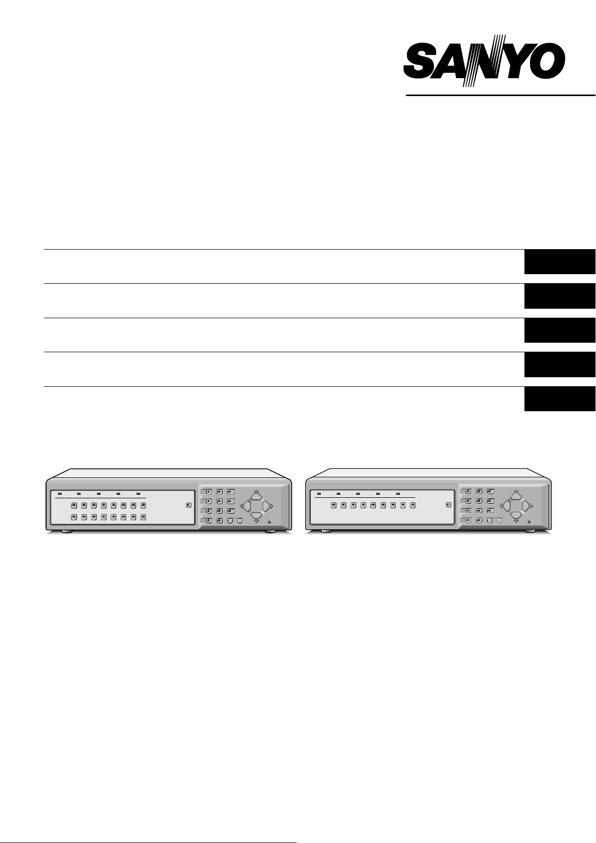
MPX-CD163P
MPX-CD93P
Multiplexer
Multiplexer
Multiplexeur
Multiplexor
Multi distributore
English GB
Deutsch D
Français F
Español E
Italiano I
(MPX-CD163P) (MPX-CD93P)
About this manual
Before installing and using this unit, please read this manual
•
carefully. Be sure to keep it handy for later reference.
This manual gives basic connections and operating
•
instructions for 2 models.
Über diese Anleitung
Lesen Sie bitte diese Bedienungsanleitung vor der
•
Installation und der Verwendung des Gerätes sorgfältig
durch. Bewahren Sie die Anleitung zum späteren
Nachschlagen auf.
In dieser Anleitung werden die Anschlüsse und die
•
Bedienungsanleitungen für 2 Modelle beschrieben.
À propos de ce manuel
Avant d’installer et d’utiliser cet appareil, veuillez lire ce
•
manuel attentivement. Assurez-vous de le garder à portée de
la main pour référence ultérieure.
Ce manuel couvre les instructions de branchement et
•
d’utilisation de base pour deux modèles.
Acerca de este manual
Antes de instalar y usar este aparato, lea detenidamente este
•
manual. Asegúrese de guardarlo a mano para futuras
referencias.
Este manual le indica las conexiones básicas y las
•
instrucciones de funcionamiento de dos modelos.
Nota su questo manuale
Leggere attentamente questo manuale prima di passare
•
all’installazione ed all’uso di questo apparecchio. Conservare
il manuale in un posto sicuro per riferimenti futuri.
Questo manuale contiene istruzioni per i principali
•
collegamenti ed il funzionamento di due modelli.
Page 2

PRECAUTION
WARNING: TO REDUCE THE RISK OF FIRE OR
ELECTRIC SHOCK, DO NOT EXPOSE THIS
APPLIANCE TO RAIN OR OTHER MOISTURE.
To avoid electrical shock, do not open the cabinet.
Refer servicing to qualified personnel only.
If the power supply cord (AC power cord) of this
appliance is damaged, it must be replaced. Return
to a SANYO Authorised Service Centre for
replacement of the cord.
Location
For safe operation and satisfactory performance of your
multiplexer, keep the following in mind when selecting a
place for its installation:
Shield it from direct sunlight and keep it away from sources
of intense heat.
Avoid dusty or humid places.
Avoid places with insufficient ventilation for proper heat
dissipation. Do not block the ventilation holes at the top and
bottom of the multiplexer. Do not place the unit on a carpet
because this will block the ventilation holes.
Install the multiplexer in a horizontal position only.
Avoid locations subject to strong vibrations.
Avoid moving the multiplexer between cold and hot
locations.
Do not place the multiplexer directly on top of a monitor TV,
as this may cause playback or recording problems.
Avoiding Electrical Shock and Fire
Do not handle the power cord with wet hands.
Do not pull on the power cord when disconnecting it from an
AC wall outlet. Grasp it by the plug.
If any liquid is spilled on the multiplexer, unplug the power
cord immediately and have the unit inspected at a
factory-authorised service centre.
Do not place anything directly on top of this multiplexer.
SERVICE
This unit is a precision instruments and if treated with care,
will provide years of satisfactory performance. However, in
the event of a problem, the owner is advised not to attempt
to make repairs or open the cabinet. Servicing should
always be referred to your dealer or Sanyo Authorized
Service Centre.
CAUTION
Danger of explosion if battery is incorrectly replaced.
Replace only with the same or equivalent type
recommended by the manufacturer.
Discard used batteries according to the manufacture’s
instructions.
English
– 1 –
Page 3

CONTENTS
MAIN FEATURES . . . . . . . . . . . . . . . . . . . . . . . . . . . . . . . . . . . . . . . . . . . . . . . . 4
ACCESSORIES . . . . . . . . . . . . . . . . . . . . . . . . . . . . . . . . . . . . . . . . . . . . . . . . . . 4
PART NAMES . . . . . . . . . . . . . . . . . . . . . . . . . . . . . . . . . . . . . . . . . . . . . . . . . . . 5
Front . . . . . . . . . . . . . . . . . . . . . . . . . . . . . . . . . . . . . . . . . . . . . . . . . . . . . . . .
Rear . . . . . . . . . . . . . . . . . . . . . . . . . . . . . . . . . . . . . . . . . . . . . . . . . . . . . . . . .
CONNECTIONS . . . . . . . . . . . . . . . . . . . . . . . . . . . . . . . . . . . . . . . . . . . . . . . . . . 8
Basic connections . . . . . . . . . . . . . . . . . . . . . . . . . . . . . . . . . . . . . . . . . . . . .
Connecting high image quality (S-VHS) video equipment. . . . . . . . . . . . .
Digital connections . . . . . . . . . . . . . . . . . . . . . . . . . . . . . . . . . . . . . . . . . . . .
System control connections. . . . . . . . . . . . . . . . . . . . . . . . . . . . . . . . . . . . .
Computer control. . . . . . . . . . . . . . . . . . . . . . . . . . . . . . . . . . . . . . . . . . . . . .
External alarm sensor setup. . . . . . . . . . . . . . . . . . . . . . . . . . . . . . . . . . . . .
Using as a monitor board during a motion sensor alarm . . . . . . . . . . . . .
Connecting a remote control circuit . . . . . . . . . . . . . . . . . . . . . . . . . . . . . .
11
11
12
12
12
MONITORING FUNCTIONS . . . . . . . . . . . . . . . . . . . . . . . . . . . . . . . . . . . . . . . . 13
VIEWING CAMERA IMAGES . . . . . . . . . . . . . . . . . . . . . . . . . . . . . . . . . . . . . . . 15
Viewing a single-screen image. . . . . . . . . . . . . . . . . . . . . . . . . . . . . . . . . . .
Viewing multiple-screen images. . . . . . . . . . . . . . . . . . . . . . . . . . . . . . . . . .
Viewing automatically switching images. . . . . . . . . . . . . . . . . . . . . . . . . . .
15
18
20
5
7
8
8
9
VIEWING RECORDED IMAGES . . . . . . . . . . . . . . . . . . . . . . . . . . . . . . . . . . . . . 23
Playing back recorded images in a single-screen display. . . . . . . . . . . . .
Playing back multiple-screen displays . . . . . . . . . . . . . . . . . . . . . . . . . . . .
Playing back automatically switching images . . . . . . . . . . . . . . . . . . . . . .
23
25
27
VIEWING WITH SPOT MONITOR . . . . . . . . . . . . . . . . . . . . . . . . . . . . . . . . . . . . 29
Spot Monitor Button Functions . . . . . . . . . . . . . . . . . . . . . . . . . . . . . . . . . .
Spot monitor settings . . . . . . . . . . . . . . . . . . . . . . . . . . . . . . . . . . . . . . . . . .
29
30
MENU FLOWCHART AND MENU OPERATIONS . . . . . . . . . . . . . . . . . . . . . . . 31
Menu flowchart. . . . . . . . . . . . . . . . . . . . . . . . . . . . . . . . . . . . . . . . . . . . . . . .
Menu operations . . . . . . . . . . . . . . . . . . . . . . . . . . . . . . . . . . . . . . . . . . . . . .
31
32
LANGUAGE SETTING. . . . . . . . . . . . . . . . . . . . . . . . . . . . . . . . . . . . . . . . . . . . . 33
LANGUAGE screen display. . . . . . . . . . . . . . . . . . . . . . . . . . . . . . . . . . . . . .
33
CLOCK SET SETTINGS . . . . . . . . . . . . . . . . . . . . . . . . . . . . . . . . . . . . . . . . . . . 34
Clock settings. . . . . . . . . . . . . . . . . . . . . . . . . . . . . . . . . . . . . . . . . . . . . . . . .
TIMER settings . . . . . . . . . . . . . . . . . . . . . . . . . . . . . . . . . . . . . . . . . . . . . . . .
SUMMER TIME setting. . . . . . . . . . . . . . . . . . . . . . . . . . . . . . . . . . . . . . . . . .
35
36
38
– 2 –
English
Page 4

CONTENTS
DISPLAY SET SETTINGS . . . . . . . . . . . . . . . . . . . . . . . . . . . . . . . . . . . . . . . . . . 39
TITLE setting . . . . . . . . . . . . . . . . . . . . . . . . . . . . . . . . . . . . . . . . . . . . . . . . .
MULTI SCREEN setting . . . . . . . . . . . . . . . . . . . . . . . . . . . . . . . . . . . . . . . . .
SEQUENCE setting . . . . . . . . . . . . . . . . . . . . . . . . . . . . . . . . . . . . . . . . . . . .
MASK settings . . . . . . . . . . . . . . . . . . . . . . . . . . . . . . . . . . . . . . . . . . . . . . . .
MAIN → SPOT 1 setting. . . . . . . . . . . . . . . . . . . . . . . . . . . . . . . . . . . . . . . . .
DIGITAL CONNECTION settings. . . . . . . . . . . . . . . . . . . . . . . . . . . . . . . . . .
COLOR LEVEL settings. . . . . . . . . . . . . . . . . . . . . . . . . . . . . . . . . . . . . . . . .
40
41
43
47
49
50
50
VCR SET SETTINGS . . . . . . . . . . . . . . . . . . . . . . . . . . . . . . . . . . . . . . . . . . . . . . 52
VCR SET settings. . . . . . . . . . . . . . . . . . . . . . . . . . . . . . . . . . . . . . . . . . . . . .
PROGRAM REC. setting . . . . . . . . . . . . . . . . . . . . . . . . . . . . . . . . . . . . . . . .
53
56
ALARM SET SETTINGS . . . . . . . . . . . . . . . . . . . . . . . . . . . . . . . . . . . . . . . . . . . 59
ALARM SET settings . . . . . . . . . . . . . . . . . . . . . . . . . . . . . . . . . . . . . . . . . . .
ALARM DISPLAY setting. . . . . . . . . . . . . . . . . . . . . . . . . . . . . . . . . . . . . . . .
SPOT MONITOR SET setting . . . . . . . . . . . . . . . . . . . . . . . . . . . . . . . . . . . .
ACTIVE REC setting . . . . . . . . . . . . . . . . . . . . . . . . . . . . . . . . . . . . . . . . . . .
MOTION SENSOR setting . . . . . . . . . . . . . . . . . . . . . . . . . . . . . . . . . . . . . . .
61
63
63
64
67
VIDEO LOSS setting . . . . . . . . . . . . . . . . . . . . . . . . . . . . . . . . . . . . . . . . . . .
Resetting an alarm. . . . . . . . . . . . . . . . . . . . . . . . . . . . . . . . . . . . . . . . . . . . .
68
69
SECURITY SET SETTINGS. . . . . . . . . . . . . . . . . . . . . . . . . . . . . . . . . . . . . . . . . 70
To set SECURITY LOCK for all operating buttons . . . . . . . . . . . . . . . . . . .
SETUP setting . . . . . . . . . . . . . . . . . . . . . . . . . . . . . . . . . . . . . . . . . . . . . . . .
70
71
CONTROL SET SETTINGS . . . . . . . . . . . . . . . . . . . . . . . . . . . . . . . . . . . . . . . . . 72
CONTROL SET settings. . . . . . . . . . . . . . . . . . . . . . . . . . . . . . . . . . . . . . . . .
CAMERA CONTROL setting . . . . . . . . . . . . . . . . . . . . . . . . . . . . . . . . . . . . .
72
73
ALARM DATA SETTINGS. . . . . . . . . . . . . . . . . . . . . . . . . . . . . . . . . . . . . . . . . . 74
Displaying the alarm data list . . . . . . . . . . . . . . . . . . . . . . . . . . . . . . . . . . . .
74
INTERFACE SPECIFICATIONS . . . . . . . . . . . . . . . . . . . . . . . . . . . . . . . . . . . . . 75
SPECIFICATIONS . . . . . . . . . . . . . . . . . . . . . . . . . . . . . . . . . . . . . . . . . . . . . . . . 80
English
– 3 –
Page 5

MAIN FEATURES
This multiplexer can display images that are being recorded
by a camera in a split-screen (16, 9, 4), and it can also
display images that have already been recorded in a
split-screen.
The MPX-CD93P model split-screen display is capable of
4-screen or 9-screen displays only.
High-speed switching for each field at maximum speed
•
Single-screen, 4-screen, 9-screen and 16-screen
•
display, camera images and video playback images can
be displayed in the lower-right corner of the screen, and
automatic switching is also possible.
Multiple multiplexers can be connected together to
•
create an expanded system for centralized monitoring.
A single-screen can be displayed during spot monitoring
•
and the alarm screen can be displayed when an alarm
occurs.
Timer setting allows the following settings to be made for
•
each camera.
– Program recording lets images from a specified
camera be recorded during four different daily time
zones.
– Automatic switching of camera images selected by
timer period
– Setting of automatic screen switching speed for each
camera for four different daily time zones.
A monitor masking function hides the images for
•
specified cameras with gray patterns so that they cannot
be monitored.
Motion sensor detection is possible for each camera.
•
Moving objects can be given recording priority and alarm
operation is possible.
If a signal loss is detected, the monitor screen image can
•
be replaced by a test pattern or a still image, even if the
camera image has been lost as a result of the
interruption.
Cameras that can be controlled via coaxial cables can
•
be connected to allow operation of these cameras from
the multiplexer.
Computer control via an RS-232C interface is possible.
•
Connection to a system controller (sold separately) is
•
possible using an RS-485 (RJ-11) interface.
Equipped with four spot monitor outputs and S-Video
•
signal input and output connectors.
Menu screens allow the display of up to 100 alarm
•
recording items.
Connection to digital equipment such as a digital video
•
recorder (sold separately) is possible using digital
connectors.
ACCESSORIES
Power cord x1
Power cord tie x1
– 4 –
English
Page 6
PART NAMES
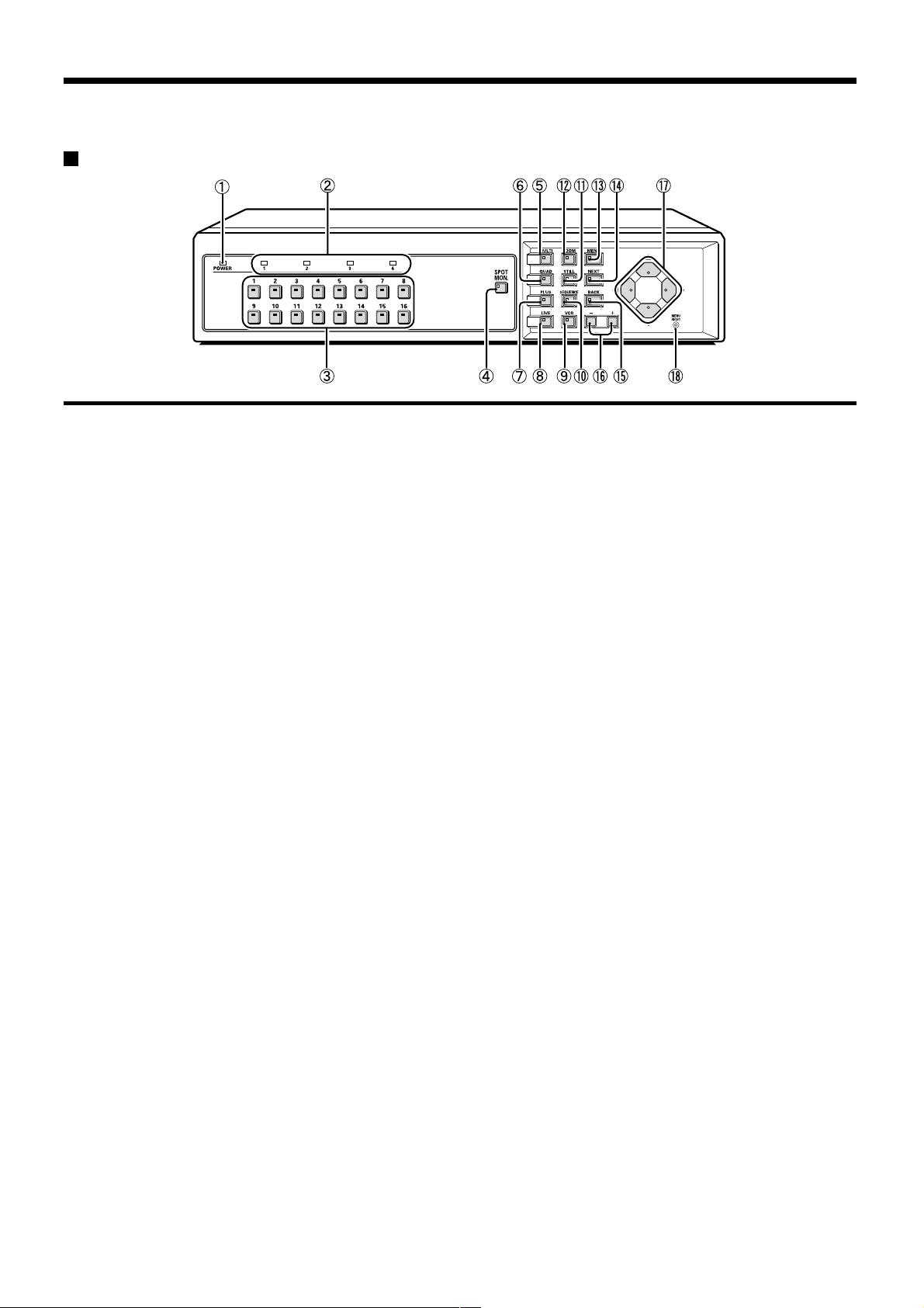
Front
(MPX-CD163P)
1 POWER indicator (POWER)
Illuminates when the power cord plug is inserted into a
wall outlet.
2 Spot monitor indicators
When spot monitoring has been set, the indicator for
the specified monitor illuminates. (See page 29.)
3 Camera select buttons and indicators
When a camera is connected to one of the camera
video input (CAMERA IN) connectors at the rear of the
multiplexer and the corresponding button is pressed,
the indicator illuminates and images from that camera
are displayed.
(Indicators)
During split-screen monitoring, the indicators for all of
•
the cameras being displayed in the split-screen
illuminate.
When there is alarm input, the indicator for the alarm
•
input camera flashes.
When spot monitoring operation has been set, the
•
indicator for the specified monitor illuminates.
4 Spot monitor button and indicator (SPOT MON.)
This button is used to set spot monitoring.
(See page 29.)
5 Multiple display button and indicator (MULTI)
This button lets you switch the display to a 16-screen
display or 9-screen display while monitoring is being
carried out using the single-screen or 4-screen display.
When the MULTI button is pressed, the 9-screen
display or 16-screen display appears, and the
split-screen display then changes each time the button
is pressed again. The indicator illuminates, but turns off
when any other screen switching operations are carried
out.
The split-screen display positions can be rearranged
•
using the menu screen. (See page 41.)
For the MPX-CD93P model, a 9-screen display will
•
appear. The 16-screen display is not available.
6 4-screen display button and indicator (QUAD)
This button lets you switch the display to a 4-screen
display while monitoring is being carried out using a
single-screen display, 16-screen display or 9-screen
display.
When the QUAD button is pressed, the screen
switches to 4-screen display, and the 4-screen display
changes (1 – 4, 5 – 8, 9 – 12, 13 – 16) each time the
QUAD button is then pressed. The indicator illuminates
to match the 4-screen display.
For the MPX-CD93P model, the 4-screen display
•
changes each time the QUAD button is pressed
(1 – 4, 5 – 8, 9 – 3).
The split-screen display position can be rearranged
•
using the menu screen. (See page 41.)
7 Plus display button and indicator (PLUS)
This button lets you display a specified image in the
lower-right quarter of the screen area while monitoring
is being carried out using a 16-screen display or
9-screen display (6-screen display or 13-screen
display).
When the PLUS button is pressed, the lower-right
quarter of the screen is displayed as a single screen
area, and the indicator flashes. If you press the camera
select button for the image required, that image
appears in the quarter screen. The following operations
can be carried out when this quarter screen is being
displayed.
If the MULTI button is pressed, the screen changes
•
to a 6-screen display or 13-screen display. The
image in the quarter screen remains unchanged.
(For the MPX-CD93P model, only the 6-screen
display is available.)
If the SEQUENCE button is pressed, the
•
SEQUENCE indicator flashes and the quarter screen
automatically changes. The automatic screen
switching speed can be set using the menu screen.
(See page 43.)
8 Live image button and indicator (LIVE)
Press this button to view camera images. The indicator
will illuminate and the camera images will appear on
the monitor.
English
– 5 –
Page 7
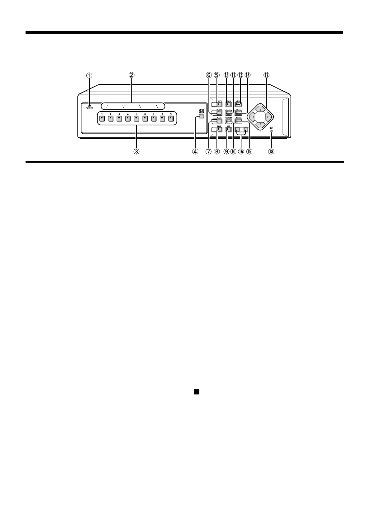
PART NAMES
(MPX-CD93P)
9 Video playback button and indicator (VCR)
Press this button to play back recorded images. The
indicator will illuminate and the video playback images
will appear on the monitor.
F Automatic camera switching button and indicator
(SEQUENCE)
This button is used to automatically change the camera
image appearing in the single-screen, 4-screen or
quarter screen (plus screen) display.
When the SEQUENCE button is pressed, the indicator
flashes and the screen changes automatically. The
camera indicator also changes to match the images on
the screen.
G Still image button and indicator (STILL)
If this button is pressed while monitoring is being carried
out using the single-screen display, the indicator will flash
and the image will be paused. If the button is pressed
once more, the image returns to normal.
H Electronic zoom button and indicator (ZOOM)
If monitoring is being carried out using the
single-screen display, the image can be enlarged by
2x. When this button is pressed, the indicator will flash
and the 2x zoom screen will be displayed.
I Menu button and indicator (MENU)
This button is used to display the menu screen.
J Next screen button and indicator (NEXT)
If this button is pressed while a menu screen is displayed, a
•
sub-menu setting screen is displayed.
If a camera that can be controlled via a coaxial cable (such
•
as a dome-type camera) is connected, this button can be
used for one-touch focus adjustment. Playback of recorded
images from multiple digital video recorders is carried out
by selecting the images at the digital video recorders.
K Cancel/display button and indicator (BACK)
If this button is pressed while a sub-menu screen is displayed,
•
the screen returns to the previous level menu screen.
If this button is pressed while monitoring camera images, the
•
on-screen displays (such as titles) can be turned on and off.
L Setting buttons (+, –)
These buttons are used to change the setting values in the
•
menu screens (setting screens).
If a coaxial cable camera (such as a dome-type camera) is
•
connected, these buttons can be used to carry out zoom
operation.
Furthermore, if these buttons are pressed after a camera
select button, manual focus adjustment is possible. They
can also be used to adjust the playback speed when
recorded images from a digital video recorder are being
played back.
M Cursor buttons
These buttons can be used to select items while a menu
•
screen (setting screen) is displayed.
If a camera that can be controlled via a coaxial cable (such
•
as a dome-type camera) is connected, these buttons can
be used to carry out pan and tilt operations.
Furthermore, if these buttons are pressed after a camera
select button, iris adjustment is possible.
They can also be used to carry out playback, stop, pause
•
and reverse operations when recorded images from a
digital video recorder are being played back.
N Menu reset/Clock adjust button (MENU RESET)
If this button is pressed while a menu screen (setting
screen) is displayed, the settings in the
currently-displayed menu screen are reset to their
default values.
If this button is pressed while monitoring camera
images, the clock is adjusted and the minutes and
seconds are reset to 00.
About the cooling fan
In order to keep the unit internal temperature low, a fan is
provided on the side of the unit. If the fan does not operate
properly, the POWER indicator will flash to indicate a
problem. Unplug the unit from the power supply and check
to make sure nothing is obstructing the fan. If after the
power is restored to the unit, the POWER indicator still
flashes, do not use the unit and consult your dealer.
– 6 –
English
Page 8
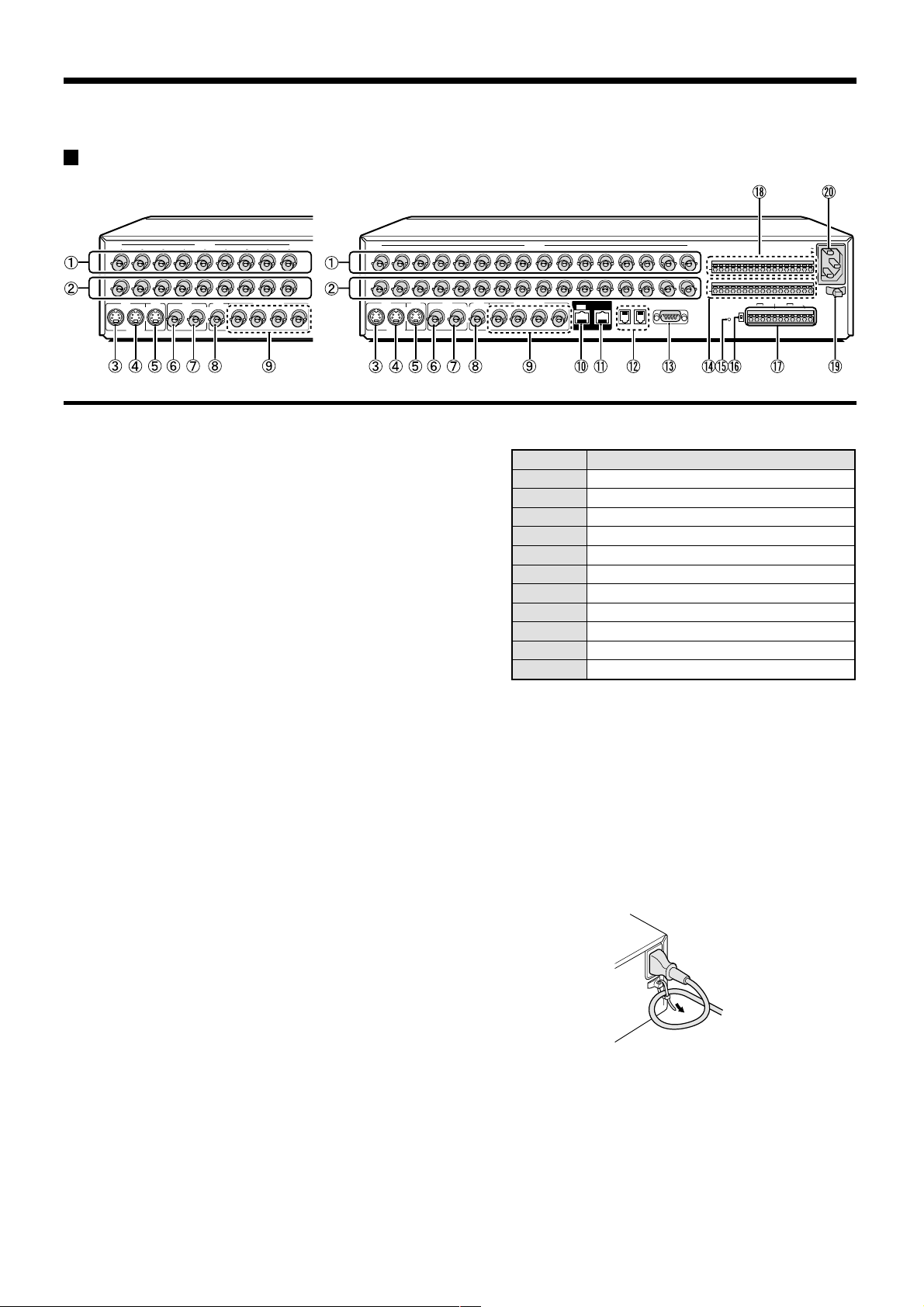
PART NAMES
Rear
(MPX-CD93P) (MPX-CD163P)
1234567 98
IN
OUT
VCR
IN
OUT
MONITOR
S-VIDEO
CAMERA
MAIN
MAIN
VCR
IN
MONITOR
SPOT MONITOR
21OUT
34
123
IN
OUT
VCR
OUT
IN
S-VIDEO
MAIN
MONITOR
1 Camera video input connectors (CAMERA IN 1 – 16)
Connect to the output connectors of the monitoring
cameras.
The MPX-CD93P model has nine input connectors.
2 Camera video output connectors (CAMERA OUT 1 – 16)
These are pass-through connectors that output camera
images to an external monitor.
The MPX-CD93P model has nine output connectors.
3 VCR S-Video input connector (S-VIDEO VCR IN)
4 VCR S-Video output connector (S-VIDEO VCR OUT)
5 Main monitor S-Video output connector (MAIN
MONITOR S-VIDEO OUT)
6 VCR input connector (VCR IN)
7 VCR output connector (VCR OUT)
8 Main monitor output connector (MAIN MONITOR)
9 Spot monitor output connectors (SPOT MONITOR 1 – 4)
4 5 6 7 9 101112131415168
MAIN
VCR
MONITOR
IN
1OUT
M Control connector (CONTROL)
N Alarm input connectors (ALARM IN 1 – 16)
CAMERA
SPOT MONITOR
2
34 A
DIGITAL
OUT
RS485
B
RS232C
DO NOT CONNECT TO PHONE LINE
ALARM IN
C
12345678910IN11 12 13 14 15 16
SENSOR
ALARM OUT
RS485
TERMINATE
C
ON
ALL
RESET
OFF
S
W
RS485
ALARM OUT REMOTE
A B C C R1 R2 C C
CONTROL
AC IN
I
N
Pin Signal
C Ground
A RS-485 connector*
B RS-485 connector*
C Ground
AL Alarm output (DC 5V)
C Ground
R1 Remote control input 1
R2 Remote control input 2
C Ground
SW Switch input (DC 5V)
C Ground
* Used for twisted-pair cable connection.
If external alarm switches that are connected to these
connectors are turned on or off, an alarm is output from
the AL pin of the control connector.
The MPX-CD93P model has nine alarm input
connectors.
F Digital input connector (DIGITAL IN)
G Digital output connector (DIGITAL OUT)
H RS-485 control connectors (RS485 A/B)
I RS-232C connector (RS232C)
This connector can be connected to the RS232C
connector of a computer using a D-Sub 9-pin cable
(sold separately) so that control of the multiplexer can
be carried out by the computer.
J Sensor alarm output connector
(SENSOR ALARM OUT)
Outputs alarm signals when a camera that is
connected to one of the CAMERA IN connectors
receives a sensor alarm.
The MPX-CD93P model has nine alarm output
connectors.
K All reset button (ALL RESET)
L RS-485 termination switch (RS485 TERMINATE)
English
O Power cord holder
Secure the power cord to the holder using the
accessory power cord tie as shown in the illustration.
P Power socket (AC IN~)
Securely insert the accessory power cord into the
power socket, and insert the power cord plug into a wall
outlet. When the power cord is inserted into the wall
outlet, the POWER indicator and other indicators will
illuminate.
– 7 –
Page 9
CONNECTIONS
Turn off the power for all components before connecting them.
Be sure to carefully read the Instruction Manual for all equipment being connected to the multiplexer.
If the connections are incorrect, smoke or operating malfunctions may result.
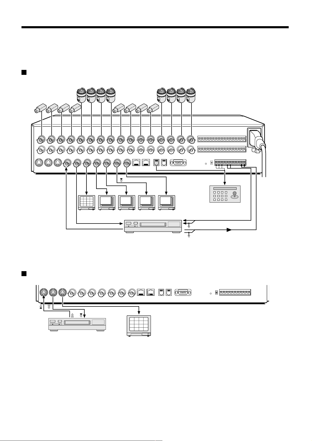
Basic connections (MPX-CD163P model)
Nine cameras can be connected to the MPX-CD93P model.
VIDEO IN connector
2
1
3
4
6
5
7
8
10
9
11
12
14
13
15
16
TV monitor (sold separately)
RS-485 connector
System controller (sold separately)
ALARM IN connector
Ground (C)
Time lapse VCR (sold separately)
Ground (C)
Switch output connector
Connecting high image quality (S-VHS) video equipment
S-VIDEO OUT connector S-VIDEO IN connector
Time lapse VCR (sold separately)
S-VIDEO IN connector
4
3
1
2
8
7
5
6
12
11
9
10
16
15
13
14
– 8 –
English
Page 10
CONNECTIONS
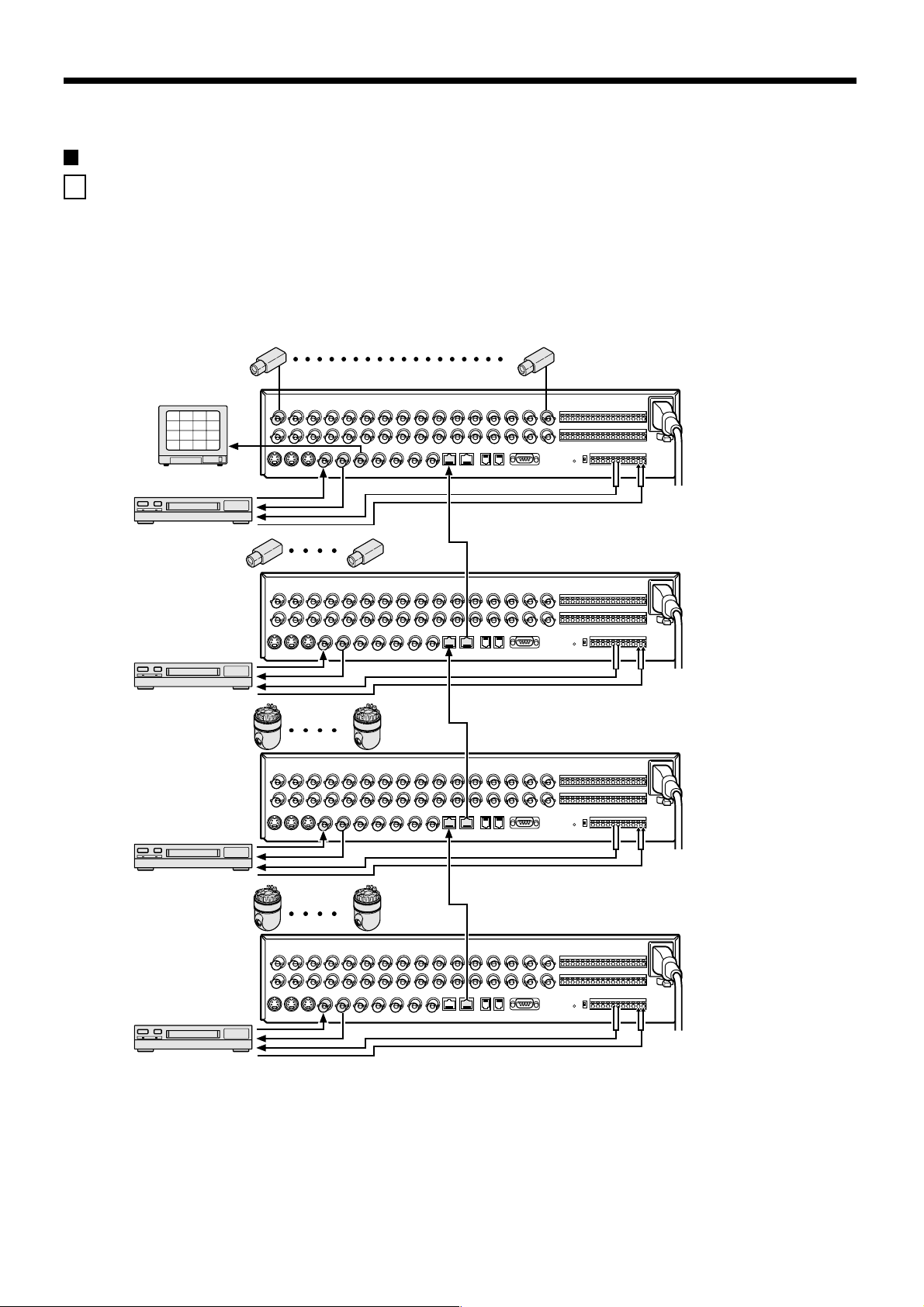
Digital connections
A Connecting four multiplexers digitally
Up to four of these units can be connected for monitoring.
By connecting several units, up to 64 cameras can be viewed with one main monitor. Also, by connecting a recorder to each
multiplexer, playback of recorded images can be viewed on the main monitor.
* For the MPX-CD93P model, the total number of cameras that can be viewed with one monitor is 36, nine to each unit.
Use straight-type CAT-5 RS485 cables (sold separately) to connect the DIGITAL IN connectors to the digital output connectors
of other devices.
Use cables with a length of 3 m or less.
1 – 16
Main monitor
2
1
3
4
6
5
7
8
10
9
11
12
14
13
15
16
Main multiplexer
TV monitor
(sold separately)
Time lapse VCR
(sold separately)
Time lapse VCR
(sold separately)
Time lapse VCR
(sold separately)
17 – 32
33 – 48
49 – 64
DIGITAL IN
✱ Cable (straight-type CAT-5, 3 m or less)
DIGITAL OUT
Sub 1
DIGITAL IN
DIGITAL OUT
Sub 2
DIGITAL IN
DIGITAL OUT
Sub 3
Time lapse VCR
(sold separately)
Note: (Main unit and sub-units)
Main unit and sub-units must be specified. Distinguishing a main unit and sub-units enables the main unit to display the
•
camera images of a sub-unit on the monitor. (See page 50.)
Since no video signal is output from the main monitor output connector on the rear panel of a sub-unit, if a monitor is
•
connected the screen will be black.
If these connections have been made, a digital video recorder cannot be connected digitally.
•
English
– 9 –
Page 11

CONNECTIONS
B Connecting the multiplexer and a digital video recorder digitally
This unit and a digital video recorder can be connected digitally to provide high-resolution playback of recorded images.
Use straight-type CAT-5 RS485 cables (sold separately) to connect the DIGITAL IN connectors to the digital output connectors
of other devices.
Use cables with a length of 3 m or less.
1 – 16
Main monitor
2
1
3
4
6
5
7
8
10
9
11
12
14
13
15
16
TV monitor (sold separately)
DIGITAL
DIGITAL OUT
IN
Main multiplexer
Time lapse VCR (sold separately)
Digital video recorder (sold separately)
✱ Cable
(straight-type CAT-5, 3 m or less)
DIGITAL OUTDIGITAL IN
ALARM IN
connector
Ground (C)
– 10 –
English
Page 12
CONNECTIONS
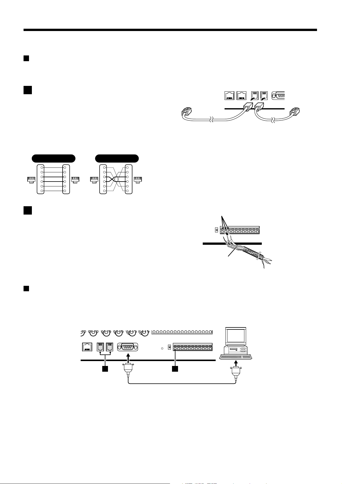
System control connections
Use the RS485 connector or the CONTROL connector to connect a system controller to the multiplexer. After connecting the
system controller, you will need to carry out the settings that are given in the CONTROL SET menu. (See page 72.)
A When using the RS485 (RJ-11) connector
Connect modular cables (sold separately) to the RS485
control connectors at the rear of the multiplexer.
• If using a straight-type cable
Connect connector A to connector A and connector B to
connector B.
• If using a cross-type cable
Connect connector A to connector B and connector B to
connector A.
Straight type Cross type
Spare
1
Spare
2
61616116
3
4
Spare
5
Spare
6
1
2
3
4
5
6
Spare
1
Spare
2
3
4
5
Spare
6
Spare
1
2
3
4
5
6
To other
connector A
Straight-type cable Cross-type cable
To other
connector A
B When using the CONTROL connector (A/B)
Push the cable in.
Connect a twisted-pair cable (sold separately) to the A, B
and C (ground) terminals of the CONTROL connector at the
rear of the multiplexer. Connect signal A to signal A and
signal B to signal B.
Twisted-pair cable
Ground
To signal B
To signal A
Computer control
When connecting the multiplexer to a computer (sold separately), use a D-Sub 9-pin cable (sold separately) to connect the
RS-232C connector to the computer. After connecting, you will need to carry out the settings that are given in the CONTROL
SET menu. (See page 72.)
Computer
A B
English
– 11 –
Page 13
CONNECTIONS
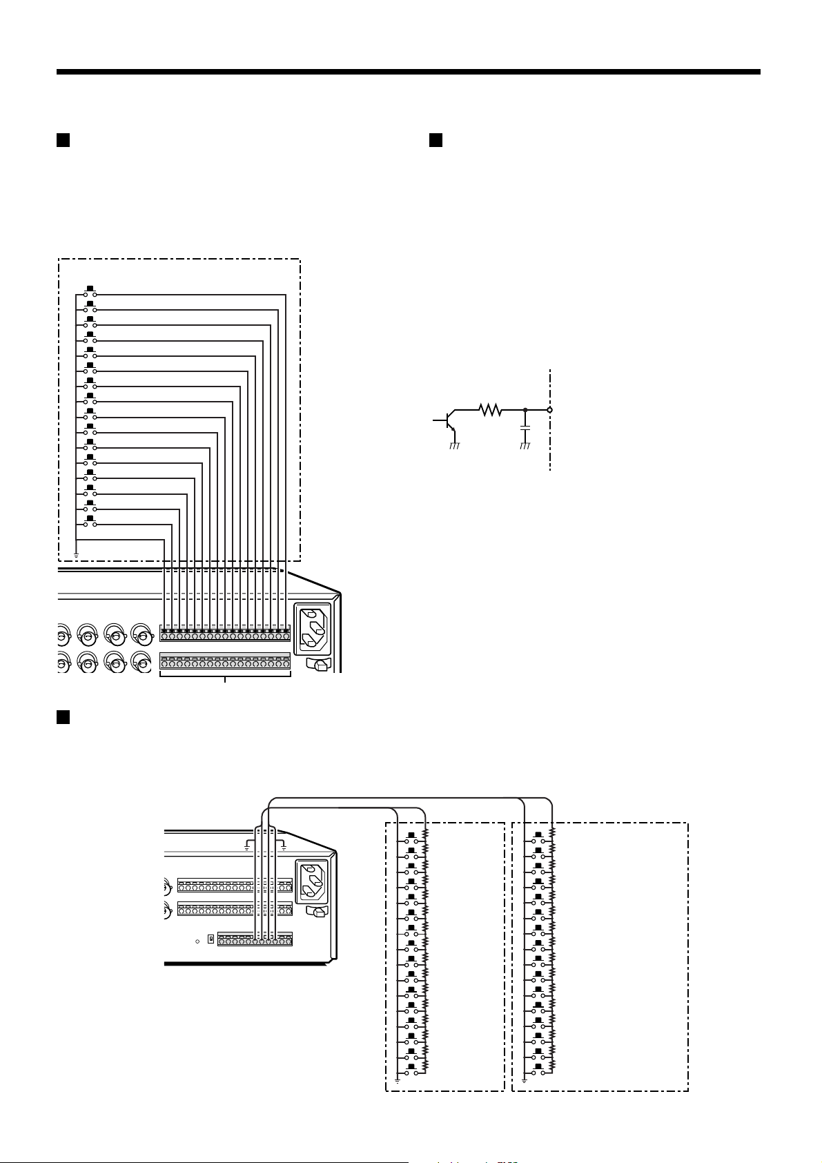
External alarm sensor setup
In order to make an external alarm sensor operate, an
external switch must be connected to an ALARM IN
connector. When an intruder activates the external switch
(such as by opening a door), an alarm signal is received
and an alarm can be made to sound.
The MPX-CD93P model uses the connectors marked *.
Connect an external switch
to an ALARM IN connector
*
*
*
*
*
*
*
*
*
Using as a monitor board during
a motion sensor alarm
When the motion sensor built into the multiplexer responds
to an alarm, it outputs an alarm signal to the SENSOR
ALARM OUT connector. If a switching circuit such as a
warning lamp is connected to this connector, the warning
lamp will illuminate when there is a response from the
motion sensor. If the warning lamp is fixed somewhere in
the layout diagram for an area such as a factory, the
location of the camera can be ascertained in an instant
during an emergency. The connector is always open. The
pin corresponding to the number of the camera that
generates a sensor response switches to Low.
1K
Rated values for each connector (at 25˚C)
• Max. current
• Max. voltage
• Max. power
25mA
25V
40mW
SENSOR ALARM OUT connector
Connecting a remote control circuit
If a remote control circuit is constructed as shown in the illustration and connected to the remote control input (R1 and R2)
terminals of the CONTROL connector, the multiplexer can be operated by remote control. (Contact LOW input)
The MPX-CD93P model can control up to nine cameras.
R1 R2
220Ω
SW 17: Menu selection
220Ω
SW 18: Video playback
300Ω
SW 19: Live image
360Ω
SW 20: Multi display
470Ω
SW 21: Plus display
680Ω
SW 22: Auto camera switching
820Ω
SW 23: Electronic zoom
1.2kΩ
SW 24: Still image
1.8kΩ
SW 25: Spot monitor
2.2kΩ
SW 26: 4-screen display
3.3kΩ
SW 27: Next
4.7kΩ
SW 28: Previous
7.5kΩ
SW 29: +
13kΩ
SW 30: –
27k
SW 31: 3
68kΩ
SW 32: 2
SW: Switch
Note:
The remote control cable should
be no more than 5 m long.
220Ω
SW 1: Camera1
220Ω
SW 2: Camera2
300Ω
SW 3: Camera3
360Ω
SW 4: Camera4
470Ω
SW 5: Camera5
680Ω
SW 6: Camera6
820Ω
SW 7: Camera7
1.2kΩ
SW 8: Camera8
1.8kΩ
SW 9 : Camera9
2.2kΩ
SW 10 : Camera10
3.3kΩ
SW 11 : Camera11
4.7kΩ
SW 12 : Camera12
7.5kΩ
SW 13 : Camera13
13kΩ
SW 14 : Camera14
27kΩ
SW 15 : Camera15
68kΩ
SW 16 : Camera16
– 12 –
English
Page 14
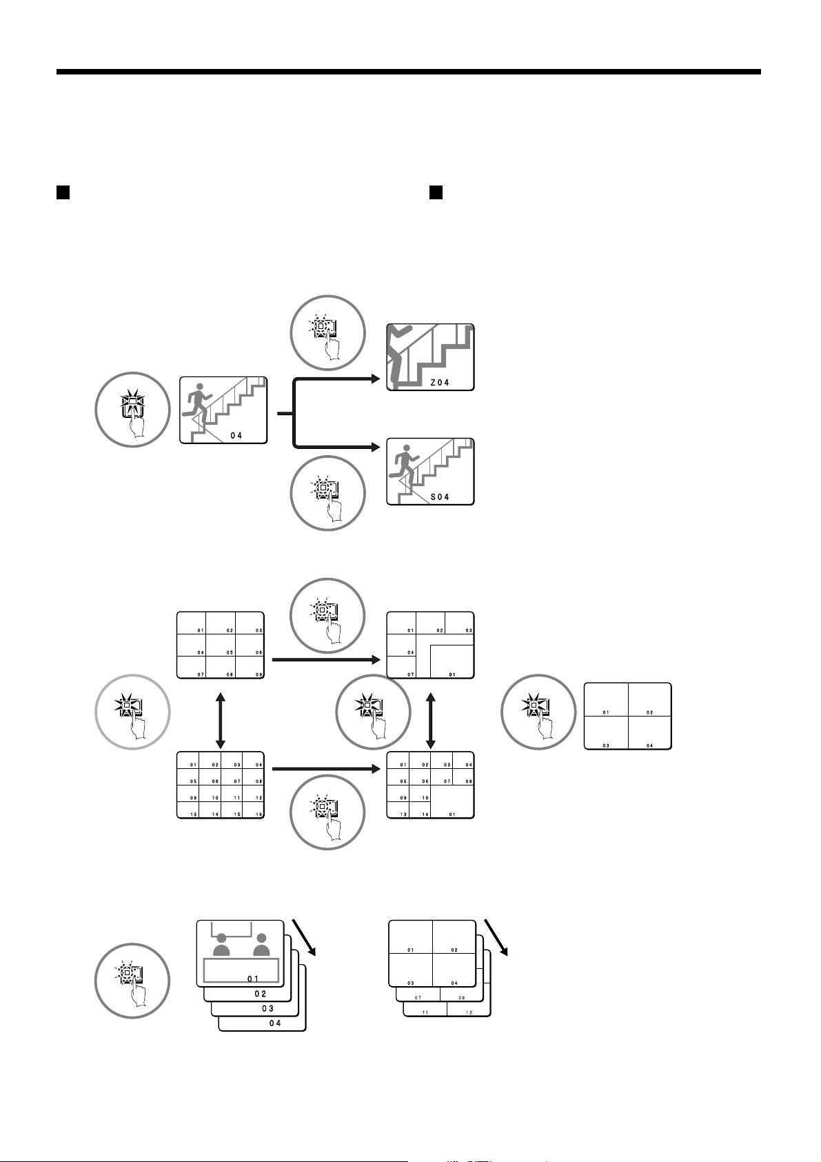
MONITORING FUNCTIONS
Following is a summary of the operations that can be carried out while monitoring camera images. Refer to the corresponding
page numbers for more detailed explanations.
Viewing camera images
(See page 15.)
Viewing recorded images
(See page 23.)
The following operations can be carried out while monitoring camera images and when playing back images that have been
recorded.
◆ Viewing a single-screen image (See page 15.)
ZOOM
4
Single-screen
STILL
Zoom
Still image
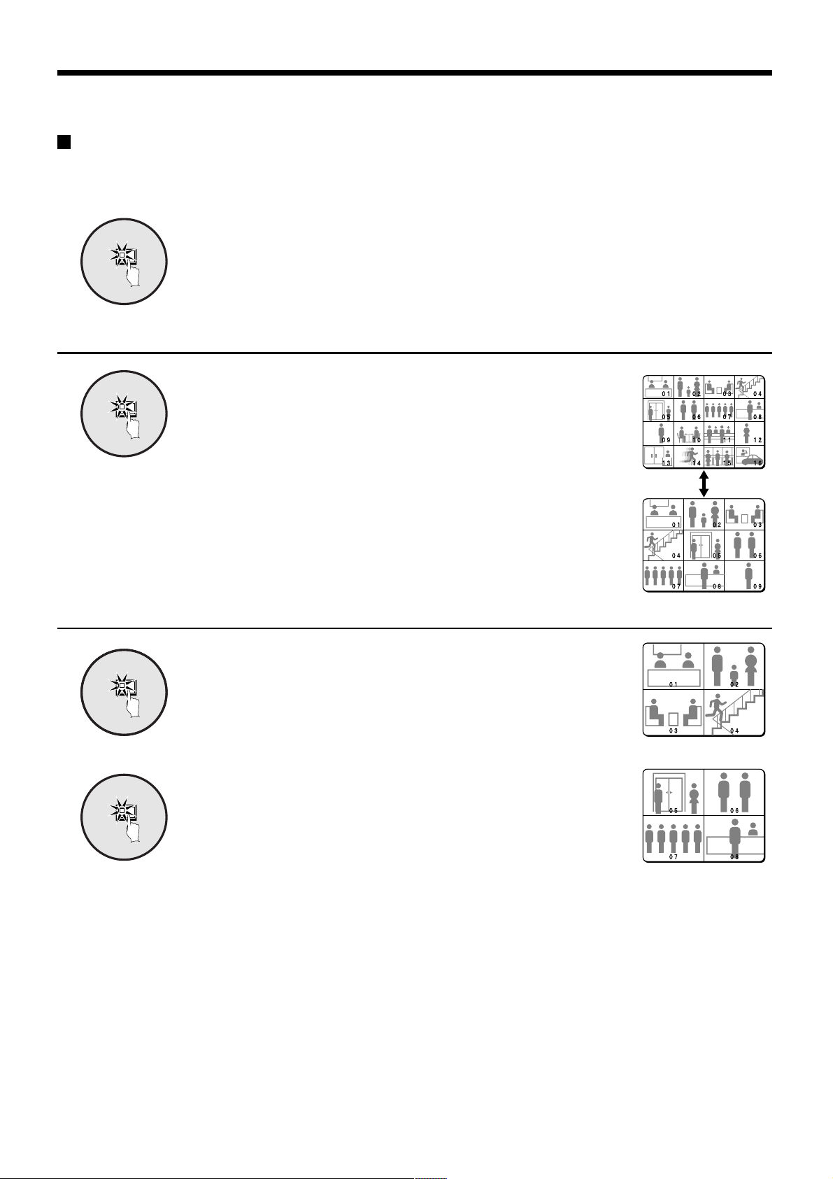
◆ Viewing multiple-screen images (See page 18.)
PLUS
9-screen display
16-screen display
MULTIMULTI
PLUS
6-screen display
13-screen display
For the MPX-CD93P model, a 9-screen display will appear.
◆ Viewing automatically switching images (See page 20.)
SEQUENCE
QUAD
4-screen display
English
Automatic switching of
single-screen display
Automatic switching of
4-screen display
– 13 –
Page 15
MONITORING FUNCTIONS
VIDEO LOSS
VIDEO LOSS
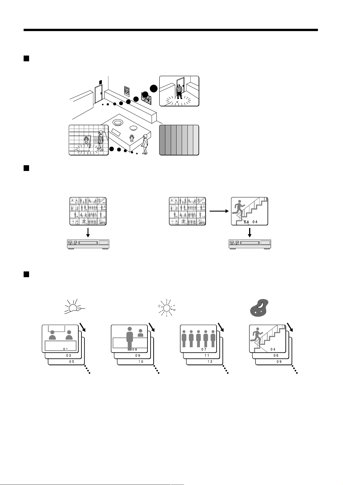
Alarm function
Suspicious people can be detected while monitoring by using the alarm setting function. (See page 60.)
External alarm sensor
Motion sensor alarm
(See page 67.)
A A
A A
CAMERA 4
CAMERA 1
VIDEO LOSSVIDEO LOSS
External alarm (See page 12.)
Signal loss detection alarm
(See page 68.)
Recording function
A video recording device can be used to record camera images and alarm images taken during monitoring.
Program recording (See page 56.) Active recording (See page 64.)
VCR
Monitor
Monitor
VCR
Monitor
Records camera images Recording priority is given to alarm images.
Timer function
By using the timer function, a single day can be divided into four different time and each camera can be operated separately
during each time zone.
Morning Afternoon Night
Timer 1 Timer 2 Timer 3 Timer 4
6:00 – 11:00 11:00 – 13:00 13:00 – 18:00 18:00 – 6:00
Images from cameras
1, 3, 5 and 6 are
switched automatically
Images from cameras
8, 9, 10 and 16 are
switched automatically
Automatic switching display and recording of different camera images can be specified for each time zone.
Furthermore, if sensor alarms are set, intruders can be detected during those time zones.
Timer setting (See page 36.)
•
Using the timer function for automatic switching display (See page 45.)
•
Using the timer function to record images (See page 58.)
•
Using the timer function to detect motion alarms (See page 67.)
•
Using the timer function to cover the camera image with a gray pattern (See page 48.)
•
Images from cameras
7, 11, 12 and 13 are
switched automatically
Images from cameras
4, 6, 9, 12 and 16 are
switched automatically
– 14 –
English
Page 16
VIEWING CAMERA IMAGES
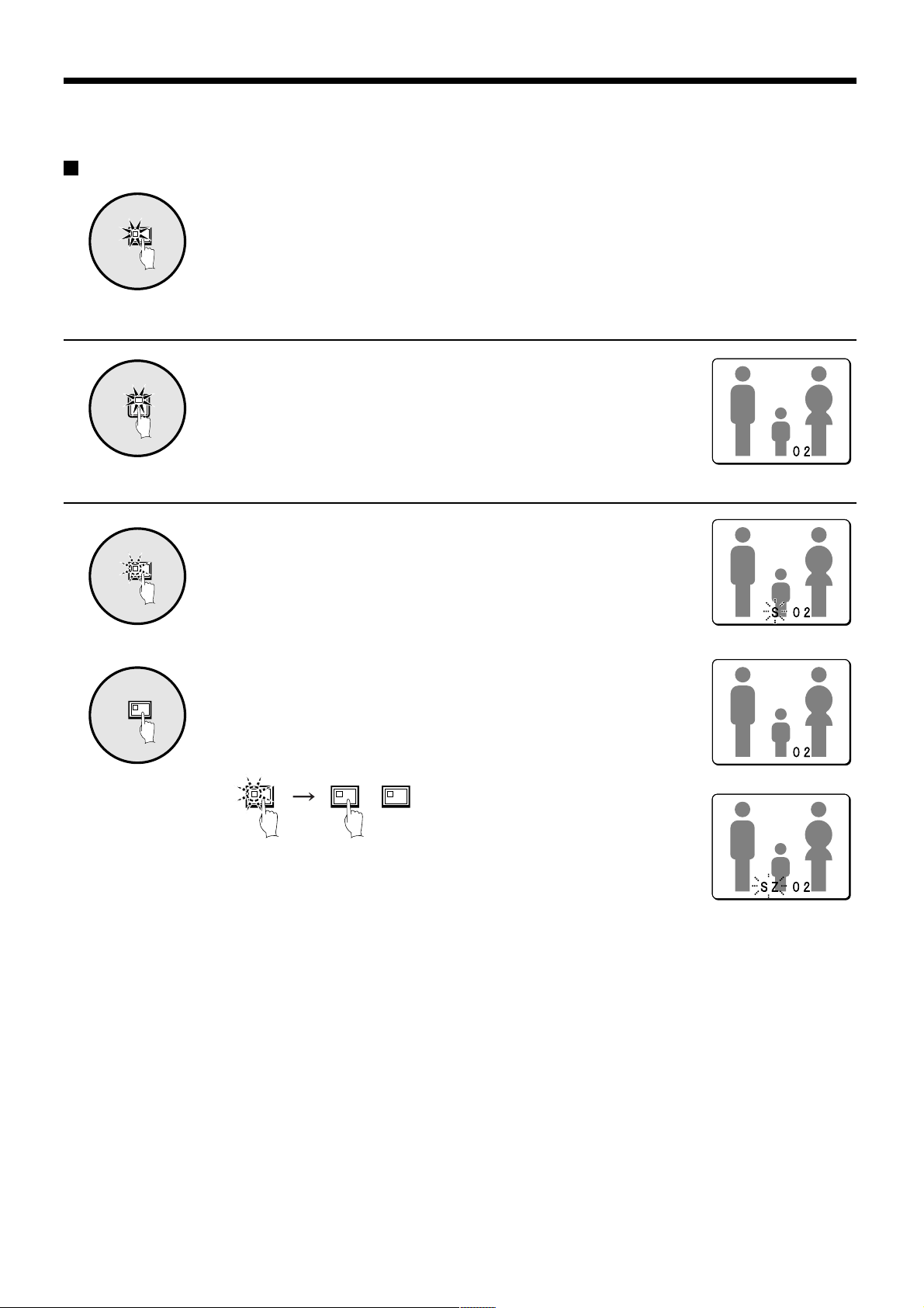
Viewing a single-screen image
Press the LIVE button.
LIVE
Setting the camera image to single-screen display
2
Pausing images
The camera image appears as a split-screen.
Press a camera select button (example: 2).
The camera 2 image appears as a single-screen.
1
STILL
2
STILL
Press the STILL button.
The image will be paused.
To cancel the still image, press the STILL button once more.
Pausing will be canceled and normal images will appear.
Note: If you press the ZOOM button while the image is paused, the still
image will be enlarged. To return to the original still image, press
the ZOOM button once more.
STILL STILLZOOM
English
– 15 –
Page 17

VIEWING CAMERA IMAGES
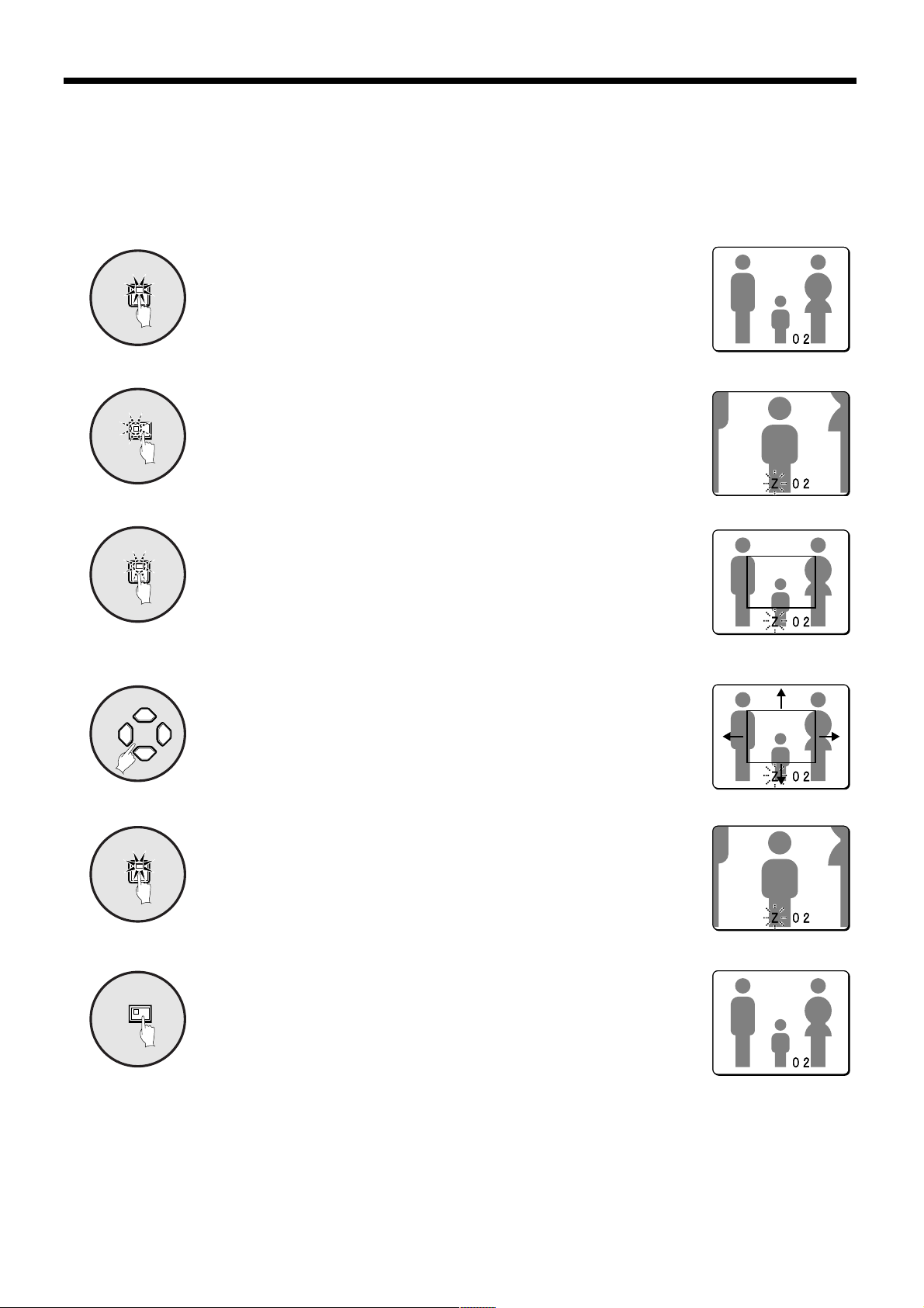
Enlarging images
Press the ZOOM button.
ZOOM
1
The images will be enlarged.
Note: If you set a zoom frame, the area of the image inside the zoom
frame will be enlarged. (See page 17.)
If you press the camera select button while
zooming, the image will be easier to see
Image with little
movement
due to the movement of the subject. The
following changes will occur if you press
the camera select button repeatedly.
2
• An image with little movement (almost a still
image)
Large subjects become clearer and moving
subjects appear a little rough.
• An image with large movement (normal
viewing)
The image of a moving subject becomes clearer
and subjects with little movement appear a little
rough.
To return an enlarged image to normal image display, press
ZOOM
2
the ZOOM button once more.
The zoom will be canceled and normal images will appear.
Enlarged image is a
little rough
Image with large
movement
Enlarged image is a
little rough
Subject becomes
clearer
4
Subject becomes
clearer
– 16 –
English
Page 18
VIEWING CAMERA IMAGES
Example: To zoom in on the camera 2 image and move the zoom frame
You can select the zoom position by means of the zoom frame which appears on the screen. The zoom frame is set initially at
the middle of the screen.
Press camera select button 2.
2
1
ZOOM
2
2
3
The camera 2 image will appear in a single-screen display.
Press the ZOOM button.
The images will be enlarged.
Press and hold camera select button 2 for about 3 seconds or
more.
The zoom will be canceled and the normal image will appear, and the
zoom frame (G) will appear on the screen.
Note: If the zoom frame remains on the screen for about 10 seconds
without being adjusted, the screen will return to zoom display.
To make the zoom frame reappear, press and hold camera select
button 2 again for 3 seconds or more.
Press the cursor buttons to move the zoom frame to the
position you wish to enlarge.
4
Press camera select button 2 once more.
2
5
ZOOM
6
The image in the repositioned zoom frame will be enlarged.
Note: If you press the STILL button while the images are being zoomed,
an enlarged still image will be displayed.
To return an enlarged image to normal image display, press
the ZOOM button once more.
The zoom will be canceled and normal images will appear.
English
– 17 –
Page 19
VIEWING CAMERA IMAGES
Viewing multiple-screen images
Images from the cameras that are connected to the multiplexer can be displayed in several split-screen formats. Furthermore,
the images from each camera can be displayed in any position within the split screen. (See page 41.)
Press the LIVE button.
LIVE
Viewing images as 9-screen or 16-screen displays
Press the MULTI button.
MULTI
The display switches between 9-screen and 16-screen displays each time
the MULTI button is pressed.
To return to a single-screen display, press a camera select button.
For the MPX-CD93P model, only the 9-screen display is available with no
switching.
Viewing images as a 4-screen display
1
QUAD
2
QUAD
Press the QUAD button.
Images appear as a 4-screen display.
Press the QUAD button once more.
Camera images are switched in 4-screen display units (1 – 4, 5 – 8,
9 – 12, 13 – 16) each time the button is pressed.
To return to a single-screen display, press a camera select button.
For the MPX-CD93P model, a 4-screen display of images from cameras
1 – 4, 5 – 8, or 9 – 3 will appear each time the button is pressed.
– 18 –
English
Page 20
VIEWING CAMERA IMAGES
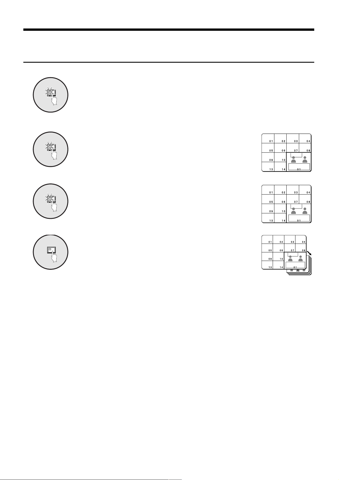
Plus screen viewing
The plus screen allows you to display the image from each
camera as a quarter-screen picture in the lower right corner
of the split-screen display, and images being recorded or
played back can be monitored.
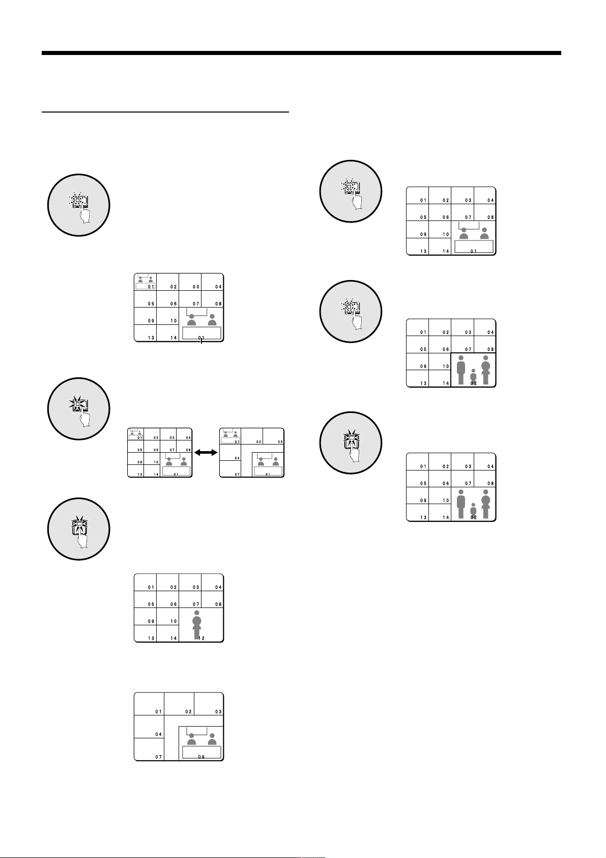
1
PLUS
2
MULTI
Press the PLUS button.
The display changes to show a
13-screen display with a plus screen as
a quarter-screen picture in the
lower-right corner.
For the MPX-CD93P model, a 6-screen
display appears.
Plus screen
Press the MULTI button.
The display switches between
13-screen and 6-screen each time the
MULTI button is pressed.
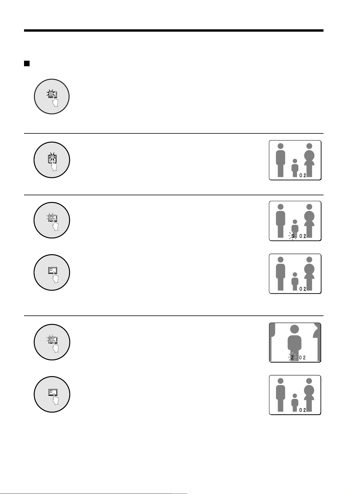
Example: To display images from camera
2 in the plus screen
Set the recording device to playback mode.
1
PLUS
2
VCR
3
2
Press the PLUS button.
The plus screen is displayed.
Press the VCR button.
This sets the plus screen to video
playback mode.
Press camera select button 2.
The plus screen changes to show the
images being recorded by camera 2.
3
12
Press a camera select button
(example: 12).
The images from the selected camera
will be displayed in the plus screen. To
cancel the plus screen, press the
PLUS button once more.
For the MPX-CD93P model, press a
camera select button numbered 9 or
less.
English
– 19 –
Page 21
VIEWING CAMERA IMAGES
Viewing automatically switching images
The camera images are switched automatically in the order that has been set using the SEQUENCE settings. (See page 43.)
Press the LIVE button.
LIVE
Automatically switching of the single-screen images
Switch to single-screen display, and then press the camera
1
1
SEQUENCE
select buttons to select the camera for automatic switching.
The camera select buttons for the cameras that were selected are stored
in memory.
The indicator will illuminate when the next button is pressed.
Press the SEQUENCE button.
2
3
SEQUENCE
To cancel automatic switching, press the SEQUENCE button
once more, or press one of the individual camera select
buttons.
Automatic switching will be canceled and normal images will appear.
– 20 –
English
Page 22
VIEWING CAMERA IMAGES
Automatically switching of the 4-screen images
Press the QUAD button.
QUAD
1
SEQUENCE
2
SEQUENCE
3
Images appear as a 4-screen display.
Press the SEQUENCE button.
Camera images will be switched automatically in 4-screen display units
(1 – 4, 5 – 8, 9 – 12, 13 – 16).
For the MPX-CD93P model, images from cameras 1 – 4, 5 – 8, or 9 – 3
will be switched automatically.
Press the SEQUENCE button once more to return to the
4-screen display.
Automatic switching will be canceled and 4-screen display will be restored.
Automatically switching of the plus screen image
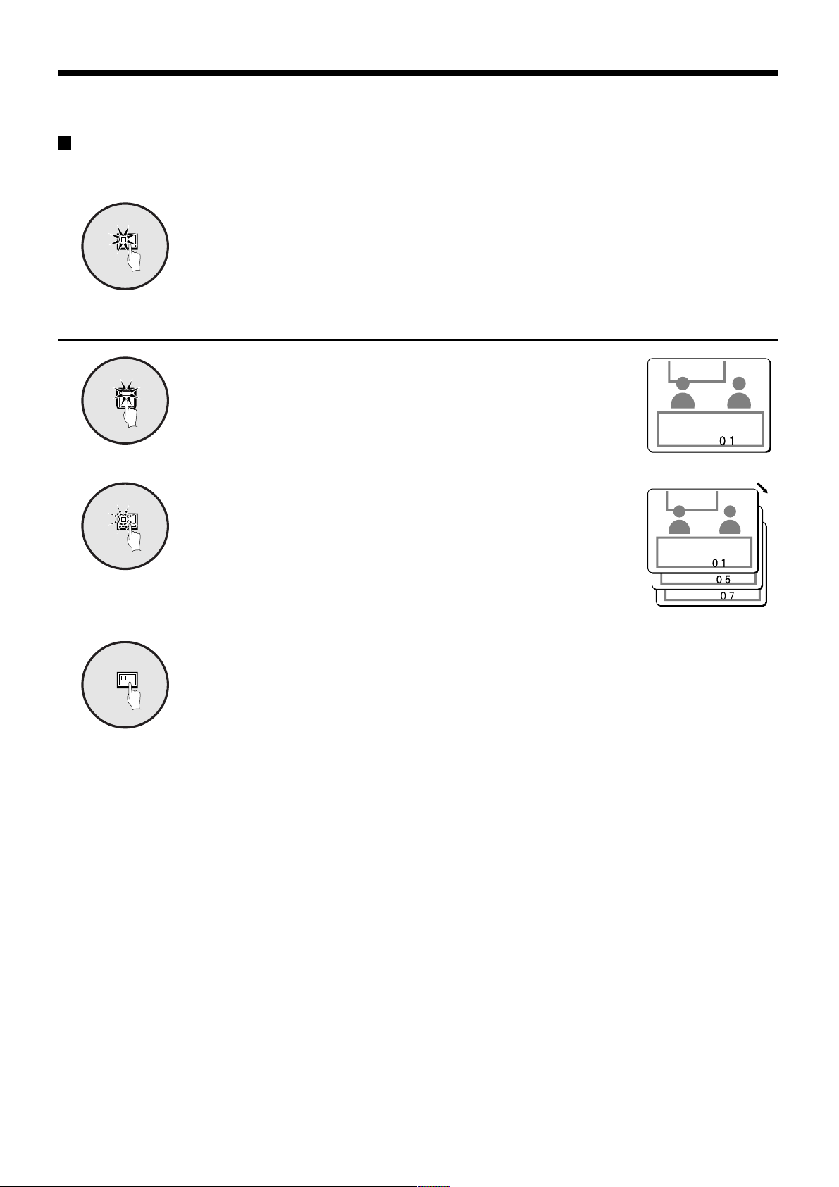
Press the PLUS button.
PLUS
The plus screen is displayed.
1
Press the SEQUENCE button.
SEQUENCE
The camera images in the plus screen will be switched automatically.
2
Press the SEQUENCE button once more to return to the plus
SEQUENCE
3
screen.
Automatic switching will be canceled and the plus screen will appear.
To cancel the plus screen, press the PLUS button once more.
English
– 21 –
Page 23
VIEWING CAMERA IMAGES
Displaying and automatically switching recorded images in the plus screen
Set the recording device to playback mode.
Press the PLUS button.
PLUS
1
VCR
2
SEQUENCE
3
The plus screen is displayed.
Press the VCR button.
This sets the plus screen to video playback mode.
Press the SEQUENCE button.
The playback images in the plus screen will be switched automatically.
4
SEQUENCE
Press the SEQUENCE button once more to return to the plus
screen.
Automatic switching will be canceled and the plus screen will appear.
To cancel the plus screen, press the PLUS button once more.
– 22 –
English
Page 24
VIEWING RECORDED IMAGES
Playing back recorded images in a single-screen display
Press the VCR button to playback from the connected
VCR
Playing back in a single-screen
2
1
Pausing recorded images
STILL
recorder.
Note: Start playback on the recorder. If the playback image was not
recorded through this unit, it will not be displayed correctly. “NO ID”
will appear on the screen.
Press a camera select button (example: 2).
The recorded images will be played back in a single-screen.
Press the STILL button.
The image will be paused.
1
To return a still image to normal image display, press the
STILL
2
Enlarging recorded images
ZOOM
1
ZOOM
2
STILL button once more.
Pausing will be canceled and normal images will appear.
Note: If you press the ZOOM button while an image is paused, the still
Press the ZOOM button.
The images will be enlarged.
Note: If you set a zoom frame, the area of the image inside the zoom
To return an enlarged image to normal image display, press
the ZOOM button once more.
The zoom will be canceled and normal images will appear.
image will be enlarged. To return to the original still image, press
the ZOOM button once more.
frame will be enlarged. (See page 24.)
English
– 23 –
Page 25

VIEWING RECORDED IMAGES
Example: To zoom in on a specific part of the camera 2 image
You can use the zoom frame that appears on the screen to select the position you wish to enlarge. The zoom frame is set
initially at the center of the screen.
Press camera select button 2.
2
1
ZOOM
2
2
3
The camera 2 image will appear in a single-screen display.
Press the ZOOM button.
The images will be enlarged.
Press and hold camera select button 2 for about 3 seconds or
more.
The zoom will be canceled and the normal image will appear, and the
zoom frame (G) will appear on the screen.
Note: If the zoom frame remains on the screen for about 10 seconds
without being adjusted, the screen will return to zoom display.
To make the zoom frame reappear, press and hold camera select
button 2 again for 3 seconds or more.
Press the cursor buttons to determine the position you wish
to enlarge.
4
Press camera select button 2 one more.
2
5
ZOOM
6
The area of the image inside the zoom frame will be enlarged.
Note: If you press the STILL button while the images are being zoomed,
an enlarged still image will be displayed.
Press the ZOOM button once more to return the enlarged
image to the normal image.
The zoom will be canceled and normal images will appear.
– 24 –
English
Page 26

VIEWING RECORDED IMAGES
Playing back multiple-screen displays
Recorded images can be displayed in several split-screen formats. Furthermore, the images from each camera can be displayed
in any position within the split-screen. (See page 41.)
Press the VCR button.
VCR
Playing back images as 9-screen or 16-screen displays
Press the MULTI button.
MULTI
The display switches between 9-screen and 16-screen each time the
MULTI button is pressed.
To return to a single-screen display, press a camera select button.
For the MPX-CD93P model, only the 9-screen display is available with no
switching.
Playing back images as a 4-screen display
1
QUAD
2
QUAD
Press the QUAD button.
Images appear as a 4-screen display.
Press the QUAD button once more.
Camera images are switched in 4-screen display units (1 – 4, 5 – 8,
9 – 12, 13 – 16) each time the button is pressed.
To return to a single-screen display, press a camera select button.
For the MPX-CD93P model, a 4-screen display of images from cameras
1 – 4, 5 – 8, or 9 – 3 will appear each time the button is pressed.
English
– 25 –
Page 27

VIEWING RECORDED IMAGES
Playing back images as 13-screen or 6-screen displays (plus screen)
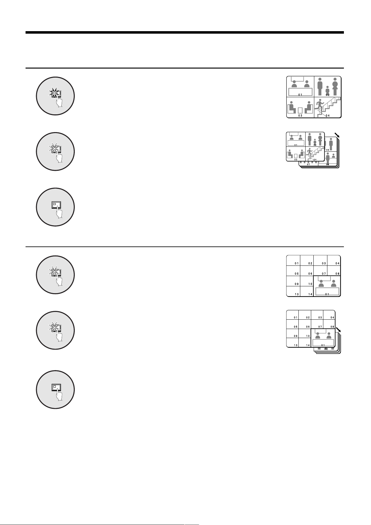
Press the PLUS button.
PLUS
1
MULTI
2
The display changes to show a 13-screen or 6-screen display with a plus
screen as a quarter-screen picture in the lower-right corner.
Press the MULTI button.
The display switches between 13-screen and 6-screen each time the
MULTI button is pressed.
For the MPX-CD93P model, only the 6-screen display is available with no
switching.
Plus screen
Press a camera select button (example: 12).
12
3
The playing back images from the selected camera will be displayed in
the plus screen.
To cancel the plus screen, press the PLUS button once more.
For the MPX-CD93P model, press camera select button 9.
– 26 –
English
Page 28

VIEWING RECORDED IMAGES
Playing back automatically switching images
Recorded images are switched automatically in the order that has been set using the SEQUENCE settings. (See page 43.)
Press the VCR button.
VCR
Automatic switching of the single-screen playback images
Switch to single-screen display, press the camera select
1
1
SEQUENCE
2
buttons to select the camera for automatic switching, and
then repeat this to select the next camera.
Press the SEQUENCE button.
The recorded images are automatically switched in the order set.
3
SEQUENCE
To cancel automatic switching, press the SEQUENCE button
once more, or press one of the individual camera select
buttons.
Automatic switching will be canceled and normal images will appear.
English
– 27 –
Page 29

VIEWING RECORDED IMAGES
Automatically switching of the 4-screen playback images
Press the QUAD button.
QUAD
1
SEQUENCE
2
SEQUENCE
3
Images appear as a 4-screen display.
Press the SEQUENCE button.
Camera images will be switched automatically in 4-screen display units
(1 – 4, 5 – 8, 9 – 12, 13 – 16).
For the MPX-CD93P model, images from cameras 1 – 4, 5 – 8, or 9 – 3
will be switched automatically.
To cancel automatic switching, press the SEQUENCE button
once more.
Automatic switching will be canceled and a 4-screen display will appear.
Automatically switching of the plus screen playback image
Press the PLUS button.
PLUS
The plus screen is displayed.
1
Press the SEQUENCE button.
SEQUENCE
The playback images in the plus screen will be switched automatically.
2
To cancel automatic switching, press the SEQUENCE button
SEQUENCE
3
once more.
Automatic switching will be canceled and a plus screen will appear.
To cancel the plus screen, press the PLUS button once more.
– 28 –
English
Page 30

VIEWING WITH SPOT MONITOR
Four monitors can be connected to the spot monitor output connectors on the rear panel of this unit.
Even while the main monitor is showing camera images as split screens or playback, the camera images can be displayed on
the spot monitors as single-screen or automatic switching images.
Connection and display example
Main monitor
(16-screen display)
Spot monitor 1
(automatic switching)
Spot monitor 2
(single-screen display)
SPOT MONITOR
Spot monitor 3
(automatic switching)
Spot monitor 4
(automatic switching)
Spot Monitor Button Functions
When the SPOT MON. button is pressed in camera image (LIVE) or playback (VCR) mode, each spot monitor goes into
selection standby condition.
If the SPOT MON. button is pressed once more, LIVE or VCR mode is enabled.
• Selection of spot monitor 1
12
• Selection of spot monitor 2
English
1 2
• Selection of spot monitor 3
1 2
• Selection of spot monitor 4
1 2
– 29 –
Page 31

VIEWING WITH SPOT MONITOR
Spot monitor settings
1
SPOT
MON.
2
SPOT
4
MON.
Press the SPOT MON. button.
Camera select buttons 1 to 4 flash and
spot monitor selection standby condition
is enabled.
Note:
If a button from 1 to 4 is pressed
•
while the indicators are flashing, the
spot monitor corresponding to the
number of the button pressed will be
selected.
If MAIN → SPOT1 on the DISPLAY
•
SET menu are ON, the spot monitor
1 image will be the same as the main
monitor screen.
Press a camera select button
(example: 4).
Spot monitor indicator 4 and the SPOT
MON. indicator will flash and S4 will
appear (flashing) on the screen of spot
monitor 4.
Note: S1 to S4 will appear flashing on
the screen of each selected spot
monitor.
3
The image on spot monitor 4 is controlled with
the following buttons.
To view each screen as a single-screen.
•
Press each camera select button.
To set all cameras from 1 to 16 to automatic switching.
•
Press the SEQUENCE button.
To set only cameras 1, 2 and 3 to automatic switching.
•
Specify SPOT MONITOR 4 under SEQUENCE on
DISPLAY SET screen. (See page 45.)
(MAIN MENU)
1 LANGUAGE ¤
2 CLOCK SET ¤
3 DISPLAY SET ¤
4 VCR SET ¤
5 ALARM SET ¤
6 SECURITY SET ¤
7 CONTROL SET ¤
8 ALARM DATA ¤
(*:NEXT)
(SEQUENCE SET)
MAIN MONITOR 1 S ¤
SPOT MONITOR-1 1 S ¤
SPOT MONITOR-2 1 S ¤
SPOT MONITOR-3 1 S ¤
SPOT MONITOR-4 INDIV.¤
QUAD 1 S
INDIV. INTERVAL *
(*:NEXT)
4
Press the SPOT MON. button twice.
Camera image (LIVE) or playback (VCR) mode is enabled.
(DISPLAY SET)
TITLE DOWN ¤
MULTI SCREEN NORMAL¤
SEQUENCE INDIV.¤
MASK ON ¤
MAIN†SPOT1 OFF
DIGITAL CONNECTION OFF
COLOR LEVEL AUTO
(*:NEXT)
(SPOT MON.4 SEQ.SET)
IN IN
01: ON 09: OFF
02: ON 10: OFF
03: ON 11: OFF
04: OFF 12: OFF
05: OFF 13: OFF
06: OFF 14: OFF
07: OFF 15: OFF
08: OFF 16: OFF
Spot monitor 4
– 30 –
English
Page 32

MENU FLOWCHART AND MENU
OPERATIONS
Menu flowchart
(LANGUAGE)
ENGLISH
FRANCAIS
DEUTSCH
ESPANOL
(CLOCK SET)
01-01-2001 MON 00:00:00
TIMER ON ¤
SUMMER TIME ON ¤
NEXT
(*:NEXT)
(TIMER SET)
TIMER-A TIMER-B
T-1 00:00 T-1 00:00
T-2 00:00 T-2 00:00
NEXT
T-3 00:00 T-3 00:00
T-4 00:00 T-4 00:00
SEQUENCE A
PROGRAM REC A
MASK A
MOTION SENSOR A
(SUMMER TIME SET)
WEEK MON TIME
ON LST-SUN 03 02:00
OFF LST-SUN 10 02:00
NEXT
NEXT
(MAIN MENU)
1 LANGUAGE ¤
2 CLOCK SET ¤
3 DISPLAY SET ¤
4 VCR SET ¤
5 ALARM SET ¤
6 SECURITY SET ¤
7 CONTROL SET ¤
8 ALARM DATA ¤
(*:NEXT)
MENU
(DISPLAY SET)
TITLE DOWN ¤
MULTI SCREEN CHANGE¤
SEQUENCE INDIV.¤
MASK ON ¤
MAIN†SPOT1 OFF
NEXT
DIGITAL CONNECTION OFF
COLOR LEVEL AUTO
(*:NEXT)
(VCR SET)
RECORDER TLS
REC.SPEED 3 H
ALARM REC.SPEED 3 H
SW.IN EDGE ó
REC.PICTURE 01
NEXT
PROGRAM REC. ONLY *
(*:NEXT)
(ALARM SET)
ALARM ON *
ACTIVE REC. ON *
MOTION SENSOR ON *
VIDEO LOSS OFF
NEXT
(*:NEXT)
(PROGRAM REC.SET)
T-1
IN IN
01:ON 09:ON
02:ON 10:ON
03:ON 11:ON
04:ON 12:ON
NEXT
05:ON 13:ON
05:ON 14:ON
07:ON 15:ON
08:ON 16:ON
(ALARM OPERATION SET)
ALARM EXT.OR M.SENSOR
DURATION INDIV.*
NEXT
RETRIGGER ON
ALARM LIST ON
BUZZER ON
ALARM DISPLAY ¤
(*:NEXT)
(ACTIVE REC.SET)
AL.REC.EXT.
REC.MODE MODE1
NEXT
NEXT
CAMERA NO.01
(POSITION SET)
QUAD
01 02 : 05 06
03 04 : 07 08
-------------
NEXT
09 10 : 13 14
11 12 : 15 16
(SEQUENCE SET)
MAIN MONITOR 1 S ¤
SPOT MONITOR-1 1 S ¤
SPOT MONITOR-2 1 S ¤
SPOT MONITOR-3 1 S ¤
SPOT MONITOR-4 1 S ¤
NEXT
QUAD 1 S
(*:NEXT)
(MASK SET)
T-1
IN IN
01:OFF 09:OFF
02:OFF 10:OFF
03:OFF 11:OFF
04:OFF 12:OFF
05:OFF 13:OFF
NEXT
06:OFF 14:OFF
07:OFF 15:OFF
08:OFF 16:OFF
--------
01
(ALARM DATA) 1/ 1
CAM DATE TIME ITEM
English
NEXT
(SEQURITY LOCK SET)
OPERATION
CODE 1111
LOCK OFF
SETUP
NEXT
CODE 1111
LOCK OFF
(CONTROL SET)
DATA SPEED 19200
ALARM SEND ON
RS232C/RS485 RS232C
NEXT
CAMERA CONTROL SANYO *
(*:NEXT)
– 31 –
----------------
----------------
----------------
----------------
----------------
----------------
NEXT
----------------
----------------
---------------CAMERA NO.01 T-1 LEVEL:OFF MODE:A ñ
SECURITY CODE ----
(CAMERA CONTROL SET)
IN IN
01:OFF 09:0FF
02:OFF 10:OFF
03:OFF 11:OFF
04:OFF 12:OFF
NEXT
05:OFF 13:OFF
06:OFF 14:OFF
07:OFF 15:OFF
08:OFF 16:OFF
(ALARM DISPLAY SET)
ALARM DISPLAY FULL
DOUBLE ALARM LAST
(SPOT MONITOR SET)
SPOT MONITOR-1 ON
NEXT
SPOT MONITOR-2 ON
SPOT MONITOR-3 ON
SPOT MONITOR-4 ON
Page 33

MENU FLOWCHART AND MENU OPERATIONS
Menu operations
Press the MENU button.
MENU
◆
Status of indicators when a menu screen is displayed
MENU
NEXT
The MAIN MENU screen will be displayed.
Note: The MAIN MENU screen will appear on the main monitor and on
spot monitor 1.
• While the MENU indicator is flashing
When the MENU button is pressed, the menu screen will be
terminated.
• While the NEXT indicator is flashing
When the NEXT button is pressed, a sub-menu screen (the next level)
will appear.
(MAIN MENU)
1 LANGUAGE ¤
2 CLOCK SET ¤
3 DISPLAY SET ¤
4 VCR SET ¤
5 ALARM SET ¤
6 SECURITY SET ¤
7 CONTROL SET ¤
8 ALARM DATA ¤
(*:NEXT)
BACK
• While the BACK indicator is flashing
When the BACK button is pressed, the previous menu screen will be
restored.
MENU
(MAIN MENU)
1 LANGUAGE ¤
2 CLOCK SET ¤
3 DISPLAY SET ¤
4 VCR SET ¤
5 ALARM SET ¤
6 SECURITY SET ¤
7 CONTROL SET ¤
8 ALARM DATA ¤
(*:NEXT)
NEXT NEXT
(CLOCK SET)
01-01-2001 MON 00:00:00
TIMER ON ¤
BACK BACK
MENU
SUMMER TIME OFF
(*:NEXT)
(TIMER SET)
TIMER-A TIMER-B
T-1 00:00 T-1 00:00
T-2 00:00 T-2 00:00
T-3 00:00 T-3 00:00
T-4 00:00 T-4 00:00
SEQUENCE A
PROGRAM REC A
MASK A
MOTION SENSOR A
– 32 –
English
Page 34

LANGUAGE SETTING
Language setting
(MAIN MENU)
1 LANGUAGE ¤
2 CLOCK SET ¤
3 DISPLAY SET ¤
4 VCR SET ¤
5 ALARM SET ¤
6 SECURITY SET ¤
7 CONTROL SET ¤
8 ALARM DATA ¤
(*:NEXT)
(LANGUAGE)
ENGLISH
FRANCAIS
DEUTSCH
ESPANOL
The multiplexer menu screens can be displayed in several languages (English, French, German or Spanish). The default
language setting is English.
LANGUAGE screen display
1
MENU
Press the MENU button.
The MAIN MENU screen will be
displayed.
(MAIN MENU)
1 LANGUAGE ¤
2 CLOCK SET ¤
3 DISPLAY SET ¤
4 VCR SET ¤
5 ALARM SET ¤
6 SECURITY SET ¤
7 CONTROL SET ¤
8 ALARM DATA ¤
(*:NEXT)
2
NEXT
Use the cursor buttons to select
“LANGUAGE” and then press the
NEXT button.
The LANGUAGE screen will be
displayed.
(LANGUAGE)
ENGLISH
FRANCAIS
DEUTSCH
ESPANOL
3
MENU
Use the cursor buttons to select
the language, and then press the
MENU button.
The selected language will be set.
The camera images will be displayed.
(LANGUAGE)
ENGLISH
FRANCAIS
DEUTSCH
ESPANOL
Press the MENU button.
4
English
– 33 –
Page 35

CLOCK SET SETTINGS
(MAIN MENU)
1 LANGUAGE ¤
2 CLOCK SET ¤
3 DISPLAY SET ¤
4 VCR SET ¤
5 ALARM SET ¤
6 SECURITY SET ¤
7 CONTROL SET ¤
8 ALARM DATA ¤
(*:NEXT)
(CLOCK SET)
01-01-2001 MON 00:00:00
TIMER ON ¤
SUMMER TIME ON ¤
(*:NEXT)
Clock setting
Timer setting
Set the timer when using the timer function.
(TIMER SET)
TIMER-A TIMER-B
T-1 00:00 T-1 00:00
T-2 00:00 T-2 00:00
T-3 00:00 T-3 00:00
T-4 00:00 T-4 00:00
SEQUENCE A
PROGRAM REC A
MASK A
MOTION SENSOR A
Summer time setting
(SUMMER TIME SET)
WEEK MON TIME
ON LST-SUN 03 02:00
OFF LST-SUN 10 02:00
The CLOCK SET menu is used to set the time. It is also used to set a timer when using the timer function, and to make summer
time settings.
– 34 –
English
Page 36

15-10-2002 15:20:00
CLOCK SET-1
CLOCK SET SETTINGS
Clock settings (default setting: 01-01-2001 MON 00:00:00)
Be sure to set the clock to the correct time.
The correct time must be set in order for the timer setting and summer time setting functions to work correctly.
Example: Setting the clock to October 15, 2002 at 3:20 PM
1
MENU
The MAIN MENU screen will be
displayed.
(MAIN MENU)
1 LANGUAGE ¤
2 CLOCK SET ¤
3 DISPLAY SET ¤
4 VCR SET ¤
5 ALARM SET ¤
6 SECURITY SET ¤
7 CONTROL SET ¤
8 ALARM DATA ¤
(*:NEXT)
Press the MENU button.
• Press the setting buttons to set
the year (2002), then press the
cursor button.
• Press the setting buttons to set
the hours (15), then press the
cursor button.
• Press the setting buttons to set
the minutes (20), then press the
cursor button.
(CLOCK SET)
15-10-2002 TUE 00:00:00
(CLOCK SET)
15-10-2002 TUE 15:00:00
(CLOCK SET)
15-10-2002 TUE 15:20:00
The time setting is finished.
2
NEXT
Use the cursor buttons to select
“CLOCK SET”, and then press
the NEXT button.
Note: The day of the week will be automatically set
according to the date entered.
The CLOCK SET screen will be
displayed.
(CLOCK SET)
01-01-2001 MON 00:00:00
TIMER ON *
SUMMER TIME OFF
BACK
Use the cursor buttons to select
3
“01”, and then use the setting
+–
buttons to set the date.
☞To display date, time and camera number
While the camera image is displayed, press the
BACK button repeatedly. The following actions
will occur:
Date and time
15-10-2002 15 : 20 : 00
Camera number
01
Date, time and camera number
15-10-2002 15 : 20 : 00
Cancel display
01
(CLOCK SET)
01-01-2001 MON 00:00:00
TIMER ON *
SUMMER TIME OFF
15-10-2002 15:20:00
01
Date and time is displayed.
Note: This setting can be change separately for
4
+–
• Press the setting buttons to set the
day (15), then press the cursor
buttons.
(CLOCK SET)
15-01-2001 MON 00:00:00
camera images and playback images.
☞Setting the time (minutes and seconds) to
00 during monitoring
Press the MENU RESET button. The minutes
and seconds will then be reset to 00.
• Press the setting buttons to set
the month (10), then press the
cursor button.
(CLOCK SET)
15-10-2001 MON 00:00:00
Note: These operations must only be carried out
while camera images are being displayed.
If you press these buttons while a menu
screen is being displayed, the setting values
will be reset to their defaults.
CLOCK SET-1
English
– 35 –
Page 37

CLOCK SET SETTINGS
CLOCK SET-2
TIMER settings
(default setting: 00:00)
The timer function uses two separate timer settings (TIMER-A
and TIMER-B), and each timer setting can be made in four
time zones (example: midnight, morning, daytime, evening).
For example, TIMER-A time zones can be set for automatic
screen switching and TIMER-B time zones can be set for
gray pattern cover on camera images.
☞ Operable functions during the
period set by the timer
Each of the following menu settings is required to operate
these timer functions. After you have made the menu
settings, be sure to make the timer settings.
• To change camera images
into automatic switching
screens.
Set “SEQUENCE” on
DISPLAY SET screen
• To cover camera images
with gray pattern.
Set “MASK” on DISPLAY SET
screen
• To record camera images on
a video unit
Set “PROGRAM REC.” on
VCR SET screen
(DISPLAY SET)
TITLE DOWN ¤
MULTI SCREEN NORMAL
SEQUENCE INDIV.*
MASK ON *
MAIN†SPOT1 OFF
DIGITAL CONNECTION OFF
COLOR LEVEL AUTO
(*:NEXT)
(VCR SET)
RECORDER TLS
REC.SPEED 3 H
ALARM REC.SPEED 3 H
SW.IN EDGE ñ
REC.PICTURE 01
PROGRAM REC. ONLY *
(*:NEXT)
For these settings, set Example 2 consecutively with
Example 1.
Example 1: Set TIMER-A and TIMER-B
time zones as follows
(TIMER-A settings) (TIMER-B settings)
T-1 6 a.m. (6:00) T-1 8 a.m. (8:00)
T-2 12:30 p.m. (12:30) T-2 2:30 p.m. (14:30)
T-3 6 p.m. (18:00) T-3 8 p.m. (20:00)
T-4 4 a.m. (4:00) T-4 6 a.m. (6:00)
Press the MENU button, use the
1
MENU
2
3
NEXT
+–
cursor button to select CLOCK
SET and then press the NEXT
button.
Use the cursor buttons to select
TIMER “OFF”.
(CLOCK SET)
15-10-2001 MON 15:20:00
TIMER OFF
SUMMER TIME OFF
Press the setting buttons to
select “ON”, and then press the
NEXT button.
The TIMER SET screen will be
displayed.
(CLOCK SET)
15-10-2001 MON 15:20:00
TIMER ON *
SUMMER TIME OFF
• To detect an alarm input in a
camera image
Set “MOTION SENSOR” on
ALARM SET screen
(ALARM SET)
ALARM OFF
ACTIVE REC. OFF
MOTION SENSOR ON *
VIDEO LOSS OFF
(*:NEXT)
– 36 –
Use the cursor buttons to select
4
+–
TIMER-A “T-1 00:” (hours), and
then use the setting buttons to
set the hours to “06”.
(TIMER SET)
TIMER-A TIMER-B
T-1 06:00 T-1 00:00
T-2 00:00 T-2 00:00
T-3 00:00 T-3 00:00
T-4 00:00 T-4 00:00
CLOCK SET-2
English
Page 38

CLOCK SET-3
CLOCK SET SETTINGS
5
Use the cursor buttons to select
TIMER-A “T-1 :00” (minutes), and
+–
then use the setting buttons to
set the minutes to “00”.
(TIMER SET)
TIMER-A TIMER-B
T-1 06:00 T-1 00:00
T-2 00:00 T-2 00:00
T-3 00:00 T-3 00:00
T-4 00:00 T-4 00:00
Example 2: Set the timer operation as
follows
☞To set TIMER-A time zones to automatic switching
screen and monitor mask.
☞To set TIMER-B timer zones to program recording and
motion sensor.
Use the cursor buttons to select
1
6
Use the cursor buttons to select
+–
TIMER-A “T-2 00:” (hours), and
+–
then use the setting buttons to
set the hours to “12”.
(TIMER SET)
TIMER-A TIMER-B
T-1 06:00 T-1 00:00
T-2 12:00 T-2 00:00
T-3 00:00 T-3 00:00
T-4 00:00 T-4 00:00
2
+–
SEQUENCE “A”, and then use
the setting buttons to set “A”.
(TIMER-A setting)
SEQUENCE A
PROGRAM REC A
MASK A
MOTION SENSOR A
Use the cursor buttons to select
PROGRAM REC “A”, and then
use the setting buttons to set
Use the cursor buttons to select
7
+–
TIMER-A “T-2 00” (minutes), and
then use the setting buttons to
set the minutes to “30”.
(TIMER SET)
TIMER-A TIMER-B
T-1 06:00 T-1 00:00
T-2 12:30 T-2 00:00
T-3 00:00 T-3 00:00
T-4 00:00 T-4 00:00
3
+–
“B”. (TIMER-B setting)
SEQUENCE A
PROGRAM REC B
MASK A
MOTION SENSOR A
Use the cursor buttons to select
MASK “A”, and then use the
setting buttons to set “A”.
Repeat steps 4 and 5 to set the
hours and minutes for T-3 and
T-4 also.
SEQUENCE A
PROGRAM REC B
MASK A
MOTION SENSOR A
8
Note:
Initial settings T-1 to T-4 are “00:00”
•
In this case, the timer will operate at all times set by T-1.
The time divisions of the timer settings (T-1 to T-4) are
•
continuous settings in one cycle from start time to end time.
For instance, in the case of T-1 (6:00) and T-2 (12:30), the
domain of timer T-1 is from 6 a.m. until 12:30 p.m.
If two more timers are set to the same starting time, the
•
timers will operate together for the same period of time.
When setting the timers, a setting cannot be entered if, for
•
instance, T-3 as been set to earlier than T-1. If this
happens, re-enter the correct settings.
to set the hours and minutes for
+–
T-1, T-2, T-3 and T-4.
(TIMER SET)
TIMER-A TIMER-B
T-1 06:00 T-1 08:00
T-2 12:30 T-2 14:30
T-3 18:00 T-3 20:00
T-4 04:00 T-4 06:00
Use the same procedure TIMER-B
4
+–
Use the cursor buttons to select
MOTION SENSOR “A”, and then
use the setting buttons to set “B”.
SEQUENCE A
PROGRAM REC B
MASK A
MOTION SENSOR A
5
BACK
Press the BACK button.
The setting will then be completed and
the display will return to the CLOCK
SET screen.
Press the BACK button once more to
return to the MAIN MENU screen.
CLOCK SET-3
English
– 37 –
Page 39

CLOCK SET SETTINGS
CLOCK SET-4
SUMMER TIME setting
(default setting: OFF)
You can set the starting time and ending time for summer
time.
When summer time is set, the time is automatically advanced
by one hour during the summer period.
☞
To make changes to the settings
Example: Setting the summer time from
the second Tuesday of May at
3:00 AM, to the fourth Tuesday
of September at 3:00 AM.
1
MENU
2
Press the MENU button, use the
cursor button to select CLOCK
SET and then press the NEXT
button.
Use the cursor buttons to select
SUMMER TIME “OFF”.
(CLOCK SET)
15-10-2001 MON 15:30:00
TIMER OFF
SUMMER TIME OFF
4
+–
(SUMMER TIME SET)
WEEK MON TIME
ON 2ND-SUN 03 02:00
OFF LST-SUN 10 02:00
the WEEK (2ND), then press the
cursor button.
Menu: 1ST, 2ND, 3RD, 4TH or LST
(first, second, third, fourth or
last)
• Press the setting buttons to set the WEEK
• Press the setting buttons to set
(TUE), then press the cursor button.
Menu: SUN, MON, TUE, WED, THU, FRI or SAT
(SUMMER TIME SET)
WEEK MON TIME
ON 2ND-TUE 03 02:00
OFF LST-SUN 10 02:00
• Press the setting buttons to set the MON (05),
then press the cursor button.
Menu: 1, 2, 3, 4 ..... 11, 12
(for January, February, March .....
December)
(SUMMER TIME SET)
WEEK MON TIME
ON 2ND-TUE 05 02:00
OFF LST-SUN 10 02:00
• Press the setting buttons to set the TIME (03),
then press the cursor button.
(SUMMER TIME SET)
WEEK MON TIME
ON 2ND-TUE 05 03:00
OFF LST-SUN 10 02:00
3
NEXT
+–
Press the setting buttons to
change the setting to ON, and
then press the NEXT button.
5
+–
The SUMMER TIME SET screen will be
displayed.
(CLOCK SET)
15-10-2001 MON 15:30:00
TIMER OFF
SUMMER TIME ON *
(*:NEXT)
6
Press the MENU button.
Following the same procedure as
above, set when the time is changed
back from summer time to standard
time (the OFF settings).
(SUMMER TIME SET)
WEEK MON TIME
ON 2ND-TUE 05 03:00
OFF 4TH-TUE 09 03:00
The display will return to the normal screen.
CLOCK SET-4
– 38 –
English
Page 40

DISPLAY SET SETTINGS
(MAIN MENU)
1 LANGUAGE ¤
2 CLOCK SET ¤
3 DISPLAY SET ¤
4 VCR SET ¤
5 ALARM SET ¤
6 SECURITY SET ¤
7 CONTROL SET ¤
8 ALARM DATA ¤
(*:NEXT)
(DISPLAY SET)
TITLE DOWN ¤
MULTI SCREEN CHANGE¤
SEQUENCE INDIV.¤
MASK ON ¤
MAIN†SPOT1 OFF
DIGITAL CONNECTION OFF
COLOR LEVEL AUTO
(*:NEXT)
Use the timer function to set
automatic switching display.
(See page 45.)
When the timer function is set, the
camera images can be
automatically switched during the
set time zone.
Title setting and display position setting (See page 40.)
CAMERA NO.
--
-------
Enter a title.
001
CAMERA NO.01 CAM
CAMERA NO.01 CAM
DESK
DESK
Camera image sorting (See page 41.)
(POSITION SET)
MULTI16
01 02 03 04
05 06 07 08
09 10 11 12
13 14 15 16
Automatic switching time setting (See page 43.)
All camera images switch in
intervals of the set period of time.
If set to 5 seconds, the
images switch automatically
in intervals of 5 seconds.
Select the camera to be automatically switched. The
images will switch in intervals of the set period of time.
(MAIN MON.SEQ SET)
T-4
IN IN
01:ON 09:ON
02:ON 10:ON
03:ON 11:ON
04:ON 12:ON
05:ON 13:ON
06:ON 14:ON
07:ON 15:ON
08:ON 16:ON
Select the cameras. The selected camera images
switch automatically.
001
001
Set the title
display
position.
To mask the monitor by using
timer functions (See page 47.)
When timer functions are set,
camera images can be covered
with a gray pattern at the set time
zones.
Timer setting (See page 36.)
(CLOCK SET)
01-01-2002 TUE 00:00:00
TIMER ON ¤
SUMMER TIME ON *
(*:NEXT)
(TIMER SET)
TIMER-A TIMER-B
T-1 00:00 T-1 00:00
T-2 00:00 T-2 00:00
T-3 00:00 T-3 00:00
T-4 00:00 T-4 00:00
SEQUENCE A
PROGRAM REC A
MASK A
MOTION SENSOR A
(PROGRAM REC.SET)
(PROGRAM REC SET)
T-1
(PROGRAM REC SET)
TIMER-1
IN IN
(PROGRAM REC SET)
TIMER-1
IN IN
01:ON 09:ON
TIMER-1
IN IN
01:ON 09:ON
02:ON 10:ON
IN IN
01:ON 09:ON
02:ON 10:ON
03:ON 11:ON
01:ON 09:ON
02:ON 10:ON
03:ON 11:ON
04:ON 12:ON
02:ON 10:ON
03:ON 11:ON
04:ON 12:ON
05:ON 13:ON
03:ON 11:ON
04:ON 12:ON
05:ON 13:ON
05:ON 14:ON
04:ON 12:ON
05:ON 13:ON
05:ON 14:ON
07:ON 15:ON
05:ON 13:ON
05:ON 14:ON
07:ON 15:ON
08:ON 16:ON
05:ON 14:ON
07:ON 15:ON
08:ON 16:ON
07:ON 15:ON
08:ON 16:ON
08:ON 16:ON
Monitor mask setting (See page 47.)
(MASK SET)
T-1
IN IN
01:OFF 09:OFF
02:OFF 10:ON
03:OFF 11:OFF
04:OFF 12:OFF
05:ON 13:OFF
06:OFF 14:OFF
07:OFF 15:ON
08:OFF 16:OFF
Select the
camera that is not
to be displayed.
Images from the
selected camera
are not
displayed.
MAIN → SPOT1 setting (See page 49.)
Main monitor images are displayed on spot monitor 1.
Image output at the
main monitor connector
Image output at the
spot monitor 1 connector
DIGITAL CONNECTION settings (See page 50.)
Specify a main unit and sub-units when several of these unit are connected.
Specify as
main unit
If connected to a digital video recorder, make the DVR settings.
Connect to the digital video recorder.
Specify as
sub-unit 1
Specify as
sub-unit 2
Specify as
sub-unit 3
English
COLOR LEVEL settings (See page 51.)
Adjust the monitor screen color level.
– 39 –
Page 41

DISPLAY SET-1
DISPLAY SET SETTINGS
TITLE setting (default setting: DOWN)
A title such as the setup location can be set for each camera, and the position for displaying this title on the monitor screen can
also be changed.
Example: To assign a title of “HALL-1F” to camera 3 and set the display position to the
top of the monitor
1
MENU
2
NEXT
The MAIN MENU screen will be
displayed.
(MAIN MENU)
1 LANGUAGE ¤
2 CLOCK SET ¤
3 DISPLAY SET ¤
4 VCR SET ¤
5 ALARM SET ¤
6 SECURITY SET ¤
7 CONTROL SET ¤
8 ALARM DATA ¤
(*:NEXT)
Use the cursor buttons to select
“DISPLAY SET” and then press
the NEXT button.
The DISPLAY SET screen will be
Press the MENU button.
5
3
6
+–
displayed.
(DISPLAY SET)
TITLE DOWN ¤
MULTI SCREEN NORMAL
SEQUENCE 1 S
MASK OFF
MAIN†SPOT1 OFF
DIGITAL CONNECTION OFF
COLOR LEVEL AUTO
(*:NEXT)
If the title is to be altered, use the cursor buttons to
bring the cursor to the item that is to be changed
Press camera select button 3.
The images from camera 3 will be
displayed on the monitor, and the cursor
will appear at the default title setting
position.
CAMERA NO.03 --------03
Use the setting buttons to
display “H”, and then press the
cursor button.
If the cursor button is pressed to the
right, the cursor will move to the right.
Use this procedure to enter “HALL-1F”.
and select a setting button.
3
TITLE “DOWN”.
(DISPLAY SET)
TITLE DOWN ¤
MULTI SCREEN NORMAL
SEQUENCE 1 S
Use the cursor buttons to select
Note: Characters that can be displayed in a title
Alphabetic characters (A – Z)
•
Numerals (0 – 9)
•
Symbols (–, :, ., /, *, _<blank space>)
•
CAMERA NO.03 H-------03 CAMERA NO.03 HALL-1F-03
4
NEXT
+–
“UP”, and then press the NEXT
button.
The normal monitoring screen will be
displayed and the title will appear at the
top of the screen.
(DISPLAY SET)
TITLE UP ¤
MULTI SCREEN NORMAL
SEQUENCE 1 S
CAMERA NO.01 --------01
– 40 –
Note: To change the title display position, press the
BACK button and then re-select “UP” or
“DOWN” for the TITLE setting.
7
BACK
Press the BACK button.
The setting will then be completed and
the display will return to the DISPLAY
SET screen.
Press the BACK button once more to
return to the MAIN MENU screen.
DISPLAY SET-1
English
Use the setting buttons to select
Page 42

DISPLAY SET-2
DISPLAY SET SETTINGS
MULTI SCREEN setting (default setting: NORMAL)
The order in which camera images are displayed in 4-screen, 9-screen and 16-screen displays can be set as desired.
Note: The same camera image cannot be displayed more than once on the same screen.
Example 1: To display camera 1 image on cameras 06, 11, 16 (in a 4-screen display)
The MPX-CD93P model can display only cameras 01 to 09.
1
MENU
The MAIN MENU screen will be
Press the MENU button.
5
displayed.
(MAIN MENU)
1 LANGUAGE ¤
2 CLOCK SET ¤
3 DISPLAY SET ¤
4 VCR SET ¤
5 ALARM SET ¤
6 SECURITY SET ¤
7 CONTROL SET ¤
8 ALARM DATA ¤
(*:NEXT)
2
NEXT
Use the cursor buttons to select
“DISPLAY SET” and then press
Use the cursor buttons to move
the cursor to “06”, and then
+–
press the setting buttons to
change the setting to “01”.
06 will change to 01.
(POSITION SET)
QUAD
01 02 : 05 06
03 04 : 07 08
------------ 09 10 : 13 14
11 12 : 15 16
(POSITION SET)
QUAD
01 02 : 05 01
03 04 : 07 08
------------ 09 10 : 13 14
11 12 : 15 16
the NEXT button.
The DISPLAY SET screen will be
displayed.
(DISPLAY SET)
TITLE DOWN ¤
MULTI SCREEN NORMAL
SEQUENCE 1 S
MASK OFF
MAIN†SPOT1 OFF
DIGITAL CONNECTION OFF
COLOR LEVEL AUTO
(*:NEXT)
3
Use the cursor buttons to select
MULTI SCREEN “NORMAL”.
(DISPLAY SET)
TITLE DOWN ¤
MULTI SCREEN NORMAL
SEQUENCE 1 S
MASK OFF
MAIN†SPOT1 OFF
DIGITAL CONNECTION OFF
COLOR LEVEL AUTO
(*:NEXT)
6
Display example:
Repeat step 5 to set the images
in 01 to 11 and 16 also.
+–
You can check the setting by pressing
the NEXT button.
Press the NEXT button once more to
return to the setting screen.
(POSITION SET)
QUAD
01 02 : 05 01
03 04 : 07 08
------------ 09 10 : 13 14
01 12 : 15 01
4
English
Use the setting buttons to select
NEXT
+–
“CHANGE”, and then press the
1 – 45 – 8
NEXT button.
A 4-screen camera layout screen will be
displayed.
(DISPLAY SET)
TITLE DOWN ¤
MULTI SCREEN CHANGE*
SEQUENCE 1 S
MASK OFF
(POSITION SET)
QUAD
01 02 : 05 06
03 04 : 07 08
------------ 09 10 : 13 14
11 12 : 15 16
7
BACK
9 – 12 13 – 16
Press the BACK button.
The setting will then be completed and
the display will return to the DISPLAY
SET screen.
Press the BACK button once more to
return to the MAIN MENU screen.
DISPLAY SET-2
– 41 –
Page 43

4
DISPLAY SET-3
DISPLAY SET SETTINGS
Example 2: To display the image from camera 16 at camera 05 position (in a 16-screen
display)
1
NEXT
+–
Use the setting buttons to select “CHANGE”, and then press the
NEXT button.
A 4-screen camera layout screen will be displayed.
2
+–
Press the setting buttons until the 16-screen setting screen is
displayed.
(DISPLAY SET)
TITLE DOWN ¤
MULTI SCREEN CHANGE*
SEQUENCE 1 S
MASK OFF
MAIN†SPOT1 OFF
DIGITAL CONNECTION OFF
COLOR LEVEL AUTO
(*:NEXT)
The display changes to a 9-screen, 16-screen and 4-screen display in that order.
(POSITION SET)
(POSITION SET)
MULTI9
01 02 03
04 05 06
07 08 09
MULTI16
01 02 03 04
05 06 07 08
09 10 11 12
13 14 15 16
(POSITION SET)
QUAD
01 02 : 05 06
03 04 : 07 08
------+----- 09 10 : 13 14
11 12 : 15 16
The “MULTI16” screen is not available on the MPX-CD93P model.
3
Use the cursor buttons to move the
+–
cursor to “05”, and then press the setting
buttons to change the setting to “16”.
05 will change to 16 and 16 will change to 05.
(POSITION SET)
MULTI16
01 02 03 04
05 06 07 08
09 10 11 12
13 14 15 16
(POSITION SET)
MULTI16
01 02 03 04
16 06 07 08
09 10 11 12
13 14 15 05
BACK
You can check the setting by pressing the NEXT
button.
Press the NEXT button once more to return to
the setting screen.
Press the BACK button.
The setting will then be completed and the display will return to the DISPLAY
SET screen.
Press the BACK button once more to return to the MAIN MENU screen.
DISPLAY SET-3
– 42 –
English
Page 44

DISPLAY SET-4
DISPLAY SET SETTINGS
SEQUENCE setting (default setting: 1S)
This lets you set the automatic switching time. The switching time setting for automatic switching display is only effective for
single-screen and 4-screen displays. Two types of setting can be made: all cameras can be switched at the same time, or the
switching times can be set separately for each camera.
Example 1: To set 5-second intervals for automatic switching display of all main and
spot monitor images
1
MENU
The MAIN MENU screen will be
Press the MENU button.
5
BACK
displayed.
(MAIN MENU)
1 LANGUAGE ¤
2 CLOCK SET ¤
3 DISPLAY SET ¤
4 VCR SET ¤
5 ALARM SET ¤
6 SECURITY SET ¤
7 CONTROL SET ¤
8 ALARM DATA ¤
(*:NEXT)
6
SEQUENCE
2
NEXT
Use the cursor buttons to select
“DISPLAY SET” and then press
the NEXT button.
The DISPLAY SET screen will be
displayed.
(DISPLAY SET)
TITLE DOWN ¤
MULTI SCREEN NORMAL
SEQUENCE 1 S
MASK OFF
MAIN†SPOT1 OFF
DIGITAL CONNECTION OFF
COLOR LEVEL AUTO
(*:NEXT)
Press the BACK button.
The setting will then be completed and
the display will return to the MAIN
MENU screen.
When the MENU button is pressed, the
display returns to camera image display
screen.
Press the SEQUENCE button while
the camera image display screen is
displayed.
The screen will switch to 5-second
intervals.
To stop the screen from switching,
press the SEQUENCE button once
more.
DISPLAY SET-4
Use the cursor buttons to select
3
SEQUENCE “1S”.
(DISPLAY SET)
TITLE DOWN ¤
MULTI SCREEN NORMAL
SEQUENCE 1 S
MASK OFF
MAIN†SPOT1 OFF
DIGITAL CONNECTION OFF
COLOR LEVEL AUTO
(*:NEXT)
4
+–
Use the setting buttons to select
“5S”.
Images can then be switched at
intervals of 5 seconds.
(DISPLAY SET)
TITLE DOWN ¤
MULTI SCREEN NORMAL
SEQUENCE 5 S
MASK OFF
MAIN†SPOT1 OFF
DIGITAL CONNECTION OFF
COLOR LEVEL AUTO
(*:NEXT)
English
– 43 –
Page 45

DISPLAY SET-5
DISPLAY SET SETTINGS
Example 2: To set the automatic switching period for the main monitor.
Set cameras 1 to 8 to 2-second automatic switching displays.
•
Set cameras 9 to 16 to 3-second automatic switching displays.
•
Note: The automatic switching display period for spot monitors can be set in the same way (when the setting conditions for each
camera are the same as for the main monitor).
Use the cursor buttons to select
1
SEQUENCE “1S”.
(DISPLAY SET)
TITLE DOWN ¤
MULTI SCREEN NORMAL
SEQUENCE 1 S
MASK OFF
MAIN†SPOT1 OFF
DIGITAL CONNECTION OFF
COLOR LEVEL AUTO
(*:NEXT)
5
Use the setting button (–) to
2
NEXT
–
select “INDIV.”, and then press
the NEXT button.
The SEQUENCE SET screen will be
displayed.
(DISPLAY SET)
TITLE DOWN ¤
MULTI SCREEN NORMAL
SEQUENCE INDIV.*
MASK OFF
MAIN†SPOT1 OFF
DIGITAL CONNECTION OFF
COLOR LEVEL AUTO
(*:NEXT)
3
–
Use the cursor buttons to select
the MAIN MONITOR “1S” setting,
6
MENUBACK
and then press the setting button
Use the cursor buttons to select
“01:1S”, and then press the
+–
setting buttons to change the
setting to “2S”.
Automatic switching display at the
specified switching interval is enabled
when you have entered a switching
period for each camera.
With the same procedure:
Set 02 to 08 to 2 S.
•
Move the cursor to the right and set
•
09 to 16 to 3 S.
(INDIVIDUAL INTERVAL)
IN IN
01: 1 S 09: 1 S
02: 1 S 10: 1 S
03: 1 S 11: 1 S
04: 1 S 12: 1 S
05: 1 S 13: 1 S
06: 1 S 14: 1 S
07: 1 S 15: 1 S
08: 1 S 16: 1 S
Press the BACK button.
The setting will then be completed.
Press the BACK button once more to
return to the MAIN MENU screen.
(INDIVIDUAL INTERVAL)
IN IN
01: 2 S 09: 3 S
02: 2 S 10: 3 S
03: 2 S 11: 3 S
04: 2 S 12: 3 S
05: 2 S 13: 3 S
06: 2 S 14: 3 S
07: 2 S 15: 3 S
08: 2 S 16: 3 S
(–) to change the setting to
“INDIV.”.
INDIV. INTERVAL appears at the
bottom of the screen.
(SEQUENCE SET)
MAIN MONITOR INDIV.¤
SPOT MONITOR-1 1 S ¤
SPOT MONITOR-2 1 S ¤
SPOT MONITOR-3 1 S ¤
SPOT MONITOR-4 1 S ¤
QUAD 1 S
INDIV. INTERVAL *
(*:NEXT)
Press the MENU button.
The display will return to the camera
image display screen.
If the SEQUENCE button is then
pressed, the screen images will start
switching automatically according to the
settings that have been made.
DISPLAY SET-5
4
NEXT
Use the cursor buttons to select
“INDIV. INTERVAL” and then
press the NEXT button.
The INDIVIDUAL INTERVAL screen will
be displayed.
(SEQUENCE SET)
MAIN MONITOR INDIV.¤
SPOT MONITOR-1 1 S ¤
SPOT MONITOR-2 1 S ¤
SPOT MONITOR-3 1 S ¤
SPOT MONITOR-4 1 S ¤
QUAD 1 S
INDIV. INTERVAL *
(*:NEXT)
– 44 –
English
Page 46

DISPLAY SET-6
DISPLAY SET SETTINGS
Example 3: To set a 5-second interval for the automatic switching display of main
monitor images and to use the timer function to set a period when automatic
switching display is not required.
1
Set “TIMER” on CLOCK SET to ON, set each
timer of TIMER-A and TIMER-B on TIMER SET
to SEQUENCE and terminate CLOCK SET.
Press the MENU button.
2
MENU
3
NEXT
The MAIN MENU screen will be
displayed.
(MAIN MENU)
1 LANGUAGE ¤
2 CLOCK SET ¤
3 DISPLAY SET ¤
4 VCR SET ¤
5 ALARM SET ¤
6 SECURITY SET ¤
7 CONTROL SET ¤
8 ALARM DATA ¤
(*:NEXT)
Use the cursor buttons to select
“DISPLAY SET” and then press
the NEXT button.
The DISPLAY SET screen will be
displayed.
(DISPLAY SET)
TITLE DOWN ¤
MULTI SCREEN NORMAL
SEQUENCE 1 S
MASK OFF
MAIN†SPOT1 OFF
DIGITAL CONNECTION OFF
COLOR LEVEL AUTO
(*:NEXT)
4
Use the cursor buttons to select
SEQUENCE “1S”.
(DISPLAY SET)
TITLE DOWN ¤
MULTI SCREEN NORMAL
SEQUENCE 1 S
MASK OFF
MAIN†SPOT1 OFF
DIGITAL CONNECTION OFF
COLOR LEVEL AUTO
(*:NEXT)
6
7
8
+–
NEXT
+–
Use the cursor buttons to select
the MAIN MONITOR “1S” setting,
and then press the setting
buttons to change the setting to
“5S”.
The automatic switching period for the
main monitor will be set to 5 seconds.
(SEQUENCE SET)
MAIN MONITOR 5 S ¤
SPOT MONITOR-1 1 S ¤
SPOT MONITOR-2 1 S ¤
SPOT MONITOR-3 1 S ¤
SPOT MONITOR-4 1 S ¤
QUAD 1 S
(*:NEXT)
Press the NEXT button.
The MAIN MON. SEQ SET “T-1”
screen will be displayed.
This screen is for selecting whether
images from cameras 1 to 16 will be
displayed at the time specified by the
timer (T-1).
Note: T-1 will not be displayed if TIMER
on CLOCK SET is OFF.
(MAIN MON.SEQ SET)
T-1
IN IN
01:ON 09:ON
02:ON 10:ON
03:ON 11:ON
04:ON 12:ON
05:ON 13:ON
06:ON 14:ON
07:ON 15:ON
08:ON 16:ON
Use the cursor buttons to select
“example: 01:ON”, and then
press the setting buttons to
change the setting to “OFF”.
Use the same procedure to set OFF
cameras 2 (02) to 08.
5
–
English
NEXT
Use the setting button (–) to
select “INDIV.” and then press
the NEXT button.
The SEQUENCE SET screen will be
displayed.
(DISPLAY SET)
TITLE DOWN ¤
MULTI SCREEN NORMAL
SEQUENCE INDIV.*
MASK OFF
MAIN†SPOT1 OFF
DIGITAL CONNECTION OFF
COLOR LEVEL AUTO
(*:NEXT)
– 45 –
(MAIN MON.SEQ SET)
T-1
IN IN
01:OFF 09:ON
02:OFF 10:ON
03:OFF 11:ON
04:OFF 12:ON
05:OFF 13:ON
06:OFF 14:ON
07:OFF 15:ON
08:OFF 16:ON
DISPLAY SET-6
Page 47

DISPLAY SET SETTINGS
DISPLAY SET-7
9
10
Use the cursor buttons to select
“T-1”, and then press the setting
+–
buttons to change the setting to
“T-2”.
Press the setting buttons repeatedly to
switch T-1, 2, 3, 4.
(MAIN MON.SEQ SET)
T-2
(MAIN MON.SEQ SET)
T-3
(MAIN MON.SEQ SET)
T-4
Use the cursor buttons to select
“example: 09:ON”, and then press
+–
the setting buttons to change the
setting to “OFF”.
Use the same procedure to set OFF
cameras 10 (10) to 16.
(MAIN MON.SEQ SET)
T-2
IN IN
01:ON 09:OFF
02:ON 10:OFF
03:ON 11:OFF
04:ON 12:OFF
05:ON 13:OFF
06:ON 14:OFF
07:ON 15:OFF
08:ON 16:OFF
12
MENU
SEQUENCE
Press the MENU button.
The display will return to the camera
image display screen.
If the SEQUENCE button is then
pressed, the screen images will start
switching automatically according to the
settings that have been made.
☞ Example of automatic switching display
T-1
(6:00 – 12:00)
(16:00 – 24:00)
T-3
(12:00 – 16:00)
T-2
T-4
(24:00 – 6:00)
11
BACK
☞ If you wish, T-3 and T-4 may be
set with the same operations
as in steps 9 to 10.
Press the BACK button.
The setting will then be completed and
the display will return to the
SEQUENCE SET screen.
Press the BACK button once more to
return to the DISPLAY SET screen.
Note:
When making settings for a spot monitor, select SPOT
•
MONITOR-1, -2, -3 or -4 and then follow the same
procedure.
For QUAD screen displays, the timer function cannot be
•
used to carry out automatic switching of the display.
DISPLAY SET-7
– 46 –
English
Page 48

DISPLAY SET-8
DISPLAY SET SETTINGS
MASK settings (default: OFF)
If you do not need images from some cameras to appear on the monitor screen, you can cover these camera images with gray
patterns.
Example 1: To prevent monitoring of images from cameras 5 (05) to 10
For the MPX-CD93P model, the settings are from cameras 01 to 09.
1
Set TIMER on CLOCK SET to OFF.
If TIMER has been set to ON, a display such as T-1 will
appear when the timer is set.
2
MENU
Press the MENU button.
The MAIN MENU screen will be
displayed.
(MAIN MENU)
1 LANGUAGE ¤
2 CLOCK SET ¤
3 DISPLAY SET ¤
4 VCR SET ¤
5 ALARM SET ¤
6 SECURITY SET ¤
7 CONTROL SET ¤
8 ALARM DATA ¤
(*:NEXT)
6
Use the cursor buttons to select
+–
“05:OFF”, and then press the
setting buttons to change the
setting to “ON”.
Use the same procedure to set from 6
to 10 to “ON”.
(MASK SET)
T-1
IN IN
01:OFF 09:ON
02:OFF 10:ON
03:OFF 11:OFF
04:OFF 12:OFF
05:ON 13:OFF
06:ON 14:OFF
07:ON 15:OFF
08:ON 16:OFF
3
NEXT
Use the cursor buttons to select
“DISPLAY SET” and then press
7
BACK
the NEXT button.
The DISPLAY SET screen will be
displayed.
(DISPLAY SET)
TITLE DOWN ¤
MULTI SCREEN NORMAL
SEQUENCE 1 S
MASK OFF
MAIN†SPOT1 OFF
DIGITAL CONNECTION OFF
COLOR LEVEL AUTO
(*:NEXT)
8
MENU
Press the BACK button.
The setting will then be completed and
the display will return to the DISPLAY
SET screen.
Press the BACK button once more to
return to the MAIN MENU screen.
Press the MENU button.
The display will return to the camera
image display screen.
Display example:
Use the cursor buttons to select
4
5
NEXT
+–
MASK “OFF”.
(DISPLAY SET)
TITLE DOWN ¤
MULTI SCREEN NORMAL
SEQUENCE 1 S
MASK OFF
MAIN†SPOT1 OFF
DIGITAL CONNECTION OFF
COLOR LEVEL AUTO
(*:NEXT)
Use the setting buttons to select
“ON”, and then press the NEXT
DISPLAY SET-8
button.
The MASK SET screen will be
displayed.
(DISPLAY SET)
TITLE DOWN ¤
MULTI SCREEN NORMAL
SEQUENCE 1 S
MASK ON *
MAIN†SPOT1 OFF
DIGITAL CONNECTION OFF
COLOR LEVEL AUTO
(*:NEXT)
English
– 47 –
Page 49

DISPLAY SET-9
DISPLAY SET SETTINGS
Example 2: To prevent monitoring of unnecessary camera images at a time specified by
the timer
1
Set TIMER on CLOCK SET to ON, set each
timer of TIMER-A and TIMER-B on TIMER SET
to MASK and terminate CLOCK SET.
2
MENU
3
NEXT
Press the MENU button.
The MAIN MENU screen will be
displayed.
(MAIN MENU)
1 LANGUAGE ¤
2 CLOCK SET ¤
3 DISPLAY SET ¤
4 VCR SET ¤
5 ALARM SET ¤
6 SECURITY SET ¤
7 CONTROL SET ¤
8 ALARM DATA ¤
(*:NEXT)
Use the cursor buttons to select
“DISPLAY SET” and then press
the NEXT button.
The DISPLAY SET screen will be
displayed.
(DISPLAY SET)
TITLE DOWN ¤
MULTI SCREEN NORMAL
SEQUENCE 1 S
MASK OFF
MAIN†SPOT1 OFF
DIGITAL CONNECTION OFF
COLOR LEVEL AUTO
(*:NEXT)
Use the cursor buttons to select
4
MASK “OFF”.
(DISPLAY SET)
TITLE DOWN ¤
MULTI SCREEN NORMAL
SEQUENCE 1 S
MASK OFF
MAIN†SPOT1 OFF
DIGITAL CONNECTION OFF
COLOR LEVEL AUTO
(*:NEXT)
6
Use the cursor buttons to select
+–
“example: 02:OFF”, and then
press the setting buttons to
change the setting to “ON”.
Use the same procedure to set 04, 06,
08 and 10 to “ON”.
(MASK SET)
T-1
IN IN
01:OFF 09:OFF
02:ON 10:ON
03:OFF 11:OFF
04:ON 12:OFF
05:OFF 13:OFF
06:ON 14:OFF
07:OFF 15:OFF
08:ON 16:OFF
Use the cursor buttons to select
7
+–
“T-1”, and then press the setting
buttons to change the setting to
“T-2”.
The MASK SET “T-2” screen will be
displayed.
Press the setting buttons repeatedly to
switch T-1, 2, 3, 4.
(MASK SET)
T-2
(MASK SET)
T-3
(MASK SET)
T-4
8
+–
Use the cursor buttons to select
“example: 01:OFF”, and then
press the setting buttons to
change the setting to “ON”.
Use the same procedure to set 03, 05,
07 and 09 to “ON”.
5
NEXT
+–
Use the setting buttons to select
“ON”, and then press the NEXT
button.
The MASK SET “T-1” screen will be
displayed.
This screen is for selecting whether
images from cameras 1 to 16 will be
masked at the time specified by the
If you wish, T-3 and T-4 may be
set with the same operations as
in steps 6 to 7.
(MASK SET)
T-2
IN IN
01:ON 09:ON
02:OFF 10:OFF
03:ON 11:OFF
04:OFF 12:OFF
05:ON 13:OFF
06:OFF 14:OFF
07:ON 15:OFF
08:OFF 16:OFF
timer (T-1).
(DISPLAY SET)
TITLE DOWN ¤
MULTI SCREEN NORMAL
SEQUENCE 1 S
MASK ON *
MAIN†SPOT1 OFF
DIGITAL CONNECTION OFF
COLOR LEVEL AUTO
(*:NEXT)
– 48 –
DISPLAY SET-9
English
Page 50

DISPLAY SET-10
DISPLAY SET SETTINGS
9
BACK
Press the BACK button.
The setting will then be completed and
the display will return to the DISPLAY
SET screen.
Press the BACK button once more to
return to the MAIN MENU screen.
10
MENU
Press the MENU button.
The camera image display menu is
restored. At the time specified by the
timer settings, the specified camera
images will be covered with a gray
pattern.
Examples of masking at times specified by timer settings
T – 1 (6:00 – 12:00) T – 2 (12:00 – 16:00)
MAIN → SPOT 1 setting
(default setting: OFF)
The same camera images that are being displayed on the
main monitor can also be displayed on spot monitor 1. This
feature can be used to allow another person to monitor the
16-screen display (spot monitor 1) in another room.
1
MENU
2
NEXT
Press the MENU button.
The MAIN MENU screen will be
displayed.
(MAIN MENU)
1 LANGUAGE ¤
2 CLOCK SET ¤
3 DISPLAY SET ¤
4 VCR SET ¤
5 ALARM SET ¤
6 SECURITY SET ¤
7 CONTROL SET ¤
8 ALARM DATA ¤
(*:NEXT)
Use the cursor buttons to select
“DISPLAY SET” and then press
the NEXT button.
The DISPLAY SET screen will be
displayed.
(DISPLAY SET)
TITLE DOWN ¤
MULTI SCREEN NORMAL
SEQUENCE 1 S
MASK OFF
MAIN†SPOT1 OFF
DIGITAL CONNECTION OFF
COLOR LEVEL AUTO
(*:NEXT)
T – 3 (16:00 – 24:00) T – 4 (24:00 – 6:00)
3
MAIN→SPOT1 “OFF”, and then
+–
press the setting buttons to
change the setting to “ON”.
When set to “ON”, identical images will
be displayed on both the main monitor
and spot monitor 1.
Press the MENU button.
4
DISPLAY SET-10
Use the cursor buttons to select
(DISPLAY SET)
TITLE DOWN ¤
MULTI SCREEN NORMAL
SEQUENCE 1 S
MASK OFF
MAIN†SPOT1 ON
DIGITAL CONNECTION OFF
COLOR LEVEL AUTO
English
– 49 –
Page 51

DISPLAY SET SETTINGS
DISPLAY SET-11
DIGITAL CONNECTION settings
(default setting: OFF (this unit
only))
With four of these units connected, each unit can be
•
controlled separately. Images can be viewed on one
monitor. If several units are connected, control settings
must be made to identify one unit as the main unit for
main control and the others as sub-units.
Digital video recorders can be connected to this unit. If a
•
digital video recorder has been connected, it can be
controlled from this unit.
A: Operation of four units with digital
connections
For making connections, please refer to “Digital
connections”. (See page 9.)
1
Display examples:
• OFF: When one of these units is connected
• MAIN: When several units are connected, one is used as
the main control unit.
• SUB1 (2 , 3): When several units are connected, the
others are used as sub-units.
• DVR: When one of these units is used with a digital video
recorder connected.
2
MENU
☞ Main unit settings
Use the cursor buttons to select
+–
DIGITAL CONNECTION “OFF” and
press the setting buttons to select MAIN.
(DISPLAY SET)
TITLE DOWN ¤
MULTI SCREEN NORMAL
SEQUENCE 1 S
MASK OFF
MAIN†SPOT1 OFF
DIGITAL CONNECTION MAIN
COLOR LEVEL AUTO
Press the MENU button to
terminate the operation of this
unit.
Note:
Images from sub-units will not be displayed.
•
When several units are connected, the unit closest to the
•
main unit should be specified as SUB1.
4
MENU
Press the MENU button to
terminate the operation of this
unit.
5
Use the same procedure to specify other
sub-units (SUB2, 3).
Method of control
☞
When the main unit and sub-units have been specified,
the camera images of the main unit will appear on the
monitor and only the main unit can be controlled. The
indicator lamps of all other sub-units will be turned off.
When another sub-unit is to be controlled, press the LIVE
button of the other sub-unit. The sub-unit indicator will
illuminate, the main unit lamp will turn off, and the
camera image of the sub-unit will appear on the monitor.
B: Digital connection of a digital video
recorder (sold separately) to this unit
For making connections, please refer to “Digital
connections”. (See page 10.)
1
Digital video recorder settings
Use the cursor buttons to select
+–
DIGITAL CONNECTION “OFF” and
press the setting buttons to select DVR.
(DISPLAY SET)
TITLE DOWN ¤
MULTI SCREEN NORMAL
SEQUENCE 1 S
MASK OFF
MAIN†SPOT1 OFF
DIGITAL CONNECTION DVR
COLOR LEVEL AUTO
2
MENU
3
☞ Sub-unit settings
Use the cursor buttons to select
+–
DIGITAL CONNECTION “OFF” and
press the setting buttons to select SUB1.
(DISPLAY SET)
TITLE DOWN ¤
MULTI SCREEN NORMAL
SEQUENCE 1 S
MASK OFF
MAIN†SPOT1 OFF
DIGITAL CONNECTION SUB1
COLOR LEVEL AUTO
– 50 –
Press the MENU button to
terminate the operation of this
unit.
DISPLAY SET-11
English
Page 52

DISPLAY SET-12
DISPLAY SET SETTINGS
Method of control
☞
To control a digital video recorder (sold separately) from
this unit
1. Make the following setting on the digital video
recorder’s VIDEO INPUT SET menu.
Set MULTIPLEXER to SANYO.
(VIDEO INPUT SET)
MULTIPLEXER : SANYO
VIDEO INPUT : DIGITAL
•
Set VIDEO INPUT to DIGITAL.
•
COLOR LEVEL settings
To adjust the monitor screen color level.
1
Use the cursor buttons to select
COLOR LEVEL “AUTO” and then
+–
press the setting buttons to
adjust the color level.
(DISPLAY SET)
TITLE DOWN ¤
MULTI SCREEN NORMAL
SEQUENCE 1 S
MASK OFF
MAIN†SPOT1 OFF
DIGITAL CONNECTION OFF
COLOR LEVEL AUTO
Note: Refer to the Instruction Manual for the digital video
recorder for details on the VIDEO INPUT setting.
2. Press the VCR button on this unit and press the
cursor (c) button.
The digital video recorder playback image will appear on
the monitor.
3. Press the cursor, NEXT and setting buttons to
enable operations such as the following.
While it is operating, the digital video recorder indicator
will illuminate or flash.
(Cursor buttons)
1 j: Still image
2 c: Playback
3 d: Reverse play
4 l: Stop
5 (NEXT button)
If you press this button when several digital video
recorders are connected, you will be switched in
sequence from the digital video recorder nearest to this
unit.
(Setting buttons)
6 +: Increase playback speed
7 –: Decrease playback speed
Display examples:
• AUTO: Adjusts the color level automatically.
• 1 to 10: Adjusts the color level manually. The larger the
number, the more intense is the monitor color.
Note: If 10 is selected, color will be applied forcibly. If a color
signal is extremely attenuated by the effect of a cable,
for example, color can be forcibly applied.
DISPLAY SET-12
Note: These operations are not available with SSP control
(RS-485).
1
35
2
367
English
– 51 –
Page 53

VCR SET SETTINGS
This lets you select a recording device for recording camera images. The recording speed for these recorded images and the
recording speed when there is an alarm can be selected, and the recording method to be used for recording camera images can
also be selected.
(MAIN MENU)
1 LANGUAGE *
2 CLOCK SET *
3 DISPLAY SET *
4 VCR SET *
5 ALARM SET *
6 SECURITY SET *
7 CONTROL SET *
8 ALARM DATA *
(*:NEXT)
Select the connected recording device. (See page 53.)
Set the recording speed. (See page 54.)
Set the alarm recording speed. (See page 54.)
Real time VCRTime lapse VCR Digital video recorder
(VCR SET)
RECORDER TLS
REC.SPEED 3 H
ALARM REC.SPEED 3 H
SW.IN EDGE ó
REC.PICTURE 03
PROGRAM REC. OFF
Use the timer function
to carry out recording.
When the timer function is set,
the camera images can be
recorded during the set time
zone.
Timer setting (See page 36.)
(CLOCK SET)
01-01-2002 MON 00:00:00
TIMER ON ¤
SUMMER TIME OFF
(*:NEXT)
(TIMER SET)
TIMER-A TIMER-B
T-1 00:00 T-1 00:00
T-2 00:00 T-2 00:00
T-3 00:00 T-3 00:00
T-4 00:00 T-4 00:00
SEQUENCE A
PROGRAM REC A
MASK A
MOTION SENSOR A
(VCR SET)
RECORDER TLS
REC.SPEED 3 H
ALARM REC.SPEED 3 H
(VCR SET)
RECORDER REAL
REC.SPEED 6 H
ALARM REC.SPEED 6 H
(VCR SET)
RECORDER DVR
REC.SPEED 0.02 S
ALARM REC.SPEED 0.02 S
Switch (SW) wave pattern signal timing setting (See page 55.)
Identical recording image setting (See page 55.)
This sets how many images from the same camera are output.
Program recording settings (See page 56.)
Recording is only possible for the cameras which have been specified using
“PROGRAM REC. SET”. Furthermore, the images for the specified cameras
can be recorded alternately, and recording can also be carried out during the
time zones (T-1, 2, 3 and 4) specified by the timer setting function. The
following four recording methods are available.
• Images from all connected cameras are recorded (OFF).
• Images from specified cameras only are recorded (ONLY).
• Images from specified cameras and all connected cameras are recorded
alternately (MODE1).
• Images from specified cameras and all connected cameras are recorded
alternately (MODE2).
(PROGRAM REC.SET)
(PROGRAM REC SET)
T-1
(PROGRAM REC SET)
TIMER-1
IN IN
(PROGRAM REC SET)
TIMER-1
IN IN
01:ON 09:ON
TIMER-1
IN IN
01:ON 09:ON
02:ON 10:ON
IN IN
01:ON 09:ON
02:ON 10:ON
03:ON 11:ON
01:ON 09:ON
02:ON 10:ON
03:ON 11:ON
04:ON 12:ON
02:ON 10:ON
03:ON 11:ON
04:ON 12:ON
05:ON 13:ON
03:ON 11:ON
04:ON 12:ON
05:ON 13:ON
05:ON 14:ON
04:ON 12:ON
05:ON 13:ON
05:ON 14:ON
07:ON 15:ON
05:ON 13:ON
05:ON 14:ON
07:ON 15:ON
08:ON 16:ON
05:ON 14:ON
07:ON 15:ON
08:ON 16:ON
07:ON 15:ON
08:ON 16:ON
08:ON 16:ON
– 52 –
English
Page 54

VCR SET-1
VCR SET SETTINGS
VCR SET settings are for specifying how a unit to record images from a camera will carry out the recording.
VCR SET settings
1
MENU
2
NEXT
3
(VCR SET)
RECORDER TLS
REC.SPEED 3 H
ALARM REC.SPEED 3 H
Press the MENU button.
The MAIN MENU screen will be
displayed.
(MAIN MENU)
1 LANGUAGE *
2 CLOCK SET *
3 DISPLAY SET *
4 VCR SET *
5 ALARM SET *
6 SECURITY SET *
7 CONTROL SET *
8 ALARM DATA *
(*:NEXT)
Use the cursor buttons to select
“VCR SET” and then press the
NEXT button.
The VCR SET screen will be displayed.
(VCR SET)
RECORDER TLS
REC.SPEED 3 H
ALARM REC.SPEED 3 H
SW.IN EDGE ñ
REC.PICTURE 01
PROGRAM REC. OFF
Use the cursor buttons to select
+–
RECORDER (example: TLS), and
press the setting buttons.
Use the setting buttons to switch the
recording unit.
When a time lapse VCR
is selected
Switch (SW) wave pattern signal timing setting
If the recording unit has a SW signal
output connector
• If a SW signal is output
A signal from the video output connector of this unit is
switched automatically to the recording speed and sent
to the recording unit, by means of a SW signal
(recording speed pulse signal) that has been specified
by the recording unit for which the speed for recording
images output from this unit has been selected. In
cases such as this there is no need to specify REC.
SPEED and ALARM REC. SPEED settings for this unit.
• For speeds where no SW signal is output
Even if there is a connection between the selected
recording unit (SW signal output connector) and this
unit, it sometimes happens that the SW signal is not
output only in the case of 3-hour and 6-hour video
recording speeds. In cases such as this, the REC.
SPEED and ALARM REC. SPEED settings for this unit
must be specified. (VCR only)
If the recording unit does not have a SW
signal output connector
Change the RECORDER, REC.SPEED and ALARM REC.
SPEED settings in the VCR SET menu so that they match
the recording unit that is connected. Settings are not
required for a digital video recorder.
Even if using an analog connection, these settings cannot
be changed unless a source which outputs a SW signal is
connected.
If not using an SW signal, make the settings for a digital
video recorder.
(VCR SET)
RECORDER REAL
REC.SPEED 6 H
ALARM REC.SPEED 6 H
(VCR SET)
RECORDER DVR
REC.SPEED 0.02 S
ALARM REC.SPEED 0.02 S
English
When a real time VCR
is selected
When a digital video
recorder is selected
VCR SET-1
– 53 –
Page 55

VCR SET SETTINGS
VCR SET-2
4
REC. SPEED (example: 3H), and
+–
press the setting buttons to set
the recording speed.
• For a time lapse VCR (TLS): (default setting: 3H)
Use the cursor buttons to select
The recording speed is the recording time when a
T-120 tape is being used.
(VCR SET)
RECORDER TLS
REC.SPEED 3 H
ALARM REC.SPEED 3 H
SW.IN EDGE ñ
REC.PICTURE 01
PROGRAM REC. OFF
3, 12, 24, 48, 72, 96, 120,
168, 240, 360, 480, 720, 960
• For a real time VCR (REAL): (default setting: 6H)
The recording speed is the recording time when a
T-160 tape is being used.
(VCR SET)
RECORDER REAL
REC.SPEED 6 H
ALARM REC.SPEED 6 H
SW.IN EDGE ñ
REC.PICTURE 01
PROGRAM REC. OFF
6, 18, 30, 48, 72, 96, 120,
168, 240, 360, 480, 720, 960
Note: If the recording speed is set to 6, 18 or 30, set the
recording speed for the video device as follows.
Multiplexer recording speed Real time VCR recording
6 (6 hours) 8H (8 hours)
18 (18 hours) 24H (24 hours)
30 (30 hours) 40H (40 hours)
speed
• For a digital video recorder (DVR): (default setting:
0.02 S)
(VCR SET)
RECORDER DVR
REC.SPEED 0.02 S
ALARM REC.SPEED 0.02 S
SW.IN EDGE ñ
REC.PICTURE 01
PROGRAM REC. OFF
0.02, 0.03, 0.05, 0.07,
0.10, 0.13, 0.17, 0.20,
0.23, 0,27, 0.30, 0,33,
0.37, 0.43, 0.50, 0.60,
0.70, 0.80, 0.90, 1, 2, 3,
4, 5, 10, 20, 30 S
5
Use the cursor buttons to select
ALARM REC. SPEED (example:
+–
3H), and press the setting
buttons to set the alarm
recording speed.
• For a time lapse VCR (TLS): (default setting: 3H)
The recording speed is the recording time when a
T-160 tape is being used.
(VCR SET)
RECORDER TLS
REC.SPEED 3 H
ALARM REC.SPEED 3 H
SW.IN EDGE ñ
REC.PICTURE 01
PROGRAM REC. OFF
3, 12, 24, 48H, NC, F3
NC: Recording is carried out at the set alarm recording
speed when an alarm is received.
F3: Use this setting when using the SW signal output
connector of a VCR and no switch signal is output
for 3 H.
• For a real time VCR (REAL): (default setting: 6H)
The recording speed is the recording time when a
T-160 tape is being used.
(VCR SET)
RECORDER REAL
REC.SPEED 6 H
ALARM REC.SPEED 6 H
SW.IN EDGE ñ
REC.PICTURE 01
PROGRAM REC. OFF
6, 18, 30, 48H, NC, F6
NC: Recording is carried out at the set alarm recording
speed when an alarm is received.
F6: Use this setting when using the SW signal output
connector of a VCR and no switch signal is output
for 6 H.
• For a digital video recorder (DVR): (default setting:
0.02 S)
(VCR SET)
RECORDER DVR
REC.SPEED 0.02 S
ALARM REC.SPEED 0.02 S
SW.IN EDGE ñ
REC.PICTURE 01
PROGRAM REC. OFF
0.02, 0.03, 0.05, 0.07,
0.10, 0.13, 0.17, 0.20,
0.23, 0,27, 0.30, 0,33,
0.37, 0.43, 0.50, 0.60,
0.70, 0.80, 0.90, 1, 2, 3,
4, 5, 10, 20, 30 S, NC
NC: Recording is carried out at the set recording speed
even if an alarm is received.
Note: In some cases no signal may be output if the recording
speed is 3H or 6H, even though the recording device
has a SW signal output connector. If this happens, set
the alarm recording speed as follows.
Recording speed Alarm recording
Time lapse VCR 3H F3
Real time VCR 6H F6
– 54 –
speed
VCR SET-2
English
Page 56

VCR SET-3
VCR SET SETTINGS
6
Use the cursor buttons to select
SW. IN EDGE (example: ↓), and
+–
then press the setting buttons.
(VCR SET)
RECORDER TLS
REC.SPEED 3 H
ALARM REC.SPEED 3 H
SW.IN EDGE ó
REC.PICTURE 01
PROGRAM REC. OFF
Display examples:
↑: Switch timing on rising edge of SW signal
•
↓: Switch timing on falling edge of SW signal
•
↑↓: Switch timing on both rising and falling edges of SW
•
signal
7
Use the cursor buttons to select
REC. PICTURE (example: 01),
+–
and then press the setting
buttons.
(VCR SET)
RECORDER TLS
REC.SPEED 3 H
ALARM REC.SPEED 3 H
SW.IN EDGE ó
REC.PICTURE 01
PROGRAM REC. OFF
Note:
This sets how many copies of the image from the various
•
cameras are recorded when they are output from the VCR
OUT connector. When this setting is made, it eliminates
the cross talk that can occur when the camera images are
recorded.
The same image can be recorded continuously up to a
•
maximum of 99 times.
Even if this setting is set to 1, the PROGRAM REC. and
•
ACTIVE REC. settings may prevent recording of images
one at a time.
VCR SET-3
English
– 55 –
Page 57

VCR SET SETTINGS
PROGRAM REC. setting
VCR SET-4
Example 1: To record images from
cameras 1, 2 and 3 in MODE 1
1
MENU
2
NEXT
Press the MENU button.
The MAIN MENU screen will be
displayed.
(MAIN MENU)
1 LANGUAGE *
2 CLOCK SET *
3 DISPLAY SET *
4 VCR SET *
5 ALARM SET *
6 SECURITY SET *
7 CONTROL SET *
8 ALARM DATA *
(*:NEXT)
Use the cursor buttons to select
“VCR SET” and then press the
NEXT button.
The VCR SET screen will be displayed.
(VCR SET)
RECORDER TLS
REC.SPEED 3 H
ALARM REC.SPEED 3 H
SW.IN EDGE ó
REC.PICTURE 01
PROGRAM REC. OFF
Display examples:
• OFF: PROGRAM REC. cannot be carried out. Images
from all connected cameras are recorded in the same way.
• ONLY: Only images from the cameras which have output
set to ON are recorded.
Recording pattern when camera 1, 2 and 3 are ON
•
Only images from
cameras selected
(ON) are recorded.
• MODE1: Recording alternates between images from the
cameras which have output set to ON and images from all
cameras that are connected. If image output from multiple
cameras has been set to ON, images from the cameras
that are set to ON and images from all cameras are
alternately recorded one image at a time.
Recording pattern when camera 1, 2 and 3 are ON
•
Images from cameras selected (ON) and images
from all cameras are recorded alternately.
3
NEXT
Use the cursor buttons to select
PROGRAM REC. “OFF”, press
the setting buttons to change the
setting to “MODE1”, and then
press the NEXT button.
The PROGRAM REC. SET screen will
be displayed.
Refer to the display example to select
program recording.
(VCR SET)
RECORDER TLS
REC.SPEED 3 H
ALARM REC.SPEED 3 H
SW.IN EDGE ó
REC.PICTURE 01
PROGRAM REC. MODE1 *
(*:NEXT)
• MODE2: Recording alternates between images from the
cameras which have output set to ON and images from all
cameras that are connected. If image output from multiple
cameras has been set to ON, all images from the cameras
that are set to ON are recorded first, and then images from
all cameras are recorded one image at a time.
Recording pattern when camera 1, 2 and 3 are ON
•
Images from cameras selected (ON) and images
from all cameras are recorded alternately.
VCR SET-4
– 56 –
English
Page 58

VCR SET-5
VCR SET SETTINGS
4
Use the cursor buttons to select
“example: 04:ON”, and then
+–
press the setting buttons to
change the setting to “OFF”.
Now camera 4 cannot be recorded.
Use the same procedure to set 05 – 16
to “OFF”.
(PROGRAM REC.SET)
IN IN
01:ON 09:OFF
02:ON 10:OFF
03:ON 11:OFF
04:OFF 12:OFF
05:OFF 13:OFF
05:OFF 14:OFF
07:OFF 15:OFF
08:OFF 16:OFF
5
MENUBACK
Press the BACK button, and then
press the MENU button.
The display will return to the camera
image display screen.
6
Record
Carry out the necessary steps at the recording device to
start recording.
The images from cameras 1, 2 and 3 that are set to ON
will be recorded in the MODE1 format.
VCR SET-5
English
– 57 –
Page 59

VCR SET SETTINGS
7
VCR SET-6
Example 2: To record in MODE2 using the
timer function
For the MPX-CD93P model, please specify cameras 1 to 9.
1
MENU
2
3
NEXT
NEXT
Press the MENU button.
The MAIN MENU screen will be
displayed.
(MAIN MENU)
1 LANGUAGE ¤
2 CLOCK SET ¤
3 DISPLAY SET ¤
4 VCR SET ¤
5 ALARM SET ¤
6 SECURITY SET ¤
7 CONTROL SET ¤
8 ALARM DATA ¤
(*:NEXT)
Use the cursor buttons to select
TIMER “OFF” in the CLOCK SET
menu, press the setting buttons
to change the setting to “ON”,
and then press the NEXT button.
Once the timer settings have been
made, the display returns to the MAIN
MENU screen with “VCR SET” selected.
Use the cursor buttons to select
PROGRAM REC. “OFF”, press
the setting buttons to change the
setting to “MODE2”, and then
press the NEXT button.
(VCR SET)
RECORDER TLS
REC.SPEED 3 H
ALARM REC.SPEED 3 H
SW.IN EDGE ó
REC.PICTURE 01
PROGRAM REC. MODE2
The (PROGRAM REC. SET) T-1
•
screen will be displayed.
5
+–
Use the cursor buttons to select
“T-1”, and then press the setting
buttons to change it to “T-2”.
The (PROGRAM REC. SET) T-2 screen
will be displayed.
(PROGRAM REC.SET)
T-2
IN IN
01:OFF 09:OFF
02:ON 10:ON
03:OFF 11:OFF
04:ON 12:OFF
05:OFF 13:OFF
05:ON 14:OFF
07:OFF 15:OFF
08:ON 16:OFF
6
+–
Use the cursor buttons to select
“02:ON”, and then press the
setting buttons to change the
setting to “OFF”.
Use the same procedure to set 04, 06,
08, 10, 11, 12, 13, 14, 15 and 16 to
“OFF” also.
Repeat steps 5 and 6 to change the
settings for T-3 and T-4.
Press the BACK button.
BACK
Once the setting is complete, the
display will return to the VCR SET
screen.
Press the BACK button once more to
return to the MAIN MENU screen.
Press the MENU button and then
8
MENU
start recording.
Carry out the necessary steps at the
recording device to start recording.
Camera images will be recorded in
MODE2 using the timer function.
VCR SET-6
4
Use the cursor buttons to select
“example: 01:ON”, and then
+–
press the setting buttons to
change the setting to “OFF”.
Use the same procedure to set 03, 05,
07, 09, 11, 12, 13, 14, 15 and 16 to
“OFF” also.
(PROGRAM REC.SET)
T-1
IN IN
01:OFF 09:OFF
02:ON 10:ON
03:OFF 11:OFF
04:ON 12:OFF
05:OFF 13:OFF
05:ON 14:OFF
07:OFF 15:OFF
08:ON 16:OFF
– 58 –
English
Page 60

ALARM SET SETTINGS
(MAIN MENU)
1 LANGUAGE *
2 CLOCK SET *
3 DISPLAY SET *
4 VCR SET *
5 ALARM SET *
6 SECURITY SET *
7 CONTROL SET *
8 ALARM DATA *
(*:NEXT)
(ALARM SET)
ALARM ON *
ACTIVE REC. ON *
MOTION SENSOR ON *
VIDEO LOSS FREEZE
(*:NEXT)
Use the timer function
to carry out recording.
(See page 45.)
If the motion sensor has been
set and a suspicious person is
detected, alarm recording is
carried out for the length of
time set by the timer.
Alarm setting (See page 61.)
Lets you make various alarm settings.
(ALARM OPERATION SET)
ALARM EXT.OR M.SENSOR
DURATION INDIV.*
RETRIGGER OFF
ALARM LIST ON
BUZZER ON
ALARM DISPLAY ¤
(*:NEXT)
(ALARM DISPLAY SET)
ALARM DISPLAY FULL
DOUBLE ALARM LAST
(SPOT MONITOR SET)
SPOT MONITOR-1 ON
SPOT MONITOR-2 ON
SPOT MONITOR-3 ON
SPOT MONITOR-4 ON
Active recording setting (See page 64.)
Select the type of alarms to record.
(ACTIVE REC.SET)
AL.REC. EXT.
REC.MODE MODE1
Select which recording method to use for recording.
MODE1
MODE2
Alarm
Alarm Alarm
Alarm Alarm canceledONLY
Recording continues until the alarm is canceled.
Alarm
Multiple alarm images are recorded alternately.
Multiple alarm images are recorded alternately.
Timer setting (See page 36.)
(CLOCK SET)
01-01-2001 MON 00:00:00
TIMER ON ¤
SUMMER TIME OFF
(*:NEXT)
(TIMER SET)
TIMER-A TIMER-B
T-1 00:00 T-1 00:00
T-2 00:00 T-2 00:00
T-3 00:00 T-3 00:00
T-4 00:00 T-4 00:00
SEQUENCE A
PROGRAM REC A
MASK A
MOTION SENSOR A
--------
------
AAAAAA
AAAAAA
AAAAAA
CAMERA NO.01 T-1 LEVEL:OFF MODE:A ñ
Motion sensor alarm setting (See page 67.)
Sets monitoring sensors.
--------
------
AAAAAA
AAAAAA
AAAAAA
CAMERA NO.01 T-1 LEVEL:OFF MODE:A ñ
Camera signal loss detection (See page 68.)
When camera images are lost, the screen appears as a still image
or a test pattern.
VIDEO LOSS VIDEO LOSSVIDEO LOSS VIDEO LOSS
Test patternStill image
English
– 59 –
Page 61

ALARM SET SETTINGS
There are three types of alarm detection: external alarm, motion sensor alarm and signal loss alarm.
Alarm settings include specifying the period during which the buzzer will continue to sound and the method of recording images
during each alarm.
Type of alarm Multiplexer operation Monitor screen display Alarm list
External alarm detection
By setting up a door switch,
etc. connected to the alarm
input connecter at the rear of
this unit, an intruder opening
or closing the door can be
detected. When it is
detected, the buzzer will
sound.
Motion sensor alarm
detection
By setting the sensitivity of a
motion sensor built into this
unit an intruder can be
detected on the monitor
screen and the buzzer will
sound.
----------------
----------------
----------------
----------------
----------------
----------------
----------------
----------------
---------------CAMERA NO.04 T-1 LEVEL:OFF MODE:A ñ
Signal loss detection alarm
In the case of a camera
signal being suddenly
interrupted due to an
accident, etc., a setting can
be made to record the image
immediately prior to the
interruption (a still image or a
test pattern). When it is
detected the buzzer will
sound.
When an alarm occurs, the
indicator on the camera
select button for the camera
that produced the alarm
(example: 4) will start
flashing.
The image from the camera
that produced the alarm
(example: 4) will be displayed
and “EA” (external alarm) will
appear on the screen.
For external
alarms
Camera
number
The image from the camera
that produced the alarm
(example: 4) will be displayed
and “SA” (sensor alarm) will
appear on the screen.
For sensor
alarms
Camera
number
When an alarm occurs, the
screen changes to a still
image or a test pattern, and
the video loss detection
alarm display (VIDEO LOSS)
will appear on the screen.
When an alarm occurs, the
alarm history is recorded in
the alarm list. The histories of
up to 100 events can be
displayed.
(ALARM LIST) 1/13
CAM DATE TIME ITEM
1 4 08-22 08:48 E
2 2 08-21 08:51 S
3 4 05-04 16:22 E
4 3 05-04 07:45 V
5 1 04-30 14:37 E
6 1 04-21 18:26 V
7 2 04-12 05:31 E
8 4 04-12 12:51 E
The codes in the ITEM
column indicate the type of
alarm data.
E: External alarm trigger
S: Motion sensor trigger
V: Video loss
– 60 –
Still image
Test pattern
English
Page 62

ALARM SET-1
ALARM SET SETTINGS
ALARM SET settings
Example: To use both an external alarm
and the motion sensor to detect
alarms
1
MENU
2
NEXT
Press the MENU button.
The MAIN MENU screen will be
displayed.
(MAIN MENU)
1 LANGUAGE ¤
2 CLOCK SET ¤
3 DISPLAY SET ¤
4 VCR SET ¤
5 ALARM SET ¤
6 SECURITY SET ¤
7 CONTROL SET ¤
8 ALARM DATA ¤
(*:NEXT)
Use the cursor buttons to select
“ALARM SET” and then press the
NEXT button.
The ALARM SET screen will be
displayed.
(ALARM SET)
ALARM ON *
ACTIVE REC. OFF
MOTION SENSOR OFF
VIDEO LOSS OFF
(*:NEXT)
• EXT.:
An alarm is only generated when an external alarm is
detected.
• M.SENSOR:
An alarm is only generated when a motion sensor alarm is
detected.
5
Use the cursor buttons to select
DURATION “10S”, and then press
+–
the setting buttons to select “5”.
An alarm display time of 5 seconds has
been set.
(ALARM OPERATION SET)
ALARM EXT.AND M.SENSOR
DURATION 10 S
RETRIGGER OFF
ALARM LIST ON
BUZZER ON
ALARM DISPLAY ¤
1, 2, 3, 4, 5, 10, 20 ...
(in 10-second
intervals), 180, CC,
NC, INDIV.
Display examples:
• CC: An alarm is generated only while the alarm is actually
being detected. (Minimum duration 1 second)
• NC: An alarm is generated until the alarm detection is
reset.
• INDIV.: This lets you set the alarm duration separately for
each camera.
3
Use the cursor buttons to select
ALARM “OFF”, use the setting
buttons to select “ON”, and then
press the NEXT button.
NEXT
+–
4
The ALARM OPERATION SET screen
will be displayed.
Use the cursor buttons to select
ALARM “EXT. OR M.SENSOR”,
+–
and then press the setting
buttons to select the “EXT. AND
M. SENSOR”.
(ALARM OPERATION SET)
ALARM EXT.AND M.SENSOR
DURATION 10 S
RETRIGGER OFF
ALARM LIST ON
BUZZER ON
ALARM DISPLAY ¤
Display examples:
The following four alarm detection methods are available.
• EXT. OR M.SENSOR:
An alarm is generated when either an external alarm or a
motion sensor alarm is detected.
• EXT. AND M.SENSOR:
An alarm is generated when both an external alarm and a
motion sensor alarm is detected.
6
Use the cursor buttons to select
RETRIGGER “OFF”, and then
+–
press the setting buttons to
select “ON”.
(ALARM OPERATION SET)
ALARM EXT.AND M.SENSOR
DURATION 10 S
RETRIGGER OFF
ALARM LIST ON
BUZZER ON
ALARM DISPLAY ¤
Display examples:
• OFF: Simultaneous alarms are not detected.
• ON: Simultaneous alarms are detected.
ALARM SET-1
English
– 61 –
Page 63

ALARM SET SETTINGS
ALARM SET-2
7
ALARM LIST “ON”, and then
+–
press the setting buttons to
change the setting.
Use the cursor buttons to select
The number of the camera where the
alarm was detected, the date, time and
the type of alarm are recorded in the
alarm list.
(ALARM OPERATION SET)
ALARM EXT.AND M.SENSOR
DURATION 10 S
RETRIGGER ON
ALARM LIST ON
BUZZER ON
ALARM DISPLAY ¤
Display examples:
• OFF: Alarm list is not recorded.
• ON: Alarm list is recorded.
8
Use the cursor buttons to select
BUZZER “ON”, and then press
+–
the setting buttons to change the
setting.
The buzzer will sound when an alarm is
detected.
(ALARM OPERATION SET)
ALARM EXT.AND M.SENSOR
DURATION 10 S
RETRIGGER ON
ALARM LIST ON
BUZZER ON
ALARM DISPLAY ¤
Example: To set the alarm duration
• 3 seconds for cameras 01 and 05
1
2
NEXT
+–
3
Use the cursor buttons to select
DURATION “10S”.
(ALARM OPERATION SET)
ALARM EXT.AND M.SENSOR
DURATION 10 S
RETRIGGER ON
ALARM LIST ON
BUZZER ON
ALARM DISPLAY ¤
Use the setting buttons to select
“INDIV.”, and then press the
NEXT button.
The ALARM DURATION SET screen
will be displayed.
(ALARM OPERATION SET)
ALARM EXT.AND M.SENSOR
DURATION INDIV.*
RETRIGGER ON
ALARM LIST ON
BUZZER ON
ALARM DISPLAY ¤
(*:NEXT)
Use the cursor buttons to select
“01:10S”, and then press the
+–
setting buttons to change the
setting to “3S”.
Use the same procedure to set the
alarm duration for cameras 02, 03, 04
and 05.
Display examples:
• OFF: The buzzer does not sound when an alarm is
detected.
• ON: The buzzer sounds when an alarm is detected.
Note: The alarm buzzer sounds from the front panel of the
multiplexer. If setting the buzzer to sound, place the
multiplexer so that the buzzer sound can be heard
from the multiplexer.
ALARM SET-2
(ALARM DURATION SET)
IN IN
01: 3 S 09:10 S
02: 3 S 10:10 S
03: 3 S 11:10 S
04: 3 S 12:10 S
05: 3 S 13:10 S
4
MENU
Press the MENU button.
The display will return to the camera
image display screen.
When an alarm is detected at the
cameras that have been set, an alarm is
displayed for the setting duration.
Example of alarm duration display
Cameras 01 to 05
Alarm displayed
for 3 seconds
ALARM SET-2
– 62 –
English
Page 64

ALARM SET-3
ALARM SET SETTINGS
ALARM DISPLAY setting
(default setting: FULL)
Example: To set the alarm screen to a
single-screen when an alarm is
detected and another alarm has
occurred.
1
Press the MENU button.
The MAIN MENU screen will be displayed.
2
Use the cursor buttons to select “ALARM SET”
and then press the NEXT button.
The ALARM SET screen will be displayed.
(ALARM SET)
ALARM OFF
ACTIVE REC. OFF
MOTION SENSOR OFF
VIDEO LOSS OFF
3
NEXT
+–
Use the cursor buttons to select
ALARM “OFF”, use the setting
buttons to select “ON”, and then
press the NEXT button.
The ALARM OPERATION SET screen
will be displayed.
6
+–
DOUBLE ALARM “LAST”, and
then press the setting buttons to
select “example: FIRST”.
Use the cursor buttons to select
(ALARM DISPLAY SET)
ALARM DISPLAY FULL
DOUBLE ALARM FIRST
(SPOT MONITOR SET)
SPOT MONITOR-1 ON
SPOT MONITOR-2 ON
SPOT MONITOR-3 ON
SPOT MONITOR-4 ON
Display examples:
• LAST: When more than one alarm is detected at around
the same time, the alarm which was received last is given
priority.
• FIRST: When more than one alarm is detected at around
the same time, the alarm which was received first is given
priority.
• SWITCH: When more than one alarm is detected at
around the same time, the display switches between the
images from all alarms at 1-second intervals.
7
Press the MENU button.
SPOT MONITOR SET setting
(default setting: ON)
4
NEXT
Use the cursor buttons to select
“ALARM DISPLAY” and then
press the NEXT button.
The ALARM DISPLAY SET screen will
be displayed.
(ALARM OPERATION SET)
ALARM EXT.OR M.SENSOR
DURATION 10 S
RETRIGGER ON
ALARM LIST ON
BUZZER ON
ALARM DISPLAY ¤
(*:NEXT)
5
Use the cursor buttons to select
ALARM DISPLAY “FULL”, and
+–
then press the setting buttons to
change the setting.
(ALARM DISPLAY SET)
ALARM DISPLAY FULL
DOUBLE ALARM LAST
Display examples:
• FULL: The main monitor shows a single-screen display
when an alarm is detected.
• MULTI16*: The main monitor shows a 16-screen display
when an alarm is detected.
• MULTI9*: The main monitor shows a 9-screen display
when an alarm is detected.
• NC*: The main monitor display does not change when an
alarm is detected.
* The DOUBLE ALARM display will disappear.
Example: When an alarm is detected, a
single-screen alarm image is
displayed on four spot monitors.
1
Display examples:
+–
Use the cursor buttons to select
SPOT MONITOR-1 “ON”, and
then press the setting buttons to
change the setting.
(ALARM DISPLAY SET)
ALARM DISPLAY FULL
DOUBLE ALARM LAST
(SPOT MONITOR SET)
SPOT MONITOR-1 ON
SPOT MONITOR-2 ON
SPOT MONITOR-3 ON
SPOT MONITOR-4 ON
• ON: Alarm images are displayed on the spot monitor.
• OFF: Alarm images are not displayed on the spot monitor.
Use the same procedure to set SPOT MONITOR-2, -3 and
-4.
2
Press the MENU button.
ALARM SET-3
English
– 63 –
Page 65

ALARM SET SETTINGS
ACTIVE REC setting (default setting: OFF)
The ACTIVE REC setting can be used to give priority to alarm images when recording images.
You can set the type of alarms to be recorded and the recording method for recording alarm images.
ALARM SET-4
Example: To record both external and
motion sensor alarm images in
MODE2 (See page 65.)
1
MENU
2
NEXT
3
NEXT
+–
Press the MENU button.
The MAIN MENU screen will be
displayed.
(MAIN MENU)
1 LANGUAGE ¤
2 CLOCK SET ¤
3 DISPLAY SET ¤
4 VCR SET ¤
5 ALARM SET ¤
6 SECURITY SET ¤
7 CONTROL SET ¤
8 ALARM DATA ¤
(*:NEXT)
Use the cursor buttons to select
“ALARM SET” and then press the
NEXT button.
The ALARM SET screen will be
displayed.
(ALARM SET)
ALARM OFF
ACTIVE REC. OFF
MOTION SENSOR OFF
VIDEO LOSS OFF
Use the cursor buttons to select
ACTIVE REC. “OFF”, use the
setting buttons to select “ON”,
and then press the NEXT button.
The ACTIVE REC. SET screen will be
displayed.
(ALARM SET)
ALARM OFF
ACTIVE REC. ON *
MOTION SENSOR OFF
VIDEO LOSS OFF
4
+–
AL. REC. “EXT.”, and then press
the setting buttons to select to
“EXT. OR M. SENSOR”.
Use the cursor buttons to select
(ACTIVE REC.SET)
AL.REC.EXT.OR M.SENSOR
REC.MODE MODE1
Display examples:
• EXT: Only external alarms will be recorded.
• M.SENSOR: Only motion sensor alarms will be recorded.
• EXT. OR M.SENSOR: Both external alarms and motion
sensor alarms will be recorded.
5
+–
Use the cursor buttons to select
REC. MODE “MODE1”, and then
press the setting buttons to set
to “MODE2”.
(ACTIVE REC.SET)
AL.REC.EXT.OR M.SENSOR
REC.MODE MODE2
Display examples:
• MODE1: (See page 65.)
• MODE2: (See page 65.)
• ONLY: (See page 66.)
6
MENU
Press the MENU button.
When an external alarm occurs, the
alarm images will be recorded
according to the MODE2 settings.
ALARM SET-4
(*:NEXT)
Display examples:
• ON: Alarm images are recorded.
• OFF: Alarm images are not recorded.
Note:
If OFF has been selected as the ACTIVE REC. setting, the
following settings cannot be made.
Please note that if the ALARM SET setting DURATION is
•
set to NC, alarm images will continue to be recorded until
the alarm is canceled with the camera select button.
(See page 62.)
If an ALARM SET setting is set to OFF, the duration of
•
active alarm recording will be fixed at 10 seconds.
RETRIGGER will also be OFF. (See page 61.)
– 64 –
English
Page 66

ALARM SET-5
ALARM SET SETTINGS
Display examples:
• MODE1:
Recording alternates between images from the cameras where an alarm has occurred and images from all cameras that are
connected. If alarms have occurred at more than one camera, images from the cameras where an alarm has occurred and
images from all cameras are alternately recorded one image at a time.
• Recording pattern if an alarm occurs at camera 2
Camera 2 alarm Alarm canceled
Alarm camera images and images from all cameras are
recorded alternately
• Recording pattern if alarms occur at two or more cameras (e.g. cameras 2 and 4)
Camera 2 alarm Camera 4 alarm Camera 2 alarm canceled
Camera 2 and camera 4 alarm images are recorded alternately
Camera 4 alarm canceled
• MODE2:
Recording alternates between images from the cameras where an alarm has occurred and images from all cameras that are
connected. If alarms have occurred at more than one camera, one image from each the cameras where an alarm has
occurred is recorded first, and then one image from among all of the cameras connected is recorded.
• Recording pattern if an alarm occurs at camera 2
Camera 2 alarm Alarm canceled
Alarm camera images and images from all cameras are
recorded alternately
• Recording pattern if alarms occur at two or more cameras (e.g. cameras 2 and 4)
Camera 2 alarm Camera 4 alarm
Alarm camera images and images from all cameras are recorded alternately
Camera 4 alarm canceled Camera 2 alarm canceled
English
ALARM SET-5
– 65 –
Page 67

ALARM SET-6
ALARM SET SETTINGS
• ONLY:
Only images from the camera where the alarm is detected are recorded. If more than one alarm has been detected, the alarm
images are recorded alternately.
• Recording pattern if an alarm occurs at camera 2
Camera 2 alarm Alarm canceled
Alarm image recording
• Recording pattern if alarms occur at two or more cameras (e.g. cameras 2 and 4)
Camera 2 alarm Camera 4 alarm Camera 2 alarm canceled
Recording of camera 2
alarm images
When 2 or more alarms occur,
alarm images are recorded
alternately
Camera 4 alarm
canceled
ALARM SET-6
– 66 –
English
Page 68

ALARM SET-7
ALARM SET SETTINGS
MOTION SENSOR setting
(default setting: OFF)
To display motion sensors on each camera image and make
settings for intruder detection. The motion sensors work as
shown below.
1 2 2
----------------
----------------
----------------
----------------
----------------
----------------
----------------
----------------
----AAAA--------
----AAAA--------
----------------
----------------
----------------
----------------
------------BBBB
------------BBBB
----------------
---------------CAMERA NO.01 T-1 LEVEL:OFF MODEA
CAMERA NO.01 T-1 LEVEL:OFF MODE:A
35467
Motion sensor off status
1
When the cursor buttons is pressed, the cursor moves.
Sensor setting
2
When the setting buttons are pressed, the setting changes
to “A”, “B” or “–”.
Set to “A” or “B” in accordance with the desired sensor
detection position.
Camera display
3
When the camera select button is pressed, the camera
number changes. Use the camera select button to select
cameras that are set for motion sensor alarms.
Setting motion sensor operating times
4
Use timer settings to select specified time zones (T-1 to
4). This will enable an alarm to be detected by motion
sensors with specified sensitivities only in the selected
time zones (See page 36).
Motion sensor sensitivity setting
5
This sets the sensor sensitivity.
•
1, 2, 3, 4 ... (the higher the number, the lower the
sensitivity), OFF
Motion sensor detection setting
6
• A: A motion sensor alarm is generated when a moving
object is detected at A.
• A AND B: When an object is detected touching both
sensors at point A and point B, a motion sensor alarm
will be triggered.
• A AND NB: With point A aligned on an important item
(object) and point B aligned on a non-moving object, a
motion sensor alarm will be triggered when the object
at point A is detected, without reacting to changes such
as the brightness of the whole screen.
• B TO A: A motion sensor alarm will be triggered if
there is any change in the movement of a subject
passing from point A to point B.
• C: A motion sensor alarm is generated when the whole
screen area changes uniformly. This results in a
reaction at times such as when the camera is sprayed
with something. (Sensor settings are not required.)
Moving the motion sensor alarm position up and
7
down by one step
When the setting buttons are used to switch the arrow
direction (up/down), the sensor moves up and down.
ñ
Example: To record images detected by
the motion sensor for the timer
setting duration
1
Set the TIMER setting in the CLOCK SET menu
to “ON”, make the settings for TIMER-A and
TIMER-B in the TIMER SET menu, and then
select MOTION SENSOR and close the CLOCK
SET screen.
2
MENU
3
NEXT
4
NEXT
+–
5
5
Press the MENU button.
The MAIN MENU screen will be
displayed.
(MAIN MENU)
1 LANGUAGE ¤
2 CLOCK SET ¤
3 DISPLAY SET ¤
4 VCR SET ¤
5 ALARM SET ¤
6 SECURITY SET ¤
7 CONTROL SET ¤
8 ALARM DATA ¤
(*:NEXT)
Use the cursor buttons to select
“ALARM SET” and then press the
NEXT button.
The ALARM SET screen will be
displayed.
(ALARM SET)
ALARM OFF
ACTIVE REC. OFF
MOTION SENSOR OFF
VIDEO LOSS OFF
Use the cursor buttons to select
MOTION SENSOR “OFF”, press
the setting buttons to change the
setting to “ON”, and then press
the NEXT button.
The motion sensor alarm setting screen
will be displayed.
(ALARM SET)
ALARM OFF
ACTIVE REC. OFF
MOTION SENSOR ON *
VIDEO LOSS OFF
(*:NEXT)
Press camera select button 5.
The image from camera 5 appears and
T-1 flashes.
----------------
----------------
----------------
----------------
----------------
----------------
----------------
----------------
---------------CAMERA NO.05 T-1 LEVEL:OFF MODE:A ñ
ALARM SET-7
English
– 67 –
Page 69

ALARM SET SETTINGS
ALARM SET-8
6
Use the cursor buttons to move
the cursor to the middle of the
+–
screen, and then press the
setting buttons so that “A” is
displayed.
Set so that “A” is displayed in the
middle of the screen.
------
----
--
CAMERA NO.05 T-1 LEVEL:OFF MODE:A ñ
7
Use the cursor buttons to select “T-1”, and
A
then press the setting buttons to select “T-2”.
CAMERA NO.05 T-2 LEVEL:OFF MODE:A 2
8
Use the cursor buttons to select LEVEL “OFF”,
and then specify a sensitivity of “2” with the
setting buttons.
VIDEO LOSS setting
(default setting: OFF)
If the camera image disappears because of a sudden
accident or some other reason (so that image input stops),
this sets whether the image that appeared immediately
before the signal was lost is displayed as a still image or
whether a test pattern is displayed.
Example: To set a test pattern for the
image when there is a VIDEO
LOSS
Press the MENU button, use the cursor buttons
1
to select “ALARM SET” and then press the
NEXT button.
The ALARM SET screen will be displayed.
2
+–
Use the cursor buttons to select
VIDEO LOSS “OFF”, and then
use the setting buttons to change
to “TEST”.
(ALARM SET)
ALARM OFF
ACTIVE REC. OFF
MOTION SENSOR OFF
VIDEO LOSS TEST
CAMERA NO.05 T-2 LEVEL:2 MODE:A 2
9
Use the cursor buttons to select “MODE”, and
then press the setting buttons to select “A”.
CAMERA NO.05 T-2 LEVEL:2 MODE:A 2
10
MENU
Press the MENU button.
This completes the setting. The
•
display will return to the camera
image screen.
When an intruder comes into the
•
middle of the camera 5 image, an
alarm will be generated.
Display examples:
• OFF: When the video signal is lost, a blank screen is
displayed.
• FREEZE: The image displayed immediately before the
video signal was lost is displayed as a still image.
• TEST: When the video signal is lost, a test pattern is
displayed.
Note:
If no cameras are connected, “NO VIDEO” is displayed.
•
In this case, the video loss operation does not occur.
However, if the power is turned off when a video signal is
being input, the condition immediately before the video
signal was lost is detected and video loss operation
occurs.
A still image or a test pattern is displayed during video
•
loss operation, but the recording device will record a test
pattern until the alarm is reset or the image returns to
normal.
Even if a still image is set to be displayed during video
•
loss operation, a test pattern will appear if the screen is
switched or automatic switching display has been set.
– 68 –
3
MENU
Press the MENU button.
ALARM SET-8
English
Page 70

ALARM SET-9
ALARM SET SETTINGS
Resetting an alarm
When images from the camera where the alarm was detected are appearing in a single-screen
display
Press the camera select button for the camera that is being
4
When images from the camera where the alarm was detected are displayed in a multiple-screen
4
1
shown in the single-screen display.
The alarm will then be canceled.
Press the camera select button for the camera that is
showing the alarm.
The alarm images will appear in a single-screen display.
Press the camera select button again.
4
2
The alarm will then be canceled.
ALARM SET-9
English
– 69 –
Page 71

SECURITY SET SETTINGS
(MAIN MENU)
1 LANGUAGE *
2 CLOCK SET *
3 DISPLAY SET *
4 VCR SET *
5 ALARM SET *
6 SECURITY SET *
7 CONTROL SET *
8 ALARM DATA *
(*:NEXT)
(SECURITY LOCK SET)
OPERATION
CODE 1111
LOCK OFF
SETUP
CODE 1111
LOCK OFF
All button operations are locked
Lock is applied for menu settings
You can set a security lock for the multiplexer to lock all button operations and menu operations in order to prevent
mis-operations from being carried out when camera images are being displayed or video images are being played back.
To set SECURITY LOCK for all operating buttons
This lets you set a 4-digit code number to use for locking menu screen settings.
Example: To register code numbers 1, 2, 3, 4
1
MENU
Press the MENU button.
The MAIN MENU screen will be
3
displayed.
(MAIN MENU)
1 LANGUAGE ¤
2 CLOCK SET ¤
3 DISPLAY SET ¤
4 VCR SET ¤
5 ALARM SET ¤
6 SECURITY SET ¤
7 CONTROL SET ¤
8 ALARM DATA ¤
(*:NEXT)
2
NEXT
Use the cursor buttons to select
“SECURITY SET” and then press
41
the NEXT button.
The SECURITY LOCK SET screen will
be displayed.
(SEQURITY LOCK SET)
OPERATION
CODE 1111
LOCK OFF
SETUP
CODE 1111
LOCK OFF
4
MENU
+–
Use the cursor buttons to select
OPERATION “CODE 1111”, and
then press camera select buttons
1, 2, 3 and 4.
(SEQURITY LOCK SET)
OPERATION
CODE 1111
LOCK OFF
(SEQURITY LOCK SET)
OPERATION
CODE 1234
LOCK OFF
Note: Make sure that you do not forget
the code number.
Use the cursor buttons to select
OPERATION “LOCK OFF”, use
the setting buttons to select
“ON”, and then press the MENU
button.
The display will return to the camera
image screen, and all button operations
will be locked.
(SEQURITY LOCK SET)
OPERATION
CODE 1234
LOCK OFF
– 70 –
(SEQURITY LOCK SET)
OPERATION
CODE 1234
LOCK ON
English
Page 72

SECURITY SET SETTINGS
SECURITY CODE ----
2
SECURITY CODE ----
SECURITY CODE ¤¤¤¤
SECURITY CODE ----
SECURITY CODE ¤¤¤¤
SECURITY CODE ----
☞
To cancel the locking of all operating
buttons (OPERATION)
1
1
Press any single button.
A buzzer will sound and the code
1
2
number request message will appear.
SECURITY CODE ---- SECURITY CODE ----
Note: If no action is taken, the code
number request message will
disappear after 10 seconds.
SETUP setting
This lets you set a 4-digit code number to use for locking menu screen settings.
Example: To register code numbers 4, 3, 2, 1
1
Use the cursor buttons to select
SETUP “CODE 1111”, and then
press camera select buttons 4, 3,
2 and 1.
Note: Make sure that you do not forget
14
the code number.
SETUP
CODE 1111
LOCK OFF
☞
To cancel the locking of the MENU button
(SETUP)
1
MENU
Use the camera select buttons to
re-enter the code number
(example: 1234) that was entered
under OPERATION “CODE”.
The buzzer will sound, the lock will be
canceled and the camera images will be
displayed.
SECURITY CODE ¤¤¤¤ SECURITY CODE ¤¤¤¤
Press the MENU button.
A buzzer will sound and a code number
request message will appear.
SECURITY CODE ---- SECURITY CODE ----
English
SETUP
CODE 4321
LOCK OFF
Note: If no action is taken, the code
number request message will
disappear after 10 seconds.
Use the cursor buttons to select
SETUP “LOCK OFF”, use the
setting buttons to select “ON”,
and then press the MENU button.
MENU
+–
The menu screen settings are now
locked.
SETUP
CODE 4321
LOCK OFF
SETUP
CODE 4321
LOCK ON
2
1
Notes common to SECURITY LOCK:
If both the SETUP lock and the OPERATION lock are applied at
•
the same time, the code number request message will still appear
when the MENU button is pressed. If you enter the SETUP code
number at this time, both locks will be canceled, but if you enter
the OPERATION code number, only the OPERATION lock will be
canceled, and the SETUP lock will remain applied.
After the locks have been released and operations are enabled, if
•
you press and hold the
camera image is being viewed, the locking will be applied once
more with the menu in the mode that was set.
During playback, press the
•
Use the camera select buttons to
re-enter the code number
(example: 4321) that was entered
under SETUP “CODE”.
The buzzer will sound and the lock will
be canceled.
SECURITY CODE ¤¤¤¤ SECURITY CODE ¤¤¤¤
button for three seconds when a
LIVE
button to engage the lock.
VCR
– 71 –
Page 73

CONTROL SET SETTINGS
(MAIN MENU)
1 LANGUAGE *
2 CLOCK SET *
3 DISPLAY SET *
4 VCR SET *
5 ALARM SET *
6 SECURITY SET *
7 CONTROL SET *
8 ALARM DATA *
(*:NEXT)
(CONTROL SET)
DATA SPEED 19200
ALARM SEND ON
RS232C/RS485 RS232C
CAMERA CONTROL SANYO *
• Set a data transfer rate for serial communication.
• Set whether alarm information will be sent or not.
• Set whether RS-485 or RS-232C will be used for
serial communication.
Make dome-type camera settings to enable power
and signal control with a RS-485 dedicated coaxial
cable.
The following settings must be made if using the RS-232C connector or the RS-485 connector for serial communication between
a computer or a system controller and the multiplexer.
CONTROL SET settings
Settings for serial communication between the computer and
system controller using RS-232C connectors and RS-485
connectors.
1
MENU
2
NEXT
Press the MENU button.
The MAIN MENU screen will be
displayed.
(MAIN MENU)
1 LANGUAGE ¤
2 CLOCK SET ¤
3 DISPLAY SET ¤
4 VCR SET ¤
5 ALARM SET ¤
6 SECURITY SET ¤
7 CONTROL SET ¤
8 ALARM DATA ¤
(*:NEXT)
Use the cursor buttons to select
“CONTROL SET” and then press
the NEXT button.
The CONTROL SET screen will be
displayed.
(CONTROL SET)
DATA SPEED 19200
ALARM SEND ON
RS232C/RS485 RS232C
4
5
Use the cursor buttons to select
DATA SPEED “19200”, and then
+–
press the setting buttons to set
the communication speed.
This sets the data communication
speed for serial communication.
(CONTROL SET)
DATA SPEED 19200
ALARM SEND ON
RS232C/RS485 RS232C
CAMERA CONTROL SANYO *
2400, 4800, 9600, 19200
Use the cursor buttons to select
ALARM SEND “ON”, and then
+–
press the setting buttons to
select the alarm data.
(CONTROL SET)
DATA SPEED 19200
ALARM SEND ON
RS232C/RS485 RS232C
CAMERA CONTROL SANYO *
3
Use the cursor buttons to select
RS232C/RS485 “RS232C”, and
+–
then press the setting buttons to
select “RS232C” or “RS485”
(CONTROL SET)
DATA SPEED 19200
ALARM SEND ON
RS232C/RS485 RS232C
Display examples:
• When RS-232C is selected
Use a commercially available RS-232C cable for the
connection between the RS-232C connectors of this unit
and a personal computer.
• When RS-485 is selected
Use a modular cable or a twisted-pair cable for the
connections between the RS-485 control connectors of
this unit, the system controller and the digital video
recorder.
Display examples:
• OFF: Alarm data is not transmitted.
• ON: Alarm data is transmitted.
Press the MENU button.
6
This completes the settings.
– 72 –
English
Page 74

3
CONTROL SET-1
CAMERA CONTROL setting
This describes the settings and methods of operation when
connecting a dome-type camera for which the power and
signal can be controlled through a coaxial cable to the
camera video input connector.
The two methods of operation are: direct control using the
control buttons on this unit and operation from the system
controller (using the RS-485 connector).
☞
To control the dome-type camera
from the system controller
through this unit.
1
NEXT
Use the cursor buttons to select
CAMERA CONTROL “SANYO”,
and then press the NEXT button.
The CAMERA CONTROL SET screen
will be displayed.
☞To control a dome-type camera
with this unit
1
LIVE
Press the LIVE button.
To display will return to the normal
screen.
(CONTROL SET)
DATA SPEED 19200
ALARM SEND OFF
RS232C/RS485 RS232C
CAMERA CONTROL SANYO *
(*:NEXT)
Display examples:
• SANYO: Select when a coaxial cable camera
manufactured by Sanyo is connected.
• OTHER: Select when a coaxial cable camera
2
2
Press the camera select button
(example: 2) for the connected
dome-type camera.
The main monitor or spot monitor will
change to a single-screen display.
Note: Still image, zoom and automatic screen switching
operations are not available for signal-screen display
on the main monitor while the dome-type camera
image is being viewed.
3
To control the dome-type camera with the
various buttons of this unit
1 Cursor buttons: Enable pan and tilt operations
2 Setting buttons: Zoom in (+), zoom out (–)
3 NEXT button: Enables one-touch auto focus
2
While viewing, if you press and hold down the
camera select button for about two seconds, the
indicator will flash and the following camera
adjustments will be enabled.
Note: If you leave the indicator flashing, the
ability to make camera adjustments will be
canceled after about ten seconds. For
making adjustments, press the camera
select button once more.
4 Cursor button (→): Open iris
Cursor button (←): Close iris
5 Setting button (+): Manual focus
Setting button (–): Manual focus
1 4
3
manufactured by some other manufacturer is connected.
2
Use the cursor buttons to select
“OFF” for the number of a
dome-type camera that is
connected (example: 01).
(CAMERA CONTROL SET)
IN IN
01:OFF 09:OFF
02:OFF 10:OFF
03:OFF 11:OFF
04:OFF 12:OFF
05:OFF 13:OFF
06:OFF 14:OFF
07:OFF 15:OFF
08:OFF 16:OFF
Press the setting buttons and
+–
use the setting buttons once
more to enter the address of the
camera (example: 001).
(CAMERA CONTROL SET)
IN IN
01:001 09:OFF
02:OFF 10:OFF
03:OFF 11:OFF
04:OFF 12:OFF
05:OFF 13:OFF
06:OFF 14:OFF
07:OFF 15:OFF
08:OFF 16:OFF
Note:
Enter the RS-485 control address for a dome-type camera
•
that is connected to this unit.
When you press the setting buttons, OFF will change to
•
000 and you can then enter the address.
Addresses from 000 to 127 can be entered. The number
•
will be incremented by pressing the + setting button and
decremented by pressing the – setting button.
4
MENU
Press the MENU button.
This completes the settings. Use the
control buttons in the system controller
“MULTIPLEXER” operating domain for
controlling the dome-type cameras.
CONTROL SET-1
English
2 5
– 73 –
Page 75

ALARM DATA SETTINGS
Camera number
1
(MAIN MENU)
1 LANGUAGE *
2 CLOCK SET *
3 DISPLAY SET *
4 VCR SET *
5 ALARM SET *
6 SECURITY SET *
7 CONTROL SET *
8 ALARM DATA *
(*:NEXT)
1 2 3 4
(ALARM DATA) 1/ 1
CAM DATE TIME ITEM
1 1 06-08 11:45 E
2 2 06-08 10:30 S
3 3 06-08 08:30 V
(ALARM DATA screen)
Alarm data can be displayed on the screen in the form of an alarm list. This can be used for purposes such as checking the
alarm images that have been recorded by the recording device.
Note: To display alarm information in the alarm list, you need to make the required ALARM settings (see page 62) and set
“ALARM LIST” to “ON”.
Displaying the alarm data list
Press the MENU button.
1
MENU
The MAIN MENU screen will be displayed.
Shows the camera number where the alarm was
detected.
DATE
2
Shows the date that the alarm was detected.
TIME
3
Shows the time of day that the alarm was detected.
ITEM
4
E: Indicates that an external alarm was detected.
S: Indicates that a motion sensor alarm was detected.
V: Indicates that a video loss was detected.
(MAIN MENU)
1 LANGUAGE ¤
2 CLOCK SET ¤
3 DISPLAY SET ¤
4 VCR SET ¤
5 ALARM SET ¤
6 SECURITY SET ¤
7 CONTROL SET ¤
8 ALARM DATA ¤
(*:NEXT)
2
3
NEXT
NEXT
press the NEXT button.
The ALARM DATA screen will be displayed.
To display the next page of the alarm list, press the NEXT
button.
The next page of the alarm list will then be displayed.
Use the cursor buttons to select “ALARM DATA” and then
(ALARM DATA) 1/ 1
CAM DATE TIME ITEM
1 1 06-08 11:45 E
2 2 06-08 10:30 S
3 3 06-08 08:30 V
(ALARM DATA) 2/ 3
CAM DATE TIME ITEM
9 4 06-08 05:30 E
10 7 06-08 03:00 S
11 10 06-08 02:15 V
Note: If the number of alarm entries reaches 100, the oldest entries will
be deleted and the newer entries will be displayed.
4
MENU
Press the MENU button.
– 74 –
English
Page 76

INTERFACE SPECIFICATIONS
RS-232C
9-pin connector specifications
54321
9876
Data format
Mode Asynchronous
Character length 8 bits
Data transmit speed 2400, 4800, 9600, 19200 bps
Parity None
Stop bit 1
Pin No. Signal Operation Signal direction
1 ––
2 RXD Receive data Computer → Multiplexer
3 TXD Transmit data Multiplexer → Computer
4 –––
5 GND Ground –
6 –––
7 RTS Request to send Multiplexer → Computer
8 –––
9 –––
RS-485
Communication protocol
Communication is carried out in units of 1 byte. After the computer transmits one byte of data, it waits
for a response from the multiplexer, and then transmits the next byte of data.
To start sending commands, an ON (F6) command is sent. The multiplexer will continue to receive
commands until an OFF (F7) command is sent to stop. The multiplexer sends an ACK (OA) each
time it receives a command.
See Table 4 - Command Table on page 79.
RJ-11 connector specifications
Pin No. Pin A signals Pin B signals
123456
1 Spare Spare
2 Spare Spare
3 Signal B Signal A
4 Signal A Signal B
5 Spare Spare
6 Spare Spare
Data format
Mode Asynchronous
Character length 8 bits
Data transmit speed 2400, 4800, 9600, 19200 bps
Parity None
Stop bit 1
English
Communication protocol
A proprietary Sanyo protocol (SSP: Security Serial Protocol) is used. It is recommended that a
special controller be used. Contact the place of purchase for further details on obtaining a special
controller.
– 75 –
Page 77

INTERFACE SPECIFICATIONS
RS485 termination switch settings (RS485 TEAMINATE)
Termination setting
If several multiplexers are being connected together, termination settings must also be made.
Set the RS485 termination switch on the rear panel to ON, and set the termination switch of the last device in the series to ON.
•
Be sure to set the RS485 termination switches of all devices in between (devices other than the first and last in the series) to
•
OFF.
System controller
RS485
POWER
GND
AAB
ON
12V DC IN
ADDRESS
B
123
1
0
OFF
TERMINATE
Time lapse VCR
ON
Termination switch
OFF
RS485
TERMINATE
ON
OFF
RS485
TERMINATE
ON
OFF
ON
Termination switch
OFF
Note: If the termination settings are not correct, data will be
reflected by either end of the series and this will affect
the transmission of other data, so that the data that is
transmitted to each device will not be correct.
Command descriptions
Computer commands
Command Details
1 – 16 (90 – 9F) Switches the main monitor to display the specified camera image in a single-screen display.
MULTI (82) Switches the main monitor images to multiple-screen display.
QUAD (83) Switches the main monitor to 4-screen display.
PLUS (84) Switches the main monitor image to plus screen display.
SEQUENCE (87) When main monitor is in single-screen display, automatically switches the images in single-screen
ZOOM (85) Zooms in on main monitor image.
STILL (86) Pauses the main monitor image.
LIVE (80) Switches to live image mode.
VCR (81) Switches to video playback mode.
SPOT MONITOR (88) Enables spot monitor screen settings so that spot monitors can be used together with main monitor.
MENU (74) Displays the menu screen on the main monitor. Closes a menu if it is already displayed.
+ (65), – (66) Changes a menu screen item setting (ON, OFF, etc.).
j (54), l (64), c (63), d (53) Selects menu screen items (moves cursor up/down/left/right).
NEXT (75) ... NEXT button Moves to setting sub-screen.
EXIT (76) ... EXIT button When a sub-screen is displayed, returns to the previous level.
MENU RESET (E1) Returns the selected item in a menu screen to the default setting.
CLOCK ADJUST (E0) Sets the clock display (minutes and seconds) to 00:00.
SECURITY LOCK ON (69) Sets a security lock.
SECURITY LOCK OFF (6A) Cancels a security lock.
display.
– 76 –
English
Page 78

INTERFACE SPECIFICATIONS
Multiplexer data status command
STATUS SENSE (D7)
When this command is sent by the computer, the multiplexer
returns a 5-byte operating status code (Table 1).
RXD
TXD
D7
d1 d2 d3 d4 d5
STATUS SENSE (D7) bit allocation (Table 1)
The 4th and 5th bytes are spare.
1st byte
Bit Bit details
7 Indicates LIVE
and VCR
6 Indicates the
main monitor
5 001: 4-screen
display using 3
4 010: Multiple-screen
bits
3 Indicates the
display channels
2 0000: Channel 1
and menu
1 0001: Channel 2
numbers for
0 0010: Channel 3
each display on
the main monitor
using 4 bits
0: Live image mode
1: VCR playback mode
000: Single-screen
011: Plus screen
100: Menu selection
101: Series
111: Standby
(During single-screen)
0011: Channel 4
0100: Channel 5
0101: Channel 6
0110: Channel 7
0111: Channel 8
1000: Channel 9
1001: Channel 10*
1010: Channel 11*
1011: Channel 12*
1100: Channel 13*
1101: Channel 14*
1110: Channel 15*
1111: Channel 16*
(During 4-screen)
0000: 4-screen (1, 2, 3, 4)
0001: 4-screen (5, 6, 7, 8)
0010: 4-screen (9, 10*, 11*, 12*)
0011: 4-screen (13*, 14*, 15*, 16*)
(For multiple-screen)
0000: Single-screen
1000: 9-screen
1111: 16-screen*
(For plus screen)
0000: Channel 1
0001: Channel 2
0010: Channel 3
0011: Channel 4
0100: Channel 5
0101: Channel 6
0110: Channel 7
0111: Channel 8
1000: Channel 9
1001: Channel 10*
1010: Channel 11*
1011: Channel 12*
1100: Channel 13*
1101: Channel 14*
1110: Channel 15*
1111: Channel 16*
Bit Bit details
3 Indicates the
display channels
2 0000: MAIN
and menu
1 0001: SUB 1
numbers for
0 0010: SUB 2
each display on
the main monitor
using 4 bits
(For series connection)
0011: SUB 3
(Menu selection)
0001: Menu 1 MAIN MENU settings
0010: Menu 2 LANGUAGE settings
0011: Menu 3 CLOCK SET settings
0100: Menu 4 DISPLAY SET settings
0101: Menu 5 VCR SET settings
0110: Menu 6 ALARM SET settings
0111: Menu 7 SECURITY SET
settings
1000: Menu 8 CONTROL SET settings
1001: Menu 9 ALARM DATA settings
2nd byte
Bit Bit details
7 Indicates EXIT
and ALARM
6 Indicates VIDEO
LOSS
5 Indicates
SENSOR
4 Spare 0
3 Indicates the
main monitor
2 0001: Automatic switching display
display status
1 0010: Zoom display
using 4 bits
0 0011: Still image
1: EXIT & ALARM ON
1: VIDEO LOSS ON
1: SENSOR ON
0000: Normal display
0100: Zoomed still image
0101: Still image zoomed
0110: Zoom position setting
0111: Still image zoom position setting
3rd byte
Bit Bit details
7 Indicates the
currently-
6 01: Spot monitor 2
operating spot
monitor using 2
bits
5 Spot monitor
operation
4 Spot monitor
operation
3 Indicates the
camera number
2 0001: Channel 2
for currently-
1 0010: Channel 3
operating spot
0 0011: Channel 4
monitor using 4
bits
Indicates the
spot monitor 1
camera number
when the main
monitor is
operating
*: Command for MPX-CD163P only
00: Spot monitor 1
10: Spot monitor 3
11: Spot monitor 4
1: Spot monitor operating
0: Single-screen
1: Automatic switching display
0000: Channel 1
0100: Channel 5
0101: Channel 6
0110: Channel 7
0111: Channel 8
1000: Channel 9
1001: Channel 10*
1010: Channel 11*
1011: Channel 12*
1100: Channel 13*
1101: Channel 14*
1110: Channel 15*
1111: Channel 16*
English
– 77 –
Page 79

INTERFACE SPECIFICATIONS
4th byte
Bit Bit details
7 Indicates the
model number
6 0001: X-CD163 series
using 1 bit.
5
4
3 Spare
2 Spot monitor
operation
1 Indicates the
number of spot
0 01: 2
monitors using 2
bits
0000: Older series (CD16, CD162)
1: Spot monitor operating
00: 1
10: 3
11: 4
ALARM STATUS SENSE (D5)
Returns the multiplexer external alarm status (Table 2) using
6 bytes
RXD
TXD
D5
d1 d2 d3 d4 d5 d6
ALARM STATUS SENSE (D5) bit allocation (Table 2)
1st byte
Bit
7 ALARM 8 ON
6 ALARM 7 ON
5 ALARM 6 ON
4 ALARM 5 ON
3 ALARM 4 ON
2 ALARM 3 ON
1 ALARM 2 ON
0 ALARM 1 ON
3rd byte
Bit
7 SENSOR 8 ON
6 SENSOR 7 ON
5 SENSOR 6 ON
4 SENSOR 5 ON
3 SENSOR 4 ON
2 SENSOR 3 ON
1 SENSOR 2 ON
0 SENSOR 1 ON
2nd byte
Bit
7 ALARM 16 ON*
6 ALARM 15 ON*
5 ALARM 14 ON*
4 ALARM 13 ON*
3 ALARM 12 ON*
2 ALARM 11 ON*
1 ALARM 10 ON*
0 ALARM 9 ON*
4th byte
Bit
7 SENSOR 16 ON*
6 SENSOR 15 ON*
5 SENSOR 14 ON*
4 SENSOR 13 ON*
3 SENSOR 12 ON*
2 SENSOR 11 ON*
1 SENSOR 10 ON*
0 SENSOR 9 ON*
Multiplexer commands
ACK (0A)
Returned when the multiplexer receives a command.
NAK (0B)
Returned when the multiplexer does not receive a command.
ALARM (BF)
When there is alarm input, an ALARM command is sent as a
header, and after this the alarm data (Table 3) is sent using 1
byte.
Alarm data (Table 3)
Bit Bit details
7 Indicates the type of
alarm using 2 bits
6 01: External
5 Spare 0
4 Spare 0
3 Indicates the camera
number using 4 bits
2 0001: Channel 2
1 0010: Channel 3
0 0011: Channel 4
*: Command for MPX-CD163P only
00: No alarm input
10: Video loss
11: Motion sensor alarm
0000: Channel 1
0100: Channel 5
0101: Channel 6
0110: Channel 7
0111: Channel 8
1000: Channel 9
1001: Channel 10*
1010: Channel 11*
1011: Channel 12*
1100: Channel 13*
1101: Channel 14*
1110: Channel 15*
1111: Channel 16*
5th byte
Bit
7 VIDEO LOSS 8 ON
6 VIDEO LOSS 7 ON
5 VIDEO LOSS 6 ON
4 VIDEO LOSS 5 ON
3 VIDEO LOSS 4 ON
2 VIDEO LOSS 3 ON
1 VIDEO LOSS 2 ON
0 VIDEO LOSS 1 ON
6th byte
*: Command for MPX-CD163P only
Bit
7 VIDEO LOSS 16 ON*
6 VIDEO LOSS 15 ON*
5 VIDEO LOSS 14 ON*
4 VIDEO LOSS 13 ON*
3 VIDEO LOSS 12 ON*
2 VIDEO LOSS 11 ON*
1 VIDEO LOSS 10 ON*
0 VIDEO LOSS 9 ON*
– 78 –
English
Page 80

INTERFACE SPECIFICATIONS
Command Table (Table 4)
The following table shows all of the commands that can be processed by the multiplexer.
If a command sent does not correspond to a multiplexer function, the command is received but no operation is carried out.
0 123 4 5 6 7
0 0
1 1
2 2
3 3 43
4 4 12MENU
5 5 + NEXT
6 6 – EXIT
7 7
8 8
9 9
A ACK
B NAK
C GROUP SET** POWER ON
D GROUP CHECK** POWER OFF
E GROUP CLEAR**
F
SECURITY
LOCK ON
SECURILY
LOCK OFF
8 9ABCDE F
0 LIVE FULL 1
1 VCR PB FULL 2 MENU RESET
2 MULTI FULL 3
3 QUAD FULL 4
4 PLUS FULL 5
5 ZOOM FULL 6
6 STILL FULL 7
7 SEQUENCE FULL 8
8 SPOT MON FULL 9
9 ALARM MENU FULL 10*
A ALARM RESET FULL 11*
B FULL 12*
C FULL 13*
D FULL 14*
E FULL 15* RCV CHECK**
F FULL 16* ALARM
ALARM
STATUS
SENSE
STATUS
SENSE
CHECK
ADJUST
TRANSMISSION
START**
*: Command for MPX-CD163P only
**: Command for RS-485 only
English – 79 –
Page 81

SPECIFICATIONS
Signal format : Based on PAL colour signal standard
Camera signal input synchronization : Asynchronous
Camera video input connectors : VS/VBS, 1.0 Vp-p/75 Ω, BNC connector x 16 Control signal superimposed when camera operating
Camera video output connectors : Throughput of each input, 1.0 Vp-p/75 Ω, BNC connector x 16 (MPX-CD93P: BNC connector x9)
VCR input connector
Composite input : VS/VBS, 1.0 Vp-p/75 Ω, BNC connector x 1
•
S-Video input connector : Separate YC signals, DIN connector (S terminal) x 1
•
Digital input connector : RJ-45 x 1
•
VCR output connector
Composite output : VS/VBS, 1.0 Vp-p/75 Ω, BNC connector x 1
•
S-Video output connector : Separate YC signals, DIN connector (S terminal) x 1
•
Digital input connector : RJ-45 x 1
•
Main monitor output connector
(MAIN MONITOR) : VS/VBS, 1.0 Vp-p/75 Ω, BNC connector x 1
S-Video output connector : Separate YC signals, DIN connector (S terminal) x 1
•
Spot monitor output connectors
(SPOT MONITOR 1 - 4) : VS/VBS, 1.0 Vp-p/75 Ω, BNC connector x 4
Control connector
Remote control input (R1, R2) : 2-wire type with resistance-based identification system
•
Alarm output (AL) : 5 V DC, 5.7 kΩ (Low output)
•
Switch input (SW) : Low input, for input signal from SW OUT of timelapse VCR/real time VCR (as per this manufacturer
•
Alarm input connectors : No voltage, make-contact switch input x 16 (Low input) (MPX-CD93P: BNC connector x9)
Sensor alarm output connector : Alarm output x 16 (low output, normally open) (MPX-CD93P: BNC connector x9)
RS-485 control connector : RJ-11 type: 2 connectors (A/B), Push-lock type: 3 connectors (A, B, Ground)
RS-232C connector :9-pin D-SUB
Automatic screen switching timing : Available in single-screen and quad mode, with interval selectable from 1 – 30 sec.
Monitor on-screen display : Title (up to 10 characters), date, time selectable
Menu settings : 8 menus
Alarm sensor : Built-in 16 x 10 sensor, 16 channel (each camera video input, selectable) (MPX-CD93P: 9 channel)
Back-up function : Back-up of the clock settings for up to 30 days after connected for 30 hours continuously
Operations
Still image : Available for camera live or VCR playback in single-screen and zoomed in still image
•
2x zoom : Available for camera live or VCR playback in full screen and frozen picture
•
Power : AC 220 – 230 V, 50 Hz
Consumption : MPX-CD163P: 180 mA (18 W), MPX-CD93P: 170 mA (17 W)
Operating environment temperature :5 to 40°C
Operating environment humidity : 10 to 80%
Dimensions : 420 (W) x 86 (H) x 360 (D) mm
Weight : MPX-CD163P: Approx. 4.5 kg
(MPX-CD93P: BNC connector x9)
Y signal: 1.0 Vp-p/75 Ω, unbalanced, synchronous; C signal: 0.3 Vp-p/75 Ω, unbalanced
Y signal: 1.0 Vp-p/75 Ω, unbalanced, synchronous; C signal: 0.3 Vp-p/75 Ω, unbalanced
Camera live image or VCR playback image output: single-screen, automatic switching image,
multiple-screen
Y signal: 1.0 Vp-p/75 Ω, unbalanced, synchronous; C signal: 0.3 Vp-p/75 Ω, unbalanced
Camera live image: single-screen (Same image as main monitor selectable using menu/SPOT
MONITOR 1 only)
specifications)
MPX-CD93P: Approx. 4.3 kg
Products are subject to change in design and specifications without notice and without incurring any obligation.
– 80 –
English
Page 82

Digital video recorder and camera control buttons
Digital video recorder control buttons
VCR SELECT
STILL
PLAY
STOP
Rev. PLAY
PLAY SPEED
Camera control buttons
PUSH AF
Camera
Camera
ZOOM
W T
( press for 2 seconds)
(IRIS )
(FOCUS N/F)
(Cut out and keep near the set.)
Page 83

SANYO Electric Co., Ltd.
1AC6P1P2438-A
L8FR5/XE, L8FS5/XE, UK (0202KP-CZ) Printed in Japan
 Loading...