

Page 1
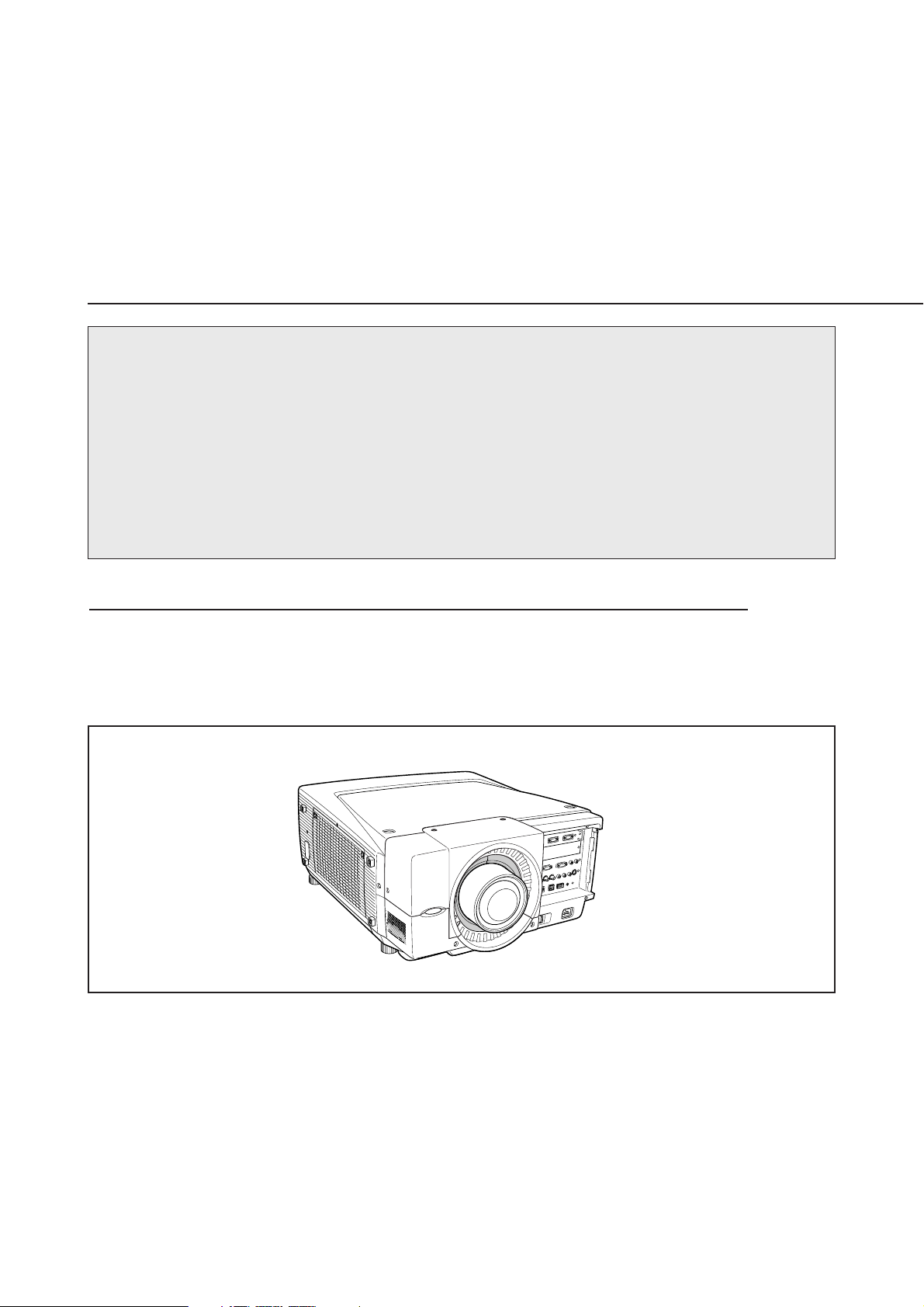
LCD PROJECTOR LENS
MODEL NO. LNS-W04/LNS-W05/LNS-W06/LNS-W07
LENS INSTALLATION
AND REPLACEMENT PROCEDURES
NOTES ON REPLACEMENT AND INSTALLATION
The procedures and the needed pars for lens installation depend on the type of
cabinet. Before installing or replacing the lens, make sure the type of cabinet of your
projector and install the lens following this procedure precisely.
When installing or replacing the lens, make sure the Lens Model No. matches with to
your projector. Refer to the catalog, or contact your sales dealer for the proper Lens
Model No.
TYPE OF THE CABINET AND INSTALLATION PROCEDURES
This manual provides the following cabinet type models.
1AA6P1P4885-- (IDZC)
※ For lens installation to the other models than below, contact your sales dealer.
Printed in Japan
Page 2

Not all the parts included may be used for lens installation or replacement. Keep these
parts for later use.
Note : Illustrations in this manual may differ from the actual product.
NOTES ON LENS INSTALLATION
• Lens installation and replacement should be made by the qualified service personnel.
• Be sure to install the lens following this procedure precisely.
• Do not touch or remove any parts except the lens and related parts. It may result
in malfunctions, electrical shock, fire hazard or other accidents.
• The lens cover is attached to the lens for protection. Be sure to remove the lens
cover from the lens before installation.
• When installing or replacing the lens, be careful not to stain, scratch or damage
its surface.
• When moving or setting up the projector, be sure to replace the Lens Cover to
protect the surface. Be careful not to hold the lens. It may damage the lens, cabinet, or mechanical parts.
After installing or replacing the lens, be sure to confirm the followings for safety.
1. Make sure the lens attachment is fixed on the lens by 4 screws.
2. Make sure the lens is fixed on the projector by lens lock lever.
3. Make sure no part is missing, or loose.
BE SURE TO CHECK THE FOLLOWING MATTERS FOR SAFETY
LIST OF CONTENTS
Following parts are included in the package.
• LENS 1 pc
• DRIVER 1 pc
-1-
Page 3

LENS REPLACEMENT AND INSTALLATION PROCEDURE
-2-
2
Pulling up Light Block Sheet Holder and Cover Plate,
remove them. (See Fig-2)
Fig-1
Front Cover
A
Fig-2
Fig-3
1
Disconnect the power cord from AC outlet.
Remove 5 screws (A) from the front cabinet.
Pulling up the front cover and remove it. (See Fig-1.)
3
Remove the cover plate from the light block sheet
holder . (See Fig-3)
A
A
Cover Plate
Light Block Sheet Holder
Cover Plate
Page 4

-3-
4
Remove lens cap on the rear (mounting side) of the projection lens and mount Lens Attachment to the
lens with four screws included with the lens.
Insert the connector at the end of Lens Motor Lead into the socket located at right-top of the lens
attachment. (With motor model only.)
Fig-4
Socket
Lens Motor Lead
Lens Attachment
Connector
Part No. (610 275 6029)
Lens Attachment
POA-LNA-04 (610 317 1289)
Locate motor on
right side.
5
Pinch Lens Lock Lever and turn it clockwise to unlock. (See Fig-5.)
Insert the Lens through the lens mounting bracket and turn the lens lock lever anticlockwise until the lens
is securely mounted. After installing the lens, make sure the Lens is not loose and properly mounted.
(See Fig-6 and Fig-7 on next page.)
Fig-5
Lens Lock Lever
Driver included with
the lens
Note : Lens Illustrations in this manual may differ from the actual product.
Note : Lens attachment is not included in this lens.
Driver included with
the lens
Part No. (610 275 6029)
Lens Attachment
Page 5

-4-
ReleaseLensLock(Clockwise)
FixLensLock(Anticlockwise)
Fig-6
Fig-7
Pinch the tab and
turn the lever
clockwise to unlock
the lens.
Pinch the tab and
turn the lever anticlockwise to lock
the lens.
CAUTION:
Turn the Lens Lock Lever anticlockwise until the lens is locked. Make sure
the lens is securely installed after installation.
Focus Lock Screw
Focus Lock Ring
FOCUS ADJUSTMENT (For Model LNS-W07)
Set up the projector and project image on the screen.
1. Loosen the Focus Lock Screw on the projection
lens.
2. Rotate the projection lens to obtain proper focus
on center area of the screen.
3. Lock the Focus Lock Screw securely.
When proper focus is not observed at outer area of
the screen, proceed following adjustments.
4. Loosen the Focus Lock Ring on the projection
lens. (Turn the Lock Ring counter-clockwise.)
5. Rotate the lens to obtain proper focus on outer
area of the screen.
6. Lock the Focus Lock Ring securely. (Turn the Lock
Ring to clockwise.)
If proper focus is not observed over the entire screen,
repeat above adjustments 1~ 6.
Page 6

-5-
6
Install Light Block Sheet and Light Block Sheet Holder corresponding to the lens into the projector. (See Fig-8 and
Fig-9.) Appropriate light block sheet varies depending on the Lens Model No. Check Type No. on the light block
sheet and Lens Model No. and use an appropriate one.
7
Replace the front cover and secure it with the 5
screws.
Fig-10
Fig-9
Light Block Sheet Holder
Light Block Sheet
Fig-8
To unfold, reverse the light block sheet and
release the latch.
q
w
Back of Light
Block Sheet
Back
Front Cover
Note: Make sure the light block sheet is fully inserted into the light block sheet holder when installing the
light block sheet and the sheet holder into the projector. Improper installation may cause the lens
malfunction.
TYPE F14A (610 315 7337)
LNS-W04/LNS-W05/LNS-W06
TYPE F14B (610 315 7320)
LNS-W07
 Loading...