

Page 1
SERVICE MANUAL LCD Television
N2YV/N2YVN/N2YVB
FILE NO.
Model No. LCD-32XL2
LCD-32XL2B
(Argentina / Brazil)
Give complete “SERVICE REF. NO.” for parts order or
servicing. It is shown on the rating label at the cabinet
back of the unit.
This T.V. receiver will not work properly in foreign countries where the television transmission
system and power source differ from the design
specifications. Refer to the specification table.
Contents
Safety Notice . . . . . . . . . . . . . . . . . . . . . . . . . . . . . . . . 2
Specifications . . . . . . . . . . . . . . . . . . . . . . . . . . . . . . . 3
Chassis Block Diagrams . . . . . . . . . . . . . . . . . . . . . . 4-5
IC Block Diagrams . . . . . . . . . . . . . . . . . . . . . . . . . . 6-8
Sub CPU Port Functions . . . . . . . . . . . . . . . . . . . . . . . 8
CPU Port Functions . . . . . . . . . . . . . . . . . . . . . . . . . . . 9
Option Setting . . . . . . . . . . . . . . . . . . . . . . . . . . . . . . 10
On-screen Service Menu System . . . . . . . . . . . . . . . 11
Initialisation of Memory IC . . . . . . . . . . . . . . . . . . . . . 12
Protection Circuit . . . . . . . . . . . . . . . . . . . . . . . . . . . . 12
Service Adjustments . . . . . . . . . . . . . . . . . . . . . . . 13-14
Mechanical Disassembly . . . . . . . . . . . . . . . . . . . 15-18
Cabinet Parts List . . . . . . . . . . . . . . . . . . . . . . . . . 19-20
Chassis Electrical Parts List . . . . . . . . . . . . . . . . 21-36
Printed Wiring Board . . . . . . . . . . . . . . . . . . . . . . 37-43
Service Ref. No. LCD-32XL2-00
LCD-32XL2B-00
LCD-32XL2B-01
-
NOTE
-
Difference between Model LCD-32XL2 and LCD-32XL2B:
1) Destination LCD-32XL2... Argentina
LCD-32XL2B...Brazil
2) Power Cord.
3) Instruction Manual.
Difference between Service Ref. No. LCD-32XL2B-00 and
LCD-32XL2B-01:
1) Country of origin
LCD-32XL2B-00... Made in Argentina
LCD-32XL2B-01... Made in Brazil
Product Code:111376316 (LCD-32XL2-00)
111376335 (LCD-32XL2B-00)
111376334 (LCD-32XL2B-01)
Original Ver sion
Chassis Series: UE2-B
P
Page 2
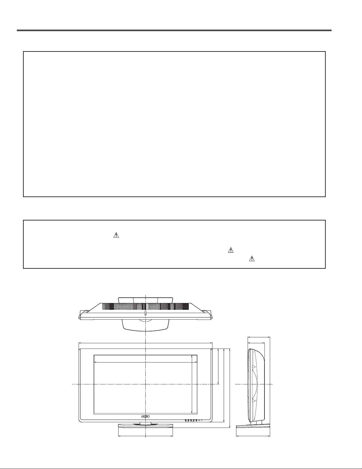
377
245
506
545
922
711
401
233
115
153
(Unit : mm)
Safety Notice
-2-
Safety Precautions
The following precautions must be observed.
1: Comply with all caution and safety-related notes provided on the cabinet back, cabinet bottom, inside the
cabinet or on the chassis.
2: When replacing a chassis in the cabinet, always be certain that all the protective devices are installed
properly, such as, control knobs, adjustment covers or shields, barriers, etc..
DO NOT OPERATE THIS TELEVISION WITHOUT THE PROTECTIVE SHIELD IN POSITION AND PROPERLY
SECURED.
3: Before replacing the cabinet cover, thoroughly inspect the inside of the cabinet to see that no stray parts or
tools have been left inside.
Before returning any television to the customer, the service personnel must be sure that it is completely safe to
operate without danger of electrical shock.
Product Safety Notice
Product safety should be considered when a component replacement is made in any area of a receiver.
Components indicated by mark in the parts list and the schematic diagram designate components in which
safety can be of special significance. It is particularly recommended that only par ts designated on the par ts list
in this manual be used for component replacement designated by mark . No deviations from resistance
wattage or voltage ratings may be made for replacement items designated by mark .
[ Details of Dimensions ]
Page 3

Specifications
-3-
Power Source AC100-240 Volts, 50/60Hz
Receiving System PAL-N/N/, PAL-M/M, NTSC-M/M
Channel Coverage ANTENNA mode
VHF: CH02 - CH13
UHF: CH14 - CH69
CATV mode
VHF band: CH01-CH13
MID band: CH14-CH22
SUPER band: CH23-CH36
HYPER band: CH37-CH64
ULTRA band: CH65-CH94 and CH100-CH125
Low MID band: CH95-CH99
Aerial Input Impedance 75 Ω
LCD Panel
Screen Size (Measured Diagonally): 32 inches
Picture Resolution: WXGA 1366 (Horiz.) x 768 (Vert.) pixels
Viewing Angles: Horiz. 176˚, Vert. 176˚
Contrast Ratio: 1000:1
Brightness: 550 cd/m
2
Audio Output (RMS) 10W+10W
Speakers 6 cm x 12 cm x 2 pcs.
AV Terminals
AV1 Video: Composite video Input (RCA Jack) x 1
Audio: L/R Stereo Input (RCA Jack) x 1 set
AV2 CENELEC Standard (Scar t Terminal)
Input: Composite video, RGB, S-video and audio-L/R
Output: Monitor-output with composite video and audio-L/R
AV3 Video: Composite video Input (RCA Jack) x 1
Audio: L/R Stereo Input (RCA Jack) x 1 set
AV4 Video: Composite video Input (RCA Jack) x 1
Audio: L/R Stereo Input (RCA Jack) x 1 set
AV5 Video: Component Y , CB,CR Input (RCA Jack) x 1 set
Audio: L/R Stereo Input (RCA Jack) x 1 set
Audio Monitor Output: L/R Stereo Output (RCA Jack) x 1 set
Headphone Jack: Mini Stereo Jack x 1
Dimensions: 922 (W) X 545 (H) X 233 (D) mm (Included Tilt Stand)
Weight 17.5 kg (Included Swivel Stand)
Specifications subject to change without notice.
Page 4
-4-
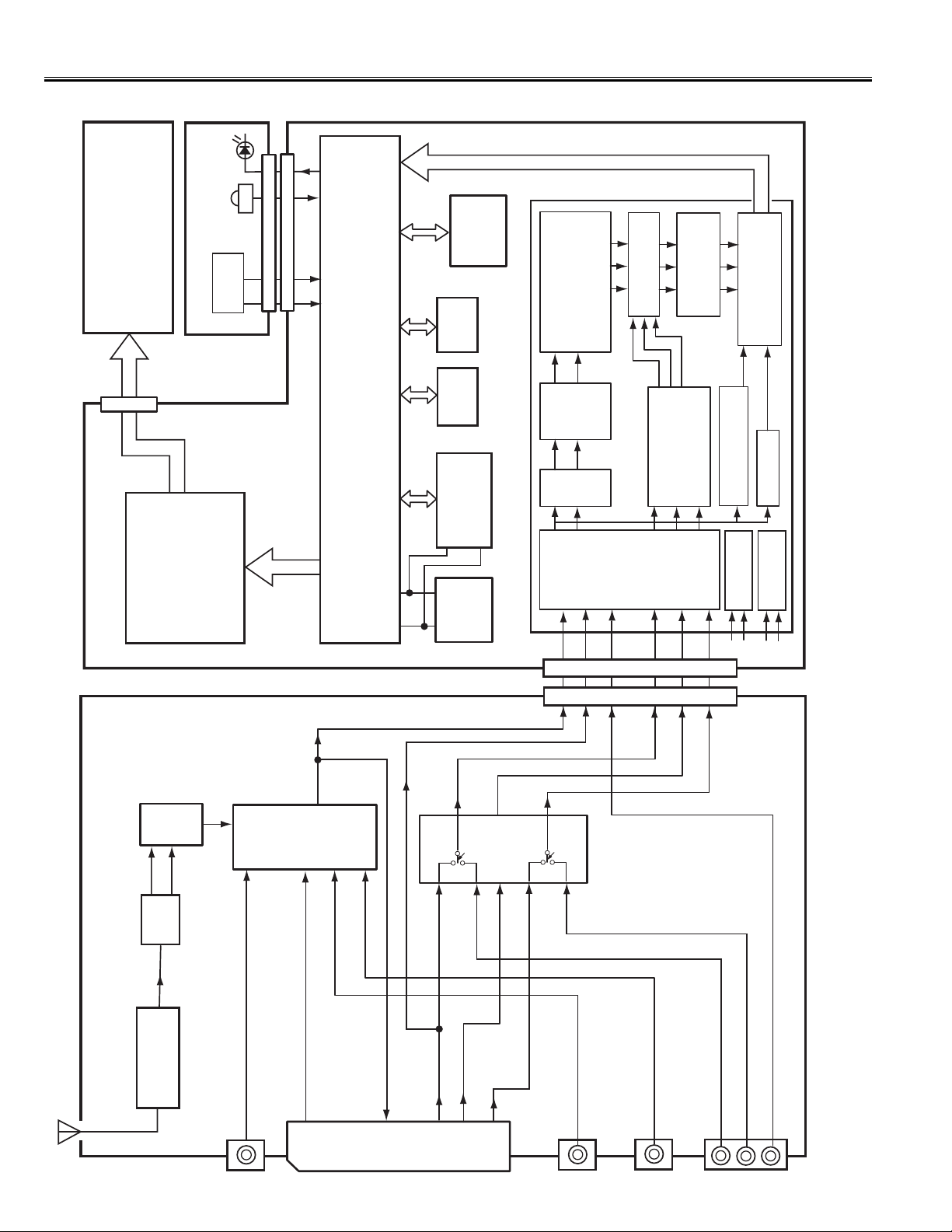
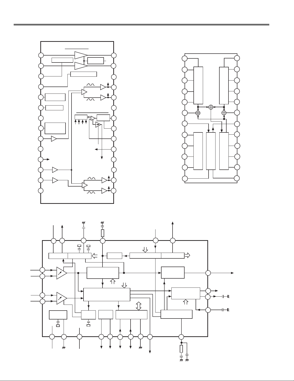
Chassis Block Diagrams (Video Signal Lines)
LED
D3901
117~124
IC805
IC803
SDRAM
FLASH
MEMORY
(WXGA)
LCD PANEL
A3901
RC RECEIVER
ASSY,PWB, CONTROL
SW3951~
SW3955
K19J
K8J
RC-IN
KEY IN
POWER
KEY IN
132
145
146
PAL/NTSC/SECAM
Standard Identifier
& Chroma Demodulator
DIGITAL
Y, CB, CR
OUTPUT
Pin-19~28
Soft Mixer
Video Corection
& Output Scaler
Format Converter
Output FIFO
Line-locked Output Pixel Clock
KLP1 (27")
KLP2 (32")
ASSY, PWB, SCAL
IC101
IF-PLL
(TDA9886)
DEMODULATOR
IC4001
1
VIF1
VIF2
32":77~86
27":90~99
(ADE3800)
(SCALER/LVDS)
ANALOG LCD
DISPLAY ENGINE
TV
17
2
OUTPUT
ANALOG PB/B, PR/R, Y/G
33/34/38/39/43/44
VIDEO OUT
SELECTED
16
IC1224
VIDEO SW
12
7
IC801
153/154/155
1
5
IC804
SDRAM
(STV3600)
MAIN CPU/CAPTION DECODER
IC1801
SUB CPU
1
SCL
3
4
20
6
IC802
5
MEMORY
SDA
R
R/C
S-VIDEO-C IN
G IN
3
5
3
16
1
14
DIGITAL VIDEO DECODER
IC2001
(STV2310)
K8D
KD
B/CB
6
8
Luma
Input
CVBS IN
63
26
15
9
Chroma
Separator
SRC
C IN
3
14
27
IC1251
Analog
Y IN
2
29
12
RGB SW
RGB Insertion
Input Stage
R/CR IN
51
52
23
22
18
19
G IN
Synchronization
B IN
B/C
53
24
17
& Monitoring Unit
VBI Slicer
C Interface
generation
2
I
System Clock
X121
ASSY, PWB, SIGNAL
SAW
IF
A101
FILTER
TUNER
AV1 VIDEO IN
COMPISITE VIDEO IN
AV1 TERMINAL (K1001)
AV2 VIDEO IN
COMPISITE VIDEO/Y IN
20
AV2 SCART (K1002)
B IN (AV2)
CB IN (AV5)
COMPISITE VIDEO IN
AV3 TERMINAL (K1003)
COMPISITE VIDEO IN
AV4 TERMINAL (K1004)
COMPONENT CR IN
AV5 TERMINAL (K1006)
B IN
COMPONENT Y IN
COMPONENT C
19
R IN (AV2)
R/S-VIDEO C IN
15
G IN
11
CR IN (AV5)
G/Y IN (AV2)
B IN
7
AV4 VIDEO IN
AV3 VIDEO IN
VIDEO MONITOR OUT
Page 5
-5-
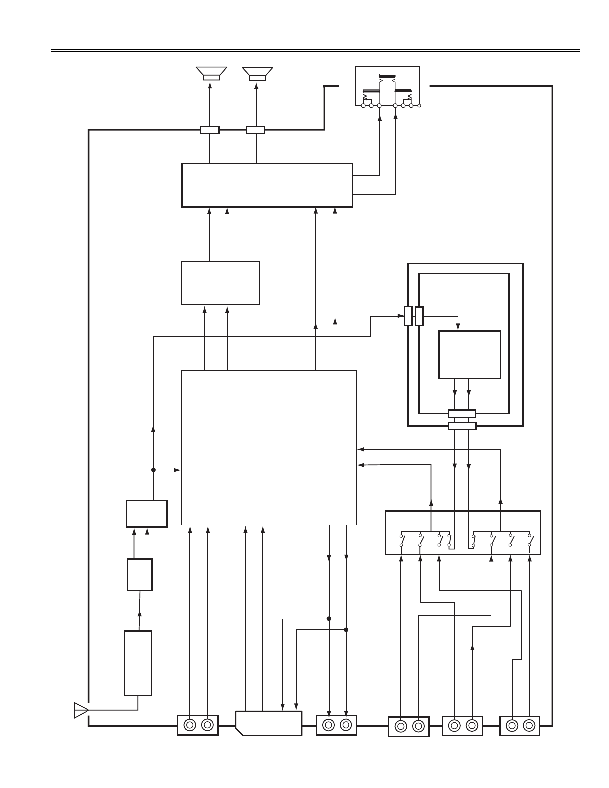
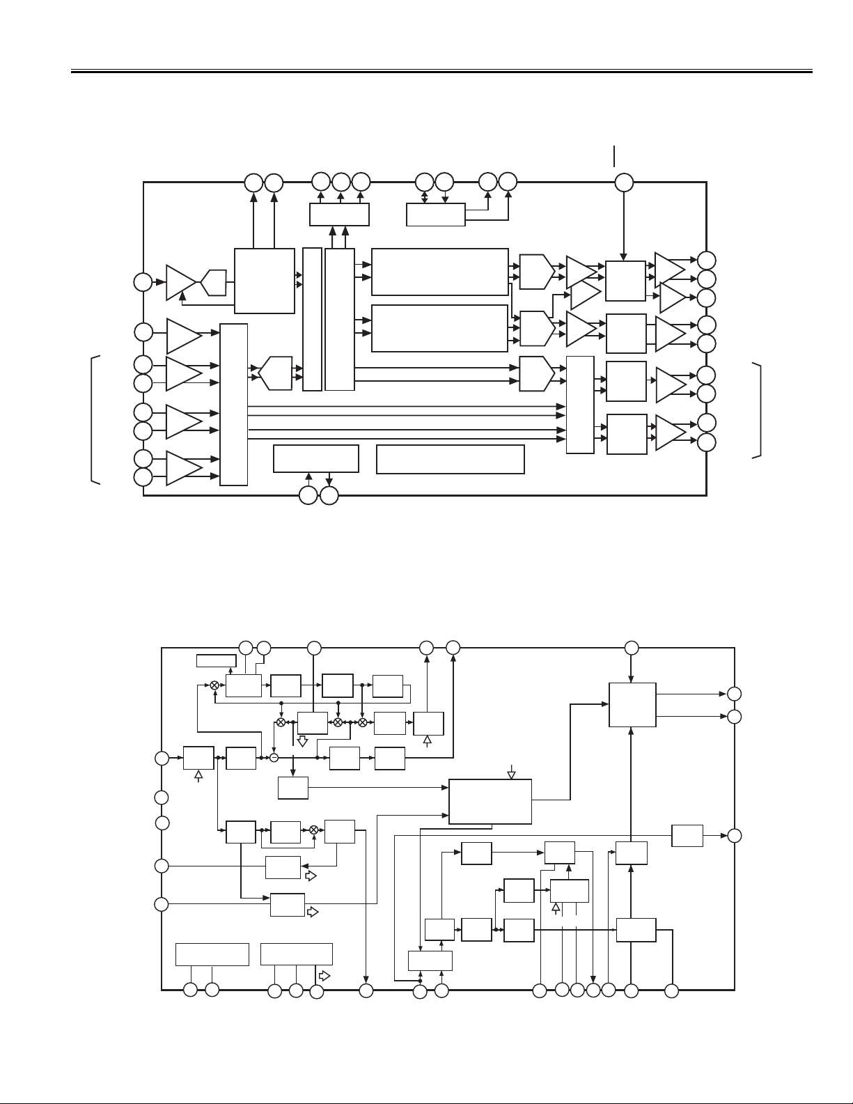
Chassis Block Diagrams (Audio Signal Lines)
IC001
(LA4919N)
AUDIO AMP.
IC3501
(NJM2155)
BBE/BASS EXPANDER
SP901
KSPL
L-OUT
15/16
13
AUDIO L-OUT
6
1
L-OUT
AUDIO
28
SP902
KSPR
9
AUDIO R-OUT
19
24
R-OUT
AUDIO
29
R-OUT
24/25
K001
HEADPHONE JACK
L-OUT
28
1
HEADPHONE L-OUT
31
27
2
R-OUT
HEADPHONE R-OUT
29
KIF
K36IF
TV
IC3601
(CXA2104S)
AUDIO-IN
11
2
1
MTS
ASSY, PWB,
MTS / SAP
ASSY, PWB, SIGNAL
IC101
IF-PLL
(TDA9886)
DEMODULATOR
X122
23
SIF1
SAW
IF
A101
TV AUDIO OUT
8
24
SIF2
FILTER
TUNER
TV OUT-L
TV OUT-R
K36P3
L-OUT
3
5
AV4 L-IN
KP3
2
AV5 L-IN
TV -L
4
TV -R
11
R-OUT
13
12
AV3 R-IN
14
AV4 R-IN
15
AV5 R-IN
R-IN
IC3451
78
9
10
(STV8216)
14
3D SURROUND
AUDIO PROCESSOR/
STEREO SOUND DEMODULATOR/
15
24
23
L-IN
18
19
IC1222
AUDIO SW
1
AV3 L-IN
AUDIO MONITOR OUT-L
AUDIO MONITOR OUT-R
AUDIO L-IN
AV1 TERMINAL (K1001)
AUDIO R-IN
AUDIO L-IN
6
AV2 SCART (K1002)
AUDIO R-IN
AUDIO MONITOR OUT-L
2
3
AUDIO MONITOR OUT-R
1
(K1005)
AUDIO MONITOR OUT
AUDIO L-IN
AV3 TERMINAL (K1003)
AUDIO R-IN
AV4 TERMINAL (K1004)
AUDIO L-IN
AUDIO R-IN
AUDIO L-IN
AV5 TERMINAL (K1007)
AUDIO R-IN
Page 6
-6-
IC001 < AUDIO AMP. > LA4919N-E
IC Block Diagrams
2
1
3
4
6
5
7
8
10
9
12
13
14
17
18
19
20
21
22
23
26
HP IN1
Headphone Block
27
Ripple filter
Ripple filter
Voltage
Regulator
Vcc
28
VG=6dB
VG=6dB
H/P Standby SW
15
16
A
B
AMP. Standby
SW
Output
amplifier
Output
amplifier
Nonlinear
amplifier
24
25
Muting circuit
used at power
on
Intput
amplifier
H. L. S
Switching regulator Block
Switching
Drive
ABC
D
*H. L. S
Higher Level
Signal Selector
Headphone stage
Input amplifier stage
Switching regulator stage
Power TR stage
VCC
C
D
Output
amplifier
Output
amplifier
Nonlinear
amplifier
OUT1+
OUT1
-
Output amplifier
stage
11
REF amplifier
Input amplifier
HP IN2
HP OUT2
HP OUT1
HP D.C
HP Standby
AMP Standby
D.C
DDL
ON TIME
IN2
PRE GND
PRE VCC
IN-VREF
IN1
POWER GND
POWER GND
SW GND
SWB
SWE
SW OUT
OUT2
+
OUT2
-
IC101 < IF-PLL Demodulator > TDA9886TSV4P
VIF2
TUNER AGC
VIF-AGC
SIF AGC
OUTPUT
PORTS
I2C-BUS TRANSCEIVER
SINGLE REFERENCE QSS MIXER
INTERCARRIER MIXER
AND AM DEMODULATOR
VIF-PLL
RC VCO
DIGIT AL VCO CONTROL
AFC DETEVTOR
SOUND TRAPS
4.5 to 6.5MHz
AUDIO PROCESSING
AND SWITCHES
NARROW-BAND
FM-PLL DEMODULATOR
SUPPLY
MAD
1
2
3
4
6
5
7
8
10
9
12
13
14
11
17
18
19
20
21
22
23
15
16
24
VIF1
SIF2
SIF1
Vp
AGND
N.C.
OP1
OP2
SCL
SDA
DGND
SIOMAD
Sound intercarrier output
and MAD select
FM-PLL
FM-PLL filter
c
AGC
c
AF
de-emphasis
network
c
AF
DEEM
AUD
Audio output
CVBS
Video output: 2Vp-p
(1.1vp-p without trap)
VPLL
REF
AFC
External reference signal
or 4MHz crystal
VIF-PLL filter
VAGC
c
VAGC
(pos)
TOP
TAGC
c
AGC(neg)
c
BL
IC3501 < BBE/Bass Sound Processer >
NJM2155M
2
1
3
4
6
5
7
8
10
9
12
13
14
17
18
19
20
21
15
16
11
LOWOUT-L
OUT-L
Vcc
IN-L
FILTER
MACH3
HOUT-L
LOWIN-L
IN-R
HIN-R
HOUT-R
22
23
24
HIL-L
BBE
BBE
Mach3
Bias
Control
LOWIN-R
LOWOUT-R
OUT-R
VREF
GIN
GOUT
LPIN
LPOUT
GND
BBE
PROCESS
LO CONTOUR
Page 7
-7-
IC Block Diagrams
IC3601 < MTS Decoder > CXA2104S
2
1
3
4
6
5
7
8
10
9
12
13
14
17
18
19
20
21
MAIN IN
27
15
16
11
MAIN OUT
SAP IN
ST IN
SUB OUT
PCINT1
COMP IN
Vcc
PLINT
PCINT2
NOISETC
SAPTC
SAP OUT
IREF
VGR
DGND
SCL
SDA
30
LPF
MATRIX
VCA
RMSDET
RMSDET
SPECTRAL
VE
HPF
LPF
LPF
DeEm
AMP
(+4dB)
SW
LOGIC
NRSW/FOMO/SAPC
IREF
I
2
C BUS I/F
LPF
BPF
SAPVCO
SAPIND
NOISE
DET
"PONRES"
"SAP"
"NOISE"
VCA
WIDE BAND
1/2
LPF
LPF
LPF
STIND
DeEm
VCA
VCO
1/4
LFLT
STLPF
FLT
ATT/INSW
(+6dB)
"STEREO"
VE
VEWGT
VETC
VEOUT
VCAIN
VCAWGT
VCATC
TVOUT-L
TVOUT-R
SOUT
22
23
28
24
25
26
GND
IC3451 < Audio processor > STV8216
2
1
10
9
14
18
19
15
MONO IN
62
SIF
23
28
24
Sound IF
73
78
AL1L
AL1R
AL2L
AL2R
AL3L
AL3R
Input Scarts
0.5V
rms
2V
rms
2V
rms
2V
rms
Audio
Stereo
A/D
Input Analog Audio Matrix
AGC
A/D
Multi-Standard
Digital Stereo
Demodulator
FM, AM, A2
& NICAM
Demodulation
69
52
IRQ
ST
Interrupt
Request
Stereo
Flag
Source preprocessing
Stereo
Flag
Digital Audio Matrix
I2S Interface
I2C Interface
63
61
SDO
WS
64
WS
40
39
SDA
SCL
BUS0
(BBE)
68
65
BUS1
(MACH-3)
HPD
35
Headphone
Detection
Audio Processing
Loudspeaker Audio Processing
Smart Volume Control, ST Wide
Surround, 5-band Equalizer &
Loudness, Beeper & Subwoofer Out
Headphone Audio Processing
Smart Volume Control,
Bass/Treble & Beeper
Audio Matrixing
Signal Crystal
Clock generation
Power Supply Management
DC Regulators, Standby mode
XTI
XTO
30
53
LSL
LSR
SW
HPR
AO1L
AO1R
Audio
Stereo
D/A
Audio
Stereo
D/A
Audio
Stereo
D/A
Vol.
Bal
Gain
Vol.
Bal
Output Analog
Audio matrix
Low Noise
Audio
Mute
Low Noise
Audio
Mute
Low Noise
Audio
Mute
Low Noise
Audio
Mute
1V
rms
2V
rms
2V
rms
Loudspeaker
AO2L
AO2R
HPL
29
1V
rms
32
31
I2C Bus Expander
Headphone
Output Scarts
Sub woofer
Page 8
-8-
IC Block Diagrams
Pin No. Function Name Function
1 SCL I2C Bus Clock (For Tuner, IC101, IC3451 of Signal Unit)
2 P3_7 TV_VGA (Not used)
3 Reset Reset Input (L=Reset)
4 Xout X’tal Osc. Output (10MHz)
5 Vss Vss (GND)
6
Xin
X’tal Osc. Input (10MHz)
7 Vcc Vcc=3.3V
8 Mode Mode / Connected to Vcc
9 P4_5
10 P1_7 A Detection Input (Not used)
11 P1_6 DM Clock Output (Not used)
12 P1_5 DM Data (Not used)
13 P1_4 DM IR Send (Not used)
14 P1_3 RGB ON/OFF Output (Not used)
15 P1_2 Power4 Output
16 Vref Reference for ADC (Vcc)
17 P1_1 Timer Recording Output (H=Recording) (Not used)
18 P1_0 D/A Control Output (H=Digital)
19 P3_3
20 SDA I
2
C Bus Data (For Tuner, IC101, IC3451 of Signal Unit)
Sub CPU Port Functions (IC1801)
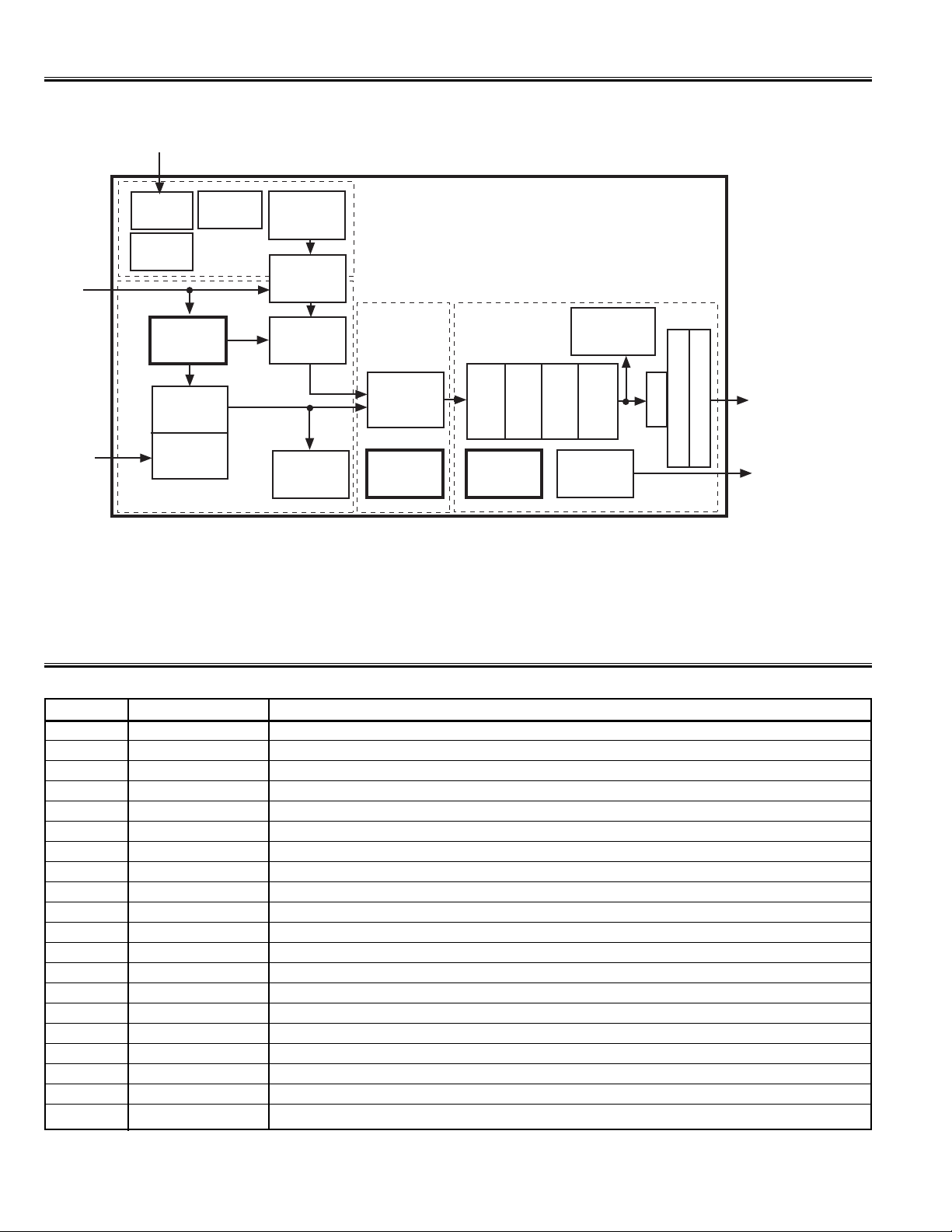
IC4001 < Analog LCD Display Engine > ADE3800
Analog
H&V
Syncs
GLBL
GLobal
Control
MCU (SCL, SDA)
I2C
PWM
Pulse Width
Modulation
SMEAS
Sync
Measure
SRT
Sync
Retiming
XCLK
Domain
Analog
R,G,B
Data
INCLK
Domain
SCLK
Domain
DCLK
Domain
Out Data
Syncs & Clock
(To LCD Panel)
TCON
LLK
Line Lock
PLL
ADC
(Digital)
ADC
(Analog)
SMUX
Sync
Multiplexer
DMEAS
Data
Measure
SCL
Scaler
SCLK
PLL
DCLK
PLL, FM
FLK
Flicker
Detection
TCON
Timing
Controller
PGEN
Pattern
Generator
sRGB
GAM
Gamma
OSD
On-Scree
Display
APC
OMUX Output multiplexer
LVDS_RSDS
Page 9

-9-
Main CPU Port Functions (IC801)
Pin No. Port Name Function
131 A0 N_Reset Output (Active=H)
133 A1 Power error-1 input
10 A2 PLL Lock
11 A3 LCD Brightness Output
135 A4 LED / For software flash
136
A5
Audio Mute / For software flash
137 A6 Control of Inverter (Active=L)
138 A7 For writing / FAN Control Check (For manufacturing process) (Active=L)
146 B0 Power ON/OFF Switch Input (AD Input)
145 B1 Key Board Input (AD Input)
144 B2 8-pin of Scart-1 Input (AD Input) -Not used143 B3 8-pin of Scart-2 Input (AD Input)
142 B4 8-pin of Scart-3 Input (AD Input) -Not used141 B5 AGC Input
130 C0 SDA for ADE3800 (IC4001)
129 C1 SCL for ADE3800 (IC4001)
128 C2 AV Switch-C Output
127 C3 Power-3 Output
4C4SDA for EEPROM (IC802)
3C5 SCL for EEPROM (IC802)
2C6SDA for device other than EEPROM
1C7 SCL for device other than EEPROM
5D0AV Switch-A Output
6D1 LCD ON (Back-Light ON/OFF) Output
7D2 50/60Hz Switch (Switching PAL/NTSC) Output
8D3AV Switch-B Output (Active=H)
132 D4 RC Input (Active=L)
147 D5 Power Switch-1 output
9D6Power error-2 Input
134 D7 Power Info. Input (Input of the power supply condition)
Page 10
P
Option Setting
-10-
After replacing Memory IC (IC801)
The memory IC (IC802) stores the option data of TV set and service adjustments data for each circuit, therefore, when
the memory IC is replaced, it should be programmed to the following settings and “ Service Adjustment” on page 13-
14.
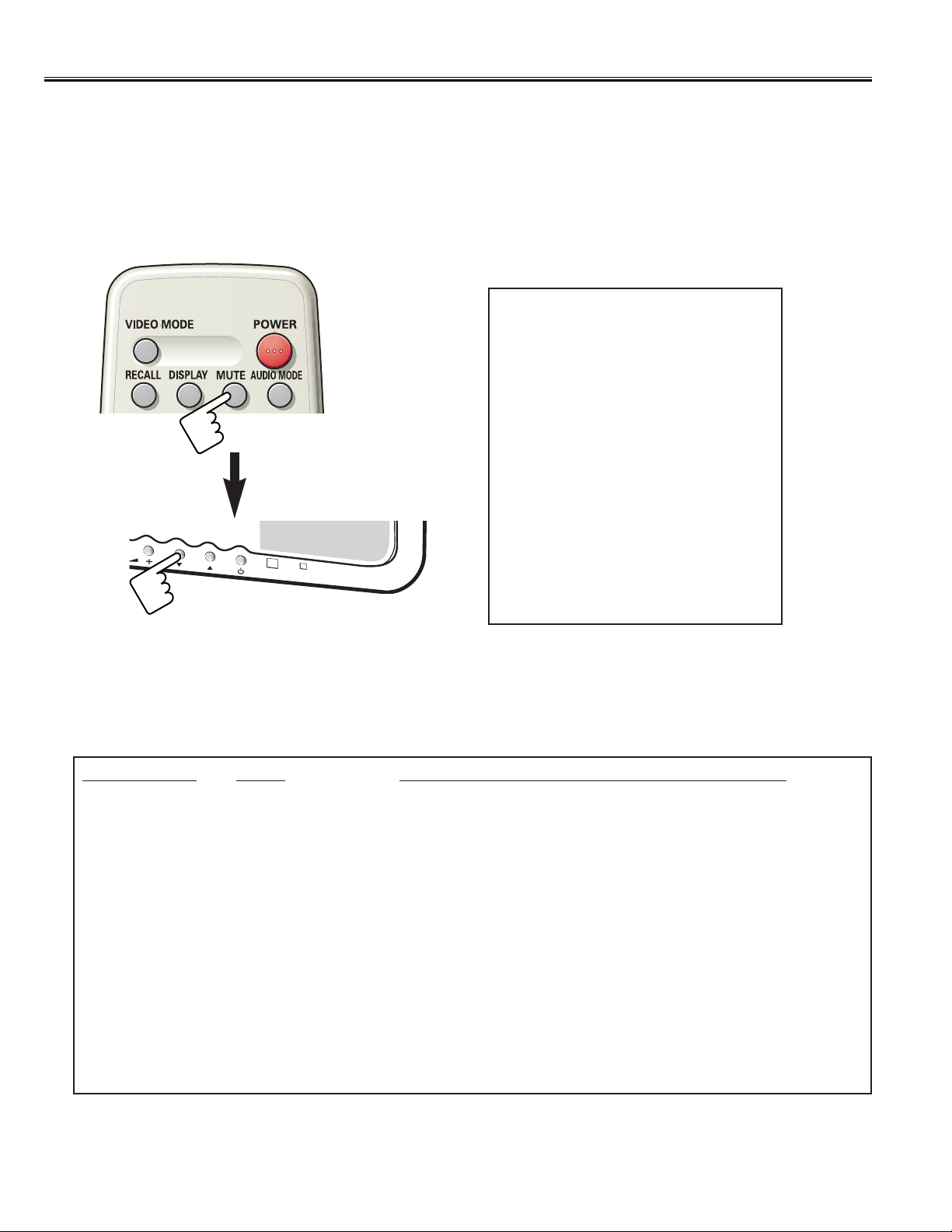
1) How to enter the Option Setting Mode
Press and hold the MUTE button on the remote control and press the CHANNEL DOWN (P▼)button on the front
control panel of the TV. The option window will appear on the screen.
[ Option Setting Menu ]
2) How to make the Option Setting
Select desired option item by pressing the CHANNEL UP or DOWN button.
To switch the option mode, use the VOLUME + or -button.
The data which is set in the option mode is stored into the memory IC automatically.
The following table shows the available option items and default setting mode.
Option Items Mode Default / Description
ON Timer ON or OFF Default “OFF”/ Disable or enable ON Timer function.
Plug & Play ON or OFF Default “ON”/ Disable or enable Plug & Play function.
Welcome Text ON or OFF Default “ON”/ Display message when first set up.
BBE ON or OFF Default “ON”/ Disable or enable BBE function on Sound menu.
Auto Volume ON or OFF Default “ON”/ Disable or enable “Auto Volume Level” function
on Sound menu.
Bass Expander ON or OFF Default “ON” / Disable or enable Bass Expander on Sound menu.
16:9 Mode ON or OFF Default “ON”/ 16:9 mode.
Noise Reduction ON or OFF Default “ON” / Disable or enable Noise Reduction function on
Setting menu.
Country UK. UK&IRE or EU Default “EU”/ Selection of TV system.
Raster Rotation ON or OFF Default “OFF” / Disable or enable Raster Rotation function.
SESA ON or OFF Default “OFF”.
Digital RC ON or OFF Default “OFF” / Disable or enable use of Digital RC hand-set.
Light Monitoring ON or OFF Default “OFF” / Disable or enable Light Monitoring function.
Video Mute ON or OFF Default “OFF” / Disable or enable Video Mute function.
3) Exit from the Option Mode
Press the MENU button or turn off the TV set by pressing the Power ON/OFF button.
ON Timer OFF
Plug & Play ON
Welcome T ext ON
BBE ON
Auto Volume ON
Bass Expander ON
16:9Mode ON
Noise Reduction ON
Country EU
Raster Rotation OFF
SESA OFF
DIGITAL RC OFF
Light Monitoring OFF
Video Mute OFF
Page 11
On-screen Service Menu System
-11-
General
This set has an On-screen Service Menu system included in the CPU that allows remote operation for most of the
service adjustments.
3) Exit from the Service Menu
Press the MENU button repeatedly or turn off the TV set by pressing the Power ON/OFF button.
2) How to select the service section and service item and change data value:
To select Service Section: Press the Cursor or button on the remote control hand set, and press the
VOLUME + button to enter the Sub menu.
To change data value: Select ser vice item by pressing the Cursor or
,
and change data value by pressing
the VOLUME + or
-
button.
(To retur n to the Main menu, press the MENU button.)
On-screen Service Menu System
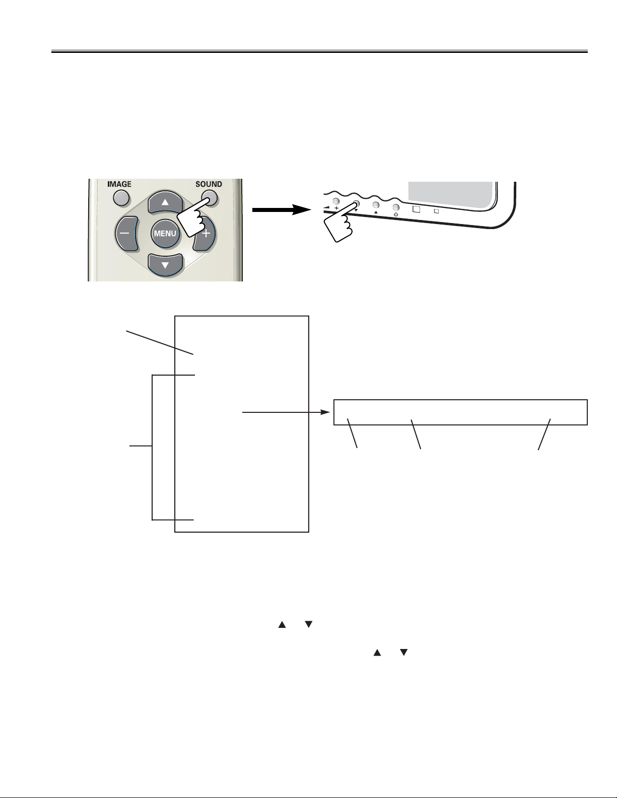
1) How to enter the Service Menu
Press and hold the SOUND button of the remote control and press the CHANNEL DOWN (P▼)button on the front
control panel of the TV, and the Main menu of service mode will be displayed.
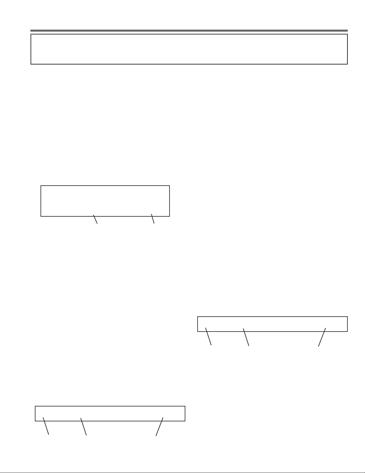
[ Main Menu of the Service Mode ]
Software Version
Information
Service Section
P
Service
ue2b27v7.01s128
Sound
Video
OOtthheerr
STV8216
TDA9886
STV2310
ADE3800
WSS
EEPROM Reset
55 White BalR 32
[Sub Menu]
Data V alue
Item No.
Example;
Important Notice: Do not attempt to adjust service adjustments not listed on page 13-14, otherwise it may
cause loss of performance and for correct operation.
Item
Page 12

Initialisation of Memory IC (IC802)
-12-
Protection Circuit
How to Initialise the Memory IC
To initialise the Memory IC (IC802), press and hold the IMAGE button on the remote control, then press the
CHANNEL DOWN button on the front panel of the TV set and then turn the Mains switch off and on.The initialisation is
now completed.
When initialised the memory IC and all of the setting data (option data and service adjustment data) stored in the IC
are reset to the default value. It is necessary to set the option settings and readjust the ser vice adjustments listed on
page 13-14 and to re-tune all the channels.
This TV set has a built-in power supply protection circuit.
It is provided to protect the TV set in case of a power supply circuit malfunctions.When something abnormality occurs
during TV reception, the TV set goes to the stand-by mode.
When operating the Protection Circuit, the Stand-by and Power Indicator will blink.
Releasing the protective circuit and restoring power supply
To release the protective circuit and restore power supply, disconnect the AC cord for a short time. This will work only
if the power supply trouble was temporary. If there is per manent trouble such as a damaged circuit, power cannot be
restored and the circuit will have to be repaired.
Page 13
-13-
Service Adjustments
Important Notice:
Do not attempt to adjust service adjustments not listed below otherwise it may cause loss of performance and for
correct operation.
AGC Adjustment
1. Receive PAL-N colour bar pattern.
(ANT Input Level:62dBµV 75 ohms terminated)
2. Connect a Digital Volt Meter to Tuner-AGC terminal
(TP-A) and the ground.
3. Enter the Ser vice Mode, and select item TDA9885
with ▲ or ▼ key.
4. Select item Write 1 of TDA9885 with ▲ or ▼ key.
5. Adjust voltage of Tuner-AGC to become 3.2V±0.3V DC
with VOLUME + or -key .
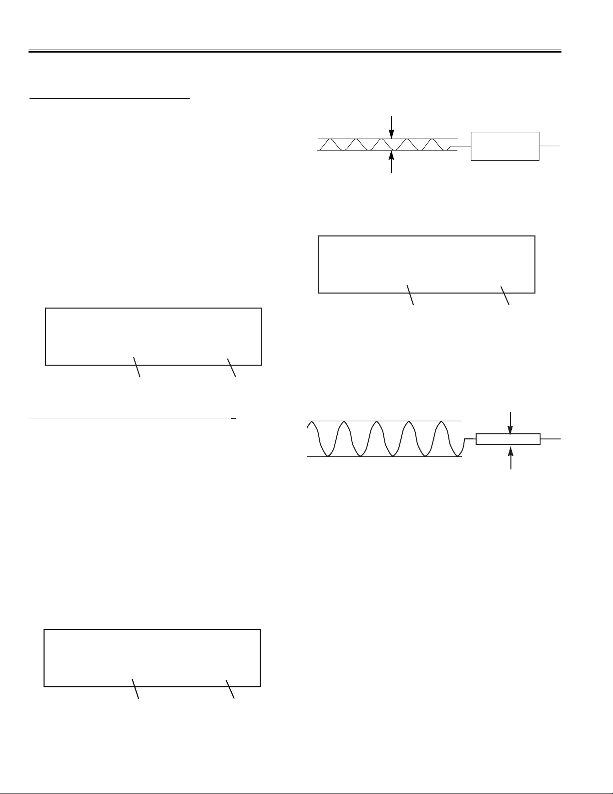
White Balance Adjustment
[ Setting ]
1. Connect a color-bar generator to the external
(composite) video input terminal (AV1 or AV3), and
input a White Pattern (90%).
2. Set the television to following conditions:
Picture Mode: Dynamic
Pre-heating Time:More than 10 minutes
[ White Balance Adjustment ]
1. Enter the Ser vice Mode, and select item “Other”
with ▲ or ▼ key, then press the VOLUME + or - key
to enter the Sub menu.
Adjustment Item:
No. 55 White Balance R
No. 56 White Balance G
No. 57 White Balance B
2. Set
55 White BalR, 56 White BalG
and
57 White BalB
value to “32”with VOLUME + or - key .
TDA9885 FE
Write 1 10
Data V alue
Item No.
Black Balance Adjustment
[ Setting ]
1. Connect a color-bar generator to the external
(composite) video input terminal (AV1 or AV3 ter minal),
and input a dark gray pattern (10% white).
2. Set the television to following conditions:
Picture Mode: Dynamic
Pre-heating Time:More than 10 minutes
[ Black Balance Adjustment ]
1. Enter the Ser vice Mode, and select item “Other”
with ▲ or ▼ key, then press the VOLUME + or - key to
enter the Sub menu.
Adjustment Item:
No. 58 Black Balance R
No. 59 Black Balance G
No. 60 Black Balance B
2. Set 58 Black BalR, 59 Black BalG and 60 Black
BalB value to “255” with VOLUME + or - key .
3. Decide one item in three items to a fixed value
(Example, let 58 Black BalR be fixed value), select
item of other 2 colors (Example, 59 Black BalG or
60 Black BalB) with ▲ or ▼ key, and adjust to
produce a normal black and white picture in dark gray
areas with VOLUME + or -key .
(Note: At this time, Adjust the other 2 colors data less
than fixed data.)
After adjustment, confirm white balance again by
normal picture.
58 Black BalR 255
Data V alue
Item No.
Item
55 White BalR 32
Data V alue
Item No.
Item
3. Decide one item in three items to a fixed value
(Example, let 55 White BalR be fixed value), select
item of other 2 colors (Example, 56 White BalG or 57
White BalB) with ▲ or ▼ key, and adjust to produce a
normal black and white picture in highlight areas with
VOLUME + or - key .
(Note: At this time, Adjust the other 2 colors data less
than fixed data.)
After adjustment, confirm white balance again by
normal picture.
Page 14
Service Adjustments
-14-
Minimum leakage
Pin-1 of K36P3(R)
300Hz
MTS Adjustment
Input Level Adjustment
[ Setting ]
1. Connect a Digital Volt Meter to Pin-1 of K36P3 on the
MTS unit and the ground.
2.
Receive the channel with audio 1KHz 100% modulation
signal.
3. Set the television to following conditions:
Audio Mode: Stereo
Surround and BBE: OFF
[ Adjustment ]
1. Enter the Ser vice Mode, and select item “CXA2104”
with ▲ or ▼ key, then press the VOLUME + or
-
key
to enter the Sub menu.
2. Select item Write 0 of CXA2104 with ▲ or ▼ key.
3. Adjust voltage to become DC 400mVrms±30% by
pressing the VOLUME + or
-
key .
CXA2104 0
Write 2 20
Data V alue
Item No.
3. Adjust the level of 300Hz at
Pin-1 of K36P3
to become
minimum level by pressing the VOLUME + or-key .
Pin-3 of K36P3 (L)
Minimum leakage
4KHz
4. Select item Write 1 (High Separation Adjustment) of
CXA2104 with ▲ or ▼ key.
5. Adjust the level of 4KHz at
Pin-3 of K36P3
to become
minimum level by pressing the VOLUME + or-key .
6. Repeat steps 2 to 5 for best separation.
CXA2104 0
Write 1 20
Data V alue
Item No.
CXA2104 0
Write 0 7
Data V alue
Item No.
Stereo Separation Adjustment
[ Setting ]
1. Connect an oscilloscope:
Probe-A to Pin-1 of K36P3 and the ground.
Probe-B to Pin-3 of K36P3 and the ground.
2.
Receive a MTS channel.
3. Set the television to following conditions:
Audio Mode: Stereo
Surround and BBE: OFF
[ Adjustment ]
1. Enter the Ser vice Mode, and select item “CXA2104”
with ▲ or ▼ key, then press the VOLUME + or - key
to enter the Sub menu.
2. Select item Write 2 (Low Separation Adjustment) of
CXA2104 with ▲ or ▼ key.
Page 15
-15-
Mechanical Disassembly
AV1
AV2
AV3
A
U
D
IO
M
O
N
ITO
R
O
U
T
L
R
AV5
Y
C
B
C
R
AUDIO
L
R
L
R
V
ID
E
O
L
R
V
ID
E
O
DVD INPUT
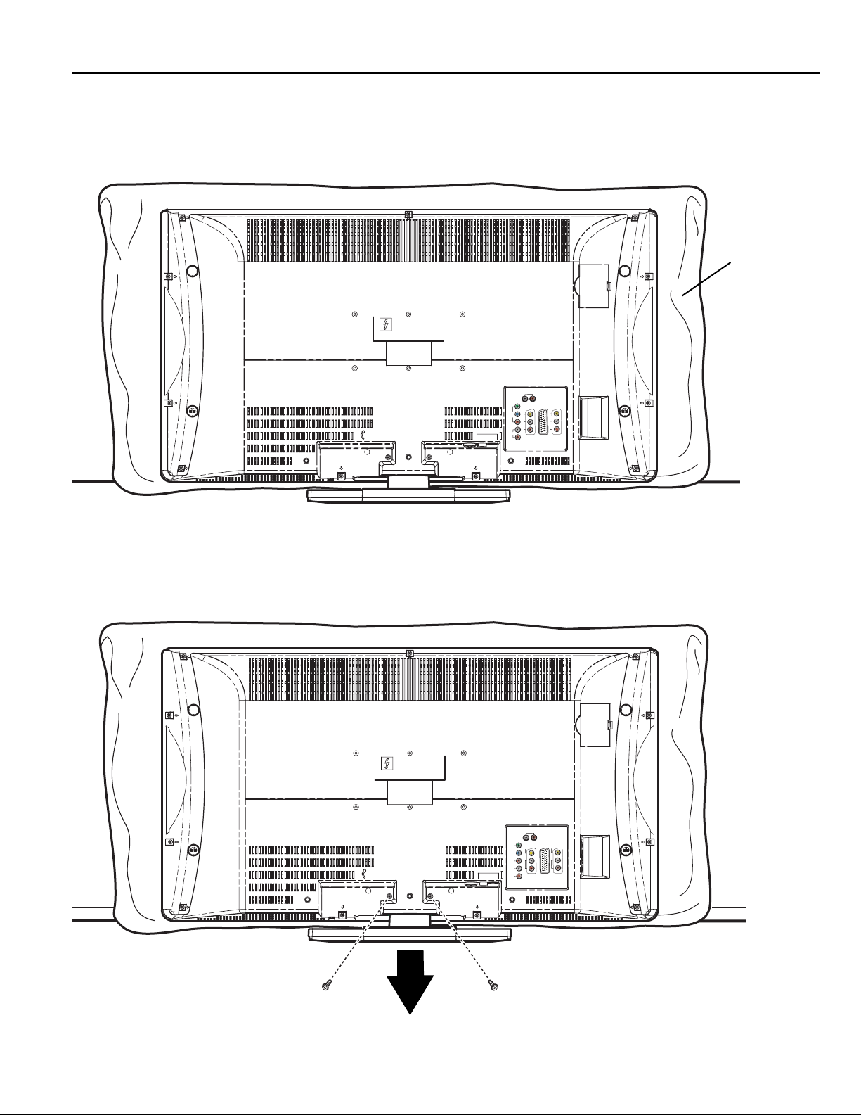
1. Stand Removal
1. Position TV face down on a padded or cushioned surface to protect the screen and finish.
2. Remove 2 screws and pull the stand in the direction of the arrow to remove.
AV1
AV2
AV3
A
U
D
IO
M
O
NIT
O
R
O
U
T
L
R
AV5
Y
C
B
C
R
AUDIO
L
R
L
R
V
ID
E
O
L
R
V
ID
E
O
DVD INPUT
Cushion
Page 16

-16-
Mechanical Disassembly
2. Cabinet Back Removal
Remove 11 screws and take the Cabinet Back off.
Note: Cabinet Back can be removed even if it does not remove a stand.
Y
C
B
C
R
L
AUDIO
R
DVD INPUT
AUDIO MONITOR OUT
L
O
E
VID
L
R
AV5
R
EO
ID
V
L
R
AV1
AV2
AV3
Page 17

-17-
Mechanical Disassembly
3. Chassis Removal
After removing Cabinet Back and Stand, detach Mounting Bracket by removing 4 screws, remove 8 screws of
Chassis base, remove 2 screws of ASSY, PWB, CONTROL, disconnect each connectors and the chassis can be
taken out.
ASSY, PWB, CONTROL
Speaker
Speaker
Chassis Base
ASSY, PWB, SIGNAL
How to Remove Flat Cable
There are following kinds of the connectors of flat cable. Be careful not to damage a connector in the case of removal of
a flat cable or attachment.
Type-A
For removal of flat cable, lift up the
hook of both sides.
For insert and fixing, hold down the
hook after inserting the flat cable.
Cable
Type-B
For removal of flat cable, slide the
hook of both sides.
For insert and fixing, slide the hook
to previous position after inserting
the flat cable.
Cable
Type-C
Cable
For removal of flat cable, pull off only.
For fixing, insert into the socket.
Type-D
Cable
For removal of flat cable, hold down
the hook.
For insert and fixing, lift up the hook
after inserting the flat cable.
ASSY, PWB, POWER
ASSY, PWB, SCAL
Fan Motor
Mounting
Bracket
ASSY, PWB, MTS
Page 18

-18-
Mechanical Disassembly
For Gasket
The gasket is provided to prevent exposure of interference for other radio and television receptions.
The gasket should be replaced on previous positions after servicing.
4. LCD Panel Removal
The LCD panel can be taken out without removing the screw.
LCD Panel
Page 19

-19-
P
Cabinet Parts List Note: Parts order must contain Service Ref.No., Part No., and descriptions.
1 610 325 1349 CABINET FRONT-N2YV
2 610 324 7953 BADGE SANYO N2WW
3 610 325 1516 STAND BASE-N2WV
4 610 319 4639 DEC IND-N2WJ
5 610 319 4547 BUTTON-N2WJ
Key No. Part No. Description Key No. Part No. Description
1
2
5
4
3
P
Page 20

-20-
12
8
6
10
Cabinet Parts List Note: Parts order must contain Service Ref.No., Part No., and descriptions.
7
16
9
6
610 327 3327 CABINET BACK-N2YKB-B
7 610 319 4622 DOOR-N2WJ
8 610 325 1493 DEC SHEET SIDE AV-N2WV
9 610 319 4806 TERMINAL BASE-N2WJ
1O 610 325 1394 DEC SHEET AV-N2WV
11 610 325 1417 STAND COVER-N2WV
12 610 317 2033 PAD RUBBER-N2RA(4 used)
or 610 322 7832 PAD RUBBER-N2RY(4 used)
13 610 326 2789 DEC SHEET HDMI-N2WV
14 645 072 9782 ASSY,REMOCON JXMTF
15 610 297 9879 RC-BATTERY LID-JXMTA
16 645 069 7449 CONVERSION ADAPTOR
17 645 082 5941 PLUG,ADAPTOR ANT(PAL)
652 001 7528 PLUG,ADAPTOR ANT(PAL)
610 325 6658 INSTRUCTION MANUAL-N2WV
(For Model LCD-27XL2,LCD-32XL2:SPANISH)
610 326 8712 INSTRUCTION MANUAL-N2WVN
(For Model LCD-27XL2B,LCD-32XL2B:PORTUGUESE)
Key No. Part No. Description Key No. Part No. Description
11
3
13
14
17
15
R-AUDIO - L/MONO VIDEO S-VIDEO
Page 21

-21-
N2YV
OUT OF CIRCUIT BOARD
MISCELLANEOUS
EL901 645 075 1905 LCD(V320B1-L01 REVC2)
645 079 6494 LCD(V320B1-L01 REVC3)
FN902 645 068 3763 MOTOR,FAN DC
K8D-KD 645 078 3920 FLEXIBLE FLAT CABLE
KLP2-PN 610 322 8389 CORD 30P 1.25MM(LVDS)
SP901 652 001 4473 SPEAKER,8
SP902 652 001 4473 SPEAKER,8
W900 Model LCD-32XL2:
645 081 8165 CORD,POWER-2.0MK-A5003ARG
Model LCD-32XL2B:
645 081 8158 CORD,POWER-2.0MK-A5003BRA
610 325 1059 ASSY,PWB,SIGNAL, N2WV
1AA0B10N137MA
TRANSISTOR
Q001 405 014 4519 TR 2SC2412K T146 R
405 014 4618 TR 2SC2412K T146 S
405 015 8724 TR 2SC2812-L6-TB
405 015 8922 TR 2SC2812-L7-TB
405 163 1612 TR 2SC2812N-L6-TB0
405 173 9813 TR 2SC3928A1R
405 173 9912 TR 2SC3928A1S
Q002 405 118 5729 TR 2SD2198-R-DL
Q003 405 014 4519 TR 2SC2412K T146 R
405 014 4618 TR 2SC2412K T146 S
405 015 8724 TR 2SC2812-L6-TB
405 015 8922 TR 2SC2812-L7-TB
405 163 1612 TR 2SC2812N-L6-TB0
405 173 9813 TR 2SC3928A1R
405 173 9912 TR 2SC3928A1S
Q004 405 014 4519 TR 2SC2412K T146 R
405 014 4618 TR 2SC2412K T146 S
405 015 8724 TR 2SC2812-L6-TB
405 015 8922 TR 2SC2812-L7-TB
405 163 1612 TR 2SC2812N-L6-TB0
405 173 9813 TR 2SC3928A1R
405 173 9912 TR 2SC3928A1S
Q1003 405 134 5925 TR 2SA1037AK-T146-R
405 147 2215 TR 2SA1037AK-S-T146
405 002 0318 TR 2SA1037K T146 R
405 002 0417 TR 2SA1037K T146 S
405 002 6726 TR 2SA1179-M6-TB
405 002 6924 TR 2SA1179-M7-TB
405 163 1513 TR 2SA1179N-M6-TB
405 173 9615 TR 2SA1235A1E
405 173 9714 TR 2SA1235A1F
Q1004 405 014 4519 TR 2SC2412K T146 R
405 014 4618 TR 2SC2412K T146 S
405 015 8724 TR 2SC2812-L6-TB
405 015 8922 TR 2SC2812-L7-TB
405 163 1612 TR 2SC2812N-L6-TB0
!
!
Chassis Electrical Parts List (Model LCD-32XL2 & LCD-32XL2B)
Ref. No. Part No. Description Ref. No. Part No. Description
Product safety should be considered when a component replacement is made in any area of a receiver.
Components indicated by a mark in this parts list and the circuit diagram show components whose value have
special significance to product safety. It is particularly recommended that only parts specified on the following parts
list be used for components replacement pointed out by the mark.
!
Note: Parts order must contain Service Ref. No., Part No., and descriptions. The main PCB unit will be supplied without tuner and
flyback transformer. They should be ordered separately.
Read description in the Capacitor and Resistor as follows:
CAPACITOR
CERAMIC 100P K 50V
Rated Voltage
Tolerance Symbols:
Less than 10pF
A : Not specified B : ±0.1pF C : ±0.25pF
D : ±0.5pF F : ±1PF G : ±2pF
R : ±0.25-0pF S : ±0-0.25pF E : +0-1pF
More than 10pF
A : Not specified B : ±0.1% C : ±0.25%
D : ±0.5% F : ±1% G : ±2%
H : ±3% J : ±5% K : ±10%
L : ±15% M : ±20% N : ±30%
P : +100-0% Q : +30-10% T : +50-10%
U : +75-10% V : +20-10% W : +100-10%
X : +40-20% Y : +150-10% Z : +80-20%
Rated value: P=pico farad, U=micro farad
Material:
CERAMIC...........Ceramic
MT-PAPER.........Metallized Paper
POLYESTER......Polyester
MT-POLYEST.....Metallized Polyester
POLYPRO..........Polypropylene
MT-POLYPRO....Metallized Polypropylene
COMPO FILM.....Composite film
MT-COMPO........Metallized Composite
STYRENE...........Styrene
TA-SOLID...........Tantalum Solid
AL-SOLID...........Aluminium Solid
ELECT................Electrolytic
NP-ELECT..........Non-polarised Electrolytic
OS-SOLID.......... Aluminium Solid with Organic Semiconductive Electrolytic
DL-ELECT..........Double Layered Electrolytic
RESISTOR
CARBON 4.7K J A 1/4W
Rated Wattage
Performance Symbols:
A: General B: Non flammable Z: Low noise
Other: Temperature coefficient
Tolerance Symbols:
A: ±0.05% B:±0.1% C: ±0.25% D: ±0.5%
F: ±1% G:±2% J: ±5% K: ±10%
M: ±20% P:+5-15%
Rated value, ohms:
K: 1,000, M: 1,000,000
Material:
CARBON........... Carbon
MT-FILM............ Metal Film
OXIDE-MT......... Oxide Metal Film
SOLID................ Composition
MT-GLAZE.........Metal Glaze
WIRE WOUND...Wire Wound
CERAMIC RES.. Ceramic
FUSIBLE RES....Fusible
NOTES:
Page 22

-22-
N2YV
405 173 9813 TR 2SC3928A1R
405 173 9912 TR 2SC3928A1S
Q1005 405 014 4519 TR 2SC2412K T146 R
405 014 4618 TR 2SC2412K T146 S
405 015 8724 TR 2SC2812-L6-TB
405 015 8922 TR 2SC2812-L7-TB
405 163 1612 TR 2SC2812N-L6-TB0
405 173 9813 TR 2SC3928A1R
405 173 9912 TR 2SC3928A1S
Q114 405 210 9912 TR 2SC5730-R
Q1201 405 014 4519 TR 2SC2412K T146 R
405 014 4618 TR 2SC2412K T146 S
405 015 8724 TR 2SC2812-L6-TB
405 015 8922 TR 2SC2812-L7-TB
405 163 1612 TR 2SC2812N-L6-TB0
405 173 9813 TR 2SC3928A1R
405 173 9912 TR 2SC3928A1S
Q1202 405 134 5925 TR 2SA1037AK-T146-R
405 147 2215 TR 2SA1037AK-S-T146
405 002 0318 TR 2SA1037K T146 R
405 002 0417 TR 2SA1037K T146 S
405 002 6726 TR 2SA1179-M6-TB
405 002 6924 TR 2SA1179-M7-TB
405 163 1513 TR 2SA1179N-M6-TB
405 173 9615 TR 2SA1235A1E
405 173 9714 TR 2SA1235A1F
Q1262 405 014 4519 TR 2SC2412K T146 R
405 014 4618 TR 2SC2412K T146 S
405 015 8724 TR 2SC2812-L6-TB
405 015 8922 TR 2SC2812-L7-TB
405 163 1612 TR 2SC2812N-L6-TB0
405 173 9813 TR 2SC3928A1R
405 173 9912 TR 2SC3928A1S
Q131 405 014 4519 TR 2SC2412K T146 R
405 014 4618 TR 2SC2412K T146 S
405 015 8724 TR 2SC2812-L6-TB
405 015 8922 TR 2SC2812-L7-TB
405 163 1612 TR 2SC2812N-L6-TB0
405 173 9813 TR 2SC3928A1R
405 173 9912 TR 2SC3928A1S
Q133 405 014 4519 TR 2SC2412K T146 R
405 014 4618 TR 2SC2412K T146 S
405 015 8724 TR 2SC2812-L6-TB
405 015 8922 TR 2SC2812-L7-TB
405 163 1612 TR 2SC2812N-L6-TB0
405 173 9813 TR 2SC3928A1R
405 173 9912 TR 2SC3928A1S
Q134 405 134 5925 TR 2SA1037AK-T146-R
405 147 2215 TR 2SA1037AK-S-T146
405 002 0318 TR 2SA1037K T146 R
405 002 0417 TR 2SA1037K T146 S
405 002 6726 TR 2SA1179-M6-TB
405 002 6924 TR 2SA1179-M7-TB
405 163 1513 TR 2SA1179N-M6-TB
405 173 9615 TR 2SA1235A1E
405 173 9714 TR 2SA1235A1F
Q1851 405 148 2917 TR 2SC5103 TL P
Q1854 405 014 4519 TR 2SC2412K T146 R
405 014 4618 TR 2SC2412K T146 S
405 015 8724 TR 2SC2812-L6-TB
405 015 8922 TR 2SC2812-L7-TB
405 163 1612 TR 2SC2812N-L6-TB0
405 173 9813 TR 2SC3928A1R
405 173 9912 TR 2SC3928A1S
Q1855 405 014 4519 TR 2SC2412K T146 R
405 014 4618 TR 2SC2412K T146 S
405 015 8724 TR 2SC2812-L6-TB
405 015 8922 TR 2SC2812-L7-TB
405 163 1612 TR 2SC2812N-L6-TB0
405 173 9813 TR 2SC3928A1R
405 173 9912 TR 2SC3928A1S
Q1856 405 014 4519 TR 2SC2412K T146 R
405 014 4618 TR 2SC2412K T146 S
405 015 8724 TR 2SC2812-L6-TB
405 015 8922 TR 2SC2812-L7-TB
405 163 1612 TR 2SC2812N-L6-TB0
405 173 9813 TR 2SC3928A1R
405 173 9912 TR 2SC3928A1S
Q6606 405 014 4519 TR 2SC2412K T146 R
405 014 4618 TR 2SC2412K T146 S
405 015 8724 TR 2SC2812-L6-TB
405 015 8922 TR 2SC2812-L7-TB
405 163 1612 TR 2SC2812N-L6-TB0
405 173 9813 TR 2SC3928A1R
405 173 9912 TR 2SC3928A1S
Q6607 405 014 4519 TR 2SC2412K T146 R
405 014 4618 TR 2SC2412K T146 S
405 015 8724 TR 2SC2812-L6-TB
405 015 8922 TR 2SC2812-L7-TB
405 163 1612 TR 2SC2812N-L6-TB0
405 173 9813 TR 2SC3928A1R
405 173 9912 TR 2SC3928A1S
INTEGRATED CIRCUIT
IC001 409 591 8707 IC LA4919N-E
IC101 409 549 8219 IC TDA9886TS/V4
IC1222 409 051 2722 IC TC4052BF(EL)
IC1224 409 631 2217 IC BA7626F
IC1251 409 311 4121 IC BA7603F
IC1841 409 644 2013 IC BA2903F
409 039 6322 IC NJM2903M-T2
IC1851 409 644 1917 IC BA2904F
409 039 6629 IC NJM2904-T2
IC3451 409 550 6815 IC STV8216T
IC3501 409 501 0411 IC NJM2155M
IC6604 409 493 2912 IC SI-3012LU-TL
IC6606 409 503 8019 IC BA05SFP
IC6608 409 578 0314 IC BA18BC0FP
IC6642 409 588 6313 IC BA33BC0FP
CAPACITOR
C001 403 314 5915 CERAMIC 0.47U K 16V
C002 403 314 5915 CERAMIC 0.47U K 16V
C003 403 387 6918 ELECT 100U M 25V
C004 403 387 7212 ELECT 47U M 25V
C005 403 398 4712 ELECT 22U M 25V
403 184 8313 ELECT 22U M 25V
C006 403 314 5915 CERAMIC 0.47U K 16V
C007 403 398 6518 ELECT 2.2U M 50V
403 184 8511 ELECT 2.2U M 50V
C008 403 314 5915 CERAMIC 0.47U K 16V
C009 403 155 2319 CERAMIC 4700P K 50V
C010 403 155 2319 CERAMIC 4700P K 50V
C013 403 113 3815 CERAMIC 1000P K 50V
C014 403 409 9306 ELECT 1000U M 16V
C015 403 372 7517 CERAMIC 2.2U K 6.3V
C019 403 207 0317 CERAMIC 1U Z 16V
C020 403 207 0317 CERAMIC 1U Z 16V
C021 403 281 5215 CERAMIC 0.22U Z 16V
C022 403 281 5215 CERAMIC 0.22U Z 16V
C023 403 281 5215 CERAMIC 0.22U Z 16V
C024 403 281 5215 CERAMIC 0.22U Z 16V
C025 403 336 3517 CERAMIC 0.47U K 16V
C026 403 336 3517 CERAMIC 0.47U K 16V
Ref. No. Part No. Description Ref. No. Part No. Description
Page 23

C027 403 387 6918 ELECT 100U M 25V
C028 403 387 6918 ELECT 100U M 25V
C031 403 215 2211 CERAMIC 0.01U K 50V
C032 403 215 2211 CERAMIC 0.01U K 50V
C033 403 215 2211 CERAMIC 0.01U K 50V
C034 403 215 2211 CERAMIC 0.01U K 50V
C041 403 281 5215 CERAMIC 0.22U Z 16V
C042 403 281 5215 CERAMIC 0.22U Z 16V
C043 403 281 5215 CERAMIC 0.22U Z 16V
C044 403 281 5215 CERAMIC 0.22U Z 16V
C049 403 155 2319 CERAMIC 4700P K 50V
C050 403 155 2319 CERAMIC 4700P K 50V
C051 403 382 7811 CERAMIC 2.2U K 10V
C1003 403 157 3611 CERAMIC 100P J 50V
C1005 403 157 3611 CERAMIC 100P J 50V
C1006 403 157 3611 CERAMIC 100P J 50V
C1007 403 157 3611 CERAMIC 100P J 50V
C1008 403 157 3611 CERAMIC 100P J 50V
C1009 403 157 3611 CERAMIC 100P J 50V
C101 403 391 5716 ELECT 4.7U M 25V
403 184 8412 ELECT 4.7U M 25V
C1010 403 215 2211 CERAMIC 0.01U K 50V
C1011 403 398 3210 ELECT 47U M 10V
403 174 6213 ELECT 47U M 10V
C1012 403 157 3611 CERAMIC 100P J 50V
C1013 403 323 8815 CERAMIC 2.2U Z 16V
C1014 403 323 8815 CERAMIC 2.2U Z 16V
C1015 403 157 3611 CERAMIC 100P J 50V
C1016 403 157 3611 CERAMIC 100P J 50V
C1017 403 157 3611 CERAMIC 100P J 50V
C1018 403 157 3611 CERAMIC 100P J 50V
C1019 403 157 3611 CERAMIC 100P J 50V
C102 403 215 2211 CERAMIC 0.01U K 50V
C1021 403 157 3611 CERAMIC 100P J 50V
C1022 403 323 8815 CERAMIC 2.2U Z 16V
C1023 403 157 3611 CERAMIC 100P J 50V
C1024 403 323 8815 CERAMIC 2.2U Z 16V
C1025 403 157 3611 CERAMIC 100P J 50V
C1026 403 157 3611 CERAMIC 100P J 50V
C1027 403 157 3611 CERAMIC 100P J 50V
C1028 403 157 3611 CERAMIC 100P J 50V
C103 403 224 3414 ELECT 220U M 6.3V
C1031 403 157 3611 CERAMIC 100P J 50V
C1032 403 323 8815 CERAMIC 2.2U Z 16V
C1033 403 323 8815 CERAMIC 2.2U Z 16V
C1034 403 157 3611 CERAMIC 100P J 50V
C1036 403 323 8815 CERAMIC 2.2U Z 16V
C1037 403 323 8815 CERAMIC 2.2U Z 16V
C1038 403 323 8815 CERAMIC 2.2U Z 16V
C1039 403 323 8815 CERAMIC 2.2U Z 16V
C104 403 215 2211 CERAMIC 0.01U K 50V
C1041 403 157 3611 CERAMIC 100P J 50V
C1042 403 157 3611 CERAMIC 100P J 50V
C1043 403 157 3611 CERAMIC 100P J 50V
C1044 403 157 3611 CERAMIC 100P J 50V
C1045 403 207 0317 CERAMIC 1U Z 16V
C1046 403 207 0317 CERAMIC 1U Z 16V
C1047 403 207 0317 CERAMIC 1U Z 16V
C1050 403 215 2211 CERAMIC 0.01U K 50V
C106 403 073 1210 CERAMIC 0.033U K 50V
C107 403 073 1210 CERAMIC 0.033U K 50V
C108 403 215 2211 CERAMIC 0.01U K 50V
C111 403 215 2211 CERAMIC 0.01U K 50V
C1116 403 207 0317 CERAMIC 1U Z 16V
C1117 403 207 0317 CERAMIC 1U Z 16V
C1118 403 207 0317 CERAMIC 1U Z 16V
C112 403 368 7316 CERAMIC 10U K 6.3V
403 370 7618 CERAMIC 10U M 6.3V
C113 403 155 2319 CERAMIC 4700P K 50V
C114 403 155 2319 CERAMIC 4700P K 50V
C115 403 155 2319 CERAMIC 4700P K 50V
C116 403 172 6116 CERAMIC 270P J 50V
C117 403 073 1210 CERAMIC 0.033U K 50V
C120 403 215 2211 CERAMIC 0.01U K 50V
C1200 403 323 8815 CERAMIC 2.2U Z 16V
C1202 403 398 3210 ELECT 47U M 10V
403 174 6213 ELECT 47U M 10V
C1204 403 207 0317 CERAMIC 1U Z 16V
C1205 403 323 8815 CERAMIC 2.2U Z 16V
C1208 403 207 0317 CERAMIC 1U Z 16V
C121 403 157 6513 CERAMIC 390P K 50V
C1211 403 153 9310 CERAMIC 82P J 50V
C1212 403 153 9310 CERAMIC 82P J 50V
C1213 403 323 8815 CERAMIC 2.2U Z 16V
C1214 403 153 9310 CERAMIC 82P J 50V
C1215 403 323 8815 CERAMIC 2.2U Z 16V
C1218 403 153 9310 CERAMIC 82P J 50V
C122 403 215 2211 CERAMIC 0.01U K 50V
C1228 403 207 0317 CERAMIC 1U Z 16V
C1229 403 207 0317 CERAMIC 1U Z 16V
C123 403 314 5915 CERAMIC 0.47U K 16V
C1230 403 164 0214 CERAMIC 0.1U Z 25V
C125 403 139 7118 CERAMIC 12P J 50V
C1251 403 207 0317 CERAMIC 1U Z 16V
C1252 403 207 0317 CERAMIC 1U Z 16V
C1253 403 207 0317 CERAMIC 1U Z 16V
C1254 403 153 9310 CERAMIC 82P J 50V
C1255 403 323 8815 CERAMIC 2.2U Z 16V
C1256 403 207 0317 CERAMIC 1U Z 16V
C1257 403 207 0317 CERAMIC 1U Z 16V
C1258 403 207 0317 CERAMIC 1U Z 16V
C131 403 215 2211 CERAMIC 0.01U K 50V
C132 403 215 2211 CERAMIC 0.01U K 50V
C133 403 398 4415 ELECT 10U M 25V
403 184 8214 ELECT 10U M 25V
C134 403 149 9218 CERAMIC 0.01U Z 50V
C137 403 256 5011 CERAMIC 560P J 50V
C138 403 256 5011 CERAMIC 560P J 50V
C141 403 314 5915 CERAMIC 0.47U K 16V
C142 403 269 5916 CERAMIC 0.22U K 16V
C143 403 155 2111 CERAMIC 1500P K 50V
C144 403 155 2418 CERAMIC 5600P K 50V
C146 403 113 3815 CERAMIC 1000P K 50V
C147 403 113 3815 CERAMIC 1000P K 50V
C148 403 157 7114 CERAMIC 2700P K 50V
C149 401 105 1719 MT-GLAZE 150K JA 1/16W
C150 401 105 1719 MT-GLAZE 150K JA 1/16W
C151 401 105 2815 MT-GLAZE 2.2K JA 1/16W
C1841 403 398 4712 ELECT 22U M 25V
403 184 8313 ELECT 22U M 25V
C1851 403 398 4712 ELECT 22U M 25V
403 184 8313 ELECT 22U M 25V
C1858 403 149 9218 CERAMIC 0.01U Z 50V
C1861 403 149 9218 CERAMIC 0.01U Z 50V
C1862 403 398 4712 ELECT 22U M 25V
403 184 8313 ELECT 22U M 25V
C1863 403 164 0214 CERAMIC 0.1U Z 25V
C3406 403 164 0214 CERAMIC 0.1U Z 25V
C3408 401 105 7919 MT-GLAZE 0.000 ZA 1/16W
C3431 403 157 3611 CERAMIC 100P J 50V
C3433 403 157 3611 CERAMIC 100P J 50V
C3441 403 157 3611 CERAMIC 100P J 50V
C3442 403 279 4312 CERAMIC 0.33U K 16V
C3443 403 157 3611 CERAMIC 100P J 50V
-23-
N2YV
Ref. No. Part No. Description Ref. No. Part No. Description
Page 24

-24-
N2YV
C3444 403 279 4312 CERAMIC 0.33U K 16V
C3445 403 157 3611 CERAMIC 100P J 50V
C3446 403 279 4312 CERAMIC 0.33U K 16V
C3447 403 157 3611 CERAMIC 100P J 50V
C3448 403 279 4312 CERAMIC 0.33U K 16V
C3449 403 164 0214 CERAMIC 0.1U Z 25V
C3450 403 398 4415 ELECT 10U M 25V
403 184 8214 ELECT 10U M 25V
C3451 403 269 5916 CERAMIC 0.22U K 16V
C3452 403 164 0214 CERAMIC 0.1U Z 25V
C3455 403 164 0214 CERAMIC 0.1U Z 25V
C3457 403 368 7316 CERAMIC 10U K 6.3V
C3458 403 368 7316 CERAMIC 10U K 6.3V
C3461 403 164 0214 CERAMIC 0.1U Z 25V
C3462 403 398 4415 ELECT 10U M 25V
403 184 8214 ELECT 10U M 25V
C3463 403 164 0214 CERAMIC 0.1U Z 25V
C3464 403 398 4415 ELECT 10U M 25V
403 184 8214 ELECT 10U M 25V
C3465 403 164 0214 CERAMIC 0.1U Z 25V
C3466 403 398 4415 ELECT 10U M 25V
403 184 8214 ELECT 10U M 25V
C3467 403 164 0214 CERAMIC 0.1U Z 25V
C3468 403 398 4415 ELECT 10U M 25V
403 184 8214 ELECT 10U M 25V
C3469 403 164 0214 CERAMIC 0.1U Z 25V
C3470 403 398 4415 ELECT 10U M 25V
403 184 8214 ELECT 10U M 25V
C3477 403 398 4415 ELECT 10U M 25V
403 184 8214 ELECT 10U M 25V
C3478 403 164 0214 CERAMIC 0.1U Z 25V
C3481 403 155 4214 CERAMIC 15P J 50V
C3482 403 139 7316 CERAMIC 18P J 50V
C3483 403 164 0214 CERAMIC 0.1U Z 25V
C3484 403 155 2418 CERAMIC 5600P K 50V
C3486 403 164 0214 CERAMIC 0.1U Z 25V
C3487 403 391 5815 ELECT 100U M 6.3V
403 178 6318 ELECT 100U M 6.3V
C3501 403 387 6918 ELECT 100U M 25V
C3502 403 325 6314 CERAMIC 0.22U K 10V
C3503 403 325 6314 CERAMIC 0.22U K 10V
C3504 403 342 3310 CERAMIC 0.1U K 25V
C3505 403 272 5613 CERAMIC 0.033U K 16V
C3506 403 155 2210 CERAMIC 3300P K 50V
C3507 403 398 4415 ELECT 10U M 25V
403 184 8214 ELECT 10U M 25V
C3508 403 398 4415 ELECT 10U M 25V
403 184 8214 ELECT 10U M 25V
C3509 403 155 2210 CERAMIC 3300P K 50V
C3510 403 272 5613 CERAMIC 0.033U K 16V
C3511 403 207 0317 CERAMIC 1U Z 16V
C3512 403 398 4415 ELECT 10U M 25V
403 184 8214 ELECT 10U M 25V
C3513 403 368 7316 CERAMIC 10U K 6.3V
403 370 7618 CERAMIC 10U M 6.3V
C3514 403 207 0317 CERAMIC 1U Z 16V
C3515 403 368 7316 CERAMIC 10U K 6.3V
403 370 7618 CERAMIC 10U M 6.3V
C6602 403 149 9218 CERAMIC 0.01U Z 50V
C6604 403 397 6014 ELECT 1000U M 10V
C6618 403 397 6717 ELECT 470U M 25V
C6624 403 164 0214 CERAMIC 0.1U Z 25V
C6626 403 391 5112 ELECT 100U M 16V
403 296 9512 ELECT 100U M 16V
C6628 403 397 6014 ELECT 1000U M 10V
C6630 403 391 5815 ELECT 100U M 6.3V
403 178 6318 ELECT 100U M 6.3V
C6632 403 279 4312 CERAMIC 0.33U K 16V
C6633 403 391 5815 ELECT 100U M 6.3V
403 178 6318 ELECT 100U M 6.3V
C6634 403 279 4312 CERAMIC 0.33U K 16V
C6635 403 391 5815 ELECT 100U M 6.3V
403 178 6318 ELECT 100U M 6.3V
C6636 403 279 4312 CERAMIC 0.33U K 16V
C6637 403 391 5815 ELECT 100U M 6.3V
403 178 6318 ELECT 100U M 6.3V
RESISTOR
R001 401 105 7919 MT-GLAZE 0.000 ZA 1/16W
R002 401 105 7919 MT-GLAZE 0.000 ZA 1/16W
R003 401 105 2013 MT-GLAZE 1.8K JA 1/16W
R004 401 105 4215 MT-GLAZE 33K JA 1/16W
R005 401 105 2013 MT-GLAZE 1.8K JA 1/16W
R006 401 105 4215 MT-GLAZE 33K JA 1/16W
R008 401 105 4215 MT-GLAZE 33K JA 1/16W
R009 401 105 2914 MT-GLAZE 22K JA 1/16W
R010 401 105 0613 MT-GLAZE 10K JA 1/16W
R011 401 276 4717 MT-GLAZE 0.000 ZA 1/3W
R012 401 276 4717 MT-GLAZE 0.000 ZA 1/3W
R013 401 037 5014 MT-GLAZE 0.000 ZA 1/10W
R021 401 259 1511 MT-GLAZE 2.2 JA 1/3W
R022 401 259 1511 MT-GLAZE 2.2 JA 1/3W
R023 401 259 1511 MT-GLAZE 2.2 JA 1/3W
R024 401 259 1511 MT-GLAZE 2.2 JA 1/3W
R026 401 105 0316 MT-GLAZE 10 JA 1/16W
R027 401 105 0316 MT-GLAZE 10 JA 1/16W
R028 401 105 6516 MT-GLAZE 680 JA 1/16W
R029 401 105 6516 MT-GLAZE 680 JA 1/16W
R041 401 105 0613 MT-GLAZE 10K JA 1/16W
R042 401 105 0613 MT-GLAZE 10K JA 1/16W
R043 401 105 1511 MT-GLAZE 1.5K JA 1/16W
R045 401 105 1511 MT-GLAZE 1.5K JA 1/16W
R049 401 105 2914 MT-GLAZE 22K JA 1/16W
R051 401 105 4215 MT-GLAZE 33K JA 1/16W
R052 401 276 4717 MT-GLAZE 0.000 ZA 1/3W
R1001 401 105 1412 MT-GLAZE 150 JA 1/16W
R1002 401 105 1412 MT-GLAZE 150 JA 1/16W
R1005 401 105 2815 MT-GLAZE 2.2K JA 1/16W
R1007 401 105 2815 MT-GLAZE 2.2K JA 1/16W
R1009 401 105 2815 MT-GLAZE 2.2K JA 1/16W
R101 401 105 0415 MT-GLAZE 100 JA 1/16W
R1012 401 105 4116 MT-GLAZE 3.3K JA 1/16W
R1013 401 105 2716 MT-GLAZE 220 JA 1/16W
R1014 401 105 2815 MT-GLAZE 2.2K JA 1/16W
R1015 401 105 2815 MT-GLAZE 2.2K JA 1/16W
R1016 401 105 2815 MT-GLAZE 2.2K JA 1/16W
R1017 401 105 2716 MT-GLAZE 220 JA 1/16W
R1018 401 105 2716 MT-GLAZE 220 JA 1/16W
R1019 401 105 2716 MT-GLAZE 220 JA 1/16W
R102 401 105 0415 MT-GLAZE 100 JA 1/16W
R1020 401 105 0415 MT-GLAZE 100 JA 1/16W
R1021 401 105 1412 MT-GLAZE 150 JA 1/16W
R1022 401 105 1412 MT-GLAZE 150 JA 1/16W
R1023 401 037 2815 MT-GLAZE 75 JA 1/8W
R1024 401 105 0514 MT-GLAZE 1K JA 1/16W
R1026 401 105 0514 MT-GLAZE 1K JA 1/16W
R1027 401 260 8417 MT-GLAZE 22 JA 1/3W
R1028 401 105 2815 MT-GLAZE 2.2K JA 1/16W
R1029 401 105 2815 MT-GLAZE 2.2K JA 1/16W
R103 401 105 7919 MT-GLAZE 0.000 ZA 1/16W
R1030 401 105 2716 MT-GLAZE 220 JA 1/16W
R1031 401 105 0613 MT-GLAZE 10K JA 1/16W
R1032 401 105 4116 MT-GLAZE 3.3K JA 1/16W
R1033 401 105 2716 MT-GLAZE 220 JA 1/16W
Ref. No. Part No. Description Ref. No. Part No. Description
Page 25

R1034 401 105 2716 MT-GLAZE 220 JA 1/16W
R1035 401 105 2716 MT-GLAZE 220 JA 1/16W
R1036 401 113 4412 MT-GLAZE 75 JA 1/16W
R1037 401 113 4412 MT-GLAZE 75 JA 1/16W
R1038 401 113 4412 MT-GLAZE 75 JA 1/16W
R104 401 105 0613 MT-GLAZE 10K JA 1/16W
R1040 401 113 4412 MT-GLAZE 75 JA 1/16W
R1044 401 105 0415 MT-GLAZE 100 JA 1/16W
R1046 401 113 4412 MT-GLAZE 75 JA 1/16W
R1047 401 113 4412 MT-GLAZE 75 JA 1/16W
R1049 401 113 4412 MT-GLAZE 75 JA 1/16W
R1051 401 105 0415 MT-GLAZE 100 JA 1/16W
R1052 401 105 0415 MT-GLAZE 100 JA 1/16W
R1054 401 105 2815 MT-GLAZE 2.2K JA 1/16W
R1055 401 105 2815 MT-GLAZE 2.2K JA 1/16W
R1056 401 105 1412 MT-GLAZE 150 JA 1/16W
R1057 401 105 1412 MT-GLAZE 150 JA 1/16W
R1058 401 105 0613 MT-GLAZE 10K JA 1/16W
R1059 401 105 4116 MT-GLAZE 3.3K JA 1/16W
R1064 401 105 2815 MT-GLAZE 2.2K JA 1/16W
R1065 401 105 2815 MT-GLAZE 2.2K JA 1/16W
R107 401 105 7919 MT-GLAZE 0.000 ZA 1/16W
R1071 401 105 1412 MT-GLAZE 150 JA 1/16W
R1072 401 105 1412 MT-GLAZE 150 JA 1/16W
R1073 401 105 2815 MT-GLAZE 2.2K JA 1/16W
R1074 401 105 2815 MT-GLAZE 2.2K JA 1/16W
R1078 401 105 8213 MT-GLAZE 68K JA 1/16W
R1079 401 105 8213 MT-GLAZE 68K JA 1/16W
R1080 401 105 7919 MT-GLAZE 0.000 ZA 1/16W
R1081 401 105 5915 MT-GLAZE 560 JA 1/16W
R109 401 105 2617 MT-GLAZE 22 JA 1/16W
R110 401 105 4215 MT-GLAZE 33K JA 1/16W
R111 401 105 5113 MT-GLAZE 47 JA 1/16W
R1112 401 105 7919 MT-GLAZE 0.000 ZA 1/16W
R1117 401 105 7919 MT-GLAZE 0.000 ZA 1/16W
R1118 401 105 7919 MT-GLAZE 0.000 ZA 1/16W
R112 401 105 4017 MT-GLAZE 330 JA 1/16W
R1128 401 105 7919 MT-GLAZE 0.000 ZA 1/16W
R1129 401 105 7919 MT-GLAZE 0.000 ZA 1/16W
R1130 401 105 7919 MT-GLAZE 0.000 ZA 1/16W
R116 401 105 0415 MT-GLAZE 100 JA 1/16W
R118 401 105 0613 MT-GLAZE 10K JA 1/16W
R120 401 105 6011 MT-GLAZE 5.6K JA 1/16W
R1200 401 105 0613 MT-GLAZE 10K JA 1/16W
R1201 401 105 3218 MT-GLAZE 270 JA 1/16W
R1202 401 105 0415 MT-GLAZE 100 JA 1/16W
R1203 401 105 5311 MT-GLAZE 4.7K JA 1/16W
R1204 401 105 0613 MT-GLAZE 10K JA 1/16W
R1206 401 105 3218 MT-GLAZE 270 JA 1/16W
R121 401 105 0415 MT-GLAZE 100 JA 1/16W
R1210 401 105 0415 MT-GLAZE 100 JA 1/16W
R1211 401 105 0415 MT-GLAZE 100 JA 1/16W
R1212 401 105 0415 MT-GLAZE 100 JA 1/16W
R1213 401 105 0415 MT-GLAZE 100 JA 1/16W
R1214 401 105 0415 MT-GLAZE 100 JA 1/16W
R1215 401 105 0415 MT-GLAZE 100 JA 1/16W
R1216 401 105 0415 MT-GLAZE 100 JA 1/16W
R1217 401 105 0415 MT-GLAZE 100 JA 1/16W
R122 401 105 0415 MT-GLAZE 100 JA 1/16W
R123 401 105 3317 MT-GLAZE 2.7K JA 1/16W
R1230 401 105 3218 MT-GLAZE 270 JA 1/16W
R124 401 105 8213 MT-GLAZE 68K JA 1/16W
R125 401 105 7919 MT-GLAZE 0.000 ZA 1/16W
R1251 401 105 1412 MT-GLAZE 150 JA 1/16W
R1252 401 105 1412 MT-GLAZE 150 JA 1/16W
R1253 401 105 1412 MT-GLAZE 150 JA 1/16W
R1254 401 105 1412 MT-GLAZE 150 JA 1/16W
R1255 401 105 1412 MT-GLAZE 150 JA 1/16W
R1256 401 105 1412 MT-GLAZE 150 JA 1/16W
R1257 401 105 7919 MT-GLAZE 0.000 ZA 1/16W
R1258 401 105 7919 MT-GLAZE 0.000 ZA 1/16W
R1259 401 105 7919 MT-GLAZE 0.000 ZA 1/16W
R1263 401 105 1917 MT-GLAZE 180 JA 1/16W
R1264 401 105 1917 MT-GLAZE 180 JA 1/16W
R1283 401 105 3218 MT-GLAZE 270 JA 1/16W
R1284 401 105 3218 MT-GLAZE 270 JA 1/16W
R130 401 105 7919 MT-GLAZE 0.000 ZA 1/16W
R131 401 105 5915 MT-GLAZE 560 JA 1/16W
R139 401 105 3218 MT-GLAZE 270 JA 1/16W
R140 401 105 2013 MT-GLAZE 1.8K JA 1/16W
R142 401 105 2716 MT-GLAZE 220 JA 1/16W
R144 401 105 0415 MT-GLAZE 100 JA 1/16W
R150 401 037 5014 MT-GLAZE 0.000 ZA 1/10W
R151 401 037 5014 MT-GLAZE 0.000 ZA 1/10W
R152 401 037 5014 MT-GLAZE 0.000 ZA 1/10W
R153 401 037 5014 MT-GLAZE 0.000 ZA 1/10W
R154 401 037 5014 MT-GLAZE 0.000 ZA 1/10W
R155 401 037 5014 MT-GLAZE 0.000 ZA 1/10W
R156 401 037 5014 MT-GLAZE 0.000 ZA 1/10W
R157 401 037 5014 MT-GLAZE 0.000 ZA 1/10W
R158 401 037 5014 MT-GLAZE 0.000 ZA 1/10W
R159 401 037 5014 MT-GLAZE 0.000 ZA 1/10W
R161 401 105 6615 MT-GLAZE 6.8K JA 1/16W
R162 401 105 2112 MT-GLAZE 18K JA 1/16W
R1837 401 105 6011 MT-GLAZE 5.6K JA 1/16W
R1838 401 105 6011 MT-GLAZE 5.6K JA 1/16W
R1839 401 105 6011 MT-GLAZE 5.6K JA 1/16W
R1840 401 105 7414 MT-GLAZE 8.2K JA 1/16W
R1841 401 105 0415 MT-GLAZE 100 JA 1/16W
R1842 401 105 0415 MT-GLAZE 100 JA 1/16W
R1843 401 105 0613 MT-GLAZE 10K JA 1/16W
R1844 401 105 0514 MT-GLAZE 1K JA 1/16W
R1845 401 105 4611 MT-GLAZE 3.9K JA 1/16W
R1846 401 105 4611 MT-GLAZE 3.9K JA 1/16W
R1847 401 105 4710 MT-GLAZE 39K JA 1/16W
R1848 401 105 4611 MT-GLAZE 3.9K JA 1/16W
R1849 401 105 8114 MT-GLAZE 56K JA 1/16W
R1851 401 105 0613 MT-GLAZE 10K JA 1/16W
R1853 401 105 4611 MT-GLAZE 3.9K JA 1/16W
R1856 401 105 0613 MT-GLAZE 10K JA 1/16W
R1857 401 105 4116 MT-GLAZE 3.3K JA 1/16W
R1858 401 105 0415 MT-GLAZE 100 JA 1/16W
R1862 401 105 0415 MT-GLAZE 100 JA 1/16W
R1864 401 105 1719 MT-GLAZE 150K JA 1/16W
R1866 401 105 1719 MT-GLAZE 150K JA 1/16W
R1869 401 105 0712 MT-GLAZE 100K JA 1/16W
R1871 401 105 0415 MT-GLAZE 100 JA 1/16W
R1872 401 105 0415 MT-GLAZE 100 JA 1/16W
R1874 401 105 0712 MT-GLAZE 100K JA 1/16W
R1876 401 105 4611 MT-GLAZE 3.9K JA 1/16W
R1877 401 105 1610 MT-GLAZE 15K JA 1/16W
R1878 401 105 0613 MT-GLAZE 10K JA 1/16W
R2011 401 312 2516 MT-GLAZE 2.2 FA 1/2W
R3441 401 105 2716 MT-GLAZE 220 JA 1/16W
R3442 401 105 2716 MT-GLAZE 220 JA 1/16W
R3443 401 105 2716 MT-GLAZE 220 JA 1/16W
R3444 401 105 2716 MT-GLAZE 220 JA 1/16W
R3466 401 105 0415 MT-GLAZE 100 JA 1/16W
R3467 401 105 0415 MT-GLAZE 100 JA 1/16W
R3468 401 105 3515 MT-GLAZE 270K JA 1/16W
R3473 401 105 2716 MT-GLAZE 220 JA 1/16W
R3474 401 105 2716 MT-GLAZE 220 JA 1/16W
R3475 401 105 0910 MT-GLAZE 120 JA 1/16W
R3476 401 105 7919 MT-GLAZE 0.000 ZA 1/16W
-25-
N2YV
Ref. No. Part No. Description Ref. No. Part No. Description
Page 26

-26-
N2YV
R3481 401 105 7216 MT-GLAZE 82 JA 1/16W
R3482 401 105 7216 MT-GLAZE 82 JA 1/16W
R3483 401 105 0415 MT-GLAZE 100 JA 1/16W
R3484 401 105 0415 MT-GLAZE 100 JA 1/16W
R3485 401 105 2716 MT-GLAZE 220 JA 1/16W
R3486 401 105 2716 MT-GLAZE 220 JA 1/16W
R3501 401 105 7919 MT-GLAZE 0.000 ZA 1/16W
R3502 401 105 8114 MT-GLAZE 56K JA 1/16W
R3503 401 105 4512 MT-GLAZE 390 JA 1/16W
R3504 401 105 0514 MT-GLAZE 1K JA 1/16W
R3505 401 105 3416 MT-GLAZE 27K JA 1/16W
R3506 401 105 2112 MT-GLAZE 18K JA 1/16W
R3508 401 105 7919 MT-GLAZE 0.000 ZA 1/16W
R3510 401 105 0613 MT-GLAZE 10K JA 1/16W
R3511 401 105 0613 MT-GLAZE 10K JA 1/16W
R3512 401 105 0613 MT-GLAZE 10K JA 1/16W
R3513 401 105 0613 MT-GLAZE 10K JA 1/16W
R3514 401 105 7919 MT-GLAZE 0.000 ZA 1/16W
R3515 401 037 5014 MT-GLAZE 0.000 ZA 1/10W
R4286 401 105 7919 MT-GLAZE 0.000 ZA 1/16W
R6639 401 035 4118 MT-GLAZE 0.000 ZA 1/8W
R6640 401 105 0613 MT-GLAZE 10K JA 1/16W
R6641 401 105 0613 MT-GLAZE 10K JA 1/16W
R6642 401 105 5410 MT-GLAZE 47K JA 1/16W
R6643 401 219 1612 MT-GLAZE 100K FA 1/16W
R6644 401 105 6714 MT-GLAZE 680K JA 1/16W
R6645 401 219 1612 MT-GLAZE 100K FA 1/16W
R6653 401 105 0613 MT-GLAZE 10K JA 1/16W
R6654 401 105 0613 MT-GLAZE 10K JA 1/16W
R6655 401 105 5410 MT-GLAZE 47K JA 1/16W
R6656 401 218 8612 MT-GLAZE 5.6 JA 1W
R6657 401 234 8115 MT-GLAZE 4.7 JA 1W
R6658 401 218 8612 MT-GLAZE 5.6 JA 1W
R6659 401 218 8612 MT-GLAZE 5.6 JA 1W
R6660 401 037 5014 MT-GLAZE 0.000 ZA 1/10W
R6661 401 037 5014 MT-GLAZE 0.000 ZA 1/10W
R6662 401 037 5014 MT-GLAZE 0.000 ZA 1/10W
R6663 401 037 5014 MT-GLAZE 0.000 ZA 1/10W
R6664 401 037 5014 MT-GLAZE 0.000 ZA 1/10W
R6665 401 037 5014 MT-GLAZE 0.000 ZA 1/10W
R6666 401 037 5014 MT-GLAZE 0.000 ZA 1/10W
R6667 401 037 5014 MT-GLAZE 0.000 ZA 1/10W
R6668 401 037 5014 MT-GLAZE 0.000 ZA 1/10W
R6669 401 037 5014 MT-GLAZE 0.000 ZA 1/10W
R6670 401 037 5014 MT-GLAZE 0.000 ZA 1/10W
R6671 401 037 5014 MT-GLAZE 0.000 ZA 1/10W
COIL
L001 645 075 0526 INDUCTOR,180U M
L002 645 036 3894 INDUCTOR,220 OHM
L003 645 004 0351 INDUCTOR,12U K
L004 645 004 0351 INDUCTOR,12U K
L1001 645 036 3894 INDUCTOR,220 OHM
L1001A 645 036 3894 INDUCTOR,220 OHM
L1002 645 036 3894 INDUCTOR,220 OHM
L1002A 645 036 3894 INDUCTOR,220 OHM
L1003 645 036 3894 INDUCTOR,220 OHM
L101 645 049 6875 IMPEDANCE,1000 OHM P
L102 645 075 7419 INDUCTOR,390U J
L103 645 059 2782 INDUCTOR,47U M
L1201 645 037 1615 INDUCTOR,4.7U J
L1202 645 037 1615 INDUCTOR,4.7U J
L1203 645 037 1615 INDUCTOR,4.7U J
L1204 645 037 1615 INDUCTOR,4.7U J
L1205 645 037 1615 INDUCTOR,4.7U J
L1851 645 033 7918 INDUCTOR,10U M
L1852 645 036 3894 INDUCTOR,220 OHM
L1853 645 036 3894 INDUCTOR,220 OHM
L3452 645 036 3894 INDUCTOR,220 OHM
L3453 645 036 3894 INDUCTOR,220 OHM
DIODE
D001 407 149 6324 DIODE SFPB-54V
D1001 407 206 5618 ZENER DIODE UDZS-TE-1710B
D1003 407 206 5618 ZENER DIODE UDZS-TE-1710B
D1004 407 206 5618 ZENER DIODE UDZS-TE-1710B
D1005 407 206 5618 ZENER DIODE UDZS-TE-1710B
D1006 407 206 5618 ZENER DIODE UDZS-TE-1710B
D1007 407 206 5618 ZENER DIODE UDZS-TE-1710B
D1008 407 206 5618 ZENER DIODE UDZS-TE-1710B
D1009 407 206 5618 ZENER DIODE UDZS-TE-1710B
D1012 407 206 5618 ZENER DIODE UDZS-TE-1710B
D1013 407 206 5618 ZENER DIODE UDZS-TE-1710B
D1014 407 206 5618 ZENER DIODE UDZS-TE-1710B
D1017 407 206 5618 ZENER DIODE UDZS-TE-1710B
D1018 407 206 5618 ZENER DIODE UDZS-TE-1710B
D1019 407 206 5618 ZENER DIODE UDZS-TE-1710B
D102 407 149 0817 DIODE 1SS355-TE-17
D103 407 149 0817 DIODE 1SS355-TE-17
D104 407 228 4910 ZENER DIODE UDZS33B-TE-17
D1058 407 206 5618 ZENER DIODE UDZS-TE-1710B
D1201 407 149 0817 DIODE 1SS355-TE-17
D1202 407 206 5618 ZENER DIODE UDZS-TE-1710B
D1203 407 206 5618 ZENER DIODE UDZS-TE-1710B
D1205 407 206 5618 ZENER DIODE UDZS-TE-1710B
D1206 407 206 5618 ZENER DIODE UDZS-TE-1710B
D1841 407 149 0817 DIODE 1SS355-TE-17
D1842 407 149 0817 DIODE 1SS355-TE-17
D1856 407 201 2721 DIODE RB051L-40-TE25
D202 407 206 5618 ZENER DIODE UDZS-TE-1710B
D3443 407 206 5618 ZENER DIODE UDZS-TE-1710B
D3444 407 206 5618 ZENER DIODE UDZS-TE-1710B
D3501 407 210 5413 DIODE RB551V-30-TE-17
D6601 407 149 0817 DIODE 1SS355-TE-17
D6608 407 149 0817 DIODE 1SS355-TE-17
D6611 407 149 0817 DIODE 1SS355-TE-17
D6613 407 149 0817 DIODE 1SS355-TE-17
D6618 407 149 0817 DIODE 1SS355-TE-17
MISCELLANEOUS
TH1841 408 052 7204 THERMISTOR TH11-3H103FT
TH1842 408 052 7204 THERMISTOR TH11-3H103FT
A101A 645 080 8555 TUNER,U/V
J101 401 105 7919 MT-GLAZE 0.000 ZA 1/16W
J102 401 105 7919 MT-GLAZE 0.000 ZA 1/16W
J103 401 105 7919 MT-GLAZE 0.000 ZA 1/16W
J104 401 105 7919 MT-GLAZE 0.000 ZA 1/16W
J105 401 105 7919 MT-GLAZE 0.000 ZA 1/16W
J106 401 105 7919 MT-GLAZE 0.000 ZA 1/16W
J107 401 105 7919 MT-GLAZE 0.000 ZA 1/16W
J108 401 105 7919 MT-GLAZE 0.000 ZA 1/16W
J109 401 105 7919 MT-GLAZE 0.000 ZA 1/16W
J110 401 105 7919 MT-GLAZE 0.000 ZA 1/16W
J111 401 105 7919 MT-GLAZE 0.000 ZA 1/16W
J112 401 105 7919 MT-GLAZE 0.000 ZA 1/16W
J113 401 105 7919 MT-GLAZE 0.000 ZA 1/16W
J114 401 105 7919 MT-GLAZE 0.000 ZA 1/16W
J201 401 105 7919 MT-GLAZE 0.000 ZA 1/16W
J202 401 105 7919 MT-GLAZE 0.000 ZA 1/16W
J203 401 105 7919 MT-GLAZE 0.000 ZA 1/16W
J204 401 105 7919 MT-GLAZE 0.000 ZA 1/16W
J205 401 105 7919 MT-GLAZE 0.000 ZA 1/16W
J206 401 105 7919 MT-GLAZE 0.000 ZA 1/16W
J207 401 105 7919 MT-GLAZE 0.000 ZA 1/16W
Ref. No. Part No. Description Ref. No. Part No. Description
Page 27

J208 401 105 7919 MT-GLAZE 0.000 ZA 1/16W
J209 401 105 7919 MT-GLAZE 0.000 ZA 1/16W
J210 401 105 7919 MT-GLAZE 0.000 ZA 1/16W
J211 401 105 7919 MT-GLAZE 0.000 ZA 1/16W
J212 401 105 7919 MT-GLAZE 0.000 ZA 1/16W
J213 401 105 7919 MT-GLAZE 0.000 ZA 1/16W
J214 401 105 7919 MT-GLAZE 0.000 ZA 1/16W
J215 401 105 7919 MT-GLAZE 0.000 ZA 1/16W
J216 401 105 7919 MT-GLAZE 0.000 ZA 1/16W
J217 401 105 7919 MT-GLAZE 0.000 ZA 1/16W
J218 401 105 7919 MT-GLAZE 0.000 ZA 1/16W
J219 401 105 7919 MT-GLAZE 0.000 ZA 1/16W
J220 401 105 7919 MT-GLAZE 0.000 ZA 1/16W
J221 401 105 7919 MT-GLAZE 0.000 ZA 1/16W
J222 401 105 7919 MT-GLAZE 0.000 ZA 1/16W
J223 401 105 7919 MT-GLAZE 0.000 ZA 1/16W
J224 401 105 7919 MT-GLAZE 0.000 ZA 1/16W
J225 401 105 7919 MT-GLAZE 0.000 ZA 1/16W
J226 401 105 7919 MT-GLAZE 0.000 ZA 1/16W
J227 401 105 7919 MT-GLAZE 0.000 ZA 1/16W
J228 401 105 7919 MT-GLAZE 0.000 ZA 1/16W
J229 401 105 7919 MT-GLAZE 0.000 ZA 1/16W
J230 401 105 7919 MT-GLAZE 0.000 ZA 1/16W
J231 401 105 7919 MT-GLAZE 0.000 ZA 1/16W
J232 401 105 7919 MT-GLAZE 0.000 ZA 1/16W
J233 401 105 7919 MT-GLAZE 0.000 ZA 1/16W
J234 401 105 7919 MT-GLAZE 0.000 ZA 1/16W
J235 401 105 7919 MT-GLAZE 0.000 ZA 1/16W
J236 401 105 7919 MT-GLAZE 0.000 ZA 1/16W
J237 401 105 7919 MT-GLAZE 0.000 ZA 1/16W
J238 401 105 7919 MT-GLAZE 0.000 ZA 1/16W
J239 401 105 7919 MT-GLAZE 0.000 ZA 1/16W
J240 401 105 7919 MT-GLAZE 0.000 ZA 1/16W
JS001 401 105 7919 MT-GLAZE 0.000 ZA 1/16W
JS101 401 105 7919 MT-GLAZE 0.000 ZA 1/16W
JS102 401 105 7919 MT-GLAZE 0.000 ZA 1/16W
JS1111 401 105 7919 MT-GLAZE 0.000 ZA 1/16W
JS1126 401 105 7919 MT-GLAZE 0.000 ZA 1/16W
JS1205 401 105 7919 MT-GLAZE 0.000 ZA 1/16W
JS1206 401 105 7919 MT-GLAZE 0.000 ZA 1/16W
JS1207 401 105 7919 MT-GLAZE 0.000 ZA 1/16W
JS122 401 105 7919 MT-GLAZE 0.000 ZA 1/16W
JS1221 401 105 7919 MT-GLAZE 0.000 ZA 1/16W
JS1222 401 105 7919 MT-GLAZE 0.000 ZA 1/16W
JS1223 401 105 7919 MT-GLAZE 0.000 ZA 1/16W
JS130 401 105 7919 MT-GLAZE 0.000 ZA 1/16W
JS132 401 105 7919 MT-GLAZE 0.000 ZA 1/16W
JS6603 401 105 7919 MT-GLAZE 0.000 ZA 1/16W
JS6604 401 105 7919 MT-GLAZE 0.000 ZA 1/16W
K001 645 006 4791 JACK,PHONE D3.6
K1001 652 001 5609 JACK,RCA-3
K1002 645 025 1047 SOCKET,RGB 21P
652 001 7078 SOCKET,RGB 21P
K1003 652 001 5609 JACK,RCA-3
K1004 645 068 3749 JACK,RCA-3
K1005 645 041 1854 JACK,RCA-2
K1006 645 041 1861 JACK,RCA-3
K1007 645 041 1854 JACK,RCA-2
KCP1 645 045 8484 SOCKET,DIN 9P
KD 645 055 3516 SOCKET,FPC 40P
X121 421 011 4304 SAW F TSF5235G
421 012 0503 SAW F TSF5235PL
X133 645 063 1542 OSC,CRYSTAL 4MHZ
X3451 645 029 2514 OSC,CRYSTAL 27.0MHZ
610 325 0830 ASSY,PWB,CONTROL, N2WV
1AA0B10N137MB
CAPACITOR
C3901 403 391 5419 ELECT 22U M 6.3V
403 184 7910 ELECT 22U M 6.3V
C3902 403 149 9218 CERAMIC 0.01U Z 50V
C3903 403 164 0214 CERAMIC 0.1U Z 25V
C3904 403 113 3815 CERAMIC 1000P K 50V
RESISTOR
R3901 401 105 0415 MT-GLAZE 100 JA 1/16W
R3902 401 105 0415 MT-GLAZE 100 JA 1/16W
R3905 401 105 4512 MT-GLAZE 390 JA 1/16W
R3951 401 105 0415 MT-GLAZE 100 JA 1/16W
R3952 401 105 0514 MT-GLAZE 1K JA 1/16W
R3953 401 105 5915 MT-GLAZE 560 JA 1/16W
R3954 401 105 4512 MT-GLAZE 390 JA 1/16W
R3955 401 105 3218 MT-GLAZE 270 JA 1/16W
R3956 401 105 2716 MT-GLAZE 220 JA 1/16W
R3957 401 105 0316 MT-GLAZE 10 JA 1/16W
R3960 401 105 7919 MT-GLAZE 0.000 ZA 1/16W
R3961 401 105 7919 MT-GLAZE 0.000 ZA 1/16W
DIODE
D3901 408 039 4400 LED SLZ-981B-09H-AB-T1
D3951 407 206 5618 ZENER DIODE UDZS-TE-1710B
D3952 407 206 5618 ZENER DIODE UDZS-TE-1710B
MISCELLANEOUS
A3901 645 075 9734 UNIT,REMOCON RECEIVER
SC3903 645 076 3502 SURGE-ABSORBER
SC3904 645 076 3502 SURGE-ABSORBER
SW3951 645 026 2791 SWITCH,PUSH 1P-1TX1
SW3952 645 026 2791 SWITCH,PUSH 1P-1TX1
SW3953 645 026 2791 SWITCH,PUSH 1P-1TX1
SW3954 645 026 2791 SWITCH,PUSH 1P-1TX1
SW3955 645 026 2791 SWITCH,PUSH 1P-1TX1
610 325 0908 ASSY,PWB,SCAL, N2YV
1AA0B10N138C0
TRANSISTOR
Q4501 405 014 4519 TR 2SC2412K T146 R
405 163 1612 TR 2SC2812N-L6-TB0
406 017 2400 TR BC847B
406 017 2509 TR BC847B
406 017 2608 TR BC847BL
Q4502 405 134 5925 TR 2SA1037AK-T146-R
405 163 1513 TR 2SA1179N-M6-TB
406 017 2103 TR BC857B
406 017 2202 TR BC857B
406 017 2301 TR BC857BL
Q4511 405 014 4519 TR 2SC2412K T146 R
405 163 1612 TR 2SC2812N-L6-TB0
406 017 2400 TR BC847B
406 017 2509 TR BC847B
406 017 2608 TR BC847BL
Q4512 405 134 5925 TR 2SA1037AK-T146-R
405 163 1513 TR 2SA1179N-M6-TB
406 017 2103 TR BC857B
406 017 2202 TR BC857B
406 017 2301 TR BC857BL
Q4521 405 014 4519 TR 2SC2412K T146 R
405 163 1612 TR 2SC2812N-L6-TB0
-27-
N2YV
Ref. No. Part No. Description Ref. No. Part No. Description
Page 28

-28-
N2YV
406 017 2400 TR BC847B
406 017 2509 TR BC847B
406 017 2608 TR BC847BL
Q4522 405 134 5925 TR 2SA1037AK-T146-R
405 163 1513 TR 2SA1179N-M6-TB
406 017 2103 TR BC857B
406 017 2202 TR BC857B
406 017 2301 TR BC857BL
Q801 405 014 4519 TR 2SC2412K T146 R
405 014 4618 TR 2SC2412K T146 S
405 015 8724 TR 2SC2812-L6-TB
405 015 8922 TR 2SC2812-L7-TB
405 163 1612 TR 2SC2812N-L6-TB0
405 173 9813 TR 2SC3928A1R
405 173 9912 TR 2SC3928A1S
Q802 405 134 5925 TR 2SA1037AK-T146-R
405 147 2215 TR 2SA1037AK-S-T146
405 002 0318 TR 2SA1037K T146 R
405 002 0417 TR 2SA1037K T146 S
405 002 6726 TR 2SA1179-M6-TB
405 002 6924 TR 2SA1179-M7-TB
405 163 1513 TR 2SA1179N-M6-TB
405 173 9615 TR 2SA1235A1E
405 173 9714 TR 2SA1235A1F
Q806 405 014 4519 TR 2SC2412K T146 R
405 014 4618 TR 2SC2412K T146 S
405 015 8724 TR 2SC2812-L6-TB
405 015 8922 TR 2SC2812-L7-TB
405 163 1612 TR 2SC2812N-L6-TB0
405 173 9813 TR 2SC3928A1R
405 173 9912 TR 2SC3928A1S
Q807 405 014 4519 TR 2SC2412K T146 R
405 014 4618 TR 2SC2412K T146 S
405 015 8724 TR 2SC2812-L6-TB
405 015 8922 TR 2SC2812-L7-TB
405 163 1612 TR 2SC2812N-L6-TB0
405 173 9813 TR 2SC3928A1R
405 173 9912 TR 2SC3928A1S
Q808 405 014 4519 TR 2SC2412K T146 R
405 014 4618 TR 2SC2412K T146 S
405 015 8724 TR 2SC2812-L6-TB
405 015 8922 TR 2SC2812-L7-TB
405 163 1612 TR 2SC2812N-L6-TB0
405 173 9813 TR 2SC3928A1R
405 173 9912 TR 2SC3928A1S
INTEGRATED CIRCUIT
IC1801 410 556 0704 IC R5F21162SP
IC1802 409 588 6016 IC BD4828G
IC2001 409 612 3219 IC STV2310D-42A
IC4001 409 636 6814 IC ADE3800XL
IC6001 409 588 6313 IC BA33BC0FP
IC6002 410 573 2101 IC LD1117DT12TR
IC801 409 631 7212 IC STV3600B
IC802 409 556 0718 IC M24C64WMN6
IC803 410 528 7106 IC K4S281632F-UC75
IC804 410 528 7106 IC K4S281632F-UC75
IC805 409 578 2110 IC M29W160ET70N6
IC806 409 588 6016 IC BD4828G
CAPACITOR
C1801 403 391 5815 ELECT 100U M 6.3V
403 178 6318 ELECT 100U M 6.3V
C1802 403 215 2211 CERAMIC 0.01U K 50V
C1803 403 155 4214 CERAMIC 15P J 50V
C1804 403 155 4214 CERAMIC 15P J 50V
C1805 403 164 0214 CERAMIC 0.1U Z 25V
C1806 403 164 0214 CERAMIC 0.1U Z 25V
C1851 403 164 0214 CERAMIC 0.1U Z 25V
C1852 403 164 0214 CERAMIC 0.1U Z 25V
C1853 403 164 0214 CERAMIC 0.1U Z 25V
C1854 403 164 0214 CERAMIC 0.1U Z 25V
C1856 403 164 0214 CERAMIC 0.1U Z 25V
C1857 403 164 0214 CERAMIC 0.1U Z 25V
C1858 403 164 0214 CERAMIC 0.1U Z 25V
C1859 403 164 0214 CERAMIC 0.1U Z 25V
C1860 403 164 0214 CERAMIC 0.1U Z 25V
C1861 403 164 0214 CERAMIC 0.1U Z 25V
C1862 403 164 0214 CERAMIC 0.1U Z 25V
C2001 403 391 5815 ELECT 100U M 6.3V
403 178 6318 ELECT 100U M 6.3V
C2002 403 391 5815 ELECT 100U M 6.3V
403 178 6318 ELECT 100U M 6.3V
C2003 403 166 9512 CERAMIC 0.022U K 16V
C2004 403 113 3815 CERAMIC 1000P K 50V
C2005 403 164 0214 CERAMIC 0.1U Z 25V
C2006 403 169 2817 CERAMIC 330P J 50V
C2007 403 169 2817 CERAMIC 330P J 50V
C2008 403 169 2817 CERAMIC 330P J 50V
C2009 403 164 0214 CERAMIC 0.1U Z 25V
C2010 403 164 0214 CERAMIC 0.1U Z 25V
C2011 403 164 0214 CERAMIC 0.1U Z 25V
C2012 403 169 2817 CERAMIC 330P J 50V
C2013 403 391 5815 ELECT 100U M 6.3V
403 178 6318 ELECT 100U M 6.3V
C2014 403 391 5815 ELECT 100U M 6.3V
403 178 6318 ELECT 100U M 6.3V
C2015 403 164 0214 CERAMIC 0.1U Z 25V
C2016 403 169 2817 CERAMIC 330P J 50V
C2017 403 391 5815 ELECT 100U M 6.3V
403 178 6318 ELECT 100U M 6.3V
C2018 403 164 0214 CERAMIC 0.1U Z 25V
C2019 403 169 2817 CERAMIC 330P J 50V
C2020 403 164 0214 CERAMIC 0.1U Z 25V
C2021 403 169 2817 CERAMIC 330P J 50V
C2022 403 169 2817 CERAMIC 330P J 50V
C2023 403 164 0214 CERAMIC 0.1U Z 25V
C2024 403 169 2817 CERAMIC 330P J 50V
C2025 403 391 5815 ELECT 100U M 6.3V
403 178 6318 ELECT 100U M 6.3V
C2026 403 391 5815 ELECT 100U M 6.3V
403 178 6318 ELECT 100U M 6.3V
C2027 403 164 0214 CERAMIC 0.1U Z 25V
C2028 403 169 2817 CERAMIC 330P J 50V
C2029 403 164 0214 CERAMIC 0.1U Z 25V
C2030 403 169 2817 CERAMIC 330P J 50V
C2031 403 166 9512 CERAMIC 0.022U K 16V
C2032 403 172 6116 CERAMIC 270P J 50V
C2033 403 139 7316 CERAMIC 18P J 50V
C2034 403 157 4212 CERAMIC 220P J 50V
C2035 403 166 9512 CERAMIC 0.022U K 16V
C2036 403 172 6116 CERAMIC 270P J 50V
C2037 403 139 7316 CERAMIC 18P J 50V
C2038 403 157 4212 CERAMIC 220P J 50V
C2039 403 166 9512 CERAMIC 0.022U K 16V
C2040 403 172 6116 CERAMIC 270P J 50V
C2041 403 139 7316 CERAMIC 18P J 50V
C2042 403 157 4212 CERAMIC 220P J 50V
C2043 403 164 0214 CERAMIC 0.1U Z 25V
C2044 403 169 2817 CERAMIC 330P J 50V
C2045 403 164 0214 CERAMIC 0.1U Z 25V
C2046 403 169 2817 CERAMIC 330P J 50V
C2047 403 157 3611 CERAMIC 100P J 50V
C2048 403 157 1914 CERAMIC 10P D 50V
Ref. No. Part No. Description Ref. No. Part No. Description
Page 29

C2049 403 157 3611 CERAMIC 100P J 50V
C2050 403 281 2412 CERAMIC 0.22U K 16V
C2051 403 215 0910 CERAMIC 390P J 50V
C2052 403 391 5518 ELECT 10U M 16V
403 175 7219 ELECT 10U M 16V
C2053 403 164 0214 CERAMIC 0.1U Z 25V
C2054 403 169 2817 CERAMIC 330P J 50V
C2055 403 391 5518 ELECT 10U M 16V
403 175 7219 ELECT 10U M 16V
C2056 403 166 9512 CERAMIC 0.022U K 16V
C2057 403 164 0214 CERAMIC 0.1U Z 25V
C2058 403 169 2817 CERAMIC 330P J 50V
C2059 403 172 6116 CERAMIC 270P J 50V
C2060 403 145 9915 CERAMIC 22P J 50V
C2061 403 215 0910 CERAMIC 390P J 50V
C4001 403 164 0214 CERAMIC 0.1U Z 25V
C4002 403 215 2211 CERAMIC 0.01U K 50V
C4003 403 164 0214 CERAMIC 0.1U Z 25V
C4004 403 164 0214 CERAMIC 0.1U Z 25V
C4005 403 164 0214 CERAMIC 0.1U Z 25V
C4006 403 164 0214 CERAMIC 0.1U Z 25V
C4007 403 164 0214 CERAMIC 0.1U Z 25V
C4008 403 391 5518 ELECT 10U M 16V
403 175 7219 ELECT 10U M 16V
C4009 403 391 5518 ELECT 10U M 16V
403 175 7219 ELECT 10U M 16V
C4010 403 164 0214 CERAMIC 0.1U Z 25V
C4011 403 164 0214 CERAMIC 0.1U Z 25V
C4012 403 164 0214 CERAMIC 0.1U Z 25V
C4013 403 391 5815 ELECT 100U M 6.3V
403 178 6318 ELECT 100U M 6.3V
C4014 403 391 5815 ELECT 100U M 6.3V
403 178 6318 ELECT 100U M 6.3V
C4015 403 391 5815 ELECT 100U M 6.3V
403 178 6318 ELECT 100U M 6.3V
C4018 403 164 0214 CERAMIC 0.1U Z 25V
C4019 403 370 1517 CERAMIC 0.1U K 50V
C4020 403 370 1517 CERAMIC 0.1U K 50V
C4021 403 157 1716 CERAMIC 8P D 50V
C4022 403 164 0214 CERAMIC 0.1U Z 25V
C4023 403 370 1517 CERAMIC 0.1U K 50V
C4024 403 370 1517 CERAMIC 0.1U K 50V
C4025 403 157 1716 CERAMIC 8P D 50V
C4026 403 164 0214 CERAMIC 0.1U Z 25V
C4027 403 370 1517 CERAMIC 0.1U K 50V
C4028 403 370 1517 CERAMIC 0.1U K 50V
C4029 403 157 1716 CERAMIC 8P D 50V
C4030 403 164 0214 CERAMIC 0.1U Z 25V
C4031 403 145 9915 CERAMIC 22P J 50V
C4032 403 139 7316 CERAMIC 18P J 50V
C4033 403 164 0214 CERAMIC 0.1U Z 25V
C4034 403 207 0317 CERAMIC 1U Z 16V
C4035 403 164 0214 CERAMIC 0.1U Z 25V
C4036 403 164 0214 CERAMIC 0.1U Z 25V
C4037 403 207 0317 CERAMIC 1U Z 16V
C4038 403 164 0214 CERAMIC 0.1U Z 25V
C4039 403 164 0214 CERAMIC 0.1U Z 25V
C4040 403 391 5815 ELECT 100U M 6.3V
403 178 6318 ELECT 100U M 6.3V
C4041 403 164 0214 CERAMIC 0.1U Z 25V
C4042 403 164 0214 CERAMIC 0.1U Z 25V
C4043 403 164 0214 CERAMIC 0.1U Z 25V
C4044 403 164 0214 CERAMIC 0.1U Z 25V
C4045 403 391 5518 ELECT 10U M 16V
403 175 7219 ELECT 10U M 16V
C4046 403 164 0214 CERAMIC 0.1U Z 25V
C4047 403 164 0214 CERAMIC 0.1U Z 25V
C4048 403 164 0214 CERAMIC 0.1U Z 25V
C4049 403 391 5518 ELECT 10U M 16V
403 175 7219 ELECT 10U M 16V
C4122 403 164 0214 CERAMIC 0.1U Z 25V
C4123 403 398 1513 ELECT 1000U M 6.3V
C4501 403 164 0214 CERAMIC 0.1U Z 25V
C4502 403 323 8815 CERAMIC 2.2U Z 16V
C4506 401 105 7919 MT-GLAZE 0.000 ZA 1/16W
C4507 403 157 3819 CERAMIC 120P J 50V
C4508 403 164 0214 CERAMIC 0.1U Z 25V
C4509 403 396 5513 ELECT 470U M 16V
C4511 403 164 0214 CERAMIC 0.1U Z 25V
C4512 403 323 8815 CERAMIC 2.2U Z 16V
C4516 401 105 7919 MT-GLAZE 0.000 ZA 1/16W
C4517 403 157 3819 CERAMIC 120P J 50V
C4518 403 164 0214 CERAMIC 0.1U Z 25V
C4521 403 164 0214 CERAMIC 0.1U Z 25V
C4522 403 323 8815 CERAMIC 2.2U Z 16V
C4526 401 105 7919 MT-GLAZE 0.000 ZA 1/16W
C4527 403 157 3819 CERAMIC 120P J 50V
C4528 403 164 0214 CERAMIC 0.1U Z 25V
C4535 403 164 0214 CERAMIC 0.1U Z 25V
C6001 403 391 5518 ELECT 10U M 16V
403 175 7219 ELECT 10U M 16V
C6002 403 164 0214 CERAMIC 0.1U Z 25V
C6003 403 391 5518 ELECT 10U M 16V
403 175 7219 ELECT 10U M 16V
C6004 403 391 5518 ELECT 10U M 16V
403 175 7219 ELECT 10U M 16V
C6005 403 164 0214 CERAMIC 0.1U Z 25V
C6006 403 391 5518 ELECT 10U M 16V
403 175 7219 ELECT 10U M 16V
C6007 403 391 5112 ELECT 100U M 16V
403 296 9512 ELECT 100U M 16V
C6008 403 164 0214 CERAMIC 0.1U Z 25V
C6009 403 164 0214 CERAMIC 0.1U Z 25V
C6010 403 164 0214 CERAMIC 0.1U Z 25V
C6011 403 164 0214 CERAMIC 0.1U Z 25V
C6012 403 164 0214 CERAMIC 0.1U Z 25V
C6013 403 164 0214 CERAMIC 0.1U Z 25V
C801 403 145 9915 CERAMIC 22P J 50V
C802 403 145 9915 CERAMIC 22P J 50V
C803 403 391 5815 ELECT 100U M 6.3V
403 178 6318 ELECT 100U M 6.3V
C804 403 164 0214 CERAMIC 0.1U Z 25V
C805 403 164 0214 CERAMIC 0.1U Z 25V
C806 403 169 2817 CERAMIC 330P J 50V
C8063 403 164 0214 CERAMIC 0.1U Z 25V
C8064 403 164 0214 CERAMIC 0.1U Z 25V
C8065 403 164 0214 CERAMIC 0.1U Z 25V
C8066 403 164 0214 CERAMIC 0.1U Z 25V
C8067 403 164 0214 CERAMIC 0.1U Z 25V
C8069 403 164 0214 CERAMIC 0.1U Z 25V
C807 403 164 0214 CERAMIC 0.1U Z 25V
C8070 403 164 0214 CERAMIC 0.1U Z 25V
C8071 403 164 0214 CERAMIC 0.1U Z 25V
C8072 403 164 0214 CERAMIC 0.1U Z 25V
C8073 403 164 0214 CERAMIC 0.1U Z 25V
C8074 403 164 0214 CERAMIC 0.1U Z 25V
C8075 403 164 0214 CERAMIC 0.1U Z 25V
C8077 403 164 0214 CERAMIC 0.1U Z 25V
C8078 403 164 0214 CERAMIC 0.1U Z 25V
C8079 403 164 0214 CERAMIC 0.1U Z 25V
C808 403 169 2817 CERAMIC 330P J 50V
C8080 403 164 0214 CERAMIC 0.1U Z 25V
C8082 403 164 0214 CERAMIC 0.1U Z 25V
C8083 403 164 0214 CERAMIC 0.1U Z 25V
-29-
N2YV
Ref. No. Part No. Description Ref. No. Part No. Description
Page 30

-30-
N2YV
C809 403 164 0214 CERAMIC 0.1U Z 25V
C810 403 169 2817 CERAMIC 330P J 50V
C811 403 164 0214 CERAMIC 0.1U Z 25V
C812 403 169 2817 CERAMIC 330P J 50V
C813 403 164 0214 CERAMIC 0.1U Z 25V
C814 403 169 2817 CERAMIC 330P J 50V
C815 403 164 0214 CERAMIC 0.1U Z 25V
C816 403 169 2817 CERAMIC 330P J 50V
C817 403 164 0214 CERAMIC 0.1U Z 25V
C818 403 169 2817 CERAMIC 330P J 50V
C819 403 164 0214 CERAMIC 0.1U Z 25V
C820 403 169 2817 CERAMIC 330P J 50V
C821 403 169 2817 CERAMIC 330P J 50V
C822 403 169 2817 CERAMIC 330P J 50V
C823 403 169 2817 CERAMIC 330P J 50V
C824 403 164 0214 CERAMIC 0.1U Z 25V
C825 403 164 0214 CERAMIC 0.1U Z 25V
C826 403 169 2817 CERAMIC 330P J 50V
C827 403 169 2817 CERAMIC 330P J 50V
C828 403 169 2817 CERAMIC 330P J 50V
C829 403 169 2817 CERAMIC 330P J 50V
C830 403 164 0214 CERAMIC 0.1U Z 25V
C831 403 164 0214 CERAMIC 0.1U Z 25V
C832 403 169 2817 CERAMIC 330P J 50V
C833 403 391 5815 ELECT 100U M 6.3V
403 178 6318 ELECT 100U M 6.3V
C834 403 281 2412 CERAMIC 0.22U K 16V
C835 403 164 0214 CERAMIC 0.1U Z 25V
C836 403 164 0214 CERAMIC 0.1U Z 25V
C837 403 164 0214 CERAMIC 0.1U Z 25V
C838 403 169 2817 CERAMIC 330P J 50V
C839 403 164 0214 CERAMIC 0.1U Z 25V
C840 403 169 2817 CERAMIC 330P J 50V
C841 403 164 0214 CERAMIC 0.1U Z 25V
C842 403 164 0214 CERAMIC 0.1U Z 25V
C843 403 169 2817 CERAMIC 330P J 50V
C846 403 164 0214 CERAMIC 0.1U Z 25V
C847 403 169 2817 CERAMIC 330P J 50V
C848 403 169 2817 CERAMIC 330P J 50V
C849 403 157 1914 CERAMIC 10P D 50V
C850 403 139 7118 CERAMIC 12P J 50V
C851 403 169 2817 CERAMIC 330P J 50V
C852 403 164 0214 CERAMIC 0.1U Z 25V
C853 403 169 2817 CERAMIC 330P J 50V
C854 403 391 5815 ELECT 100U M 6.3V
403 178 6318 ELECT 100U M 6.3V
C855 403 391 5815 ELECT 100U M 6.3V
403 178 6318 ELECT 100U M 6.3V
C856 403 164 0214 CERAMIC 0.1U Z 25V
C857 403 169 2817 CERAMIC 330P J 50V
C860 403 164 0214 CERAMIC 0.1U Z 25V
C861 403 169 2817 CERAMIC 330P J 50V
C862 403 323 8815 CERAMIC 2.2U Z 16V
C863 403 368 7316 CERAMIC 10U K 6.3V
403 370 7618 CERAMIC 10U M 6.3V
C864 403 164 0214 CERAMIC 0.1U Z 25V
C865 403 169 2817 CERAMIC 330P J 50V
C866 403 164 0214 CERAMIC 0.1U Z 25V
C867 403 169 2817 CERAMIC 330P J 50V
C868 403 391 5815 ELECT 100U M 6.3V
403 178 6318 ELECT 100U M 6.3V
C871 403 149 9218 CERAMIC 0.01U Z 50V
C872 403 391 5112 ELECT 100U M 16V
403 296 9512 ELECT 100U M 16V
C877 403 164 0214 CERAMIC 0.1U Z 25V
C878 403 391 5716 ELECT 4.7U M 25V
403 184 8412 ELECT 4.7U M 25V
RESISTOR
R1801 401 105 0415 MT-GLAZE 100 JA 1/16W
R1802 401 105 5311 MT-GLAZE 4.7K JA 1/16W
R1803 401 105 0712 MT-GLAZE 100K JA 1/16W
R1807 401 105 0613 MT-GLAZE 10K JA 1/16W
R1808 401 105 5311 MT-GLAZE 4.7K JA 1/16W
R1809 401 105 5311 MT-GLAZE 4.7K JA 1/16W
R1810 401 105 5311 MT-GLAZE 4.7K JA 1/16W
R1811 401 105 0415 MT-GLAZE 100 JA 1/16W
R1812 401 105 0415 MT-GLAZE 100 JA 1/16W
R1813 401 105 0415 MT-GLAZE 100 JA 1/16W
R1814 401 105 7919 MT-GLAZE 0.000 ZA 1/16W
R1815 401 105 0415 MT-GLAZE 100 JA 1/16W
R1816 401 105 5311 MT-GLAZE 4.7K JA 1/16W
R1817 401 105 7919 MT-GLAZE 0.000 ZA 1/16W
R1818 401 105 0415 MT-GLAZE 100 JA 1/16W
R1819 401 105 0415 MT-GLAZE 100 JA 1/16W
R1854 401 105 0613 MT-GLAZE 10K JA 1/16W
R2001 401 105 7414 MT-GLAZE 8.2K JA 1/16W
R2002 401 105 0415 MT-GLAZE 100 JA 1/16W
R2003 401 105 0415 MT-GLAZE 100 JA 1/16W
R2004 401 105 0415 MT-GLAZE 100 JA 1/16W
R2007 401 113 4412 MT-GLAZE 75 JA 1/16W
R2008 401 105 4413 MT-GLAZE 39 JA 1/16W
R2009 401 113 4412 MT-GLAZE 75 JA 1/16W
R2010 401 105 4413 MT-GLAZE 39 JA 1/16W
R2011 401 113 4412 MT-GLAZE 75 JA 1/16W
R2012 401 105 4413 MT-GLAZE 39 JA 1/16W
R2013 401 262 8316 MT-GLAZE 470 FA 1/16W
R2014 401 226 1216 MT-GLAZE 150 FA 1/16W
R2016 401 272 7910 MT-GLAZE 68 FA 1/16W
R2017 401 105 5113 MT-GLAZE 47 JA 1/16W
R2018 401 190 2219 MT-GLAZE 220 FA 1/16W
R2019 401 190 2219 MT-GLAZE 220 FA 1/16W
R2020 401 190 2219 MT-GLAZE 220 FA 1/16W
R2021 401 190 2219 MT-GLAZE 220 FA 1/16W
R2022 401 105 3911 MT-GLAZE 33 JA 1/16W
R2023 401 105 3911 MT-GLAZE 33 JA 1/16W
R2024 401 105 7919 MT-GLAZE 0.000 ZA 1/16W
R4001 401 037 5014 MT-GLAZE 0.000 ZA 1/10W
R4002 401 105 7919 MT-GLAZE 0.000 ZA 1/16W
R4003 401 105 0514 MT-GLAZE 1K JA 1/16W
R4004 401 105 0613 MT-GLAZE 10K JA 1/16W
R4005 401 105 0415 MT-GLAZE 100 JA 1/16W
R4006 401 105 0415 MT-GLAZE 100 JA 1/16W
R4007 401 105 4116 MT-GLAZE 3.3K JA 1/16W
R4008 401 105 0514 MT-GLAZE 1K JA 1/16W
R4009 401 105 7919 MT-GLAZE 0.000 ZA 1/16W
R4010 401 105 0415 MT-GLAZE 100 JA 1/16W
R4011 401 105 0415 MT-GLAZE 100 JA 1/16W
R4012 401 105 7919 MT-GLAZE 0.000 ZA 1/16W
R4013 401 105 2617 MT-GLAZE 22 JA 1/16W
R4015 401 105 7919 MT-GLAZE 0.000 ZA 1/16W
R4016 401 105 2617 MT-GLAZE 22 JA 1/16W
R4018 401 105 7919 MT-GLAZE 0.000 ZA 1/16W
R4019 401 105 2617 MT-GLAZE 22 JA 1/16W
R4021 401 105 8015 MT-GLAZE 1M JA 1/16W
R4022 401 105 5311 MT-GLAZE 4.7K JA 1/16W
R4023 401 105 5311 MT-GLAZE 4.7K JA 1/16W
R4024 401 105 5311 MT-GLAZE 4.7K JA 1/16W
R4110 401 105 0613 MT-GLAZE 10K JA 1/16W
R4112 401 105 7919 MT-GLAZE 0.000 ZA 1/16W
R4113 401 105 7919 MT-GLAZE 0.000 ZA 1/16W
R4114 401 105 0613 MT-GLAZE 10K JA 1/16W
R4115 401 105 0613 MT-GLAZE 10K JA 1/16W
R4116 401 105 7919 MT-GLAZE 0.000 ZA 1/16W
R4117 401 105 7919 MT-GLAZE 0.000 ZA 1/16W
Ref. No. Part No. Description Ref. No. Part No. Description
Page 31

R4118 401 105 7919 MT-GLAZE 0.000 ZA 1/16W
R4120 401 105 7919 MT-GLAZE 0.000 ZA 1/16W
R4121 401 105 0514 MT-GLAZE 1K JA 1/16W
R4501 401 228 2716 MT-GLAZE 270 FA 1/16W
R4502 401 105 7216 MT-GLAZE 82 JA 1/16W
R4503 401 105 0514 MT-GLAZE 1K JA 1/16W
R4504 401 113 5013 MT-GLAZE 240 JA 1/16W
R4505 401 105 1511 MT-GLAZE 1.5K JA 1/16W
R4506 401 257 7010 MT-GLAZE 820 FA 1/16W
R4507 401 105 4017 MT-GLAZE 330 JA 1/16W
R4511 401 228 2716 MT-GLAZE 270 FA 1/16W
R4512 401 105 7216 MT-GLAZE 82 JA 1/16W
R4513 401 105 0514 MT-GLAZE 1K JA 1/16W
R4514 401 113 5013 MT-GLAZE 240 JA 1/16W
R4515 401 105 1511 MT-GLAZE 1.5K JA 1/16W
R4516 401 257 7010 MT-GLAZE 820 FA 1/16W
R4517 401 105 4017 MT-GLAZE 330 JA 1/16W
R4521 401 228 2716 MT-GLAZE 270 FA 1/16W
R4522 401 105 7216 MT-GLAZE 82 JA 1/16W
R4523 401 105 0514 MT-GLAZE 1K JA 1/16W
R4524 401 113 5013 MT-GLAZE 240 JA 1/16W
R4525 401 105 1511 MT-GLAZE 1.5K JA 1/16W
R4526 401 257 7010 MT-GLAZE 820 FA 1/16W
R4527 401 105 4017 MT-GLAZE 330 JA 1/16W
R4541 401 105 7919 MT-GLAZE 0.000 ZA 1/16W
R4542 401 105 7919 MT-GLAZE 0.000 ZA 1/16W
R4551 401 105 7919 MT-GLAZE 0.000 ZA 1/16W
R4552 401 105 7919 MT-GLAZE 0.000 ZA 1/16W
R4554 401 110 8611 MT-GLAZE 1 JA 1/10W
R801 401 105 0415 MT-GLAZE 100 JA 1/16W
R802 401 105 0415 MT-GLAZE 100 JA 1/16W
R805 401 105 5311 MT-GLAZE 4.7K JA 1/16W
R806 401 105 5311 MT-GLAZE 4.7K JA 1/16W
R808 401 105 0613 MT-GLAZE 10K JA 1/16W
R809 401 105 7919 MT-GLAZE 0.000 ZA 1/16W
R810 401 105 0613 MT-GLAZE 10K JA 1/16W
R811 401 105 0613 MT-GLAZE 10K JA 1/16W
R812 401 105 7315 MT-GLAZE 820 JA 1/16W
R813 401 105 0415 MT-GLAZE 100 JA 1/16W
R814 401 105 5311 MT-GLAZE 4.7K JA 1/16W
R816 401 105 3911 MT-GLAZE 33 JA 1/16W
R817 401 105 3911 MT-GLAZE 33 JA 1/16W
R818 401 105 7919 MT-GLAZE 0.000 ZA 1/16W
R819 401 105 3911 MT-GLAZE 33 JA 1/16W
R820 401 105 0712 MT-GLAZE 100K JA 1/16W
R822 401 105 0415 MT-GLAZE 100 JA 1/16W
R823 401 105 0613 MT-GLAZE 10K JA 1/16W
R824 401 105 0613 MT-GLAZE 10K JA 1/16W
R825 401 105 0613 MT-GLAZE 10K JA 1/16W
R826 401 105 0415 MT-GLAZE 100 JA 1/16W
R827 401 105 0613 MT-GLAZE 10K JA 1/16W
R828 401 105 0613 MT-GLAZE 10K JA 1/16W
R829 401 105 0415 MT-GLAZE 100 JA 1/16W
R830 401 105 0415 MT-GLAZE 100 JA 1/16W
R831 401 105 0415 MT-GLAZE 100 JA 1/16W
R832 401 105 0415 MT-GLAZE 100 JA 1/16W
R833 401 105 0415 MT-GLAZE 100 JA 1/16W
R834 401 105 0415 MT-GLAZE 100 JA 1/16W
R835 401 105 0613 MT-GLAZE 10K JA 1/16W
R838 401 105 3911 MT-GLAZE 33 JA 1/16W
R839 401 105 3911 MT-GLAZE 33 JA 1/16W
R840 401 105 3911 MT-GLAZE 33 JA 1/16W
R841 401 105 3911 MT-GLAZE 33 JA 1/16W
R842 401 105 7919 MT-GLAZE 0.000 ZA 1/16W
R843 401 105 5311 MT-GLAZE 4.7K JA 1/16W
R844 401 105 5311 MT-GLAZE 4.7K JA 1/16W
R845 401 105 5311 MT-GLAZE 4.7K JA 1/16W
R846 401 105 2815 MT-GLAZE 2.2K JA 1/16W
R847 401 105 2815 MT-GLAZE 2.2K JA 1/16W
R848 401 105 0613 MT-GLAZE 10K JA 1/16W
R849 401 105 0514 MT-GLAZE 1K JA 1/16W
R851 401 105 7919 MT-GLAZE 0.000 ZA 1/16W
R852 401 105 0613 MT-GLAZE 10K JA 1/16W
R853 401 105 0613 MT-GLAZE 10K JA 1/16W
R854 401 105 0613 MT-GLAZE 10K JA 1/16W
R859 401 105 0712 MT-GLAZE 100K JA 1/16W
R860 401 105 0712 MT-GLAZE 100K JA 1/16W
R861 401 105 2914 MT-GLAZE 22K JA 1/16W
R862 401 105 7919 MT-GLAZE 0.000 ZA 1/16W
R863 401 105 1511 MT-GLAZE 1.5K JA 1/16W
R864 401 105 5311 MT-GLAZE 4.7K JA 1/16W
R865 401 105 7919 MT-GLAZE 0.000 ZA 1/16W
R867 401 105 1610 MT-GLAZE 15K JA 1/16W
R868 401 105 1610 MT-GLAZE 15K JA 1/16W
R869 401 105 1511 MT-GLAZE 1.5K JA 1/16W
R870 401 105 1610 MT-GLAZE 15K JA 1/16W
R871 401 105 1610 MT-GLAZE 15K JA 1/16W
R872 401 105 1511 MT-GLAZE 1.5K JA 1/16W
R873 401 105 7919 MT-GLAZE 0.000 ZA 1/16W
R874 401 105 0613 MT-GLAZE 10K JA 1/16W
R875 401 105 0613 MT-GLAZE 10K JA 1/16W
R876 401 105 0613 MT-GLAZE 10K JA 1/16W
R877 401 105 1610 MT-GLAZE 15K JA 1/16W
R878 401 105 2815 MT-GLAZE 2.2K JA 1/16W
R879 401 105 0415 MT-GLAZE 100 JA 1/16W
R880 401 105 0415 MT-GLAZE 100 JA 1/16W
R881 401 105 4116 MT-GLAZE 3.3K JA 1/16W
R882 401 105 4116 MT-GLAZE 3.3K JA 1/16W
R883 401 105 7919 MT-GLAZE 0.000 ZA 1/16W
R884 401 105 3911 MT-GLAZE 33 JA 1/16W
R885 401 105 7919 MT-GLAZE 0.000 ZA 1/16W
R886 401 105 7919 MT-GLAZE 0.000 ZA 1/16W
R887 401 105 7919 MT-GLAZE 0.000 ZA 1/16W
R888 401 105 0613 MT-GLAZE 10K JA 1/16W
R889 401 105 0613 MT-GLAZE 10K JA 1/16W
R890 401 105 5311 MT-GLAZE 4.7K JA 1/16W
RB2001 645 058 8853 R-NETWORK 68X4 0.063W
RB2002 645 058 8853 R-NETWORK 68X4 0.063W
RB4001 645 037 0656 R-NETWORK 0X4 0.063W
RB4002 645 037 0656 R-NETWORK 0X4 0.063W
RB4003 645 037 0656 R-NETWORK 0X4 0.063W
RB801 645 058 8846 R-NETWORK 33X4 0.063W
RB802 645 058 8846 R-NETWORK 33X4 0.063W
RB803 645 058 8846 R-NETWORK 33X4 0.063W
RB804 645 058 8846 R-NETWORK 33X4 0.063W
RB805 645 058 8846 R-NETWORK 33X4 0.063W
RB806 645 058 8846 R-NETWORK 33X4 0.063W
RB807 645 058 8846 R-NETWORK 33X4 0.063W
RB808 645 058 8846 R-NETWORK 33X4 0.063W
RB809 645 058 8846 R-NETWORK 33X4 0.063W
RB810 645 058 8846 R-NETWORK 33X4 0.063W
RB811 645 058 8846 R-NETWORK 33X4 0.063W
RB812 645 058 8846 R-NETWORK 33X4 0.063W
RB813 645 058 8846 R-NETWORK 33X4 0.063W
RB814 645 058 8846 R-NETWORK 33X4 0.063W
COIL
L1801 645 036 3894 INDUCTOR,220 OHM
L1802 645 044 9031 FILTER,EMI 2200PF
L1811 645 018 9326 INDUCTOR,1000 OHM
L1812 645 018 9326 INDUCTOR,1000 OHM
L1813 645 018 9326 INDUCTOR,1000 OHM
L1814 401 037 5014 MT-GLAZE 0.000 ZA 1/10W
L1841 401 037 5014 MT-GLAZE 0.000 ZA 1/10W
-31-
N2YV
Ref. No. Part No. Description Ref. No. Part No. Description
Page 32

-32-
N2YV
L1842 401 037 5014 MT-GLAZE 0.000 ZA 1/10W
L1843 401 037 5014 MT-GLAZE 0.000 ZA 1/10W
L1844 401 037 5014 MT-GLAZE 0.000 ZA 1/10W
L1851 645 018 9326 INDUCTOR,1000 OHM
L1852 645 018 9326 INDUCTOR,1000 OHM
L1853 645 018 9326 INDUCTOR,1000 OHM
L1854 401 105 7919 MT-GLAZE 0.000 ZA 1/16W
L1855 401 037 5014 MT-GLAZE 0.000 ZA 1/10W
L1856 645 018 9326 INDUCTOR,1000 OHM
L1857 645 018 9326 INDUCTOR,1000 OHM
L1858 645 018 9326 INDUCTOR,1000 OHM
L1859 645 018 9326 INDUCTOR,1000 OHM
L1860 645 018 9326 INDUCTOR,1000 OHM
L1861 645 018 9326 INDUCTOR,1000 OHM
L1862 645 018 9326 INDUCTOR,1000 OHM
L1863 401 037 5014 MT-GLAZE 0.000 ZA 1/10W
L1890 401 037 5014 MT-GLAZE 0.000 ZA 1/10W
L1891 401 037 5014 MT-GLAZE 0.000 ZA 1/10W
L1892 401 037 5014 MT-GLAZE 0.000 ZA 1/10W
L1893 401 037 5014 MT-GLAZE 0.000 ZA 1/10W
L1894 401 037 5014 MT-GLAZE 0.000 ZA 1/10W
L1895 401 037 5014 MT-GLAZE 0.000 ZA 1/10W
L1896 401 037 5014 MT-GLAZE 0.000 ZA 1/10W
L1897 401 037 5014 MT-GLAZE 0.000 ZA 1/10W
L1898 401 037 5014 MT-GLAZE 0.000 ZA 1/10W
L1899 401 037 5014 MT-GLAZE 0.000 ZA 1/10W
L2001 645 036 3894 INDUCTOR,220 OHM
L2002 645 036 3894 INDUCTOR,220 OHM
L2003 645 044 9031 FILTER,EMI 2200PF
L2004 645 036 3894 INDUCTOR,220 OHM
L2005 645 044 9031 FILTER,EMI 2200PF
L2006 645 036 3894 INDUCTOR,220 OHM
L2007 645 044 9031 FILTER,EMI 2200PF
L2008 645 036 3894 INDUCTOR,220 OHM
L2009 645 044 9031 FILTER,EMI 2200PF
L2012 645 036 3894 INDUCTOR,220 OHM
L2013 645 044 9031 FILTER,EMI 2200PF
L2014 645 036 3894 INDUCTOR,220 OHM
L2015 645 037 1608 INDUCTOR,2.2U J
L2016 645 037 1608 INDUCTOR,2.2U J
L2017 645 037 1608 INDUCTOR,2.2U J
L2018 645 041 1397 INDUCTOR,5.6U J
L2019 645 037 1608 INDUCTOR,2.2U J
L2021 401 037 5014 MT-GLAZE 0.000 ZA 1/10W
L2023 401 037 5014 MT-GLAZE 0.000 ZA 1/10W
L2025 401 037 5014 MT-GLAZE 0.000 ZA 1/10W
L2026 401 037 5014 MT-GLAZE 0.000 ZA 1/10W
L2032 401 037 5014 MT-GLAZE 0.000 ZA 1/10W
L2421 401 037 5014 MT-GLAZE 0.000 ZA 1/10W
L2423 401 037 5014 MT-GLAZE 0.000 ZA 1/10W
L2425 401 037 5014 MT-GLAZE 0.000 ZA 1/10W
L2426 401 037 5014 MT-GLAZE 0.000 ZA 1/10W
L4001 645 044 9031 FILTER,EMI 2200PF
L4002 645 036 3894 INDUCTOR,220 OHM
L4003 645 036 3894 INDUCTOR,220 OHM
L4004 645 036 3894 INDUCTOR,220 OHM
L4005 645 044 9031 FILTER,EMI 2200PF
L4006 401 037 5014 MT-GLAZE 0.000 ZA 1/10W
L4007 401 037 5014 MT-GLAZE 0.000 ZA 1/10W
L4008 401 037 5014 MT-GLAZE 0.000 ZA 1/10W
L4009 645 044 9031 FILTER,EMI 2200PF
L4010 645 044 9031 FILTER,EMI 2200PF
L4011 645 036 3894 INDUCTOR,220 OHM
L4012 645 044 9031 FILTER,EMI 2200PF
L4021 401 037 5014 MT-GLAZE 0.000 ZA 1/10W
L4023 401 037 5014 MT-GLAZE 0.000 ZA 1/10W
L4025 401 037 5014 MT-GLAZE 0.000 ZA 1/10W
L4026 401 037 5014 MT-GLAZE 0.000 ZA 1/10W
L4101 645 068 9680 IMPEDANCE,600 OHM P
L4102 645 068 9680 IMPEDANCE,600 OHM P
L4103 645 068 9680 IMPEDANCE,600 OHM P
L4104 645 068 9680 IMPEDANCE,600 OHM P
L4105 645 068 9680 IMPEDANCE,600 OHM P
L4111 401 037 5014 MT-GLAZE 0.000 ZA 1/10W
L4112 401 037 5014 MT-GLAZE 0.000 ZA 1/10W
L4113 645 036 3894 INDUCTOR,220 OHM
L4114 645 036 3894 INDUCTOR,220 OHM
L4117 645 044 9031 FILTER,EMI 2200PF
L4118 645 044 9031 FILTER,EMI 2200PF
L4501 645 041 2134 INDUCTOR,0.82U K
L4511 645 041 2134 INDUCTOR,0.82U K
L4521 645 041 2134 INDUCTOR,0.82U K
L4533 401 037 5014 MT-GLAZE 0.000 ZA 1/10W
L4535 645 018 9326 INDUCTOR,1000 OHM
L4536 401 037 5014 MT-GLAZE 0.000 ZA 1/10W
L6001 645 036 3894 INDUCTOR,220 OHM
L6002 645 036 3894 INDUCTOR,220 OHM
L6003 645 036 3894 INDUCTOR,220 OHM
L6004 401 037 5014 MT-GLAZE 0.000 ZA 1/10W
L6005 401 037 5014 MT-GLAZE 0.000 ZA 1/10W
L801 645 036 3894 INDUCTOR,220 OHM
L802 645 044 9031 FILTER,EMI 2200PF
L804 645 036 3894 INDUCTOR,220 OHM
L805 645 044 9031 FILTER,EMI 2200PF
L806 645 044 9031 FILTER,EMI 2200PF
L8064 645 018 9326 INDUCTOR,1000 OHM
L8065 645 018 9326 INDUCTOR,1000 OHM
L8066 645 018 9326 INDUCTOR,1000 OHM
L8067 645 018 9326 INDUCTOR,1000 OHM
L8068 645 018 9326 INDUCTOR,1000 OHM
L8069 645 018 9326 INDUCTOR,1000 OHM
L8070 645 018 9326 INDUCTOR,1000 OHM
L8071 645 018 9326 INDUCTOR,1000 OHM
L8072 645 018 9326 INDUCTOR,1000 OHM
L8073 645 018 9326 INDUCTOR,1000 OHM
L8074 645 018 9326 INDUCTOR,1000 OHM
L8075 645 018 9326 INDUCTOR,1000 OHM
L8076 645 018 9326 INDUCTOR,1000 OHM
L8077 645 018 9326 INDUCTOR,1000 OHM
L8078 645 018 9326 INDUCTOR,1000 OHM
L8079 645 018 9326 INDUCTOR,1000 OHM
L8080 645 018 9326 INDUCTOR,1000 OHM
L8081 645 018 9326 INDUCTOR,1000 OHM
L8082 645 018 9326 INDUCTOR,1000 OHM
L8083 645 018 9326 INDUCTOR,1000 OHM
L8084 645 018 9326 INDUCTOR,1000 OHM
L8085 645 018 9326 INDUCTOR,1000 OHM
L8086 645 018 9326 INDUCTOR,1000 OHM
L8087 645 018 9326 INDUCTOR,1000 OHM
L8088 645 018 9326 INDUCTOR,1000 OHM
L8089 645 036 3894 INDUCTOR,220 OHM
L809 645 036 3894 INDUCTOR,220 OHM
L8090 401 105 7919 MT-GLAZE 0.000 ZA 1/16W
L810 645 044 9031 FILTER,EMI 2200PF
L811 645 036 3894 INDUCTOR,220 OHM
L812 645 044 9031 FILTER,EMI 2200PF
L814 645 036 3894 INDUCTOR,220 OHM
L815 645 044 9031 FILTER,EMI 2200PF
L821 401 037 5014 MT-GLAZE 0.000 ZA 1/10W
L829 401 037 5014 MT-GLAZE 0.000 ZA 1/10W
DIODE
D801 407 205 5213 DIODE RB521S-30-TE61
Ref. No. Part No. Description Ref. No. Part No. Description
Page 33

MISCELLANEOUS
J4501 401 105 7919 MT-GLAZE 0.000 ZA 1/16W
J4502 401 105 7919 MT-GLAZE 0.000 ZA 1/16W
J4503 401 105 7919 MT-GLAZE 0.000 ZA 1/16W
J4504 401 105 7919 MT-GLAZE 0.000 ZA 1/16W
J4505 401 105 7919 MT-GLAZE 0.000 ZA 1/16W
K8D 645 055 3516 SOCKET,FPC 40P
KLP2 645 077 0401 SOCKET,PWB 30P
X1801 645 047 9113 OSC,CRYSTAL 10.0MHZ
X4001 645 029 2514 OSC,CRYSTAL 27.0MHZ
X801 645 029 2514 OSC,CRYSTAL 27.0MHZ
610 327 0203 ASSY,PWB,POWER, N2WV
1AA0B10N152A0
TRANSISTOR
Q1670 405 014 4519 TR 2SC2412K T146 R
405 014 4618 TR 2SC2412K T146 S
405 015 8724 TR 2SC2812-L6-TB
405 015 8922 TR 2SC2812-L7-TB
405 163 1612 TR 2SC2812N-L6-TB0
405 173 9813 TR 2SC3928A1R
405 173 9912 TR 2SC3928A1S
Q1671 405 014 4519 TR 2SC2412K T146 R
405 014 4618 TR 2SC2412K T146 S
405 015 8724 TR 2SC2812-L6-TB
405 015 8922 TR 2SC2812-L7-TB
405 163 1612 TR 2SC2812N-L6-TB0
405 173 9813 TR 2SC3928A1R
405 173 9912 TR 2SC3928A1S
Q1672 405 014 4519 TR 2SC2412K T146 R
405 014 4618 TR 2SC2412K T146 S
405 015 8724 TR 2SC2812-L6-TB
405 015 8922 TR 2SC2812-L7-TB
405 163 1612 TR 2SC2812N-L6-TB0
405 173 9813 TR 2SC3928A1R
405 173 9912 TR 2SC3928A1S
Q601 405 014 4519 TR 2SC2412K T146 R
405 014 4618 TR 2SC2412K T146 S
405 015 8724 TR 2SC2812-L6-TB
405 015 8922 TR 2SC2812-L7-TB
405 163 1612 TR 2SC2812N-L6-TB0
405 173 9813 TR 2SC3928A1R
405 173 9912 TR 2SC3928A1S
Q623 405 211 0106 TR 2SK3523-01R
Q650 405 014 4519 TR 2SC2412K T146 R
405 014 4618 TR 2SC2412K T146 S
405 015 8724 TR 2SC2812-L6-TB
405 015 8922 TR 2SC2812-L7-TB
405 163 1612 TR 2SC2812N-L6-TB0
405 173 9813 TR 2SC3928A1R
405 173 9912 TR 2SC3928A1S
Q651 405 014 4519 TR 2SC2412K T146 R
405 014 4618 TR 2SC2412K T146 S
405 015 8724 TR 2SC2812-L6-TB
405 015 8922 TR 2SC2812-L7-TB
405 163 1612 TR 2SC2812N-L6-TB0
405 173 9813 TR 2SC3928A1R
405 173 9912 TR 2SC3928A1S
Q656 405 014 4519 TR 2SC2412K T146 R
405 014 4618 TR 2SC2412K T146 S
405 015 8724 TR 2SC2812-L6-TB
405 015 8922 TR 2SC2812-L7-TB
405 163 1612 TR 2SC2812N-L6-TB0
405 173 9813 TR 2SC3928A1R
405 173 9912 TR 2SC3928A1S
Q657 405 014 4519 TR 2SC2412K T146 R
405 014 4618 TR 2SC2412K T146 S
405 015 8724 TR 2SC2812-L6-TB
405 015 8922 TR 2SC2812-L7-TB
405 163 1612 TR 2SC2812N-L6-TB0
405 173 9813 TR 2SC3928A1R
405 173 9912 TR 2SC3928A1S
INTEGRATED CIRCUIT
IC1630 409 631 7905 IC MR1722-7101
IC1672 409 067 7203 IC L5431
409 054 1207 IC TL431CLP-B
409 180 2317 IC UPC1093J-T
IC1674 409 650 8709 IC L6562N
IC600 410 556 2005 IC STR-G9656 LF1129
IC650 409 503 7507 IC PQ1CG3032FZ
IC651 409 503 7507 IC PQ1CG3032FZ
IC652 409 067 7203 IC L5431
409 054 1207 IC TL431CLP-B
409 180 2317 IC UPC1093J-T
IC654 409 503 7507 IC PQ1CG3032FZ
CAPACITOR
C1634 404 102 5305 ELECT 120U M 450V
C1635 403 113 3815 CERAMIC 1000P K 50V
C1636 403 113 4119 CERAMIC 2200P K 50V
C1637 403 420 8500 ELECT 100U M 35V
C1638 403 157 3611 CERAMIC 100P J 50V
C1639 403 218 8814 CERAMIC 220P K 2K
403 324 3314 CERAMIC 220P K 2K
403 232 1439 CERAMIC 220P K 2K
C1641 404 104 9509 CERAMIC 1500P K 250V
C1642 403 420 8302 ELECT 100U M 16V
C1670 403 222 1323 CERAMIC 1000P K 1K
403 271 9622 CERAMIC 1000P K 1K
403 262 1836 CERAMIC 1000P K 1K
C1671 403 399 3902 ELECT 1000U M 16V
C1674 403 222 1323 CERAMIC 1000P K 1K
403 271 9622 CERAMIC 1000P K 1K
403 262 1836 CERAMIC 1000P K 1K
C1675 403 419 8415 ELECT 1000U M 25V
403 361 4807 ELECT 1000U M 25V
C1676 403 368 7316 CERAMIC 10U K 6.3V
403 355 9712 CERAMIC 10U M 6.3V
403 370 7618 CERAMIC 10U M 6.3V
C1677 403 370 1517 CERAMIC 0.1U K 50V
C1683 403 370 1517 CERAMIC 0.1U K 50V
C601 404 088 8802 MT-POLYEST 0.22U M 275V
404 089 1703 MT-POLYEST 0.22U M 275V
C602 404 088 8802 MT-POLYEST 0.22U M 275V
404 089 1703 MT-POLYEST 0.22U M 275V
C603 404 073 5106 CERAMIC 470P K 250V
C604 404 073 5106 CERAMIC 470P K 250V
C605 403 370 1517 CERAMIC 0.1U K 50V
C606 404 073 3706 CERAMIC 100P K 250V
C607 403 067 0915 MT-POLYEST 0.01U K 630V
C612 403 222 1323 CERAMIC 1000P K 1K
403 271 9622 CERAMIC 1000P K 1K
403 262 1836 CERAMIC 1000P K 1K
C613 403 222 1323 CERAMIC 1000P K 1K
403 271 9622 CERAMIC 1000P K 1K
403 262 1836 CERAMIC 1000P K 1K
C614 403 135 0717 CERAMIC 1U K 25V
C615 403 218 8814 CERAMIC 220P K 2K
403 324 3314 CERAMIC 220P K 2K
403 232 1439 CERAMIC 220P K 2K
C616 403 157 6612 CERAMIC 470P K 50V
!
!
!!!
-33-
N2YV
Ref. No. Part No. Description Ref. No. Part No. Description
Page 34

-34-
N2YV
C619 403 420 8500 ELECT 100U M 35V
C620 403 358 7319 ELECT 470U M 10V
C621 404 073 4406 CERAMIC 220P K 250V
C622 403 157 6414 CERAMIC 330P K 50V
C623 403 260 1620 MT-POLYEST 1U J 400V
C624 403 260 1620 MT-POLYEST 1U J 400V
C625 403 420 8708 ELECT 47U M 35V
C626 403 157 3611 CERAMIC 100P J 50V
C627 403 370 1517 CERAMIC 0.1U K 50V
C628 403 215 2211 CERAMIC 0.01U K 50V
C630 403 218 8814 CERAMIC 220P K 2K
403 324 3314 CERAMIC 220P K 2K
403 232 1439 CERAMIC 220P K 2K
C631 404 102 5305 ELECT 120U M 450V
C632 404 102 5305 ELECT 120U M 450V
C633 404 102 5305 ELECT 120U M 450V
C634 403 370 1517 CERAMIC 0.1U K 50V
C649 403 135 0717 CERAMIC 1U K 25V
C650 403 222 1323 CERAMIC 1000P K 1K
403 271 9622 CERAMIC 1000P K 1K
403 262 1836 CERAMIC 1000P K 1K
C651 403 363 3006 ELECT 1000U M 35V
403 419 9511 ELECT 1000U M 35V
C652 403 363 3006 ELECT 1000U M 35V
403 419 9511 ELECT 1000U M 35V
C653 403 222 1323 CERAMIC 1000P K 1K
403 271 9622 CERAMIC 1000P K 1K
403 262 1836 CERAMIC 1000P K 1K
C654 403 350 5016 ELECT 1000U M 25V
403 419 9313 ELECT 1000U M 25V
C655 403 350 5016 ELECT 1000U M 25V
403 419 9313 ELECT 1000U M 25V
C656 403 222 1323 CERAMIC 1000P K 1K
403 271 9622 CERAMIC 1000P K 1K
403 262 1836 CERAMIC 1000P K 1K
C657 403 369 2924 ELECT 680U M 25V
403 419 9422 ELECT 680U M 25V
C658 403 369 2924 ELECT 680U M 25V
403 419 9422 ELECT 680U M 25V
C659 403 135 0717 CERAMIC 1U K 25V
C660 403 370 1517 CERAMIC 0.1U K 50V
C661 403 370 1517 CERAMIC 0.1U K 50V
C662 403 363 3006 ELECT 1000U M 35V
403 419 9511 ELECT 1000U M 35V
C663 403 369 2924 ELECT 680U M 25V
403 419 9422 ELECT 680U M 25V
C664 403 369 2924 ELECT 680U M 25V
403 419 9422 ELECT 680U M 25V
C665 403 135 0717 CERAMIC 1U K 25V
C666 403 369 2924 ELECT 680U M 25V
403 419 9422 ELECT 680U M 25V
C667 403 369 2924 ELECT 680U M 25V
403 419 9422 ELECT 680U M 25V
C668 403 135 0717 CERAMIC 1U K 25V
C669 403 350 5016 ELECT 1000U M 25V
403 419 9313 ELECT 1000U M 25V
C670 403 358 7319 ELECT 470U M 10V
C671 403 363 3006 ELECT 1000U M 35V
403 419 9511 ELECT 1000U M 35V
C681 404 056 1408 MT-POLYEST 0.1U M 250V
404 093 6107 MT-POLYEST 0.1U M 275V
404 089 1505 MT-POLYEST 0.1U M 275V
RESISTOR
R1630 401 234 5510 MT-GLAZE 18K FA 1/16W
R1631 401 260 8417 MT-GLAZE 22 JA 1/3W
R1632 401 105 1610 MT-GLAZE 15K JA 1/16W
R1633 401 105 1610 MT-GLAZE 15K JA 1/16W
R1634 401 105 4611 MT-GLAZE 3.9K JA 1/16W
R1635 401 068 3119 OXIDE-MT 47 JA 2W
R1636 401 057 8316 OXIDE-MT 1 JA 1W
R1669 401 105 7919 MT-GLAZE 0.000 ZA 1/16W
R1672 401 105 7414 MT-GLAZE 8.2K JA 1/16W
R1673 401 105 2914 MT-GLAZE 22K JA 1/16W
R1674 401 058 4426 OXIDE-MT 1K JA 1W
R1675 401 277 7212 MT-GLAZE 470 JA 1/3W
R1676 401 316 6411 MT-GLAZE 4.7K JA 1/3W
R1677 401 105 2815 MT-GLAZE 2.2K JA 1/16W
R1678 401 202 8215 MT-GLAZE 3K FA 1/16W
R1679 401 262 8316 MT-GLAZE 470 FA 1/16W
R1680 401 217 3915 MT-GLAZE 3.3K FA 1/16W
R1681 401 105 0514 MT-GLAZE 1K JA 1/16W
R1682 401 105 2914 MT-GLAZE 22K JA 1/16W
R1683 401 105 0613 MT-GLAZE 10K JA 1/16W
R1684 401 105 0613 MT-GLAZE 10K JA 1/16W
R1685 401 105 2914 MT-GLAZE 22K JA 1/16W
R600 401 105 7919 MT-GLAZE 0.000 ZA 1/16W
R601 401 007 5815 CARBON 120K JA 1/2W
R602 401 242 2310 MT-GLAZE 82K JA 1/2W
R603 401 242 2310 MT-GLAZE 82K JA 1/2W
R604 401 242 2310 MT-GLAZE 82K JA 1/2W
R605 401 064 6817 OXIDE-MT 10 JA 2W
R606 401 010 4812 CARBON 470K JA 1/2W
R609 401 105 4116 MT-GLAZE 3.3K JA 1/16W
R611 401 105 4116 MT-GLAZE 3.3K JA 1/16W
R612 402 000 8602 SOLID 5.6M KA 1/2W
402 097 5706 CARBON 5.6M KA 1/2W
402 088 0505 RESISTER 5.6M JA 1/2W
R613 401 260 4013 MT-GLAZE 68 JA 1/3W
R614 401 258 8214 MT-GLAZE 680 JA 1/3W
R615 401 064 1614 OXIDE-MT 0.33 JA 2W
R616 401 228 0405 OXIDE-MT 0.27 JA 2W
R617 402 000 8602 SOLID 5.6M KA 1/2W
402 097 5706 CARBON 5.6M KA 1/2W
402 088 0505 RESISTER 5.6M JA 1/2W
R618 401 105 0613 MT-GLAZE 10K JA 1/16W
R619 401 105 4116 MT-GLAZE 3.3K JA 1/16W
R621 401 105 2914 MT-GLAZE 22K JA 1/16W
R622 401 105 0613 MT-GLAZE 10K JA 1/16W
R623 401 105 7919 MT-GLAZE 0.000 ZA 1/16W
R624 401 012 7049 CARBON 10K JA 1/4W
R625 401 275 5814 MT-GLAZE 1.5K JA 1W
R627 401 105 7919 MT-GLAZE 0.000 ZA 1/16W
R628 401 063 8218 OXIDE-MT 82K JA 1W
R629 401 063 8218 OXIDE-MT 82K JA 1W
R630 401 218 4416 MT-GLAZE 1.2K FA 1/16W
R631 401 026 7834 CARBON 3.9M JA 1/6W
R633 401 105 7414 MT-GLAZE 8.2K JA 1/16W
R634 401 105 2914 MT-GLAZE 22K JA 1/16W
R635 401 230 2513 MT-GLAZE 1K FA 1/16W
R636 401 105 4116 MT-GLAZE 3.3K JA 1/16W
R637 401 275 5814 MT-GLAZE 1.5K JA 1W
R638 401 275 5814 MT-GLAZE 1.5K JA 1W
R639 401 105 0613 MT-GLAZE 10K JA 1/16W
R640 401 305 9713 MT-GLAZE 560K FA 1/2W
R641 401 305 9614 MT-GLAZE 470K FA 1/2W
R642 401 305 9614 MT-GLAZE 470K FA 1/2W
R643 401 027 0329 CARBON 47K JA 1/6W
R644 401 007 0167 CARBON 100 JA 1/2W
R645 401 234 8610 MT-GLAZE 8.2K FA 1/16W
R646 401 260 4716 MT-GLAZE 1.5K FA 1/16W
R647 401 105 0613 MT-GLAZE 10K JA 1/16W
R648 401 105 2914 MT-GLAZE 22K JA 1/16W
R649 401 105 0613 MT-GLAZE 10K JA 1/16W
!!!
Ref. No. Part No. Description Ref. No. Part No. Description
Page 35

R650 401 105 2914 MT-GLAZE 22K JA 1/16W
R651 401 105 0613 MT-GLAZE 10K JA 1/16W
R652 401 316 6411 MT-GLAZE 4.7K JA 1/3W
R653 401 238 4618 MT-GLAZE 6.8K JA 1/3W
R654 401 234 8610 MT-GLAZE 8.2K FA 1/16W
R655 401 235 4413 MT-GLAZE 560 FA 1/16W
R656 401 105 0712 MT-GLAZE 100K JA 1/16W
R657 401 105 7919 MT-GLAZE 0.000 ZA 1/16W
R658 401 202 4019 MT-GLAZE 10K FA 1/16W
R659 401 218 4416 MT-GLAZE 1.2K FA 1/16W
R660 401 230 2513 MT-GLAZE 1K FA 1/16W
R666 401 230 2513 MT-GLAZE 1K FA 1/16W
R667 401 218 4515 MT-GLAZE 2.2K FA 1/16W
R668 401 219 1117 MT-GLAZE 1.8K FA 1/16W
R670 401 016 2713 CARBON 220 JB 1/4W
R671 401 016 1617 CARBON 22 JB 1/4W
R672 401 027 0329 CARBON 47K JA 1/6W
R673 401 064 1802 OXIDE-MT 0.39 JA 2W
R674 401 064 1802 OXIDE-MT 0.39 JA 2W
R675 401 064 6817 OXIDE-MT 10 JA 2W
R676 401 228 2716 MT-GLAZE 270 FA 1/16W
R677 401 217 3915 MT-GLAZE 3.3K FA 1/16W
R678 401 012 4612 CARBON 100 JB 1/4W
R679 401 024 7430 CARBON 10K JA 1/6W
R680 408 056 3707 THERMISTOR NTPAD5R1LDNB0
R682 401 105 0316 MT-GLAZE 10 JA 1/16W
R683 401 238 4519 MT-GLAZE 47 JA 1/3W
R684 401 105 7414 MT-GLAZE 8.2K JA 1/16W
R685 401 105 2914 MT-GLAZE 22K JA 1/16W
R687 401 105 0613 MT-GLAZE 10K JA 1/16W
R688 401 105 2914 MT-GLAZE 22K JA 1/16W
R690 401 305 9614 MT-GLAZE 470K FA 1/2W
R691 401 305 9614 MT-GLAZE 470K FA 1/2W
R692 401 305 9812 MT-GLAZE 680K FA 1/2W
R695TM 401 011 3626 CARBON 75 JA 1/2W
TRANSFORMER
T1630 645 075 2285 TRANS,POWER,PULSE
T600 645 076 5650 TRANS,POWER,PULSE
T621 645 076 5643 INDUCTOR,200U
COIL
L601 652 000 1749 CORE,PIPE
L602 652 000 1749 CORE,PIPE
L603 645 068 2902 LINE FILTER
L604 645 068 2902 LINE FILTER
L605 610 078 5953 PIPE CORE
L606 610 078 5953 PIPE CORE
L607 610 078 5953 PIPE CORE
L608 610 078 5953 PIPE CORE
L624 645 076 7975 INDUCTOR,110U
L653 645 047 6556 INDUCTOR,4.7U M
L654 645 047 6556 INDUCTOR,4.7U M
L655 645 047 6556 INDUCTOR,4.7U M
L656 645 072 6897 INDUCTOR,22U
L657 645 072 6897 INDUCTOR,22U
L658 645 072 6897 INDUCTOR,22U
L659 652 000 1749 CORE,PIPE
L660 652 000 1749 CORE,PIPE
L661 652 000 1749 CORE,PIPE
L662 652 000 1749 CORE,PIPE
L663 652 000 1749 CORE,PIPE
L664 652 000 1749 CORE,PIPE
L665 652 000 1749 CORE,PIPE
DIODE
D1631 407 149 0817 DIODE 1SS355-TE-17
D1632 407 190 4116 DIODE SFPL-52V
D1633 407 190 4116 DIODE SFPL-52V
D1635 407 221 7116 ZENER DIODE UDZS-TE-1712B
D1636 407 009 6921 DIODE RM11CV1
D1637 408 057 0002 DIODE ST03D-200-4001P15
D1638 407 007 7722 DIODE EU2AV0
D1670A 407 129 6706 DIODE RU4YX LF-L1
D1672 407 149 0817 DIODE 1SS355-TE-17
D1673 407 009 8816 DIODE RU3AM-V1
D1674 407 149 0817 DIODE 1SS355-TE-17
D1675 407 149 0817 DIODE 1SS355-TE-17
D1676 407 149 0817 DIODE 1SS355-TE-17
D600 407 247 0600 DIODE D5SB80-7101
407 155 8705 DIODE RBV-608 LF-B
D601 407 009 6921 DIODE RM11CV1
D602 407 230 3908 PHOTO COUPLE PC123Y52J00F
407 231 7707 PC TLP421F(D4-BL)
D603 407 230 3908 PHOTO COUPLE PC123Y52J00F
407 231 7707 PC TLP421F(D4-BL)
D604 407 190 4116 DIODE SFPL-52V
D605 407 190 4116 DIODE SFPL-52V
D606 407 190 4116 DIODE SFPL-52V
D607 407 149 0817 DIODE 1SS355-TE-17
D608 407 206 9824 DIODE SFPB-52V
D609 407 230 9801 DIODE SARS02
D610 407 149 0817 DIODE 1SS355-TE-17
D612 407 149 0817 DIODE 1SS355-TE-17
D621 407 149 0817 DIODE 1SS355-TE-17
D622 407 149 0817 DIODE 1SS355-TE-17
D623 407 190 4116 DIODE SFPL-52V
D624 407 190 4116 DIODE SFPL-52V
D625 407 190 4116 DIODE SFPL-52V
D626 407 246 9307 DIODE SF10L60U
D650 407 244 6407 DIODE RF2001T2D
407 190 2805 DIODE YG906C2R
D651 407 075 5501 DIODE FML-12S
407 244 0702 DIODE RF601T2D
407 154 0502 DIODE YG901C2
D652 407 075 5501 DIODE FML-12S
407 244 0702 DIODE RF601T2D
407 154 0502 DIODE YG901C2
D654 407 214 4006 DIODE YG812S04R
D656 407 214 4006 DIODE YG812S04R
D657 407 149 0817 DIODE 1SS355-TE-17
D658 407 149 0817 DIODE 1SS355-TE-17
D659 407 214 4006 DIODE YG812S04R
MISCELLANEOUS
F601 423 022 2102 FUSE 250V 4A
JP601 401 105 7919 MT-GLAZE 0.000 ZA 1/16W
JP602 401 105 7919 MT-GLAZE 0.000 ZA 1/16W
JP603 401 105 7919 MT-GLAZE 0.000 ZA 1/16W
JP604 401 105 7919 MT-GLAZE 0.000 ZA 1/16W
JP605 401 105 7919 MT-GLAZE 0.000 ZA 1/16W
JP606 401 105 7919 MT-GLAZE 0.000 ZA 1/16W
JP609 401 105 7919 MT-GLAZE 0.000 ZA 1/16W
JP610 401 105 7919 MT-GLAZE 0.000 ZA 1/16W
JP611 401 105 7919 MT-GLAZE 0.000 ZA 1/16W
JP612 401 105 7919 MT-GLAZE 0.000 ZA 1/16W
JP613 401 105 7919 MT-GLAZE 0.000 ZA 1/16W
JP614 401 105 7919 MT-GLAZE 0.000 ZA 1/16W
JP615 401 105 7919 MT-GLAZE 0.000 ZA 1/16W
JP616 401 105 7919 MT-GLAZE 0.000 ZA 1/16W
JP617 401 105 7919 MT-GLAZE 0.000 ZA 1/16W
JP618 401 105 7919 MT-GLAZE 0.000 ZA 1/16W
JP619 401 105 7919 MT-GLAZE 0.000 ZA 1/16W
JP620 401 105 7919 MT-GLAZE 0.000 ZA 1/16W
!!!!!
!!!
-35-
N2YV
Ref. No. Part No. Description Ref. No. Part No. Description
Page 36

-36-
N2YV
PC1634 407 230 3908 PHOTO COUPLE PC123Y52J00F
407 231 7707 PC TLP421F(D4-BL)
PC1635 407 230 3908 PHOTO COUPLE PC123Y52J00F
407 231 7707 PC TLP421F(D4-BL)
RL1670 645 028 2713 RELAY
645 030 5597 RELAY
RL680 645 052 5933 RELAY
RL681 645 028 2713 RELAY
645 030 5597 RELAY
SC601 645 059 3130 SURGE-ABSORBER
VA600 408 018 9808 VARISTOR ENC471D-14AS
VA602 408 059 4404 VARISTOR ENC182D-14A
610 325 0854 ASSY,PWB,MTS, N2WV
1AA0B10N17200
INTEGRATED CIRCUIT
IC3601 409 572 2205 IC CXA2104S
IC3602 409 497 6312 IC BA09FP-E2
CAPACITOR
C3601 403 430 9207 ELECT 47U M 16V
C3603 403 224 6118 CERAMIC 0.01U K 50V
C3608 403 155 2418 CERAMIC 5600P K 50V
C3609 403 215 2310 CERAMIC 0.012U K 50V
C3610 403 430 9405 ELECT 0.47U M 50V
C3611 403 430 9405 ELECT 0.47U M 50V
C3612 403 430 9207 ELECT 47U M 16V
C3613 403 215 0910 CERAMIC 390P J 50V
C3615 403 431 4706 ELECT 4.7U M 25V
C3616 403 420 4304 ELECT 470U M 16V
C3617 403 410 2303 NP-ELECT 4.7U M 25V
C3619 403 431 4706 ELECT 4.7U M 25V
C3620 403 410 2303 NP-ELECT 4.7U M 25V
C3622 403 157 7114 CERAMIC 2700P K 50V
C3623 403 275 3012 CERAMIC 0.047U K 16V
C3624 403 342 9213 TA-SOLID 3.3U K 10V
C3627 403 299 1820 TA-SOLID 10U K 10V
C3629 403 394 5812 CERAMIC 4.7U K 16V
C3630 403 394 5812 CERAMIC 4.7U K 16V
C3631 403 358 8316 CERAMIC 1U K 10V
403 364 5811 CERAMIC 1U K 10V
RESISTOR
R3601 401 150 5915 MT-GLAZE 10K JA 1/10W
R3602 401 150 5915 MT-GLAZE 10K JA 1/10W
R3603 401 255 6510 MT-GLAZE 100 JA 1/10W
R3604 401 255 6510 MT-GLAZE 100 JA 1/10W
R3608 401 255 6015 MT-GLAZE 1M JA 1/10W
R3609 401 150 5816 MT-GLAZE 100K JA 1/10W
R3613 401 265 4018 MT-GLAZE 62K FA 1/10W
R3622 401 162 3114 MT-GLAZE 3.3K JA 1/10W
R3623 401 255 6411 MT-GLAZE 3K JA 1/10W
R3628 401 256 7615 MT-GLAZE 3.9K JA 1/10W
DIODE
D3617 407 092 9526 DIODE SB07-03C-TB
!!!!!!!
Ref. No. Part No. Description Ref. No. Part No. Description
Page 37

-37-
ASSY, PWB, SIGNAL (Parts Side)
To Speaker Right
To ASSY, PWB, SCAL (K8B)
To Speaker Left
To ASSY, PWB, SCAL (K8D)
To ASSY, PWB, POWER (K6G)
To FAN MOTOR
Printed Wiring Board
To ASSY, PWB, MTS (K36IF)
To ASSY, PWB, MTS (K36P3)
KCP1
R1214
R1215
R1217
R1212
R1213
R1216
R1211
R1210
KSPG1
K1008
TP-A
KE
R6606
R6601
R6603
R6604
K1007
C1021
R1065
C1023
R1064
C1024
C1022
1
C1033
R1055
C1034
D1007
2
R1132
R1131
R1133
R1019
1
R1134
KF
KX
C031
C032
KSPR
KSPL
R6665
R021
R023
R6607
R6600
R6602
R6605
2
1
R1018
C1042
C1043
2
R010
Q004
K001
R022
R024
L103
C101
C6600
R1054
D1058
D1009
C1031
R1058
K1002
R1016
C1041
R1015
C1044
K1001
R029
L003L004
C033
L002
BA
KHD
R6671
R1063
R1061
R1069
R1091
R1092
R1070
R1062
B10N1250A_A ****
L102
A101A
A101
C103
C145
C146
C111
R138
C130
C128
L6600
K1003
C1032
R1059
C034
R028
R158
T101
R6661
K1006
21
20
R1056
R1057
21
20
21
20
C027
C025C026
C028
R026
R027
K1004
C
KPC
J202
J204
J201
J205
J208
R1093
R1094
R1095
R1096
J203
J207
JS130
R131
R114
Q131
Q132
R115
C134
R134
C141
R123
C143
R112
C133
Q111
JS127
JS125
D121
R106
C127
R126
X202
C129
R128
R129
R133
R159
R137
K1005
L1095
R1104
L1094
R1103
R1084
K1010
K1009
R1074
C1015
C1012
R1073
KD
39
40
J220
J210
J212
J218
J214
J216
J211
J209
J217
J213
J215
R143
R144
R136
C136
Q135
R141
C135
L132
R140
R107
X133
13
R130
C142
C131
24
X122
X122A
R132
R113
R127
Q113
Q112
R135
JS123
D1098
D1097
L1093
R1099
D1096
D1095
L1092
R1098
R1097
L1091
D1093
D1094
C1014
C1013
J221
Q133
R124
IC101
JS128
JS121
C126
R125
R1230
C1218
R1263
Q1262
R1100
K1001A
1
J240
J236
2
J224
J226
J228
J232
J234
J222
J219
R139
R142
Q134
R108
X204
16
R1264
IC1224
1
C1231
8
C1007
R1017
J235
J233
J231
J223
J225
J229
J227
R116
R121
R161
R122
R162
C123
12
C122
KIF
C121
C120
1
C138
R120
X121
R156
X203
L1203
C1205
C1230
C1202
9
8
C1215
C1255
D1206
C1213
D1202
C1200
D1205
C1212
R1201
R1206
C1211
C1214
C1254
R1283
R1284
R3481
L1201
L1202
L1204
L1205
R3482
R3483
R3484
C1092
C3451
C1091
C3452
D1091
C3455
L3452
R1088
C3456
R1089
5
IC1091
4
1
C1093
D1092
D1099
16
C1204
R1113
R1112
D1116
1
C1118
JS1208
D1114
R1043
R1114
R1038
JS1205
D1117
D1005
C1005
R1013
D1008
C1006
C1003
R1012
R1011
R1009
R1014
KB
1
J101
J102
J105
J103
J104
J106
J107
Q6601
5
J237
J239
8
C6625
6
1
C001
R043
C019
C3503
C3502
R3502
R3505
R3503
R3504
R3506
C3504
C3505C3506
X3451
C3481
C3482
R3468
C3411
C3483
C3485
C3486
C3484
60
61
TP3401
D1203
C3454
80
1
D3443
D3444
R3476
C3450
C3462
D1111
9
IC1205
4
JS1210
5
8
R1119
C1114
R1118
C1117
R1117
R1116
D1113
C1116
D1118
R1042
D1112
D1004
R1037
R1036
JS292
D1001
D1003
14
J114
R6670
J113
J111
J110
J112
J109
J108
R6635
4
D6601
1
TP6600
28
L6601
C6604
C013
IC001
1
R001
C002
R002
R045
Q003
R051
C020
R049
C003
13
24
R3508
C3510
C3509
IC3451
R3485
C3461
C3463
C3464
C1110
1
IC1110
8
R1121
R1003
D202
R1004
R1041
D1002
R1039
IC3501
20
R3486
C1208
R1002
R3511
41
40
21
C3467
IC1222
1
R1124
R1001
L1001A
C006
Q001
R006
R007
R008
C004
R009
C3501
12
C3512
1
R3514
C3508
R3422
Q3422
C3507
Q3421
C3470
R3475
C3466
R1255
R1256
R1219
R1257
C1251
16
9
16
1
8
C1257
R1218
JS1253
C1112
C1113
R1123
R1204
R1200
R1205
D1017
D1110
Q1201
D1201
Q1204
R1208
D1204
C1039
C1017
R1203
R1034
R1111
R1110
Q1202
R1202
Q1205
R1207
KG
C6603
JS6604
D6600
IC6600
15
14
C008
R052
R004
C010
C009
R003
R005
C007
C005
IC6606
C6628
C3487
R3423
R3424
R3467
R3466
C3479
R3421
C3421
D3421
C3478
C3433
C3431
C3469
C3477
L3453
C3468
C1221
C1207
C1223
C1228
R1252
R1258
C1253
R1251
C1206
JS1251
C1224
C1258
C1008
R1029
C6607
C014
Q002
D001
R012
R011
TP6602
L6604
C6618
R6628
D6613
TP_6604
C6633
TP6608
L6606
R4286
KPGN
KP3
R1259
C1252
R1253
KP2B
R1254
L1852L1853
KFN1
L1855
C1222
C1227
KFN3
L1856
C1229
9
16
IC1251
1
8
JS1252
JS1223
JS1222
C1047
D1019
R1044
R1032
D1006
C1009
D1018
R1031
C1037
R1040
C1019
R1028
R1033
KK
R6669
C6606
1
L6602
C6634
L001
Q6604
R6627
C6629
R6650
TP6607
D6612
C6627
D6611
IC6604
TP6609
R6645
R6644
C1851
Q1851
Q1853
C1853
D1842
R1845
Q1854
Q1856
9
R1847
R1878
R1844
R1848
R1851
R1856
IC1221
8
JS1221
C1226
R1027
C1046
R1052
D1014
R1047
C1010
C1045
R1051
D1012
D1013
K1002A
R1046
R1049
FED
C6610
R6623
C6609
R6622
14
KL
R6668
IC6608
C6636
D6614
D6615
R6659
R6656
R6658
R6657
TP6605
C6635
6
C6637
TP6606
D6616
IC6642
5
R6667
IC6602
C6617
D6607
R6666
IC6607
C6630
IC6605
C6626
R6672
8
L1002A
R6636
R6634
R6637
R6664
3
R6638
L1851
C1862
C1863
8
R1873
5
R1841
IC1841
R1843
R1837
R1838
R1849
5
R1876
Q1855
C1011
R1024
R1871
R1872
R1840
D1841
TH1842
2
2
KTH2
1
R1839
2
TH1841
1
KTH1
L1
R1026
Q1003
R1020
Q1004
C6624
R6640
R6639
C6622
R6643
R6642
IC6643
R6641
Q6606
D1856
R1874
R1864
IC1851
1
R1868
R1866
R1869
4
R1842
1
4
R1877
C1841
R1853
R1023
R1022
R1021
Page 38

-38-
Printed Wiring Board
ASSY, PWB, SIGNAL (Solder Side)
FED
R6620
R6621
6
R6624
R6625
R6632
R6633
KK
14
KL
C6608
C6607
D6618
KG
1
C6603
Q6600
C014
15
5
14
C051
R6630
R6631
R6629
D6608
3
R1857
R1858
C1861
R1863
C1858
R1862
R1846
2
2
L4
KTH2
1
2
KTH1
1
Q1005
R1078
R1081
C1050
R1079
R1080
JS1001
K1002A
R6655
R6654
Q6607
C6631
JS6603
R6653
R6649
R6648
C6632
R6647
KPGN
KP3
KP2B
KFN1
KFN3
14
KB
R6608
R6612
C1256
R6611
C6605
R6613
R2011
C015
R013
IC001
R042
R041
R3513
D3501
R3515
C3513
R3509
R3501
C3511
C3406
Q6603
R6619
R6618
R6610
R6609
28
1
R044
R046
C049
C050
C3515
R3510
R3512
C3514
R3507
X3451
C3408
C3465
C3449
C3447
C3443
C3441
C3445
C1111
JS1111
JS1207
R1122
JS1206
KD_3
1
J238
JS1209
R3441
C3444
K1001A
J230
KD_5
JS131
C151
C150
X121
R153
JS126
JS124
D122
X203
C3457
C3458
R3442
R3443
R3444
R3474
R3473
C3442
C3446
C3448
C
KPC
J206
X133
C125
C132
C149
C137
R118
X122A
X122
JS132
JS122
X204
K1005 K1006
C1064
R1102
R1101
K1010
K1009
C108
JS129
X202
R1128
C1063
R1030
C1018
C1038
R1035
C1016
C1036
R1086
D1084
D1083
D1081
D1082
BA
KHD
C022
C042
R152
R151
R154
R155
T101
R1067
R1075
R1068
R1076
R1129
21
R110
C114
L101
C113
C112
C117
D102
R111
C107
C106
D104
C147
L1003
R109
C116
Q114
D103
C115
R102
JS102
JS101
C104
C102
C144
C6602
C6601
R6660
R1066
R1077
R1130
K1003
20
21
L1002
20
21
L1001
K1002
K1001
KSPL
KSPR
C021
C024
C023
C041
R150
R101
R104
R103
R157
KCP1
C044
C043
C148
A101
K1008
D101
KE
K1007
1
C1059
C1054
C1060
C1053
C1052
1
C1051
2
C1056
C1058
1
2
D1126
20
K1004
R1072
R1071
R1127
R1126
JS1126
C1055
R1005
R1007
C1025
C1026
C1028
C1057
R1006
R1008
C1027
C1061
C1062
JS001
L003
L004
R6662
KF
KX
R6663
K001
Page 39

-39-
Printed Wiring Board
ASSY, PWB, SCAL (Parts Side)
To
ASSY,PWB,SIGNAL
(KB)
To LCD PANEL (27”)
To ASSY, PWB, CONTROL (K19J)
To
ASSY,PWB,SIGNAL
(KD)
To
ASSY,PWB,POWER
(K6H)
To
ASSY,PWB,POWER
(K6I)
To LCD PANEL (32”)
C4018
C4022
B
L823
5
L2404
7
L2428
L1899
R882
R804
R802
C4528
C4533
L2424
R881
R803
R801
C4007
K8C
R4503
C872
L2402
C4046
C4010
C4016
C4508
C4518
R4513
C4522
R4542
C833
C1801
L2410
C802
C801
R807
3
1
IC4502
R864
R862
C870
C869
C2448
7
C2411
C4006
C4502
C4512
L1803
D
KI
C4017
D4501
C4005
11
R4009
R1851
R4504
C877
C4008
C4501
R4514
C4511
C4521
R4524
R4523
C
R1852
C4542
C876
L1801
11
9
KH
24
25
13
9
C1802
4
L4502
L4522
9
13
C875
C835
L834
L804
L826
11
R1805
L2411
C1803
L2005
L2405
L2423
C4123
L6005
L4512
IC805
L835
20
C2008
C2007
C2006
L2002
C2005
C2058
C2057
L2004
85
6
R810
R808
R809
5
A
C4009
4
C4534
C4532
Z801
C4541
R4541
C866
C867
R874
C864
C865
R873
R887
R863
R861
R860
R813
R849
R880
R879
R842
C857
3
C856
L824
9
2
C2410
L2425
5
21
1
9
L1802
1
L1863
11
L4117
1
1
R821
L805
C1862
C1860
20
L806
21
C4509
L822
R820
L831
IC1801
E
L2403
L2427
C4042
C4041
21
C4028
C4039
L4028
R4012
R4018
R4015
L1
L4025
C1861
R4023
C1859
C1858
C4038
C4037
C1857
C4034
C1856
L4118
C6006
21
C6003
C6001
L6003
C6007
L1890
R1818
R1819
1
KSUB
C4571
C803
L801
13
L827
11
C873
R884
C834
9
L825
C874
L832
1
21
40
41
R818
R819
RB807RB808
48
C836
R822
RB809
RB810
RB811
80
R1815
R1816
R1812
R1813
R1814
RB812
9
7
11
10
R1806
C1805
C845
X1801
C2404
C2442
C2402
L2406
C2443
R2421
IC2401
RB2402
48
49
64
1
L2401
C2412
C1804
C2446
C2401
L1892
C2447
C2403
21
C6004
6
6
C4035
C4563
R1817
C4032
81
C844
RB2401
C4043
C4030
C4122
RB803
RB804RB805
KJTAG
C4044
C4020
C4024
C4026
30
C4565
C4567
C4569
R4021
C4573
L802
1
4
IC801
R826
1
C2430
R2414
33
32
16
R2402
5
L2426
L2422
5
L2421
L2429
5
C2423
17
KLP1
IC802
R2409
21
8
5
RB802
L2022
K8A
C4119
IC4501
C841
C878
C2002
X4001
C849
RB801
X801
R2403
1
R4101
21
15
C4570
21
L4022
15
R805
R806
C2013
R2404
C2416
1
18
C4572
12
1
R4119
RB2403
2
R4111
Q801
R4102
R4120
1
C850
R4103
C4045
R811
RB2404
L2003
L2021
L2028
L1855
30
L4026
L4027
L6004
L2027
C2044
16
R4552
IC4503
L4533
C2017
1
21
R4109
15
C4552
C4543
R4553
L2012
L2029
C2043
L2026
1
L2008
C2025
C2030
L4115
21
17
15
C6013
C6012
C6009
C6008
C8074
C8068
C8066
L4536
4
21
C6011
C6010
21
1
L2025
L2023
L2431
C2029
L4116
L2024
21
C8064
KSCAL
21
20
L4111
KP2A
40
2
K24HD
21
L1894
C4111
19
21
L1896
PWB、SCAL N2WJ
L1844
6
JW_GND
1
4
1
14
K8B
1
L2032
21
39
K8D
1
21
L2031
7
1
K45PC
5
1
1AA4B10N1260A ****
R4108
C4110
C4105
C4106
C4107
C4108
L811
C4103
24
B
160
C2011
E
C2018
L2007
R2009
C4104
L814
L815
C2035
R878
C2014
L2009
C2001
L2001
R2020
C4049
Q808
C2019
L2015
16
L809
R4114
11
C2033
R4113
C4109
R4104
R4105
R4107
R4003
R4005
KLP2
R4006
R4115
19
L4112
1
21
L4021
L4002
L4023
C4013
L4024
L4005
C4040
C4047
L1814
L1813
C4003
L1812
L1811
L4001
C4014
R4001
A
C4011
L4012
L4532
14
R4543
R877
10
R890
C854
L2006
L2017
1
C2041
R2012
L821
C
3
C2042
R2019
9
9
R2007
C2032
C2034
L4531
L830
L2016
C4553
C868
L8071
C2031
L4534
C8079
C8077
C8075
L8076
L8072
L8070
L8073
L8068
L8066
C2037
R2010
L8086
L8083
C855
C2038
17
C4551
C4561
R4551
21
14
C8082
L8081
L8079
L8078
C8072
C8063
21
L8089
L828
L8065
L4535
C4535
L833
L829
21
9
12
3
2
R2008
R2018
C2045
C2046
C4101
C4102
R4110
C4114
C4118
C4048
C4115
C4031
C4015
16
13
D
R812
1
121
120
L812
C2015
C2016
C2012
C2010
C2055
C2052
C2026
L2014
C2039
C2036
R2011
C2040
K8J
8
21
Page 40

-40-
Printed Wiring Board
ASSY, PWB, SCAL (Solder Side)
JW_GND
L1843
L6
L1895
L1897
C2022
C2020
C2021
L8088
R2005
R2006
L8077
C8073
C8071
C8070
C8069
C8067
C8065
C8084
L8090
L8069
L8067
L8064
L8075
L8074
L2013
R2022
C2023
R4106
L4004
L4011
C2024
L4003
L2010
R4002
C4012
R4004
R4010
R4011
C2028
R4014
R2023
48
C1851
C4021
L4006
C2027
R4007
L2011
33
L1851
R4013
R4017
C8083
C8081
C8080
C8078
C8076
L8082
L8080
32
49
L1852
C4002
C4025
C852
R2013
C2049
L4110
C4004
R4008
L4007
C2048
C1852
C4001
R4016
C853
L2018
R4020
C851
L4109
RB4005
25
C4019
L4008
L8085
L8084
R889
C848
RB2002
C2047
1
C4029
L8087
R852
C846
R2014
C4023
L4108
RB4004
C4027
R4019
C860
R888
C2053
RB4002
RB4003
100
26
R866
RB2001
C2051
C2054
C1853
L4107
RB4001
IC4001
J4504
J4505
R4535
R858
Q805
R859
C861
R851
R865
L810
C2050
C2056
R2015
R2024
C1854
L1853
C4112
R886
R2001
L4106
L4105
17
64
C2003
C4113
R4536
16
L4104
R845
R844
Q802
R839
IC2001
C2060
R2016
C4116
C2009
1
L1854
R4112
L4103
C2059
C1855
C4117
L4102
R814
X801
C2061
C4120
50
L4101
R2021
C4121
R841
76
C806
R2004
R4116
L4009
R2003
R2002
C2004
R840
L2019
R2017
R4117
75
C805
C4036
R4118
51
L1862
L4114
L4113
R4121
L6002
C6005
Z802
C4562
C4564
R4024
R4022
C4566
L4010
C4033
C4568
R4531
C4531
Q4502
R4506
R4507
J4501
R4517
Q4512
C804
C810
C808
C807
C859
L813
Q804
R856
R855
C842
C843
C847
R885
R838
C839
R4516
J4502
J4503
R4532
Q4522
R4526
R4527
R4533
R4534
C809
C811
R857
D804
R854
Q803
C2435
R2401
C2408
C2434
C2438
C2437
R817
C814
C840
C2407
C812
C813
C838
C2436
RB813RB814
C2439
C2440
C2441
C837
R816
C2444
R835
C819
C2445
C815
C816
C817
C818
C820
RB806
IC806
C2409
L803
R2419
C2406
C871
R883
D803
R823
IC803
R837
R829
R2420
C2405
IC6001
54
C821
54
R1809
R1811
R1808
R824
1
R825
R830
R2412
L1891
C4506
C4507
C4516
C4517
C4526
C4527
R4554
C822 C823
C832
1
C827
R848
R853
R847
R846
R843
R1810
R1807
R828
D802
D801
R833
R834
R832
R831
R2416
C2432
L2409
C2433
R2417
R2418
C2424
R2410
R2411
C2425
R2413
C2426
L1893
R827
C2422
C2415
R2406
C1806
R836
L6001
C6002
C4525
C4523
C826
C828
C2431
R2415
C2429
C2428
C2427
C2421
C2420
C2414
C2413
R2405
L2408
L1856
R1854
C4505
C4503
R1801
C2417
R2408
C4515
C4513
C825
C831
R867
R870
R1802
C2418
R2407
IC6002
Q806
Q807
R1803
L2407
L1861
L1860
L1859
L1857
L4501
L4511
L4521
C829
IC1802
C2419
R875
R4501
L1858
C4504
R4511
R4521
R868
R869
R872
R4505
C4514
C4524
R871
R4515
R4525
C830
L1898
L1842
5
R4502
Q4501
Q4511
R4512
Q4521
R4522
4
28
27
R876
C824
28
IC804
27
3
C862
C863
2
L1841
R1853
1
6
Page 41

-41-
Printed Wiring Board
ASSY, PWB, POWER (Parts Side)
To
ASSY,PWB,SIGNAL
(KG)
To INVERTER
To
ASSY,PWB,SCAL
(KI)
To
ASSY,PWB,SCAL
(KH)
To INVERTER
To POWER CORD
J72
J69
J73
D656A
L663
J70
J64
C620
C670
R1674
J47
C1681
J48
C1673
C1672A
C1675
J43
J42
C1672
D1673
L1671
C1674A
12
C1674
L1672
C1641
R1635
R1636
B10N13800
C1634
HH
D600AH2
D1636
J78
RL681
C682
RL680
J605
C656
R605
J32
H
H
HH
16
R612
IC1674
12
7
J98
Q623
J97
HH
IC651AH2
C654
C653A
C655
C650
C653
D651
D651A
C656A
L652
H
T600H14
T600H2
H
1
C607A
C607
L606
J25
R679
R615
J95
R616
R644
R643
HH
C633H1
HH
C633H2
R675
Q623A
R671
R670
R672
L603
L603H3
H
H
L603H1
L603H4
L603H2
D656AH2
HH
D656
R1670
D1671A
RL1670
J45
T1630H11
T1630H1
H
1
J19
R1637
J71
J68
J65
J74
J92
J66
J63
IC654AH2
HH
IC654A
L658
HH
D654AH2
D654
IC654
D654A
HH
C669
D1671AH2
D1671
C1642
J46
D1670
J44
H
H
H
T1630H9
T1630H10
T1630H4
H
D1638
J16
D601
HH
C1634H2
HH
C1634H1
C610
D600
D600H1
HH
HH
D600H2
C612A
C612
C681
C681A
L656
C1671
J54
D1670A
C1670
J53
C1670A
L1670
J52
7
2
1
H
T1630H7
34
J21
T1630H6
PC1635
J22
H
T1630
6
D1637
IC1630
IC1630A
L624
D600H4
D600H3
C610A
HH
HH
C611A
C611
C613A
C613
J3
J2
C623
C623A
C602A
VA600
C602
R680
J90
J88
J89
J91
J79
J83
J77
J76
J75
J50
2
34
J81
L662
J80
HH
IC650AH2
IC650AA
IC650A
C664
L655
VR600
J62
E
IC1672
J55
J49
1
C1639A
C1639
J17
J18
C624A
C624
D600A
PC1634
34
1
2
J36
J35
C1637
1
H
T621H1
H
T621H2
H
T621H5
6
H
T621H6
HH
D626
D600AH1
R674
L604H2
H
H
L604H4
L604
J94
J96
J87
J82
J85
J93
C663
IC650
C657
J51
D603
D602
J37
L654
C666
C658
D652AH1
D652
D652A
J86
E
IC652
R617
2
1
34
C617
J33
C625
MAINS
DANGER LIVE
8
5
4
1
R631
T621H11
T621H10
T621
C630A
C630
R673
J601
R678
L604H1
H
L604H3
H
C603
KP4
L665
IC651
D659AH2
HH
IC651AA
D659
IC651A
J603
C650A
D659A
HH
D651AH1
L651
L650
H
H
T600H12
T600H11
T600H13
T600H10
J67
T600
T600H5
HH
R606
D609
L605
J24
C615A
C615
J23
IC600A
IC600
J8
R629
C632H1
C633
C632H2
HH
C631H1
HH
C631H2
C601A
H
C601
8
C667
11
L661
K6G
1
L664
J99
J600
K6I
L657
1
9
K6H
J41
D650
J606
J40
D650A
9
H
L660
C662
T600H8
H
8
L607
IC600B
HH
1
C651
12
C652
K6F
C671
1
10
L653
J38
K6E
J39
1
L659
C621
L608
C619
J11
R624
R628
C632
HH
SC601
C631
VA602
C606
L602
VA601
F601B
R601
L601
F601A
KM-1
KM-2
KM-3
T4AH250V
T4AL250V
H
C604
K6SPG1
F601
Page 42

-42-
Printed Wiring Board
ASSY, PWB, POWER (Solder Side)
KP4_2
L657
J600
R638
L660
L608
C632H1
C632H2
VA601
R601
L601
KM-2
KP4
KP4_1
C667
D659AH2
IC651A
D642
D659
R668
R667
R637
C650A
J606
D651AH1
L650
T600H12
T600H13
T600H11
T600H10
J67
T600H5
L605
C615A
C615
IC600A
IC600
C632
DANGER LIVE
MAINS
C631
C631H2
CL607
C601A
CL608
C601
C604
K6SPG1
T600H8
K6_2
K6H_9
IC600B
J11
L661
L664
D659A
J41
D650A
J40
9
8
L607
C631H1
CL604
KM-3
R600
K6_3
L665
IC651
IC651AA
R666
R636
J603
C654
C650
C653A
C653
D651
D651A
L651
T600H14
T600
T600H2
R606
D609
L606
J25
R615
J95
R616
J8
R644
R629
R643
R693
C633H1
R694
C633
C633H2
L603H4
L603H2
SCB5
11
K6I
1
9
K6H_6
K6H_5
K6H
1
K6H_3
12
K6H_4
K6F_9
K6F
1
10
K6E
1
JP604
JP603
SC601
T4AH250V
T4AL250V
K6_8
JP610
K6G
JP609
8
K6_1
1
K6I_4K6I_7K6I_9
K6I_1
K6_5
K6H_7
J99
R623
K6H_8
C651
D622
D621
K6H_2
D650
R686
C652
R687
R622
R621
C671
K6F_2
R625
K6F_8
K6F_6
L653
J38
J39
K6E_7
K6F_4
C662
K6E_9
K6E_2
L659
K6E_4
C621
SCB3
JP606
JP605
C619
R624
R628
SCB2
VA602
CL606
C606
L602
CL605
F601B
F601A
CL601
CL602
CL603
KM-1
JP602
SCB1
JP601
SCB10
J97
D641
IC651AH2
C668
D612
R639
C655
C656A
L652
16
R612
1
R605
C607A
J24
J23
D608
C634
R675
L603
CL609
L603H3
CL610
J94
J96
J89
J91
C661
R614
L604H1
L604H3
J79
J83
R619
C663
C657
1
4
C605
C625
8
L662
IC650AH2
IC650A
IC650
L655
Q650
J62
R649
R635
C649
C660
J86
Q651
J51
2
4
3
3
1
2
D602
J37
C616
D606
D623
R645
1
R631
R642
R641
T621
R690
R691
R692
R673
R674
R618
J87
J82
J85
J93
L654
C666
C658
D652AH1
D652A
C656
D652
R656
R655
E
R654
IC652
R652
R653
R617
C617
D603
J33
D605
D604
R613
D607
R611
R609
C607
R610
C622
J32
IC1674
5
C626
R646
C628
4
R679
C627
D624
12
T621H11
T621H10
7
J98
C630A
C630
Q623
Q623A
D625
J601
R671
R670
R672
R678
L603H1
C603
J90
J88
C664
R1675
L604H4
PC1634
Q657
R676
R658
C665
J75
J80
D654AH2
R659
R660
D654A
IC650AA
L656
VR600
R657
R1677
R1678
C1677
R1685
C1676
C1682
R1684
R1683
C1684
Q1671
R1681
J50
2
2
1
1
3
3
4
4
PC1635
J21
J22
D1631
D1637
C1639A
C1639
C1636
R1631
J17
J18
R602
C624
D600H3
C611A
D600AH1
C623A
C623
CL611
C602
C602A
R677
D610
J81
R650
R651
R1679
E
IC1672
R1680
R648
J55
R1682
R1676
R647
C659
J49
R1630
C1635
R1634
R1632
C1638
J36
D1632
R1633
D1635
D1633
J35
C1637
T621H1
1
C624A
T621H2
R640
T621H5
T621H6
6
D626
L604
L604H2
J71
R688
J68
J65
J74
R627
J77
J76
D654
J54
D1670A
Q1672
J52
R603
L624
CL612
J92
IC654AH2
R630
IC654A
C614
IC654
D1671AH2
C669
R1672
C1642
R1673
D1675
D1672
D1674
C1671
RL1670
D1670
C1670A
J53
C1670
L1670
J44
T1630H9
T1630H7
7
T1630H6
T1630H4
6
IC1630
D1638
C1683
IC1630A
R604
D601
C610A
C610
D600H2
D600H4
D600A
C611
C613
C613A
C612A
C612
J3
J2
C681A
VA600
R680
D656A
D656AH2
K6H_1
J66
J63
L658
D1671A
D1671
D1676
Q1670
J46
C1673
R1669
T1630H11
T1630H10
T1630
C1672A
C1672
L1671
D1673
J45
12
T1630H1
1
J19
R1635
JP619
D656
JP620
J72
J69
J73
L663
J70
J64
C620
R1674
C670
R1670
J47
C1681
JP617
JP618
J48
SCB9
C1675
J43
C1674
C1674A
L1672
J42
C1641
JP616
JP615
SCB8
B10N13800
J16
R1637
C1634H2
C1634H1
D600
C681
D600H1
R1636
C1634
JP613
JP614
SCB7
D600AH2
D1636
RL681
D657
RL680
D658
Q601
R682
J78
Q656
C682
R685
R684
R683
JP611
JP612
J605
R633
R634
SCB6
Page 43

Printed Wiring Board
ASSY, PWB, CONTROL (Solder Side)
ASSY, PWB, CONTROL (Parts Side)
VOL-VOL+
POS-POS+
POW_SW
B10N1250B_A
****
A3901
D3901
C3901
K19J
1
8
SW3951
SW3952 SW3953 SW3954 SW3955
R3951
R3952 R3953
R3954
R3958 R3959
R3960
R3961
2
3
4
5
A3901
D3901
SC3902
SC3951
SC3952
C3902
C3903
C3904
D3902
R3901
R3902
R3905
D3951
D3952
R3955
R3956
R3957
SC3904
SC3903
SC3905
2
3
4
5
To ASSY,PWB,SCAL (K8J)
ASSY, PWB, MTS (Parts Side)
ASSY, PWB, MTS (Solder Side)
-43-
To ASSY,PWB,SSIGNAL (KIF)
To ASSY,PWB,SIGNAL (K3P)
K36P3
1
3
TP317
TP318
6
1AA4B10N1610A
1
K36IF
PWB,MTS N2WV
C3606
C3610
C3611
C3612
C3615
TPG
1
30
IC3601
C3602
C3601
16
C3616
15
C3618
C3628
C3626
C3620
C3619
C3617
C3627
C3630
C3618
C3629
C3628
+
C3626
+
C3624
C3620
C3619
C3617
R3602
R3622
R3628
C3616
C3608
R3608
C3609
R3609
R3623
C3623
C3622
TPG
30
16
IC3602
1
IC3601
15
D3617
C3603
R3601
C3602
C3601
TP317
K36P3
1
R3603
R3604
C3610
C3611
C3615
C3612
R3613
TP318
C3606
C3631
B10N1610A
C3613
3
6
K36IF
1
Page 44

Oct./’05
NEWSAN S. A.Una empresa del grupo SANYO Electric Co.
Page 45

LCD MODULE
UU
UU
EE
EE
22
22----
BB
BB
PRODUCT SAFETY NOTICE:
Product safety should be considered when a component
replacement is made in any area of a receiver.
Components indicated by a mark in this circuit diagram show components whose values have special significance to product safety. It is par ticular ly recommended that only parts specified on the part ser vice manual
be used for components replacement pointed out by the
mark.
CIRCUIT DIAGRAM NOTICE:
1.All resistance value are in ohms, K=1,000, M=1,000,000.
2.All resistance rated wattages are 1/6W unless otherwise noted.
3.Excepting electrolytic capacitors, all capacitance values of less than 1are expressed in µ F
and more than 1 are µF.
4.All capacitance rated voltages are 50V unless otherwise noted.
5.All inductance values are in µ H.
6.This circuit diagram covers a basic or representative chassis only. There may be some
components or partial circuit differences between the actual chassis and the circuit diagram.
7. Parts specified with "X" are not installed in this model.
8. Parts specified with "J" are just jumper wires.
9. Expression of capacitance and resistance in circuit diagrme.
N2WV / N2WVN / N2WVB / N2YV / N2YVN / N2YVB
TRANSISTOR, DIODE AND INTEGRATED CIRCUIT TERMINAL GUIDE
C: COLLECTOR
B: BASE
E: EMITTER
A: ANODE
K: KATHODE
B
B
C
C
E
E
C
E
B
C
E
B
B
C
E
A
K
K
A
A
K
FUSIBLE
RESISTOR
PARTICULAR
PARTS SYMBOL
1
1
1
N/2
N/2 + 1
N
NON POLE
ELECTRIC
CAPACITOR
POSISTER
C
E
B
CHIP
COMPONENTS
K
A
TRANSISTOR
DIODE
123
RESISTOR
12 X 103=12K
Capacitance (Example)
1000
C
M 2000
D
Characteristic
Capacitance value (220pF)
Allowable error (±20%)
Kind (Ceramic)
Rated voltage (1,000V)
J= ± 5%
K= ±10%
M= ±20%
Resistance (Example)
1/2
N
J 1.2
Resistance value (1.2Ω)
Allowable error (±5%)
Kind (M.carbon)
Rated wattage (1/2W)
D: Carbon
N: Metalized carbon
S: Oxied metalized
W: Wire wounding
C: Solid
T, A, U, D:
Electrolytic
C, K, B: Ceramic
F: Mylar film
M, N: Polypropylene
Z: Metalized paper
LCD-27XL2-00 / LCD-27XL2B-00,-01
LCD-32XL2-00 / LCD-32XL2B-00,-01
THE SERVICE PRECAUTION:
The area enclosed by this line( ) is directly connected with AC mains voltage.
When servicing the area, connect an isolating transformer between TV receiver and AC
line to eliminate hazard of electric shock.
INVERTER
EL901
27inch: LCD (V270W1-L04 REVC4)
32inch: LCD (V320B1-L01 REVC2)
or
LCD (V320B1-L01 REVC3)
1AV4T40B58002
1AV4T40B65200
1AV4T40B65201
LCD PANEL
ASSY,PWB, MTS N2WV 1AA0B10N17200
IC3601
CXA2104S
TPG
X
TP317
R3601
1/10GJ
10KC
K36P3
J10AV033N
X
R3628
1/10GJ
3.9KC
C3628
30
29
NC
SOUT
TVOUT-R2TVOUT-L
1
TP318
X
R3602
1/10
GJ
10KC
1
X
28
VCAWGT
SDA
3
R3603
1/10GJ100C
3
C3627
10TK10DR
R3604
C3629
16KK4.7BA
27
VCATC
SCL
4
1/10GJ100C
J10AU065N
C3630
16KK4.7BA
X
C3626
26
VCAIN
DGND
5
C3606
C3631
10KK1GQ
:10KK1LZB
K36IF
C3624
10TK
3.3DR
R3623
1/10GJ
3KC
16KK
C3623
0.047GQ
23
24
25
VETC
VEWGT
VEOUT
MAININ
PCINT1
MAINOUT
6
7
8
R3608
1/10
GJ1MC
X
GJ100KC
R3609
1/10
C3609
KK
0.012GQ
11V
K36IF_6
K36IF_5
K36IF_G
K36IF_3
4
5
3
6
R3622
C3622
1/10GJ
KK
2
3.3KC
2700GQ
22
VE
PCINT2
9
K36IF_1
1
C3608
KK5600GQ
C3620
25PM4.7ET
21
SAPIN
PLINT
10
C3610
EM
0.474Z
C3619
25EM
4.74Z
20
SAPOUT
COMPIN
11
C3612
16EM
474Z
C3611
19
NOISETC
VGR
12
EM0.474Z
25PM4.7ET
R3613
1/10GF
62KC
C3613
CJ390CGQ
18
IREF
13
C3617
STIN
17
SUBOUT
GND
14
C3616
16EM
4704Z
11V
16EM474Z
16
VCC
SAPTC
15
C3615
25EM
4.74Z
C3601
C3618
X
D3617
SB07-03CP
IC3602
BA09FPP
123
9V
9V
C3603
KK0.01
LZB
C3602
X
FN902
ASSY,PWB,POWER,N2WV
1AA0B10N152A0
K6G
J10AU080N
K6H
J10AU090N
K6I
J10AU110N
K6F
J10AU120N
K6E
J10AU100N
1
3
8
7
6
5
4
3
2
1
9
1
2
3
4
5
6
7
8
1
9
11
11
10
9
8
7
6
5
4
3
2
1
1
1
1
2
3
4
5
6
7
8
9
10
11
12
12
1
1
2
3
4
5
6
7
8
9
10
10
1
11
30
8
7
KH
6
5
J10QF090G
4
3
32
31
2
29
1
2
3456789
25
262728
19
21
222324
20
J10PJ300G
10
11
J11B7370G
2
KI
3
J10QF110G
4
5
6
7
8
9
[ Model LCD-27XL2, LCD-27XL2B ]
10
ASSY,PWB,SCAL N2WV
1AA0B10N138B0
[ Model LCD-32XL2, LCD-32XL2B ]
ASSY,PWB,SCAL N2YV
1AA0B10N138C0
DIFFERENCE LIST
Model LCD-27XL2, LCD-27XL2B
C4111
C4122
KLP1
KLP2
L4101
L4102
L4103
L4104
L4105
L4106
L4107
L4108
L4109
L4110
L4115
L4116
L4117
L4118
R4104
R4105
R4106
R4107
R4109
R4113
R4114
R4115
R4116
R4117
R4118
RB4001
RB4002
RB4004
RB4005
1AA0B10N138B0
25KZ0.1GQF
X
J10PJ300G
X
X
X
X
X
X
L3CG601PG
L3CG601PG
L3CG601PG
L3CG601PG
L3CG601PG
F34DF222G
F34DF222G
X
X
1/10GZ0.0
1/10GZ0.0
1/10GZ0.0
1/10GZ0.0
1/16GZ0C
X
X
X
X
X
X
X
X
R1A40R04G
R1A40R04G
27inch
18
17
KLP1
12
13
161718
15
14
KLP2
Model LCD-32XL2, LCD-32XL2B
1AA0B10N138C0
25KZ0.1GQF
J11B7370G
L3CG601PG
L3CG601PG
L3CG601PG
L3CG601PG
L3CG601PG
F34DF222G
F34DF222G
1/16GZ0C
1/16GJ10KC
1/16GJ10KC
1/16GZ0C
1/16GZ0C
1/16GZ0C
R1A40R04G
R1A40R04G
10111213141516
19
202122232425262728
X
X
X
X
X
X
X
X
X
X
X
X
X
X
X
X
1
4
56789
3
2
30
32inch
29
33
34
1
2
3
4
K8B
5
J10QF140G
6
7
8
9
10
11
12
13
14
112
2
34
56
78
9
10
11 12
K8D
13 14
15 16
J11XB400G
17 18
19 20
21 22
23 24
25 26
27 28
29 30
31 32
33 34
35 36
37 38
394040
39
43
44
1
2
3
4
5
6
7
8
1
1
2
3
4
5
6
7
8
9
10
11
12
13
14
14
1
122
34
56
78
10
9
11 12
13 14
15 16
17 18
19 20
21 22
23 24
25 26
27 28
29 30
31 32
33 34
35 36
37 38
394040
39
43
44
1
2
3
4
5
6
7
1
2
3
4
5
KG
J10AU080N
KB
J10AU140N
KD
J11XB400G
KPC
J10AU070N
KHD
J10AU050N
K8J
J10ES086G
3
7
6
4
5
8
POS+
POWER_SW
SW3951
SW3952
SW3953
12
34
R3959
X
R3952
1/16
GJ1KC
D3952
UDZS10BG
S10B3530G
12
34
R3958
X
R3951
1/16
GJ100C
S10B3530G
12
1AA0B10N137MB
34
K19J
J10EG085G
1
1
2
3
4
5
6
K19J_6
7
K19J_7
8
8
K19J_8
2
1
VOL-
SW3955
S10B3530G
12
R3961
1/16GZ0C
R3955
1/16
GJ270C
5VCPU
1
C3902
KZ0.01
R3954
1/16
GJ390C
2
SC3903
Z30B0220G
1
D3902
X
SC3902
X
C3901
6.3EM22KE
:6.3EM221V
34
R3901
1/16
GJ100C
R3960
1/16GZ0C
R3957
1/16
GJ10C
D3951
UDZS10BG
R3905
1/16GJ390C
2
D3901
DLXRB0001653C
1
SC3904
Z30B0220G
R3902
1/16GJ100C
3
2
1
SC3905
R3956
1/16
GJ220C
C3904
KK1000GQ
2
2
1
X
GQF
SC3952
X
K19J_1
1
K19J_2
K19J_G
2
LED
C3903
25KZ
0.1GQF
RC
A3901
U20B24401
5
VCC
GND
VOUT
4
GND
GND
POS-VOL+
SW3954
S10B3530G
S10B3530G
12
34
R3953
1/16
GJ560C
1
SC3951
X
2
5VCPU
ASSY,PWB,CONTROL,N2WV
KP3
J10AU030N
K1006
(AV5 INPUT)
2
1
4
3
6
7
5
2
1
4
5
3
K1007
KSPR
J10AU030N
1
1
2
SP901
ASSY,PWB,SIGNAL,N2WV
1AA0B10N137MA
K1005
(AUDIO MONITOR OUT)
4
1
3
5
Y_IN
B
_IN
233
C
CR_IN
AUDIO-L
IN
AUDIO-R
IN
1
KSPL
J10AU020N
122
1
2
1
SP902
K1003
(AV3 INPUT)
20
VIDEO
18
IN
6
AUDIO-L
IN
2
AUDIO-R
4
IN
2
6
J10AU065N
1
KIF
K1002
(AV2 INPUT)
21
19
17
15
13
11
9
7
5
3
1
(HEADPHONE JACK)
K1001
(AV1 INPUT)
20
18
16
14
12
10
8
6
4
2
20
18
6
2
4
1
1
KFN1
J10AU030N
K1004
(AV4 INPUT)
5
6
3
4
1
9
2
K001
VIDEO
IN
AUDIO-L
IN
AUDIO-R
IN
233
VIDEO
IN
AUDIO-L
IN
AUDIO-R
IN
COLOR TELEVISION
SERVICE
REF. NO.
CHASSIS
SERIES
Page 46

KD
N2WV/N2YV (Page 2/4)
J11XB400G
122
1
34
56
78
10
9
11 12
13 14
15 16
17 18
19 20
21 22
23 24
25 26
27 28
29 30
31 32
TO SCAL UNIT (K8D)
33 34
35 36
37 38
394040
39
43
44
KB
J10AU145N
1
1
KB-2
2
3
4
KB_5
5
6
KB_7
7
8
KB_9
9
10
KB_11
11
12
KB_13
13
TO SCAL UNIT (K8B)
KB_14
14
14
KG
J10AU085N
KG_1
1
2
KG_3
3
4
KG_5
5
6
7
TO POWER
UNIT (K6G)
8
P_GND
2
2
1
1
KSPL
J10AU025N
3
3
2
1
TO_SPEAKER
1
KSPR
J10AU035N
HEAD-PHONE
K001
J12B06000
L26B2770G
K001_1
1
1
KF_2
TO SIDE
AV
2
3
4
4
KF
X
P_GND
KG_8
KSPL_1
KSPR_3
KSPR_1
L002
P_GND
KK0.01
GQ
KD_2
KD_4
KD_6
J101
J102
1/16GZ0C
J103
J104
1/16GZ0C
J105
J106
J107
1/16GZ0C
J108
J109
1/16GZ0C
J110
J111
J113
A6V
14VAUD
12VFAN
KSPL_2
C024
16KZ
0.22GQF
C044
16KZ
0.22GQF
R024
1/3
GJ2.2
C031
L003
L2C4120KJ
K001_3
L004
L2C4120KJ
K001_2
C033
KK0.01
GQ
C032
P_GND
KF_3
KD_3
KD_5
KD_7
KD_8
KD_10
1/16GZ0C
1/16GZ0C
1/16GZ0C
1/16GZ0C
1/16GZ0C
1/16GZ0C
1/16GZ0C
J112
1/16GZ0C
J114
1/16GZ0C
C023
16KZ
16KZ
0.22GQF
P_GND
KK0.01
GQ
P_GND
R029
1/16
GJ680C
KF_1
KF_4
KD_9
KD_12
KD_13
KD_14
KD_15
KD_17
KD_28
KD_30
KD_32
KD_33
KD_35
KD_37
KD_39
1/16GZ0C
0.22GQF
C043
R023
1/3
GJ2.2
25EM100KE
P_GND
P_GND
C034
KK0.01
GQ
KE
DC ADP.
KD_18
KD_19
KD_21
KD_22
KD_24
KD_25
KD_26
KD_27
KD_29
KD_31
KD_34
KD_36
KD_38
KD_40
P_GND
P_GND
P_GND
C022
16KZ
0.22GQF
C042
16KZ
0.22GQF
P_GND
P_GND
C028
R028
1/16
GJ680C
R010
1/16
GJ10KC
12
34
5
KE_G
X
KD_23
PANEL_PWR
5VCPU
3V3_SW
1V8_SW
5V_SW
11V
R022
1/3
GJ2.2
C027
25EM100KE
C026
16KK
0.47GQ
R027
1/16
GJ10C
5VCPU
KE_2
J240
J239
J238
J237
J236
J235
J234
J233
J232
J231
J230
J229
J228
J227
J226
J225
J224
J223
J222
J221
J220
J219
J218
J217
J216
J215
J214
J213
J212
J211
J210
J209
J208
J207
J206
J205
J204
J203
J202
J201
R6634
R6637
C021
16KZ
C041
R021
P_GND
P_GND
Q004
AH
KE_1
R6604
X
23inch
1/16GZ0C
1/16GZ0C
1/16GZ0C
1/16GZ0C
1/16GZ0C
1/16GZ0C
1/16GZ0C
1/16GZ0C
1/16GZ0C
1/16GZ0C
1/16GZ0C
1/16GZ0C
1/16GZ0C
1/16GZ0C
1/16GZ0C
1/16GZ0C
1/16GZ0C
1/16GZ0C
1/16GZ0C
1/16GZ0C
1/16GZ0C
1/16GZ0C
1/16GZ0C
1/16GZ0C
1/16GZ0C
1/16GZ0C
1/16GZ0C
1/16GZ0C
1/16GZ0C
1/16GZ0C
1/16GZ0C
1/16GZ0C
1/16GZ0C
1/16GZ0C
1/16GZ0C
1/16GZ0C
1/16GZ0C
1/16GZ0C
1/16GZ0C
1/16GZ0C
X
X
POWER_1
0.22GQF
16KZ
0.22GQF
1/3
GJ2.2
C025
16KK
0.47GQ
R026
1/16
GJ10C
P_GND
R6600
X
KE_4
R6605
X
R6638
POWER
R6636
X
R6639
1/8GZ000
X
123
IC6643
X
P_GND
R6641
1/16GJ10KC
R6642
1/16
GJ47KC
SCREW-HOLE
FOR HEAT-SINK
S001
SCREW_14
3
2
67
4
1
5
10
13 14
9
11
12
8
P_GND P_GND
IC001
LA4919N-E
C001
16KK
0.47BA
JS001
1/16GZ0C
17inch23inch
R6601
R6602
R6603
X
X
R6607
R6606
X
X
17inch
BL_ADJ
BL_EN
LED/TXD
P_FAIL1
P_FAIL2
POWER_1
POWER_3
MUTE/RXD
DM-Y-IN
REC_CTL
V-OUT
B/CB-IN
G/Y-IN
R/CR-IN
CTL_A
CTL_B
CTL_C
D/A_CTL
BLK-IN
SC3_8
R/C2-IN
SC2_8
IR
SC1_8
AGC
RGB_ON/OFF
SDA
SCL
STATUS/FAN
N_RESET
NV_SDA
NV_SCL
3V3STB
12VFAN
C6622
R6672
X
R6640
1/16
GJ10KC
Q6606
AH
P_GND
P_GND
S002
SCREW_14
3
2
67
4
1
5
10
13 14
9
11
12
8
26
27
28
HPOUT2
HOPOUT1
HPIN12HPIN2
HPD.C
1
3
C002
16KK
P_GND
0.47
BA
C003
25EM
100KE
X
C6600
X
POWER
POWER_1
X
P_GND
P_GND
24
25
OUT2+
OUT2-
POWERGND
AMPStanby
HPStanby
4
5
R002
1/16
GZ0C
R001
1/16
GZ0C
C6601
R6643
1/16
GF100KC
P_GND
2
3
Vc
GND
Vin
4
C6624
25KZ
0.1GQF
Q002
2SD2198RP
L2WE181MG
P_GND
23
SWGND
D.C7DDL
6
C005
25EM
22KE
:25EM
221V
P_GND
C004
25EM
47KE
P_GND
X
1
23
S1
SCREW_14
3
2
4
1
5
10
9
11
12
8
S1B
SCREW_14
3
2
4
5
1
10
9
11
8
12
R6627
X
R6628
R6644
1/16
GJ680KC
1
IC6604
ADJ
SI-3012
Vo
5
C6626
16EM100KE
:16EM1001V
P_GND
D001
SFPB-54P
L001
6.3KK
2.2GQ
21
SWE22SWB
ONTIME
8
P_GND
1/10GZ0.0
L6600
X
67
13 14
67
13 14
X
LUP
R2011
1/2
GF2.2
C015
R013
4
2
1
9
8
2
1
9
8
R6645
1/16
GF100KC
20
SWOUT
IN2
9
C006
16KK
0.47BA
P_GND
S2
SCREW_14
3
4
10
11
S2B
SCREW_14
3
4
10
11
IC6602
X
VIN
VOUT
1
2
P_GND
P_GND
P_GND
STATUS/FAN
ABC
LL**
TV
SC1
H
SC2
L
SC3
H
AV4
H
HD
**
DM
D6611
1SS355
11V
TP6609
X
C014
16EM
10004U
P_GND
P_GND
C013
KK1000GQ
18
19
VCC
PREGND11PREVCC
10
C051
10KK
2.2GQ
:EM2.21V
17inch<19V>
23inch<24V>
POWER
C6602
KZ
0.01GQF
SCREW-HOLE
2
67
1
5
10
13 14
9
12
67
2
5
1
10
9
13 14
12
P_GND
6
COM
Oadj
3
4
Q6604
X
R6660
R6661
R6662
R6663
R6664
R6665
R6666
R6667
R6668
R6669
R6670
R6671
P_GND
R1878
R1877
1/16GJ
15KC
L
H
H
H
**
P_FAIL2
16
17
OUT+
IN1
IN-VREF
12
13
P_GND
P_GND
C007
EM2.2KE
S3
SCREW_16
3
67
4
5
13 141516
11
12
S3B
SCREW_16
3
67
4
5
13 141516
11
12
D6607
X
ON/OFF
5
C6617
P_GND
1/16
GJ10KC
D/A
**
**
LL
HL
LH
HH
15
OUT1-
14
C008
16KK
8
1
8
8
1
8
L6604
X
P_GND
R6631
X
1/10GZ0.0
1/10GZ0.0
1/10GZ0.0
1/10GZ0.0
1/10GZ0.0
1/10GZ0.0
1/10GZ0.0
1/10GZ0.0
1/10GZ0.0
1/10GZ0.0
1/10GZ0.0
1/10GZ0.0
5VCPU
Q1856
AUDIO AMP.
POWERGND
0.47BA
R052
1/3GZ0
S4
SCREW_14
3
2
67
4
5
10
13 14
9
11
12
S4B
SCREW_14
3
67
2
4
5
10
9
13 14
11
12
C6618
25EM
4703H
P_GND
X
AH
R011
1/3GZ0
P_GND
R1851
1/16
GJ10KC
R1856
1/16
GJ10KC
R012
1/3GZ0
S5
SCREW_14
3
2
1
10
9
11
8
S5B
SCREW_14
3
2
1
10
9
11
8
R6629
X
R6630
X
Q1854
AH
POWER_1
R041
1/16
GJ10KC
Q001
AH
C009
KK
4700GQ
C010
KK
4700GQ
KK
4700GQ
C050
KK
4700GQ
67
4
5
13 14
12
67
4
5
13 14
12
C049
1
8
1
8
TP6602
X
D6608
1SS355
POWER
POWER
R6613
14VAUD
Q003
AH
R007
X
R004
1/16
GJ33KC
S6
SCREW_14
3
2
4
5
10
9
11
12
S6B
SCREW_14
3
2
4
5
10
9
11
12
14VAUD
P_FAIL2
Q1855
AH
C6603
P_GND
R6612
X
X
P_GND
5VCPU
1/16
GJ10KC
R009
1/16GJ22KC
R008
1/16
GJ33KC
R003
1/16GJ1.8KC
R006
1/16
GJ33KC
1/16GJ1.5KC
R044
X
1/16GJ1.5KC
R046
X
3V3STB
STATUS/FAN
NV_SDA
NV_SCL
LED/TXD
67
13 14
67
13 14
IC6605
VIN
1
IC6600
X
X
Q6600
11V
R042
1/16
GJ1.8KC
R005
R043
R045
2
2
1
1
KTH1
X
6
VOUT
COM
2
3
P_GND
Vin
Vout
1
2
P_GND
X
P_GND
R3501
1/16GZ0C
R049
1/16
GJ22KC
R051
1/16
GJ33KC
R1212
SDA
SCL
R1216
1/16GJ100C
1/16GJ1KC
1/16
GJ39KC
R1848
1/16
GJ3.9KC
X
D6612
P_GND
Oadj
ON/OFF
4
5
C6627
P_GND
P_GND
6
COM
Oadj
Vsoft
3
4
5
R6608
X
P_GND
P_GND
D3501
C3501
25EM
100KE
6.3KK10MB
:6.3KM10GMB
MUTE/RXD
C019
16KZ1FA
C020
16KZ1FA
R1215
R1214
R1213
1/16GJ100C
1/16GJ100C
R1211
1/16GJ100C
R1210
1/16GJ100C
R1842
1/16
GJ100C
D1842
1SS355
R1844
R1847
R1853
1/16
GJ3.9KC
L6606
X
X
C6628
10EM
10003H
P_GND
R6649
X
D6600
X
P_GND
C6605
X
R3515
1/10GZ0.0
RB551
V-30G
C3515
1/16GJ
56KC
L
R
HPL-OUT
HPR-OUT
1/16GJ100C
1/16GJ100C
KCP_4
KCP_1
KCP_3
1
345
789
10
R1868
X
R1869
1/16
GJ100KC
R1871
1
1/16
2
GJ100C
3
45
R1840
1/16
GJ8.2KC
R1846
R1845
1/16
1/16
GJ3.9KC
GJ3.9KC
TH1841
DHXAVB011G
TP_6604
X
R6647
X
R6648
P_GND
X
P_GND
X
R6650
X
A6V
JS6604
1/16GZ0C
R6657
L6601
C6604
1GJ4.7
X
10EM
10003H
R6609
P_GND
R6610
X
R6611
X
P_GND
X
POWER_3
R3512
1/16
GJ10KC
11
12
VCC
MACH3
GND
LPOUT
13
14
R3502
C3502
10KK
0.22GQ
C3503
10KK
0.22GQ
J10QF065G
KCP_2
KCP_5
KCP_6
2
KCP1
6
J11B4710N
R1217
11
12
1/16GJ100C
KCP_G
R1866
1/16GJ150KC
IC1851
NJM2904MP
:BA2904FP
++--
IC1841
NJM2903MP
:BA2903FP
1
++--
2
3
4
A6V
<6V>
1/16GJ10KC
POWER_1
C6629
X
P_GND
TP6600
X
R6659
1GJ5.6
R6618
C6625
X
P_GND
R3511
1/16
GJ10KC
R3510
1/16
GJ10KC
9
10
PROCESS
LO CONTOUR
LPIN16GOUT
15
R3505
1/16
GJ27KC
R3503
1/16GJ
390C
AGC
R108
KIF
1
2
3
4
5
6
SDA
SCL
MUTE/RXD
8
7
6
R1872
1/16
GJ100C
R1841
1/16
GJ100C
D1841
1SS355
8
7
6
5
R1849
1/16
GJ56KC
R1876
1/16
GJ3.9KC
JS6603
1/16GZ0C
R6654
R6655
1/16
GJ47KC
123
X
R6658
1GJ5.6
R6656
1GJ5.6
C6636
16KK
0.33BA
D6601
1SS355
R6619
P_GND
C3513
C3512
25EM10KE
:25EM101V
8
BBE
GIN
17
R3506
1/16GJ
18KC
R3504
1/16
GJ1KC
R107
1/16GZ0C
X
11V
KFN1
J10AU035N
1
KF1_1
L1852
L26B2770G
C1851
25EM22KE
:25EM221V
D1856
RB051
L-40G
C1862
25EM22KE
:25EM221V
C1863
25KZ
0.1GQF
R1873
R1874
1/16
GJ100KC
R1839
1/16
GJ5.6KC
R6653
1/16
GJ10KC
Q6607
AH
P_GND
P_GND
IC6607
X
C6630
:6.3EM1001V
BA33BC0FPP
C6634
16KK
0.33BA
P_GND
VCC2GND3OUT
1
IC6608
BA18BC0FPP
P_GND
P_FAIL1
Q6603
X
X
P_GND
6.3KK10MB
:6.3KM10GMB
C3511
16KZ1FA
7
6
OUT-L
FILTER
VREF
OUT-R
18
19
C3514
16KZ1FA
C3504
25KK
0.1GQ
CGQ
1/16
GJ5.6KC
R121
1/16GJ100C
R122
1/16GJ100C
L1853
1/16GJ10KC
1/16
GJ5.6KC
6.3EM100KE
123
1
2
3
4
R6635
C3510
16KK
C3505
16KK
0.033GQ
CJ560
R120
TO MOTOR FAN
1
233
KF1_G
L26B2770G
12VFAN
L1851
L2PJ100MG
R1858
1/16GJ100C
C1861
KZ
0.01GQF
X
R1864
1/16
GJ150KC
R1843
R1838
TH1842
IC6606
BA05SFPP
12345
P_GND
C6632
16KK0.33BA
C6631
X
P_GND
TP6607
X
IC6642
C6637
6.3EM
100KE
:6.3EM
1001V
Q6601
X
S
D
G
X
R3513
1/16GJ10KC
0.033GQ
4
5
LOWIN-L
LOWOUT-L
LOWIN-R
LOWOUT-R
21
20
C138
KK
0.01GQ
C121
C122
C123
R162
1/16GJ
18KC
JS131
X
Q1851
2SC5103PP
R1857
1/16
GJ3.3KC
Q1853
R1862
X
1/16GJ100C
C1858
R1863
KZ
0.01GQF
C1841
25EM22KE
:25EM221V
5VCPU
R1837
1/16
GJ5.6KC
DHXAVB011G
5V_SW
C6633
6.3EM100KE
:6.3EM1001V
5VCPU
D6618
1SS355
TP6605
C6635
6.3EM
100KE
:6.3EM
1001V
D6615
D6614
X
X
1V8_SW
TP6606
X
PANEL_PWR
8
7
6
5
R3509
X
C3509
KK3300GQ
2
3
HIL-L
HOUT-L
HIN-R
HOUT-R
22
23
C3506
KK3300GQ
R3507
X
TDA9886TSV4P
C120
VIF1
1
VIF2
2
OP1
3
FMPLL
4
KK390GQ
DEEM
5
KK0.01GQ
AFD
6
16KK0.47BA
DGND
7
R161
AUD
8
1/16GJ
TOP
9
6.8KC
SDA
10
SCL
11
SIOMAD
12
1/16GJ100C
C151
1/16GJ
R124
2.2KC
1/16GJ
68KC
SHIELD CASE
1
SH612SH712SH812SH912SH10
C1853
X
X
P_FAIL1
X
1
IN-L
IN-R
24
IC101
R116
KFN3
X
1
233
KF3_G
1
KF3_1
X
L1855XL1856
2
2
1
1
KTH2
X
TP6608
X
D6613
1SS355
P_FAIL1
3V3_SW
D6616
X
C3508
25EM10KE
:25EM101V
R3514
1/16
GZ0C
5V_SW
P_FAIL1
L-OUT
IC3501
NJM2155MP
BBE/
BASS EXPANDER
R3508
C3507
25EM10KE
1/16
:25EM101V
GZ0C
R-OUT
X122
C149
1/16GJ
150KC
5V_SW
C150
1/16GJ
SIF2
24
150KC
SIF1
23
AFC
Vp
N.C.
22
21
20
C142
19
16KK0.22BA
18
17
16
15
14
13
X133
V10B
6260N
C132
KK0.01
GQ
C143
KK1500
GQ
C125
CJ12CGQ
SH51SH41SH31SH21SH1
12
KK0.01GQ
OP2
VPLL
AGND
CVBS
IF PLL DEMODULATOR
VAGC(1)
REF
TAGC
D3421
R3421
X
X122A
X
X
CJ560
CGQ
C131
R112
1/16
GJ330C
R130
1/16GZ0C
R123
1/16
GJ2.7KC
C141
16KK
0.47BA
X
C3479
X
N_RESET
:6.3EM
1001V
TUNGND
JS125
X
C137
R/CR-IN
G/Y-IN
GIN
DM-Y-IN
C3421
Q3421
X
R3422
C3487
6.3EM
100KE
X3451
V10B3370G
C3481
CJ15CGQ
1234
R118
1/16
GJ10KC
C133
25EM10KE
:25EM101V
X
JS1251
X
X
3V3_SW
5
TUNGND
JS126
12345
JS123
D121
X
TUNGND
B/CB-IN
BIN
D/A_CTL
C1252
16KZ1FA
3V3_SW
Q3422
X
C3486
25KZ
0.1GQF
C3483
25KZ
R3468
1/16GJ270KC
C3484
KK5600GQ
C3485
X
C3411
X
X121
SF5235G
234
X
D122
X
JS132
X
JS124
X
JS127
TUNGND
Q131
R150
1/10GZ0.0
R151
1/10GZ0.0
R152
1/10GZ0.0
R153
1/10GZ0.0
R154
1/10GZ0.0
R155
1/10GZ0.0
R156
1/10GZ0.0
R157
1/10GZ0.0
R158
1/10GZ0.0
R159
1/10GZ0.0
JS1252
16KZ1FA
1/16GZ0C
1/16GZ0C
R1258
R1257
U_SIG
V_SIG
R3423
X
R3424
X
C3408
1/16
GZ0C
0.1GQF
C3482
CJ18
CGQ
X204
1
X203
X
TUNGND
TUNGND
1/16GZ0C
JS122
1/16GZ0C
X
C108
KK
AH
X
C1258
GIN
C1253
16KZ1FA
R1251
1/16
GJ150C
1/16GZ0C
R1259
Y_SIG
41
42
43
44
45
46
47
48
49
50
51
52
53
54
55
56
57
58
59
60
X
JS121
X
JS128
C126
TUNGND
R106
TUNGND
C111
0.01GQ
TP_IF1
T101
X
R134
R115
Q132
R114
X
X
R131
1/16
GJ560C
JS130
1/16GZ0C
JS1253
X
R/CR-IN
G/Y-IN
8
L
H
9
R1252
1/16
R4286
1/16GZ0C
1/16GJ100C
B/CB-IN
6
7
H
GND
11
10
C1206
X
C1256
GJ150C
KP2B_1
UYV
12345
KP2B
R3467
R3466
1/16GJ100C
5
3
4
GND
L
VCC
12
14
13
16KZ1FA
R1253
1/16
GJ150C
KP2B_3
KP2B_2
KP2B_G
X
KPGN
X
KPGNG
1
1
2
2
FROM PACE
DIGITAL
SDA
SCL
GND
2
15
1
L
H
16
R1255
1/16
GJ150C
R1254
1/16
GJ150C
C1257
C1251
16KZ1FA
C1228
16KZ1FA
16KZ1FA
IC1251
BA7603FP
RGB SW
5V_SW
R1256
1/16
GJ150C
KP2B_5
FROM PACE
DIGITAL
L-OUT
R-OUT
HPL-OUT
HPR-OUT
C3406
25KZ
0.1GQF
40
36
35
37
39
NC38NC
SCL
SDA
ADR
NC
REG
RESET
SYSCK
MCK
VDD1
GND1
NC
GNDSP
NC
NC
XTI
XTO
VDDP
GNDP
GND2
VDD2
CKTST
NC
NC
61
R127
X
X
X
X
KK0.01GQ
X
C128
6
123
TUNGND
X
X
HPD
STV8216TP
AUDIO PROCESSOR /
STEREO SOUND DEMODULATOR /
ST/SDI
SCK
SDO
BUS1(MACH-3)
62
63WS64
65
66NC67NC68
TP3401
X
C3454
X
R129
R128
X
R125
1/16GZ
0C
Q113
R137
R135
X
TUNGND
X
JS129
X
R138
TP_IF2
X
X
C129
4
TUNGND
TUNGND
R133
X202
X
C130
X
X
5V_SW
KZ
C135
X
R141
X
C136
Q135
X
X
L132
X
R136
X
R144
1/16GJ
R143
100C
X
29
30
31
32
33
34
NC
SW
LSR
HPL
HPR
GNDSA
IC3451
3D SURROUND
IRQ
BUS0(BBE)
69
70NC71NC72NC73
C3451
16KK
0.22BA
1/16
GJ10KC
R126
X
X
C127
X
TUNGND
R113
X
X
Q112
5V_SW
X
Q111
X
R132
TUNGND
X
C134
0.01GQF
Q133
AH
R140
1/16
R142
1/16
GJ220C
R139
1/16GJ
Q134
270C
AJ
TV-OUT1
TV-OUT2
ASSY,PWB,SIGNAL N2WV
RIN
C1227
X
C1223
X
C1229
16KZ1FA
C3433
CJ100
CGQ
C3477
25EM10KE
:25EM101V
C3478
25KZ
0.1GQF
28
26
27
NC
LSL
SIF
VTOP
74
75
C3452
25KZ
0.1GQF
REC_CTL
25
NC
GBAP
VREFIF
VDDIF
76
C1222
X
KP3_1
1
1
RL
KP3
J10AU035N
C3431
CJ100
CGQ
C3469
25KZ
0.1GQF
23
21NC22
24
AL3L
VDDH
AL3R
VREFA
AO2R
AO2L
GNDAH
VDDA
AL2R
AL2L
VMC2
VMC1
AL1R
AL1L
GNDC
VDDC
NC
NC
NC
NC
AO1R
AO1L
MONOIN
GNDIF
NC
77
78
79NC80
C3455
25KZ
0.1GQF
C3456
X
5V_SW
C1207
X
KP3_3
KP3_G
233
FROM PACE
DIGITAL
20
19
18
17
16
15
14
13
12
11
10
9
8
7
6
5
4
3
2
1
L3452
L26B2770G
C1221
5V_SW
C101
D101
R104
X
25EM4.7KE
:25EM4.71V
R103
1/16
R101
GZ0C
6.3EM220KE
JS101
1/16GZ0C
JS102
1/16GZ0C
33V
C103
TUNGND
C104
KK
0.01GQ
D104
UDZS
33BG
1/16
GJ100C
R102
1/16
GJ100C
TUNGND
C144
KK5600
GQ
TUNGND
TUNGND
C106
KK
0.033BA
L3BQ102PG
6.3KK10MB
:6.3KM10GMB
C102
KK
0.01GQ
C146
KK1000
GQ
L101
C112
TUNGND
C145
X
5V_SW
SCL
SDA
GJ1.8KC
C117
KK
0.033BA
D102
1SS355
C107
R111
KK
1/16GJ47C
0.033BA
TUNGND
1AA0B10N137MA
9
10
11
12
13
14
15
16
X
C3470
25EM10KE
:25EM101V
C3467
25KZ
0.1GQF
C3465
25KZ
0.1GQF
C3463
25KZ
0.1GQF
C3449
25KZ
0.1GQF
TP-A
X
A101_1
A101_G
TUNGND
A101_4
A101_5
A101_6
A101_7
A101_9
A101_11
TUNGND
L102
L2GL391JG
C116
CJ270CGQ
JS1221
1/16GZ0C
C1226
X
H
GND
H
VCC
L
GND
H
IC1221
X
C3461
25KZ
0.1GQF
C3450
25EM10KE
:25EM101V
D3443
UDZS10BG
D3444
UDZS10BG
TUNGND
1
123456
23
4
5
6
7
7
89
89
10
11
C147
TUNGND
KK1000
GQ
1/16GJ22C
R110
1/16
GJ33KC
D103
1SS355
TUNGND
V-OUT
L
8
7
6
5
4
GND
3
2
L
1
C1224
X
1/16GZ0C
JS1223
R3486
1/16GJ220C
C3468
25EM10KE
:25EM101V
C3466
25EM10KE
:25EM101V
C3464
25EM10KE
:25EM101V
C3462
25EM10KE
:25EM101V
C3447
CJ100CGQ
C3458
6.3KK10MB
C3457
6.3KK10MB
R3481
1/16
GJ82C
12
13
AGC
AS
SCL
SDA
NC
PB
TU2
IF
15
14
C148
KK2700
GQ
R109
Q114
2SC5730RP
C115
KK
TUNGND
4700GQ
C1231
X
C3441
CJ100
CGQ
C3445
CJ100
CGQ
R3444
R3476
1/16GZ0C
R3473
1/16GJ220C
R3483
1/16
GJ100C
R3482
1/16
GJ82C
L103
L2FB470MG
TUNGND
5V_SW
R1263
1/16
GJ180C
R1264
1/16
GJ180C
JS1222
1/16GZ0C
R3485
1/16GJ220C
L3453
L26B2770G
R3441
1/16
GJ220C
R3442
C3443
CJ100
CGQ
R3443
1/16
GJ220C
1/16
GJ220C
R3474
1/16GJ
220C
5V_SW
KSPG1
TUNGND
A101A
F1BAM0360
TUNGND
C113
KK
4700GQ
TUNGND
C114
KK
4700GQ
Q1262
AH
C1214
CJ82
CGQ
C1215
16KZ
2.2FA
5V_SW
R3475
1/16GJ120C
C3444
16KK
0.33BA
C3442
16KK
1/16
0.33BA
GJ220C
C3446
16KK
0.33BA
C3448
16KK
0.33BA
R3484
1/16
GJ100C
X
X
A101
KPC_1
1234567
KPC
R1283
1/16
GJ270C
L1204
L2F74R7JG
D1206
UDZS10BG
KPC_2
KPC_4
KPC_3
TO SCAL
X
KPC_5
C1254
CJ82
CGQ
C1255
16KZ
2.2FA
5V_SW
KPC_6
R1284
1/16
GJ270C
L2F74R7JG
V
H
B
G
A-DETECT
C1212
L1205
CJ82
CGQ
D1205
UDZS10BG
R1100
X
R1091
X
R1092
X
R1093
X
R1094
X
R1095
R
X
R1096
X
KPC_7
D1094
D1093
R1101
X
R1102
X
C1213
16KZ
2.2FA
X
R1201
1/16
GJ270C
D1096
D1095
X
1
2
3
4
5
6
7
8
L1202
L2F74R7JG
D1202
UDZS10BG
X
X
3
2
L1091
1
X
R1097
K1010_1
K1010_10
IC1224
BA7626FP
MONOUT
GND
IN5
GND
IN4
CTLE
VIDEO SW
VOUT2
IN3
CTLD
RIN
GIN
BIN
X
D1098
X
D1097
X
3
2
L1092
X
1
R1098
X
K1010_2
CTLA
VOUT1
VCC
CTLB
CTLC
D1099
X
K1010_5
IN1
IN2
R/C2-IN
JS1208
L1093
C1218
CJ82
CGQ
16
15
14
5V_SW
C1230
13
25KZ
0.1GQF
12
11
C1211
CJ82
10
CGQ
9
1/16GZ0C
JS1210
1/16GZ0C
R1117
1/16GZ0C
C1093
X
L1094
3
2
X
1
R1099
X
K1010_3
16
PC INPUT
R1230
1/16
GJ270C
CTL_A
:10EM471V
R1206
1/16GJ270C
Q1005
C1050
KK0.01GQ
JS1207
JS1206
JS1205
R1118
1/16GZ0C
R1218
D1091
3
X
2
1
R1103
11
6
1
L1203
L2F74R7JG
C1202
10EM47KE
CTL_BCTL_C
5V_SW
AH
1/16GZ0C
R1081
1/16GJ560C
X
X
X
IC1205
X
L
1
2
3
GND
4
5
6
7
8
L
JS1209
1/16GZ0C
X
D1118
X
5VCPU
X
IC1091
X
A0
1
A1
2
A2
3
VSS
4
L1095
3
1
D1081
X
X
K1010_13
K1010_12
12
13
7
8
9
2
3
L2F7
4R7JG
D1203
UDZS
10BG
R1080
H
GND
L
VCC
H
GND
H
D1117
C1091
VDD
TEST
SCL
SDA
X
2
K1010_14
14
4
C1205
L1201
16KZ2.2FA
8
7
6
5
R1104
10
TV-OUT1
C1200
16KZ2.2FA
R1078
1/16GJ
68KC
R1079
1/16GJ
68KC
16
15
14
13
12
11
10
9
R1121
X
X
C1114
X
AUDIO SW
IC1222
TC4052BFP
0
1
2
2
3
3
4
1
0
5
3
ENA
6
HLHL
VEE
7
VSS
HHLL
8
3210
R1088
C1092
X
X
R1084
X
X
D1082
X
D1083XD1084
X
K1010_6
17
15
K1010
5
D1116
R1119
X
R1116
R1114
2
1
X
X
C1011
10EM47KE
:10EM471V
5V_SW
C1204
16KZ1FA
5V_SW
R1122
X
X
C1113
X
X
D1004
UDZS10BG
16
15
14
13
12
11
A
10
B
9
R1089
X
R1086
X
K1010_15
R1020
1/16GJ100C
JS1001
X
D1014
UDZS10BG
R1112
X
C1112
D1092
X
K1010_9
R1027
1/3
GJ22
R1026
1/16
GJ1KC
D1006
UDZS10BG
RGB_ON/OFF
1/16GZ0C
5
6
7
8
R1123
R1124
X
X
X
16KZ1FA
D1003
UDZS10BG
C1117
16KZ1FA
R1113
X
D1005
UDZS10BG
5V_SW
C1208
16KZ1FA
R1219
X
CTL_C
D/A_CTL
Q1003
C1045
D1013
UDZS10BG
C1046
C1047
16KZ1FA
SC2_8
16KZ2.2FA
D1017
UDZS10BG
D1018
UDZS10BG
NC
NC
VIN2
V+
VOUT
CTL
VIN1
GND
IC1110
X
D1114
C1116
C1118
16KZ1FA
C1005
CJ100CGQ
X
R1131
PC AUDIO
5V_SW
AJ
R1022
1/16
GJ150C
C1010
16KZ1FA
16KZ1FA
C1037
16KZ2.2FA
C1039
BLK-IN
R1110
X
C1110
4
3
RGB_ON/OFF
2
1
C1111
JS1111
1/16GZ0C
X
X
R1132
7123456
Q1004
AH
R1024
1/16
GJ1KC
KK0.01GQ
R1032
1/16GJ
3.3KC
R1204
1/16
GJ10KC
D1204
X
D1110
R1111
X
C1038
16KZ2.2FA
C1036
16KZ2.2FA
X
X
X
D1113
C1007
CJ100CGQ
R1023
1/8GJ75
R1021
1/16
GJ150C
D1019
UDZS10BG
SC2_8
C1019
CJ100CGQ
R1203
1/16
GJ4.7KC
D1201
1SS355
Q1202
AJ
R1208
X
Q1205
X
X
C1016
CJ100CGQ
TV-OUT2
X
D1111
X
D1112
IR
SC1_8
R1012
1/16GJ
3.3KC
KX_1
KX_3
12345
X
K1009
TO SIDE AV
R1051
1/16GJ100C
R1046
1/16GJ
75C
SC2_G
R1031
1/16GJ10KC
SCIL2
1/16GJ2.2KC
CJ100CGQ
R1033
1/16GJ220C
C1017
5V_SW
Q1201
5V_SW
Q1204
X
R1030
1/16GJ220C
C1018
CJ100CGQ
R1003
X
R1041
IR
D1001
UDZS10BG
D1008
UDZS10BG
SC1_8
CJ100CGQ
1/16GJ220C
R1017
SC3_8
R1059
1/16GJ
3.3KC
D1009
UDZS10BG
R1128
1/16GZ0C
R1129
1/16GZ0C
R1130
1/16GZ0C
KX_4
KX_5
KX
X
R1052
1/16GJ100C
SC2_B
R1028
C1009
R1029
R1034
1/16GJ
220C
CJ100CGQ
AH
R1200
1/16GJ10KC
R1202
1/16GJ100C
R1205
R1207
X
R1035
1/16GJ220C
R1004
X
X
R1011
X
C1003
R1013
1/16GJ220C
D1058
UDZS10BG
D1007
UDZS10BG
X
R1061
KHD_2
KHD_1
12345
TO SCAL
R1047
1/16GJ
75C
R1044
1/16GJ100C
R1040
1/16GJ
75C
1/16GJ2.2KC
C1008
CJ100CGQ
X
R1001
1/16GJ
150C
D202
UDZS10BG
R1036
1/16GJ
75C
R1042
X
R1009
1/16GJ
2.2KC
R1014
C1006
CJ100CGQ
K1003_20
R1058
SC3_8
1/16GJ10KC
C1032
16KZ2.2FA
C1031
CJ100CGQ
C1033
16KZ2.2FA
C1013
16KZ2.2FA
CJ100CGQ
C1014
16KZ2.2FA
Y_IN
U_IN
V_IN
X
X
X
R1070
R1062
R1069
KHD_4
KHD_3
KHD_5
KHD
X
K1002_20
K1002_19
R1049
1/16GJ
75C
K1002_16
K1002_15
D1012
UDZS10BG
K1002_11
K1002_7
K1002_6
K1002_3
K1002_2
K1002_1
CTL_A
CTL_B
C1063
C1064
R1002
1/16GJ
150C
R1039
X
R1037
1/16GJ
75C
R1043
X
R1038
1/16GJ75C
1/16GJ2.2KC
R1057
R1056
1/16GJ
1/16GJ
150C
150C
R1054
1/16GJ2.2KC
R1055
1/16GJ2.2KC
C1034
CJ100CGQ
R1072
1/16GJ
150C
R1073
1/16GJ2.2KC
C1012
R1074
1/16GJ2.2KC
C1015
CJ100CGQ
R1075
R1068
X
X
R1076
R1067
X
X
R1077
R1066
X
X
C1022
16KZ2.2FA
C1021
CJ100CGQ
1/16GJ2.2KC
X
C1024
R1063
16KZ2.2FA
C1023
CJ100CGQ
K1002_8
X
K1005_2
K1005_1
K1005_4
X
K1001_19
D1002
K1003_8
C1059
K1003_2
R1071
1/16GJ
150C
C1061
X
C1062
X
R1065
1/16GJ
2.2KC
R1064
K1008
X
1
2
3
4
5
6
7
8
K1001_20
K1001_16
K1001_15
X
K1001_11
K1001_7
K1001_6
K1001_3
K1001_2
K1001_1
K1001A
K1003_6
X
K1004_5
K1006_6
K1002A21
21
20
19
18
17
16
15
14
13
12
11
10
9
8
7
6
5
4
3
2
1
C1042
K1002A
CJ100CGQ
K1005
J12B2910N
2
1
4
3
6
7
5
K1001A21
21
20
19
18
17
16
15
14
13
12
K1001_12
11
10
9
8
K1001_8
7
6
5
4
3
2
1
X
CJ100CGQ
K1003_21
21
20
19
18
17
16
15
14
13
12
11
10
9
8
7
6
5
4
3
2
1
C1060
X
5
6
3
K1004_3
4
1
9
K1004_1
2
K1004_2
K1006_2
2
K1006_1
1
K1006_4
4
3
6
7
5
K1006
K1007_2
2
1
K1007_4
4
5
K1007_3
3
K1007
J12B2910N
R1133
X
R1134
X
MONITER
L1002A
L26B2770G
K1002A_G
C1041
CJ100CGQ
R1018
1/16GJ220C
R1019
1/16GJ
220C
C1043
CJ100CGQ
X
AUDIO-L
OUT
AUDIO-R
OUT
R1126
X
L1001A
L26B2770G
JS1126
X
JS292
K1001A_G
CJ100CGQ
R1006
X
C1026
C1027
CJ100CGQ
L1003
L26B2770G
K1003_G
K1003
B4J12B08900
VIDEO
IN
AUDIO-L
IN
AUDIO-R
IN
K1004
Y_IN
B_IN
C
C
R_IN
J12B2920N
AUDIO-L
IN
AUDIO-R
IN
R1015
1/16GJ2.2KC
C1051
X
R1016
1/16GJ2.2KC
C1044
CJ100CGQ
C1052
C1053
X
AUDIO
MONITER OUT
R1127
X
D1126
X
1/16GZ0C
R1005
1/16GJ2.2KC
C1025
C1055
R1007
X
1/16GJ2.2KC
R1008
X
C1028
CJ100CGQ
C1056
X
20
18
6
2
4
J12B3541N
K1002_21
21
20
L1002
19
L26B2770G
18
17
16
15
14
13
12
11
10
9
8
7
6
5
4
3
2
1
C1054
X
X
K1001_21
21
20
19
18
17
16
15
14
13
12
11
10
9
8
7
6
5
4
3
2
1
C1058
X
C1057
X
VIDEO
IN
AUDIO-L
IN
AUDIO-R
IN
K1003
B4J12B08900
SCART A2 INPUT
K1002
J11B2460N
:B4J11B0330N
AV1 INPUT
L1001
L26B2770G
AV3 INPUT
AV4 INPUT
AV5 DVD INPUT
20
18
6
2
4
K1001
B4J12B08900
VIDEO
IN
AUDIO-L
IN
AUDIO-R
IN
Page 47

KP2A_1
N2WV/N2YV (Page 3/4)
1
KP2A_2
2
KP2A_3
3
KP2A_4
4
KP2A
J10QF045G
TO P-DIGITAL UNIT
K8C
TO KEY/POWER UNIT
<17/23INCH>
K8J
J10ES086G
1
2
3
4
5
6
7
<27/32INCH>
8
TO CONTROL UNIT (K19J)
X
K8A
KH
J10QF095G
1
2
3
4
5
6
7
8
9
TO POWER UNIT (K6H)
K8D
J11XB400G
1
122
34
56
78
10
9
11 12
13 14
15 16
17 18
19 20
21 22
23 24
25 26
TO SIGNAL UNIT (KD)
27 28
29 30
31 32
33 34
35 36
37 38
394040
39
43
44
L1811
L26B0870G
L1812
L26B0870G
L1813
L26B0870G
L1814
1/10GZ
0.0
GND_C
X
R1851
X
R1852
X
K8C_1
1
2
K8C_2
3
K8C_3
C1851
L1851
25KZ
L26B0870G
0.1GQF
K8J_1
L1852
L26B0870G
K8J_2
C1852
25KZ0.1GQF
5
K8A_4
4
3
2
1
C1853
25KZ0.1GQF
C1854
25KZ0.1GQF
K8A_2
K8A_3
L1853
K8A_1
L26B0870G
L1854
C1855
1/16GZ0C
X
L1855
1/10GZ
GND_C
0.0
C1856
25KZ
0.1GQF
C1857
25KZ
0.1GQF
C1858
25KZ
L1856
0.1GQF
L26B0870G
C1859
L1857
L26B0870G
25KZ
0.1GQF
L1858
L26B0870G
C1860
L1859
25KZ
L26B0870G
0.1GQF
L1860
L26B0870G
KH_1
KH_2
KH_3
KH_4
KH_5
KH_7
KH_6
KH_8
L1861
L26B0870G
L1862
L26B0870G
C1861
25KZ
0.1GQF
C1862
25KZ
0.1GQF
GND_C
L1863
1/10GZ
0.0
C8063
25KZ
0.1GQF
C8064
25KZ
0.1GQF
K8D_16
L2031
K8D_1
X
GND_C
K8D_2
L8088
L8089
L26B2770G
C8065 〜C8067
C8069 〜C8075
L2032
1/10GZ
0.0
C8077 〜C8080
C808 2〜C808 3
GND_C
1
2
3
4
5
6
7
8
9
10
11
12
TO SIGNAL UNIT (KB)
13
14
K8B
J10QF145G
GND_C
DM_DATA
DM_CLK
DM_IR
KEY_IN
POWER_SW
5VCPU
LED
RC_IN
3V3CPU
R1854
1/16GJ
10KC
LINE_OFF
POWER_5
E_PWM
I_PWM
LCD_ON
P_FAIL2
POWER_4
POWER_3
R1853
X
NV_SDA
C8084
K8B_1
0.0
N_RESET
1/16GZ0C
L8066
L8090
X
25KZ
0.1GQF
PANEL_PWR
C6008
25KZ
0.1GQF
C6009
25KZ
0.1GQF
C6010
25KZ
0.1GQF
C6011
25KZ
0.1GQF
C6012
25KZ
0.1GQF
C6013
25KZ
0.1GQF
STATUS/FAN
K8D_5
R/C2_IN
BLK_IN
R/CR_IN
G/Y_IN
B/CB_IN
V_OUT
DM_Y_IN
L6005
MAIN CPU PART
SCL
SDA
L8067
L8068
L8069
K8D_6
K8D_7
3V3SW
1V8SW
5VSW
10V
KI_7
1/10GZ
0.0
10
11
L8064 〜L8088
L26B0870G
NV_SCL
L8065
L8064
K8D_3
K8D_4
K8B_5
K8B_7
K8B_9
K8B_11
K8B_13
K8B_3
L6004
1/10GZ
TO POWER UNIT (K6I)
SDRAM_D0
SDRAM_D1
SDRAM_D2
SDRAM_D3
SDRAM_D4
SDRAM_D5
SDRAM_D6
SDRAM_D7
NOT_BE0
RD_NOTWR
NOT_CAS
NOT_RAS
NOT_CS_SDRAM
ADDR_15
ADDR_16
ADDR_10
ADDR_0
ADDR_1
ADDR_2
ADDR_3
FLASH_D0
FLASH_D1
FLASH_D2
CJ330
CGQ
FLASH_D3
FLASH_D4
FLASH_D5
FLASH_D6
CJ330
CGQ
FLASH_D7
ADDR_18
RD_NOTWR
NOT_CAS
NOT_RAS
NOT_CS_SDRAM
ADDR_15
ADDR_16
ADDR_10
ADDR_0
ADDR_1
ADDR_2
ADDR_3
C872
16EM
100KE
:16EM
1001V
3V3CPU
L804
L26B2770G
CPU_AG
L822
L823
L826
X
L827
X
GND_C
CPU_PG
AGC
SC1_8IRSC2_8
RGB_ON/OFF
L8070
L8071
L8072
K8D_8
K8D_9
K8D_10
K8D_11
C8065
C8066
C8067XC8068
POWER PART
L6001
L26B
2770G
C6001
16EM
10KE
:16EM
101V
KI_4
C821
CJ330
CGQ
C822
CJ330
CGQ
C823
CJ330
CGQ
C877
25KZ
0.1GQF
C827
CJ330
CGQ
C828
C829
C830
25KZ
0.1GQF
X
L834
C833
6.3EM100KE
:6.3EM1001V
X
X
L825
GND_C
L8073
L8074
K8D_12
K8D_13
C8069
GND_P
C824
25KZ
0.1GQF
L821
1/10GZ
0.0
L824
X
X
L828
X
L829
1/10GZ
0.0
SC3_8
D/A_CTL
L8075
K8D_15
C8070
C8071
IC6001
BA33BC0FPP
1
C6002
IC6002
QXXAVC597G
GND
1
C6005
IC803
QXXAVC487M
<128MB_SDRAM>
VSS
VDD
1
DQ0
DQ15
2
VDDQ
VSSQ
3
DQ1
DQ14
4
DQ2
DQ13
5
VSSQ
VDDQ
6
DQ3
DQ12
7
DQ4
DQ11
8
VDDQ
VSSQ
9
DQ5
DQ10
10
DQ9
DQ6
11
VSSQ
VDDQ
12
DQ8
DQ7
13
VSS
VDD
14
NC
LDQM
15
/WE
UDQM
16
/CAS
CLK
17
/RAS
CKE
18
NC
/CS
19
A11
BA0
20
A9
BA1
21
A8
A10/AP
22
A7
A0
23
A6
A1
24
A5
A2
25
A4
A3
26
VDD
27
VSS
IC804
QXXAVC487M
<128MB_SDRAM>
VSS
1
VDD
DQ15
2
DQ0
VSSQ
3
VDDQ
DQ14
4
DQ1
DQ13
5
DQ2
VDDQ
6
VSSQ
DQ12
7
DQ3
DQ11
8
DQ4
9
VDDQ
VSSQ
10
DQ10
DQ5
DQ9
11
DQ6
12
VDDQ
VSSQ
DQ8
13
DQ7
VSS
14
VDD
NC
15
LDQM
UDQM
16
/WE
CLK
17
/CAS
CKE
18
/RAS
19
/CS
A11
20
BA0
A9
21
BA1
A8
22
A10/AP
A7
23
A0
A6
24
A1
A5
25
A2
A4
26
A3
27
VSS
VDD
3
L805
2
F34DF222G
1
25KZ
GND_C
GND_C
25KZ
CTL_C
L8076
K8D_17
0.1GQF
0.1GQF
C8072
L835
X
1
3
2
L806
F34DF222G
L830
X
L831
X
L832
X
L833
X
GND_C
CTL_B
CTL_A
REC_CTL
POWER_3
MUTE/FLASH_RXD
L8077
L8078
L8079
L8081
L8080
K8D_28
K8D_31
K8D_18
K8D_19
K8D_20
X
C8076
C8073
C8074
C8075
C8077
2
3
C6003
16EM
10KE
:16EM
101V
VOUT
VIN
2
3
C6006
16EM
10KE
:16EM
101V
KI_1
L6003
L26B2770G
KI
123456789
J10QF115G
54
53
52
51
50
49
48
47
46
45
44
43
42
41
40
39
38
37
36
35
34
33
32
31
30
29
28
54
53
52
51
50
49
48
47
46
45
44
43
42
41
40
39
38
37
NC
36
35
34
33
32
31
30
29
28
POWER_1
L8082
K8D_32
C8078
3V3CPU
L26B2770G
L6002
1V2CPU
C6004
16EM
10KE
:16EM
101V
C6007
16EM100KE
:16EM1001V
5VCPU
RD_NOTWR
P_FAIL2
L8083
K8D_33
C8079
C826
CJ330
CGQ
C825
25KZ
0.1GQF
R875
1/16GJ
10KC
C832
CJ330
CGQ
C831
25KZ
0.1GQF
R876
1/16GJ
10KC
R822
1/16GJ
100C
R820
P_FAIL1
L8084
L8085
K8D_34
K8D_35
C8080
SDRAM_D15
SDRAM_D14
SDRAM_D13
SDRAM_D12
SDRAM_D11
SDRAM_D10
SDRAM_D9
SDRAM_D8
NOT_BE1
CKOUT_SDRAM
X
C875
ADDR_12
ADDR_11
ADDR_9
ADDR_8
ADDR_7
ADDR_6
ADDR_5
ADDR_4
FLASH_D15
FLASH_D14
FLASH_D13
FLASH_D12
FLASH_D11
FLASH_D10
FLASH_D9
FLASH_D8
ADDR_19
CKOUT_SDRAM
X
C876
ADDR_12
ADDR_11
ADDR_9
ADDR_8
ADDR_7
ADDR_6
ADDR_5
ADDR_4
ADDR_16
46
47
48
A16
VSS
BYTE
1/16GJ100KC
A152A143A134A125A116A10
1
ADDR_13
ADDR_15
ADDR_14
I_PWM
LCD_ON
VIDEO DECODER PART
FLASH_TXD
L8086
L8087
K8D_37
K8D_38
K8D_39
K8D_29
X
C8081
C8082
C8083
VIDEO_AG
VIDEO_CG
VIDEO_DG
FLASH_D7
FLASH_D15
45
DQ15A-1
ADDR_12
ADDR_11
X
L2029
R2018
L2021
1/10GZ0.0
L2025
1/10GZ0.0
44
DQ7
K8D_22
1/16GF220C
L2022
L2023
1/10
GZ0.0
L2024
ADDR_9
ADDR_8
ADDR_7
ADDR_6
ADDR_5
ADDR_4
CKOUT_SDRAM
1/16GZ
0C
ADDR_3
ADDR_2
ADDR_1
ADDR_0
ADDR_10
ADDR_16
ADDR_15
NOT_CS_SDRAM
NOT_RAS
NOT_CAS
RD_NOTWR
NOT_BE0
NOT_CS_FLASH
ADDR_17
ADDR_18
ADDR_19
ADDR_14
FLASH_D15
FLASH_D7
FLASH_D14
FLASH_D6
FLASH_D13
FLASH_D5
FLASH_D12
FLASH_D4
FLASH_D6
FLASH_D5
FLASH_D14
FLASH_D13
40
41
42
43
DQ6
DQ5
DQ14
DQ13
M29W160ET7NM
<16MB_FLASH>
A8
A19
9
7A98
ADDR_9
ADDR_8
ADDR_19
ADDR_10
K8D_14
K8D_23
K8D_24
K8D_26
1/16GF220C
R2020
1/16GF220C
R2019
R2021
1/16GF
220C
L2026
1/10GZ0.0
X
L2027
X
X
L2028
X
VIDEO_G
RB806
R1A43304G
R816
1/16GJ33C
R817
1/16GJ33C
R884
1/16GJ33C
L803
3
X
R818
R819
1/16GJ33C
RB807
R1A43304G
RB808
R1A43304G
RB809
R1A43304G
RB810
R1A43304G
RB811
R1A43304G
RB812
R1A43304G
FLASH_D4
FLASH_D12
37
38
39
VCC
DQ4
DQ12
IC805
NC
11W12RP13NC14NC15RB16
10
C834
16KK
0.22GQ
R2008
1/16GJ
39C
C2038
CJ220
CGQ
R2010
1/16GJ
39C
C2042
CJ220
CGQ
L2017
L2F7
2R2JG
R2012
1/16GJ39C
L2018
L2F7
5R6JG
R2024
1/16GZ0C
C2052
R2015
X
R2017
1/16GJ
47C
C2060
CJ22
CGQ
GND_C
2
FLASH_D11
C836
36
DQ11
C835
25KZ
0.1GQF
CJ100CGQ
C2049
:16EM101V
16EM10KE
1
FLASH_D3
0.1GQF
25KZ
C2034
CJ220
C2033
C2037
C2041
C2048
C2051
35
DQ3
CJ18CGQ
CJ18CGQ
CGQ
CJ18CGQ
CD10CGQ
CGQ
L2019
I_PWM
I_PWM
E_PWM
6.3KK10MB
C863
:6.3KM10GMB
R871
R868
16KZ2.2FA
C862
SDRAM_D8
SDRAM_D9
SDRAM_D11
SDRAM_D10
SDRAM_D13
SDRAM_D15
SDRAM_D12
SDRAM_D14
26
27
28
29
30
31
32
SDRAM_D9
SDRAM_D11
SDRAM_D12
SDRAM_D10
SDRAM_D14
SDRAM_D15
SDRAM_D13
MAIN CPU / CAPTION
TCK
TMS
TDO96TDI
VDD12_CORE
FLASH_D890FLASH_D091VSS
89
92
93
94
95
C840
CJ330
CGQ
0.1GQF
C839
25KZ
R827
1/16GJ
10KC
FLASH_D0
R828
1/16GJ
10KC
R823
R824
R825
1/16GJ100C
1/16GJ100C
1/16GJ100C
R831
R830
R829
KJTAG_2
KJTAG_3
KJTAG_4
KJTAG_1
1234567
TDI
TMS
TCK
GND_C
L2013
1
F34DF222G
2
3
39
40
41
42
CLKXTM
XTALOUT
GND_CLK
VCC18_CLK
XTALIN_CLKXTP
IC2001
STV2310D42AM
VSS
SCL
SDA
VDD18_CORE
TST_MODE
7
8
9
10
R2003
C2007
R2002
1/16GJ
100C
CJ330
CGQ
FLASH_D10
34
DQ10
X
R821
CGQ
L2015
L2F7
2R2JG
L2016
L2F7
2R2JG
C2040
CJ270
C2047
CJ100
CJ390CGQ
C2061
CJ390CGQ
CGQ
L2F72R2JG
R2016
1/16GF
68C
CJ270
C815
25KZ
C819
25KZ
C2032
C2050
C2059
0.1GQF
0.1GQF
FLASH_D2
ADDR_18
C873
X
C813
25KZ
0.1GQF
C874
X
C816
CJ330
CGQ
C817
25KZ
0.1GQF
C820
CJ330
CGQ
FLASH_D8
FLASH_D9
FLASH_D1
30
33
DQ831DQ132DQ9
DQ2
A1817A17
18A719A620A521A422A323A224
ADDR_6
ADDR_17
ADDR_7
1V8SW
L2014
L26B
2770G
C2031/5/9
16KK
0.022GQ
CJ270
CGQ
R2007
1/16GJ
75C
R2009
1/16GJ
75C
CJ270CGQ
C2036
R2011
1/16GJ
75C
C2045
25KZ
0.1GQF
C2046
CJ330
CGQ
R2014
1/16GF
150C
16KK0.22GQ
C2055
16EM
10KE
:16EM
101V
C2001
6.3EM
100KE
:6.3EM
1001V
VIDEO_AG
C814
CJ330
CGQ
C818
CJ330
CGQ
FLASH_D0
DQ0
ADDR_5
L2001
3V3SW
GND_C
NOT_CAS
28G29
ADDR_3
ADDR_4
C2026
:6.3EM1001V
C2027
25KZ
0.1GQF
C2028
CJ330
CGQ
C2029
25KZ0.1GQF
C2030
CJ330CGQ
C2031
C2035
C2039
C2044
CJ330CGQ
C2043
25KZ0.1GQF
R2013
C2053
25KZ
0.1GQF
C2056
16KK
0.022GQ
C2057
25KZ0.1GQF
C2058
CJ330CGQ
L2002
L26B
2770G
L26B
2770G
R2001
1/16GJ
8.2KC
41
ADDR_8
ADDR_7
42
ADDR_6
43
ADDR_5
44
ADDR_4
45
CKOUT_SDRAM
46
VDD33_IO
47
VSS_IO
48
CKIN_SDRAM
49
ADDR_3
50
51
ADDR_2
ADDR_1
52
ADDR_0
53
ADDR_10
54
ADDR_16
55
ADDR_15
56
NOT_CS_SDRAM
57
NOT_RAS
58
NOT_CAS
59
RD_NOTWR
60
NOT_BE0
61
VDD12_CORE
62
VSS
63
VDD33_IO
64
VSS_IO
65
NOT_CS_FLASH
66
ADDR_17
67
ADDR_18
68
ADDR_19
69
ADDR_14
70
VDD12_CORE
71
VSS
72
FLASH_D15
73
FLASH_D7
74
FLASH_D14
75
FLASH_D6
76
FLASH_D13
77
FLASH_D5
78
FLASH_D12
79
FLASH_D4
80
ADDR_0
NOT_CS_FLASH
VSS
A1
ADDR_2
ADDR_1
6.3EM100KE
1/16GF
470C
C2054
CJ330
C2002
6.3EM
100KE
:6.3EM
1001V
C838
CJ330
25KZ
C837
25A026E27
49
50
51
52
53
54
55
56
57
58
59
60
CGQ
61
62
63
64
ADDR_11
ADDR_12
R1A43304G
RB805
39
40
ADDR_9
ADDR_11
VDD33_IO
VSS_IO
81
82
CGQ
0.1GQF
RB813
FLASH_D11
R837
C845
X
C2024
CJ330
CGQ
47
48
REFM_RGB
VCC18_RGB
GND_RGB
R_CR
G
B_CB
VCC18_DIG
GND_DIG
GND_IO
VCC33_IO
ADCIN
VIDEOCOMM
VIDEO_OUT
REFP_CVBS
REFM_CVBS
CVBS1_Y
GND_CVBS
VCC18_CVBS
1
2
C2003
2
3
1
L2003
F34DF
222G
NOT_BE1
ADDR_13
R1A43304G
R1A43304G
RB803
RB804
0.1GQF
C811
25KZ
C812
CJ330
CGQ
33
34
35
36
37
38
VSS_IO
NOT_BE1
ADDR_13
ADDR_12
VDD33_IO
SDRAM_D8
FLASH_D385FLASH_D1086FLASH_D287FLASH_D988FLASH_D1
FLASH_D11
83
84
3304G
3304G
RB814
R1A4
R1A4
FLASH_D1
FLASH_D2
FLASH_D10
FLASH_D3
X
C2023
25KZ
REFP_RGB
0.1GQF
46
R836
X
D803
L2012
L26B2770G
C2025
6.3EM
100KE
:6.3EM
1001V
45
FB
X
FLASH_D9
GND_C
44
SHIELD
FLASH_D8
1/16GJ
10KC
1/16GJ
10KC
1/16GJ
10KC
D802
X
C844
X
KJTAG
J10QF075G
43
CLKSEL
DIGITAL VIDEO DECODER
VSS
VDD18_CORE
C
CVBS2_Y
3
4
5
6
0.022
C2004
16KK
GQ
KK1000
GQ
0.1GQF
C2005
C2006
25KZ
CJ330
CGQ
[ Model LCD-27XL2, LCD-27XL2B ]
ASSY,PWB,SCAL N2WV
1AA0B10N138B0
Q807
R870
AH
1/16GJ
15KC
R872
1/16GJ
15KC
1/16GJ1.5KC
3V3CPU
R869
1/16GJ1.5KC
R867
1/16GJ
15KC
Q806
1/16GJ
AH
15KC
SDRAM_D1
SDRAM_D3
SDRAM_D2
SDRAM_D0
R1A43304G
R1A43304G
RB801
RB802
0.1GQF
C809
25KZ
C810
CJ330
CGQ
20
21
22
23
25
24
VSS_IO
VDD33_IO
SDRAM_D1
SDRAM_D3
SDRAM_D2
SDRAM_D0
IC801
STV3600BM
VDD12_CORE
TRST98NRESET99VSS
VCC12_PLL2
97
101
100
C847
C843
CJ330
CGQ
0.1GQF
25KZ
C842
0.1GQF
C841
25KZ
C878
25EM4.7KE
:25EM4.71V
R826
GND_C
1/16GJ
100C
R883
1/16
GZ0C
D801
C871
KZ0.01
GQF
RB521S-30G
R834
1/16GJ
100C
R835
1/16GJ
10KC
1/16GJ100C
1/16GJ100C
R832
R833
KJTAG_5
KJTAG_7
KJTAG_6
TDO
TRST
NRESET
C2020
25KZ
0.1GQF
C2021
CJ330
CJ330CGQ
C2022
CGQ
37
36
38
35
VSYNC
FIELD
GNDSUB
VDD33OUT
VCC18SUB
VDD18_CORE
VDD33_IO
VSS
NRESET
11
12
13
14
R2004
C2008
1/16GJ
CJ330
CGQ
1/16GJ
100C
100C
5VCPU
R812
3V3CPU
R847
1/16GJ
2.2KC
R846
1/16GJ2.2KC
SDRAM_D5
SDRAM_D7
SDRAM_D6
SDRAM_D4
C807
25KZ0.1
GQF
CJ330
CGQ
16
18
19
17
15
SDRAM_D6
SDRAM_D7
SDRAM_D5
SDRAM_D4
VDD12_CORE
VCC12_PLL3
GND_PLL2
GND_PLL3
XTALIN
XTALOUT
102
104
103
105
106
C848
CJ330
CGQ
CJ330
CGQ
0.1GQF
25KZ
C846
CPU_PG
C850
CJ12CGQ
X801
V10B
3370G
C849
CD10CGQ
1
2
34
IC806
BD4828GG
R2006
VIDEO_CG
R2005
33
34
32
HSYNC
31
PLLLOCK
30
CLK_DATA
VSS_OUT
29
VDD18_OUT
28
YCRCB0
27
YCRCB1
26
YCRCB2
25
YCRCB3
VDD33OUT
24
VSS_IO
23
22
YCRCB4
21
YCRCB5
YCRCB6
20
YCRCB7
VDD18_CORE
19
VSS
18
VSS_IO
I2CADD
17
15
16
C2009
25KZ
0.1GQF
C2010
25KZ
0.1GQF
INSIDE OF SHIELD CASE
OUTSIDE OF SHIELD CASE
1/16GJ
820C
C808
C806
CJ330
CGQ
14
VSS
VCC12_IO
107
5
X
X
CJ330
CGQ
CJ330
CGQ
VIDEO_DG
LCD_ON
C805
25KZ
13
VDD33_IO
GND_IO
108
R885
1/16
GZ0C
1
1
C2019
C2016
Q801
AH
0.1GQF
2
2
LCD_ON
R811
1/16GJ
10KC
R845
1/16GJ
4.7KC
R810
1/16GJ
10KC
R844
1/16GJ
4.7KC
R814
1/16GJ
4.7KC
11
12
VSS_IO
PORTA3/LCD_BR
CLKXTM
CLKXTP
109
110
C851
CJ330
CGQ
CGQ
R886
1/16
GZ0C
1/16GJ33C
1/16GJ33C
R838
R839
GND_C
R2022
1/16GJ33C
3
L2010
X
L2011
X
3
R2023
1/16GJ33C
L2009
2
3
C2018
25KZ
0.1GQF
3
2
C2015
25KZ
0.1GQF
C2012
CJ330
CGQ
C2011
25KZ
0.1GQF
2
3
L2005
F34DF222G
CTL_B
P_FAIL2
R809
1/16GZ
0C
7
8
9
10
PORTD2/50/60HZ
PORTD3/AV_CTL_B
PORTA2/PLL_LOCK
PORTD6/POWER_FAIL2
PORTA7/STATUS/FAN_CTL
PORTA5/MUTE/FLASH_RXD
PORTA4/LED/FLASH_TXD
VSYNC
SHIELD_PLL
VSS_PLL
VDD12_PLL
111
112
113
114
C852
0.1GQF
25KZ
C853
CJ330
1/16GJ33C
1/16GJ33C
R840
R841
GND_C
F34DF222G
C2017
6.3EM100KE
:6.3EM1001V
1
L2008
L26B2770G
RB2002
R1A46804G
L2006
L26B2770G
1
C2014
6.3EM100KE
:6.3EM1001V
L2007
F34DF222G
RB2001
R1A46804G
C2013
6.3EM100KE
:6.3EM1001V
1
L2004
L26B2770G
SCL
SDA
CTL_A
NV_SCL
NV_SDA
C804
R805
R802
1/16GJ
100C
R801
1/16GJ
100C
5
6
2
1
3
4
PORTC7/SCL
PORTC6/SDA
PORTD1/LCD_ON
PORTC5/SCL_NVM
PORTC4/SDA_NVM
PORTD0/AV_CTL_A
CLK_DFL/PIP_CLK
VCC33_DAC
GND_DAC
PB_B
GND_REXT
REXT
SHIELD_ADCDAC
GND_ADC
VCC33_ADC
PORTD5/POWER1
PORTB0/POWER_SW
PORTB1/KEYBOARD
PORTB2/SC1_8
PORTB3/SC2_8
PORTB4/SC3_8
PORTB5/AGC
VSS_IO
VDD33_IO
PORTA6/SEL
PORTD7/POWER_INFO
PORTA1/POWER_FAIL1
PORTD4/RC_IN
PORTA0/NRESET_OUT
PORTC0/SDA_ADE3800
PORTC1/SCL_ADE3800
PORTC2/AV_CTL_C
PORTC3/POWER3
VDD12_CORE
YCRCB7
YCRCB6
YCRCB5
YCRCB4
HSYNC
CLK_DATA
YCRCB0
YCRCB1
YCRCB2
116
YCRCB[0]
YCRCB[1]
YCRCB[2]
YCRCB[3]
YCRCB[4]
YCRCB[5]
YCRCB[6]
YCRCB[7]
117
YCRCB[0]
118
YCRCB[1]
119
YCRCB[2]
YCRCB3
120
L810
F34DF
222G
YCRCB[3]
3
115
1V8SW
3V3SW
1V8SW
25KZ0.1GQF
R806
1/16GJ
4.7KC
C802
H100
V100
Y_G
PR_R
VSS
2
1
1/16GJ
CJ22
CJ22
CGQ
4.7KC
CGQ
1
E0
VCC
C801
160
159
158
157
156
155
154
153
152
151
150
149
148
147
146
145
144
143
142
141
140
139
138
137
136
135
134
133
132
131
130
129
128
127
126
125
124
123
122
121
C854
6.3EM100KE
2E13E24
7WC8
R873
1/16GZ
0C
R887
1/16GZ
0C
C861
CJ330
CGQ
1/16GJ100C
1/16GZ0C
1/16GJ100C
C857
CJ330
CGQ
:6.3EM1001V
YCRCB[4]
YCRCB[5]
VSS
SDA6SCL
5
F34DF
222G
C867
CJ330
CGQ
R874
1/16GJ
10KC
C860
25KZ
0.1GQF
R851
1/16GZ
0C
R813
R849
1/16GJ
1KC
R862
R880
1/16GJ
100C
R879
R842
1/16GZ0C
C856
25KZ
0.1GQF
IC802
M24C64WMN6M
2
3
1
L802
F34DF
YCRCB[6]
YCRCB[7]
222G
<EEPROM>
1
3
X
C869
L809
L26B
2770G
L811
L26B
2770G
3
L812
6.3EM100KE
C803
L801
L26B
3V3CPU
L814
L26B
2770G
2
C866
25KZ
0.1GQF
CPU_AG
C864
25KZ
0.1GQF
C865
CJ330
CGQ
R861
1/16GJ22KC
1/16GJ
100KC
X
C870
1
2
C855
6.3EM100KE
:6.3EM1001V
R803
R882
1/16GJ
3.3KC
R881
1/16GJ
3.3KC
:6.3EM1001V
2770G
C868
6.3EM
100KE
:6.3EM
1001V
L815
F34DF
222G
R860
X
R807
R852
1V2CPU
L2411
X
1
3
2
R2419
X
R2420
X
C2443
X
C2442
X
C2445
X
C2444
X
C2447
X
C2446
X
HD_DG
L2401
POWER_1
POWER_SW
5VCPU
X
X
R804
R890
1/16GJ
4.7KC
R854
1/16GJ
10KC
1/16GJ
10KC
L2410
X
3V3SW
C2448
X
C2440
X
48
VDD18
VDD18
49
GNDD
50
A0
51
A1
52
SDA
53
SCL
54
VDD33
55
GNDD
56
TST_MODE
57
DE_FIELD
58
VSOUT
59
HSOUT
60
VDD18
61
GNDD
62
VDD33
63
GNDD
64
DCLK
1
2
X
X
3
1
C2402
R2421
X
C2441
X
GNDP
2
KEY_IN
GNDD
C2401
SC1_8
R863
1/16GJ
YCRCB[0]
VDDP
3
X
SC2_8
1.5KC
GQ
L1803
GND_C
YCRCB[1]
R1805
C1802
KK0.01
C1803
CJ15
CGQ
CJ15
CGQ
J10QF
045G
SC3_8
R1803
X
C1804
KSUB
X
YCRCB[2]
45D946D847
XCLKP
4
AGC
POWER_5
STATUS/FAN
R888
X
1/16GJ
R866
J100KC
1/16G
BD4828GG
1
2
34
X1801
V10B5120G
1
2
3
4
YCRCB[3]
RB2404
X
RB2402
X
43
D1144D10
VDDC
XCLKM
5
6
X
C2404
C2403
X
GND_C
GND_C
[ Model LCD-32XL2, LCD-32XL2B ]
ASSY,PWB,SCAL N2YV
1AA0B10N138C0
FLASH_TXD
MUTE/FLASH_RXD
R877
1/16GJ
15KC
R865
1/16GZ
0C
1/16GJ
R808
R889
10KC
IC1802
5
R1806
X
R1817
1/16GZ0C
KSUB_1
KSUB_2
KSUB_3
KSUB_4
1/16GJ
100C
X
C2438
41
42
GNDD
VDD33
IC2401
X
HD_DG
GNDC
XCLKSEL
7
8
L2403
X
3
2
10KC
R1819
1
C2439
Q808
AH
1/16GJ
10KC
X
65
HD_PG
1/16GJ
R848
YCRCB[4]
40
D12
XTALEN
9
C2405
C2407
R864
1/16GJ
4.7KC
10KC
F34DF222G
L1802
R1802
R1818
YCRCB[5]
X
X
LED
R843
1/16GJ
4.7KC
1/16GJ
1/16GJ
VDD18
10
R878
1/16GJ
1
3
4.7KC
C1805
25KZ
0.1GQF
R1807
1/16GJ
10KC
100C
YCRCB[6]
X
C2406
R2401
LINE_OFF
2.2KC
C1801
6.3EM100KE
:6.3EM1001V
2
YCRCB[7]
RB2403
RB2401
GNDD
11
X
CTL_C
N_RESET
P_FAIL1
3V3CPU
L1801
L26B
2770G
1
SCL
2
TV_VGA
RESET
3
4
XOUT
5
VSS
6
XIN
7
VCC
MODE
8
9
INT0
A_DET
10
SUB CPU
X
X
C2434
X
C2436
X
36
37
D1538D1439D13
VDD18
GNDD
NRESET
12
13
X
C2409
POWER_3
POWER_3
R853
1/16GJ
10KC
R1801
1/16GJ
100C
IC1801
QXXAVC554M
SDA
20
19
CMP1_0
CMP0_0
18
CMP0_1
17
VREF
16
POWER_4
15
ON/OFF
14
IR
13
12
DATA
11
CLK0
X
C2437
34
35
GNDD
GNDD
VDD33
R_PR_M
R_PR_P
GNDA_R
VDDA_R
VDDA_REF
GNDA_REF
G_Y_M
G_Y_P
GNDA_G
VDDA_G
GNDA_SUB
B_PB_M
B_PB_P
GRNDA_B
VDDA_B
VDDA_ESD
VSYNC
VDD33
HCSYNC
14
15
X
R2402
1
3
2
L2405
X
X
C2408
HD_AG
IR
X
R858
D804
R857
X
X
R855
X
5VCPU
R1816
1/16GJ
4.7KC
C1806
25KZ
R1814
1/16GZ
0C
HD DECODER PART
HD_AG
HD_PG
C2435
X
HD_DG
33
32
C2430
X
31
C2429
X
30
C2428
X
29
C2427
28
X
27
26
C2423
X
25
C2422
X
24
23
C2420
X
22
21
C2416
X
20
C2415
X
19
C2414
X
18
17
16
X
C2412
R2403
X
L2404
C2410
X
X
L2402
C2411
X
X
L2429
X
RC_IN
Q805
X
X
L813
R859
1/16GJ
C859
100KC
X
Q804
X
R856
X
Q803
X
R1815
1/16GJ
100C
R1813
1/16GJ100C
R1812
0.1GQF
1/16GJ100C
R1811
1/16GJ100C
1/16GJ4.7KC
R1808
SUB CPU PART
L2426
L2421
1/10GZ0.0
1/10GZ0.0
L2422
X
L2423
1/10GZ0.0
L2424
X
L2425
1/10GZ0.0
HD_G
R2414
X
C2431
X
R2415
X
R2409
C2424
X
X
R2410
X
C2421
X
R2404
C2417
X
X
R2405
X
C2413
X
X
L2407
L2406
C2419
X
X
R2408
X
1V8SW
K24HD_5
PR
TO SIGNAL UNIT
Q802
AJ
SCL
SDA
D/A_CTL
REC_CTL
RGB_ON/OFF
DM_IR
DM_DATA
DM_CLK
1/16GJ4.7KC
R1810
R1809
L2427
X
L2428
X
R2416
C2433
R2418
R2411
L2408
C2426
X
R2413
R2406
C2418
R2407
K24HD_3
K24HD_2
PB
1/16GJ4.7KC
GND_C
X
C2432
X
X
X
X
X
X
X
X
Y
X
K24HD_1
12345
POWER_4
L2409
X
R2417
X
C2425
X
R2412
X
L2431
K24HD
X
X
GND_C
C4111
L4111
1/10GZ
0.0
GND_C
R4111
X
R4112
1/16GZ0C
SCALER PART
KSCAL
X
1
2
3
4
5
6
R4003
1/16GJ
1KC
R4005
1/16GJ
100C
R4006
1/16GJ
100C
C4015
1V8SW
TV/PC SW PART
10V
KLP1_27
0.1GQF
25KZ
C4008
16EM
10KE
:16EM
101V
5VCPU
6.3EM100KE
C4014
:6.3EM1001V
16EM4701V
30
3
1
L4116
F34DF
222G
6.3EM100KE
:6.3EM1001V
L26B2770G
L4003
L26B2770G
L4004
L4005
F34DF222G
R4554
1/10GJ1
C4509
29
2
R4109
25KZ
C4009
16EM
10KE
:16EM
101V
R4002
1/16GZ
0C
1/16GZ
R4001
C4003
C4005
0.1GQF
6.3EM
100KE
:6.3EM
1001V
1
3
2
1
0C
1/10GZ
0.0
0.1GQF
25KZ
L26B2770G
L4002
C4013
2
R4501
R4511
R4521
KK0.01
GQ
3
1/16GF
1/16GF
1/16GF
262728
L4115
F34DF222G
R4108
C4001
25KZ
0.1GQF
C4002
270C
270C
270C
KLP1_26
X
R4106
KLP1_25
C4011
25KZ
0.1GQF
25
1/10GZ0.0
C4004
25KZ
0.1GQF
C4006
R4503
R4502
R4513
R4512
R4523
R4522
TO LCD PANEL TO LCD PANEL
<27 INCH> <32 INCH>
KLP1
25KZ
C4012
25KZ
R4004
1/16GJ
10KC
1/16GJ
1/16GJ
1/16GJ
1/16GJ
1/16GJ
1/16GJ
R4107
1/10GZ
0.0
0.1GQF
0.1GQF
1KC
82C
1KC
82C
1KC
82C
C4007
R4008
25KZ
1/16GJ
R4504
R4514
R4524
0.1GQF
1KC
21
222324
R4104
KLP1_23
1/10GZ
R4105
1/10GZ
0.0
3
4
L4001
1
2
3
10
11
12
13
14
C4010
15
25KZ
0.1GQF
16
17
18
19
20
21
22
23
24
25
Q4501
2SC2412KR
:2SC2812NL6P
:TXXKBB004P
:TXXKBB005P
:TXXKBB006P
25KZ0.1GQF
C4501
1/16GJ240C
Q4511
2SC2412KR
:2SC2812NL6P
:TXXKBB004P
:TXXKBB005P
:TXXKBB006P
25KZ0.1GQF
C4511
1/16GJ240C
Q4521
2SC2412KR
:2SC2812NL6P
:TXXKBB004P
:TXXKBB005P
:TXXKBB006P
25KZ0.1GQF
C4521
1/16GJ240C
20
0.0
X
C4110
L3CG601PG
C4049
16EM10KE
:16EM101V
F34DF222G
OVDD18
1
PLLVDD18
2
SGND
3
OVDD18
4
DVDD18
5
DVDD18
6
7
8
RSDS7-
9
RSDS7+
RSDS5RSDS5+
OVDD18
VRH
VRL
RSDS3RSDS3+
DVDD18
DVDD18
DGND
DGND
DVDD33
XCLK
TST_SCAN
RESETN2
16KZ2.2FA
C4502
16KZ2.2FA
C4512
16KZ2.2FA
C4522
J10PJ300G
18
19
X
C4109
C4108
2
1
L4110
0.1GQF
C4048
25KZ
DGND
DGND
R4007
1/16GJ
3.3KC
L4501
L2F7R82KG
R4505
1/16GJ
1.5KC
L4511
L2F7R82KG
R4515
1/16GJ
1.5KC
L4521
L2F7R82KG
R4525
1/16GJ
1.5KC
17
X
X
X
C4107
C4106
C4105
3
2
1
4
L3CG601PG
L4109
R1A40R04G
R1A40R04G
RB4005
RB4004
0.1GQF
C4047
25KZ
100
OVDD18
SCL2/EXT_SOG/CSYNC
SDA2
27
26
C4016
X
C4017
X
R4010
1/16GJ
L4502
C4504
X
X
C4503
L4512
C4514
X
X
C4513
L4522
C4524
X
X
C4523
4
X
3
KLP1_13
2
1
L3CG601PG
L4108
C4104
4
X
3
10111213141516
X
C4102
C4103
L3CG601PG
L4107
94
OUT2+95OUT2-96OUT1+97OUT1-98OUT0+99OUT0-
C4101
X
2
1
93
OUTCLK0-
KLP1_8
X
L3CG601PG
3
4
92
OUTCLK0+
4
56789
KLP1_6
KLP1_2
X
KLP1_7
R4103
R4102
L3CG601PG
L4105
L4106
3
2
4
1
C4046
25KZ
0.1GQF
90
88
87
89
VRH
OUT3+91OUT3-
OVDD18
IC4001
ADE3800XLM
SCALER / LVDS
GND_PAD
101
SC_AG
AVDD32AGND33INB+34INB-35AVDD36AVDD37AGND38ING+39ING-40AVDD41AGND42AGND43INR+44INR-45AVDD46XGND
XCLK_EN
VSYNC30HSYNC
28
29
31
KK0.1LZB
R4506
R4516
R4526
R4012
1/16GF
1/16GF
1/16GF
1/16GZ0C
R4013
L4006
820C
820C
820C
GND_C
25KZ
1/16GJ
1/10GZ
C4508
C4518
C4528
C4535
0.1GQF
C4020
C4022
CD8CGQ
C4021
22C
0.0
1/16GZ0C
R4507
1/16GJ
330C
25KZ0.1GQF
R4517
1/16GJ
330C
25KZ0.1GQF
R4527
1/16GJ
330C
25KZ0.1GQF
L4535
L26B0870G
25KZ0.1GQF
R4017
J4502
K45PC_7
KK0.1LZB
C4023
1/16GZ0C
R4015
X
R4016
L4007
A_DETECT
TO SIGNAL UNIT
R4011
100C
X
1/16GZ0C
X
1/16GZ0C
X
1/16GZ0C
1/16GJ
C4506
C4505
C4516
C4515
C4526
C4525
R4009
1/16GZ
100C
X
C4507
X
C4517
X
C4527
C4019
0C
C4018
25KZ0.1GQF
X
R4014
Q4502
2SA1037AKR
:2SA1179NM6P
:TXXKBB001P
:TXXKBB002P
:TXXKBB003P
CJ120CGQ
Q4512
2SA1037AKR
:2SA1179NM6P
:TXXKBB001P
:TXXKBB002P
:TXXKBB003P
CJ120CGQ
Q4522
2SA1037AKR
:2SA1179NM6P
:TXXKBB001P
:TXXKBB002P
:TXXKBB003P
CJ120CGQ
L4536
1/10GZ
0.0
KK0.1LZB
3
X
3
2
1
4
VRL
C4024
C4025
1/16GJ
22C
1/10GZ
0.0
J4503
1/16GZ0C
C4567
K45PC_6
PC_R
2
KK0.1LZB
C4026
CD8CGQ
C4564
X
X
1
KLP1_1
L3CG601PG
L4104
X
R4020
C4565
X
C4566
X
R4532
X
R4533
K45PC_4
K45PC_5
PC_G
X
R4101
3
2
1
4
KK0.1LZB
C4027
R4018
25KZ0.1GQF
R4531
X
C4531
X
C4569
X
X
C4571
X
R4534
C4573
X
K45PC_3
PC_HSYNC
PC_B
L3CG601PG
82
1/16GZ0C
R4019
L4008
1/16GZ0C
C4563
C4568
C4570
C4572
X
K45PC_2
PC_VSYNC
C4562
L4103
OUT6-83OUT5+84OUT5-85OUT4+86OUT4-
1/16GJ
1/10GZ
J4501
X
X
X
1234567
81
C4028
C4030
C4029
22C
0.0
X
X
K45PC_1
3
2
1
4
80
OUT6+
OUTCLK1-
KK0.1LZB
25KZ0.1GQF
CD8CGQ
10
11
12
32
L3CG601PG
L4102
79
OUTCLK1+
XTAL_OUT
47
1
2
3
4
5
6
7
8
9
K45PC
X
1
31
2
1
4
77
XTAL_IN
48
49
C4035
X4001
V10B3370G
R1IN
HD_SYNC
G1IN
GND
B1IN
GND
R2IN
GND
G2IN
GND
B2IN
VD1IN
J4505
1/16GZ0C
2
3456789
R4113
1/16GZ
0C
3
2
1
L3CG601PG
L4101
R1A40R04G
RB4002
RB4003
C4043
76
OUT7+78OUT7-
OVDD18
DVDD18
DVDD18
EPGND
DVDD18
DVDD18
DVDD18
DVDD33
SCL/CSYNC
RESETN
PVDD18
PGND
XVDD18
50
25KZ0.1GQF
C4034
R4021
1/16GJ
1MC
IC4501
X
COMP_SYNC_IN
COMP_SYNC_OUT
R4114
1/16GJ
10KC
R1A40R04G
R1A40R04G
RB4001
C4044
0.1GQF
25KZ
DGND
DGND
DGND
DGND
TCON7
TCON6
TCON5
TCON4
TCON3
TCON2
TCON1
TCON0
DGND
SDA
PGND
2
3
L4009
F34DF
222G
16KZ1FA
C4032
CJ18CGQ
C4031
CJ22CGQ
HD1IN
HD2IN
HD_OUT
R_OUT
G_OUT
B_OUT
VD_OUT
VD2IN
KLP2_6
KLP2_8
R4115
1/16GJ10KC
X
C4112
R4110
1/16GJ
10KC
SC_DG
0.1GQF
25KZ
16EM10KE
C4045
:16EM101V
SC_AG
75
74
73
C4042
72
25KZ0.1GQF
71
70
69
68
67
C4041
25KZ0.1GQF
66
65
64
63
62
61
60
C4039
59
25KZ0.1GQF
58
57
R4024
1/16GJ
56
4.7KC
R4023
55
1/16GJ
4.7KC
54
R4022
1/16GJ
53
4.7KC
52
51
3
16KZ1FA
C4037
2
1
C4036
25KZ
0.1GQF
1
25KZ0.1GQF
C4033
SC_PG
J4504
1/16GZ0C
24
23
R4536
22
21
VCC
20
19
18
C4532
17
CTL
16
15
14
13
R4535
10
C4113
C4038
25KZ
0.1GQF
X
X
X
11
X
C4114
L4010
12
X
C4115
SC_AG
SC_DG
SC_PG
F34DF222G
KLP2
J11B7370G
13
14
X
X
C4116
C4117
L4021
1/10GZ
0.0
L4022
L4023
1/10GZ
0.0
L4024
L4025
1/10GZ
0.0
L4012
F34DF222G
3
2
C4534
X
C4533
X
F34DF
222G
KLP2_26
1
GND_C
1
9
GND_C
KLP2_27
F34DF
222G
PANEL_PWR
<A SIDE>
3
2
<B SIDE>
3
2
11
10
12
3
1
L4118
4
4
30
29
3
2
2
1
L26B2770G
L26B2770G
L4114
L4113
R4121
1/16GJ
1KC
G N D
DESCRIPTION
6
78
5
6
78
5
Z802
14
15 16
13
Z801
161718
19
15
X
C4118
X
X
X
X
X
C4119
C4120
L4026
1/10GZ
0.0
L4027
X
L4028
X
SC_G
202122232425262728
KLP2_20
KLP2_21
KLP2_22
X
C4121
R4118
R4117
R4116
1/16GZ
1/16GZ
1/16GZ
0C
0C
0C
R4119
R4120
1/16GZ
0C
GND_C
L4117
X
No.
VIDEO_G:VIDEO DECODER GND
1
VIDEO_AG:VIDEO DECODER GND (ANALOG)
2
VIDEO_DG:VIDEO DECODER GND (DIGITAL)
3
4
VIDEO_CG:VIDEO DECODER GND (CLK)
HD_G:HD DECODER GND
5
HD_AG:HD DECODER GND (ANALOG)
6
HD_DG:HD DECODER GND (DIGITAL)
7
HD_PG:HD DECODER GND (PLL&CLK)
8
10
CPU_AG:CPU GND (ANALOG)
12
CPU_PG:CPU GND (PLL&CLK)
SW_G:TV/PC SW GND
14
SC_G:SCALER GND
15
SC_AG:SCALER GND (ANALOG)
16
17
SC_DG:SCALER GND (DIGITAL)
18
SC_PG:SCALER GND (PLL&CLK)
19
LCD_G:LCD PANEL GND
20
GND_P:POWER GND
21
GND_C:COMMON GND
SHIELD CASE
SCREW
SCB1A
L1890
3
2
67
4
1
L1892
L1894
L1896
L1898
L1841
L1843
C4551
C4561
L4531
C4541
5
10
13 14
9
11
12
8
L1891
1/10GZ
0.0
SCB2A
3
2
67
4
1
5
10
13 14
9
11
12
8
L1893
1/10GZ
0.0
SCB3A
3
2
67
4
1
5
10
13 14
9
11
12
8
L1895
1/10GZ
0.0
SCB4A
3
2
67
4
1
5
10
13 14
9
11
12
8
L1897
1/10GZ
0.0
SCB5A
3
2
67
4
1
5
10
13 14
9
11
12
8
L1899
1/10GZ
0.0
SCB6A
3
2
67
4
1
5
10
13 14
9
11
12
8
L1842
1/10GZ
0.0
SCB7A
3
2
67
4
1
5
10
13 14
9
11
12
8
L1844
1/10GZ
0.0
R4553
X
5
4
1Y
VCC
X
IC4503
GND
N.C.
21A3
1
X
X
D4501
X
X
R4543
X
5
4
1Y
VCC
X
IC4502
N.C.
GND
21A3
1
X
1/10GZ
0.0
GND_C
1/10GZ
0.0
GND_C
1/10GZ
0.0
GND_C
1/10GZ
0.0
GND_C
1/10GZ
0.0
GND_C
1/10GZ
0.0
GND_C
1/10GZ
3V3SW
C4552
C4553
X
R4551
1/16GZ0C
C4543
C4542
R4541
1/16GZ0C
X
5VSW
X
X
SC_AG
GND_C
R4552
1/16GZ0C
R4542
1/16GZ0C
L4532
X
L4533
1/10GZ0.0
0.0
GND_C
L4011
L26B2770G
1
C4040
6.3EM100KE
:6.3EM1001V
L4534
X
SW_G
C4122
C4123
1
8
1
8
1
8
1
8
1
8
1
8
1
8
25KZ
2
9
2
9
2
9
2
9
2
9
2
9
2
9
33
0.1GQF
6.3EM
34
1/10GZ
0.0
10001V
SCB1B
3
4
10
11
SCB2B
3
4
10
11
SCB3B
3
4
10
11
SCB4B
3
4
10
11
SCB5B
3
4
10
11
SCB6B
3
4
10
11
SCB7B
3
4
10
11
L4112
LCD_G
5
12
5
12
5
12
5
12
5
12
5
12
5
12
13 14
13 14
13 14
13 14
13 14
13 14
13 14
GND_C
67
67
67
67
67
67
67
JW_GND
GND_C
X
Page 48

POWER_3
N2WV/N2YV (Page 4/4)
STB5V
STB5V(0.5A)
D600AH1
GND2
R682
1/16GJ10C
RL681
S20B0460N
D657
1SS355
S20B0680N
R600
:S20B0480N
4
3
3
4
RL680
1
2
2
1
Q656
AH
C682
X
R684
1/16
GJ8.2KC
R633
1/16
GJ8.2KC
R634
1/16
GJ22KC
Q601
AH
R685
1/16
GJ22KC
D658
1SS355
A15V
R683
1/3GJ47
K6SPG1
J30B0250N
1/16GZ0C
W900
CORD, POWER
Model LCD-27XL2, LCD-32XL2 : 4W10B18400
Model LCD-27XL2B, LCD-32XL2B : 4W10B18300
R650
1/16GJ22KC
C649
25KK1BB
R649
1/16GJ10KC
C659
25KK1BB
:TLP421
L624
L26B5060N
D600A
2HEF0156--
2
1
D600AH2
C610A
C610
C611A
R680
DHXAV
B019
KM-3
KM-1
Q650
AH
R648
1/16GJ22KC
D602
PC123
Y52
F-BL
400GJ1P
C624
C624A
C623
C623A
X
X
X
C603
250KK470XH
J30B0250N
J30B0250N
CL604
CL603
CL601
KM-2
CL602
4A250VTCSL
J30B0250N
VR600
X
2
R651
1/16GJ
10KC
Q651
R647
1/16GJ
10KC
AH
4
1
1/16GZ0C
1KC
R657
1
2
IC652
L5431
:TL431C-LPB
:UPC1093J
R652
1/3GJ4.7K
1
D603
Y52
PC123
:TLP421
F-BL
1
23
4
R602
1/2GJ82K
R603
1/2GJ82K
R604
1/2GJ82K
IC600B
2
1
C605
KK0.1
LZB
X
4
3
X
400GJ1P
X
4
D600
RBV-608LFB
:D5SB807101
C612
C611
X
:1000KK1000CRD
:1000KK1000CTB
C613
1000KK1000NH
AC_N
C681
CL612
C602A
C681A
CL611
X
4
1
3
2
275GM0.1VB
:250GM0.1XBC
:275GM0.1VDA
CL610
1
1
L603
F35B1290N
2
C601A
X
VA601
2
X
CL608
L601
B4Z21B
0090N
(NENU)
(LIVE)
F601
R654
1/16GF
3
8.2KC
R655
1/16GF
1/16GF
560C
R635
R656
3
1/16GJ
100KC
C661
KK0.1LZB
23
C621
250KK
220XH
D607
1SS355
IC600A
2HEA0289--
4
3
2
1
GND2
R640
1/2GF560K
R641
1/2GF470K
1000KK1000NH
:1000KK1000CRD
;1000KK1000CTB
C612A
X
1/2GF470K
C613A
X
X
VA600
ENC471D14A
C602
275GM0.22VDA
:275GM0.22VB
2
3
L604
F35B1290N
1
4
3
3
4
42
C601
275GM0.22VDA
:275GM0.22VB
R601
1/2DJ120K
1
CL607
L602
B4Z21B
0090N
CL605
D652A
2HEF0155--
2
1
D652AH1
R653
1/3GJ
C660
6800
R617
1/2CK5.6MXG
:1/2XJ5.6MVA
:1/2DK5.6MLBWA
C617
X
R612
1/2CK5.6MXG
:1/2XJ5.6MVA
:1/2DK5.6MLBWA
D606
R611
1/16GJ
3.3KC
R614
1/3GJ
680
T621H6
D623
R642
R631
3.9M
SFPL-52P
GND2
C625
35EM474Z
D624
SFPL-52P
GND2
1/16GF
8.2KC
1/16GF
1.5KC
CL609
2
1
VA602
CL606
DVXAVB005
D9V
C657
C656A
X
C656
3
D652
KK0.1LZB
16
1
SFPL-52P
KK470GQ
C616
C622
35EM1004Z
R624
DJ10K
T621H5
6
7
C634
KK0.1
LZB
GND2
R679
10K
C628
KK0.01GQ
R645
R646
C626
CJ100CGQ
C604
250KK470XH
C606
250KK100XH
1
SC601
Z30B0170N
K6E
J10AU105N
P=2.0 TOP
L655
L2GB4R7MN
25EM6802F
C658
:25EM6802F
25EM6802F
:25EM6806QC
1000KK
1000NH
:1000KK1000CRD
:1000KK1000CTB
2
1
:YG901C2
:RF601T2D
L652
J
15
2
T600H2
1/16GJ3.3KC
R609
SFPL-52P
KK330GQ
R610
X
SFPL-52P
4
VIN
OCP/
GND
FB/Tri
3
5
C619
R615
2SJ
0.33
4
5
9
8
T621H10
R644
1/2DJ100
L6562N
IC1674
GND2
2
TO INVERTER
1
123
4
K6E_4
K6E_2
L654
C655
C653A
X
:1000KK1000CRD
:1000KK1000CTB
D651
L651
J
T600H14
14
3
R613
1/3GJ
68
D604
D605
D608
SFPB-52P
2
S
D
1
IC600
QXXAVC555
R628
1SJ82K
C615
2000KK220NH
:2000KK220CRD
:2000KK220CTB
R616
2SJ0.27
T621H2
T621H1
1
2
T621
10
11
12
T621H11
D625
SFPL-52P
GND2
R670
DJ220B
R643
47K
5
6
7WC8
VCC
SCL
SDA
VSS
1E02E13E24
C627
KK0.1
LZB
678
5
K6E_7
L2GB4R7MN
25EM10002F
:25EM10026QC
C654
25EM10002F
A18V
:25EM10006QC
C653
1000KK
1000NH
:YG901C2
:RF601T2D
FML-12S
T600H12
T600H13
13
12
5
T600H5
450V
L606
ZZ0122
L605
ZZ0122
R629
1SJ82K
X
C615A
L608
ZZ0122
GND2
Q623
2SK3523
L26B5040N
R672
47K
R673
R678
R671
DJ100B
DJ22B
1/2GF680K
GND2
1/2GF470K
1/2GF470K
10
9
10
L659
B4Z21B0090N
K6E_9
A24V
D651A
2HEF0155--
1000KK1000NH
C650
:1000KK1000CRD
2
1
:1000KK1000CTB
D651AH1
L650
J
T600H11
11
6
R606
1/2DJ470K
630GK0.01
C607
C607A
X
2000KK220NH
:2000KK220CRD
:2000KK220CTB
C630
C630A
D626
SF10L60U
R674
2SJ0.39
GND2
2SJ0.39
R692
R691
R690
R1630
1/16
GF18KC
R637
1GJ1.5K
C650A
X
R605
2SJ10
X
R675
2SJ10
Q623A
2HEA0234B-
2
1
GND2
KK1000GQ
TO INVERTER
1
3
2
1
4
K6F_4
K6F_2
L660
B4Z21B
L653
4R7MN
0090N
L2GB
1GJ1.5K
R638
R625
1GJ1.5K
C671
C652
C651
:35EM10006QC
T600H10
L607
ZZ0122
C631
450EM120VEW
C631H1
C631H2
D601
RM11C
AC_N
D1632
KK2200
GQ
9
8
T600H8
D609
SARS02
1
SFPL
-52P
10
7
600V
C1635
7
5
6
K6F_6
C662
35EM
10002F
R621
35EM10002F
:35EM10006QC
35EM10002F
:35EM10006QC
35EM10002F
D650
YG906C2R
:RF2001T2D
4
3
2
1
T600
L51B6560N
600Vp-p
C632
450EM120VEW
C632H1
D1636
RM11C
IC1630
MR1722-7101
2
D1631
1SS355
C1636
3
2
1
GND2
9
8
10
11
K6F_9
K6F_8
SEL
1SS355
R622
1/16GJ
10KC
R686
D621
R639
:35EM
10006QC
1/16GJ
22KC
1/16GJ
10KC
D650A
2HEA
0294--
C633
450EM120VEW
C633H1
C632H2
C633H2
GND2
C1634
450EM120VEW
C1634H1
:2000KK220CTB
:2000KK220CRD
C1634H2
3
4
C1683
R1631
KK0.1
LZB
R1633
C1637
35EM1004Z
IC1630A
2HEA0290--
4
12
12
K6F
J10AU125N
X
STB5V
D659AH2
5
D612
1SS355
R636
C668
25KK1BB
1/16GJ
3.3KC
R693
X
R694
X
X
R1637
1SJ1
R1636
C1639
2000KK220NH
800Vp-p
5
1/3GJ22
R1632
1/16GJ15KC
1/16GJ15KC
E_PWM
I-PWM
BLON
LINE-OFF
R687
1/16
GJ10KC
A18V
D659A
2HEF0155--
2
1
IC651
PQ1CG3032FZ
4
R666
1/16GF1KC
R1635
2SJ47
D1638
EU2A
X
C1639A
D1633
SFPL-52P
R1634
1/16GJ3.9KC
D1635
C1638
TO SCALER UNIT (KH)
1
2
K6H_2
K6H_1
2
1
3
D659
YG812S
04R
D1637
DDXAVB
020
UDZS12BG
CJ100CGQ
3
567
4
K6H_3
K6H_6
K6H_5
K6H_4
IC651A
2HEF0217--
:2HEF0323--
IC651AH2
1
2
L657
122
1
L26B4970N
C667
25EM6802F
:25EM6806QC
R668
1/16GF1.8KC
R688
1/16
GJ22KC
:TLP421F-BL
(PC1)
(PC2)
9
8
K6H_9
K6H_8
K6H_7
C666
25EM6802F
:25EM6806QC
R667
1/16
GF2.2KC
R627
1/16GZ0C
Q657
AH
T1630H1
1
2
T1630H4
4
5
T1630H6 T1630H7
6
T1630
L51B6520N
4
PC1634
PC123Y52
:TLP421F-BL
4
PC1635
PC123Y52
K6H
J10AU095N
P=2.0 TOP
POWER_3
IC651AA
X
2
1
C614
25KK1BB
250KK
C1641
1500XH
1/16GZ0C
D622
1SS355
R623
A6V(1A)
IC650AA
X
2
1
R618
1/16GJ
10KC
C669
25EM10002F
:25EM10006QC
IC654
PQ1CG3032FZ
4
5
2
3
IC654A
2HEF0155--
2
1
IC654AH2
1
R619
1/16GJ3.3KC
D656A
2HEF
0155--
2
1
D656AH2
D1673A
X
C1674
1000KK1000NH
:1000KK1000CRD
:1000KK1000CTB
C1675
25EM1000MY
J
L1672
12
T1630H11
11
L1671
T1630H10
10
9
8
7
C1670
L1670
D1670A
RU4YXLF-L1
R1675
1
1/3GJ
470
23
R1676
C1676
6.3KK10MB
:6.3KM10GMB
:6.3KM10GG
1
23
T1630H9
C1670A
J
1/3GJ4.7K
:25EM10006PC
D1673
RU3AM
J
RL1670
2
1
:S20B0480N
1000KK1000NH
X
:1000KK1000CRD
:1000KK1000CTB
X
D1670
C1677
KK0.1LZB
IC1672
3
2
:TL431C-LPB
:UPC1093J
R1681
1/16GJ1KC
Q1671
AH
D1671
X
S20B0460N
3
4
C1671
16EM1000ZU
R1677
L5431
1
1/16GJ
22KC
1/16GJ
10KC
ASSY,PWB.POWER,N2WV
1AA0B10N152A0
D610
1SS355
C665
25KK1BB
L658
D1671A
2
1
R1674
1SJ1K
C1672
X
C1672A
X
D1672
1SS355
Q1670
AH
C1682
X
1/16GJ2.2KC
R1679
1/16GF470C
R1680
1/16GF3.3KC
R1682
R1683
5
R660
1/16GF1KC
D656
YG812
S04R
X
D1671AH2
C1673
1/16GZ0C
D1676
C1642
16EM1004Z
C1684
X
Q1672
AH
IC650
PQ1CG3032FZ
3
4
D654A
2
1
2HEF
0155--
D654AH2
D654
YG812S
04R
L26B4970N
C670
10EM
4702F
X
R1669
C620
10EM4702F
R630
1/16GF1.2KC
C1681
X
R1670
X
1SS355
R1672
1/16GJ8.2KC
R1673
1/16GJ22KC
R1678
1/16
GF3KC
R1685
1/16GJ22KC
R1684
1/16
GJ10KC
A18V
2
122
1
L26B4970N
25EM6802F
:25EM6806QC
R659
1/16GF1.2KC
R677
1/16
GF3.3KC
R676
1/16GF
270C
D1675
D1674
1
L656
C664
STB5V
1SS355
1SS355
A15V
IC650A
2HEF0217--
:2HEF0323--
2
1
IC650AH2
C663
25EM6802F
:25EM6806QC
R658
1/16
GF10KC
D642
X
D641
X
L661
B4Z21
B0090N
L662
B4Z21
B0090N
A15VAUD
(2.5A)
L663
B4Z21
B0090N
12VFAN
(0.3A)
L664
D5V
(1.5A
RUSH3A)
STB5V
(0.5A)
DTU6V(0.8A)
B4Z21
B0090N
K6I_7
K6I_9
L665
B4Z21
B0090N
KP4_1
KP4_2
K6G
J10AU085N
P=2.0 TOP
K6_1
K6_2
K6_3
K6_5
K6_8
K6I
J10AU115N
P=2.0 TOP
1
K6I_1
K6I_4
11
P=2.5 TOP
KP4
X
PACE
DIGITAL
MODULE
1
2
3
4
5
TO SIGNAL UNIT (KG)
6
7
8
1
2
3
4
5
TO SCALER UNIT (KI)
6
7
8
9
10
11
1
1
2
2
SCB1
2
1
10
9
8
JP601
1/16GZ0C
SCB2
2
1
10
9
8
JP603
1/16GZ0C
SCB3
2
1
10
9
8
JP605
1/16GZ0C
2
1
10
9
11
JP609
1/16GZ0C
SCB6
2
1
10
9
8
JP611
1/16GZ0C
SCB7
2
1
10
9
8
JP613
1/16GZ0C
SCB8
2
1
10
9
8
JP615
1/16GZ0C
SCB9
2
1
10
9
8
JP617
1/16GZ0C
SCB10
2
1
10
9
11
JP619
1/16GZ0C
SCREW
3
4
5
11
12
3
4
5
11
12
3
4
5
11
12
SCB5
3
4
5
13 141516
12
3
4
5
11
12
3
4
5
11
12
3
4
5
11
12
3
4
5
11
12
3
4
5
13 141516
12
67
13 14
JP602
1/16GZ0C
67
13 14
JP604
1/16GZ0C
67
13 14
JP606
1/16GZ0C
8
67
JP610
1/16GZ0C
67
13 14
JP612
1/16GZ0C
67
13 14
JP614
1/16GZ0C
67
13 14
JP616
1/16GZ0C
67
13 14
JP618
1/16GZ0C
8
67
JP620
1/16GZ0C
 Loading...