

Page 1
FILE NO.
SERVICE MANUAL LCD-22XR7SN
PRODUCT CODE No.
PRODUCT CODE No.
LCD TV
1 682 346 27:NTSC-M
REFERENCE No.:SM0915047
Page 2

CONTENTS
Safety precautions………………………………………………………………………..…
Alignment instructions …………………………….…….…………………………………
Method of software upgrading……………………………………………………………..
Working principle analysis of the unit……………………………….………….………….
Block diagram…………………………………..………………………………….…………
IC block diagram………………………………………………………………………..……
Wiring diagram …………………………………………………………………………….
Troubleshooting guide ………………………………………………………………..……
Schematic diagram…………………………………………………………………………
APPENDIX-A: Assembly list
APPENDIX-B: Exploded View
1
3
6
12
13
14
17
18
21
Page 3

Attention: This service manual is only for service personnel to take reference with. Before
servicing please read the following points carefully.
Safety precautions
1. Instructions
Be sure to switch off the power supply before replacing or welding any components or
inserting/plugging in connection wire Anti static measures to be taken (throughout the entire
production process!):
a) Do not touch here and there by hand at will;
b) Be sure to use anti static electric iron;
c) It’s a must for the welder to wear anti static gloves.
Please refer to the detailed list before replacing components that have special safety requirements.
Do not change the specs and type at will.
2. Points for attention in servicing of LCD
2.1 Screens are different from one model to another and therefore not interchangeable. Be sure to
use the screen of the original model for replacement.
2.2 The operation voltage of LCD screen is 700-825V. Be sure to take proper measures in
protecting yourself and the machine when testing the system in the course of normal operation or
right after the power is switched off. Please do not touch the circuit or the metal part of the module
that is in operation mode. Relevant operation is possible only one minute after the power is
switched off.
2.3 Do not use any adapter that is not identical with the TV set. Otherwise it will cause fire or
damage to the set.
2.4 Never operate the set or do any installation work in bad environment such as wet bathroom,
laundry, kitchen, or nearby fire source, heating equipment and devices or exposure to sunlight etc.
Otherwise bad effect will result.
2.5 If any foreign substance such as water, liquid, metal slices or other matters happens to fall into
the module, be sure to cut the power off immediately and do not move anything on the module lest it
should cause fire or electric shock due to contact with the high voltage or short circuit.
2.6 Should there be smoke, abnormal smell or sound from the module, please shut the power off at
once. Likewise, if the screen is not working after the power is on or in the course of operation, the
power must be cut off immediately and no more operation is allowed under the same condition.
2.7 Do not pull out or plug in the connection wire when the module is in operation or just after the
power is off because in this case relatively high voltage still remains in the capacitor of the driving
circuit. Please wait at least one minute before the pulling out or plugging in the connection wire.
2.8 When operating or installing LCD please don’t subject the LCD components to bending, twisting
or extrusion, collision lest mishap should result.
2.9 As most of the circuitry in LCD TV set is composed of CMOS integrated circuits, it’s necessary
to pay attention to anti statics. Before servicing LCD TV make sure to take anti static measure and
ensure full grounding for all the parts that have to be grounded.
2.10 There are lots of connection wires between parts behind the LCD screen. When servicing or
moving the set please take care not to touch or scratch them. Once they are damaged the screen
1
Page 4
would be unable to work and no way to get it repaired.
If the connection wires, connections or components fixed by the thermotropic glue need to
disengage when service, please soak the thermotropic glue into the alcohol and then pull them out
in case of dagmage.
2.11 Special care must be taken in transporting or handling it. Exquisite shock vibration may lead to
breakage of screen glass or damage to driving circuit. Therefore it must be packed in a strong case
before the transportation or handling.
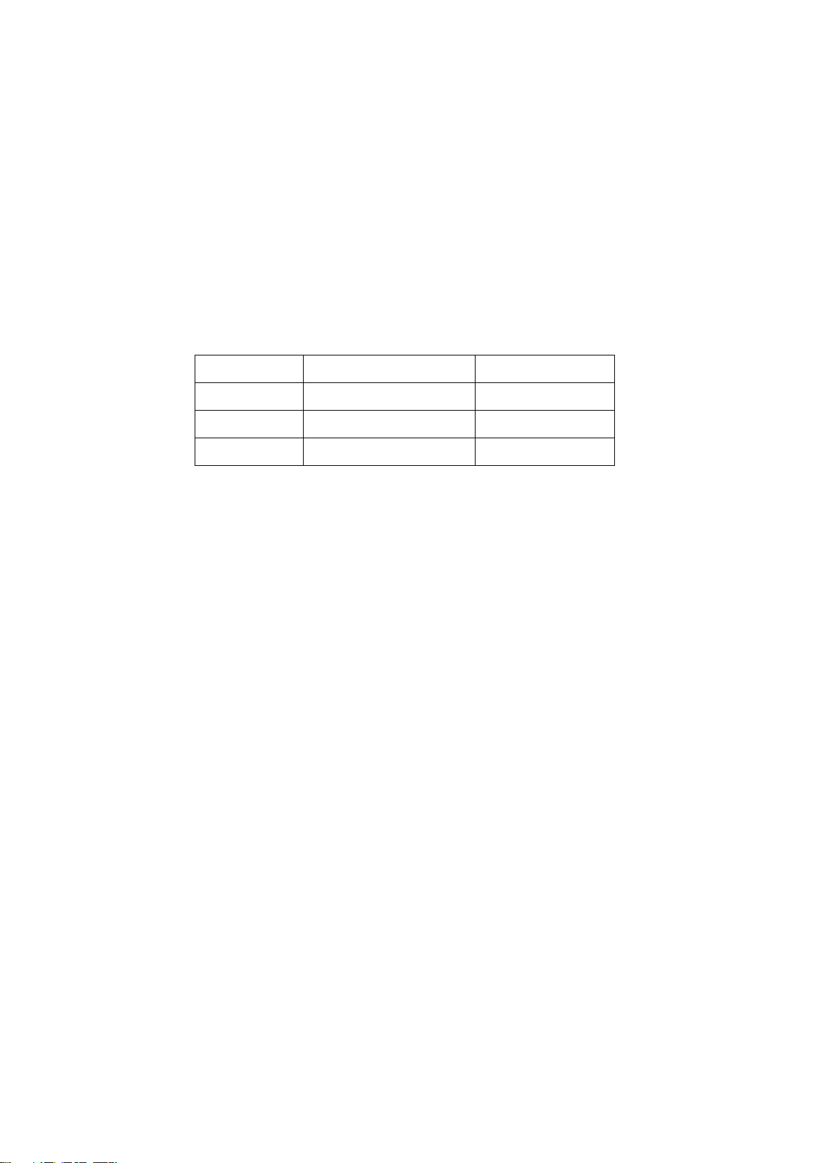
2.12 For the storage make sure to put it in a place where the environment can be controlled so as to
prevent the temperature and humidity from exceeding the limits as specified in the manual. For
prolonged storage, it is necessary to house it in an anti-moisture bag and put them altogether in one
place. The ambient conditions are tabulated as follows:
Temperature Scope for operation 0 ~ +50 oC
Scope for storage -20 ~ +60 oC
Humidity Scope for operation 20% ~ 85%
Scope for storage 10% ~ 90%
2.13 Display of a fixed picture for a long time may result in appearance of picture residue on the
screen, as commonly called “ghost shadow”. The extent of the residual picture varies with the
maker of LCD screen. This phenomenon doesn’t represent failure. This “ghost shadow” may remain
in the picture for a period of time (several minutes). But when operating it please avoid displaying
still picture in high brightness for a long time.
3. Points for attention during installation
3.1 The front panel of LCD screen is of glass. When installing it please make sure to put it in place.
3.2 For service or installation it’s necessary to use specified screw lest it should damage the screen.
3.3 Be sure to take anti dust measures. Any foreign substance that happens to fall down between
the screen and the glass will affect the receiving and viewing effect
3.4 When dismantling or mounting the protective partition plate that is used for anti vibration and
insulation please take care to keep it in intactness so as to avoid hidden trouble.
3.5 Be sure to protect the cabinet from damage or scratch during service, dismantling or mounting.
2
Page 5
Alignment instructions
1. Test equipment
PM5518 (video signal generator)
VG-849 (VGA and HDMI signal generator)
CA210 (color analyzer)
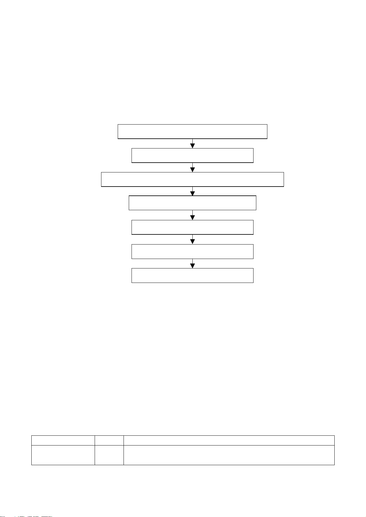
2 Alignment flow-chart
The alignment flow-chart is shown as fig-1
Check DDC, HDCP KEY, FLASH and POWER control IC
Factory initialization setup
IF channel AFT voltage of TV and AGC voltage adjustment
ADC correction of VGA and YPbPr
White balance adjustment
Fig-1 adjustment flow-chart
3 Unit adjustments
Connect all the boards according to wiring diagram, connect with power and observe the display.
Method for entering factory menu: press “INPUT”, “2”, “5”, ”8” and “0” in turn to enter factory
menu; press “CH+” and “CH-” to select adjustment items and press “VOL+” and “VOL-” to adjust
value items, press “MENU” repeatedly to exit.
Method for software upgrading: When software upgrading please enter factory menu first, enter
ISP item of OPTION, set ISP to 1 and you can begin to upgrade. After upgrade finished, it needs to
set ISP back to 0. If the picture can’t display when upgrading, it needs to solder JB1 on the main
board. Please unsolder JB1 again after upgrading.
3.1 Initialization
Enter factory menu, select “OPTION”, “EEPROM” and “HOTEL OPTION” sub-menu, adjustment of
items to see table1.
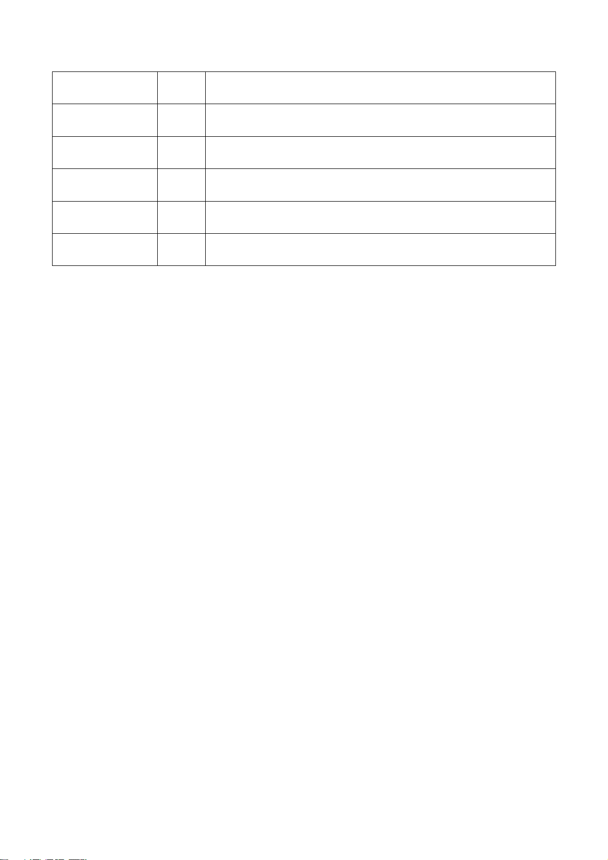
Table1 sub-menu adjustment
Items Preset Introduce
HOTEL 0 ON: HOTEL OPTION of factory menu is optional
OFF: HOTEL OPTION of factory menu is not optional
Performance check
Preset ex-factory
3
Page 6
LOGO 1 ON: display LOGO in no signal or turn on
OFF: no LOGO display
ADC PRESCALE 02E Software will preset the data according the unit and the data can be adjusted when
needed.
SIF PRESCALE 02E Software will preset the data according the unit and the data can be adjusted when
needed.
BACK LIGHT FF Software will preset the data according the panel and the data can be adjusted
when needed.
ALL COLOR 1 1: white balance of each channel auto offset based on the HDMI white balance
0: white balance of each channel adjust the offset base separately
EEPROM-MEMORAY
RECALL
> EEPROM Initialization (operate when EEPROM data chaos)
3.2 Adjustment for AFT voltage and AGC voltage of IF channel in TV
3.2.1 IF AFT adjustment
Enter the factory menu and set IF VCO to 1, or press “INPUT”, “2”, “5”,”8”, “1” to enter VCO
adjust mode, adjust L109 to value 2.5V of TP105 (B face), then set IF VCO to 0.
3.2.2 IF AGC adjustment
Input 60DB RF signal (184.25MHz for Chinese, 175.25MHz for America) to RF terminal,
adjust RP101 to value 3V of TP102 (B face) and there should be no obvious snowy picture.
Increase the signal to 90dBV and it should be display normally and no obvious noise.
3.3 White balance adjustment
3.3.1 white balance adjustment of HDMI
a. Input VG-848 signal from HDMI: TIMING854(800* 600/60Hz) and eighth level gray-scale
signal of PAT920. Use color analyzer CA210 to adjust white balance.
b. Enter submenu of COLOR TEMP. Select 9300k of color temperature
c. Fixed value of B OFF, adjust R OFF and G OFF, let the color coordinate of the second level
be 285,293 and the brightness be about 3nit- 6nit. Fixed value of B GAIN, adjust R GAIN and G
GAIN, let the color coordinate of seventh level be 285,293. Adjustment R OFF, G OFF, R GAIN and
G GAIN repeatedly until the value of the two levels gray-scale be 285, 293.
3.3.2 VGA/YPBPR/AV white balance check and correction
a. Input VG-848 signal of VGA: TIMING854(800* 600/60Hz) (PATIERN:CROSS) and auto
adjust to full screen, then input PAT948 black/white signal, enter factory menu ADC ADJ, select
AUTOTUNE and wait for OK display. Input PAT920(8 gray levels), check if the white balance is
normal, if not, enter COLOR TEMP menu, set ALL COLOR to 0 and fine adjust according the
method of 3.3.1 c)
b. connect VG-848 signal of YPBPR to YPBPR terminal and input TIMING972(1080i/60HZ)
100% color bar of PAT976(include black/white bar), Enter submenu of ADC ADJ, Select
AUTOTUNE and wait for OK display. Input PAT920(8 gray levels), check if the white balance is
normal, if not, set ALL COLOR to 0 and fine adjust according the method of 3.3.1 c)
c. Input AV signal(PM5518, 8 gray levels, PAL for Chinese and NTSC for America) to VIDEO 1
terminal, check if the white balance is normal, if not, set ALL COLOR to 0 and fine adjust according
the method of 3.3.1 c)
Note: it can’t set back to 1 once ALL COLOR changes to 0.
4
Page 7
4 Performance check
4.1 TV function
Enter searching menu → auto search, connect RF-TV terminal with central signal source and check
if the picture is normal, if there are channels be skipped. Check CCD and V-CHIP function (for
America).
4.2 AV/S, YPbPr terminals
Input AV/S, YPbPr/YCbCr HD signal, check if it is normal.
4.3 VGA terminal
Insert VGA terminal, input VGA format signal of 640X480@60 Hz and check if the display is normal.
4.4 HDMI terminal
Insert HDMI terminal, input signal of 640 X 480@60 Hz signal and check if the display is normal and
the HDCP is normal.
4.5 check sound channel
Check the speaker and headphone of each channel.
4.6 other function check
Check the turn on/turn off timer, asleep timer, picture/sound mode, OSD, freeze/mute,
stereo/SAP(for America), magic picture, etc.
4.7 presetting before ex-factory
Item Setting Item Setting Item Setting
PICTURE MODE NAUTRAL
AUDIO MODE DK
SOUND MODE NEWS HALFTONE 50
NR WEAK DURATION 15 ANTENNA CATV
ZOOM FULL
OSD language
English /
Chinese
VGA/HDMI
color temperature
STANDARD
5
Page 8

Method of software upgrading
1. The tools and software demanded
1) Please confirm that PC has the software of ISP_TOOL and install the parallel interface drive
program Port95nt.
2) ISP_TOOL icon is bellow:
3) One parallel cable (25 pins) and one VGA cable (15 pins), the parallel cable connects the PC and
the upgrade instrument, the VGA cable connects the TV and the upgrade instrument.
2. The steps for upgrading software
1) Please confirm that the connection wires and the upgrade instrument are connected well before
the software written and then power on the TV.
2) Double click the icon ISP_TOOL to open it:
3) Press “Connect“ to connect TV, if the connection is done successfully as shown below, then
press “enter”.
6
Page 9

Note: if it appears error, check the connection wires and check if ISP item of the factory menu is set
to 1, if not, please set it to 1.
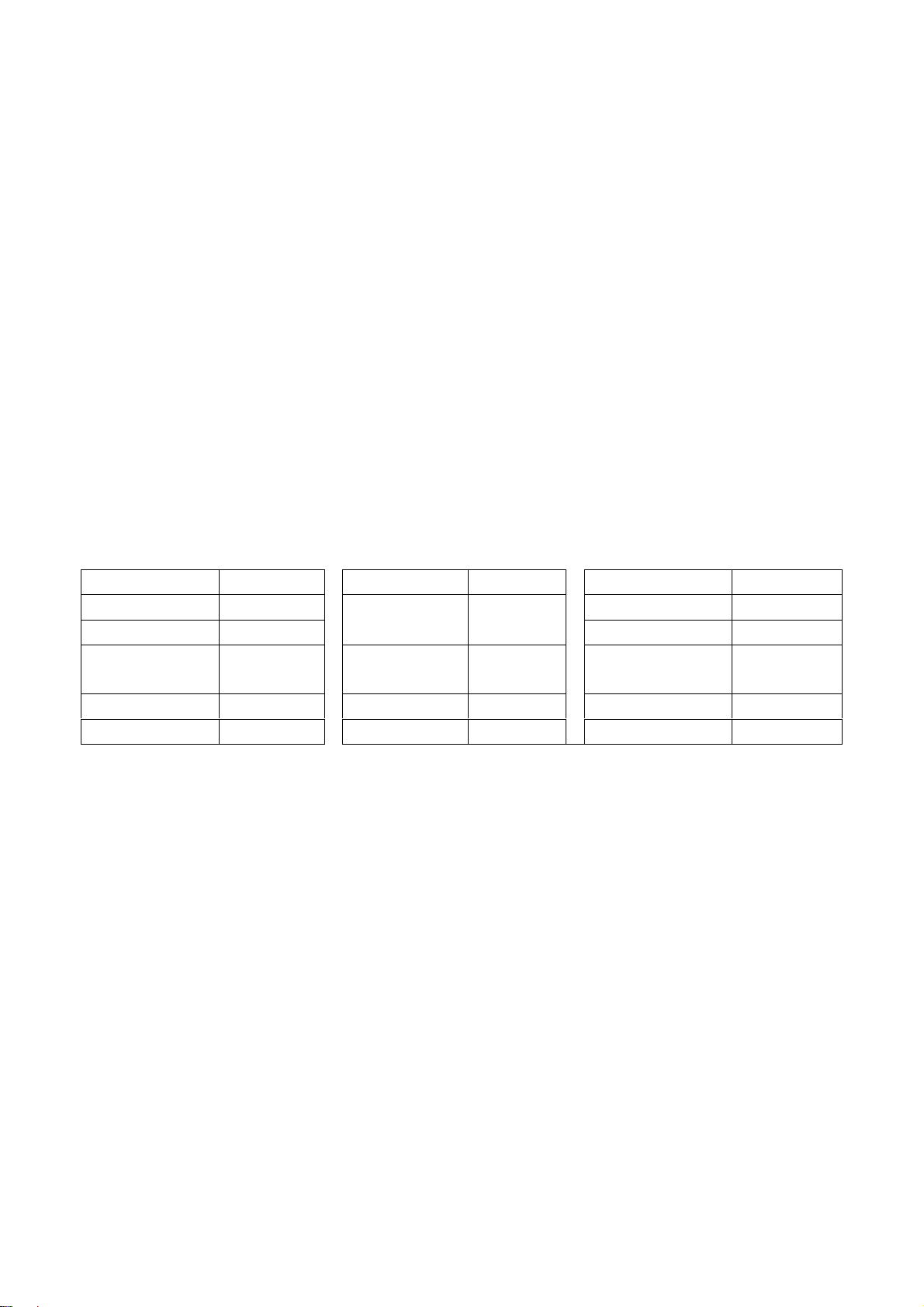
4) After connection is done, it needs to read the Binary document. Press “Read” as shown below:
5) Search the document needed to write in the “Read” check box.
7
Page 10

Select
6) Select the document then the window will appear as shown below:
8
Page 11
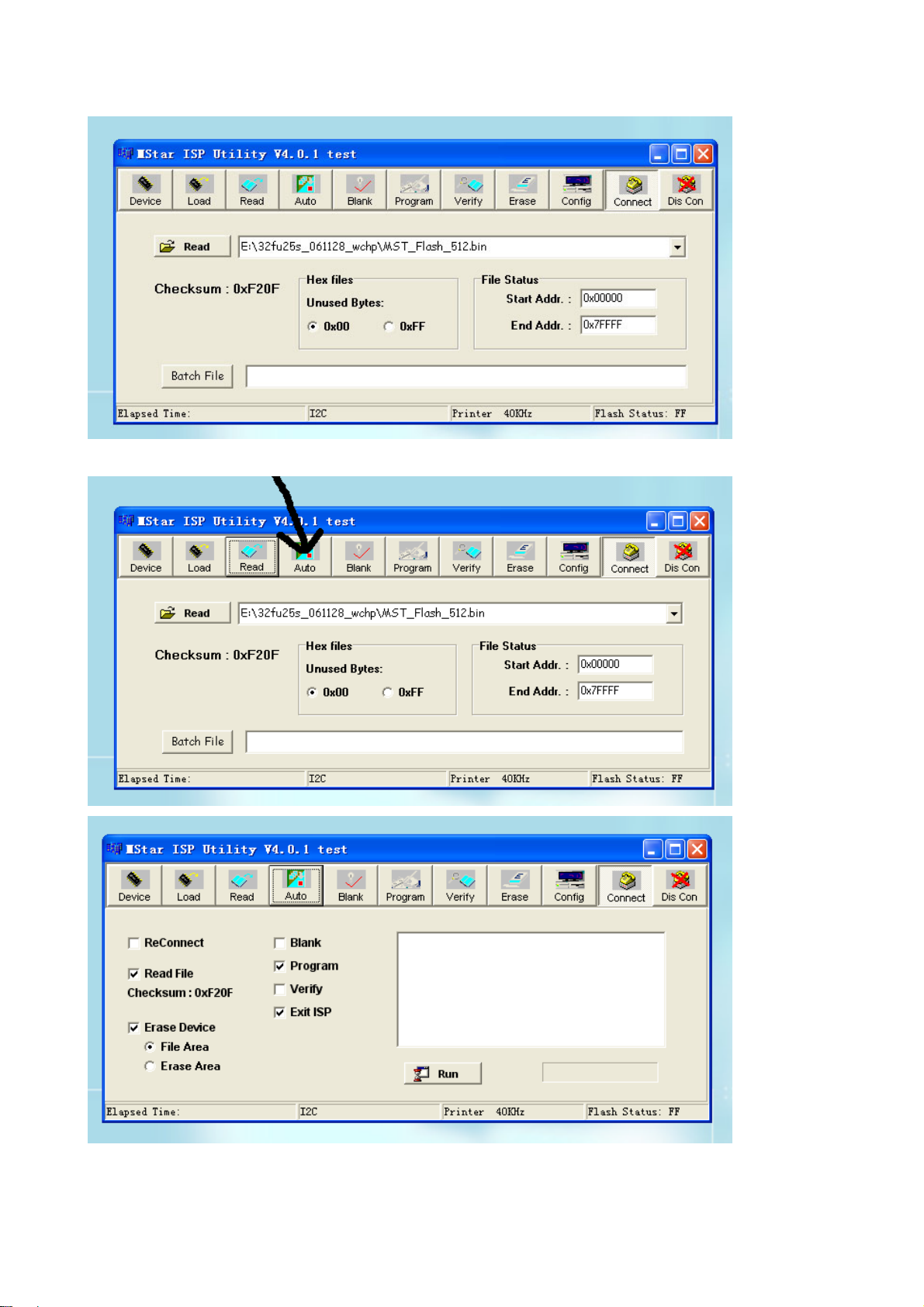
7) Press “Auto” to select the writing function.
Select the items shown in the picture above:
(a) Read File
9
Page 12

(b) Program
(c) Exit ISP
(d) Erase Device
(e) File Area
8) Press “Run” to begin the writing program, wait till the blue bar is complete.
After writing, it will display OK:
If there is error appeared (shown as below), press “Run” again to rewrite the program till it is
success.
10
Page 13

Note1: keep the connection well and don’t cut off the power during the writing process.
Note2: the writing speed can be adjusted as shown below. Select “Config” then adjust Speed BAR,
the value is bigger the speed is faster. But it is easier to appear error when increase the speed, so it
need to select a suitable speed according the PC.
Step 1
Step 2
11
Page 14

Working principle analysis of the unit
The RF signal received by antenna will be sent to tuner TUNER101, then IF signal will be
obtained through high amplifier and mixed frequency, through pre-intermediate amplified by V101,
then it will be sent to acoustic surface-wave Z102 to do IF filter and get better IF characteristics,
then it will be sent to N101 (R2S10401) to do intermediate amplification, phase-locked loop VCO
and synchronous wave detection to get composite video signal TV-VIDEO; after pre-intermediate
amplification IF will also be sent to acoustic surface-wave Z101 to do filter at the same time, then it
will be sent to N101 to do intermediate amplification and output the second sound intermediate
frequency signal (TV-SIF).
The TV-VIDEO signal output from R2S10401 together with TV-SIF will be sent to main IC NS2
(MST9U19A). Video signals of AV1, AV2, S-VIDEO and YPbPr will be sent to MST9U19A, and
their audio signals will also be sent to MST9U19A (AV1 and YPbPr share one group of audio ports,
AV2 and S-VIDEO share one group of audio ports). The video and audio signals of VGA and HDMI
will be sent to MST9U19A, too.
The main IC NS2(MST9U19A) is a high performance and fully integrated IC, which can realize
HDMI processing, video demodulating, video switch selection, A/D and D/A conversion,
interlace/de-interlace processing, modes conversion, OSD and low-voltage differential output, ect.
And it also has functions of audio selection, processing and MCU.
The video signal via MST9U19A processing, output 4 pairs differential signal and 1 pair clock
signal for PDP panel display. AV1, AV2, S-VIDEO and video signal of TV via selecting and
processing, then output AV-OUT signal to double amplifying, then it will be sent to AV-OUT.
Audio signal via MST9U19A processing, one way will be sent to sound amplifier NV4
(R2S15102) amplifying to speaker. The other way via NV3(LM358) amplifying, then sent to AV-OUT.
12
Page 15

Block diagram
HDMI
VGA
YPbPr
AV1-V
AV2-V
S-Y
S-C
VGA-L/R
AV1/YPbPr-L/R
AV2-L/R
TUNER
TV-V
TV-SIF L/R-AV OUT
CVBS
V-AV OUT
EDID
24C02
SAW
IF AMP
R2S10401
EDID
24C02
LCD TV
CONTROLLER
MST9U19A
POWER MEG.
ATMEG8L
FLASH
EEPROM
HDCP KEY
PANEL
AUDIO AMP .
R2S15102
SPEAKER
AMP
LM358
2*AMP
13
Page 16

IC block diagram
MST9U19A:
4, 5, 7, 8, 10, 11, 1, 2: HDMI input
16, 17: H/V synchronizing input
27, 25, 22: RGB input
30, 32, 35: YPbPr input
42, 43: S-VIDEO input
46: AV1-V input
47: AV2-V input
49: TV-VIDEO input
51: CVBS output
63, 64: VGA-L/R input
66, 67: AV1/ YPbPr-L/R input
68, 69: AV2/S-L/R input
135: search station synchronizing check input
154: HDMI hot-plug check output
145: standby control output
148: picture on/off output
149: mute control output
72, 73: L/R output (AV-OUT)
74, 75: L/R output (amplifier)
162-271: 4 pairs differential signal and 1 pair
clock signal output
131: SDA
132: SCL
14
Page 17

R2S10401:
15
Page 18

1, 2: VIF input
23: SIF input
7: TV-CVBS output
10: TV-SIF output
17: SDA
18: SCL
R2S15102NP:
5, 11: L/R input
1, 15: L/R output
13: mute control input
16
Page 19

Wiring diagram
power board
backlight
pins
key board
panel
pins
pins
pins
pins
pins
pins
pins
pins
main board
17
Page 20

Trouble shooting
k
f
p
d
1. No raster
Turn on power supply, chec
if the red indicator is light in
the STANDBY?
Check if PIN3 (5V) of XB20
on the main board is normal?
Check STANDBY circuit o
ower supply board
no
no
no
Replace NS2
yes
Press POWER button in the
unit or sensor control an
check the indicator.
blue
Check if the PIN3 of XS14 on
the main board is high-level?
yes
Check the
backlight board
Replace
NS14
red
no
Check if XS15 pin 11 on main
board is high-level?
yes
Check power
supply board
18
Page 21

2. Raster, but no picture
y
p
d
f
N
t
f
t
p
Check if the unit button
and remote control
operation?
yes
no
no
Replace
main board
no
Enter factory-menu,
initialization EEPROM,
then turn off the TV,
turn on again, displa
icture?
Does display OSD
menu in screen when
ress menu button?
yes
Adjust main boar
again
Replace TUNER
yes
yes
yes
Check if there is no
signal in all channels?
no
Which is no signal
of channels?
TV
Check if 2VPP signal
and noise wave o
101(PIN7) on the
main board?
no
Check if outpu
no
IF signal o
TUNER (pin11)
is normal?
yes
Check IF circui
(N101)
HDMI/VGA/YPRPB
Replace
main board
19
Page 22

3.no sound
d
f
N
N
Check if PIN2, 3,13 an
14 voltage of NV4 is
normal?
Check power supply
no
yes
Check PIN5 and
PIN11 output wave o
V4
no
Check PIN10 wave of
101
no
Check PIN11 wave of
TUNER
no
Replace TUNER
yes
yes
yes
Replace NV4
Replace NS2
Replace N101
20
Page 23

main board
Page 24

main board
Page 25

main board
Page 26

main board
Page 27

main board
Page 28

power
Page 29

backlight
Page 30

APPENDIX-A: Main assembly LCD-22XR7SN
NAME NO.
Main board
Key board
Backlight board
Power board
Remote control
Panel
XI6HU080110
XI6HU0060510
XI6HA0061410
XI6HU0082010
XI6010Y05601
XI5203227203
MAIN COMPONENT AND IT'S NO.
N101
NS2
NV4
RC-Y56-0A
CLAA220WA01 032
R2S10401 (5271040101)
MST9U19B (5270919002)
R2S15102NP (5271510201)
Page 31

LCD-22XR7SN
Page 32

PART LIST OF EXPLODED VIEW
NO. DESCRIPTION
1 Front cabinet
2 Key board
3
4
5 Main board
6
7
8
9
10
11
Speaker
Panel
Back cabinet
Stand
Power board
Back light board
User manual
Remote control
Page 33

PART LIST
LCD-22XR7SN ver.1.0
REF.No. PARTS No. DESCRIPION Q'TY REMARK
1 XI5QK26U105B Front cabinet 1
2
3
4
5
6
7
8
9
10 XI5944034300
11
Only the parts in above list are used for repairing.
Other parts except the above parts can't be supplied.
XI6HU0060510
XI6HU080110
XI5HK37WH02A
XI6151087130
XI6HU0082010
XI6HA0061410
XI6010Y05601
Key board 1
Speaker
Panel
Main board 1
Back cabinet
Stand
Power board
Back light board
User manual
Remote control
1
1 CPT CLAA220WA01 032
1
1
1
1
1
1
Page 34

WALL MOUNTING INSTRUCTIONS
Safety Precautions:
1. Be sure to ask an authorized service personnel to carry out setup.
2. Thoroughly read this instruction before setup and follow the steps below precisely.
3.The wall to be mounted should be made from solid materials. Only use accessories supplied by the manufacturer.
4.Very carefully handle the unit during setup. We are not liable for any damage or injury caused by mishandling or improper installation.
5.Be sure to place the unit on a stable and soft platform which is strong enough to support the unit.
6.Do not uplift the speaker when moving the display. The appearance of the unit may different from the actual ones.
7.Design and specifications are subject to change without notice.
8. Retain these instructions for future reference.
Note: All the wall mounting parts are optional and may be unavailable in your model.
Below we will show you how to mount the Display on the wall using our company’s wall mounting components.
11
Take out these parts from the box.
Wall Mounting
Component
(including bracket
and connector)
Expansion Bolt
Wood Screw
M4 Screw
Fig. 1
Fully insert the two insertions on the wall mounting connector into the
44
locating grooves on the wall mounting bracket from top to bottom end.
22
Screw 4pcs expansion bolts to fix
the wall mounting bracket on the
wall.
Wall
Wall Mounting Bracket
Fig. 2a
If your wall is a wooden structure, please
fix the wall mounting bracket on the wall
with 8 pcs wood screws.
Wall
Wall Mounting Bracket
Fig. 2b
55
Use screwdriver to revolve the Clasper to the Positioner
following the direction of the arrow.
33
Use the 4pcs M4 screws to fix the wall
mounting connector to the rear of the
display unit.
Wall Mounting Connector
Fig. 3
Clasper
Positioner
Fig. 4
Fig. 5
Page 35

Page 36

Nov/2008
 Loading...