

Page 1
FILE NO
SERVICE MANUAL
LCD TV
LCD-19E30
PRODUCT CODE No.: 1 682 347 60
CHASSIS NO. : SSA19CT-00
LCD-
PRODUCT CODE No.: 1 682 347 61
CHASSIS NO. : SSA26CT-00
26E30
LCD-32E30
PRODUCT CODE No.: 1 682 347 62
CHASSIS NO. : SSA32CT-00
LCD-
PRODUCT CODE No.: 1 682 347 63
CHASSIS NO. : SSA42CG-10
LCD-
PRODUCT CODE No.: 1 682 347 64
CHASSIS NO. : SSA42CG-00
42E30
42E30F
REFERENCE No.:SM0945001-01
Page 2

CONTENTS
1. Safety precautions .................................................................................................
2. Alignment instructions and method of software upgrading.....................................
3. Working principle analysis of the unit ...................................................................
4. Block diagram ......................................................................................................
5. IC block diagram..................................................................................................
6. Wiring diagram ...................................................................................................
7. Troubleshooting guide..........................................................................................
8. Schematic diagram ..............................................................................................
APPENDIX-A: Assembly list
APPENDIX-B: Exploded View
Removing or Installing the Stand
Wall mounting instructions
1
5
17
18
21
24
27
31
Page 3

Attention:
please read the following points carefully.
This service manual is only for service personnel to take reference with. Before
servicing
Safety precautions
1. Instructions
Be sure to switch off the power supply before replacing or welding any components or
inserting/plugging in connection wire Anti static measures to be taken (throughout the entire production
process!):
a) Do not touch here and there by hand at will;
b) Be sure to use anti static electric iron;
c) It’s a must for the welder to wear anti static gloves.
Please refer to the detailed list before replacing components that have special safety requirements.
Do not change the specs and type at will.
2. Points for attention in servicing of LCD
2.1 Screens are different from one model to another and therefore not interchangeable. Be sure to
Use the screen of the original model for replacement.
2.2 The operation voltage of LCD screen is
protecting yourself and the machine when testing the system in the course of normal operation or
right after the power is switched off. Please do not touch the circuit or the metal part of the module
That is in operation mode. Relevant operation is possible only one minute after the power is switched
off.
2.3 Do not use any adapter that is not identical with the TV set. Otherwise it will cause fire or damage
to the set.
2.4 Never operate the set or do any installation work in bad environment such as wet bathroom,
laundry, kitchen, or nearby fire source, heating equipment and devices or exposure to sunlight etc.
Otherwise bad effect will result.
2.5 If any foreign substance such as water, liquid, metal slices or other matters happens to fall into the
module, be sure to cut the power off immediately and do not move anything on the module lest it should
cause fire or electric shock due to contact with the high voltage or short circuit.
2.6 Should there be smoke, abnormal smell or sound from the module, please shut the power off at
once. Likewise, if the screen is not working after the power is on or in the course of operation, the
power must be cut off immediately and no more operation is allowed under the same condition.
2.7 Do not pull out or plug in the connection wire when the module is in operation or just after the
power is off because in this case relatively high voltage still remains in the capacitor of the driving
circuit. Please wait at least one minute before the pulling out or plugging in the connection wire.
2.8 When operating or installing LCD please don’t subject the LCD components to bending, twisting or
extrusion, collision lest mishap should result.
high voltage
. Be sure to take proper measures in
2.9 As most of the circuitry in LCD TV set is composed of CMOS integrated circuits, it’s necessary to
pay attention to anti statics. Before servicing LCD TV make sure to take anti static measure and
ensure full grounding for all the parts that have to be grounded.
2.10 There are lots of connection wires between parts behind the LCD screen. When servicing or
moving the set please take care not to touch or scratch them. Once they are damaged the screen
would be unable to work and no way to get it repaired.
If the connection wires, connections or components fixed by the thermo tropic glue need to disengage
when service, please soak the thermo tropic glue into the alcohol and then pull them out in case of
damage.
3
Page 4

2.11 Special care must be taken in transporting or handling it. Exquisite shock vibration may lead to
breakage of screen glass or damage to driving circuit. Therefore it must be packed in a strong case
before the transportation or handling.
2.12 For the storage make sure to put it in a place where the environment can be controlled so as to
prevent the temperature and humidity from exceeding the limits as specified in the manual. For
prolonged storage, it is necessary to house it in an anti-moisture bag and put them altogether in one
place. The ambient conditions are tabulated as follows:
Temperature Scope for operation
Scope for storage
Humidity Scope for operation 0% ~
Scope for storage 0% ~ 90%
2.13 Display of a fixed picture for a long time may result in appearance of picture residue on the
screen, as commonly called “ghost shadow”. The extent of the residual picture varies with the maker
of LCD screen. This phenomenon doesn’t represent failure. This “ghost shadow” may remain
in the picture for a period of time (several minutes). But when operating it please avoid displaying still
picture in high brightness for a long time.
5
~+ 35oC
0~
+ 40oC
90
%
3. Points for attention during installation
3.1 The front panel of LCD screen is of glass. When installing it please make sure to put it in place.
3.2 For service or installation it’s necessary to use specified screw lest it should damage the screen.
3.3 Be sure to take anti dust measures. Any foreign substance that happens to fall down between the
screen and the glass will affect the receiving and viewing effect
3.4 When dismantling or mounting the protective partition plate that is used for anti vibration and
insulation please take care to keep it in intactness so as to avoid hidden trouble.
3.5 Be sure to protect the cabinet from damage or scratch during service, dismantling or mounting.
4
Page 5
Alignment instructions
1. Test equipment
VG-848 (YPbPr,VGA signal generator)
VG-849 (HDMI signal generator)
FLUKE 54200(TV signal generator)
CA210
2. Power test
Connect main board, power board and IR board according the wiring diagram, connect
the power and press power key(Remote controller or Keypad) button to turn on the TV.
a) Test the pin voltage of P802/power board , the data is shown in table1:
P802 Pin1,2 Pin3,4 Pin5,6,7 Pin8,9 Pin10,11,12 Pin13 Pin14 Pin15 Pin16
Voltage GND 22.8-25.2V GND 11.4-12.6V 4.75-5.25V
P802 Pin1,2 Pin3,4 Pin5,6,7 Pin8,9 Pin10,11,12 Pin13 Pin14 Pin15 Pin16
Voltage GND 11.4-12.6V GND 11.4-12.6V 4.75-5.25V
(white balancer)
Table1 voltage data of P802
For42”/32”/26”
On:2V-5.5V
Off: 0-0.5V
For 19”
On:2V-5.5V
Off: 0-0.5V
<0.6V 2-5V 2.5-5V PWM
<0.6V 2.5-5V 2.5-5V PWM
b) Test the pin voltage of P803/power board, the data is shown in table2:
Table2 voltage data of P803
For42”/32”/26 only
P803 Pin1,2,3,4,5 Pin6,7,8,9,10 Pin11 Pin12 Pin13 Pin14
Voltage 22.8-25.2V GND NC 2.5V-5V 2.5-5V PWM NC
5
Page 6
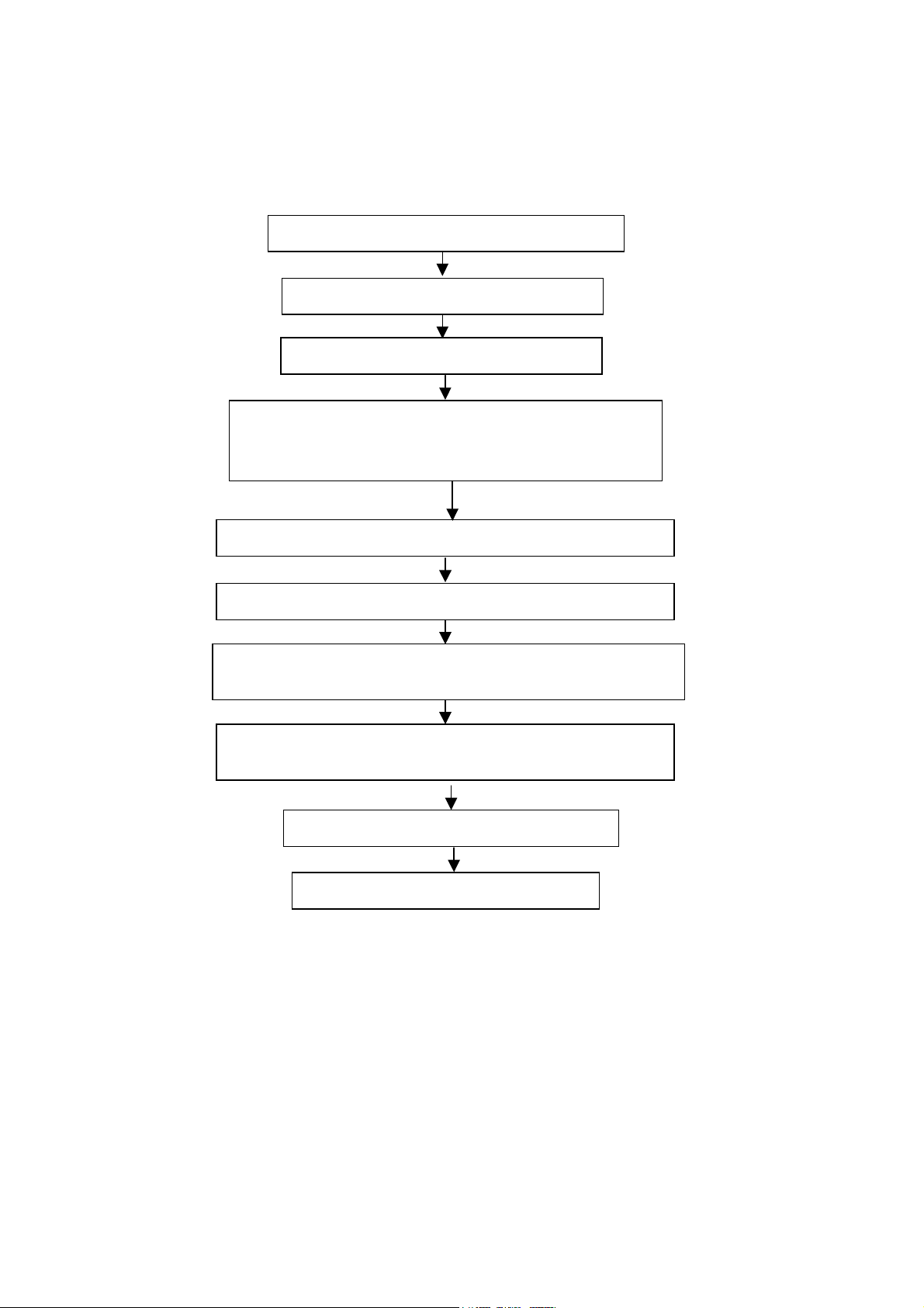
3. Alignment flow-chart
The alignment flow-chart is shown as fig-1
Check if DDC, HDCP KEY, FLASH are written
Combined test for general assembly
White balance adjustment
Connect to the center signal source and check each
Function of TV (station leaking, analog control, etc.)
Check the output of earphone and speaker.
Input AV/SVIDEO signal and check the function
Input HD signal and check the function of YPbPr
Input VGA signal and check if the display is normal, check
the function (analog control), horizontal/vertical center, etc.
Input HDMI signal and check if the display is normal, check
the function (analog control), horizontal/vertical center, etc.
Preset ex-factory
Check the accessories and packing
Fig-1 adjustment flow-chart
6
Page 7
4. Adjustment instruction
A
A
At any input source then press the “Mute” (remote control) and “Menu (key pad) to enter factory mode.
During Factory menu, if “MENU” or “EXIT” key is pushed, system will exit factory mode.
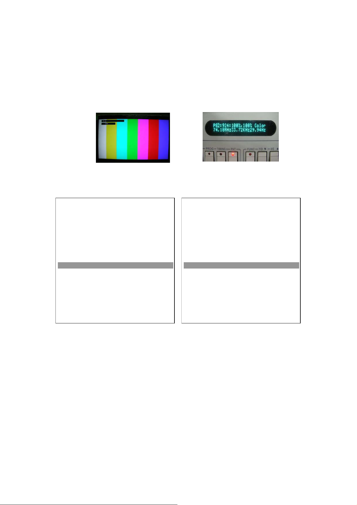
4-1. Source Calibration
4-1.1. Set the signal generator to TV input sources Video3; ASTRO-859 signal setting to1080i
(PG2 mode Timing 933 and Pattern 924 100% Color Bar.)
4-1.2. Entering into factory Mode: Press up or down key of remote control to select “Auto Calibration”, Press
䇸OK䇹 key to enter the item.
FACTORY MENU
Cool
Warm
Normal
Shipping
NV Clear
Full Power
uto Calibration
RF Burn In
Service Mode
Reset
OK
OK
OK
< Factory >
OK
OK
>
< Off >
< Off >
OK
Board Name: L19112_Rev.1
VERSION: SSA19C-WXGA V1.0
04/10/09 00:00:00
Cool
Warm
Normal
Shipping
NV Clear
Full Power
uto Calibration
RF Burn In
Service Mode
Reset
Board Name: L19112_Rev.1
VERSION: SSA19C-WXGA V1.0
04/10/09 00:00:00
FACTORY MENU
-> Source calibration performed automatically when finished that will show OK.
OK
OK
OK
< Factory >
OK
OK
OK
< Off >
< Off >
OK
7
Page 8
Repeat step 2 to do VGA input sources,
ASTRO-859 signal setting to1024X768 60Hz (PG1 mode: Timing 856 and Pattern 914:5 White Block.)
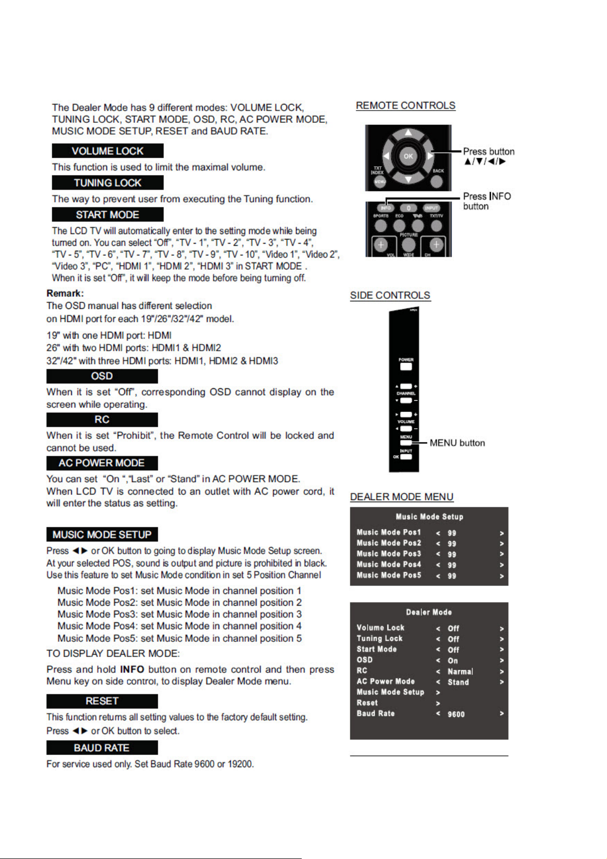
Repeat step 2 to do TV input sources of Video1 (Composite-AV):
Fluke 54200 TV SIGNAL GENERATOR: Signal setting to PAL System and Pattern: CHECKER.
4-2. Color Temperature Adjustment & Check
4-2.1. Set the signal generator to RGB, 1024*768, 60HZ (ASTRO-859: PG1 856), Level: 0.56V (80%).
Full white pattern.
4-2.2. Press up or down key of remote control to select “Cool”, Press 䇸OK䇹 key to enter the item.
R, G, B drive values are set for COOL, Medium, and WARM independently.
4-2.3. Select 䇸Cool䇹
Cool spec.:26”/32”/42”
x= 0.267±0.010
y= 0.271±0.010
Cool spec.:19”
x=0.281±0.010
y=0.288±0.010
If the x and y value are larger than specification,
Decrease Green drive from default value.
Increase Blue drive from default value.
If the x or y or both x and y value is/are smaller than specification.
Decrease Blue drive from default value
According to a x and y value, please following adjustment of 1 or 2.
1 If x value is higher than spec
Increase Green drive from default value.
Increase Blue drive from default value.
2 If y value is higher than spec,
Decrease Green drive from default value
8
Page 9

4-2.4. Select [Normal]
A
Normal spec.: 26”/32”/42”
x=0.281±0.010
y=0.288±0.010
Normal spec.: 19”
x=0.300±0.010
y=0.310±0.010
Adjust G drive (GREEN) or B drive (BLUE) to set x and y above.
4-2.5. Select [Warm]
WARM spec.: 26”/32”/42”
x=0.301±0.010
y=0.310±0.010
WARM spec.: 19”
x=0.314±0.010
y=0.323±0.010
Adjust G drive (GREEN) or B drive (BLUE) to set x and y above.
4-2.6 Exit Factory Mode:
After finish adjusting color temperature, press [MENU] to exit factory mode.
5. Items of Factory menu
Vendor may customize design and add adjustment items Factory menu as far as all required items are
included.
Press up and down key can move high light item from Cool ->Warm -> Normal ->Shipping-> NV clear-> Full
Power -> Auto Calibration -> RF Burn In -> Reset.
The NV Clear and Reset to Default items will have a check dialog “yes or no” to do or not.
Push “Enter” key can select high light item function. (Press left and right can adjust value)
Display model name, firmware version and released date on bottom
FACTORY MENU
Cool
Warm
Normal
Shipping
NV Clear
Full Power
uto Calibration
RF Burn In
Service Mode
Reset
OK
OK
OK
< Factory >
OK
OK
>
< Off >
< Off >
OK
Board Name: L19112_Rev.1
VERSION: SSA19C-WXGA V1.0
04/10/09 00:00:00
9
Page 10

5-1) Cool
Press up or down key can select high light item function.
Press enter key to enter the item.
Following data for color temp shall be edited manually.
-R, G, B data for each preset.
-Press “Up” or “Down” key to select “R”, “G”, “B” item
-Press “Left” or “Right” key to set the “R”, “G”, “B” value.
-Press “MENU” or “EXIT” item to exit to factory mode
5-2) Warm
Press up or down key can select high light item function.
Press enter key to enter the item.
Following data for color temp shall be edited manually.
-R, G, B data for each preset.
-Press “Up” or “Down” key to select “R”, “G”, “B” item
-Press “Left” or “Right” key to set the “R”, “G”, “B” value.
-Press “MENU” or “EXIT” item to exit to factory mode
5-3) Normal
Press up or down key can select high light item function.
Press enter key to enter the item.
Following data for color temp shall be edited manually.
-R, G, B data for each preset.
-Press “Up” or “Down” key to select “R”, “G”, “B” item
-Press “Left” or “Right” key to set the “R”, “G”, “B” value.
-Press “MENU” or “EXIT” item to exit to factory mode
5-4) Shipping
Press up or down key can select high light item function.
Press “Left” & “Right” key to select the item. Default set in Factory mode.
Following shipping area to select the item (Factory/Asia/China/S America).
5-5) NV CLEAR
Initialize program’s default values to NVRAM for following adjustment items accuracy.
In factory mode it is the first and important step to make sure all values are default value and correct.
- Reset settings: Gamma table, Channel table (Favorite channel, Channel label etc.), Model table
(H/V Position, Clock, Phase), Source dependent setting (Contrast, Brightness etc.), Common
setting (Volume, Language etc.), Parental Control (Rating, Password etc), Closed Caption.
To avoid a mistake initial process after factory setting is done. This item will have a check dialog “yes or no”
to do the initial or not.
NOTICE:
This item just enabled in PC input and after this item is processed then the DUT needs to be powered off
then AC powered off.
5-6) Full power
This is for power consumption testing.
To measure the maximum power consumption of TV set, we adjust the value of following items to maximum.
- Video: Contrast maximum value, Brightness maximum value, Backlight maximum value.
- Audio: Volume maximum value, Bass default value, Treble default value.
Press enter key to turn on Full Power and OSD stay display until press enter key to recover from Full Power.
10
Page 11

5-7) Auto Calibration
Auto Calibration (gain/offset) must be adjusted color by firmware automatic adjustment in PC, Video1
(Composite) and Video3 input source.
This item will have a result dialog “OK” or “NG”.
5-8) RF Burn In
Use “snow” pattern for burn in. Selected items are “On” and “Off”.
While turn on burn in mode, firmware will automatically turn off “Auto power off” function.
If there is no power supply suddenly, firmware will re-enter burn in mode automatically
when power supply is back.
Pressed the “Power” key, firmware will automatically turn off burn in mode.
- Burn in mode: Source is “ANT”, Input Configuration is “Antenna” and channel is NTSC channel 2.
5-9) Service Mode
Press “Left” & “Right” key to select the item. Default set in “On”.
When use the RS-232 serial port to control LCD TV set to “On”.
When use the F/W update function set to “Off”.
5-10) Reset
Reset all settings of OSD menu to default value.
- Reset settings: Channel table, Model table (H/V Position, Clock, Phase), Source dependent setting
(Contrast, Brightness etc.), Common setting (Volume, Language etc.)
11
Page 12
6. Dealer Mode Function
12
Page 13

7. Performance check
7-1 TV function
Connect RF to the center signal source, enter Channel menu ĺ auto tuning, check if there are channels be
skipped, check if the picture and speaker are normal.
7-2 AV/S-Video terminals
Input AV/S-Video signal, check if the picture and sound are normal.
7-3 YPbPr/YCbCr terminal
Input YUV signal (VG848 signal generator), separately input the YUV signals listed in table4 and check if the
display and sound are normal at any situation (power on, channel switch and format convert, etc.)
Table4 YUV signal format
7-4 VGA terminal
Input VGA signal (VG848 signal generator), separately input the signals listed in table5 and check the display and
sound. If the image is deflection of the Horizontal and vertical, select Menu->Setup->Auto Adjust to perform autocorrect.
Table5 VGA signal format
13
Page 14
7-5 HDMI terminal
A
Input HDMI signal (VG849 signal generator), separately input the signals listed in table4 and table5 and check the
display and sound (32KHz, 44.1KHz, 48KHz) at any situation (power on, channel switch and format convert, etc.)
7-6 other functions check
a) Check the turn on/turn off timer, sleep timer, picture/sound mode, OSD, stereo and analog TV Teletext, etc.
8. Software instruction
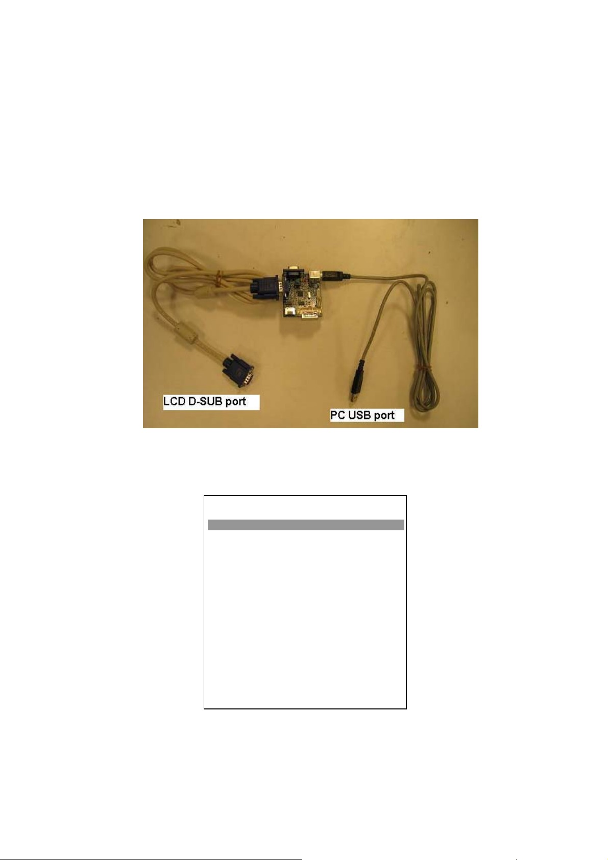
(1)
M-Star Debug board X1, USB cable X1, PC D-Sub cable X1
Follow below connecter function with PC and LCD TV.
Turn on LCD TV then press the “Mute” (remote control) and “Menu” (key pad) to enter factory mode.
(2)
Setup Service Mode form “ON” to "Off".
FACTORY MENU
Cool
Warm
Normal
Shipping
NV Clear
Full Power
uto Calibration
RF Burn In
Service Mode
Reset
OK
OK
OK
< Factory >
OK
OK
>
< Off >
< Off >
OK
Board Name: L19112_Rev.1
VERSION: SSA19C-WXGA V1.0
04/10/09 00:00:00
14
Page 15
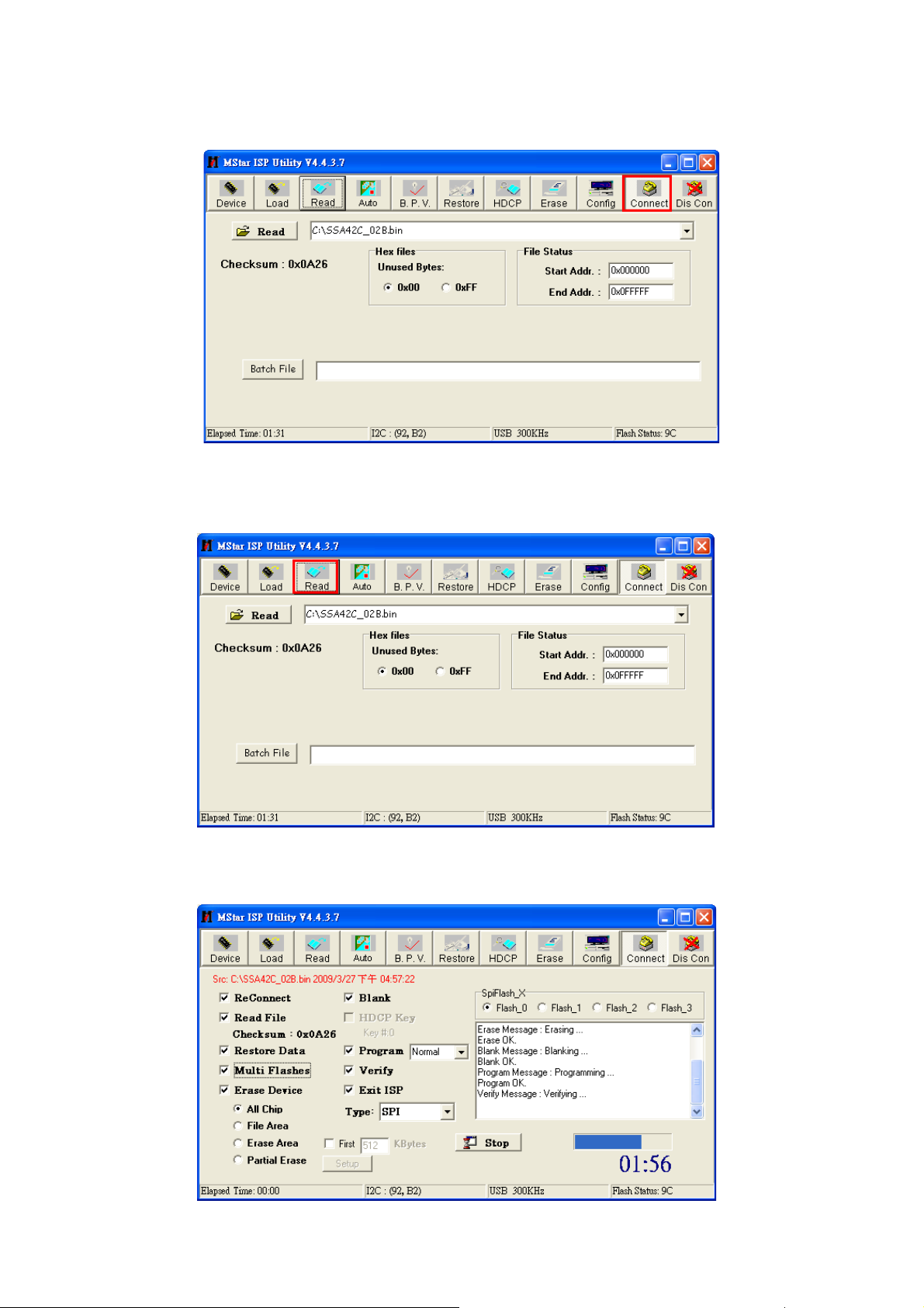
(3) Execute ISP_Tool.exe file and press “Connect” button.
Fig3 the written file
(4) Press Read file to loading the F/W. ex:SSAXXC.bin
(5) Click “Auto”, and press “Run” button to upgrade F/W
15
Page 16
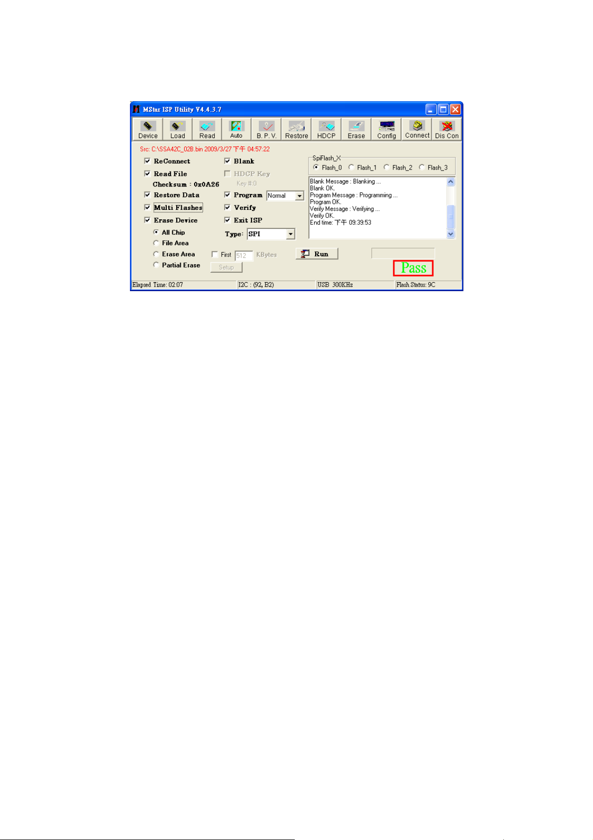
(6) If the process of writing succeeds, it will display “Pass” near “Run”..
(7) Repeat step 2) and 5) to write the program to the other units without exit the ISP interface.
16
Page 17

Working principle analysis of the unit
1. PAL/SECAM signal flow:
Antenna reception PAL/NTSC/SECAM signal will be send to tuner TAFT-Z711D,
will be
TV-CVBS will send to the master control IC MST9A881 or MST9B881 to video decode, de-interlace
and scaler, then output LVDS level drive for panel display.
The sound IF (SIF) will be fed into MST9A881 or MST9B881, after demodulating, pre-amplifying,
bass adjusting and volume control, the sound signal will
signal by
way will be sent to earphone amplifier TPA6111, another will be sent to speaker.
2. AV/SV signal flow
SV signal and the Video1 path AV signal switch
input”
MST9B881 to perform video decode, de-interlace and scaler, then output LVDS drive level for panel
display.
Audio signal from AV/SV
adjust and volume control, the sound signal will be
sent to digital amplifier TAS5706 amplifying, then output two ways. One way will be sent to earphone
amplifier TPA6111, another will be sent to speaker.
3. PC/YPrPb signal flow
PC and the Video3 path YPbPr signal are via terminal sent to MST9A881 or MST9B881 A/D
conversion, output R/G/B of 24 bit to back end module to digital decode, image scale, then send
to LVDS level drive for panel display.
Sound signal of PC/YPrPb
MST9B881 to bass adjust and volume control, the sound signal will be transform into digital I2S signal
by scaler IC and sent to digital amplifier TAS5706 amplifying, then output two ways. One way will be
sent to earphone amplifier TPA6111, another will be sent to speaker.
demodulating and output standard video signal TV-CVBS and sound IF signal (SIF).
be transform into digital I2S
scaler
IC
and sent to digital amplifier TAS5706 amplifying, then output two ways. One
by menu “Setup”->“AV Connecting”->”Video1
via terminal socket, the signal and the Video2 path AV signal will be fed to MST9A881 or
terminal
terminal
via matched resistance is fed to MST9A881 or MST9B881 to bass
transform into digital I2S signal by scaler IC
via matched resistance
and
sent to MST9A881 or
then Tuner
and
4. HDMI signal flow
Three HDMI video signals via switcher Sil9185 are directly fed to the master control IC MST9A881
or MST9B881(19” directly into master control IC MST9A881) to digital decode, image scale, then
output LVDS drive level for panel display. HDMI audio signal via decoder built-in MST9A881 or
be
MST9B881 is fed to back end to bass adjust and volume control, the sound signal will
into digital I2S signal by scaler IC and sent to digital amplifier TAS5706 amplifying, then output two
ways. One way will be sent to earphone amplifier TPA6111, another will be sent to speaker.
transform
17
Page 18

Block diagram-ELECTRON-19”26”32”42”
18
Page 19
Block diagram-POWER-19”
19
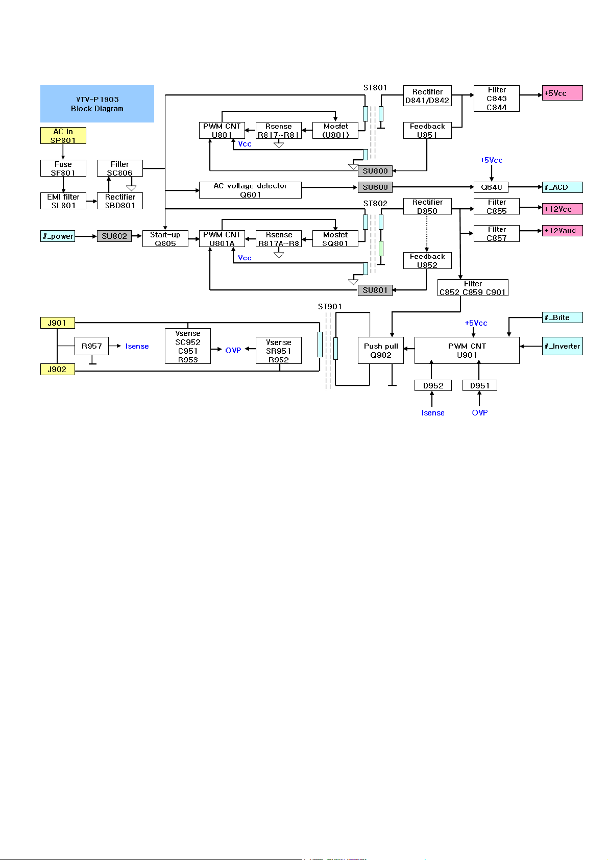
Page 20

Block diagram-POWER-26”32”42”
ͷʹ
ͳΣΠΨΟΠΦ Υ
· ΒΦΩ
΄
͵ʹ͵ʹ
Β ΝΗΓ ΣΚΕΘ Ζ
· ΚΟΧ
· ΒΦΕ
· ΔΔ
΄
͵ʹ͵ʹ
ͷΝΪ ΓΒΔ Μ
ΐ Ͳʹ͵
ΐ ΡΠ ΨΖΣ
ΐ ΚΟΧΖΣΥ ΖΣ
ΐ ΕΚΞΞΖ Σ
·
·
·ΒΦΕ ·ΚΟΧ
ΐͲʹ͵
ΐΡΠΨΣ ΐΚΧ Ζ ΣΥ ΖΣ ΐΕΚ Ξ Ξ ΖΣ ΐ ΚΧΖ Σ ΥΖ ΣΐΕΚΞΞΖΣ
΅ΠΞΒΚΟΓΠΒΣΕ
· Δ Δ
ΐ ΚΟ ΧΖΣ ΥΖΣ
ΐ ΕΚΞΞ ΖΣ
΅ΠΚΟΧΖΣΥΖΣΓΠΒΣΕ
20
Page 21

IC block diagram
1. MST9A881/MST9B881
Feature
z Input supports up to SXGA (MST9A881) & UXGA (MST9B881) &1080P.
z Panel supports up to SXGA (1280X1024 for MST9A881)/WXGA + (1440X900 for MST9A881)/
Full HD (1920X1080 for MST9B991).
z TV decoder with 3-D comb filter.
z Multi-standard TV sound demodulator and decoder.
z 10-bit triple-ADC for TV and GRB/YPbPr.
z 10-bit video data processing.
z Automatic color calibration.
z Integrated DVI/HDCP/HDMI compliant receiver.
z High-quality scaling engine & 3-D video de-interlacer.
z 3-D video noise reduction.
z MstarACE-3 picture/color processing engine.
z Embedded On-Screen Display (OSD) controller engine.
z Built-in MCU supports PWM & GPIO.
z Built-in dual-link 8-bit LVDS transmitter.
z 5-volt tolerant inputs.
z Low EMI and power saving features.
NTSC/PAL/SECAM Video Decoder
z Support NTSC M,NTSC-J,NTSC-4.43,PAL(B,D,G,H,M,N,I,Nc), and SEAM.
z Automatic TV standard detection.
z Supports Teletext level-1.5, WSS, VPS.
z CVBS video output
Multi-Standard TV Sound Decoder
z Supports BTSC/NICAM/A2/EIA-J demodulation and decoding.
z FM stereo & SAP demodulation.
z Built-in audio output DAC’s.
z Audio processing for loudspeaker channel, including volume, balance, mute, tone, EQ, and
Virtual stereo/surround.
Digital Audio Interface
2
z I
z HDMI audio channel processing capability.
z Programmable delay for audio/video synchronization.
DVI/HDCP/HDMI Compliant Input Port
z Supports TMDS clock up to 225MHz @ 1080P 60Hz with 12bit deep-color resolution.
z Single link on-chip DVI 1.0 compliant receiver.
z HDCP 1.1 compliant receiver.
z HDMI 1.3 compliant receiver.
z Long-Cable tolerant robust receiving.
Video Processing & Conversion
z 3-D motion adaptive video de-interlacer.
z Edge-oriented adaptive algorithm for smooth low-angel edges.
z Automatic 3:2 pull-down & 2:2 pull-down detection and recovery.
z Programmable 12-bit RGB gamma CLUT
z 3-D video noise reduction.
z Frame rate conversion.
Integrated Micro Controller
z Embedded 8032 micro controller
z Low-speed ADC inputs for system control
z
S digital audio input & output.
Configurable PWM’s and GPIO’s
21
Page 22
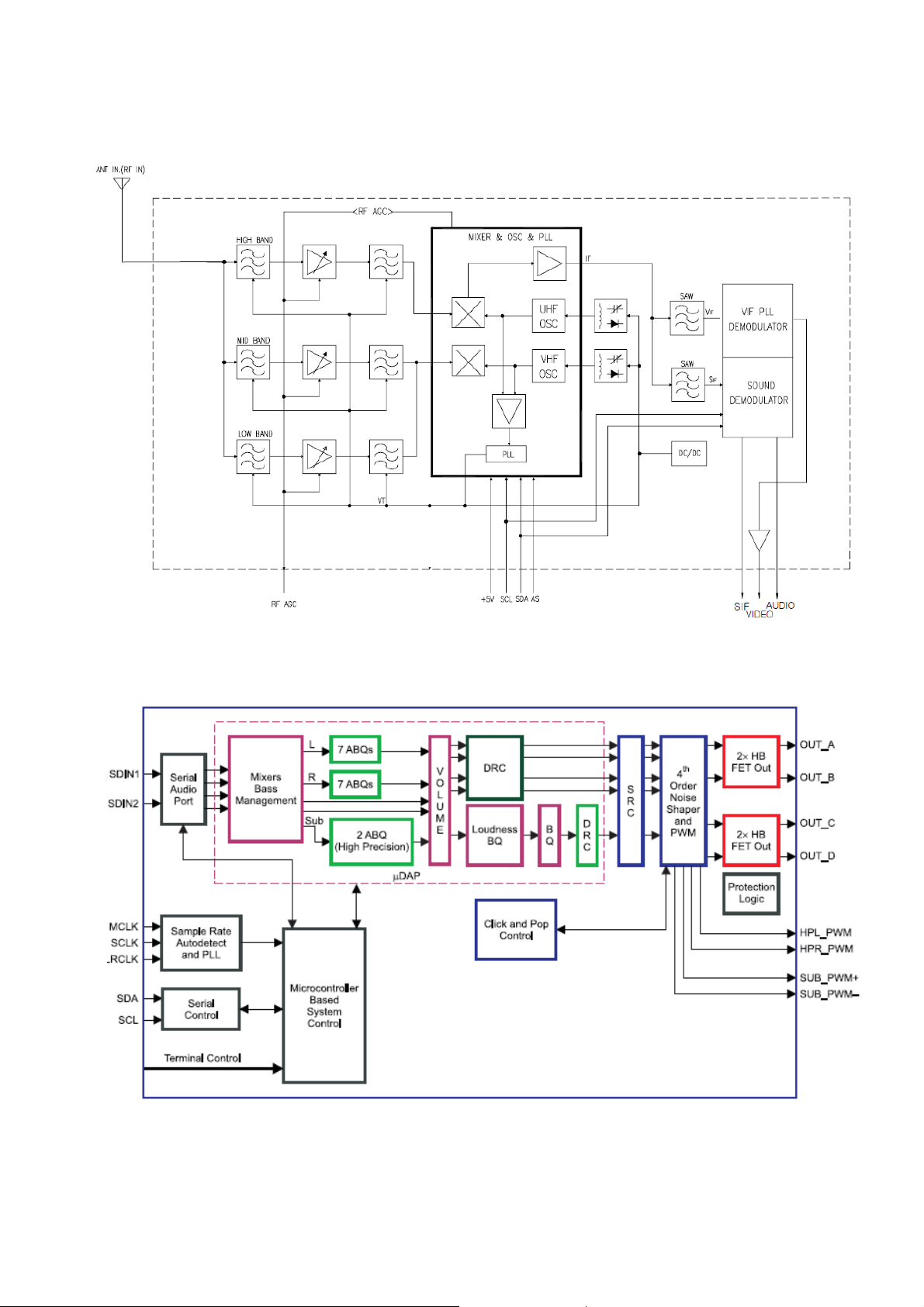
2. TAFT-Z711D
Multi Media Tuner 2IN1 Tuner with Analog Demodulator
3. TAS5706
Stereo Digital Audio Power Amplifier with EQ and DRC. Support Headphone PWM outputs.
22
Page 23

4. SIL9185
HDMI switch, three input, single output. Integrated EDID capability to lower system cost.
Control via local I2C but or stand-alone mode option.
23
Page 24

24
19” Block
Page 25

25
26”/32”/42” Block
Page 26

26
Wiring Connection
Page 27

Trouble shooting
1. Fault clearance
27
Page 28

2. Troubleshooting guide
The flow chart shown below will help you to troubleshoot your Televison set with it doesn’t display
normally. Each procedure offers a simple way to check for system errors. Before starting, ensure
that there is a signal in and that the Televison is turned on.
2-1 Power LED no light
Power LED no
Light
Check L21
+5V_IN
Change to new power board.
P/N : 453C0830L21 ( LCD19E30)
P/N : PK101V1090I ( LCD26E30)
P/N : PK101V1100I ( LCD32E30)
/or PK101V1180I
P/N : PK101V1110I ( LCD42E30F)
/or PK101V1170I
NG
OK
H
Check
CN2
Pin 2
Check
LED
Change MAIN
PCB
L
Change LED
PCB
NG
28
Page 29

2-2 Has audio but no video out
Change to new power board.
P/N : 453C0830L21 ( LCD19E30)
P/N : PK101V1090I ( LCD26E30)
P/N : PK101V1100I ( LCD32E30)
/or PK101V1180I
P/N : PK101V1110I ( LCD42E30F)
/or PK101V1170I
2-3 Has video but no audio out step 1
29
Page 30

2-4 Has video but no audio out step 2
Change to new power board.
P/N : 453C0830L21 ( LCD19E30)
P/N : PK101V1090I ( LCD26E30)
P/N : PK101V1100I ( LCD32E30)
/or PK101V1180I
P/N : PK101V1110I ( LCD42E30F)
/or PK101V1170I
30
Page 31

19”
ELECTRON
SCHEMATIC DIAGRAM
Page 32

1
3
4
LED1
8P
LS1
POWER ON/Standby>>>>>LED1
LIGHT SENSOR>>>>>>>>>LS1
COV1
COV1
1
GND
GND
GND
GND
GND
2
EMI-CASE-HOLE
EMI-CASE-HOLE
5
1
2
S1 POWER
3
IR
CN2
U8
LVDS 2X14
U17
CN4
160mm
U27
1.26V
PCBA IO POSITION
4
U18
PWR SW
CN5
POWER INPUT
KEYPAD/SIDE IO
58mm Limit high 22mm
S2 CH+
U13
2.6V
DDR/8Mx16
U15
FLASH/8MB
MST9B881GL-1
1.
U3
AUDIO AMP
Separate Ground
Speaker out
S3 CH-
SpearkerCN1
S5 VOL-
S4 VOL+
EMI Shield
HDMI1
200mm
S6 MENU
U28
IO9
RS232
IO8
PC:D-Sub
IO7
S7 INPUT/EXIT
U19
RS232-Driver
9P-RS232
IO5
15P_D-SUB
U5
TPA6111
12Vto8V
U20
Limit high 11mm
IO 1
Separate Ground
8Vto8V
PC/HDMI
Audio
RCA R/L
LG TAFT-Z711D
IO6
U6
Component/Monitor Out
Audio In/Line Out-R/L
IO 2
T2
S-VIDEO/CVBS Input
AUDIO IN-R/L
DRV601
910
H9
910
H4
910
H3
910
H2
910
11121314151617
11121314151617
11121314151617
11121314151617
2345678
1
H85D4.0-HIT-TRIH9H85D4.0-HIT-TRI
2345678
1
H8D34X44-TRIH4H8D34X44-TRI
2345678
1
H8D41X53-TRIH3H8D41X53-TRI
2345678
1
H8D34-TRIH2H8D34-TRI
2
3
4
SANYO ASIA model list:PCBA SIZE:200mmx160mm
2345678
1
H1
11121314151617
5
D D
C C
B B
H8D41X45-TRIH1H8D41X45-TRI
5
A A
Page 33

1
CVBS2_AURIN (6).
CVBS2_AULIN (6).
CVBS2 (6).
SV_C0 (6).
SV_Y0 (6).
C250 0.047uF/0402/50VC250 0.047uF/0402/50V
R278 47R/0402R278 47R/0402 C249 0.047uF/0402/50VC249 0.047uF/0402/50V
R279 47R/0402R279 47R/0402
2
FB44
FB44
KHB/0603/30/3A
KHB/0603/30/3A
C253
C253
12
SV_SW (6).
FB43
FB43
KHB/0603/30/3A
KHB/0603/30/3A
12
R277 1K/0603R277 1K/0603
4
3
1
2
Y
C
GND
GND
3
IO6
IO6
C257 2.2uF/0603/16VC257 2.2uF/0603/16V
R284 22K/0603R284 22K/0603
R28175R/0603/1%R28175R/0603/1%
C25410pF/0603/50V/5%C25410pF/0603/50V/5%
100pF/0603/50V/5%/NC
100pF/0603/50V/5%/NC
D63
D63
QV1AA10P-R05/NC
QV1AA10P-R05/NC
R28075R/0603/1%R28075R/0603/1%
10pF/0603/50V/5%
10pF/0603/50V/5%
C252
C252
100pF/0603/50V/5%/NC
100pF/0603/50V/5%/NC
C251
C251
D62
D62
QV1AA10P-R05/NC
QV1AA10P-R05/NC
YT
6
YS
5
SW
Y/C
GND
GND
VCOM2 (6).
HP_DET# (3).
HP_R (3).
C274 0.047uF/0402/50VC274 0.047uF/0402/50V
C259 2.2uF/0603/16VC259 2.2uF/0603/16V
C262 0.047uF/0402/50VC262 0.047uF/0402/50V
C282
C282
R295 47R/0402R295 47R/0402
R287 47R/0402R287 47R/0402
C273560pF/0603/50VC273560pF/0603/50V
C281
R29447K/0603 R29447K/0603
QV1AA10P-R05/NC
QV1AA10P-R05/NC
D66
D66
12
C27222pF/0603/50V/5%C27222pF/0603/50V/5%
C271560pF/0603/50VC271560pF/0603/50V
R29347K/0603 R29347K/0603
22pF/0603/50V/5%
22pF/0603/50V/5%
C270
C270
R286 22K/0603R286 22K/0603
12
R29275R/0603/1%R29275R/0603/1%
C269
C269
FB46
FB46
KHB/0603/30/3A
KHB/0603/30/3A
C268
C268
12
RT
RB
WT
WS
L
R
SW
GND
QV1AA10P-R05/NC
QV1AA10P-R05/NC
D65
D65
10pF/0603/50V/5%
10pF/0603/50V/5%
100pF/0603/50V/5%/NC
100pF/0603/50V/5%/NC
D64
D64
QV1AA10P-R05/NC
QV1AA10P-R05/NC
RS
GND
RCA/SV+YWR/V-JALCO
RCA/SV+YWR/V-JALCO
C281
C280
C280
C279
470pF/0603/50V
C279
470pF/0603/50V
C278
430pF/0603/50V/NC
C278
430pF/0603/50V/NC
12
D78
D78
12
D69
D69
12
D68
D68
6
7
8
IO3
IO3
4L5R
2L3R
HP_L (3).
0.1uF/0603/16V
0.1uF/0603/16V
470pF/0603/50V
470pF/0603/50V
L34
L34
3.3uH/KSI0603
3.3uH/KSI0603
430pF/0603/50V/NC
430pF/0603/50V/NC
3.3uH/KSI0603
3.3uH/KSI0603
L33
L33
3.3uH/KSI0603
3.3uH/KSI0603
L32
L32
C286
C286
QV1AA10P-R05/NC
QV1AA10P-R05/NC
QV1AA10P-R05/NC
QV1AA10P-R05/NC
QV1AA10P-R05/NC
QV1AA10P-R05/NC
DGND
9
10
11
1
EARPHONE/SW/KYOYAKU
EARPHONE/SW/KYOYAKU
C307
C307
FB47
FB47
KHB/0603/30/3A
KHB/0603/30/3A
TP34TP34
+8V_SW
VIDEO LINE OUT
CVBS_OUT (6).
LINE_ROUT (3).
R306
0R/0603
R306
0R/0603
R313
B
Q23
Q23
CE
C E
+
EC8
R308
R308
VIDEO_OUT
PMBT3904/SOT23
PMBT3904/SOT23
220uF/6D3/16V+EC8
220uF/6D3/16V
75R/0603/1%
75R/0603/1%
R313
12K/0603/NC
12K/0603/NC
R310
220R/0603
R310
220R/0603
D80
D80
12
R315
68R/0603
R315
68R/0603
QV1AA10P-R05/NC
QV1AA10P-R05/NC
R301
27K/0603/NC
R301
27K/0603/NC
R300
4.7K/0603
R300
4.7K/0603
B
Q21
Q21
PMBT3906/SOT23
PMBT3906/SOT23
0.1uF/0603/16V
0.1uF/0603/16V
10uF/0805/16V
10uF/0805/16V
LINE_LOUT (3).
100pF/0603/50V/5%
100pF/0603/50V/5%
C304
C304
C303
100pF/0603/50V/5%
C303
100pF/0603/50V/5%
FB51
FB51
FB52
FB52
KHB/0603/30/3A
KHB/0603/30/3A
KHB/0603/30/3A
KHB/0603/30/3A
C302
22pF/0603/50V/5%/NC
C302
22pF/0603/50V/5%/NC
SW PUSH/4PV/3.85MM
SW PUSH/4PV/3.85MM
1
C301
C301
AUDIO_LOUT
AUDIO_ROUT
22pF/0603/50V/5%/NC
22pF/0603/50V/5%/NC
S7
S7
SW PUSH/4PV/3.85MM
SW PUSH/4PV/3.85MM
S6
S6
24
3
1
24
3
AUDIO LINE OUT
SW PUSH/4PV/3.85MM
SW PUSH/4PV/3.85MM
1
24
3
S5
S5
SOG1 (6).
HD1_Y (6).
HD1_PB (6).
HD1_PR (6).
1
2
3
S-Video & CVBS+Audio
D61
D61
12
D60
D60
12
D59
D59
12
IO1
IO1
C255 2.2uF/0603/16VC255 2.2uF/0603/16V
R282 22K/0603R282 22K/0603
T1
GND
GND
S1
4
5
SIDE CVBS+Audio
SW PUSH/4PV/3.85MM
SW PUSH/4PV/3.85MM
1
24
KEYPAD
3
S4
S4
SW PUSH/4PV/3.85MM
SW PUSH/4PV/3.85MM
1
3
S3
S3
CH+POWER CH- VOL+ VOL- MENU INPUT/EXIT
SW PUSH/4PV/3.85MM
SW PUSH/4PV/3.85MM
1
3
S2
S2
SW PUSH/4PV/3.85MM
SW PUSH/4PV/3.85MM
1
3
S1
S1
CH- (6). VOL+ (6). VOL- (6). MENU (6). SOURCE (6).
24
4
CH+ (6).PWR_KEY (6).
24
24
5
A A
EARPHONE
SIDE_AURIN (6).
SIDE_AULIN (6).
SIDE_CVBS (6).
VCOM0 (6).
C267 0.047uF/0402/50VC267 0.047uF/0402/50V
C256 2.2uF/0603/16VC256 2.2uF/0603/16V
C258 0.047uF/0402/50VC258 0.047uF/0402/50V
R291
47R/0402
R291
47R/0402
R285
47R/0402
R285
47R/0402
560pF/0603/50V
560pF/0603/50V
C266
C266
47K/0603
47K/0603
R290
R290
22pF/0603/50V/5%
22pF/0603/50V/5%
C265
C265
QV1AA10P-R05/NC
QV1AA10P-R05/NC
R283 22K/0603R283 22K/0603
QV1AA10P-R05/NC
QV1AA10P-R05/NC
FB45
FB45
KHB/0603/30/3A
KHB/0603/30/3A
QV1AA10P-R05/NC
QV1AA10P-R05/NC
T2
B1
L
L
SWSWR
SWSWR
GND
GND
S2
560pF/0603/50V
560pF/0603/50V
C264
C264
47K/0603
47K/0603
R289
R289
22pF/0603/50V/5%
22pF/0603/50V/5%
C263
C263
75R/0603/1%
75R/0603/1%
R288
R288
10pF/0603/50V/5%
10pF/0603/50V/5%
C261
C261
100pF/0603/50V/5%/NC
C260
C260
B2
D D
100pF/0603/50V/5%/NC
T3
B3
SW
SW
Y/C
Y/C
GND
GND
S3
RCA/1X3/RWY/SW-JALCO
RCA/1X3/RWY/SW-JALCO
PC_AUL0 (6).
C275 2.2uF/0603/16VC275 2.2uF/0603/16V
R296 22K/0603R296 22K/0603
D67
D67
12
RST
R
L
R
L
IO5
IO5
PC/HDMI Audio Input
PC_AUR0 (6).
C283 2.2uF/0603/16VC283 2.2uF/0603/16V
560pF/0603/50V
560pF/0603/50V
C277
C277
47K/0603
47K/0603
R297
R297
22pF/0603/50V/5%
22pF/0603/50V/5%
R298 22K/0603R298 22K/0603
C276
C276
QV1AA10P-R05/NC
QV1AA10P-R05/NC
GND
GND
PHONE/3PV/BLK
PHONE/3PV/BLK
C285
C285
R299
R299
C284
C284
D70
D70
12
560pF/0603/50V
560pF/0603/50V
47K/0603
47K/0603
22pF/0603/50V/5%
22pF/0603/50V/5%
QV1AA10P-R05/NC
QV1AA10P-R05/NC
C C
C287 1nF/0402/50VC287 1nF/0402/50V
C290 0.047uF/0402/50VC290 0.047uF/0402/50V
C288 0.047uF/0402/50VC288 0.047uF/0402/50V
C289 0.047uF/0402/50VC289 0.047uF/0402/50V
R304 47R/0402R304 47R/0402
R302 47R/0402R302 47R/0402
R303 47R/0402R303 47R/0402
R307 47R/0402R307 47R/0402
FB48
FB48
D73
D73
KHB/0603/30/3A
KHB/0603/30/3A
12
QV1AA10P-R05/NC
QV1AA10P-R05/NC
FB49
FB49
D72
D72
12
D71
D71
12
KHB/0603/30/3A
KHB/0603/30/3A
QV1AA10P-R05/NC
QV1AA10P-R05/NC
FB50
FB50
KHB/0603/30/3A
KHB/0603/30/3A
QV1AA10P-R05/NC
QV1AA10P-R05/NC
VIDEO_OUT
T3
T8
T2
T1
Y
Y
IO7 RCA/2X5/YBRWR/XXYW R/SW/V
IO7 RCA/2X5/YBRWR/XXYW R/SW/V
Pr
Pb
Pr
Pb
Y/C
Y/C
(YPBPR/Monitor Out)+Audio Input/Output
75R/0603/1%
75R/0603/1%
R312
R312
10pF/0603/50V/5%
10pF/0603/50V/5%
C296
C296
C295
C295
R311
R311
C294
C294
C293
C293
R309
R309
C292
C292
C291
C291
AUDIO_LOUT
T9
L
L
HD1_AULIN (6).
430pF/0603/50V/NC
430pF/0603/50V/NC
75R/0603/1%
75R/0603/1%
10pF/0603/50V/5%
10pF/0603/50V/5%
C297 2.2uF/0603/16VC297 2.2uF/0603/16V
430pF/0603/50V/NC
430pF/0603/50V/NC
75R/0603/1%
75R/0603/1%
10pF/0603/50V/5%
10pF/0603/50V/5%
R316 22K/0603R316 22K/0603
430pF/0603/50V/NC
430pF/0603/50V/NC
12
AUDIO_ROUT
T5
T10
T4
L
L
R
R
R
R
HD1_AURIN (6).
C300 2.2uF/0603/16VC300 2.2uF/0603/16V
560pF/0603/50V
560pF/0603/50V
C299
C299
47K/0603
47K/0603
R317
R317
22pF/0603/50V/5%
22pF/0603/50V/5%
R318 22K/0603R318 22K/0603
C298
C298
D74
D74
QV1AA10P-R05/NC
QV1AA10P-R05/NC
SW
SW
B5
S5
S4
S3
SW
SW
B10
S10
S9
S8
S2
S1
B B
C306
C306
R319
R319
C305
C305
D75
D75
12
560pF/0603/50V
560pF/0603/50V
47K/0603
47K/0603
22pF/0603/50V/5%
22pF/0603/50V/5%
QV1AA10P-R05/NC
QV1AA10P-R05/NC
Page 34

1
RXD (6).
TXD (6).
1
R320
R320
Q27
Q27
CBE
PMBT3904/SOT23
PMBT3904/SOT23
UartSel (6).
1K/0402
1K/0402
2
TP38TP38
+5V_IN
D79
1N4148W
D79
1N4148W
C639
C639
C638
C638
C637
U28
U28
232 XCVR
232 XCVR
10
T1IN11T2IN
T1OUT14T2OUT
7
R275 0R/0402R275 0R/0402
9
R1OUT12R2OUT
R1IN13R2IN
8
R276 0R/0402R276 0R/0402
C637
4
C2+
C+1C1-
C635
C635
0.1uF/0402/16V
0.1uF/0402/16V
2
5
V+
C2-
V-
3
6
0.1uF/0402/16V
0.1uF/0402/16V
0.1uF/0402/16V
0.1uF/0402/16V
16
VCC
GND
15
C636
C636
0.1uF/0402/16V
0.1uF/0402/16V
1uF/0603/16V
1uF/0603/16V
3
SP232ACN-L/SO16
SP232ACN-L/SO16
4
UARTRX
UARTTX
VGA_VS (6).
VGA_HS (6).
R268 0R/0402R268 0R/0402
R269 0R/0402R269 0R/0402
2
VGA_B (6).
VGA_G (6).
VGA_R (6).
SOG (6).
R267 2.2K/0402R267 2.2K/0402
R266 100R/0402R266 100R/0402
R265 2.2K/0402R265 2.2K/0402
R264 100R/0402R264 100R/0402
C245 0.047uF/0402/50VC245 0.047uF/0402/50V
C246 0.047uF/0402/50VC246 0.047uF/0402/50V
C244 0.047uF/0402/50VC244 0.047uF/0402/50V
R257 47R/0402R257 47R/0402
3
4
R259 47R/0402R259 47R/0402
R258 47R/0402R258 47R/0402
C247 1nF/0402/50VC247 1nF/0402/50V
R260 47R/0402R260 47R/0402
R263
R263
R262
R262
R261
R261
D53
D53
12
D52
D52
12
D51
D51
12
D50
D50
75R/0402/1%
75R/0402/1%
75R/0402/1%
75R/0402/1%
75R/0402/1%
75R/0402/1%
QV1AA10P-R05/NC
QV1AA10P-R05/NC
QV1AA10P-R05/NC
QV1AA10P-R05/NC
QV1AA10P-R05/NC
QV1AA10P-R05/NC
1 2
MMSZ5232B/5V6/SOD-123
MMSZ5232B/5V6/SOD-123
VSI
HSI
+5V_IN
16
DA4DB
VCC
U2
S1A2S1B5S1C11S1D14S2A3S2B6S2C10S2D
R562 0R/0402R562 0R/0402
0R/0402
0R/0402
R563
R563
R273
R273
100R/0402
100R/0402
R272
R272
100R/0402
100R/0402
R271
4.7K/0402
R271
4.7K/0402
R270
4.7K/0402
R270
4.7K/0402
7
12
DC9DD
R564 0R/0402R564 0R/0402
R274
R274
10K/0402
10K/0402
U26
U26
C248 0.1uF/0402/16VC248 0.1uF/0402/16V
8
15
#EN
GND
IN
1
13
R565 0R/0402R565 0R/0402
EDID_WP (6).
7
8
VCC
VCLK
NC1NC2NC3GND
6
SCL
PI5V330/QSOP16U2PI5V330/QSOP16
5
SDA
4
+5V_IN
24C02/SOP8
24C02/SOP8
R321
10K/0402
R321
10K/0402
IO8
IO8
5
D-SUB INPUT
D57
D55
D55
1 2
+5V_PC
VGA_B+
VGA_G+
VGA_R+
1
2
3
4
5
9
10
14
15
6
7
8
1
1
6
6
16 17
11
11
11
12
13
DSUB-15P/FEMALE/V
DSUB-15P/FEMALE/V
MMSZ5232B/5V6/SOD-123
MMSZ5232B/5V6/SOD-123
D54
D54
1 2
MMSZ5232B/5V6/SOD-123
MMSZ5232B/5V6/SOD-123
D57
1 2
MMSZ5232B/5V6/SOD-123
MMSZ5232B/5V6/SOD-123
D56
D56
1 2
MMSZ5232B/5V6/SOD-123
MMSZ5232B/5V6/SOD-123
D58 BAT54C/SOT-23D58 BAT54C/SOT-23
132
TP33TP33
+5V_PC
Tx
+5V_IN
Rx
594837261
IO9
IO9
10
11
RS232-9P/FEMALE/V
RS232-9P/FEMALE/V
5
RS232 INPUT
VSI
HSI
D D
C C
B B
A A
Page 35

1
TUNER_CVBS (6).
VCOM1 (6).
SIFP
SIFM
2
I2C_SCL (3,5,6).
I2C_SDA (3,5,6).
I2C_SCL
I2C_SDA
C225
C225
100pF/0402/50V/5%/NC
3
C223
C223
C222
C222
4
100pF/0402/50V/5%/NC
C224
C224
100pF/0402/50V/5%/NC
100pF/0402/50V/5%/NC
R216 22R/0402R216 22R/0402
R217 22R/0402R217 22R/0402
47pF/50V/0402/5%
47pF/50V/0402/5%
SDA
SCL
47pF/50V/0402/5%
47pF/50V/0402/5%
R218
0R/0402/NC
R218
0R/0402/NC
AS
C228
0.1uF/0402/16V
C228
C226
C226
R219 47R/0402R219 47R/0402
SIF
0.1uF/0402/16V
0.1uF/0402/16V
0.1uF/0402/16V
R222 47R/0402R222 47R/0402
Q17
PMBT3904/SOT23
Q17
PMBT3904/SOT23
R223
R223
+5V_TUNER
CBE
22K/0402
22K/0402
+
+
EC20
EC20
47uF/6D3/16V
47uF/6D3/16V
VS_RF
+
+
100uF/6D3/16V
100uF/6D3/16V
EC10
EC10
FB37
FB37
KHB/0603/30/3A
KHB/0603/30/3A
+
+
100uF/6D3/16V
100uF/6D3/16V
EC9
EC9
C227
C227
R220
R220
TU_CVBS
+5V_TUNER
22pF/0402/50V/5%
22pF/0402/50V/5%
2.2K/0402/NC
2.2K/0402/NC
R221
75R/0402/1%
R221
75R/0402/1%
C230
C230
R225 47R/0402R225 47R/0402
CVBS
R224 0R/0402R224 0R/0402
C232
0.1uF/0402/16V
C232
0.1uF/0402/16V
0.1uF/0402/16V
0.1uF/0402/16V
R228 47R/0402R228 47R/0402
C231
330pF/0402/50V/5%/NC
C231
330pF/0402/50V/5%/NC
R227
2.2K/0402
R227
2.2K/0402
+5V_TUNER
R229 0R/0402/NCR229 0R/0402/NC
22K/0402
22K/0402
VS_IF
+
+
100uF/6D3/16V/NC
100uF/6D3/16V/NC
EC14
EC14
FB57
FB57
KHB/0603/30/3A/NC
KHB/0603/30/3A/NC
+
+
100uF/6D3/16V/NC
100uF/6D3/16V/NC
EC13
EC13
R226
R226
VS_IF
FB58
FB58
KHB/0603/30/3A/NC
KHB/0603/30/3A/NC
5V-IF
VIF_12V
VIF_12V
R232
R232
150R/0402/1%/NC
150R/0402/1%/NC
FB39
FB39
KHB/0603/30/3A/NC
KHB/0603/30/3A/NC
TP32TP32
12VCCIN
SIFP (6).
SIFM (6).
SIFP
SIFM
R241
R241
R245
R245
0R/0402/NC
0R/0402/NC
0R/0402/NC
0R/0402/NC
4
5
SIF
OUT1
OUT2
C551
0.1uF/0402/16V/NC
C551
0.1uF/0402/16V/NC
C550
1nF/0402/50V/NC
C550
1nF/0402/50V/NC
R237
R237
10K/0402/NC
10K/0402/NC
R236
R236
4.7K/0402/NC
4.7K/0402/NC
R235
R235
4.7K/0402/NC
4.7K/0402/NC
R234
680R/0402/NC
R234
680R/0402/NC
FB40
FB40
C237
C237
R233
4.7K/0402/NC
R233
4.7K/0402/NC
C236
C236
C235
C235
GND
3
SAW
SAW
ING
IN
SAW1
K9655D/P2.54/5P/NC
SAW1
K9655D/P2.54/5P/NC
2
1
D49
BA277/SOD523/NC
D49
BA277/SOD523/NC
R244
4.7K/0402/NC
R244
4.7K/0402/NC
C238
C238
10nF/0402/16V/NC
10nF/0402/16V/NC
R239
39R/0603/NC
R239
39R/0603/NC
0.82uH/0805/NC
0.82uH/0805/NC
PBR941/SOT23/NC
PBR941/SOT23/NC
CE
Q18
Q18
B
R238
1.2K/0402/NC
R238
1.2K/0402/NC
10nF/0402/16V/NC
10nF/0402/16V/NC
10nF/0402/16V/NC
10nF/0402/16V/NC
R243
56R/0402/NC
R243
56R/0402/NC
10uF/0805/16V/NC
10uF/0805/16V/NC
C239
C239
IF_TV
10nF/0402/16V/NC
10nF/0402/16V/NC
R242
R242
0R/0402/NC
0R/0402/NC
IF_TVP
R248
R248
R247
R247
R246
R246
5V-IF
0R/0402/NC
0R/0402/NC
R250
R250
1K/0402/NC
1K/0402/NC
75R/0402/1%/NC
75R/0402/1%/NC
R249
R249
22K/0402/NC
22K/0402/NC
Q20
Q20
DGS
10R/0402/NC
10R/0402/NC
SIF_CTL (6).
SIF_CTL
C240
10nF/0402/16V/NC
C240
10nF/0402/16V/NC
R251
220K/0402/NC
R251
220K/0402/NC
R252
R252
220K/0402/NC
220K/0402/NC
2N7002/SOT23/NC
2N7002/SOT23/NC
R508
R508
5V-IF
R507
R507
R506
R506
VIFP (6).
VIFM (6).
VIFP
VIFM
R253 0R/0402/NCR253 0R/0402/NC
C241 10pF/0402/50V/NCC241 10pF/0402/50V/NC
FB42
2.2uH/NC
FB42
2.2uH/NC
5
OUT2
SAW
SAW
SAW2
SAW2
IN
K7262D/P2.54/5P/NC
K7262D/P2.54/5P/NC
1
10K/0402/NC
10K/0402/NC
D77
D77
4.7K/0402/NC
4.7K/0402/NC
4.7K/0402/NC
4.7K/0402/NC
C242
C242
10nF/0402/16V/NC
10nF/0402/16V/NC
5V-IF
SIF_CTL
R511
22K/0402/NC
R511
R255 0R/0402/NCR255 0R/0402/NC
22K/0402/NC
C552
10nF/0402/16V/NC
C552
C243 10pF/0402/50V/NCC243 10pF/0402/50V/NCR230
10nF/0402/16V/NC
4
R512
220K/0402/NC
R512
OUT1
GND
3
ING
2
220K/0402/NC
R513
220K/0402/NC
R513
220K/0402/NC
DGS
Q24
BA277/SOD523/NC
BA277/SOD523/NC
FB59
1uH/0603/NC
FB59
1uH/0603/NC
R509
R509
51R/0603/1%/NC
51R/0603/1%/NC
D48 1N4148W/NCD48 1N4148W /NC
Q24
R256
R256
0R/0402/NC
0R/0402/NC
2N7002/SOT23/NC
2N7002/SOT23/NC
R510
R510
4.7K/0402/NC
4.7K/0402/NC
TAGC (6).
TAGC
12K/0402/NC
12K/0402/NC
R231
R231
0.1uF/0402/16V/NC
0.1uF/0402/16V/NC
C234
C234
100R/0402/NC
R230
100R/0402/NC
0.1uF/0402/16V/NC
0.1uF/0402/16V/NC
C233
C233
IF_AGC
1
2
3
4
C546
0.1uF/0402/16V
C546
0.1uF/0402/16V
SIF
SIF
TU_CVBS
VS_RF
IF_AGC
VS_RF
2
4
10
3
6
9
8
5
7
Vt
NC1NC
NC
GND
GND
5
T3
D D
RF AGC
GND
Vp(+5V)
VS_IF
SCL
SDA
AS
11
AS
NC
12
SCL
13
NC14NC15NC16NC17NC
SDA
R490 0R/0402/NCR490 0R/0402/NC
TP36TP36
R491 0R/0402/NCR491 0R/0402/NC
24
18
21
19
22
23
2IF20NC
CVBS
AS_IF
+5V_IF
AF-MPX
BODY25BODY26BODY27BODY
FQ1116PN/NCT3FQ1116PN/NC
28
C C
SDA
3
6
2
4
7
5
NC1NC
GND
GND
B+(5V)
RF AGC
T2
C545
C545
SCLASIF_TVP
8
DATA
CLOCK
TU_CVBS
1nF/0402/50V
1nF/0402/50V
0.1uF/0402/16V
0.1uF/0402/16V
R497 0R/0402R497 0R/0402
C400
C400
VIDEO_OUT
10
16
9
11
AS
NC
NC12NC13NC14NC15NC
IF OUT
GND17GND18GND19GND
TAET-Z711DT2TAET-Z711D
20
B B
A A
5
Page 36

BKLT_EN
C215
D
D
S
S
2.2K/0603
2.2K/0603
1K/0603
1K/0603
C215
R547
R547
G
G
C205
C205
Q14
Q14
CBE
0.1uF/0603/16V/NC
0.1uF/0603/16V/NC
2.2K/0603
2.2K/0603
AC_OFF
10uF/0805/16V
10uF/0805/16V
PMBT3904/SOT23
PMBT3904/SOT23
OPC_OUT (6).
OPC_EN (6,7).
VBR_OUT
S
S
Q2
Q2
SI2305DS/SOT-23
SI2305DS/SOT-23
G
G
D
D
R552
R552
0R/0603/NC
0R/0603/NC
R211
0R/0603
R211
0R/0603
ADJ_PWM(6).
1
2
A2001WV2-16P
A2001WV2-16P
Q19
Q19
+5V_SW
D
D
SI2305DS/SOT-23
SI2305DS/SOT-23
S
S
+5V_IN
G
G
R199
10K/0603
R199
10K/0603
C216
C216
0.1uF/0603/16V
0.1uF/0603/16V
R200
R200
1K/0603
1K/0603
+
+
EC28
EC28
22uF/5D/16V
22uF/5D/16V
R214
R214
1K/0603
1K/0603
D
POWER_EN
Q16
2N7002/SOT23
Q16
2N7002/SOT23
S
G
EC12
22uF/5D/16V+EC12
22uF/5D/16V
+
Q13
SI2305DS/SOT-23
Q13
SI2305DS/SOT-23
R215
0R/0603
R215
0R/0603
Q12
PMBT3904/SOT23
Q12
PMBT3904/SOT23
CBE
R202
R202
10K/0603
10K/0603
+5V_IN
+5V_SW
R209
R209
R206
R206
123456789101112131415
CN5
CN5
1
12V_AUDIO
12V_AUDIO
5V_IN
L17
L17
2.2uH/LS0403/3.8A
2.2uH/LS0403/3.8A
4.7K/1206
4.7K/1206
12V_IN
4.7K/1206
4.7K/1206
4.7K/1206
4.7K/1206
12V_IN
FBMA/1206/30/6A
FBMA/1206/30/6A
L20
L20
L22
L22
12VCCIN
R198
R198
R197
R197
R196
R196
TP37TP37
2
12VCCIN_AUDIO
5V_IN
FBMA/1206/30/6A/NC
FBMA/1206/30/6A/NC
5V_IN
L21
L21
AC_OFF
POWER_EN
VBR_OUT
FBMA/1206/30/6A
FBMA/1206/30/6A
AC_OFF(3,6).
+5V_IN
16
BKLT_EN
C543 0.1uF/0603/16VC543 0.1uF/0603/16V
POWER CON
3
TP25TP25
L18
L18
U20
78D05L/TO252
U20
12VCCIN
+8V_SW
U19
U19
R518 22R/2512R518 22R/2512
78D05L/TO252
FB36
FB36
78D08AL/TO252
78D08AL/TO252
4
5
TUNER POWER
+5V_TUNER
KHB/0603/30/3A
KHB/0603/30/3A
C194
C194
3
OUT
C
IN
1
C196
C196
C199
C199
KHB/0603/30/3A
KHB/0603/30/3A
C193
C193
C197
C197
3
OUT
C
IN
1
C544
C544
22R/2512
22R/2512
R519
R519
0.1uF/0603/16V
0.1uF/0603/16V
2
0.1uF/0603/16V
0.1uF/0603/16V
10uF/0805/16V
10uF/0805/16V
0.1uF/0603/16V
0.1uF/0603/16V
10uF/0805/16V
10uF/0805/16V
2
0.1uF/0603/16V
0.1uF/0603/16V
D D
POWER EN/SWITCH 5V
+1.26V
TP27TP27
EC25
KHB/0603/30/3A
KHB/0603/30/3A
+
+
C541
C541
3.3uH/CORE4.3/1.4A
3.3uH/CORE4.3/1.4A
D76
SR54/DO214
D76
SR54/DO214
KHB/0603/30/3A
KHB/0603/30/3A
7
LX
FB
EN
COMP
6
C538
C538
EC25
THERMAL
GND
3.3nF/0603/50V
3.3nF/0603/50V
+5V_IN
FB53
FB53
C536
C536
KHB/0603/30/3A
KHB/0603/30/3A
1
C535
C535
10uF/0805/16V
10uF/0805/16V
1uF/0603/16V
1uF/0603/16V
3
UGND
VIN
VCC
U27
U27
4
C537 1uF/0603/16VC537 1uF/0603/16V
FB55
FB55
L35
L35
FB54
FB54
5
2
R481 10K/0603R481 10K/0603
CODE POWER
C C
220uF/6D3/16V
220uF/6D3/16V
9
8
PWRON(6).
15K/0603/1%
15K/0603/1%
R482
R482
R483
R483
C540
C540
APW7080/SOP8
APW7080/SOP8
R480
6.2K/0603
R480
6.2K/0603
C539
C539
22pF/0603/50V/5%
22pF/0603/50V/5%
10uF/1206/16V/NC
10uF/1206/16V/NC
0R/0603
0R/0603
270pF/0603/50V
270pF/0603/50V
R484
24.9K/0603/1%
R484
24.9K/0603/1%
R207
10K/0603
R207
10K/0603
R208
10K/0603
R208
10K/0603
KHB/0603/30/3A
KHB/0603/30/3A
4
1
GND
KHB/0603/30/3A
KHB/0603/30/3A
B B
LCD_ON(6).
C204
0.1uF/0603/16V
C204
0.1uF/0603/16V
EC22
EC22
22uF/4D/6.3V
22uF/4D/6.3V
+
+
C202
0.1uF/0603/16V
C202
0.1uF/0603/16V
+
+
EC26
EC26
22uF/5D/16V
22uF/5D/16V
BLACK LIGHT CONTROL
+3.3V_SW+5V_SW
L26
L26
Vout2Vout
Vin
U23
LD1117/SOT223/3.3V
U23
LD1117/SOT223/3.3V
3
L25
L25
SWITCH 3.3V
PWM CONTROL
+3.3V_STB+5V_IN
TP29TP29
L28
KHB/0603/30/3A
L28
KHB/0603/30/3A
C206
0.1uF/0603/16V
C206
0.1uF/0603/16V
EC21
EC21
22uF/4D/6.3V
22uF/4D/6.3V
+
+
4
Vout2Vout
1
GND
Vin
U24
UZ1084L/TO263/3.3V
U24
UZ1084L/TO263/3.3V
3
C208
0.1uF/0603/16V
C208
0.1uF/0603/16V
+
+
EC27
EC27
22uF/5D/16V
L27
L27
KHB/0603/30/3A
KHB/0603/30/3A
STADY BY 3.3V
22uF/5D/16V
A A
3
4
5
Page 37

ٙٙ
ٙ
Ղ
ՂՂ
Ղٙ
1
R194
4.7K/0402/NC
R194
4.7K/0402/NC
R195
R195
0R/0402
0R/0402
(8).
OPC_OUT
1
+3.3V_SW
SEL1:
for AU panel 26/32"
Low=normal high=JEIDA R195
LG-19">>>>R195 NC
2
Panel list:20081205
LG-19" LC190WH1-TLC1 CAS_Sanyo_Ver1.0_081128.pdf
AU-26"T260XW02(VQ) Ver 0.0_Spec_20080829.pdf
PNL_PWR
CONNECT TO PANEL BOARD
EC5
EC5
100uF/6D3/16V/NC
100uF/6D3/16V/NC
+
+
L15
L15
FBMA/1206/30/6A
FBMA/1206/30/6A
3
D8D7D6D
S1S2S3G
U18
AO4435/P-CHANNEL/SOIC-8
U18
AO4435/P-CHANNEL/SOIC-8
4
C189
0.1uF/0402/16V
C189
0.1uF/0402/16V
C192
C192
5
10uF/0805/16V
10uF/0805/16V
4
C187
0.1uF/0402/16V
C187
0.1uF/0402/16V
R189
10K/0402
R189
10K/0402
AU32"T315XW02(VS) v0_081508.pdf
PMBT3904/SOT23
R191
R191
C190
0.1uF/0402/16V/NC
C190
0.1uF/0402/16V/NC
1K/0402
1K/0402
CE
Q10
Q10
R192
R192
PMBT3904/SOT23
B
47K/0402
47K/0402
CE
EC11
EC11
+
+
PNL_PWR
CN4
CN4
29
22uF/5D/16V
22uF/5D/16V
SEL1
LVDS_PWMOUT
2423
26252830
1917151311
27
LRXE2-
LRXEC-
LRXE1-
LRXE0+
LRXE0-
LRXE1+
LRXE2+
CM7
CM7
24681012141618202221
97531
A2006WV0-2X15P
A2006WV0-2X15P
LRXE4+
LRXE4-
LRXE3-
LRXE3+
LRXEC+
LRXE1-
LRXE0+
LRXE0-
5
6
7
QTC28CE121U/1012D
QTC28CE121U/1012D
RXE0-
RXE0+
312
RXE1-
LRXE1+
8
4
RXE1+
0R/0402/NC
0R/0402/NC
R558
R558
R551
R551
0R/0402
0R/0402
LRXE2-
LRXE2+
5
6
CM9
QTC28CE121U/1012D
CM9
QTC28CE121U/1012D
RXE2-
RXE2+
LRXEC-
LRXEC+
7
8
4
312
RXEC-
RXEC+
LRXE3-
LRXE3+
5
6
CM11
QTC28CE121U/1012D
CM11
QTC28CE121U/1012D
RXE3+
RXE3-
LRXE4-
7
312
RXE4-
LRXE4+
8
4
RXE4+
2
3
4
R190
C186
0.1uF/0402/16V
C186
0.1uF/0402/16V
C185
C185
10uF/0805/16V
10uF/0805/16V
L16
L16
L14
L14
FBMA/1206/30/6A
FBMA/1206/30/6A
FBMA/1206/30/6A/NC
5
TP22TP22
FBMA/1206/30/6A/NC
12VCCIN
D D
TP23TP23
+5V_SW
R190
10K/0402
10K/0402
26" 32" PANEL USE 12V
19" PANEL USE 5V
Q11
Q11
C C
B
PMBT3904/SOT23
PMBT3904/SOT23
R193 4.7K/0402R193 4.7K/0402
ON_PANEL(6).
RXE0-(6).
RXE0+(6).
RXE1-(6).
RXE1+(6).
B B
RXE2-(6).
RXE2+(6).
RXEC-(6).
RXEC+(6).
RXE3-(6).
RXE3+(6).
RXE4-(6).
RXE4+(6).
5
A A
Page 38

0V
1.055V
2.268V2.268V
VOL-_1
MENU_1
IR CON
CN2
CN2
1234567
8
A2001WV2-8P
LIGHT_SENSOR
C120 0.1uF/0402/16VC120 0.1uF/0402/16V
FB62 KHB/0603/30/3AFB62 KHB/0603/30/3A
IRDATA
FB64 KHB/0603/30/3AFB64 KHB/0603/30/3A
FB63 KHB/0603/30/3AFB63 KHB/0603/30/3A
LED_R
LED_G
FB65 KHB/0603/30/3AFB65 KHB/0603/30/3A
LED_C
A2001WV2-8P
C648
C648
C649
C649
C647
C647
C646
C646
C645
C645
C643
C643
C642
C642
C644
C644
1
C640
0.1uF/0402/16V
C640
0.1uF/0402/16V
C113 1uF/0805/50VC113 1uF/0805/50V
FB19 KHB/0603/30/3AFB19 KHB/0603/30/3A
FB61 KHB/0603/30/3AFB61 KHB/0603/30/3A
+5V_IN
+3.3V_STB
EEPROM
R1594.7K /0402 R1594.7K/0402
R1584.7K /0402 R1584.7K/0402
100pF/0402/50V/5%/NC
100pF/0402/50V/5%/NC
100pF/0402/50V/5%/NC
100pF/0402/50V/5%/NC
100pF/0402/50V/5%/NC
100pF/0402/50V/5%/NC
100pF/0402/50V/5%/NC
100pF/0402/50V/5%/NC
100pF/0402/50V/5%
100pF/0402/50V/5%
100pF/0402/50V/5%
100pF/0402/50V/5%
100pF/0402/50V/5%
100pF/0402/50V/5%
100pF/0402/50V/5%
100pF/0402/50V/5%
C145
C145
+5V_IN
I2C address
at A0.
0.1uF/0402/16V
0.1uF/0402/16V
8
U16
U16
VCC
A01A12A23GND
KEYADC
R405
R405
+3.3V_STB+3.3V_STB
I2C_SDA
I2C_SCL
7
6
5
WP
SCL
SDA
IS24C32A/32K/SOP8
IS24C32A/32K/SOP8
4
R400
R400
SOURCE_1
22K/0402
22K/0402
4.7K/0402
4.7K/0402
0R/0402
10K/0402
10K/0402
10K/0402
10K/0402
0R/0402
R406
R406
R407
R407
R408
R408
SV_SW (11).
AMP_SD (3).
HDMI_CEC (5).
PWRON (8).
ON_PANEL (7).
LCD_ON (8).
AMP_MUTE (3).
EDID_WP (5,10).
RESETN ( 3,5).
SIF_CTL (9).
R162
10K/0402
R162
MADR[0..11]
MADR[0..11] (4).
WEZ
R161
R161
CASZ (4).
WEZ (4).
CASZ
RASZ
10K/0402
10K/0402
MVREF
Memory
INTERFACE
RASZ (4).
BA1 (4).
MCLK (4).
BA0 (4).
MCLKZ
MCLK
BA1
BA0
10K/0402
C159
1nF/0402/50V
C159
1nF/0402/50V
C158
C158
0.1uF/0402/16V
0.1uF/0402/16V
GPIO Control Pins
CKE (4).
UDQM (4).
LDQM (4).
DQS1 (4).
MCLKZ (4).
DQS0 (4).
LDQM
CKE
DQS0
DQS1
UDQM
+3.3V_STB
R409
0R/0402
R409
0R/0402
KEY_ADC1
CH+_1
CH-_1
1.055V
4.7K/0402
4.7K/0402
22K/0402
22K/0402
R403
R403
R402
R402
R401
R401
R404
0R/0402
R404
0R/0402
KEY_ADC2
VDDM
VOL+_1
0V
0R/0402
0R/0402
MDATA[0..15] (4).
MDATA[0..15]
R41210K/0402 R41210K/0402
R41110K/0402 R41110K/0402
R41010K/0402 R41010K/0402
R50410K/0402 R50410K/0402
R50310K/0402 R50310K/0402
R50210K/0402 R50210K/0402
R50110K/0402 R50110K/0402
R50010K/0402 R50010K/0402
R49910K/0402 R49910K/0402
R49810K/0402 R49810K/0402
R41610K/0402 R41610K/0402
R41510K/0402 R41510K/0402
R41410K/0402 R41410K/0402
R41310K/0402 R41310K/0402
R54810K/0402 R54810K/0402
AMCK (3).
1
7
3
5
RP9
RP9
22R/MNR04
22R/MNR04
8
2
6
4
LED_G
SV_SW
LED_R
LED_C
AUWS
AUMCK
AUSCK
AUSD0
ASD0 (3).
ASCK (3).
AWS (3).
HP_MUTE (3).
OPC_EN (7,8).
UartSel (10).
SIF_CTL
EDID_WP
RESETN
AMP_MUTE
PWRON
LCD_ON
ON_PANEL
AMP_SD
HP_MUTE
HDMI_CEC
OPC_EN
UartSel
1
2
TP9TP 9
TP10TP10
TP12TP12
TP13TP13
PANEL
INTERFACE
LDE
LCK
LVSYNC
LHSYNC
188NC189
187NC190
161NC162NC163NC164
241
NC
NC
NC
GPIOB[1]
192
GPIOB[0]
191
INT
184
GPIOT[0]
196
HWRESET
27pF/0603/50V
27pF/0603/50V
C553
C553
C554
C554
C119
C119
C118
C118
C117
C117
C116
C116
C115
C115
C114
C114
59
61
52
48
128
111
127
132
138
143
149
154
96
166
186
195
202
222
236
98
109
173
209
242
18
37
245
64
69
207
46
47
10uF/0805/16V
10uF/0805/16V
AVDD_RXV
AVDD_TAGC
AVDD_RXS
AVDD_MPLL
AVDD_MIPLL
AVDD_MI
AVDD_MI
AVDD_MI
AVDD_MI
AVDD_MI
AVDD_MI
AVDD_MI
VDDP
VDDP
VDDP
VDDP
VDDP
VDDP
VDDP
VDDC
VDDC
VDDC
VDDC
VDDC
AVDD_33
AVDD_33
AVDD_33
AVDD_AU
AVDD_AU
HWRESET
XOUT
XIN
RXCKP
RXCKN
RX0N
RX0P
RX1N
RX1P
HPLUG
RX2P
RX2N
244
243
246
247
249
250
254
255
256
253
252
H1_TX2-
H1_TX0-
H1_TX0+
H1_TX1+
H1_TX1-
H1_TX2+
H1_TXCLK-
H1_TXCLK+
HPLUG
HDMI_SDA
HDMI_SCL
AVDDA
R157
R157
390R/0402/1%
390R/0402/1%
H1_TX0-
H1_TX1-
H1_TX2-
H1_TX0+
H1_TXCLK-
HDMI_SDA
H1_TX1+
H1_TX2+
H1_TXCLK+
H1_TX0+(5).
H1_TX0-(5).
H1_TX1-(5).
H1_TX1+(5).
H1_TX2-(5).
H1_TX2+(5).
HDMI_SDA(5).
H1_TXCLK+(5).
H1_TXCLK-(5).
INPUT
HDMI
0.1uF/0402/16V
0.1uF/0402/16V
VDDP
C128
0.1uF/0402/16V
0.1uF/0402/16V
0.1uF/0402/16V
0.1uF/0402/16V
0.1uF/0402/16V
0.1uF/0402/16V
0.1uF/0402/16V
0.1uF/0402/16V
0.1uF/0402/16V
0.1uF/0402/16V
0.1uF/0402/16V
0.1uF/0402/16V
C0805D
C0805D
C128
C122
C122
C127
C127
C121
C121
C126
C126
C125
C125
C124
C124
C123
C123
FB21
KHB/0603/30/3A
FB21
KHB/0603/30/3A
+3.3V_STB
AVDD_VIF1
AVDD_VIF2
AVDD_MPLL
AVDD_MemPLL
VDDMVDDPVDDC
3
AVDDA
AVDD_AU
R153
200R/0603
R153
200R/0603
R155
1M/0603
R155
1M/0603
X1
14.318MHZ/4MA/20PFX114.318MHZ/4MA/20PF
CL=20pf of XTAL
27pF/0603/50V
27pF/0603/50V
C110
C110
C112
C112
4
5
OPTION
HWRESET
R154
R154
100R/0402
100R/0402
U14
PST433A290NR/SOT23
U14
PST433A290NR/SOT23
RESET
E
Vcc
C
GND
B
C111
10uF/0805/16V
C0805D
C111
10uF/0805/16V
C0805D
R156
10K/0402
R156
3
125
EC18
EC18
+
+
100uF/6D3/16V
100uF/6D3/16V
R151
R151
ADJ
C108
C108
C0805D
C0805D
10uF/0805/16V
10uF/0805/16V
TV 0.13A
10K/0402
D47
1N4148W
D47
1N4148W
SW PUSH/5P/5MM
SW PUSH/5P/5MM
VDDM
100R/0402
100R/0402
1
R152
110R/0402
R152
110R/0402
FB20
KHB/0603/30/3A
FB20
KHB/0603/30/3A
TP20TP20
+2.6MVDD
+3.3V_STB
4
SW1
SW1
+2.6MVDD
2
VOUT
VIN
U13
LD1117/TO252/ADJ
U13
LD1117/TO252/ADJ
3
L12
KHB/0603/30/3A
L12
KHB/0603/30/3A
+5V_SW
240
GPIOE[[0]
DDCD_SCK
HDMI_SCL
239
GPIOE[[1]
HPLUG
HPLUG(5).
HDMI_SCL(5).
1uF/0805/50V
1uF/0805/50V
238
GPIOE[[2]
REXT2DDCD_SDA
C129 0.1uF/0402/16VC129 0.1uF /0402/16V
GPIOE[[3]
231
233
235
230
232
234
LVB1P
LVB0P
LVB2M
LVB1M
LVB0M
HSYNC13VSYNC14VCLAMP5REFP6REFM7BIN1P8SOGIN19GIN1P10RIN1P11VCOM212BIN0P13VCOM314RIN0P
SOG
VGA_B
VGA_HS
VGA_VS
C138
C138
0.1uF/0402/16V
0.1uF/0402/16V
C134 0.1uF/0402/16VC134 0.1uF/0402/16V
C137
C137
0.1uF/0402/16V
0.1uF/0402/16V
VGA_HS
VGA_VS
VGA_G
SOG
VGA_B
SOG(10).
VGA_VS(10) .
VGA_B(10).
VGA_HS(10).
0.1uF/0402/16V
0.1uF/0402/16V
0.1uF/0402/16V
0.1uF/0402/16V
0.1uF/0402/16V
0.1uF/0402/16V
VDDC
0.1uF/0402/16V
0.1uF/0402/16V
0.1uF/0402/16V
0.1uF/0402/16V
0.1uF/0402/16V
0.1uF/0402/16V
0.1uF/0402/16V
0.1uF/0402/16V
L13
FBMA/1206/30/6A
L13
FBMA/1206/30/6A
TP21TP21
+1.26V
229
228
LVB2P
LVBCKP
LVBCKM
VGA_R
VGA_G
VGA_R
VGA_R(10).
VGA_G(10).
INPUT
VGA
C136
C136
C135
C135
C133
C133
C132
C132
C131
C131
+
+
EC19
EC19
227
RXE1+ (7).
RXE0- (7).
RXE0+ (7).
RXE1- (7).
RXE1-
RXE1+
RXE0-
RXE0+
225
219
221
224
218
220
226
LVA1P
LVA0P
LVB3P
LVA1M
LVA0M
LVB3M
LVB4P/NC
LVB4M/NC
U15
U15
HSYNC020VSYNC021VSYNC222BIN2P23SOGIN224GIN2P25RIN2P26C127Y128C029Y030CVBS331CVBS232CVBS133VCOM134CVBS035VCOM0
GIN0P15SOGIN0
17
16
VCOM2
C139 0.1uF/0402/16VC139 0.1uF /0402/16V
HD1_PR
HD1_PB
HD1_Y
SOG1
SV_C0
HD1_PR(11).
HD1_Y(11).
HD1_PB(11).
SOG1(11) .
SV_C0(11).
INPUT
Y,Pb,Pr
0.1uF/0402/16V
0.1uF/0402/16V
AVDDA
0.1uF/0402/16V
0.1uF/0402/16V
0.1uF/0402/16V
0.1uF/0402/16V
0.1uF/0402/16V
0.1uF/0402/16V
0.1uF/0402/16V
0.1uF/0402/16V
FB22
KHB/0603/30/3A
FB22
KHB/0603/30/3A
220uF/6D3/16V
220uF/6D3/16V
Chnage 42
+3.3V_STB
RXE2+ (7).
RXE3+ (7).
RXE2- (7).
RXE4+ (7).
RXEC+ (7).
RXE4- (7).
RXEC- (7).
RXE3- (7).
MDATA15
MDATA12
MDATA9
MDATA10
MDATA13
MDATA14
MDATA11
MDATA8
RXE2+
RXE2-
RXE3+
RXEC+
RXE3-
RXEC-
RXE4+
RXE4-
DQS1
MCLK
MCLKZ
CKE
MVREF
LDQM
MDATA15
MDATA12
MDATA13
MDATA14
156
158
155
153
152
150
151
159
160
215
211
213
217
214
210
212
216
LVA2P
LVA2M
LVACKM
HD1_PB
R160 0R/0603/N CR160 0R/0603/NC
CVBS2
SV_Y0
VCOM2
CVBS2(11) .
SV_Y0(11).
VCOM2(11).
LVA3P
LVA3M
LVACKP
LVA4M/NC
HD1_Y
HD1_PR
SOG1
TUNER_CVBS
SIDE_CVBS
VCOM0
VCOM1
VCOM1(9).
VCOM0(11).
SIDE_CVBS(11).
TUNER_CVBS(9).
INPUT
VIDEO
0.1uF/0402/16V
0.1uF/0402/16V
C144
C144
0.1uF/0402/16V
0.1uF/0402/16V
C143
C143
0.1uF/0402/16V
0.1uF/0402/16V
C142
C142
0.1uF/0402/16V
0.1uF/0402/16V
C141
C141
C140
C140
1uF/0805/50V
1uF/0805/50V
157
MCLK
DQS[1]
MCLKZ
MCLKE
DQM[1]
MVREF
LV4AP/NC
MDATA[15]
MST9A881GL
MST9A881GL
36
SV_C0
SIDE_CVBS
CVBS2
TUNER_CVBS
SV_Y0
VCOM0
VCOM1
SIDE_AULIN
HD1_AULIN
PC_AUR0
HD1_AURIN
PC_AUL0
SIDE_AURIN
CVBS_OUT
PC_AUL0(11).
PC_AUR0( 11).
HD1_AULIN( 11).
SIDE_AULIN(11).
CVBS_OUT(11).
HD1_AURIN(11).
SIDE_AURIN(11).
MDATA[14]
CVBSOUT1
38
39
CVBS_OUT
CVBS2_AURIN
CVBS2_AULIN
CVBS2_AULIN(11).
INPUT
AUDIO
AVDD_MemPLL
FB24
FB24
+3.3V_SW
AVDD_MPLL
FB23
FB23
+3.3V_STB
MDATA[12]
MDATA[13]
CVBSOUT0
CVBS2_AURIN(11).
MADR0
MADR2
MADR1
MADR3
MDATA1
MDATA7
MDATA4
MDATA2
MDATA3
MDATA0
MDATA5
MDATA6
DQS0
MDATA1
MDATA7
MDATA9
MDATA4
MDATA2
MDATA3
MDATA0
MDATA5
MDATA6
MDATA8
MDATA10
MDATA11
148
147
MDATA[11]
MDATA[10]
68
AUVREF
AUVRADP
KHB/0603/30/3A
KHB/0603/30/3A
KHB/0603/30/3A
KHB/0603/30/3A
145
MDATA[9]
AUVRM66AUVRP67AUVAG
0.1uF/0603/16V
0.1uF/0603/16V
4.7uF/1206/16V
4.7uF/1206/16V
C149
C149
C148
C148
C147
C147
C146
C146
UDQM
130
131
142
141
139
137
136
134
133
144
140
DQS[0]
DQM[0]
MDATA[7]
MDATA[6]
MDATA[4]
MDATA[3]
MDATA[2]
MDATA[1]
MDATA[0]
MDATA[8]
MDATA[5]
LINE_IN_0L70LINE_IN_0R71LINE_IN_1L72LINE_IN_1R73AUCOM74LINE_IN_2L75LINE_IN_2R76LINE_IN_3L77LINE_IN_3R78LINE_OUT_3L80LINE_OUT_3R81LINE_OUT_2L82LINE_OUT_2R83LINE_OUT_1L84LINE_OUT_1R85LINE_OUT_0L86LINE_OUT_0R
LINE_IN_MONO
79
SIDE_AULIN
HD1_AURIN
HD1_AULIN
PC_AUR0
SIDE_AURIN
AUCOM
PC_AUL0
CVBS2_AURIN
CVBS2_AULIN
10uF/0805/16V
10uF/0805/16V
C157
C157
C160
C160
D82
D82
0.1uF/0402/16V
0.1uF/0402/16V
12
C156
C156
QV1AA10P-R05
QV1AA10P-R05
1uF/0603/25V
1uF/0603/25V
C155
C155
R163
R163
0R/0402
0R/0402
C154
C154
SIFP
AUOUTR_LINE
AUOUTL_LINE
SIFP(9).
OUTPUT
AUOUTL_LINE(3).
AUOUTR_LINE(3).
AUDIO
D81
D81
12
QV1AA10P-R05
QV1AA10P-R05
C153
C153
0.1uF/0402/16V
0.1uF/0402/16V
AVDD_AUAVDD_VIF2
C152
C152
FB26
FB26
C0805D
C0805D
KHB/0603/30/3A
KHB/0603/30/3A
10uF/0805/16V
10uF/0805/16V
+3.3V_SW+3.3V_SW
C151
C151
0.1uF/0402/16V
0.1uF/0402/16V
C150
C150
C0805D
C0805D
FB25
FB25
10uF/0805/16V
10uF/0805/16V
KHB/0603/30/3A
KHB/0603/30/3A
MADR4
MADR5
MADR0
125
AUOUTR_LINE
AUOUTL_LINE
VIFP
SIFM
SIFM(9).
0.1uF/0402/16V
0.1uF/0402/16V
1uF/0805/50V
1uF/0805/50V
0.1uF/0402/16V
0.1uF/0402/16V
1uF/0805/50V
1uF/0805/50V
MADR8
MADR6
MADR11
MADR10
MADR9
MADR7
MADR2
MADR1
MADR5
MADR3
MADR4
MADR8
MADR6
MADR7
MADR11
MADR9
MADR10
115
114
124
123
122
121
117
119
120
118
116
MADR[0]
MADR[1]
MADR[2]
MADR[3]
MADR[4]
MADR[8]
MADR[6]
MADR[5]
MADR[7]
MADR[9]
MADR[10]
MADR[11]
VIFP
SIFP
VIFM56SIFM
57
54
55
87
VIFP
VIFM
SIFP
SIFM
R164
R164
VIFM
TAGC
FB28
FB28
+5V_SW
VIFP(9).
VIFM(9).
TAGC(9).
INPUT
VIF
C162
0.1uF/0402/16V
C162
0.1uF/0402/16V
AVDD_VIF1
C161
C161
1uF/0805/50V
1uF/0805/50V
FB27
KHB/0603/30/3A
FB27
KHB/0603/30/3A
+3.3V_SW
CASZ
WEZ
113
112
WEZ
TAGC
63
60
TAGC
4.7K/0402
4.7K/0402
KHB/0603/30/3A
KHB/0603/30/3A
LED_R
BA1
RASZ
BA0
LED_C
LED_G
AC_PWR
UartSel
ON_PANEL
HP_MUTE
PWR_KEY_1
106
107
100
101
99
108
95
AD[1]
AD[2]
AD[0]
CASZ
RASZ
BADR[1]
BADR[0]
VR27
TAFC
VR12
50
51
C169
C169
C168
C168
C167
C167
C166
C166
C165
C165
C164
C164
C163
C163
+3.3V_STB
10uF/0805/16V
10uF/0805/16V
0.1uF/0402/16V
0.1uF/0402/16V
0.1uF/0402/16V
0.1uF/0402/16V
10uF/0805/16V
10uF/0805/16V
100pF/0402/50V/5%
100pF/0402/50V/5%
0.1uF/0402/16V
0.1uF/0402/16V
0.1uF/0402/16V
0.1uF/0402/16V
FB56
FB56
C170
C170
FLASH
180
7
8
I2C_SDA
DDCR_DA
DDCR_CK
181
5
6
I2C_SCL
I2C_SCL(3,5,9).
I2C_SDA(3,5,9).
0.1uF/0402/16V
0.1uF/0402/16V
DDCA_DA
182
183
1
3
2
4
TXD
RXD
TXD(10).
U17
U17
GPIOD[0]88GPIOD[1]89GPIOD[2]90GPIOD[3]91GPIOD[4]92GPIOD[5]93GPIOD[6]94GPIOD[7]
DDCA_CK
RP8 22R/MNR04RP8 22R/MNR04
RXD(10).
KHB/0603/30/3A
KHB/0603/30/3A
8
VDD
CE#1SO2WP#3VSS
CZ
100R/0402
100R/0402
R165
R165
SPI_CZ
GPIOL[3]
44
GPIOL[2]
43
GPIOL[1]
42
GPIOL[0]
41
DI[7]
206
DI[6]
205
DI[5]
204
DI[4]
203
DI[3]
201
DI[2]
200
DI[1]
199
DI[0]
198
ICLK
197
GPIOL[4]
45
GPIOR[0]
129
ALE
105
RDZ
104
WRZ
103
AD[3]
102
GND
257
GND
251
GND
248
GND
237
GND
223
GND
208
GND
172
GND
167
GND
165
GND
146
GND
135
GND
126
GND
110
GND
97
GND
65
GND
40
GND
19
GND
1
GND_TAGC
62
GND_RXV
58
GND_RXS
53
GND_VIFPLL
49
PWM3
194
PWM2
193
PWM1
179
PWM0
178
IRIN
185
SAR3
177
SAR2
176
SAR1
175
SAR0
174
SPI_SDO
171
SPI_SCZ
170
SPI_SDI
169
SPI_SCK
168
SPI_DI
SPI_CK
100R/0603
100R/0603
100R/0402
100R/0402
R168
R168
R170
R170
CK
6
5
7
SI
SCK
HOLD#
4
DODIPWM2
10K/0402/NC
10K/0402/NC
100R/0402
100R/0402
R167
R167
R166
R166
SPI_DO
+3.3V_STB
SIF_CTL
SV_SW
EDID_WP
RESETN
AUSD0
AUSCK
AUWS
AUMCK
AMP_MUTE
AMP_SD
PWRON
LCD_ON
OPC_EN
HDMI_CEC
R517
330K/0603
R517
330K/0603
C556
C556
100pF/0603/50V/5%
100pF/0603/50V/5%
LIGHT_SENSOR
PWM3
PWM2
PWM1
ADJ_PWM
100R/0402
100R/0402
IRDATA
R176
R176
LIGHT_SENSOR
KEY_ADC2
KEY_ADC1
SPI_DO
SPI_CZ
SPI_DI
SPI_CK
ADJ_PWM(8).
C558
10pF/0603/50V/5%/NC
C558
10pF/0603/50V/5%/NC
C557
10pF/0603/50V/5%/NC
C557
10pF/0603/50V/5%/NC
A25L080M-F/SOP8
A25L080M-F/SOP8
Mode
Selection
AC_PWR
R175
1K/0402
R175
1K/0402
+5V_IN
SOURCE(11).
100pF/0402/50V/5%
100pF/0402/50V/5%
C178
C178
FB32
FB32
KHB/0603/30/3A
KHB/0603/30/3A
100pF/0402/50V/5%/NC
100pF/0402/50V/5%/NC
C177
C177
SOURCE_1
CH+(11).
100pF/0402/50V/5%
100pF/0402/50V/5%
C176
C176
FB31
FB31
KHB/0603/30/3A
KHB/0603/30/3A
100pF/0402/50V/5%/NC
100pF/0402/50V/5%/NC
C175
C175
CH+_1
VOL+ (11).
100pF/0402/50V/5%
100pF/0402/50V/5%
C174
C174
FB30
FB30
KHB/0603/30/3A
KHB/0603/30/3A
100pF/0402/50V/5%/NC
100pF/0402/50V/5%/NC
C173
C173
VOL+_1
PWR_KEY (11).
100pF/0402/50V/5%
100pF/0402/50V/5%
C172
C172
FB29
FB29
KHB/0603/30/3A
KHB/0603/30/3A
100pF/0402/50V/5%/NC
100pF/0402/50V/5%/NC
C171
C171
PWR_KEY_1
KEY EMI FILTER
R550
R550
PWM3PWM2
10K/0402
10K/0402
+3.3V_STB
PWM1PWM1ADJ_PWM
R180
10K/0402
R180
10K/0402
+3.3V_STB
R179
10K/0402
R179
10K/0402
+3.3V_STB
PMBT3904/SOT23Q9PMBT3904/SOT23
Q9
CBE
R169
R169
FB35
FB35
CH-_1
FB34
FB34
FB33
FB33
MENU_1 VOL-_1
AC_OFF(8).
CH- (11).
KHB/0603/30/3A
KHB/0603/30/3A
VOL- (11).
KHB/0603/30/3A
KHB/0603/30/3A
MENU (11).
KHB/0603/30/3A
KHB/0603/30/3A
R178
R178
R177
R177
R188
R188
R187
R187
C650
C650
100pF/0402/50V/5%/NC
100pF/0402/50V/5%/NC
47K/0402
47K/0402
C184
C184
C183
C183
C182
C182
C181
C181
C180
C180
C179
C179
10K/0402/NC
10K/0402/NC
10K/0402/NC
10K/0402/NC
10K/0402/NC
10K/0402/NC
10K/0402/NC
10K/0402/NC
2
3
100pF/0402/50V/5%
100pF/0402/50V/5%
100pF/0402/50V/5%/NC
100pF/0402/50V/5%/NC
100pF/0402/50V/5%
100pF/0402/50V/5%
100pF/0402/50V/5%/NC
100pF/0402/50V/5%/NC
4
100pF/0402/50V/5%
100pF/0402/50V/5%
100pF/0402/50V/5%/NC
100pF/0402/50V/5%/NC
5
D D
C C
B B
A A
Page 39

1
HDMI_CEC (6).
R149
200R/0402/NC
R149
27K/0402/NC
27K/0402/NC
G
G
Q8
200R/0402/NC
S
S
D
D
R148
200R/0402
R148
200R/0402
2N7002/SOT23/NCQ82N7002/SOT23/NC
R150 0R/0402/NCR150 0R/0402/NC
TP6TP6
R147
R147
+3.3V_STB
+5V_IN
2
HD5V_0
+5V_SW
132
TP5TP5
1
2
H1_TXCLK+ (6).
H1_TX0- (6).
BRX0M
312
8
4
H1_TX0+ (6).
BRX0P
8
4
7
5
CEC
6
H1_TX1+ (6).
H1_TX1- (6).
BRX1M
BRX1P
567
9
10
D19
QV4AA20P-0R1/NC
D19
QV4AA20P-0R1/NC
312
H1_TX2- (6).
BRX2M
312
8
4
H1_TX2+ (6).
BRX2P
8
4
7
5
CM2
CM2
QTC28CG900/1012D
QTC28CG900/1012D
6
3
4
D8
BAT54C/SOT-23D8BAT54C/SOT-23
EDID_WP (6).
3
EDID_WP
4
R109
R109
R108
R108
R135
R135
C88
C88
U10
U10
R111
R111
R117
R117
0.1uF/0402/16V
0.1uF/0402/16V
3
NC1NC2NC
24C02/SOP8
24C02/SOP8
8
10K/0603
10K/0603
R114 22R/0603R114 22R/0603
10K/0603/NC
10K/0603/NC
10K/0402
10K/0402
10K/0402
10K/0402
1K/0402
1K/0402
4
GND
SDA5SCL6WP7VCC
R115 22R/0603R115 22R/0603
HDMI_SCL (6).
100R/0402
100R/0402
R556
R556
HDMI_SDA (6).
100R/0402
100R/0402
R557
R557
R137
R137
HPLUG (6).
B
10K/0402
10K/0402
C E
Q7
Q7
PMBT3904/SOT23
PMBT3904/SOT23
H1_TXCLK- (6).
BRXCM
567
CM1
QTC28CG900/1012D
CM1
QTC28CG900/1012D
10
D18
QV4AA20P-0R1/NC
D18
QV4AA20P-0R1/NC
BRXCP
9
312
12
12
12
12
QV1AA10P-R05/NC
QV1AA10P-R05/NC
QV1AA10P-R05/NC
QV1AA10P-R05/NC
QV1AA10P-R05/NC
5
Dat1 shield
Dat2 shield
D10
D10
11
8
clk shield
Dat0 shield
C C
QV1AA10P-R05/NC
D14
D14
D12
D12
D16 QV1AA10P-R05/NCD16 QV1AA10P-R05/NC
12
10
9
7
clk-
clk+
DAT0-
6
DAT0+
DAT1-
B B
4
DAT1+
3
DAT2-
1
DAT2+
GND
25
GND
24
GND
23
GND
22
GND
21
GND
20
5
A A
HD5V_0
HDMI-1
HDMI1
HDMI-19PV-SMD-JALCO
HDMI1
HDMI-19PV-SMD-JALCO
5
D D
HD5V_0
17
18
+5V
H0_SCL
15
DDC SCL
CEC/DDC GND
CEC
H0_SDA
13
16
CEC
DDC SDA
BHPD
19
HPD
2
Page 40

MDATA[0..15] (6).
1
MDATA[0..15]
MDATA9
MDATA4
MDATA0
MDATA1
MDATA7
1nF/0402/50V
1nF/0402/50V
C87
C87
0.1uF/0402/16V
0.1uF/0402/16V
C86
C86
2
DM
R93
R93
MVREF-D
10K/0402
10K/0402
R94
R94
10K/0402
10K/0402
RP556R/MNR04 RP556R/MNR04
7 8
DATA7
MDATA2
MDATA3
MDATA5
MDATA6
RP356R/MNR04 RP356R/MNR04
5 6
3 4
1 2
7 8
5 6
3 4
DATA4
DATA5
DATA3
DATA6
DATA1
DATA2
MDATA13
MDATA14
MDATA15
RP656R/MNR04 RP656R/MNR04
1 2
7 8
5 6
3 4
DATA13
DATA0
DATA14
DATA15
MDATA12
1 2
DATA12
MDATA10
MDATA11
RP756R/MNR04 RP756R/MNR04
7 8
5 6
DATA10
DATA11
MDATA8
MCLK-
3 4
1 2
DATA8
DATA9
R101
150R/0402/1%
R101
150R/0402/1%
MCLK+
1
2
CKE
44
CKE
BA026BA127CS
R103 56R/0402R103 56R/0402
BA0
R105 22R/0402/NCR105 22R/0402/NC
256M
42
NC19NC25NC43NC53NC
NC
24
R104 56R/0402R104 56R/0402
BA1
DM
50
MVDD1MVDD18MVDD
VSS34VSS48VSS66VSSQ6VSSQ12VSSQ58VSSQ
NC14NC
17
MCLK+
MCLK-
R107 22R/0402R107 22R/0402
R106 22R/0402R106 22R/0402
MCLKZ
MCLK
33
VDDQ3VDDQ9VDDQ15VDDQ55VDDQ
VSSQ
52
CKE
61
2M X 16bit X 4BK
EM6A9160TS/4G 8Mx16/TSOPII-66
EM6A9160TS/4G 8Mx16/TSOPII-66
64
3
4
0.1uF/0402/16V
0.1uF/0402/16V
C85
C85
0.1uF/0402/16V
0.1uF/0402/16V
C84
C84
0.1uF/0402/16V
0.1uF/0402/16V
C83
C83
0.1uF/0402/16V
0.1uF/0402/16V
3
4
TP18TP18
+2.6MVDD DM
FB2
FB2
KHB/0603/30/3A
KHB/0603/30/3A
C82
C82
C81
C81
C80
C80
C79
C79
C78
C78
C77
C77
0.1uF/0402/16V
0.1uF/0402/16V
0.1uF/0402/16V
0.1uF/0402/16V
0.1uF/0402/16V
0.1uF/0402/16V
0.1uF/0402/16V
0.1uF/0402/16V
10uF/0805/16V
10uF/0805/16V
U8
U8
DATA4
DATA3
DATA0
DATA1
DATA2
DQ02DQ14DQ25DQ37DQ48DQ510DQ611DQ713DQ854DQ9
A029A130A231A332A435A536A637A738A839A940A10/AP28A11
ADR1
ADR2
ADR4
ADR3
ADR0
785634
12
785634
RP1 56R/MNR04RP1 56R/MNR04
RP2 56R/MNR04RP2 56R/MNR04
MADR0
MADR1
MADR2
MADR3
MADR4
DATA5
DATA6
ADR6
ADR5
MADR5
MADR6
DATA7
ADR7
ADR8
12
785634
RP4 56R/MNR04RP4 56R/MNR04
MADR7
MADR8
DATA8
DATA9
56
ADR10
ADR9
MADR9
MADR10
DATA12
DATA13
DATA14
DATA11
21
WEZMWEZ
R95 22R/0402R95 22R/0402
DATA15
65
RAS
CAS22WE
23
RASZM
R96 22R/0402R96 22R/0402
R97 22R/0402R97 22R/0402
CASZ CASZM
RASZ
DATA10
DQ1057DQ1159DQ1260DQ1362DQ1463DQ15
41
ADR11
12
MADR11
49
VREF
LDQS16UDQS
51
R98 56R/0402R98 56R/0402
R99 56R/0402R99 56R/0402
DQS1 MVREF-D
DQS0
46
CLK45CLK
LDM20UDM
47
DQMULDQM
R102 56R/0402R102 56R/0402
R100 56R/0402R100 56R/0402
UDQM DQML
5
D D
MADR[0..11]
MADR[0..11](6).
WEZ(6).
CASZ(6).
RASZ(6).
DQS1(6).
DQS0(6).
C C
UDQM(6).
BA0(6).
BA1(6).
LDQM(6).
B B
MCLK(6).
MCLKZ(6).
CKE(6).
A A
5
Page 41

HP_R (11).
2mm
2mm
432
1
CN1
CN1
A2001WV2-4P
AMP_PWR
C616 0.22uF/0603/25VC616 0.22uF/0603/25V
59
AWS
AGND
C615 1uF/0805/50VC615 1uF/0805/50V
58
BST_A
ASCK
AWS(6).
SPK_OUTL-
SPK_OUTL+
+
EC4 10uF/6D3/50V+EC4 10uF/6D3/50V
AGND
C614 0.22uF/0603/25VC614 0.22uF/0603/25V
57
56
AVCC
AGND
TAS5706U3TAS5706
ASD0
ASCK(6).
+3.3V_SW
A2001WV2-4P
SPK_OUTR-
SPK_OUTR+
SPK_OUTR+
R525
3.3R/0603/NC
R525
3.3R/0603/NC
AGND
AGND
C610 1uF/0805/50VC610 1uF/0805/50V
L37
L37
15uH/COIL/2.1A
AMP_PWR
AGND
C611 0.22uF/0603/25VC611 0.22uF/0603/25V
C613 0.22uF/0603/25VC613 0.22uF/0603/25V
C612 1uF/0603/25VC612 1uF/0603/25V
53
55
54
BST_C
BST_D
BYPASS
VCLAMP_CD
AGND
R521 0R/0603R521 0R/0603
C601 0.1uF/0603/16VC601 0.1uF/0603/16V
C600 4.7uF/0805/10VC600 4.7uF/0805/10V
I2C_SDA
AGND
ASD0(6).
I2C_SDA(5,6,9).
PMBT3906/SOT23Q5PMBT3906/SOT23
Q5
B
R55
R55
15uH/COIL/2.1A
50
52
65
OUT_C49OUT_C
Thermal
PVCC_C51PVCC_C
PGND_C
48
PGND_C
47
OUT_D
46
OUT_D
45
PGND_D
44
PGND_D
43
PVCC_D
42
PVCC_D
41
SUB_PWM+
40
SUB_PWM-
39
HPR_PWM
38
HPL_PWM
37
VALID
36
/BKND_/ERR
35
MCLK
34
DVDD
33
32
AGND
R522 0R/0603R522 0R/0603
I2C_SCL
I2C_SCL( 5,6,9).
C52
1uF/0603/16V
C52
1uF/0603/16V
C E
1K/0603
1K/0603
AGND AGND
R56
R56
4.7K/0603
4.7K/0603
SPK_OUTR-
C609
10nF/0603/50V/NC
C609
10nF/0603/50V/NC
C608
0.22uF/0603/25V
C608
0.22uF/0603/25V
C607
0.47uF/0805/25V
C607
0.47uF/0805/25V
AGNDAGN D
C604
C604
AMP_PWR
AVDD
C606
10nF/0603/50V/NC
C606
10nF/0603/50V/NC
R524
3.3R/0603/NC
R524
3.3R/0603/NC
C605
C605
0.22uF/0603/25V
0.22uF/0603/25V
AGND
L36
L36
15uH/COIL/2.1A
15uH/COIL/2.1A
AGND
1uF/0805/50V
1uF/0805/50V
HPR_PWM
HPL_PWM
C603
C603
0.1uF/0603/16V
0.1uF/0603/16V
C602
C602
10uF/0805/16V
10uF/0805/16V
AGND
R59 56K/0603R59 56K/0603
C53 220pF/0603/50V/5%/NCC53 220pF/0603/50V/5%/NC
C54 220pF/0603/50V/5%/NCC54 220pF/0603/50V/5%/NC
R60 56K/0603R60 56K/0603
R523
R523
10K/0603
10K/0603
AGND
AGND
AMCK(6).
C21
C21
0.1uF/0805/50V
0.1uF/0805/50V
R532 0R/0603R532 0R/0603
+3.3V_SW
AGND
FBMA/1206/30/6AL3FBMA/1206/30/6A
AVSSAGND
C44
C44
10uF/0805/16V
10uF/0805/16V
SPK_OUTL+
R527
C34
C34
R533 0R/0603R533 0R/0603
0.1uF/0603/16V
0.1uF/0603/16V
C42
C42
10uF/0805/16V
10uF/0805/16V
C33
C33
0.1uF/0603/16V
0.1uF/0603/16V
C41
C41
10uF/0805/16V
10uF/0805/16V
C32
C32
0.1uF/0603/16V
0.1uF/0603/16V
+
+
EC7
EC7
220uF/6D3/16V
220uF/6D3/16V
AGND
AGND
0R/1206
0R/1206
R534
R534
R561
0R/1206
R561
0R/1206
0.1uF/0805/50V
0.1uF/0805/50V
C632
C632
1uF/0805/50V
1uF/0805/50V
C549
C549
EC2
220uF/P5/10X16/50V+EC2
220uF/P5/10X16/50V
+
EC1
EC1
+
+
220uF/P5/10X16/50V/NC
220uF/P5/10X16/50V/NC
1uF/0805/50VC11uF/0805/50V
C1
R527
L39
L39
15uH/COIL/2.1A
15uH/COIL/2.1A
AGNDAGND
AGND
C625
C625
AMP_PWR
1uF/0805/50V
1uF/0805/50V
470R/0603
470R/0603
AVSS
R529
R529
47nF/0603/16V
47nF/0603/16V
C629
C629
R528470R/0603 R528470R/0603
47nF/0603/16V
47nF/0603/16V
C628
C628
AGND
SPK_OUTL-
C624
10nF/0603/50V/NC
C624
10nF/0603/50V/NC
3.3R/0603/NC
3.3R/0603/NC
C623
C623
0.22uF/0603/25V
0.22uF/0603/25V
C622
C622
0.47uF/0805/25V
0.47uF/0805/25V
2
3
4
5
6
7
8
9
10
AVDD
11
C626
C626
12
13
4.7nF/0603/50V
4.7nF/0603/50V
C627
C627
14
4.7nF/0603/50V
4.7nF/0603/50V
15
AVDD
16
R530 100R/0603R530 100R/0603
RESETN
RESETN(5,6).
C621
C621
R526
3.3R/0603/NC
R526
3.3R/0603/NC
10nF/0603/50V/NC
10nF/0603/50V/NC
C620
C620
0.22uF/0603/25V
0.22uF/0603/25V
AGND
AGND
C619
1uF/0805/50V
C619
1uF/0805/50V
L38
L38
15uH/COIL/2.1A
15uH/COIL/2.1A
AMP_PWR
AGND
C618 0.22uF/0603/25VC618 0.22uF/0603/25V
C617 1uF/0603/25VC617 1uF/0603/25V
1
61
63
60
BST_B
OUT_B64OUT_B
PGNDB
PVCC_B62PVCC_B
PGNDB
VCLAMP_AB
OUT_A
OUT_A
PGND_A
PGND_A
PVCC_A
PVCC_A
AVDD
AVSS
DVDD
R559 1K/0603/NCR559 1K/0603/NC
+3.3V_SW
U3
PLL_FLTM
PLL_FLTP
VR_ANA
/RESET
/PDN17/VREG_EN18OSC_RES19DVSS20/MUTE21LRCLK22SCLK23SDIN224SDIN125DVSS26VR_DIG27SDA28SCL29HPSEL30STEST31TEST2
AGND
AGND
R531
18.2K/0603/1%
R531
18.2K/0603/1%
MUTE
R537 0R/0603R537 0R/0603
AGND
SD
1
2
3
AVDD
D85
BAT54C/SOT-23
D85
BAT54C/SOT-23
132
R560
0R/1206
R560
0R/1206
L1
L3
FBMA/1206/30/6AL1FBMA/1206/30/6A
12VCCIN_AUDIO AMP_PWR
HP_L (11).
R76
1K/0603
R76
1K/0603
R75
R75
+5V_SW
TP35TP35
KHB/0603/30/3A
KHB/0603/30/3A
+
+
FB1
FB1
EC15 220uF/6D3/16V+EC15 220uF/6D3/16V
EC16 220uF/6D3/16V+EC16 220uF/6D3/16V
D83
1N4148W
D83
1N4148W
EC17
EC17
+
+
VDD
VO1
VO2
187
VO2
VO2
VO1
VDD
VO1
VDD
PADGND
PADGND
BPS
SD
BPS
SD
GND
GND
IN2-
IN1-
IN2-
IN1-
U5
TPA6111A2DGNR/MSOP-8
U5
TPA6111A2DGNR/MSOP-8
2
634
5
BPS
IN1
IN2
C64
C64
R63 15K/0603R63 15K/0603
R66 15K/0603R66 15K/0603
R74
R74
C56 1uF/0603/25VC56 1uF/0603/25V
R73
R73
C58 1uF/0603/25VC58 1uF/0603/25V
C38
C38
R72
R72
C19
C19
0R/0603
0R/0603
R57
R57
R25 56K/0603R25 56K/0603
R42 56K/0603R42 56K/0603
C5
C4
HPR_PWM
HPL_PWM
D6
BAT54C/SOT-23D6BAT54C/SOT-23
132
PWROFF_DET
HP_MUTE(6).
+5V_SW
1K/0603
1K/0603
220uF/6D3/16V
220uF/6D3/16V
C66
0.1uF/0603/16V
C66
0.1uF/0603/16V
9
1uF/0603/25V
1uF/0603/25V
C65
C65
1uF/0603/25V
1uF/0603/25V
470K/0603
470K/0603
20K/0603/NC
20K/0603/NC
20K/0603/NC
20K/0603/NC
10nF/0603/50V/NCC510nF/0603/50V/NC
10nF/0603/50V/NCC410nF/0603/50V/NC
PWROFF_DET
R339
4.7K/0603/NC
R339
4.7K/0603/NC
FB3
KHB/0603/30/3A/NC
FB3
KHB/0603/30/3A/NC
S
S
Q3
SI2305DS/SOT-23/NC
Q3
SI2305DS/SOT-23/NC
G
G
D
D
220pF/0603/50V/5%
220pF/0603/50V/5%
220pF/0603/50V/5%
220pF/0603/50V/5%
1
2
3
HP_DET#(11).
4
SD
1uF/0805/50V/NCC31uF/0805/50V/NC
EC6
PWROFF_DET
R12
47K/0603
R12
47K/0603
AC_OFF(8).
5
+
D84
1N4148W
D84
1N4148W
+5V_IN
C3
10uF/4D/16V+EC6
10uF/4D/16V
R1
47K/0603R147K/0603
R3 10K/0603R3 10K/0603
D1
Q1
CE
B
PMBT3904/SOT23Q1PMBT3904/SOT23
R6
LINE_MUTE
132
AMP_SD(6).
12K/0603/NCR812K/0603/NC
R8
C2
0.1uF/0603/16V/NCC20.1uF/0603/16V/NC
R7
47K/0603/NCR747K/0603/NC
0R/0603R60R/0603
BAT54C/SOT-23D1BAT54C/SOT-23
PWROFF_DET
MUTE
C15
C15
1uF/0805/50V/NC
1uF/0805/50V/NC
12K/0603/NC
12K/0603/NC
R23
R23
R20 10K/0603R20 10K/0603
R15
47K/0603
R15
47K/0603
Q4
CE
+3.3V_SW
B
C14
C14
0.1uF/0603/16V/NC
0.1uF/0603/16V/NC
PMBT3904/SOT23Q4PMBT3904/SOT23
R24
R24
47K/0603/NC
47K/0603/NC
R21
R21
0R/0603
0R/0603
D4
BAT54C/SOT-23D4BAT54C/SOT-23
132
PWROFF_DET
AMP_MUTE(6).
SD
R538
R538
L4
+3.3V_SW +3.3V_LINE
AUOUTR_LINE (6).
AUOUTL_LINE (6).
C568
1uF/0603/16V
C568
C565
1uF/0603/16V
C565
1uF/0603/16V
R543
15K/0603
R543
15K/0603
R539
47K/0603
R539
47K/0603
0R/0603
0R/0603
15
INR
NC
16
SGND
17
/SDL
18
PVDD
19
NC
20
PAD
21
C1P1PGND2C1N3NC
C560
1uF/0805/50V
C560
1uF/0805/50V
C559
0.1uF/0603/16V
C559
0.1uF/0603/16V
KHB/0603/30/3AL4KHB/0603/30/3A
1uF/0603/16V
R544
15K/0603
R544
15K/0603
C564
C564
C567
C567
330pF/0603/50V/5%
330pF/0603/50V/5%
330pF/0603/50V/5%
330pF/0603/50V/5%
LINE_ROUT (11).
LINE_LOUT (11).
R541
30K/0603
R541
30K/0603
R542
30K/0603
R542
30K/0603
R545 10R/0603R545 10R/0603
R546 10R/0603R546 10R/0603
R540
47K/0603
R540
47K/0603
C566
C566
330pF/0603/50V/5%/NC
C563
C563
14
/SDR
U6
330pF/0603/50V/5%/NC
330pF/0603/50V/5%/NC
330pF/0603/50V/5%/NC
13
11
12
NC
INL
OUTR
SVDD
OUTL
NC
SVSS
PDRV601/QFN20U6PDRV601/QFN20
NC
PVSS
4
5
C561
1uF/0603/16V
C561
1uF/0603/16V
C562
C562
0.1uF/0603/16V
0.1uF/0603/16V
10
9
8
+3.3V_LINE
7
6
4
5
D D
C C
B B
A A
Page 42

CN1
CN1
1
2
3
4
5
6
7
1
8
1
R10
0R/1206/NC
R10
0R/1206/NC
+3.3V_IN
+5V_IN
2
3
R15
R15
0R/1206
0R/1206
LS1
GA1A2S100LY/SHARP
LS1
GA1A2S100LY/SHARP
1
2
3
R6
6K8/0805/NC
R6
6K8/0805/NC
GND GND
GND
C3
C3
0.1uF 16V K X7R 0805
0.1uF 16V K X7R 0805
Light_Sensor_Out
+5V_IN
+3.3V_IN
R7 0R/1206R7 0R/1206
R8 0R/1206R8 0R/1206
R9 0R/1206R9 0R/1206
POWERON_LED_G
IR_data
Light_Sensor_Out
POWEROFF_LED_R
POWERON_LED_C
GND
JWT A2008WR0-8P-6T-5E P2R MT
JWT A2008WR0-8P-6T-5E P2R MT
LED1
2
3
8P
RED
GREEN
TOP View
CN1
R4
R4
C
4.7K/0805
4.7K/0805
E
POWERON_LED_G
B
Q2
PMBT3904Q2PMBT3904
4.7K/0805
4.7K/0805
E
LED1
LED1
1
2
3
LS1
U1
POWERON_LED_C
R14
R14
1K/0805
1K/0805
31
L-3T9EGFW-HT2S RED/GRN
L-3T9EGFW-HT2S RED/GRN
2
PMBT3906Q3PMBT3906
Q3
EC
B
R13
R13
0R/0805/NC
0R/0805/NC
MIM-338GH8FU1MIM-338GH8F
U1
GNDGND
+5V_IN
Out
VCC
GND
R5
R5
IR_data
1
2
3
100R/0805
100R/0805
C2
C2
C1
C1
1000pF 25V K X7R 0805/NC
1000pF 25V K X7R 0805/NC
10uF/10V/0805
10uF/10V/0805
GNDGND GND
4
5
POWEROFF_LED_R
R12
10K/0805
R12
10K/0805
4
R2
340R/0805
R2
340R/0805
R3
R3
R11
10K/0805
R11
10K/0805
B
C
5
+5V_IN +5V_IN
R1
R1
340R/0805
340R/0805
Q1
PMBT3904Q1PMBT3904
D D
C C
B B
A A
Page 43

ELECTRON
SCHEMATIC DIAGRAM
26”/32“/42”
Page 44

1
3
4
LED1
8P
LS1
POWER ON/Standby>>>>>LED1
LIGHT SENSOR>>>>>>>>>LS1
COV1
COV1
GND
GND
GND
GND1GND
2
EMI-CASE-HOLE
EMI-CASE-HOLE
5
1
2
S1 POWER
3
IR
CN2
U8
LVDS 2X40
U17
CN4
160mm
U27
1.26V
PCBA IO POSITION
4
U18
PWR SW
CN5
POWER INPUT
KEYPAD/SIDE IO
58mm Limit high 22mm
S2 CH+
U13
2.6V
DDR/8Mx16
U15
FLASH/8MB
MST9B881GL-1
1.
U3
AUDIO AMP
Separate Ground
Speaker out
S3 CH-
U12
Sil9185
SpearkerCN1
S5 VOL-
S4 VOL+
EMI Shield
HDMI3
HDMI1 HDMI2
200mm
S6 MENU
U28
IO9
RS232
IO8
PC:D-Sub
IO7
S7 INPUT/EXIT
U19
RS232-Driver
9P-RS232
IO5
15P_D-SUB
U5
TPA6111
12Vto8V
U20
Limit high 11mm
IO 1
Separate Ground
8Vto8V
PC/HDMI
Audio
RCA R/L
LG TAFT-Z810D
IO6
U6
Component/Monitor Out
Audio In/Line Out-R/L
IO 2
T2
S-VIDEO/CVBS Input
AUDIO IN-R/L
DRV601
910
H9
910
H4
910
H3
910
H2
910
11121314151617
11121314151617
11121314151617
11121314151617
2345678
1
H85D4.0-HIT-TRIH9H85D4.0-HIT-TRI
2345678
1
H8D34X44-TRIH4H8D34X44-TRI
2345678
1
H8D41X53-TRIH3H8D41X53-TRI
2345678
1
H8D34-TRIH2H8D34-TRI
2
3
4
SANYO ASIA model list:PCBA SIZE:200mmx160mm
2345678
1
H1
11121314151617
5
D D
C C
B B
H8D41X45-TRIH1H8D41X45-TRI
5
A A
Page 45

1
CVBS2_AURIN (6).
CVBS2_AULIN (6).
CVBS2 (6).
SV_C0 (6).
SV_Y0 (6).
VCOM2 (6).
1
C250 0.047uF/0402/50VC250 0.047uF/0402/50V
R278 47R/0402R278 47R/0402 C249 0.047uF/0402/50VC249 0.047uF/0402/50V
R279 47R/0402R279 47R/0402
2
FB44
FB44
KHB/0603/30/3A
KHB/0603/30/3A
C253
C253
12
SV_SW (6).
FB43
FB43
KHB/0603/30/3A
KHB/0603/30/3A
12
R277 1K/0603R277 1K/0603
4
3
1
2
Y
C
GND
3
IO6
IO6
C257 2.2uF/0603/16VC257 2.2uF/0603/16V
R284 22K/0603R284 22K/0603
R28175R/0603/1%R28175R/0603/1%
C25410pF/0603/50V/5%C25410pF/0603/50V/5%
100pF/0603/50V/5%/NC
100pF/0603/50V/5%/NC
D63
D63
QV1AA10P-R05/NC
QV1AA10P-R05/NC
R28075R/0603/1%R28075R/0603/1%
10pF/0603/50V/5%
10pF/0603/50V/5%
C252
C252
100pF/0603/50V/5%/NC
100pF/0603/50V/5%/NC
C251
C251
D62
D62
QV1AA10P-R05/NC
QV1AA10P-R05/NC
YT
6
YS
5
SW
Y/C
GND
GND
GND
C274 0.047uF/0402/50VC274 0.047uF/0402/50V
C259 2.2uF/0603/16VC259 2.2uF/0603/16V
C262 0.047uF/0402/50VC262 0.047uF/0402/50V
HP_DET# (3).
HP_R (3).
HP_L (3).
R295 47R/0402R295 47R/0402
R287 47R/0402R287 47R/0402
C273560pF/0603/50VC273560pF/0603/50V
R29447K/0603 R29447K/0603
QV1AA10P-R05/NC
QV1AA10P-R05/NC
D66
D66
12
C27222pF/0603/50V/5%C27222pF/0603/50V/5%
C271560pF/0603/50VC271560pF/0603/50V
R29347K/0603 R29347K/0603
22pF/0603/50V/5%
22pF/0603/50V/5%
C270
C270
R286 22K/0603R286 22K/0603
D65
D65
12
R29275R/0603/1%R29275R/0603/1%
C269
C269
FB46
FB46
KHB/0603/30/3A
KHB/0603/30/3A
C268
C268
D64
D64
12
RT
RB
WT
WS
L
R
SW
GND
QV1AA10P-R05/NC
QV1AA10P-R05/NC
10pF/0603/50V/5%
10pF/0603/50V/5%
12
D78
100pF/0603/50V/5%/NC
100pF/0603/50V/5%/NC
QV1AA10P-R05/NC
QV1AA10P-R05/NC
RS
GND
RCA/SV+YWR/V
RCA/SV+YWR/V
D78
12
D69
D69
12
D68
D68
IO3
IO3
C282
C282
C281470pF/0603/50VC281470pF/0603/50V
C280
C280
C279470pF/0603/50VC279470pF/0603/50V
C278
C278
6
7
8
4L5R
2L3R
0.1uF/0603/16V
0.1uF/0603/16V
L34
L34
3.3uH/KSI0603
3.3uH/KSI0603
430pF/0603/50V/NC
430pF/0603/50V/NC
3.3uH/KSI0603
3.3uH/KSI0603
3.3uH/KSI0603
3.3uH/KSI0603
L33
L33
L32
L32
430pF/0603/50V/NC
430pF/0603/50V/NC
QV1AA10P-R05/NC
QV1AA10P-R05/NC
QV1AA10P-R05/NC
QV1AA10P-R05/NC
QV1AA10P-R05/NC
QV1AA10P-R05/NC
DGND
9
10
11
1
EARPHONE/SW/KYOYAKU
EARPHONE/SW/KYOYAKU
C286
C286
C307
C307
FB47
FB47
KHB/0603/30/3A
KHB/0603/30/3A
TP34TP34
+8V_SW
VIDEO LINE OUT
CVBS_OUT (6).
LINE_ROUT (3).
R306
0R/0603
R306
0R/0603
R313
12K/0603/NC
R313
R301
27K/0603/NC
R301
27K/0603/NC
R300
4.7K/0603
R300
4.7K/0603
CE
B
Q21
Q21
PMBT3906/SOT23
PMBT3906/SOT23
0.1uF/0603/16V
0.1uF/0603/16V
10uF/0805/16V
10uF/0805/16V
12K/0603/NC
B
Q23
PMBT3904/SOT23
Q23
PMBT3904/SOT23
C E
+
EC8
220uF/6D3/16V+EC8
220uF/6D3/16V
R308
75R/0603/1%
R308
75R/0603/1%
VIDEO_OUT
R310
220R/0603
R310
220R/0603
D80
D80
12
R315
68R/0603
R315
68R/0603
QV1AA10P-R05/NC
QV1AA10P-R05/NC
LINE_LOUT (3).
100pF/0603/50V/5%
100pF/0603/50V/5%
C304
C304
C303
100pF/0603/50V/5%
C303
100pF/0603/50V/5%
SW PUSH/4PV/3.85MM
SW PUSH/4PV/3.85MM
1
24
3
S7
FB51
FB51
FB52
FB52
KHB/0603/30/3A
KHB/0603/30/3A
KHB/0603/30/3A
KHB/0603/30/3A
C302
22pF/0603/50V/5%/NC
C302
22pF/0603/50V/5%/NC
C301
C301
AUDIO_LOUT
AUDIO_ROUT
22pF/0603/50V/5%/NC
22pF/0603/50V/5%/NC
S7
SW PUSH/4PV/3.85MM
SW PUSH/4PV/3.85MM
1
3
S6
S6
SW PUSH/4PV/3.85MM
SW PUSH/4PV/3.85MM
1
3
S5
S5
24
24
2
AUDIO LINE OUT
SW PUSH/4PV/3.85MM
SW PUSH/4PV/3.85MM
1
24
3
S4
S4
SOG1 (6).
HD1_Y (6).
HD1_PB (6).
HD1_PR (6).
CH- (6). VOL+ (6). VOL- (6). MENU (6). SOURCE (6).
3
S-Video & CVBS+Audio
4
D61
D61
12
D60
D60
12
5
D59
D59
12
IO1
IO1
GND
GND
S1
SIDE CVBS+Audio
SW PUSH/4PV/3.85MM
SW PUSH/4PV/3.85MM
1
24
3
S3
S3
EARPHONE
SIDE_AURIN (6).
SIDE_AULIN (6).
SIDE_CVBS (6).
VCOM0 (6).
C267 0.047uF/0402/50VC267 0.047uF/0402/50V
C256 2.2uF/0603/16VC256 2.2uF/0603/16V
C258 0.047uF/0402/50VC258 0.047uF/0402/50V
C255 2.2uF/0603/16VC255 2.2uF/0603/16V
R282 22K/0603R282 22K/0603
T1
R291
47R/0402
R291
47R/0402
R285
47R/0402
R285
47R/0402
560pF/0603/50V
560pF/0603/50V
C266
C266
47K/0603
47K/0603
R290
R290
22pF/0603/50V/5%
22pF/0603/50V/5%
C265
C265
QV1AA10P-R05/NC
QV1AA10P-R05/NC
R283 22K/0603R283 22K/0603
QV1AA10P-R05/NC
QV1AA10P-R05/NC
FB45
FB45
KHB/0603/30/3A
KHB/0603/30/3A
QV1AA10P-R05/NC
QV1AA10P-R05/NC
T2
B1
L
L
SWSWR
SWSWR
GND
GND
S2
560pF/0603/50V
560pF/0603/50V
C264
C264
47K/0603
47K/0603
R289
R289
22pF/0603/50V/5%
22pF/0603/50V/5%
C263
C263
75R/0603/1%
75R/0603/1%
R288
R288
10pF/0603/50V/5%
10pF/0603/50V/5%
C261
C261
100pF/0603/50V/5%/NC
C260
C260
B2
D D
100pF/0603/50V/5%/NC
T3
B3
SW
SW
Y/C
Y/C
GND
GND
S3
RCA/1X3/RWY/SW-JALCO
RCA/1X3/RWY/SW-JALCO
PC_AUL0 (6).
C275 2.2uF/0603/16VC275 2.2uF/0603/16V
R296 22K/0603R296 22K/0603
D67
D67
12
RST
R
L
R
L
IO5
IO5
PC/HDMI Audio Input
PC_AUR0 (6).
C283 2.2uF/0603/16VC283 2.2uF/0603/16V
560pF/0603/50V
560pF/0603/50V
C277
C277
47K/0603
47K/0603
R297
R297
22pF/0603/50V/5%
22pF/0603/50V/5%
R298 22K/0603R298 22K/0603
C276
C276
QV1AA10P-R05/NC
QV1AA10P-R05/NC
GND
GND
PHONE/3PV/BLK
PHONE/3PV/BLK
C285
C285
R299
R299
C284
C284
D70
D70
12
560pF/0603/50V
560pF/0603/50V
47K/0603
47K/0603
22pF/0603/50V/5%
22pF/0603/50V/5%
QV1AA10P-R05/NC
QV1AA10P-R05/NC
C C
C287 1nF/0402/50VC287 1nF/0402/50V
C290 0.047uF/0402/50VC290 0.047uF/0402/50V
C288 0.047uF/0402/50VC288 0.047uF/0402/50V
C289 0.047uF/0402/50VC289 0.047uF/0402/50V
R304 47R/0402R304 47R/0402
R302 47R/0402R302 47R/0402
R303 47R/0402R303 47R/0402
R307 47R/0402R307 47R/0402
FB48
FB48
D73
D73
KHB/0603/30/3A
KHB/0603/30/3A
12
QV1AA10P-R05/NC
QV1AA10P-R05/NC
FB49
FB49
D72
D72
12
D71
D71
12
KHB/0603/30/3A
KHB/0603/30/3A
QV1AA10P-R05/NC
QV1AA10P-R05/NC
FB50
FB50
KHB/0603/30/3A
KHB/0603/30/3A
QV1AA10P-R05/NC
QV1AA10P-R05/NC
VIDEO_OUT
T3
T8
T2
T1
Y
Y
IO7 RCA/2X5/YBRWR/XXYW R/SW/V
IO7 RCA/2X5/YBRWR/XXYW R/SW/V
Pr
Pb
Pr
Pb
Y/C
Y/C
(YPBPR/Monitor Out)+Audio Input/Output
CH+ (6).PWR_KEY (6).
CH+POWER CH- VOL+ VOL- MENU INPUT/EXIT
SW PUSH/4PV/3.85MM
SW PUSH/4PV/3.85MM
1
24
3
S2
S2
75R/0603/1%
75R/0603/1%
R312
R312
10pF/0603/50V/5%
10pF/0603/50V/5%
C296
C296
C295
C295
R311
R311
C294
C294
C293
C293
R309
R309
C292
C292
C291
C291
AUDIO_LOUT
T9
L
L
HD1_AULIN (6).
430pF/0603/50V/NC
430pF/0603/50V/NC
75R/0603/1%
75R/0603/1%
10pF/0603/50V/5%
10pF/0603/50V/5%
C297 2.2uF/0603/16VC297 2.2uF/0603/16V
430pF/0603/50V/NC
430pF/0603/50V/NC
75R/0603/1%
75R/0603/1%
10pF/0603/50V/5%
10pF/0603/50V/5%
R316 22K/0603R316 22K/0603
430pF/0603/50V/NC
430pF/0603/50V/NC
12
AUDIO_ROUT
T5
T10
T4
L
L
R
R
R
R
HD1_AURIN (6).
SW PUSH/4PV/3.85MM
SW PUSH/4PV/3.85MM
1
24
3
S1
S1
C300 2.2uF/0603/16VC300 2.2uF/0603/16V
560pF/0603/50V
560pF/0603/50V
C299
C299
47K/0603
47K/0603
R317
R317
22pF/0603/50V/5%
22pF/0603/50V/5%
R318 22K/0603R318 22K/0603
C298
C298
D74
D74
QV1AA10P-R05/NC
QV1AA10P-R05/NC
SW
SW
B5
S5
S4
S3
SW
SW
B10
S10
S9
S8
S2
S1
B B
C306
C306
R319
R319
C305
C305
D75
D75
12
560pF/0603/50V
560pF/0603/50V
47K/0603
47K/0603
QV1AA10P-R05/NC
QV1AA10P-R05/NC
KEYPAD
22pF/0603/50V/5%
22pF/0603/50V/5%
A A
4
5
Page 46

TXD (6).
RXD (6).
VGA_VS (6).
VGA_HS (6).
UARTTX
+5V_IN
16
U2
UARTRX
R268 0R/0402R268 0R/0402
R269 0R/0402R269 0R/0402
7
12
DA4DB
DC9DD
VCC
S1A2S1B5S1C11S1D14S2A3S2B6S2C10S2D
EDID_WP (6).
R274
R274
10K/0402
10K/0402
6
8
7
SCL
VCC
VCLK
NC1NC2NC3GND
U26
U26
C248 0.1uF/0402/16VC248 0.1uF/0402/16V
132
TP33TP33
+5V_PC
+5V_IN
15
8
#EN
GND
IN
1
13
5
SDA
24C02/SOP8
24C02/SOP8
4
D58 BAT54C/SOT-23D58 BAT54C/SOT-23
PI5V330/QSOP16U2PI5V330/QSOP16
R321
10K/0402
R321
10K/0402
+5V_IN
1
VGA_B (6).
VGA_G (6).
VGA_R (6).
SOG (6).
R267 2.2K/0402R267 2.2K/0402
R266 100R/0402R266 100R/0402
R265 2.2K/0402R265 2.2K/0402
R264 100R/0402R264 100R/0402
C245 0.047uF/0402/50VC245 0.047uF/0402/50V
C244 0.047uF/0402/50VC244 0.047uF/0402/50V
C246 0.047uF/0402/50VC246 0.047uF/0402/50V
R257 47R/0402R257 47R/0402
VGA_B+
3
8
13
HSI
R259 47R/0402R259 47R/0402
R258 47R/0402R258 47R/0402
VGA_G+
VGA_R+
1
2
7
11
12
C247 1nF/0402/50VC247 1nF/0402/50V
R260 47R/0402R260 47R/0402
R263
R263
R262
R262
R261
R261
D53
D53
12
D52
D52
12
D51
D51
12
D50
D50
6
1
1
16 17
6
6
11
11
DSUB-15P/FEMALE/V
DSUB-15P/FEMALE/V
75R/0402/1%
75R/0402/1%
75R/0402/1%
75R/0402/1%
75R/0402/1%
75R/0402/1%
QV1AA10P-R05/NC
QV1AA10P-R05/NC
QV1AA10P-R05/NC
QV1AA10P-R05/NC
QV1AA10P-R05/NC
QV1AA10P-R05/NC
1 2
MMSZ5232B/5V6/SOD-123
MMSZ5232B/5V6/SOD-123
0R/0402
0R/0402
0R/0402
0R/0402
R27
R27
R26
R26
R273
R273
100R/0402
100R/0402
R272
R272
100R/0402
100R/0402
R271
4.7K/0402
R271
4.7K/0402
R270
4.7K/0402
R270
4.7K/0402
HSI
VSI
D57
D55
D55
D54
D54
1 2
MMSZ5232B/5V6/SOD-123
MMSZ5232B/5V6/SOD-123
1 2
MMSZ5232B/5V6/SOD-123
MMSZ5232B/5V6/SOD-123
D57
D56
D56
1 2
MMSZ5232B/5V6/SOD-123
MMSZ5232B/5V6/SOD-123
1 2
MMSZ5232B/5V6/SOD-123
MMSZ5232B/5V6/SOD-123
2
3
4
+5V_PC
4
5
9
10
IO8
IO8
14
5
15
VSI
UartSel (6).
R322
R322
CBE
Q34
Q34
PMBT3904/SOT23
PMBT3904/SOT23
0R/0402
0R/0402
R320
1K/0402
R320
1K/0402
IO9
IO9
RS232 INPUT
0R/0402
0R/0402
R536
R536
R535
R535
10
U28
U28
T1IN11T2IN
R1OUT12R2OUT
232 XCVR
232 XCVR
R1IN13R2IN
T1OUT14T2OUT
7
R276 0R/0402R276 0R/0402
R275 0R/0402R275 0R/0402
Tx
Rx
594837261
10
0R/0402
0R/0402
9
8
11
4
C2+
C+1C1-
C637
C637
C635
C635
RS232-9P/FEMALE/V
RS232-9P/FEMALE/V
1
2
TP38TP38
+5V_IN
D79
1N4148W
D79
1N4148W
C639
C639
C638
C638
0.1uF/0402/16V
0.1uF/0402/16V
0.1uF/0402/16V
0.1uF/0402/16V
5
16
2
V+
C2-
VCC
V-
GND
SP232ACN-L/SO16
3
0.1uF/0402/16V
0.1uF/0402/16V
SP232ACN-L/SO16
6
15
C636
C636
0.1uF/0402/16V
0.1uF/0402/16V
3
1uF/0603/16V
1uF/0603/16V
4
5
D-SUB INPUT
D D
C C
B B
A A
Page 47

1
TUNER_CVBS (6).
VCOM1 (6).
VIFP (6).
SIFP
SIFM
12VCCIN
VIF_12V
VS_IF
FB58
FB58
5V-IF
VIF_12V
R232 150R/0402/1%/NCR232 150R/0402/1%/NC
FB39
FB39
KHB/0603/30/3A/NC
KHB/0603/30/3A/NC
TP32TP32
2
I2C_SCL (3,5,6).
I2C_SDA (3,5,6).
I2C_SCL
I2C_SDA
100pF/0402/50V/5%/NC
100pF/0402/50V/5%/NC
C225
3
4
C225
C224
C224
100pF/0402/50V/5%/NC
100pF/0402/50V/5%/NC
R216 22R/0402R216 22R/0402
R217 22R/0402R217 22R/0402
C223
C223
47pF/50V/0402/5%
47pF/50V/0402/5%
SDA
SCL
C222
47pF/50V/0402/5%
C222
47pF/50V/0402/5%
R218
0R/0402/NC
R218
0R/0402/NC
AS
C228
0.1uF/0402/16V
C228
C226
C226
R219 47R/0402R219 47R/0402
SIF
0.1uF/0402/16V
0.1uF/0402/16V
0.1uF/0402/16V
R222 47R/0402R222 47R/0402
Q17
PMBT3904/SOT23
Q17
PMBT3904/SOT23
R223
R223
+5V_TUNER
CBE
22K/0402
22K/0402
+
+
EC20
EC20
47uF/6D3/16V
47uF/6D3/16V
VS_RF
+
+
100uF/6D3/16V
100uF/6D3/16V
EC10
EC10
FB37
FB37
KHB/0603/30/3A
KHB/0603/30/3A
+
+
100uF/6D3/16V
100uF/6D3/16V
EC9
EC9
TU_CVBS
+5V_TUNER
C227
22pF/0402/50V/5%
C227
22pF/0402/50V/5%
R220
2.2K/0402/NC
R220
2.2K/0402/NC
R221
75R/0402/1%
R221
75R/0402/1%
C230
C230
R225 47R/0402R225 47R/0402
CVBS
R224 0R/0402R224 0R/0402
C232
0.1uF/0402/16V
C232
0.1uF/0402/16V
0.1uF/0402/16V
0.1uF/0402/16V
R228 47R/0402R228 47R/0402
C231
330pF/0402/50V/5%/NC
C231
330pF/0402/50V/5%/NC
2.2K/0402
2.2K/0402
R227
R227
+5V_TUNER
R229 0R/0402/NCR229 0R/0402/NC
22K/0402
22K/0402
VS_IF
+
+
100uF/6D3/16V
100uF/6D3/16V
EC14
EC14
FB57
FB57
KHB/0603/30/3A
KHB/0603/30/3A
+
+
100uF/6D3/16V
100uF/6D3/16V
EC13
EC13
R226
R226
SIFP (6).
SIFM (6).
SIFP
SIFM
0R/0402/NC
0R/0402/NC
0R/0402/NC
0R/0402/NC
R241
R241
R245
R245
4
5
KHB/0603/30/3A/NC
KHB/0603/30/3A/NC
SIF
OUT1
OUT2
C551
0.1uF/0402/16V/NC
C551
0.1uF/0402/16V/NC
C550
1nF/0402/50V/NC
C550
1nF/0402/50V/NC
R237
R237
10K/0402/NC
10K/0402/NC
R236
R236
4.7K/0402/NC
4.7K/0402/NC
R235
R235
4.7K/0402/NC
4.7K/0402/NC
R234
680R/0402/NC
R234
680R/0402/NC
FB40
0.82uH/0805/NC
FB40
0.82uH/0805/NC
R233
4.7K/0402/NC
R233
4.7K/0402/NC
C236
C236
10nF/0402/16V/NC
10nF/0402/16V/NC
C235
C235
10uF/0805/16V/NC
10uF/0805/16V/NC
GND
3
SAW
SAW
ING
IN
SAW1
K9352M/P2.54/5P/NC
SAW1
K9352M/P2.54/5P/NC
2
1
D49
BA277/SOD523/NC
D49
BA277/SOD523/NC
R248
R248
R244
R244
4.7K/0402/NC
4.7K/0402/NC
C238
C238
10nF/0402/16V/NC
10nF/0402/16V/NC
R239
39R/0603/NC
R239
39R/0603/NC
PBR941/SOT23/NC
PBR941/SOT23/NC
CE
Q18
Q18
B
R238
1.2K/0402/NC
R238
1.2K/0402/NC
C237
C237
R247
R247
10nF/0402/16V/NC
10nF/0402/16V/NC
R243
56R/0402/NC
R243
56R/0402/NC
C239
C239
10nF/0402/16V/NC
10nF/0402/16V/NC
R246
R246
IF_TV
R242
0R/0402/NC
R242
0R/0402/NC
IF_TVP
5V-IF
1K/0402/NC
1K/0402/NC
75R/0402/1%/NC
75R/0402/1%/NC
R249
R249
0R/0402/NC
0R/0402/NC
R250
10R/0402/NC
R250
10R/0402/NC
SIF_CTL (6).
SIF_CTL
22K/0402/NC
22K/0402/NC
R251
220K/0402/NC
R251
220K/0402/NC
Q20
2N7002/SOT23/NC
Q20
2N7002/SOT23/NC
DGS
C240
10nF/0402/16V/NC
C240
10nF/0402/16V/NC
R252
220K/0402/NC
R252
220K/0402/NC
VIFM (6).
VIFP
VIFM
R253 0R/0402/NCR253 0R/0402/NC
C241 10pF/0402/50V/NCC241 10pF/0402/50V/NC
FB42
2.2uH/NC
FB42
2.2uH/NC
5
OUT2
SAW
SAW
SAW2
SAW2
IN
K7280M/P2.54/5P/NC
K7280M/P2.54/5P/NC
1
R508
R508
10K/0402/NC
10K/0402/NC
5V-IF
D77
D77
R507
R507
4.7K/0402/NC
4.7K/0402/NC
R506
R506
4.7K/0402/NC
4.7K/0402/NC
C242
C242
10nF/0402/16V/NC
10nF/0402/16V/NC
5V-IF
SIF_CTL
R511
22K/0402/NC
R511
R255 0R/0402/NCR255 0R/0402/NC
22K/0402/NC
C552
10nF/0402/16V/NC
C552
C243 10pF/0402/50V/NCC243 10pF/0402/50V/NC
10nF/0402/16V/NC
4
R512
220K/0402/NC
R512
OUT1
GND
ING
2
220K/0402/NC
R513
220K/0402/NC
R513
3
220K/0402/NC
DGS
BA277/SOD523/NC
BA277/SOD523/NC
FB59
1uH/0603/NC
FB59
1uH/0603/NC
R509
R509
51R/0603/1%/NC
51R/0603/1%/NC
D48 1N4148W/NCD48 1N4148W /NC
Q24
Q24
R256
0R/0402/NC
R256
0R/0402/NC
2N7002/SOT23/NC
2N7002/SOT23/NC
R510
R510
4.7K/0402/NC
4.7K/0402/NC
TAGC (6).
TAGC
12K/0402/NC
12K/0402/NC
R231
R231
0.1uF/0402/16V/NC
0.1uF/0402/16V/NC
C234
C234
R230
100R/0402/NC
R230
100R/0402/NC
0.1uF/0402/16V/NC
0.1uF/0402/16V/NC
C233
C233
IF_AGC
1
2
3
4
C546
0.1uF/0402/16V
C546
0.1uF/0402/16V
SIF
SIF
TU_CVBS
VS_RF
IF_AGC
VS_RF
7
3
6
9
2
4
10
8
5
Vt
NC1NC
NC
GND
GND
5
T3
D D
RF AGC
GND
Vp(+5V)
VS_IF
SCL
SDA
AS
12
13
11
AS
NC
SCL
NC14NC15NC16NC17NC
SDA
TP36TP36
R490 0R/0402R490 0R/0402
R491 0R/0402R491 0R/0402
24
18
21
19
22
23
2IF20NC
CVBS
AS_IF
+5V_IF
AF-MPX
BODY25BODY26BODY27BODY
FQ1116PN/NCT3FQ1116PN/NC
28
C C
SDA
2
4
3
6
7
5
NC1NC
GND
GND
B+(5V)
RF AGC
T2
C545
C545
SCLASIF_TVP
8
DATA
CLOCK
TU_CVBS
1nF/0402/50V
1nF/0402/50V
0.1uF/0402/16V
0.1uF/0402/16V
PS:USE LG CAN TUNER(Z710D),
ADD(R496=R497=0R),R242 NC
R497 0R/0402R497 0R/0402
C400
C400
VIDEO_OUT
9
10
16
11
AS
NC
NC12NC13NC14NC15NC
IF OUT
GND17GND18GND19GND
TAFT-Z711DT2TAFT-Z711D
20
B B
A A
5
Page 48

123456789101112131415
CN5
CN5
1
12V PANEL
5V PANEL
L17
L17
2.2uH/LS0403/3.8A/YAGEO
2.2uH/LS0403/3.8A/YAGEO
4.7K/1206
4.7K/1206
R198
R198
4.7K/1206
4.7K/1206
R197
R197
4.7K/1206
4.7K/1206
R196
R196
2
24Vaud
FB60
KHB/0603/30/3A/NC
FB60
KHB/0603/30/3A/NC
FBMA/1206/30/6A
FBMA/1206/30/6A
L20
L20
L22
L22
TP37TP37
12VCCIN
12VCCIN_AUDIO
POWER_EN
FBMA/1206/30/6A
FBMA/1206/30/6A
L21
L21
FBMA/1206/30/6A
FBMA/1206/30/6A
+5V_IN
16
VBR_OUT
BKLT_EN
AC_OFF
AC_OFF(3,6).
A2001WV2-16P
A2001WV2-16P
C543 0.1uF/0603/16VC543 0.1uF/0603/16V
Q19
Q19
+5V_SW
D
D
SI2305DS/SOT-23
SI2305DS/SOT-23
S
S
+5V_IN
G
G
R199
10K/0603
R199
10K/0603
C216
C216
0.1uF/0603/16V
0.1uF/0603/16V
R200
R200
1K/0603
1K/0603
+
+
EC28
EC28
22uF/5D/16V
22uF/5D/16V
R214
R214
1K/0603
1K/0603
POWER_EN
BKLT_EN
R547
2.2K/0603
R547
2.2K/0603
Q2
Q2
SI2305DS/SOT-23/NC
SI2305DS/SOT-23/NC
OPC_OUT (6).
S
S
D
D
R552
0R/0603/NC
R552
0R/0603/NC
+3.3V_SW
+5V_SW
R201 for 32" use
C215
Q16
2N7002/SOT23
Q16
2N7002/SOT23
D
S
Q13
+5V_IN
+5V_SW
Q13
R564
R564
R206
R206
R215
R215
G
EC12
+
0R/0603
0R/0603
Q12
PMBT3904/SOT23
Q12
PMBT3904/SOT23
CBE
R202
R202
PWRON(6).
22uF/5D/16V+EC12
22uF/5D/16V
10K/0603
10K/0603
D
D
SI2305DS/SOT-23
SI2305DS/SOT-23
S
S
2.2K/0603
2.2K/0603
1K/0603
1K/0603
C215
G
G
R209
R209
C205
C205
Q14
Q14
CBE
R207
10K/0603
R207
10K/0603
0.1uF/0603/16V/NC
0.1uF/0603/16V/NC
AC_OFF
2.2K/0603/NC
2.2K/0603/NC
10uF/0805/16V
10uF/0805/16V
PMBT3904/SOT23
PMBT3904/SOT23
R208
10K/0603
R208
10K/0603
VBR_OUT
R212 0R/0603R212 0R/0603
OPC_EN (6,7).
C209
10uF/0805/16V/NC
C209
10uF/0805/16V/NC
C211
0.1uF/0603/16V/NC
C211
1K/0603
1K/0603
CBE
R213
4.7K/0603
R213
4.7K/0603
ADJ_PWM(6).
0.1uF/0603/16V/NC
Q15
PMBT3904/SOT23
Q15
PMBT3904/SOT23
C210
C210
100pF/0603/50V/5%/NC
100pF/0603/50V/5%/NC
G
G
R211
R211
R210
R210
1K/0603
1K/0603
R201
R201
1K/0603/NC
1K/0603/NC
1
2
3
POWER CON
TP25TP25
L18
L18
U20
78D05L/TO252
U20
+8V_SW
U19
U19
12VCCIN
78D05L/TO252
FB36
FB36
78D08AL/TO252
78D08AL/TO252
4
5
TUNER POWER
+5V_TUNER
KHB/0603/30/3A
KHB/0603/30/3A
3
OUT
C
IN
1
KHB/0603/30/3A
KHB/0603/30/3A
3
OUT
C
IN
1
R518 22R/2512R518 22R/2512
R519
R519
C194
0.1uF/0603/16V
C194
0.1uF/0603/16V
2
0.1uF/0603/16V
0.1uF/0603/16V
C196
C196
C199
10uF/0805/16V
C199
10uF/0805/16V
C193
0.1uF/0603/16V
C193
0.1uF/0603/16V
C197
C197
10uF/0805/16V
10uF/0805/16V
2
C544
C544
0.1uF/0603/16V
0.1uF/0603/16V
22R/2512
22R/2512
D D
POWER EN/SWITCH 5V
+1.26V
TP27TP27
FB55
KHB/0603/30/3A
FB55
KHB/0603/30/3A
EC25
220uF/6D3/16V+EC25
220uF/6D3/16V
+
L35
L35
3.3uH/CORE4.3/1.4A/YAGEO
3.3uH/CORE4.3/1.4A/YAGEO
D76
SR54/DO214
D76
SR54/DO214
FB54
FB54
KHB/0603/30/3A
+5V_IN
FB53
FB53
C536
C536
KHB/0603/30/3A
KHB/0603/30/3A
1
U27
U27
C535
C535
10uF/0805/16V
10uF/0805/16V
1uF/0603/16V
1uF/0603/16V
5
3
UGND
VIN
VCC
2
4
R481 10K/0603R481 10K/0603
C537 1uF/0603/16VC537 1uF/0603/16V
KHB/0603/30/3A
7
LX
FB
EN
COMP
6
C538
C538
THERMAL
GND
3.3nF/0603/50V
3.3nF/0603/50V
CODE POWER
C C
R482
R482
9
8
15K/0603/1%
15K/0603/1%
0R/0603
0R/0603
R483
R483
C540
270pF/0603/50V
C540
270pF/0603/50V
R484
R484
APW7080/SOP8
APW7080/SOP8
R480
6.2K/0603
R480
6.2K/0603
C539
C539
22pF/0603/50V/5%
22pF/0603/50V/5%
LCD_ON(6).
BLACK LIGHT CONTROL
+3.3V_SW+5V_SW
+3V3_HDMI_SW
TP28TP28
L26
KHB/0603/30/3A
L26
KHB/0603/30/3A
L24
KHB/0603/30/3A
L24
KHB/0603/30/3A
C204
0.1uF/0603/16V
C204
0.1uF/0603/16V
EC22
22uF/4D/6.3V+EC22
22uF/4D/6.3V
+
24.9K/0603/1%
24.9K/0603/1%
4
Vout2Vout
1
GND
Vin
U23
LD1117/SOT223/3.3V
U23
LD1117/SOT223/3.3V
3
C202
0.1uF/0603/16V
C202
0.1uF/0603/16V
+
+
EC26
EC26
L25
L25
KHB/0603/30/3A
KHB/0603/30/3A
SWITCH 3.3V
22uF/5D/16V
22uF/5D/16V
B B
PWM CONTROL
+3.3V_STB+5V_IN
TP29TP29
L28
KHB/0603/30/3A
L28
KHB/0603/30/3A
C206
0.1uF/0603/16V
C206
0.1uF/0603/16V
EC21
22uF/4D/6.3V+EC21
22uF/4D/6.3V
+
4
Vout2Vout
1
GND
Vin
U24
UZ1084L/TO263/3.3V
U24
UZ1084L/TO263/3.3V
3
C208
0.1uF/0603/16V
C208
0.1uF/0603/16V
+
+
EC27
EC27
22uF/5D/16V
KHB/0603/30/3A
KHB/0603/30/3A
22uF/5D/16V
HDMI POWER
L27
L27
STADY BY 3.3V
TP30TP30
L30
L30
U25
LD1117/SOT223/1.8V
U25
LD1117/SOT223/1.8V
L29
L29
A A
+D1V8_HD
TP31TP31
KHB/0603/30/3A
KHB/0603/30/3A
4
Vout
Vout
ADJ
ADJ
Vin Vout
Vin Vout
3 2
KHB/0603/30/3A
KHB/0603/30/3A
+3.3V_SW +1V8_HD
L31
L31
KHB/0603/30/3A
KHB/0603/30/3A
EC24
22uF/4D/6.3V+EC24
22uF/4D/6.3V
+
C213
0.1uF/0603/16V
C213
0.1uF/0603/16V
1
C212
0.1uF/0603/16V
C212
0.1uF/0603/16V
+
+
EC23
EC23
22uF/4D/6.3V
22uF/4D/6.3V
3
4
5
Page 49

R515
4.7K/0402
R515
BIT SEL
4.7K/0402
1
R514
4.7K/0402/NC
R514
4.7K/0402/NC
R195
0R/0402
R195
R194
4.7K/0402/NC
R194
4.7K/0402/NC
1
+3.3V_SW
PNL_PWR
0R/0402
+3.3V_SW
PNL_PWR
CONNECT TO PANEL BOARD
EC5
100uF/6D3/16V/NC
EC5
100uF/6D3/16V/NC
+
+
L15
L15
2
FBMA/1206/30/6A
FBMA/1206/30/6A
C189
0.1uF/0402/16V
C189
0.1uF/0402/16V
C192
C192
AO4435/P-CHANNEL/SOIC-8
AO4435/P-CHANNEL/SOIC-8
U18
U18
3
5
D8D7D6D
S1S2S3G
4
10uF/0805/16V/NC
10uF/0805/16V/NC
C187
0.1uF/0402/16V
C187
0.1uF/0402/16V
R191
R191
CN4
CN4
1K/0402
1K/0402
SEL1
LRXO1+
LRXO0-
LRXO0+
LRXO1-
2221
2423
2625
28
30
32
34
36
38
40
27
29
31
33
35
37
39
LRXO4+
LRXO3+
LRXOC+
LRXO2+
LRXOC-
LRXO3-
LRXO2-
PMBT3904/SOT23
PMBT3904/SOT23
CE
B
Q10
Q10
LRXO4-
LRXE0+
LRXE0-
LVDS_VBR
LVDS_OPC
14
16
18
20
1917151311
LRXE2-
LRXE1-
LRXE1+
LRXE2+
EC11
EC11
22uF/5D/16V
22uF/5D/16V
+
+
BIT SEL
LVDS_OPC_EN
12
97531
LRXE3-
LRXEC-
LRXEC+
BIT SEL(6).
246810
R551
R551
0R/0402
LVDS_OPC_EN
R554
0R/0402/NC
R554
0R/0402/NC
OPC_EN(6,8).
0R/0402
R553
R553
0R/0402
0R/0402
R549
R549
0R/0402
0R/0402
LRXO2-
5
LRXO2+
6
A2006WV0-2X20P
A2006WV0-2X20P
LRXE4+
LRXE4-
LRXE3+
LVDS_VBR
LVDS_OPC
R558
0R/0402/NC
R558
0R/0402/NC
R555
0R/0402/NC
R555
0R/0402/NC
OPC_OUT(8).
VBR_EXT(6).
LRXO0-
5
LRXO1+
LRXO0+
LRXO1-
6
7
8
Add panel bit select pin
for LG 42 FHD panel.
High or NC=10bit
Low= 8bit
Add panel 42" VBR control
42"
R554,R555,R558 mount; R549,R551,R553 NC
26"/32"
R554,R555,R558 NC; R549,R551,R553 mount
LRXOC+
LRXOC-
7
8
LRXO3+
LRXO3-
LRXO4-
5
6
7
2
3
LRXO4+
8
R189
10K/0402
R189
10K/0402
C186
0.1uF/0402/16V
C186
0.1uF/0402/16V
4
C185
C185
10uF/0805/16V
10uF/0805/16V
L14
L14
L16
L16
FBMA/1206/30/6A
FBMA/1206/30/6A
FBMA/1206/30/6A/NC
FBMA/1206/30/6A/NC
TP22TP22
TP23TP23
5
C190
C190
0.1uF/0402/16V/NC
0.1uF/0402/16V/NC
R190
R190
10K/0402
10K/0402
R192
R192
56K/0402
56K/0402
CE
B
Q11
Q11
R193 4.7K/0402R193 4.7K/0402
ON_PANEL(6).
PMBT3904/SOT23
PMBT3904/SOT23
CM8
QTC28CE121U/1012D
CM8
QTC28CE121U/1012D
RXO0-
RXO0-(6).
LRXE0-
5
CM7
QTC28CE121U/1012D
CM7
QTC28CE121U/1012D
RXE0-
RXO0+
RXO0+(6).
LRXE0+
6
RXE0+
312
RXO1-
LRXE1-
7
312
RXE1-
RXO1-(6).
4
RXO1+
RXO1+(6).
LRXE1+
8
4
RXE1+
CM10
QTC28CE121U/1012D
CM10
QTC28CE121U/1012D
RXO2-
RXO2-(6).
LRXE2-
5
CM9
QTC28CE121U/1012D
CM9
QTC28CE121U/1012D
RXE2-
RXO2+
RXO2+(6).
LRXE2+
6
RXE2+
312
RXOC-
RXOC-(6).
LRXEC-
7
312
RXEC-
4
RXOC+
RXOC+(6).
LRXEC+
8
4
RXEC+
CM12
QTC28CE121U/1012D
CM12
QTC28CE121U/1012D
RXO3-
RXO3-(6).
LRXE3-
5
CM11
QTC28CE121U/1012D
CM11
QTC28CE121U/1012D
RXE3-
RXO3+
RXO3+(6).
LRXE3+
6
RXE3+
312
RXO4-
LRXE4-
7
312
RXE4-
RXO4-(6).
4
RXO4+
RXO4+(6).
LRXE4+
8
4
RXE4+
4
5
12VCCIN
+5V_SW
26" 32" 42" PANEL USE 12V
19" PANEL USE 5V
D D
C C
RXE0-(6).
RXE0+(6).
RXE1-(6).
RXE1+(6).
B B
RXE2-(6).
RXE2+(6).
RXEC-(6).
RXEC+(6).
RXE3-(6).
RXE3+(6).
RXE4-(6).
RXE4+(6).
A A
Page 50

1
2
3
4
5
IR CON
C640
C640
FB61 KHB/0603/30/3AFB61 KHB/0603/30/3A
+5V_IN
C
+3.3V_STB
+2.6MVDD
2
VOUT
VIN
U13
LD1117/TO252/ADJ
U13
LD1117/TO252/ADJ
3
L12
KHB/0603/30/3A
L12
KHB/0603/30/3A
+5V_SW
CN2
CN2
0.1uF/0402/16V
0.1uF/0402/16V
FB19 KHB/0603/30/3AFB19 KHB/0603/30/3A
U14
U14
SW1
SW1
R151
R151
8
C113 1uF/0805/50VC113 1uF/0805/50V
+3.3V_STB
R153
R153
CL=20pf of XTAL
C110
C110
PST433A290NR/SOT23
PST433A290NR/SOT23
Vcc
C111
10uF/0805/16V
C111
10uF/0805/16V
4
EC18
EC18
+
+
100uF/6D3/16V
100uF/6D3/16V
ADJ
1
C108
C108
C0805D
C0805D
10uF/0805/16V
10uF/0805/16V
LIGHT_SENSOR
C120 0.1uF/0402/16VC120 0.1uF/0402/16V
200R/0603
200R/0603
C0805D
C0805D
100R/0402
100R/0402
27pF/0603/50V
27pF/0603/50V
OPTION
RESET
GND
R152
R152
FB62 KHB/0603/30/3AFB62 KHB/0603/30/3A
IRDATA
R155
R155
R154
R154
3
125
E
B
X1
HWRESET
110R/0402
110R/0402
FB64 KHB/0603/30/3AFB64 KHB/0603/30/3A
FB63 KHB/0603/30/3AFB63 KHB/0603/30/3A
LED_R
LED_G
AVDD_VIF1
AVDD_VIF2
AVDD_MPLL
AVDD_MemPLL
VDDMVDDPVDDC
AVDDA
AVDD_AU
1M/0603
1M/0603
14.318MHZ/4MA/20PFX114.318MHZ/4MA/20PF
C112
C112
100R/0402
100R/0402
SW PUSH/5P/5MM
SW PUSH/5P/5MM
VDDM
FB20
FB20
TP20TP20
+2.6MVDD
R162
10K/0402
R162
10K/0402
R161
10K/0402
R161
MDATA[0..15] (4).
MDATA[0..15]
MDATA1
MDATA0
MDATA5
MDATA6
141
140
MDATA[7]
MDATA[6]
SIDE_AULIN
SIDE_AURIN
C157 10uF/0805/16VC157 10uF/0805/16V
C156 0.1uF/0603/16VC156 0.1uF/0603/16V
C155 1uF/0603/25VC155 1uF/0603/25V
C154 4.7uF/1206/16VC154 4.7uF/1206/16V
VDDM
MDATA4
MDATA3
139
137
MDATA[4]
MDATA[5]
PC_AUL0
AUCOM
C160
C160
R163
R163
AVDD_VIF2
FB25
KHB/0603/30/3A
FB25
KHB/0603/30/3A
+3.3V_SW
MADR[0..11] (4).
WEZ
MADR[0..11]
MADR0
MADR1
MDATA1
MDATA2
136
134
MDATA[3]
MDATA[2]
CVBS2_AULIN
PC_AUR0
0.1uF/0402/16V
0.1uF/0402/16V
0R/0402
0R/0402
OUTPUT
AUDIO
Memory
RASZ (4).
CASZ (4).
WEZ (4).
CASZ
RASZ
MADR2
MADR3
DQS0
MDATA0
133
131
DQS[0]
MDATA[1]
MDATA[0]
LINE_IN_MONO
79
CVBS2_AURIN
12
SIFP
SIFP(9).
C151
C151
C150
C150
10K/0402
MVREF
C159
C159
C158
C158
INTERFACE
CKE (4).
MCLKZ (4).
BA1 (4).
MCLK (4).
BA0 (4).
MCLKZ
MCLK
CKE
BA1
BA0
MADR4
MADR8
MADR6
MADR5
MADR7
MADR2
MADR0
MADR1
UDQM
125
124
123
130
DQM[0]
MADR[0]
MADR[1]
MADR[2]
AUOUTR_LINE
AUOUTL_LINE
D82
QV1AA10P-R05
D82
QV1AA10P-R05
VIFP
VIFM
SIFM
TAGC
SIFM(9).
VIFP(9).
VIFM(9).
TAGC(9).
INPUT
VIF
0.1uF/0402/16V
0.1uF/0402/16V
1uF/0805/50V
1uF/0805/50V
+3.3V_SW
1nF/0402/50V
1nF/0402/50V
0.1uF/0402/16V
0.1uF/0402/16V
UDQM (4).
LDQM (4).
LDQM
DQS0
UDQM
MADR11
MADR10
MADR9
MADR5
MADR3
MADR4
122
121
120
MADR[3]
MADR[4]
AVDD_AU
FB26
KHB/0603/30/3A
FB26
KHB/0603/30/3A
+3.3V_SW
AVDD_VIF1
FB27
KHB/0603/30/3A
FB27
KHB/0603/30/3A
DQS1 (4).
DQS0 (4).
DQS1
MADR8
MADR6
MADR7
MADR9
117
119
118
116
MADR[8]
MADR[6]
MADR[5]
MADR[7]
MADR[9]
VIFP
VIFM56SIFM
57
87
VIFP
VIFM
+5V_SW
D81
QV1AA10P-R05
D81
QV1AA10P-R05
12
C153
0.1uF/0402/16V
C153
0.1uF/0402/16V
C152
C152
1uF/0805/50V
1uF/0805/50V
C162
0.1uF/0402/16V
C162
0.1uF/0402/16V
C161
C161
1uF/0805/50V
1uF/0805/50V
R41210K/0402 R41210K/0402
R41110K/0402 R41110K/0402
R41010K/0402 R41010K/0402
R50410K/0402 R50410K/0402
R50310K/0402 R50310K/0402
R50210K/0402 R50210K/0402
R50110K/0402 R50110K/0402
R50010K/0402 R50010K/0402
R49910K/0402 R49910K/0402
R49810K/0402 R49810K/0402
R41610K/0402 R41610K/0402
R41510K/0402 R41510K/0402
R41410K/0402 R41410K/0402
GPIO Control Pins
BA1
RASZ
CASZ
WEZ
BA0
MADR11
MADR10
115
114
106
107
113
112
108
WEZ
CASZ
RASZ
BADR[1]
BADR[0]
MADR[10]
MADR[11]
TAGC
VR27
TAFC
VR12
SIFP
63
50
60
51
54
55
C169
C169
C168
C168
SIFP
SIFM
C167
C167
C166
C166
C165
C165
TAGC
C164
C164
R164
4.7K/0402
R164
4.7K/0402
C163
C163
FB28
FB28
KHB/0603/30/3A
KHB/0603/30/3A
R41310K/0402 R41310K/0402
R54810K/0402 R54810K/0402
+3.3V_STB
R55010K/0402 R55010K/0402
LED_R
LED_C
LED_G
AC_PWR
ON_PANEL
UartSel
95
100
101
99
AD[1]
AD[2]
AD[0]
DDCR_DA
DDCA_DA
DDCR_CK
180
182
181
10uF/0805/16V
10uF/0805/16V
0.1uF/0402/16V
0.1uF/0402/16V
7
3
5
0.1uF/0402/16V
0.1uF/0402/16V
10uF/0805/16V
10uF/0805/16V
8
6
4
100pF/0402/50V/5%
100pF/0402/50V/5%
TXD
I2C_SCL
I2C_SDA
0.1uF/0402/16V
0.1uF/0402/16V
0.1uF/0402/16V
0.1uF/0402/16V
TXD(10).
I2C_SCL(3,5,9).
I2C_SDA(3,5,9).
FB56
FB56
+3.3V_STB
C170
C170
U17
U17
0.1uF/0402/16V
0.1uF/0402/16V
FLASH
B B
HP_MUTE
PWR_KEY_1
LVDS_BIT SEL
GPIOD[0]88GPIOD[1]89GPIOD[2]90GPIOD[3]91GPIOD[4]92GPIOD[5]93GPIOD[6]94GPIOD[7]
DDCA_CK
183
1
2
RP8 22R/MNR04RP8 22R/MNR04
RXD
RXD(10).
KHB/0603/30/3A
KHB/0603/30/3A
8
VDD
CE#1SO2WP#3VSS
CZ
R165
R165
SPI_CZ
100R/0402
100R/0402
7
DODIPWM2
R166
R166
SPI_DO
RP9
RP9
HOLD#
100R/0402
100R/0402
ASCK (3).
AWS (3).
AMCK (3).
1
3
5
2
6
4
AUWS
AUMCK
AUSCK
GPIOL[3]
44
GPIOL[2]
43
GPIOL[1]
42
GPIOL[0]
41
DI[7]
206
DI[6]
205
DI[5]
204
DI[4]
203
DI[3]
201
DI[2]
200
DI[1]
199
DI[0]
198
ICLK
197
GPIOL[4]
45
GPIOR[0]
129
ALE
105
RDZ
104
WRZ
103
AD[3]
102
GND
257
GND
251
GND
248
GND
237
GND
223
GND
208
GND
172
GND
167
GND
165
GND
146
GND
135
GND
126
GND
110
GND
97
GND
65
GND
40
GND
19
GND
1
GND_TAGC
62
GND_RXV
58
GND_RXS
53
GND_VIFPLL
49
PWM3
194
PWM2
193
PWM1
179
PWM0
178
IRIN
185
SAR3
177
SAR2
176
SAR1
175
SAR0
174
SPI_SDO
171
SPI_SCZ
170
SPI_SDI
169
SPI_SCK
168
SPI_DI
SPI_CK
100R/0603
100R/0603
R170
R170
R168
R168
CK
5
6
SI
SCK
4
10K/0402/NC
10K/0402/NC
R167
R167
+3.3V_STB
ASD0 (3).
7
8
AUSD0
100R/0402
100R/0402
SV_SW (11).
AMP_SD (3).
HDMI_CEC (5).
PWRON (8).
ON_PANEL (7).
LCD_ON (8).
AMP_MUTE (3).
EDID_WP (5,10).
RESETN (3,5).
SIF_CTL (9).
22R/MNR04
22R/MNR04
LED_G
SV_SW
SIF_CTL
EDID_WP
LED_R
LED_C
HDMI_CEC
R517
R517
C556
C556
LIGHT_SENSOR
R177
R177
VBR_EXT
PWM2
PWM1
ADJ_PWM
R176
R176
LIGHT_SENSOR
KEY_ADC2
KEY_ADC1
SPI_DO
SPI_CZ
SPI_DI
SPI_CK
C558
10pF/0603/50V/5%/NC
C558
10pF/0603/50V/5%/NC
C557
10pF/0603/50V/5%/NC
C557
10pF/0603/50V/5%/NC
A25L080M-F/SOP8
A25L080M-F/SOP8
RESETN
330K/0603
330K/0603
100pF/0603/50V/5%
100pF/0603/50V/5%
10K/0402/NC
10K/0402/NC
ON_PANEL
SIF_CTL
SV_SW
EDID_WP
RESETN
AUSD0
AUSCK
AUWS
AUMCK
AMP_MUTE
AMP_SD
PWRON
LCD_ON
OPC_EN
100R/0402
100R/0402
AMP_MUTE
PWRON
LCD_ON
AMP_SD
+5V_IN
IRDATA
ADJ_PWM(8).
Mode
Selection
HP_MUTE (3).
OPC_EN (7,8).
VBR_EXT (7).
BIT SEL (7).
UartSel (10).
0R/0402
0R/0402
R562
R562
HP_MUTE
HDMI_CEC
OPC_EN
VBR_EXT
LVDS_BIT SEL
UartSel
AC_PWR
C649
C649
R175
1K/0402
R175
1K/0402
Q9
PMBT3904/SOT23Q9PMBT3904/SOT23
CBE
R169
47K/0402
R169
47K/0402
AC_OFF(8).
SOURCE(11).
100pF/0402/50V/5%
100pF/0402/50V/5%
C178
C178
FB32
FB32
KHB/0603/30/3A
KHB/0603/30/3A
100pF/0402/50V/5%/NC
100pF/0402/50V/5%/NC
C177
C177
SOURCE_1
CH+(11).
100pF/0402/50V/5%
100pF/0402/50V/5%
C176
C176
FB31
FB31
FB35
FB35
KHB/0603/30/3A
KHB/0603/30/3A
100pF/0402/50V/5%/NC
100pF/0402/50V/5%/NC
C175
C175
CH+_1
CH-_1
VOL+ (11).
100pF/0402/50V/5%
100pF/0402/50V/5%
C174
C174
FB30
FB30
FB34
FB34
KHB/0603/30/3A
KHB/0603/30/3A
100pF/0402/50V/5%/NC
100pF/0402/50V/5%/NC
C173
C173
VOL+_1
PWR_KEY (11).
100pF/0402/50V/5%
100pF/0402/50V/5%
C172
C172
FB29
FB29
FB33
FB33
KHB/0603/30/3A
KHB/0603/30/3A
100pF/0402/50V/5%/NC
100pF/0402/50V/5%/NC
C171
C171
MENU_1 VOL-_1
PWR_KEY_1
KEY EMI FILTER
PWM1PWM1ADJ_PWM
R180
10K/0402
R180
10K/0402
+3.3V_STB
R179
10K/0402
R179
10K/0402
+3.3V_STB
A A
1
2
100pF/0402/50V/5%/NC
100pF/0402/50V/5%/NC
3
CH- (11).
100pF/0402/50V/5%
100pF/0402/50V/5%
C184
C184
KHB/0603/30/3A
KHB/0603/30/3A
100pF/0402/50V/5%/NC
100pF/0402/50V/5%/NC
C183
C183
VOL- (11).
4
100pF/0402/50V/5%
100pF/0402/50V/5%
C182
C182
KHB/0603/30/3A
KHB/0603/30/3A
100pF/0402/50V/5%/NC
100pF/0402/50V/5%/NC
C181
C181
MENU (11).
100pF/0402/50V/5%
100pF/0402/50V/5%
C180
C180
KHB/0603/30/3A
KHB/0603/30/3A
100pF/0402/50V/5%/NC
100pF/0402/50V/5%/NC
C179
C179
5
R188
10K/0402/NC
R188
10K/0402/NC
R187
10K/0402/NC
R187
10K/0402/NC
0V
1.055V
2.268V2.268V
VOL-_1
MENU_1
SOURCE_1
EEPROM
R1594.7K/0402 R1594.7K/0402
1234567
A2001WV2-8P
A2001WV2-8P
C648
C648
C647
C647
C646
C646
C645
C645
FB65 KHB/0603/30/3AFB65 KHB/0603/30/3A
C644
C644
C643
C643
C642
C642
C641
C641
LED_C
192
191
184
196
59
61
52
48
128
111
127
132
138
143
149
154
96
166
186
195
202
222
236
98
109
173
209
242
18
37
245
64
69
HWRESET
207
46
47
27pF/0603/50V
27pF/0603/50V
R156
10K/0402
R156
10K/0402
D47
1N4148W
D47
1N4148W
C553
C553
C554
C554
C119
C119
C118
C118
C117
C117
C116
C116
C115
C115
C114
C114
KHB/0603/30/3A
KHB/0603/30/3A
10uF/0805/16V
10uF/0805/16V
D D
C0805D
C0805D
100pF/0402/50V/5%/NC
100pF/0402/50V/5%/NC
100pF/0402/50V/5%/NC
100pF/0402/50V/5%/NC
100pF/0402/50V/5%/NC
100pF/0402/50V/5%/NC
100pF/0402/50V/5%/NC
100pF/0402/50V/5%/NC
100pF/0402/50V/5%
100pF/0402/50V/5%
100pF/0402/50V/5%
100pF/0402/50V/5%
100pF/0402/50V/5%
100pF/0402/50V/5%
100pF/0402/50V/5%
100pF/0402/50V/5%
TP9TP9
TP12TP12
TP10TP10
INTERFACE
161NC162NC163NC164
NC
RX1N
RX1P
HPLUG
RX2P
RX2N
250
254
255
253
252
H1_TX2-
H1_TX1+
H1_TX2+
HPLUG
HDMI_SDA
R157
R157
390R/0402/1%
390R/0402/1%
H1_TX1-
H1_TX2-
HDMI_SDA
H1_TX1+
H1_TX2+
H1_TX1-(5).
H1_TX1+(5).
H1_TX2-(5).
H1_TX2+(5).
HDMI_SDA(5).
INPUT
HDMI
C128
C128
C122
C122
C127
C127
C121
C121
C126
C126
C125
C125
C124
C124
C123
C123
KHB/0603/30/3A
KHB/0603/30/3A
TP13TP13
LDE
LCK
LVSYNC
LHSYNC
240
241
238
239
GPIOE[[1]
GPIOE[[0]
GPIOE[[3]
GPIOE[[2]
REXT2DDCD_SDA
DDCD_SCK
VCLAMP5REFP6REFM7BIN1P8SOGIN19GIN1P10RIN1P11VCOM212BIN0P13VCOM314RIN0P
256
HDMI_SCL
C129 0.1uF/0402/16VC129 0.1uF/0402/16V
HDMI_SCL
HPLUG
HPLUG(5).
HDMI_SCL(5).
0.1uF/0402/16V
0.1uF/0402/16V
0.1uF/0402/16V
0.1uF/0402/16V
0.1uF/0402/16V
0.1uF/0402/16V
0.1uF/0402/16V
0.1uF/0402/16V
0.1uF/0402/16V
0.1uF/0402/16V
0.1uF/0402/16V
0.1uF/0402/16V
0.1uF/0402/16V
0.1uF/0402/16V
1uF/0805/50V
1uF/0805/50V
PANEL
188NC189
187NC190
NC
NC
GPIOB[1]
GPIOB[0]
INT
GPIOT[0]
AVDD_RXV
AVDD_TAGC
AVDD_RXS
AVDD_MPLL
AVDD_MIPLL
AVDD_MI
AVDD_MI
AVDD_MI
AVDD_MI
AVDD_MI
AVDD_MI
AVDD_MI
VDDP
VDDP
VDDP
VDDP
VDDP
VDDP
VDDP
VDDC
VDDC
VDDC
VDDC
VDDC
AVDD_33
AVDD_33
AVDD_33
AVDD_AU
AVDD_AU
HWRESET
XOUT
XIN
RXCKP
RXCKN
RX0N
RX0P
244
243
246
247
249
H1_TX0-
H1_TX0+
H1_TX1-
H1_TXCLK-
H1_TXCLK+
AVDDA
H1_TX0-
H1_TX0+
H1_TXCLK-
H1_TXCLK+
H1_TX0+(5).
H1_TX0-(5).
H1_TXCLK+(5).
H1_TXCLK-(5).
0.1uF/0402/16V
0.1uF/0402/16V
VDDP
0.1uF/0402/16V
0.1uF/0402/16V
0.1uF/0402/16V
0.1uF/0402/16V
0.1uF/0402/16V
0.1uF/0402/16V
0.1uF/0402/16V
0.1uF/0402/16V
0.1uF/0402/16V
0.1uF/0402/16V
0.1uF/0402/16V
0.1uF/0402/16V
FB21
FB21
+3.3V_STB
R1584.7K/0402 R1584.7K/0402
I2C_SDA
I2C_SCL
C145
0.1uF/0402/16V
C145
0.1uF/0402/16V
7
5
8
RXO2- (7).
RXO1+ (7).
RXO2-
RXO2+
230
231
LVB1P
LVB2M
SOG
VGA_B
0.1uF/0402/16V
0.1uF/0402/16V
0.1uF/0402/16V
0.1uF/0402/16V
VGA_R
VGA_G
SOG(10).
VGA_G(10).
INPUT
VGA
RXO2+ (7).
LVB2P
VGA_R(10).
RXOC- (7).
RXOC+
RXOC-
229
228
LVBCKM
VGA_R
VGA_G
C136
C136
C135
C135
C133
C133
C132
C132
C131
C131
+
+
EC19
EC19
RXOC+ (7).
RXO3- (7).
RXO3-
226
227
LVB3M
LVBCKP
HD1_PR
HD1_PR(11).
220uF/6D3/16V
220uF/6D3/16V
U16
U16
RXO3+
VCOM2
SOG1
RXO3+ (7).
RXO4-
225
LVB3P
C139 0.1uF/0402/16VC139 0.1uF/0402/16V
HD1_Y
SOG1(11).
0.1uF/0402/16V
0.1uF/0402/16V
0.1uF/0402/16V
0.1uF/0402/16V
0.1uF/0402/16V
0.1uF/0402/16V
0.1uF/0402/16V
0.1uF/0402/16V
0.1uF/0402/16V
0.1uF/0402/16V
RXO4- (7).
HD1_Y(11).
6
WP
SCL
VCC
A01A12A23GND
4
RXO4+ (7).
RXE0-
RXO4+
224
221
LVB4P/NC
LVB4M/NC
GIN0P15SOGIN0
16
HD1_PB
HD1_PB(11).
INPUT
Y,Pb,Pr
+5V_IN
RXO0- (7).
RXO1- (7).
RXO0+ (7).
RXO1+
RXO0-
RXO0+
RXO1-
232
234
233
235
LVB0P
LVB1M
LVB0M
HSYNC13VSYNC1
4
VGA_HS
VGA_VS
C138
C138
C134 0.1uF/0402/16VC134 0.1uF/0402/16V
C137
C137
VGA_HS
VGA_VS
SOG
VGA_B
VGA_VS(10).
VGA_B(10).
VGA_HS(10).
VDDC
L13
FBMA/1206/30/6A
L13
FBMA/1206/30/6A
TP21TP21
+1.26V
KEYADC
R405
10K/0402
R405
10K/0402
R406
R406
+3.3V_STB+3.3V_STB
R409
R409
SDA
IS24C32A/32K/SOP8
IS24C32A/32K/SOP8
R400
10K/0402
R400
10K/0402
R401
R401
R404
R404
RXE2+ (7).
RXE3+ (7).
RXE1+ (7).
RXE2- (7).
RXE4+ (7).
RXEC+ (7).
RXE0- (7).
RXE0+ (7).
RXE0+
220
LVA0M
17
AVDDA
FB22
FB22
+3.3V_STB
LVA0P
RXE4- (7).
RXE1- (7).
RXEC- (7).
RXE3- (7).
MDATA15
MDATA13
MDATA14
RXE1-
RXE1+
RXE2+
RXE2-
RXE3+
RXEC+
RXE3-
RXEC-
RXE4+
RXE4-
MCLK
MCLKZ
CKE
MVREF
210
215
216
218
213
217
219
214
LVA2P
LVA1P
LVA2M
LVA1M
LVACKP
LVACKM
U15
U15
HSYNC020VSYNC021VSYNC222BIN2P23SOGIN224GIN2P25RIN2P26C127Y128C029Y030CVBS331CVBS232CVBS133VCOM134CVBS035VCOM0
HD1_Y
HD1_PB
SOG1
R160 0R/0603/NCR160 0R/0603/NC
TUNER_CVBS
SIDE_CVBS
SV_C0
CVBS2
SV_Y0
VCOM1
VCOM2
VCOM1(9).
CVBS2(11).
SV_C0(11).
SV_Y0(11).
VCOM2(11).
TUNER_CVBS(9).
C144
C144
C143
C143
C142
C142
C141
C141
C140
C140
1uF/0805/50V
1uF/0805/50V
KHB/0603/30/3A
KHB/0603/30/3A
C C
212
211
LVA3P
LVA3M
HD1_PR
VCOM0
VCOM0(11).
SIDE_CVBS(11).
INPUT
VIDEO
0.1uF/0402/16V
0.1uF/0402/16V
0.1uF/0402/16V
0.1uF/0402/16V
0.1uF/0402/16V
0.1uF/0402/16V
0.1uF/0402/16V
0.1uF/0402/16V
LV4AP/NC
LVA4M/NC
SV_C0
CVBS_OUT
CVBS_OUT(11).
160
MVREF
SV_Y0
HD1_AULIN
HD1_AULIN(11).
157
158
159
MCLK
MCLKE
MST9B881GL
MST9B881GL
CVBS2
TUNER_CVBS
SIDE_AULIN
HD1_AURIN
SIDE_AURIN
SIDE_AULIN(11).
HD1_AURIN(11).
22K/0402
22K/0402
KEY_ADC1
CH+_1
22K/0402
22K/0402
KEY_ADC2
MDATA12
MDATA11
DQS1
LDQM
155
156
MCLKZ
DQM[1]
SIDE_CVBS
VCOM1
PC_AUR0
PC_AUL0
PC_AUL0(11).
SIDE_AURIN(11).
4.7K/0402
4.7K/0402
0R/0402
0R/0402
R407
R407
R408
R408
0R/0402
0R/0402
CH-_1
VOL+_1
0V
1.055V
0R/0402
0R/0402
4.7K/0402
4.7K/0402
R403
R403
R402
R402
0R/0402
0R/0402
MDATA7
MDATA9
MDATA4
MDATA2
MDATA3
MDATA10
MDATA5
MDATA6
MDATA8
MDATA7
MDATA9
MDATA8
MDATA15
MDATA12
MDATA10
MDATA13
MDATA14
MDATA11
142
145
144
153
152
150
148
147
151
DQS[1]
MDATA[9]
MDATA[8]
MDATA[15]
MDATA[14]
MDATA[12]
MDATA[11]
MDATA[10]
MDATA[13]
CVBSOUT1
CVBSOUT0
AUVRM66AUVRP67AUVAG
LINE_IN_0L70LINE_IN_0R71LINE_IN_1L72LINE_IN_1R73AUCOM74LINE_IN_2L75LINE_IN_2R76LINE_IN_3L77LINE_IN_3R78LINE_OUT_3L80LINE_OUT_3R81LINE_OUT_2L82LINE_OUT_2R83LINE_OUT_1L84LINE_OUT_1R85LINE_OUT_0L86LINE_OUT_0R
36
38
39
68
VCOM0
CVBS_OUT
AUVRADP
AUVREF
HD1_AURIN
HD1_AULIN
CVBS2_AURIN
CVBS2_AULIN
AUOUTR_LINE
AUOUTL_LINE
PC_AUR0(11).
CVBS2_AULIN(11).
CVBS2_AURIN(11).
INPUT
AUOUTL_LINE(3).
AUOUTR_LINE(3).
AUDIO
C149
0.1uF/0402/16V
C149
0.1uF/0402/16V
AVDD_MemPLL
C148
C148
C0805D
C0805D
FB24
KHB/0603/30/3A
FB24
KHB/0603/30/3A
10uF/0805/16V
10uF/0805/16V
+3.3V_SW
C147
0.1uF/0402/16V
C147
0.1uF/0402/16V
AVDD_MPLL
C146
C146
C0805D
C0805D
FB23
KHB/0603/30/3A
FB23
KHB/0603/30/3A
10uF/0805/16V
10uF/0805/16V
+3.3V_STB
Page 51

HPLUG (6).
1
+3V3_HDMI_SW
R135 10K/0402R135 10K/0402
R137
R137
B
CE
Q7
10K/0402
10K/0402
PMBT3904/SOT23Q7PMBT3904/SOT23
1
2
3
+5V_SW
HD5V_2
132
D9
BAT54C/SOT-23D9BAT54C/SOT-23
HDMI-3
HDMI3
HDMI3
+3V3_HDMI_SW
R134 10K/0402/NCR134 10K/0402/NC
R133 10K/0402R133 10K/0402
R140
R140
R139
R139
76
HPDIN
HPD256RPWR272DSDA270DSCL2
H2_SDA
CHPD
HD5V_2
+3V3_HDMI_SW
1K/0402
1K/0402
1K/0402/NC
1K/0402/NC
35
I2CSEL/INT
R2XC-58R2XC+59R2X0-61R2X0+62R2X1-64R2X1+65R2X2-67R2X2+
71
H2_SCL
CRXCM
CRX0P
CRXCP
CRX0M
H1_TX2+ (6).
H1_TX2- (6).
H1_TX1+ (6).
H1_TX1- (6).
H1_TX0+ (6).
H1_TX0- (6).
H1_TXCLK+ (6).
H1_TXCLK- (6).
HDMI_SCL (6).
HDMI_SDA (6).
+3V3_HDMI_SW
D22
D22
DAT1+
QV4AA20P-0R1/NC
QV4AA20P-0R1/NC
3
DAT2-
CRX1M
CRX1P
567
10
312
1
DAT2+
CRX2P
CRX2M
8
CM6
QTC28CG900/1012D
CM6
QTC28CG900/1012D
4
312
789
6
4
5
63
55
43
23
+3V3_HDMI_SW
73
33
+D1V8_HD
69
57
49
37
GND
25
GND
24
GND
23
GND
22
GND
21
GND
20
29
+1V8_HD
17
6
U12
U12
AVCC33
AVCC33
AVCC33
AVCC33
DVDD18
DVDD18
AVCC18
AVCC18
AVCC18
AVCC18
AVCC18
AVCC18
AVCC18
DSDA0
HPD016RPWR032DSCL0
30
31
BHPD
HD5V_0
H0_SDA
+1V8_HD
R120 750R/0402/1%R120 750R/0402/1%
12
ExtSWING
R0XC-18R0XC+19R0X0-21R0X0+22R0X1-24R0X1+25R0X2-27R0X2+
BRXCM
BRX0P
BRXCP
H0_SCL
R131 4.7K/0402R131 4.7K/0402
R132 4.7K/0402R132 4.7K/0402
8
5
2
7
4
1
TX2-
TX1+
TX2+
28
BRX0M
BRX1P
BRX1M
BRX2P
BRX2M
11
10
78
77
TX0-
TX1-
TXC-
TX0+
TSCL
TXC+
TSDA
SiI9185
SiI9185
HDMI input
Impedance85~110 +-15
HPD136RPWR152DSDA150DSCL151R1XC-38R1XC+39R1X0-41R1X0+42R1X1-44R1X1+45R1X2-47R1X2+
AHPD
ARXCM
ARX0P
ARX0M
ARX1P
ARXCP
HD5V_1
H1_SDA
H1_SCL
OHM
ARX1M
79
TPWR/I2CADDR
48
ARX2P
ARX2M
CRXCM
CRXCP
CRX0M
CRX0P
567
8
CM5
QTC28CG900/1012D
CM5
QTC28CG900/1012D
4
312
789
10
C89
0.1uF/0402/16V
C89
0.1uF/0402/16V
D23
QV4AA20P-0R1/NC
D23
12
D11 QV1AA10P-R05/NCD11 QV1AA10P-R05/NC
11
clk shield
Dat0 shield
QV4AA20P-0R1/NC
12
12
12
D13 QV1AA10P-R05/NCD13 QV1AA10P-R05/NC
D15 QV1AA10P-R05/NCD15 QV1AA10P-R05/NC
D17 QV1AA10P-R05/NCD17 QV1AA10P-R05/NC
12
clk-
10K/0402
10K/0402
R116
R116
10K/0402
10K/0402
R110
R110
H2_SCL
H2_SDA
CHPD
HD5V_2
CEC
19
13
18
16
5
2
8
15
17
+5V
HPD
CEC
DDC SCL
DDC SDA
Dat1 shield
Dat2 shield
CEC/DDC GND
HDMI-19PV-SMD-JALCO
HDMI-19PV-SMD-JALCO
6
4
312
5
10
6
9
4
7
clk+
DAT1-
DAT0-
DAT0+
I2C_SCL (3,6,9).
R143 0R/0402R143 0R/0402
15
LSCL/PSEL1
CRX1P
CRX1M
I2C_SDA (3,6,9).
R144 0R/0402R144 0R/0402
14
LSDA/PSEL0
68
CRX2P
CRX2M
RESETN (3,6).
+3V3_HDMI_SW
R145 10K/0402/NCR145 10K/0402/NC
R146 0R/0402R146 0R/0402
13
54
TP3TP3
RESET
CEC_A
53
TP4TP4
CEC_D
TEST
DGND
DGND
AGND
AGND
AGND
AGND
AGND
AGND
AGND
AGND
AGND
SII9185
SII9185
75
74
34
80
66
+1V8_HD +D1V8_HD
60
46
40
26
20
9
3
TP19TP19
+3V3_HDMI_SW
0.1uF/0402/16V
0.1uF/0402/16V
C107
C107
0.1uF/0402/16V
0.1uF/0402/16V
C106
C106
0.1uF/0402/16V
0.1uF/0402/16V
C105
C105
C104
C104
C103
C103
C102
C102
C101
C101
C100
C100
C99
C99
C98
C98
C97
C97
C0805D
C0805D
10uF/0805/16V
10uF/0805/16V
C96
C96
C95
C95
C94
C94
C93
C93
C92
C92
C0805D
C0805D
10uF/0805/16V
10uF/0805/16V
2
0.1uF/0402/16V
0.1uF/0402/16V
0.1uF/0402/16V
0.1uF/0402/16V
0.1uF/0402/16V
0.1uF/0402/16V
0.1uF/0402/16V
0.1uF/0402/16V
0.1uF/0402/16V
0.1uF/0402/16V
0.1uF/0402/16V
0.1uF/0402/16V
0.1uF/0402/16V
0.1uF/0402/16V
0.1uF/0402/16V
0.1uF/0402/16V
0.1uF/0402/16V
0.1uF/0402/16V
0.1uF/0402/16V
0.1uF/0402/16V
0.1uF/0402/16V
0.1uF/0402/16V
3
4
5
+5V_SW
132
D8
BAT54C/SOT-23D8BAT54C/SOT-23
HDMI-1
D20
D20
DAT1+
QV4AA20P-0R1/NC
QV4AA20P-0R1/NC
3
DAT2-
ARX1M
ARX1P
567
10
312
1
DAT2+
ARX2P
ARX2M
8
CM4
QTC28CG900/1012D
CM4
QTC28CG900/1012D
4
312
789
6
4
5
GND
25
GND
24
GND
23
GND
22
GND
21
GND
20
+3.3V_STB
+5V_IN
HDMI_CEC (6).
R149
200R/0402
R149
TP6TP6
TP5TP5
200R/0402
R147
27K/0402/NC
R147
27K/0402/NC
S
S
G
G
Q8
2N7002/SOT23/NCQ82N7002/SOT23/NC
D
D
R150 0R/0402/NCR150 0R/0402/NC
R148
200R/0402
R148
200R/0402
CEC
4
5
ARXCM
ARXCP
ARX0M
CM3
CM3
D38 QV1AA10P-R05/NCD38 QV1AA10P-R05/NC
QV4AA20P-0R1/NC
QV4AA20P-0R1/NC
QTC28CG900/1012D
QTC28CG900/1012D
567
10
312
10
12
clk-
ARX0P
8
4
312
789
6
4
5
6
9
4
7
clk+
DAT1-
DAT0-
DAT0+
D19
D19
DAT1+
QV4AA20P-0R1/NC
QV4AA20P-0R1/NC
3
DAT2-
BRX1M
BRX1P
567
10
312
1
DAT2+
BRX2P
BRX2M
8
CM2
QTC28CG900/1012D
CM2
QTC28CG900/1012D
4
312
789
6
4
5
GND
25
GND
24
GND
23
GND
22
GND
21
GND
20
+5V_SW
D34
D34
BAT54C/SOT-23
BAT54C/SOT-23
HDMI-2
HD5V_1
132
C90
0.1uF/0402/16V
C90
0.1uF/0402/16V
D21
12
8
11
clk shield
Dat1 shield
Dat0 shield
D21
12
12
12
D36 QV1AA10P-R05/NCD36 QV1AA10P-R05/NC
D35 QV1AA10P-R05/NCD35 QV1AA10P-R05/NC
D37 QV1AA10P-R05/NCD37 QV1AA10P-R05/NC
10K/0402
10K/0402
R125
R125
10K/0402
10K/0402
R121
R121
HD5V_1
HD5V_1
H1_SCL
AHPD
CEC
H1_SDA
5
2
19
13
18
16
17
15
+5V
HPD
CEC
DDC SCL
DDC SDA
Dat2 shield
CEC/DDC GND
HDMI2
HDMI-19PV-SMD-JALCO
HDMI2
HDMI-19PV-SMD-JALCO
BRXCM
BRXCP
BRX0M
BRX0P
567
8
CM1
QTC28CG900/1012D
CM1
QTC28CG900/1012D
4
HD5V_0
C88
0.1uF/0402/16V
C88
0.1uF/0402/16V
10K/0402
10K/0402
R109
R109
10K/0402
10K/0402
R108
R108
12
12
12
QV1AA10P-R05/NC
QV1AA10P-R05/NC
QV1AA10P-R05/NC
CEC
BHPD
19
HPD
5
2
Dat2 shield
D10
D10
8
11
clk shield
Dat1 shield
Dat0 shield
QV1AA10P-R05/NC
D14
D14
D12
D12
HD5V_0
H0_SDA
H0_SCL
HD5V_0
CEC
13
18
16
17
15
+5V
DDC SCL
DDC SDA
CEC/DDC GND
HDMI1
HDMI-19PV-SMD-JALCO
HDMI1
HDMI-19PV-SMD-JALCO
312
789
10
D18
QV4AA20P-0R1/NC
D18
QV4AA20P-0R1/NC
12
QV1AA10P-R05/NC
QV1AA10P-R05/NC
D16 QV1AA10P-R05/NCD16 QV1AA10P-R05/NC
12
clk-
6
4
312
5
6
9
10
4
7
clk+
DAT1-
DAT0-
DAT0+
D D
C C
B B
A A
Page 52

MDATA[0..15] (6).
1
MDATA[0..15]
MDATA9
MDATA4
MDATA0
MDATA1
MDATA7
1nF/0402/50V
1nF/0402/50V
C87
C87
0.1uF/0402/16V
0.1uF/0402/16V
C86
C86
2
DM
R93
R93
MVREF-D
10K/0402
10K/0402
R94
R94
10K/0402
10K/0402
RP556R/MNR04 RP556R/MNR04
7 8
DATA7
MDATA2
MDATA3
MDATA5
MDATA6
RP356R/MNR04 RP356R/MNR04
5 6
3 4
1 2
7 8
5 6
3 4
DATA4
DATA5
DATA3
DATA6
DATA1
DATA2
MDATA13
MDATA14
MDATA15
RP656R/MNR04 RP656R/MNR04
1 2
7 8
5 6
3 4
DATA13
DATA0
DATA14
DATA15
MDATA12
1 2
DATA12
MDATA10
MDATA11
RP756R/MNR04 RP756R/MNR04
7 8
5 6
DATA10
DATA11
MDATA8
MCLK-
3 4
1 2
DATA8
DATA9
R101
150R/0402/1%
R101
150R/0402/1%
MCLK+
1
2
CKE
44
CKE
BA026BA127CS
R103 56R/0402R103 56R/0402
BA0
R105 22R/0402/NCR105 22R/0402/NC
256M
42
NC19NC25NC43NC53NC
NC
24
R104 56R/0402R104 56R/0402
BA1
DM
50
MVDD1MVDD18MVDD
VSS34VSS48VSS66VSSQ6VSSQ12VSSQ58VSSQ
NC14NC
17
MCLK+
MCLK-
R107 22R/0402R107 22R/0402
R106 22R/0402R106 22R/0402
MCLKZ
MCLK
33
VDDQ3VDDQ9VDDQ15VDDQ55VDDQ
52
CKE
61
VSSQ
2M X 16bit X 4BK
EM6A9160TS/4G 8Mx16/TSOPII-66
EM6A9160TS/4G 8Mx16/TSOPII-66
64
3
4
0.1uF/0402/16V
0.1uF/0402/16V
C85
C85
0.1uF/0402/16V
0.1uF/0402/16V
C84
C84
0.1uF/0402/16V
0.1uF/0402/16V
C83
C83
0.1uF/0402/16V
0.1uF/0402/16V
3
4
TP18TP18
+2.6MVDD DM
FB2
FB2
KHB/0603/30/3A
KHB/0603/30/3A
C82
C82
C81
C81
C80
C80
C79
C79
C78
C78
C77
C77
0.1uF/0402/16V
0.1uF/0402/16V
0.1uF/0402/16V
0.1uF/0402/16V
0.1uF/0402/16V
0.1uF/0402/16V
0.1uF/0402/16V
0.1uF/0402/16V
10uF/0805/16V
10uF/0805/16V
U8
U8
DATA4
DATA3
DATA0
DATA1
DATA2
DQ02DQ14DQ25DQ37DQ48DQ510DQ611DQ713DQ854DQ9
A029A130A231A332A435A536A637A738A839A940A10/AP28A11
ADR1
ADR2
ADR4
ADR3
ADR0
785634
12
785634
RP1 56R/MNR04RP1 56R/MNR04
RP2 56R/MNR04RP2 56R/MNR04
MADR0
MADR1
MADR2
MADR3
MADR4
DATA5
DATA6
ADR6
ADR5
MADR5
MADR6
DATA7
ADR7
ADR8
12
785634
RP4 56R/MNR04RP4 56R/MNR04
MADR7
MADR8
DATA8
DATA9
56
ADR10
ADR9
MADR9
MADR10
DATA12
DATA13
DATA14
DATA11
21
WEZMWEZ
R95 22R/0402R95 22R/0402
DATA15
65
RAS
CAS22WE
23
RASZM
R96 22R/0402R96 22R/0402
R97 22R/0402R97 22R/0402
CASZ CASZM
RASZ
DATA10
DQ1057DQ1159DQ1260DQ1362DQ1463DQ15
41
ADR11
12
MADR11
49
VREF
LDQS16UDQS
51
R98 56R/0402R98 56R/0402
R99 56R/0402R99 56R/0402
DQS1 MVREF-D
DQS0
46
CLK45CLK
LDM20UDM
47
DQMULDQM
R102 56R/0402R102 56R/0402
R100 56R/0402R100 56R/0402
UDQM DQML
5
D D
MADR[0..11]
MADR[0..11](6).
WEZ(6).
CASZ(6).
RASZ(6).
DQS1(6).
DQS0(6).
C C
UDQM(6).
BA0(6).
BA1(6).
LDQM(6).
B B
MCLK(6).
MCLKZ(6).
CKE(6).
A A
5
Page 53

HP_R (11).
HP_L (11).
R76
1K/0603
R76
+
VO2
VO2
IN2-
IN2-
634
IN2
R66 15K/0603R66 15K/0603
C58 1uF/0603/25VC58 1uF/0603/25V
R25 56K/0603R25 56K/0603
HPL_PWM
D6
1K/0603
R75
1K/0603
R75
1K/0603
1
+5V_SW
+5V_SW
TP35TP35
FB1
KHB/0603/30/3A
FB1
KHB/0603/30/3A
+
EC16 220uF/6D3/16V+EC16 220uF/6D3/16V
D83
D83
VDD
VO2
VDD
VDD
BPS
SD
BPS
SD
GND
GND
5
BPS
0R/0603
0R/0603
R57
R57
BAT54C/SOT-23D6BAT54C/SOT-23
132
PWROFF_DET
HP_MUTE(6).
1N4148W
1N4148W
C64
C64
R74
R74
+
PADGND
PADGND
R73
R73
C38
C38
R72
R72
C19
C19
C5
C4
PWROFF_DET
R339
4.7K/0603/NC
R339
4.7K/0603/NC
FB3
KHB/0603/30/3A/NC
FB3
KHB/0603/30/3A/NC
S
S
Q3
SI2305DS/SOT-23/NC
Q3
SI2305DS/SOT-23/NC
G
G
D
D
EC17
220uF/6D3/16V+EC17
220uF/6D3/16V
C66
0.1uF/0603/16V
C66
0.1uF/0603/16V
9
1uF/0603/25V
1uF/0603/25V
C65
C65
1uF/0603/25V
1uF/0603/25V
470K/0603
470K/0603
20K/0603/NC
20K/0603/NC
220pF/0603/50V/5%
220pF/0603/50V/5%
20K/0603/NC
20K/0603/NC
220pF/0603/50V/5%
220pF/0603/50V/5%
10nF/0603/50V/NCC510nF/0603/50V/NC
10nF/0603/50V/NCC410nF/0603/50V/NC
2
3
2mm
C21
0.1uF/0805/50V
C21
0.1uF/0805/50V
C44
C44
R532
0R/0603
R532
0R/0603
+3.3V_SW
C632
C632
C549
C549
EC2
FBMA/1206/30/6AL3FBMA/1206/30/6A
EC1
EC1
C1
EC3
C633
C633
C634
C634
AVSSAGND
10uF/0805/16V
10uF/0805/16V
R533
0R/0603
R533
0R/0603
C34
C34
0.1uF/0603/16V
0.1uF/0603/16V
C42
C42
10uF/0805/16V
10uF/0805/16V
C33
C33
0.1uF/0603/16V
0.1uF/0603/16V
C41
C41
10uF/0805/16V
10uF/0805/16V
C32
C32
0.1uF/0603/16V
0.1uF/0603/16V
+
+
EC7
EC7
220uF/6D3/16V
220uF/6D3/16V
0R/1206
0R/1206
0R/1206
0R/1206
0R/1206
0R/1206
R560
R560
R561
R561
R534
R534
1uF/0805/50V
1uF/0805/50V
220uF/P5/10X16/50V+EC2
220uF/P5/10X16/50V
+
+
+
220uF/P5/10X16/50V
220uF/P5/10X16/50V
1uF/0805/50VC11uF/0805/50V
100uF/6D3/16V/NC+EC3
100uF/6D3/16V/NC
+
SPK_OUTL+
R527
R527
L39
L39
33uH/COIL/2.1A
33uH/COIL/2.1A
AGNDAGND
AGND
AGND
C625
C625
AMP_PWR
1uF/0805/50V
1uF/0805/50V
470R/0603
470R/0603
AVSS
R529
R529
47nF/0603/16V
47nF/0603/16V
C629
C629
R528470R/0603 R528470R/0603
0.1uF/0805/50V
0.1uF/0805/50V
1uF/0805/50V/NC
1uF/0805/50V/NC
47nF/0603/16V
47nF/0603/16V
C628
C628
AGND
0.1uF/0805/50V/NC
0.1uF/0805/50V/NC
SPK_OUTL-
C624
10nF/0603/50V/NC
C624
10nF/0603/50V/NC
3.3R/0603/NC
3.3R/0603/NC
C623
0.22uF/0603/25V
C623
0.22uF/0603/25V
C622
C622
0.47uF/0805/25V
0.47uF/0805/25V
AVDD
C626
C626
4.7nF/0603/50V
4.7nF/0603/50V
C627
C627
4.7nF/0603/50V
4.7nF/0603/50V
AVDD
R530
100R/0603
R530
100R/0603
RESETN
RESETN(5,6).
C621
C621
R526
3.3R/0603/NC
R526
3.3R/0603/NC
C620
C620
AGND
L38
L38
C619
1uF/0805/50V
C619
1uF/0805/50V
33uH/COIL/2.1A
33uH/COIL/2.1A
AMP_PWR
1
63
OUT_B64OUT_B
PGNDB
PVCC_B62PVCC_B
2
PGNDB
3
OUT_A
4
OUT_A
5
PGND_A
6
PGND_A
7
PVCC_A
8
PVCC_A
9
AVDD
10
AVSS
11
PLL_FLTM
12
PLL_FLTP
13
VR_ANA
14
DVDD
15
/RESET
16
/PDN17/VREG_EN18OSC_RES19DVSS20/MUTE21LRCLK22SCLK23SDIN224SDIN125DVSS26VR_DIG27SDA28SCL29HPSEL30STEST31TEST2
AGND
R531
R531
R537
0R/0603
R537
0R/0603
R559
1K/0603/NC
R559
1K/0603/NC
SD
AGND
+3.3V_SW
AVDD
1
D85
BAT54C/SOT-23
D85
BAT54C/SOT-23
132
2
AMP_PWR
L2
L1
L3
FBMA/1206/30/6A/NCL2FBMA/1206/30/6A/NC
FBMA/1206/30/6AL1FBMA/1206/30/6A
3
24Vaud
L7
KHB/0603/30/3A/NCL7KHB/0603/30/3A/NC
12VCCIN_AUDIO
2mm
432
1
CN1
CN1
A2001WV2-4P
A2001WV2-4P
SPK_OUTL-
SPK_OUTR-
SPK_OUTR+
SPK_OUTL+
10nF/0603/50V/NC
10nF/0603/50V/NC
0.22uF/0603/25V
0.22uF/0603/25V
AGND
AGND
AGND
+
+
1uF/0805/50V
1uF/0805/50V
10uF/6D3/50V
10uF/6D3/50V
C615
C615
EC4
EC4
AMP_PWR
AGND
C618 0.22uF/0603/25VC618 0.22uF/0603/25V
C617 1uF/0603/25VC617 1uF/0603/25V
59
61
60
BST_A
BST_B
VCLAMP_AB
AMP_PWR
AGND
AGND
C613 0.22uF/0603/25VC613 0.22uF/0603/25V
C614 0.22uF/0603/25VC614 0.22uF/0603/25V
C616 0.22uF/0603/25VC616 0.22uF/0603/25V
C612 1uF/0603/25VC612 1uF/0603/25V
58
57
53
55
56
54
AVCC
AGND
BST_D
BYPASS
VCLAMP_CD
U3
TAS5706U3TAS5706
AGND
18.2K/0603/1%
18.2K/0603/1%
MUTE
AGND
R521
R521
0.1uF/0603/16V
0.1uF/0603/16V
4.7uF/0805/10V
4.7uF/0805/10V
ASD0
ASCK
AWS
C601
C601
C600
C600
I2C_SDA
AGND
AWS(6).
ASCK(6).
ASD0(6).
Q5
+3.3V_SW
B
R55
R55
SPK_OUTR+
R525
R525
AGND
C610
1uF/0805/50V
C610
1uF/0805/50V
L37
L37
33uH/COIL/2.1A
33uH/COIL/2.1A
C611 0.22uF/0603/25VC611 0.22uF/0603/25V
50
52
65
BST_C
OUT_C49OUT_C
Thermal
PVCC_C51PVCC_C
PGND_C
48
PGND_C
47
OUT_D
46
OUT_D
45
PGND_D
44
PGND_D
43
PVCC_D
42
PVCC_D
41
SUB_PWM+
40
SUB_PWM-
39
HPR_PWM
38
HPL_PWM
37
VALID
36
/BKND_/ERR
35
MCLK
34
DVDD
33
32
AGND
0R/0603
0R/0603
R522
0R/0603
R522
0R/0603
I2C_SCL
I2C_SCL(5,6,9).
I2C_SDA(5,6,9).
C52
C52
1uF/0603/16V
1uF/0603/16V
PMBT3906/SOT23Q5PMBT3906/SOT23
C E
1K/0603
1K/0603
AGND AGND
R56
R56
4.7K/0603
4.7K/0603
SPK_OUTR-
C609
10nF/0603/50V/NC
C609
10nF/0603/50V/NC
3.3R/0603/NC
3.3R/0603/NC
C608
0.22uF/0603/25V
C608
0.22uF/0603/25V
C607
C607
0.47uF/0805/25V
0.47uF/0805/25V
AGNDAGN D
C604
C604
AMP_PWR
C603
C603
AVDD
C602
C602
C606
10nF/0603/50V/NC
C606
10nF/0603/50V/NC
R524
3.3R/0603/NC
R524
3.3R/0603/NC
C605
0.22uF/0603/25V
C605
0.22uF/0603/25V
AGND
L36
L36
33uH/COIL/2.1A
33uH/COIL/2.1A
AGND
1uF/0805/50V
1uF/0805/50V
HPR_PWM
HPL_PWM
0.1uF/0603/16V
0.1uF/0603/16V
10uF/0805/16V
10uF/0805/16V
AGND
EC15 220uF/6D3/16V+EC15 220uF/6D3/16V
VO1
187
VO1
VO1
R59 56K/0603R59 56K/0603
C53 220pF/0603/50V/5%/NCC53 220pF/0603/50V/5%/NC
C54 220pF/0603/50V/5%/NCC54 220pF/0603/50V/5%/NC
R60 56K/0603R60 56K/0603
IN1-
IN1-
U5
TPA6111A2DGNR/MSOP-8
U5
TPA6111A2DGNR/MSOP-8
2
IN1
R63 15K/0603R63 15K/0603
C56 1uF/0603/25VC56 1uF/0603/25V
R523
10K/0603
R523
10K/0603
AGND
AGND
AMCK(6).
R42 56K/0603R42 56K/0603
HPR_PWM
HP_DET#(11).
4
SD
1uF/0805/50VC31uF/0805/50V
C3
R3 10K/0603R3 10K/0603
CE
D1
12K/0603/NCR812K/0603/NC
R8
Q1
B
C2
0.1uF/0603/16VC20.1uF/0603/16V
PMBT3904/SOT23Q1PMBT3904/SOT23
R7
47K/0603/NCR747K/0603/NC
R6
1K/0603R61K/0603
LINE_MUTE
BAT54C/SOT-23D1BAT54C/SOT-23
132
PWROFF_DET
AMP_SD(6).
EC6
10uF/4D/16V+EC6
10uF/4D/16V
PWROFF_DET
R12
0R/0603
R12
0R/0603
AC_OFF(8).
5
+
D84
1N4148W
D84
1N4148W
R1
47K/0603R147K/0603
+5V_IN
MUTE
R20
R20
R15
47K/0603
R15
47K/0603
CE
+3.3V_SW
D4
BAT54C/SOT-23D4BAT54C/SOT-23
1uF/0805/50V/NC
1uF/0805/50V/NC
C15
C15
12K/0603/NC
12K/0603/NC
R23
R23
10K/0603
10K/0603
Q4
PMBT3904/SOT23Q4PMBT3904/SOT23
B
0.1uF/0603/16V/NC
0.1uF/0603/16V/NC
C14
C14
R24
R24
47K/0603/NC
47K/0603/NC
R21
R21
1K/0603
1K/0603
132
PWROFF_DET
AMP_MUTE(6).
SD
R538
R538
L4
+3.3V_SW +3.3V_LINE
AUOUTR_LINE (6).
C565
C565
R543
R543
R539
R539
0R/0603
0R/0603
15
NC
16
SGND
17
/SDL
18
PVDD
19
NC
20
PAD
21
C560
C560
C559
0.1uF/0603/16V
C559
0.1uF/0603/16V
KHB/0603/30/3AL4KHB/0603/30/3A
1uF/0603/16V
1uF/0603/16V
15K/0603
15K/0603
C564
C564
330pF/0603/50V/5%
330pF/0603/50V/5%
R541
30K/0603
R541
30K/0603
47K/0603
47K/0603
C563
C563
33pF/0603/50V/NC
33pF/0603/50V/NC
13
14
INL
INR
/SDR
U6
PDRV601/QFN20U6PDRV601/QFN20
C1P1PGND2C1N3NC
1uF/0805/50V
1uF/0805/50V
AUOUTL_LINE (6).
C568
1uF/0603/16V
C568
1uF/0603/16V
R544
15K/0603
R544
15K/0603
C567
C567
330pF/0603/50V/5%
330pF/0603/50V/5%
LINE_ROUT (11).
LINE_LOUT (11).
R542
30K/0603
R542
30K/0603
R545 10R/0603R545 10R/0603
R546 10R/0603R546 10R/0603
R540
47K/0603
R540
47K/0603
C566
C566
33pF/0603/50V/NC
33pF/0603/50V/NC
12
11
NC
OUTR
SVDD
OUTL
NC
SVSS
NC
PVSS
4
5
C561
1uF/0603/16V
C561
1uF/0603/16V
C562
C562
0.1uF/0603/16V
0.1uF/0603/16V
10
9
8
+3.3V_LINE
7
6
4
5
D D
C C
B B
A A
Page 54

POWER
19/26/32/42"
SCHEMATIC DIAGRAM
Page 55

4
ISEN
C953
6.8n/50V
C953
BAV99
BAV99
2
1
C951
220p/NPO
C951
220p/NPO
R957
R957
R954
12.4K 1%
R954
12.4K 1%
6.8n/50V
402 1%
402 1%
J902
J902
P3.5 INV
P3.5 INV
2
1
L
H
J901
P3.5 INV
J901
P3.5 INV
4
3
E
SC952
SC952
SC951
ST901
EEL-19U
ST901
EEL-19U
SC951
7
1
D
R956
1K 0805
R956
1K 0805
2P/3KV
2P/3KV
10P/3KV
10P/3KV
8
4
3
3
R953
100K 1%
R953
100K 1%
D952
D952
6
3
2
1
L
H
4
3
C952
1u/25V
C952
1u/25V
R955
1K 0805
R955
1K 0805
0805
D951
BAV70
D951
BAV70
1
3
2
R952
3.3K 1%
R952
SR951
3M/2KV
SR951
3M/2KV
3.3K 1%
2
1
1A
1A
1A
of
of
of
25Wednesday, March 04, 2009
25Wednesday, March 04, 2009
25Wednesday, March 04, 2009
E
403C08
PCB Name-Rev : VTV-P1903 Rev.1
*The mark "#" to indicate that Part non-use
SCHEMATIC,POWER/B VTV-P1903
SCHEMATIC,POWER/B VTV-P1903
SCHEMATIC,POWER/B VTV-P1903
Compal Optoelectronics CO.,LTD
Title
Size Document Number Rev
Size Document Number Rev
Size Document Number Rev
Date: Sheet
Date: Sheet
Date: Sheet
D
Title
Title
C914
2.2u/25V
C914
0805 0805
5
4
+5Vdd
22R 0805
22R 0805
2.2u/25V
8
7
6
D2
G2
D1
D1
D2
S2
G1
S1
3
2
1
C
B
C906
C906
C905
C905
R911
3.3M
R911
3.3M
R910
39K 1%
R910
39K 1%
U901
OZ9938
U901
OZ9938
100n/50V
100n/50V
2.2u/25V
2.2u/25V
0805
R913
10R 0805
R913
10R 0805
16
PGND
DRV1
1
R904
100K
R904
100K
R908
#
R908
#
R906
1K
R906
1K
15
DRV2
VDDA
2
R909
10K 1206
R909
10K 1206
C908 #
C908 #
14
3
GNDA
TIMER
C910 47n/50V
C910 47n/50V
C909 470p/NPO
C909 470p/NPO
12
13
CT
SST_CMP
DIM
ISEN
4
5
C907
C907
C911 #
C911 #
11
6
1u/25V
1u/25V
LCT
VSEN
R905
R905
C904
C904
R907
R907
R914
R914
10
7
100K
100K
#
#
#
#
680K
680K
ENA
OVPT
R920
#(10K)
R920
#(10K)
+5Vcc
R921
#(470K)
R921
#(470K)
C903
100n/50V
C903
100n/50V
R902
100K
R902
R901
R901
10K
10K
100K
Inverter shut down detect
C915
C915
R917
R917
R918
10K
R918
10K
Open Lamp protection
10n/50V
10n/50V
1M
1M
R919
R919
D901
D901
5.1K
5.1K
1N4148
1N4148
ISEN
C916
C916
2.2n/50V
2.2n/50V
9
NC
NC
8
Q901
#(2N7002K)
Q901
#(2N7002K)
D
#Error
G
S
C917
#(1u/25V)
C917
#(1u/25V)
0805
JP2
JP2
Jumper 15mm
Jumper 15mm
R916
22R 0805
R916
22R 0805
C913
1nf/50V
C913
1nf/50V
C912
1nf/50V
C912
1nf/50V
R915
22R 0805
R915
22R 0805
Q902
P5506HVG
Q902
P5506HVG
C
B
F901
0R 1206
F901
0R 1206
C901
C901
+
+
470uf/25V
470uf/25V
R912
10R 0805
R912
10R 0805
R903
R903
A
+12Vinv
19" POWER
+5Vcc
4
#DIM
#INV
3
2
1
A
Page 56

4
E
3
2
1
1A
1A
1A
of
of
of
45Wednesday, March 04, 2009
45Wednesday, March 04, 2009
45Wednesday, March 04, 2009
403C08
E
GND_A
GND_A
P802
2.0mm
P802
2.0mm
1
2
GND
GND
GND
Vaudio
Vaudio
7
6
5
4
3
+5Vcc
+5Vcc
+5Vcc
+12Vcc
+12Vcc
9
8
12
11
10
#Error
#INV
#ACD
#Power
#DIM
17
16
14
13
15
*The mark "#" to indicate that Part non-use
For China model
R859
1.5K 1206
R859
1.5K 1206
SCHEMATIC,POWER/B VTV-P1903
SCHEMATIC,POWER/B VTV-P1903
SCHEMATIC,POWER/B VTV-P1903
PCB Name-Rev : VTV-P1903 Rev.1
COMPAL OPTOELECTRONICS CO,LTD.
Title
Size Document Number Rev
Date: Sheet
Title
Size Document Number Rev
Date: Sheet
Title
Size Document Number Rev
Date: Sheet
+5Vcc
R858
1.5K 1206
R858
1.5K 1206
+12Vcc
R857
1.5K 1206
R857
1.5K 1206
C858
100n/50V
C858
100n/50V
C857
220uf/25V
C857
220uf/25V
+
+
L852
CHOKE
L852
CHOKE
R854
12.4K 1%
R854
12.4K 1%
C851
220n/50V
C851
220n/50V
R853
47R
R853
47R
R852
2K
R852
2K
R851
330
R851
330
SU801
SU801
LTV-817M
LTV-817M
2
1
3
4
ZD804
#
ZD804
#
JP1
JP1
Jumper 15mm
Jumper 15mm
R856
#
R856
#
R855
3.24K 1%
R855
3.24K 1%
U851
KA431Z
U851
KA431Z
R
K
A
D
C
#
#
470uf/25V
470uf/25V
470uf/25V
470uf/25V
2
1
SB10100
SB10100
+12Vaud
C856
100n/50V
C856
100n/50V
C855
220uf/25V
C855
220uf/25V
+
+
L851
L851
CHOKE
CHOKE
8
7
.
.
.
.
1
2
2200p/100V
2200p/100V
33 1206
33 1206
+12Vinv
C853
C853
+
+
L850
L850
CHOKE
CHOKE
C859
C859
+
+
C852
C852
+
+
2
D850
D850
3
1
11
12
.
.
.
.
5
4
#ACD
#Error
#DIM
#INV
C846
100n/50V
C846
SB360
SB360
EE22
EE22
100n/50V
C845
220uf/25V
C845
220uf/25V
+
+
C844
1000uf/10V
C844
1000uf/10V
+
+
C843
1000uf/10V
C843
1000uf/10V
+
+
D842
SB360
D842
SB360
6
9
7
.
.
1
8
.
.
.
.
2
3
+5Vcc
L841
CHOKE
L841
D
CHOKE
C841
1000p/100V
C841
1000p/100V
D841
D841
R847
22 1206
R847
22 1206
R846
22 1206
R846
22 1206
ST801
ST801
V+
D801
PS1010R
D801
C807
1000p/1KV
C807
C
1000p/1KV
PS1010R
#Power
R844
10.5K 1%
R844
10.5K 1%
C842
220n/50V
C842
220n/50V
R843
47R
R843
47R
R842
2K
R842
2K
R841
270
R841
270
.
.
5
4
SU800
SU800
SC800
SC800
LTV-817M
LTV-817M
1000pf Y1
1000pf Y1
1
4
ZD802
ZD802
2
3
#
#
R845
10K 1%
R845
10K 1%
U850
KA431Z
U850
KA431Z
R
K
A
C850
C850
SHS850
Heat sink
SHS850
Heat sink
R848
33 1206
R848
33 1206
R849
R849
10
9
ST802
EE30
.
ST802
EE30
.
6
V+
R807
10 1206
R807
R804
51K 1206
R804
51K 1206
R803
51K 1206
R803
51K 1206
C806
0.01u/500V
C806
0.01u/500V
SC806
100uf/400V
SC806
100uf/400V
+
+
SC805
1000pf Y1
SC805
1000pf Y1
1
SBD801
2A 600V
SBD801
2A 600V
3
SRT801
SRT801
1 2
B
A
SF801
SF801
SL801
SL801
T3.15AH/250V
T3.15AH/250V
CL90000780I
CL90000780I
SC801
SC801
SR801
510K 1206
SR801
510K 1206
L
SP801
SP801
AC IN
AC IN
4
3
1
1
SCK053
SCK053
470pf Y1
470pf Y1
-+
-+
4
SC803
0.33uf X2
SC803
0.33uf X2
SVA801
#
SVA801
#
2
2
2
1
SR802
SR802
2
SC802
#
SC802
#
510K 1206
510K 1206
3
(SC805 ground link to SC806 by unique pattern)
SVA802
SVA802
Nature
10 1206
D802
PS104R
D802
PS104R
D803
D803
#
#
SR800
#
SR800
#
ACD detect
SC804
#
SC804
#
screw hole
+
+
PS104R
PS104R
(SC800 ground link to SC806 by unique pattern)
C808
100n/50V
C808
100n/50V
R817
2.2 1206
R817
2.2 1206
C809
22uf/50V
C809
22uf/50V
R818
2.2 1206
R818
ZD801
#
ZD801
#
R808
#
R808
#
C810
10uf/50V
C810
10uf/50V
+
+
5
6
+5Vcc
R605
4.7K 0805
R605
4.7K 0805
4
SU600
LTV-817M
SU600
LTV-817M
1
R602
220K 1206
R602
220K 1206
R601
220K 1206
R601
220K 1206
7
8
D
VCC
U801
A6251M
U801
A6251M
NC
FM
2
4
#ACD
R642
10K 1206
R642
10K 1206
Q640
2N3904
Q640
2N3904
R641
4.7K
R641
4.7K
3
2
Q601
2N7002K
Q601
2N7002K
R603
220K 1206
R603
220K 1206
2.2 1206
R819
2.2 1206
R819
2.2 1206
D
S/OCP
1
GND
3
FB
C811
1n/50V
C811
1n/50V
C815
4.7n/50V
C815
4.7n/50V
R643
20K
R643
20K
C601
100n/50V
C601
100n/50V
X7R
R604
15K
R604
15K
R860
2K
R860
2K
R823
100K
R823
100K
G
D
Q804
2N7002K
Q804
2N7002K
#Power
C860
100n/50V
C860
100n/50V
Q860
DTC124EKA
Q860
DTC124EKA
SU802
LTV-817M
SU802
LTV-817M
2
1
3
4
R824
100K
R824
100K
S
R803A
R803A
51K 1206
51K 1206
R820A
1M 1206
R820A
1M 1206
C807A
C807A
1000p/1KV
1000p/1KV
D801A
PS1010R
D801A
PS1010R
R804A
51K 1206
R804A
51K 1206
R814A
4.7K 1206
R814A
4.7K 1206
R820B
1M 1206
R820B
1M 1206
R820C
1M 1206
R820C
1M 1206
R821
100K
R821
100K
R807A
R807A
D804
D804
10 1206
10 1206
PS104R
PS104R
Q806
MPSA44
Q806
MPSA44
Q803
Q803
C808A
C808A
C809A
C809A
+
+
R814B
#
R814B
#
MPSA44
MPSA44
B801
Bead
B801
Bead
100n/50V
100n/50V
22uf/50V
22uf/50V
D802A
D802A
SQ801
SQ801
SHS801
SHS801
PS1010R
PS1010R
STK0765BF
STK0765BF
Heat sink
Heat sink
D805
1N4148
D805
1N4148
6
HV
8
2
1
R813A
10K 0805
R813A
10K 0805
R809A
47R
R809A
47R
7
5
NC
DRV
VCC
1
CS
U802
LD7576
U802
LD7576
GND
ADJ
FB
2
R817A
2 1206
R817A
2 1206
R818A
1.5 1206
R818A
1.5 1206
R819A
1.5 1206
R819A
1.5 1206
R816A
1K
R816A
1K
B
C817A
470p/50V
C817A
470p/50V
3
4
C811A
10n/50V
C811A
10n/50V
C815A
47n/50V
C815A
47n/50V
A
19" POWER
4
3
2
1
Page 57

D
C
B
A
12V
R111
12V/2.0A
+
+
T101:7
R123
LF102:2
LF101:2
P801:3
16
N.C.
N.C.
N.C.
!
C204
VGH
N.C.12VCC
R113
C202
R212
R211
R122
24Vaud/0.6A
GND
24Vaud
C205
+
L203
R214
R210
S1
R209
R208
R207
R213
D204
T101:10
T101:9
T101:8
!
T101:2
Q102
!
R124
C106
Q103
D104
ZD101
R126
14
15
11
VS
VB
VGL
SSC9502
Reg
Vsen1CSS
8
2
R112
Vcc
SA101
24Vinv/3.1A
24V
L201
L202
S2
R206
S1
R205
R204
R203
R202
R201
C201
+
D201
TFDPOEBSZ
D202
T101:11
EFD-25
Q101
!
QSJNBSZ
D103 R121
18
17
R127
D105
13
U101
R105
R106
R107
C102
+
!
C101
B+
P1
!
L601
!
LF102:1
!
LF101:1
TH101
! !
F101
!
26" POWER
P801
!
!
C601 C602
BD101
12
12
P801:1
L
D
P5
!
34
!
!
CY102
CY101
34
CX101
! !
R101
VA101
!
!
!
CY106
CY105
12
FB203
N
R216
R215
12
!
PC101:2
T101:5
R125
Q104
C107
C108
9
10
RV
PGND
SGND
5
4
D601
CQ25A
!
14
2345678910111213141516
P802
5V
Inv
Dim
12V
ACD
PWR
R218
C210
C212
U201
R217
D205
+
C209
T101:12
!
C103
C104
R128
R129
C109
RC
7
C110
R130
OC
6
C111
R131
FB
3
ZD102
C113
R132
!
3 4
PC101:1
C114
C115
R133
C116
C117
C105
+
D602
12
FB601
R134
P803
GND 1
24Vaud
5V
5V/2.0A
+
L204
S4
T501:9
T501:10
EE19
!
T501:6
12
FB502
D106
R225
R224
C207
R228
12
R222
C206
+
R220
T501:7
T501:8
C501
R521
C502
12
!
PC501:2
C208
T501:4
D501
12
FB501
R523
R501 R502 R503
P5
PC102:1
34
GND
R221
!
!
FSP RD7
Q503
C603
!
L602:5
L602:8
Q601
R622
D603
C
R621
R623
!
Q602
R625
R624
Vcc
12345678910111213
24V
ACD
PWR
R234
C216
!
Q203
PC502:2
ZD203D210
C213
C214
R227
1
1/O
U202
8
C218
D203
R243
C503
1
6
7
D8D
N.C.
U501
BR2Vcc
GND
A6069H
4
5
3
C506
R524
C505
+
C504
R525
R526
R529
!
R601
R602
P1
7
8
C605
+
C604
CONFIDENTIAL
R235
D504
S/OCP
FB
R232
5V
R229
2
3
1/I-
Vref
R241
R239
D208
!
R522
ZD501
D503
Q502
Q501
R527
PC502:1
3 4
ZD503
R603
C606
3456
U601
D209 R219
!
ZD502
C607
R626
Q202
R230
R240
4
GND
2/I+52/I-62/O7Vcc
R242
C217
R231
C215
R223
PC501:1
3 4
C507
Q504
ZD504
C508
R506
R505
R528
R504
B+
C608
R627
C609
2
1
C610
R632
L602:1
L602:6
B
ZD202
D207
S4
ZD201
D206
S2
R236
S4
12
!
PC102:2
R532
C510
R531
R628
R629
R631
Q603
ZD601
C611
R606
R630
R609R607
R608
R604 R605
B+
P1
R238
R237
C211
Q201
T501:2
T501:1
R530
D505
12
FB503
+
C509
FSP Technology Inc.
٤ዧٞᄐٝڶૻֆ
R
FSP GROUP
12
FB20112FB202
!
CY103
A
!
Sheet of00
size: A2 rev:2
DESIGNER:
CHECKED:
PCB File:FSP123-4F01-R2
ᒵሁቹ ᒳᇆ:70 00P-0106
FSP123-4F01
3BS0208712GP
Jaron Jerry Gigi
D:\Layout\GIGI.ddb - FSP123-4F01-R2.SCH
P/N:
TILE:
APPROVED:
Date: 21-Jan-2009
File:
CY104
Page 58

D
C
B
A
14
2345678910111213141516
24Vaud
T501:10
EE19
D106
R624
GND 1
5V
5V/2.0A
L204+C207
S4
T501:9
T501:6
12
FB502
R625
R226
R228
R222
T501:8
C501
R521
C502
!
R621
R623
Q602
P803
S5
S5
R225
!
R224
12
!
12
C206
+
C208
R220
R221
T501:7
T501:4
D501
12
FB501
R523
R501 R502 R503
P5
34
!
GND
R233
PC501:2
!
PC102:1
FSP RD7
Q503
Vcc
P802
8
12V
12V/2.0A
+
24Vaud/0.6A
5V
Inv
Dim
12V
ACD
GND
24Vaud
C205
C204
+
L203
PWR
24Vinv/3.5A
24V
L201
L202
R212
R211
7654321
TFDPOEBSZ
!
QSJNBSZ
+
B+
P1
!
L601
BD101
4
!
12
!
LF102:1
S2
R206
S1
R205
R204
R203
R202
R201
C201
+
+
D201
C202
R210
R209
R208
R207
R214
R218
C212
C210
R217
U201
D205
+
R213
D204
R216
12
!
PC101:2 R215
S1
C209
D202
T101:10
T101:9
T101:11
EFD-25
T101:7
Q101
!
R122
D103 R121
R123
16
N.C.
18
VGH
N.C.
17
R127
N.C.
D105
13
N.C.12VCC
U101
R105
R106
R107
R111
C102
T101:8
T101:12
T101:1
C103
T101:6
Q102
!
R125
R124
15
SSC9502
8
Q104
D104
R126
C107
C108
9
11
VS
RV
VGL
Reg
Vsen1CSS
5
Q103
C106
ZD101
14
VB
2
R112
!
C104
!
R128
C114
R129
C109
RC
7
C110
R130
OC
6
C111
R131
FB
3
ZD102
C113
R132
C115
R133
!
3 4
PC101:1
R134
10
PGND
SGND
4
C116
C117
C101
!
C602
C601
1
1
4
2
2
!
Vcc
!
!
P5
3
3
34
LF102:2
!
C105
+
D601
D602
12
FB601
C603
!
L602:3
L602:9
!
Q601
R622
D603
SA101
CY101
CY102
12
!
LF101:1
!
!
TH101
!
!
!
F101
!
L
!
P801
32" POWER
P801:1
D
34
LF101:2
CX101
!
R101
R113
VA101
CY105
!
CY106
N
P801:3
C
12345678910111213
24V
ACD
PWR
R234
R235
C216
PC502:2
R232
5V
Q202
R230
FSP Technology Inc.
٤ዧٞᄐٝڶૻֆ
R
FSP GROUP
Sheet of00
size: A2 rev:R2
DESIGNER:
CHECKED:
PCB File:FSP138-4F01
ᒵሁቹ ᒳᇆ:70 00P-0106
FSP138-4F01-R2
3BS0208611GP
JARON ERNIE ZL
C:\PROTEL 99SE\Mydesign.ddb - FSP138-4F01-R3.SCH
P/N:
TILE:
APPROVED:
Date: 21-Jan-2009
File:
Q203
ZD203
D212
R243
R229
ZD202
R240
4
2
3
1
1/I-
1/O
Vref
GND
AP4310
8
C218
2/I+52/I-62/O7Vcc
R239
R241
R242
C217
D209 R219
D207
S4
ZD201
D206
S2
!
R236
S4
12
R238
R237
C211
Q201
PC102:2
R231
C215
R223
D208
!
R522
1
N.C.
GND
ZD501
S/OCP
FB
4
C507
!
PC501:1
3 4
ZD502
R532
Q504
D503
Q502
C508
Q501
R528
R527
D504
C510
ZD504
R531
R506
R505
T501:2
T501:1
R530
D505
12
FB503
+
C504
FB201
12
12
FB202
CY104
CY103
!
!
C213
C214
R227
U202
D203
C503
7
6
D8D
U501
BR2Vcc
A6069H
5
3
C506
R524
C505
R525
R526
R504
B+
R529
!
PC502:1
3 4
ZD503
C607
R603
R601
R602
P1
C606
3456
7
U601
8
C605
+
C604
R626
R632
C608
R627
C609
2
1
C610
!
L602:2
L602:6
B
R628
R629
R631
Q603
CONFIDENTIAL
ZD601
C611
R606
R630
R609R607
R608
R604 R605
B+
P1
A
1 2 3 4 5 6 78
Page 59

D
C
B
A
14
2345678910111213141516
P802
8
14
2
12V
VB
SA101
12V/2.9A
+
+
T101:8
R112
C204
T101:2
C106
ZD101
SSC9502
24Vaud/0.85A
GND
24Vaud
C205
+
L203
R212
R211
R125
Q104
9
RV
5
D601
L602:3
!
!
12
R213
T101:9
T101:6
C104
C108
10
PGND
SGND
4
C114
+
R214
R216
R215
PC101:2
D209
!
C103
RC
7
R130
OC
6
FB
3
R132
C115
R133
C116
C117
C105
D602
12
FB601
Q601
!
L602:8
R622
D603
R210
R209
S1
R208
R207
C203
T101:10
T101:11
Q102
!
R124
D104
R126
C107
15
11
VS
VGL
Reg
Vsen1CSS
8
T101:13
D606
5V
Inv
Dim
12V
ACD
PWR
5V/2.0A
C210
R218
C212
U201
R217
C209
D208
+
T501:10
!
R128
R129
C109
C110
C111
R131
ZD102
C113
3 4
PC101:1
R134
D106
C612
R623
!
Q602
R633
R632
D605
Q604
Q605
R635
C
24V/6.7A
24V
L201
7654321
TFDPOEBSZ
S1
D201
T101:12
!
L202
S2
R206
R205
R204
R203
R202
R201
C202
+
C201
+
D204
D205
D202
Q101
!
R122
QSJNBSZ
Q103
D103 R121
R123
16
N.C.
18
VGH
N.C.
17
R127
N.C.
D105
13
N.C.12VCC
U101
R105
R106
R107
R111
C102
+
!
C101
B+
P1
C602
!
L601
C601
BD101
!
12
!
LF102:1
!
12
!
FB101
12
!
LF101:1
CX101
!
TH101
VA101
R101
! ! !!
!
F101
CY105
P801:1
L
!
P801
42" POWER
D
Vcc
!
!
P2
34
CX102
LF102:2
CY102 CY101
12
!
FB102
34
LF101:2
!
CY106
P801:3
N
P803
GND 1
24Vaud
5V
R225
R224
S5
+
C207
L204
12
R222
S4
+
T501:8
T501:9
T501:6
C501
R521
C502
12
FB502
!
12
!
C206
C208
R220
R221
T501:7
T501:4
D501
12
FB501
R523
R501 R502 R503
34
!
GND
PC502:2
ZD203
C214
PC501:2
D203
D8D
!
U501
5
P2
PC102:1
FSP RD7
!
Q503
R621
P1
R625
R624
Vcc
+
12345678910111213
24V
ACD
R235
C216
PC502:1
3 4
R232
S5
R229 R228
3
2
1/I-
Vref
R241
R239
R219
R522
ZD501
! !
D503
Q502
Q501
R527
!
ZD503
R603
C606
3456
U601
Q202
R230
R240
4
GND
2/I+52/I-62/O7Vcc
R242
D211
C219
R231
C215
R223
PC501:1
3 4
C507
ZD502
R532
Q504
C510
ZD504
R531
R506
R505
R504
B+
C608
C609
C610
!
L602:6
CONFIDENTIAL
B
R606
R605
R604
R628
R629
R631
Q603
C611
ZD601
R630
R609R607
R608
B+
P1
C607
R626
R634
C508
R528
R627
2
1
L602:1
S4
ZD201
S2
R236
S4
12
FB20112FB202
T501:2
R530
D505
12
FB503
!
T501:1
+
C504
PWR
R234
Q203
D212
C213
R227
1
1/O
U202
8
C218
R243
D210
C503
1
6
7
N.C.
S/OCP
FB
BR2Vcc
GND
A6069H
4
3
C506
R524
C505
+
C511
R525
R526
D504
R529
R601
R602
7
8
C605
C604
R
ZD202
D207
D206
12
!
PC102:2
!
CY104
CY103
FSP Technology Inc.
٤ዧٞᄐٝڶૻֆ
FSP GROUP
Q201
A
Sheet of00
size: A2 rev:2
DESIGNER:
CHECKED:
PCB File:FSP226-4F01-R1
ᒵሁቹ ᒳᇆ:7000P-0106
FSP226-4F01
3BS0208511GP
Gerry Paul JESSICA
C:\Program Files\Design Explorer 99 SE\MyDesign\MyDesign.ddb - Running\PAUL\FSP226-4F01-R1.SCH
P/N:
TILE:
APPROVED:
Date: 13-Jan-2009
File:
R238
R237
C211
1 2 3 4 5 6 78
Page 60

POWER
SECOND SOURCE
SCHEMATIC DIAGRAM
32"_PK101V1180I
42"_PK101V1170I
Page 61
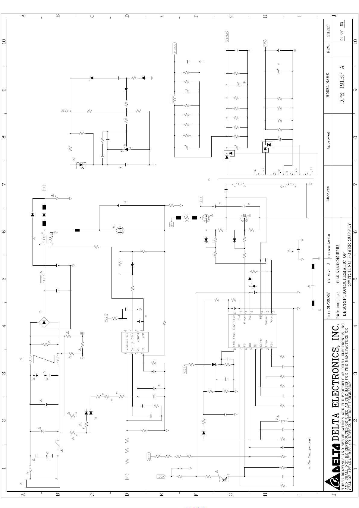
ZD370
32" POWER
R370
R378
R379
IC304
1/2
1
2
R377
C373
C374
C372
C141
C131
R374
D324
D320
L130
R375
R376
R372
IC370
C375
R130F
R130E
C132
R130D
R130C
R130B
R130A
C130
R140F
C142
R140E
R140D
R140C
R140B
R140A
C140
D140
D150
C151
C152
R150D
R150C
R150B
R150A
C150
P801
T601
C605
C819
C801
D801
D800
Q800
FB800
L800
C2
L3
C1
BD1
R3
R1
FL2
CY4
CY3
CX1
Z1
CY2
CY1
F1
R4
R5
R8
R6
NTC1
R809
R807
R818
IC801
R815
D803
R7
R812
R817
R817C
R817A
R805
D802
R808
C816
C808
C805
C806
R815A
R817B
R819
C803
C807
C804
R814
R810
R619
R801
C617
R614
R631
R632D604
R618 R606
R605
C604
R610
Q601Q602
R601
R635
D601
R602
C613
IC601
Q603
R628
R623
C610
R629
R630
C611
D602
C612
C618
R604
R636
R603
D605
R617 R627
1/2 IC304
C614
R626
ZD602
C608
T600
CY7
FB904
CY9
FB903
R615
C606
R613
R612
C607
R611
T600
C603
R609
C602
R608
R616
C601
R607
Page 62

32" POWER
R259
ZD251
R258
D252
C252
T901
Q202
D251
R215
IC251
IC904
R256
R255
R252
C251
R214
D201
R257
Q252
R253
R251
C953
C952
R956
R952
C955
R951
1/2
IC905
1
2
L900
FB901
D951
FB902
C917
C951
C954
R953
R955
R954
IC953
R213
R210
IC201
R254
Q251
Q203
R920
R941
R201
Q201
R203
R212
C203
R209
C202
R205
C201
R202
ZD252
P803
P802
D901
R903 D911
C923
IC901
R901
R904
R914
D910
Q904
IC904
1/2
IC905
R208
C916
R927
C913
R926
1/2
R207
R206
R204
R211
ZD906
D202
Page 63

24V
L10D
L10D
LP2
1.6U
LP2
1.6U
CP1
104
C0805
CP1
104
C0805
24Vaud
RP4
7.5K
R1206
RP4
7.5K
1
R1206
RP3
7.5K
R1206
RP3
7.5K
R1206
CSE1
CE-8D
270U/35V/KZH
CSE1
CE-8D
270U/35V/KZH
+
+
L7.5D
L7.5D
LP1
1.3U
LP1
1.3U
42" POWER
24V1
TO220INF-A
TO220INF-A
DP1
FCH20B10
DP1
FCH20B10
123
CP4
104
CP4
104
CSE4
270U/35V/KZH
CSE4
270U/35V/KZH
+
+
RP13
7.5K
RP13
7.5K
RP10
7.5K
RP10
7.5K
RP9
7.5K
RP9
7.5K
RP8
7.5K
RP8
7.5K
CSE7
CSE7
+
+
CSE3
CSE3
+
+
CSE2
CSE2
+
+
C0805
C0805
CE-8D
CE-8D
R1206
R1206
R1206
R1206
R1206
R1206
R1206
R1206
1000U/35V/KY
CE-12.5D
1000U/35V/KY
CE-12.5D
1000U/35V/KY
CE-12.5D
1000U/35V/KY
CE-12.5D
CE-12.5D
CE-12.5D
1000U/35V/KY
1000U/35V/KY
123
DP5
DP5
LP3
LP3
FCH20B10
TO220INF-A
FCH20B10
TO220INF-A
A1
A1
A1
of
of
CP11
C0805
CP11
C0805
104
104
12V
CSE5
CE-8D
270U/35V/KZH
CSE5
CE-8D
270U/35V/KZH
+
+
L7.5D
L7.5D
1.3U
1.3U
RP55
NC
R1206
RP55
NC
R1206
RP54
NC
R1206
RP54
NC
R1206
RP53
NC
R1206
RP53
NC
R1206
RP52
NC
R1206
RP52
NC
R1206
RP21
NC
R1206
RP21
NC
R1206
CE-10D
CE-10D
12V1
CSE6
470U/25V/KZE
CSE6
470U/25V/KZE
+
+
DP4
FCQS20A045
TO220INF-A
DP4
FCQS20A045
TO220INF-A
123
of
11
11
11
Power Schemtic
Power Schemtic
Power Schemtic
B132-001
B132-001
B132-001
Custom
Custom
Custom
Title
Size Document Number Rev
Date: Sheet
Title
Size Document Number Rev
Date: Sheet
Title
Size Document Number Rev
Date: Sheet
1
2
3
4
5
R0805
R0805
RP2
39
RP2
B+
1ohm/6A
1ohm/6A
STTH8L06FP
STTH8L06FP
L201
QP3325
L201
QP3325
BEAD WIRE
BEAD WIRE
140UH
140UH
DB-5S
DB-5S
BD1
D15XB60
BD1
D15XB60
t
t
B5
BEAD WIRE
B5
BEAD WIRE
B6
B6
BEAD WIRE
BEAD WIRE
DF2
DF2
R1206
R1206
10
10
VCC-PFC
2
1 8
1
4
RF7
RF7
R1206
R1206
RF1
RF1
BF10
BF10
BF10
BF10
SOD323
BAS316
SOD323
BAS316
!
CF7
CF7
CFE1
CFE1
+
+
213
510K
510K
C7.5D14
C7.5D14
472/1KV
472/1KV
CE-18X45A
CE-18X45A
150uF/450V
150uF/450V
QF3
QF3
RF21
RF21
22
22
R1206
R1206
QF1
QF1
5
3 910 6
RF2
RF2
C12
472/1KV
C12
472/1KV
C8
474/500V
C8
474/500V
C10
474/500V
C10
474/500V
C9
105/450V
C9
105/450V
3
!
R1206
R1206
RF14
RF14
3569
TO220AB-A
3569
TO220AB-A
R1206
R1206
33
33
RF8
RF8
SOT23
SOT23
PBSS4160T
PBSS4160T
510K
R1206
510K
R1206
C7.5D14
C7.5D14
CM-8X18.5
CM-8X18.5
CM-8X18.5
CM-8X18.5
CM-6X17
CM-6X17
39
360K
360K
10K
10K
RF12
RF12
213
RF5
RF5
RF3
RF3
R1206
R1206
C10
C10
CY2
CY2
12V 24V GENERATOR CIRCUIT
TR8MM-B
TR8MM-B
TR1
TR1
DF1
DF1
TO220-2
TO220-2
D20
D20
D203
1N5406
D203
1N5406
T-QP33
T-QP33
BF10
BF10
B2
B2
L11X22-2P
L11X22-2P
L4
L4
2
EMI CIRCUIT
C10
C10
CY1
CY1
D D
B14
BEAD
B14
BEAD
RF15
RF15
QF4
QF4
213
SOD323
BAS316
SOD323
BAS316
DF3
DF3
R1206
R1206
22
22
RF22
RF22
2
1
RF6
RF6
68K
R1206
68K
R1206
510K
R1206
510K
R1206
R1206
R1206
RF23
510K
RF23
510K
R0805
R0805
RF4
13K
RF4
13K
B13
B13
102/250V
102/250V
B11
B11
B10
B10
102/250V
102/250V
B12
B12
!
BF10
BF10
CP3
CP3
CP2
CP2
VCC-SYS
R1206
R1206
360K
360K
3569
TO220AB-A
3569
TO220AB-A
33
33
RF9
RF9
3
47
R1206
47
R1206
D15
D15
D2
D2
BF10
BEAD
BF10
BEAD
!
BEAD
BEAD
BEAD
BEAD
!
BF15
BEAD
BF15
BEAD
111312
225/10V
C0805
225/10V
C0805
RP11
RP11
225/10V
C0805
225/10V
C0805
RP6
5.1K
RP6
5.1K
R1206
R1206
RP7
RP7
RF16
RF16
10K
10K
R1206
R1206
RF11
RF11
R1206
R1206
QF2
QF2
PBSS5160T
PBSS5160T
7
GATE
ZCD5MULT3GND6VCC
UF1
UF1
C0805
C0805
CF1
471/50V
CF1
471/50V
AC-DETECT
PR1007G
PR1007G
1
BF10
BF10
3
BF10
BF10
SOD323
SOD323
DP2
BAS316
DP2
BAS316
R1206
R1206
RP15
10
RP15
10
R0805
R0805
1M
1M
R1206
R1206
R1206
R1206
300KF
300KF
R1206
R1206
360K
360K
!
510
510
RF10
RF10
SOT23
SOT23
4
1
CS
INV
D15
D15
D4
D4
L13X23
L13X23
LF1
LF1
!
QP1
FIB11N50A
TO220AB-A
QP1
FIB11N50A
TO220AB-A
213
RP19
RP19
R1206
R1206
RP18
RP18
C1206
C1206
CP7
104
CP7
104
16
VBOOT
UP1
UP1
CSS1DELAY2CF3RFmin4STBY5ISEN6LINE7DIS
C0805
C0805
C0805
C0805
CP5
474
CP5
474
CP6
CP6
CP8
472
CP8
472
10
10
RP12
RP12
RP17
100KF
RP17
100KF
R1206
R1206
RF17
330K
RF17
330K
RF13
0.05/3W
R5WP9.6
RF13
0.05/3W
R5WP9.6
R1206
R1206
C0805
C0805
CF6
56P/50V
CF6
56P/50V
2
COMP
L6562A
SO8-300
L6562A
SO8-300
8
CFE3
CFE3
+
+
CF2
CF2
VCC-PFC
BD+
PR1007G
PR1007G
B18
B18
!
6mH
6mH
4
2
B17
B17
!
B16
B16
!
B19
B19
978
T1
EER35
T-EER35
T1
EER35
B15
B15
VCC-SYS
13
NC
47
47
RP20
RP20
471
471
471
471
T-EER35
253
CP13
0.022U
CM-11.5X18
CP13
0.022U
CM-11.5X18
QP2
TO220AB-A
QP2
TO220AB-A
FIB11N50A
FIB11N50A
RP35
200F
R1206
RP35
200F
9
8
PFC_STOP
L6599D
L6599D
RP26
RP26
RP29
RP29
SO16-340
SO16-340
R1206
CP18
68P/1KV
C5
CP18
68P/1KV
C5
10K
R1206
10K
R1206
DP8
BAS316
SOD323
DP8
BAS316
SOD323
47
R1206
47
R1206
RP34
NC
R0805
RP34
NC
R0805
CP17
NC
C0805
CP17
NC
C0805
DP7
BAS316
SOD323
DP7
BAS316
SOD323
R0805
R0805
RP32
0
RP32
0
RP33
210
R0805
RP33
210
R0805
RP36
R0805
RP36
R0805
NC
NC
24V1
CP16
104
C0805
CP16
104
C0805
BF15
BEAD
BF15
BEAD
213
SOD323
SOD323
DP3
BAS316
DP3
BAS316
R1206
R1206
RP23
10
RP23
10
CP9
104
C0805
CP9
104
C0805
CP10
104
C0805
CP10
104
C0805
11
12
10
LVG
VCC
GND
R0805
R0805
R0805
R0805
RF18
9.1K
RF18
9.1K
RP37
RP37
CP25
C1206
NC
CP25
C1206
NC
RP45
20KF
R1206
RP45
20KF
R1206
8.25KF
R0805
8.25KF
R0805
RP51
1.13KF
R0805
RP51
1.13KF
R0805
RP44
RP44
12V 24V
CP24
CP24
NC
C0805
NC
C0805
100KF
R0805
100KF
R0805
RP50
RP50
CP27
104
C0805
CP27
104
C0805
C0805
C0805
R0805
R0805
CP22
NC
CP22
NC
RP47
0
RP47
0
NC
R1206
NC
R1206
RP56
RP56
1.5KF
R1206
1.5KF
R1206
RP42
RP42
8.2KF
R1206
8.2KF
R1206
!
RP38
5.1K
RP38
5.1K
1
UP4
AP431VLA
TO92-A
UP4
AP431VLA
RP43
NC
RP43
NC
1
UP3
UP3
4
CP21
102
CP21
102
R0805
R0805
RP41
13K
RP41
13K
TO92-A
R1206
R1206
2 3
+
+
23
CE-5D
CE-5D
CPE1
CPE1
10uF/50V
10uF/50V
LTV-817
DIP4
LTV-817
DIP4
C0805
C0805
R0805
R0805
CS3
CS3
R1206
R1206
R1206
R1206
R1206
R1206
R1206
R1206
CS2
CS2
100F
100F
100F
100F
100F
100F
RS2
RS2
RS1
RS1
RS5
RS5
R1W
R1W
RS30
100K/2W
RS30
100K/2W
CS1
CX-4.5X7.2
471/1KV
CS1
CX-4.5X7.2
471/1KV
12
D10
D10
ZDS6
ZDS6
P6KE200A
P6KE200A
5VS GENERATOR Circuit
C7.5D14
C7.5D14
CS15
CS15
472/1KV
472/1KV
B9
B9
BF10
BEAD WIRE
BF10
BEAD WIRE
B+
C0805
C0805
R0805
RF19
RF19
R0805
105/25V
105/25V
30K
30K
CF5
CF5
CF3
104/50V
C0805
CF3
104/50V
C0805
SOT23
SOT23
QT2
QT2
2 3
PMBT2907A
PMBT2907A
R1206
R1206
RT6
330F
RT6
330F
24Vaud
RT5
RT5
R1206
R1206
330F
330F
12V
RT4
RT4
330F
330F
R1206
R1206
RT3
RT3
R1206
R1206
330F
330F
1
RT2
1KF
R0805
RT2
1KF
R0805
5V
VCC
VCC-PFC
DT2
BAS316
SOD323
DT2
BAS316
SOD323
RT17
R0805
NC
RT17
R0805
NC
2
ZDT4
PDZ18B
SOD323
ZDT4
PDZ18B
SOD323
1
RT15
RT15
1
1 2
1KF
R1206
1KF
R1206
ZDT1
PDZ15B
SOD323
ZDT1
PDZ15B
SOD323
1 2
CT1
105/25V
C1206
CT1
105/25V
C1206
RT1
1KF
R1206
RT1
1KF
R1206
SOT23
SOT23
3
QT5
PMBT2222A
QT5
B4
B4
BF10
BEAD WIRE
BF10
BEAD WIRE
BEAD WIRE
BEAD WIRE
BEAD WIRE
6mH
6mH
2
4
BEAD WIRE
BF10
BF10
C10
C10
C10
C10
!
!
CY6
471/250V
CY6
471/250V
BF10
BF10
B3
BF10
BEAD WIRE
B3
BF10
BEAD WIRE
CY8
471
C10
CY8
471
C10
R1W
R1W
474
474
CX-11X17.5
CX-11X17.5
LF3
0.9mH
LF3
0.9mH
4
3
RX1
1.3M
RX1
1.3M
!
VZ1
14471
C7.5D14
VZ1
14471
CX2
CX2
!
C7.5D14
1
2
!
! !
471
C10
471
C10
CY7
CY7
C C
B7
B7
CY9
471/250V
CY9
471/250V
B8
B8
L13X23
L13X23
C10
C10
LF2
LF2
3
1
!
C10
C10
PMBT2222A
VCC-SYS
SOD323
SOD323
RT16
R0805
NC
RT16
R0805
NC
DT1
BAS316
DT1
BAS316
PWR ON/OFF CONTROL CIRCUIT
2
SOT23
SOT23
3
QT1
PMBT2222A
QT1
PMBT2222A
3
1
P801
P801
CON3P-AC
HD-03-P3.96-3
CON3P-AC
HD-03-P3.96-3
2
2 4
1 3
!
F1
T6.3AH/250V
FUSE5X20-HOLD
F1
T6.3AH/250V
FUSE5X20-HOLD
P802
P802
102/50V
102/50V
102/50V
102/50V
100F
100F
RS4
RS4
QT3
QT3
HD-16-P2A
HD-16-P2-1
HD-16-P2A
HD-16-P2-1
LS1
LS1
5V1
C1206
C1206
C1206
C1206
DS2
DS2
!
B1
BF10
BEAD WIRE
B1
BF10
BEAD WIRE
CS14
CS14
ZDT3
ZDT3
ZDT2
ZDT2
RT7
680F
RT7
680F
RT8
RT8
CT2
CT2
23
PMBT2907A
PMBT2907A
Pin2:GND 24Vaud
Pin4:24Vaud
Pin1:GND 24Vaud
Pin3:24Vaud
123456789
24Vaud
5V
L7.5D
1.3U
L7.5D
1.3U
D20
D20
SB540
SB540
1 694
DS1
PR1007G
DS1
PR1007G
C5
C5
NC
NC
SOD323
SOD323
RT9
RT9
PDZ27B
PDZ27B
1 2
1 2
PDZ13B
SOD323
PDZ13B
SOD323
R1206
R1206
10KF
R1206
10KF
R1206
104/50V
C0805
104/50V
C0805
1
SOT23
SOT23
B B
Pin10:5V
Pin12:5V
Pin6:GND 12V&5V
Pin8:12V
Pin9:12V
Pin11:5V
Pin5:GND 12V&5V
Pin7:GND 12V&5V
10111213141516
5V
12V
C0805
104/50V
C0805
104/50V
CS4
CS4
RS7
R1206
NC
RS7
R1206
NC
RS6
R1206
NC
RS6
R1206
NC
+
+
CSE10
CE-6.3D
476/50V KY
CSE10
CE-6.3D
476/50V KY
+
+
CE-10D
CE-10D
CSE8
1000U/25V KZH
CSE8
1000U/25V KZH
1078
2
OVP
RS8
RS8
D10
D10
D10
D10
RS9
68
RS9
68
!
8
7
DRAIN
GND1VDD2FB4CONT
US1
US1
RS27
RS27
DS4
BAS316
DS4
BAS316
R0805
R0805
R1206
R1206
1KF
1KF
RT12
30KF
RT12
30KF
CT3
104/50V
CT3
104/50V
UT1
BT169D
TO92
UT1
BT169D
TO92
2KF
2KF
RT11
RT11
1
!
4
RT10
3.3KF
R1206
RT10
3.3KF
R1206
UT2
UT2
Pin16:INV On/Off
Pin14:ACD
Pin13:Power On/Off
Pin15:DIM
ACD
PWR_ON
TS1
EE19
T-EE19-2
TS1
EE19
T-EE19-2
5
R1206
4.7
R1206
4.7
CSE11
CSE11
DS3
PR1007G
DS3
PR1007G
CE-5D
226/50V
CE-5D
226/50V
+
+
R1206
R1206
VDD
6
5
NC
EPT
DRAIN
3
VDD
RS10
RS10
R0805
200KF
R0805
200KF
SOD323
SOD323
OVP
R0805
R0805
C0805
C0805
RT13
RT13
R1206
R1206
3
23
LTV-817
DIP4
LTV-817
DIP4
R1206
R1206
RS11
0
RS11
0
CS8
CS8
CS7
CS7
VIPER28H
DIP8
VIPER28H
DIP8
R1206
30K
R1206
30K
BD+
PWR_ON
4.7KF
4.7KF
1
Pin2:24V
Pin4:24V
Pin1:24V
Pin3:24V
123456789
24V
5V1
VCC
+
+
SOD323
SOD323
ZDS1
PDZ18B
ZDS1
PDZ18B
1 2
C0805
104/50V
C0805
104/50V
C0805
C0805
104/50V
104/50V
RT14
100KF
RT14
100KF
CT4
104/50V
CT4
104/50V
2
Q4
Q4
2N7002K
2N7002K
Pin6:GND
Pin5:24V
CSE12
CSE12
DS5
DS5
RS12
RS12
R0805
R0805
C0805
C0805
SOT23
SOT23
Pin8:GND
Pin7:GND
CE-5D
226/50V
CE-5D
226/50V
D10
PR1007G
D10
PR1007G
SOD323
SOD323
R1206
510KF
R1206
510KF
Pin10:GND
Pin9:GND
5V
Pin12:INV On/Off
Pin14:NC
Pin11:NC
Pin13:DIM
1011121314
RS14
RS14
RS13
RS13
!
DS6
BAS316
DS6
BAS316
3.3MF
3.3MF
RS16
RS16
RS15
R1206
510KF
RS15
R1206
510KF
AC-DETECT
P803
P803
C0805
C0805
R1206
2.2KF
R1206
2.2KF
R1206
150F
R1206
150F
US2
US2
R0805
R0805
RS18
510KF
RS18
510KF
5V
R1206
R1206
R3
R3
HD-14-P2A
HD-14-P2R-2
HD-14-P2A
HD-14-P2R-2
J1
JUMP
JUMP
J1
JUMP
JUMP
RS28
R0805
NC
RS28
R0805
NC
RS21
R0805
6.2KF
RS21
R0805
6.2KF
RS25
6.2KF
RS25
6.2KF
R0805
R0805
RS20
1KF
RS20
1KF
RS24
200KF
RS24
200KF
CS10
474/50V
CS10
474/50V
C0805
C0805
CS11
222/50V
CS11
222/50V
1
2 3
1
23
US3
TO92-A
AP431VLA
US3
TO92-A
AP431VLA
DIP4
LTV-817
DIP4
LTV-817
4
ZDS3
NC
D10
ZDS3
NC
D10
1 2
SOD323
PDZ15B
SOD323
PDZ15B
ZDS2
ZDS2
1 2
CS9
C0805
103/50V
CS9
C0805
103/50V
2
3
1
RS22
RS22
QS1
SOT23
2N7002K
QS1
SOT23
2N7002K
2
3
1
SOT23
SOT23
RS17
R0805
1MF
RS17
R0805
1MF
QS2
2N7002K
QS2
2N7002K
R0805
NC
R0805
NC
RS29
RS29
SOD323
SOD323
12
ZDS4
ZDS4
PDZ-11B
PDZ-11B
CS13
CS13
RS19
R1206
510KF
RS19
R1206
510KF
R1206
R1206
RS23
RS23
ACD
R2
R1206
2KF
R2
R1206
2KF
3
SOD323
SOD323
D6
BAS316
D6
BAS316
R1
R1206
100KF
R1
R1206
100KF
VCC
R5
R5
AC- DETECT CIRCUIT
Q4_3
SOD323
SOD323
D7
BAS316
D7
BAS316
R1206
R1206
R1206
R1206
R6
1MF
R6
1MF
1MF
1MF
R4
1MF
R4
1MF
R0805
R0805
R0805
R0805
R0805
1MF
R0805
1MF
RS26
RS26
R0805
220K
R0805
220K
SOD323
SOD323
ZDS5
ZDS5
PDZ-11B
PDZ-11B
1 2
CS12
C0805
474/50V
CS12
C0805
474/50V
474
C0805
474
C0805
R0805
910KF
R0805
910KF
AC INPUT BROWN-OUT CIRCUIT
2
1
Q1
SOT23
2N7002K
Q1
SOT23
2N7002K
C2
C1206
105/50V
C2
C1206
105/50V
R10
R0805
NC
R10
R0805
NC
U1
DIP4
LTV-817
U1
DIP4
LTV-817
4
!
Q3
SOT23
2N7002K
Q3
SOT23
2N7002K
2
3
1
2 3
R7
R7
1
R1206
1KF
R1206
1KF
C6
C0805
NC
C6
C0805
NC
Q4_3
C5
NC
C5
NC
C0805
R1206
100KF
R1206
100KF
R0805
R0805
R14
NC
R14
NC
Q2
NC
Q2
NC
3
ZD1
PDZ-13B
ZD1
PDZ-13B
R8
R0805
7.5M
R8
R0805
7.5M
R16
R0805
NC
R16
R0805
NC
R9
R1206
1MF
R9
R1206
1MF
C0805
R0805
R0805
R15
100KF
R15
100KF
R13
R0805
100KF
R13
R0805
100KF
12
SOD323
SOD323
ZD3
PDZ-5.1B
ZD3
PDZ-5.1B
U10
AP431R
SOT23
U10
AP431R
SOT23
3 2
1
SOT23
SOT23
2
C7
223/25V
C0805
C7
223/25V
C0805
1
R12
R1206
220KF
R12
R1206
220KF
CX-4.5X7.2
CX-4.5X7.2
C4
334/63V
C4
334/63V
1 2
12
ZD2
ZD2
SOD323
SOD323
PDZ-13B
PDZ-13B
SOD323
SOD323
R0805
NC
R0805
NC
R18
R18
R17
R0805
NC
R17
R0805
NC
R11
R0805
4.3M
R11
R0805
4.3M
C3
C3
CX-4.5X7.2
CX-4.5X7.2
334/63V
334/63V
A A
2
3
4
5
6
10K
10K
R1206
R1206
47
47
15
OUT14HVG
391
391
C0805
C0805
R1206
R1206
22uF/50V
CE-5D
22uF/50V
CE-5D
104/50V
C0805
104/50V
C0805
BF15
BF15
BEAD
BEAD
CY4
CY4
BF10
BF10
BEAD
BEAD
BF10
BF10
BEAD
BEAD
CY3
CY3
BF10
BF10
BEAD
BEAD
Page 64

APPENDIX-A: Main assembly
LCD-19E30 Version:01
REF.No. PARTS No. DESCRIPION Q'TY REMARK
1 CLAPSA191A10I FRONT CABINET 1
2 CLCG10032V01I SPK SET (SSA19I) 2
3 CL454C0V30L01 IR PCB ASS’Y 1
4 CLAC6VT1800R1 LCD MODU 1 M185XW01(V0)-CC 18.5"A T
5 CLAPSA192410I KEY PLATE PCB ASS’Y 1
6 CL461C1930L02 MAIN PCB ASS’Y 1
7 CLAPSA191B00I BACK COVER ASSY 1
8 CLAPSA192C00I NECK ASSY 1
9 CLAPSA191D00I BASE ASSY GLOSSY 1
10 CL453C0830L21 POWER PCB ASS'Y 1
11 CLPK11V01170I REMOTE CTRL 1
12 CLHDJKTA1930I USER'S MANUAL 1
13 CLFJSA191600I EPS FOAM(RIHGT) 1
14 CLFJSA191700I EPS FOAM(LEFT) 1
15 CLHK1TV19021I EPE BAG for unit 1
16 CLHB2SA19030I CARTON 1
17 CLHK3SA19020I PE BAG-STAND 1
CLGA02003010I PWR CORD(S) (BLK) 1 EU Type
18
CLGA04003010I PWR CORD(S)SR127BLK125BA 1 UK Type
Page 65

6
9
8
7
1
5
4
10
3
2
LCD-19E30 Assembly
Page 66

LCD-26E30 Version:01
REF.No. PARTS No. DESCRIPION Q’TY REMARK
1 CLAPSA260410I FRONT CABINET 1
2 CLCG10102V54I SPK SET (SSA32/42I) 2
3 CL454C0S30L01 IR PCB ASS’Y 1
CLAC6VT2600R2
4
CLAC6VT2600R4
(2nd source)
5 CLFASA421700I KEY PLATE PCB ASS’Y 1
6 CL461C1630L31 MAIN PCB ASS’Y 1
7 CLAPSA263A00I BACK COVER ASSY 1
8 CLAPSA320400I BASE ASSY GLOSSY 1
9 CLPK101V1090I POWER PCB ASS’Y 1
10 CLPK11V01170I REMOTE CTRL 1
11 CLHDJKTA1930I USER’S MANUAL 1
12 CLFJSA260700I EPS FORM(TOP RIGHT) 1
13 CLFJSA260800I EPS FORM(BOTTTOM LIFT) 1
14 CLFJSA260900I
15 CLHK1LV26001I EPE BAG for unit 1
16 CLHB4SA26030I CARTON 1
17 CLHK3OL77801I
18 CLHK3TW26000I PE BAG-STAND 1
LCD MODU
EPS FORM(BOTTOM RIGHT)
ZIPPERED BAG
for accessories
1 T260XW02(VQ)-RR 26”A+ T
T260XW02(VQ)-CR 26”A+ T
1
1
1
CLGA02003010I PWR CORD(S) (BLK) 1 EU Type
19
CLGA04003010I PWR CORD(S)SR127BLK125BA 1 UK Type
Page 67

5
8
7
6
1
4
9
3
LCD-26E30 Assembly
2
Page 68

LCD-32E30 Version:01
REF.No. PARTS No. DESCRIPION Q’TY REMARK
1 CLAPSA320110I FRONT CABINET 1
2 CL454C0S30L01 IR PCB ASS’Y 1
3 CLCG10102V54I SPK SET (SSA32/42I) 2
CLAC6VT3200R1 1 T315XW02(VS)-RR 32”A+ T
4
CLAC6VT3200R2
(2nd source)
5 CLFASA421700I KEY PLATE PCB ASS’Y 1
LCD MODU
T315XW02(VS)-CR 32”A+ T
1
6 CL461C1630L01 MAIN PCB ASS’Y 1
7 CLAPSA320800I BACK COVER ASSY 1
8 CLAPSA320400I BASE ASSY GLOSSY 1
CLPK101V1100I
9
CLPK101V1180I
(2nd source)
10 CLPK11V01170I REMOTE CTRL 1
11 CLHDJKTA1930I USER’S MANUAL 1
12 CLFJSA321A00I EPS FORM(TOP LIFT) 1
13 CLFJSA321B00I EPS FORM(TOP RIGHT) 1
14 CLFJSA321C00I EPS FORM(BOTTTOM LIFT) 1
15 CLFJSA321D00I EPS FORM(BOTTOM RIGHT) 1
16 CLHK1LV32D12I EPE BAG for unit 1
17 CLHB4SA32030I CARTON 1
18 CLHK3OL77801I
19 CLHK3TW26000I PE BAG-STAND 1
POWER PCB ASS’Y 1
ZIPPERED BAG
for accessories
1
CLGA02003010I PWR CORD(S) (BLK) 1 EU Type
20
CLGA04003010I PWR CORD(S)SR127BLK125BA 1 UK Type
Page 69

1
2
3
5
4
6
9
LCD-32E30 Assembly
7
8
Page 70

LCD-42E30 Version:01
REF.No. PARTS No. DESCRIPION Q'TY REMARK
1 CLAPSA420430I FRONT CABINET 1
2 CLCG10102V54I SPK SET (SSA32/42I) 2
3 CL454C0S30L01 IR PCB ASS’Y 1
4 CLAC6VG4205R1 LCD MODU 1 LC420WXN-SBA1 42"A G
5 CLFASA421700I KEY PLATE PCB ASS’Y 1
6 CL461C1630L12 MAIN PCB ASS’Y 1
7 CLAPSA420B00I BACK COVER ASSY 1
8 CLAPSA420500I BASE ASSY GLOSSY 1
CLPK101V1110I
9
CLPK101V1170I
(2nd source)
10 CLPK11V01170I REMOTE CTRL 1
11 CLHDJKTA1930I USER'S MANUAL 1
12 CLFJSA420700I EPS FORM(TOP LIFT) 1
13 CLFJSA420800I EPS FORM(TOP RIGHT) 1
14 CLFJSA420900I EPS FORM(BOTTTOM LIFT) 1
15 CLFJSA420A00I EPS FORM(BOTTOM RIGHT) 1
16 CLHK1SA42001I EPE BAG for unit 1
17 CLHB4SA42050I CARTON 1
18 CLHK3OL77801I
19 CLHK3TW37000I PE BAG-STAND 1
POWER PCB ASS'Y 1
ZIPPERED BAG
for accessories
1
CLGA02003010I PWR CORD(S) (BLK) 1 EU Type
20
CLGA04003010I PWR CORD(S)SR127BLK125BA 1 UK Type
Page 71

LCD-42E30F Version:01
REF.No. PARTS No. DESCRIPION Q'TY REMARK
1 CLAPSA420410I FRONT CABINET 1
2 CLCG10102V54I SPK SET (SSA32/42I) 2
3 CL454C0S30L01 IR PCB ASS’Y 1
4
CLAC6VG4204R3
5 CLFASA421700I KEY PLATE PCB ASS’Y 1
6 CL461C1630L11 MAIN PCB ASS’Y 1
7 CLAPSA420B00I BACK COVER ASSY 1
8 CLAPSA420500I BASE ASSY GLOSSY 1
CLPK101V1110I
9
CLPK101V1170I
(2nd source)
10 CLPK11V01170I REMOTE CTRL 1
11 CLHDJKTA1930I USER'S MANUAL 1
12 CLFJSA420700I EPS FORM(TOP LIFT) 1
13 CLFJSA420800I EPS FORM(TOP RIGHT) 1
14 CLFJSA420900I EPS FORM(BOTTTOM LIFT) 1
15 CLFJSA420A00I EPS FORM(BOTTOM RIGHT) 1
16 CLHK1SA42001I EPE BAG for unit 1
17 CLHB4SA42030I CARTON 1
18 CLHK3OL77801I
19 CLHK3TW37000I PE BAG-STAND 1
LCD MODU 1 LC420WUN-SBA1 42"A G
POWER PCB ASS'Y 1
ZIPPERED BAG
for accessories
1
CLGA02003010I PWR CORD(S) (BLK) 1 EU Type
20
CLGA04003010I PWR CORD(S)SR127BLK125BA 1 UK Type
Page 72

5
8
7
6
3
4
9
2
LCD-42E30/LCD-42E30F Assembly
1
Page 73

Removing or Installing the Stand
( 19”)
Cautions:
1. Carefully handle the unit during setup and consult authorized service personnel to ensure successful
installation.
2. Before performing work spread cushioning over the base area to lay the Display on. This will prevent
it from being damaged.
3. Disconnect the AC power cord firstly.
To remove the stand: (if will mounting)
1. Place the LCD TV screen facing down on a flat surface place where maintained with soft materials
(such as a blanket) for protecting the display screen.
2. Pull the stand base out from the cabinet after push 6 hooks.(A)
3. Screw driver remove screws from stand mounting inserts (B) before installing stand base. (For will mounting).
To install the stand
1. Place the LCD TV screen facing down on a flat surface place where maintained with soft materials
(such as a blanket) for protecting the display screen.
2. Secure the stand to the TV with 2 screws.
3. Pull the stand base.
Note
Ɣ
Do not remove the stand from the TV unless using an optional bracket to mount it.
Ɣ
The appearance of the unit may differ from the actual one.
Page 74

Removing or Installing the Stand
(26” / 32” / 42”)
Cautions:
1. Carefully handle the unit during setup and consult authorized service personnel to ensure successful
installation.
2. Before performing work spread cushioning over the base area to lay the Display on. This will prevent
it from being damaged.
3. Disconnect the AC power cord firstly.
To remove the stand: (if will mounting)
1. Place the LCD TV screen facing down on a flat surface place where maintained with soft materials
(such as a blanket) for protecting the display screen.
2. Release screw in 4 holes with screw driver.
To install the stand
1. Place the LCD TV screen facing down on a flat surface place where maintained with soft materials
(such as a blanket) for protecting the display screen.
2. Secure the stand to the TV with 4 screw.
Note
Ɣ
Do not remove the stand from the TV unless using an optional bracket to mount it.
Ɣ
The appearance of the unit may differ from the actual one.
Page 75

ME-ASIA SERVICE MANUAL CHANGE LIST
DATE Page VERSION CHANGE ITEM
24 /June 2009
Page 64 / 66 / 68 / 70
/ 71
01 Add power code on APPENDIX-A of each
models.
 Loading...