

Page 1
SERVICE MANUAL LCD Television
Specifications
Power Source . . . . Monitor: DC12V
AC Adapter: AC100
-
240V, 50Hz/60Hz (Output DC 12V)
Screen Size . . . . . . . . . .15 Inch (Measured Diagonally)
Picture Resolution . . . . .640 x 480=307,200 Pixels
Brightness . . . . . . . . . . .500 cd/m
2
Colour System . . . . . . . .PAL, SECAM, NTSC4.43, NTSC, PAL-60Hz
Television System . . . . .B/G, DK, K’, I, M/M
Channel Coverage . . . .VHF: E2-E12, R1-R12, K1-K9, A2-A13, J1-J12
0-11, 5A (Australia), 1-11 (New Zealand)
UHF: 21-69, A14-A69, J13-J62
28-69 (Australia)
CATV: S1-S41, X, Y, Z, Z+1, Z+2
Aerial Input Impedance 75Ω
Speaker . . . . . . . . . . 5 cm ✕ 9 cm ✕ 2 pcs.
Sound Output (RMS). ...2W + 2W
Input Terminals
AV1 (Video): Composite video Input
S-Video (Y/C Separate) DIN Jack Input
AV1 (Audio): L/R Stereo Input
AV2 or DVD (Video): Composite/Component Y, C
B, CR Input
AV2 or DVD (Audio): L/R Stereo Input
Output Terminals
Video Monitor Output x 1
Audio Monitor Output: L/R x 1
Headphone Jack: Mini Stereo Jack x 1
Dimensions . . . . . . . . . . 373 (W) ✕ 390 (H) ✕ 226 (D)mm (Included Stand)
Weight . . . . . . . . . . . . . . approx. 6.4 Kg (Included Stand)
Specifications subject to change without notice
N2JVZ
FILE NO.
Model No. LCD-15CA1Z
(Australia/Middle East/Asia)
Give complete “SERVICE REF. NO.” for parts
order or servicing. It is shown on the rating label
at the cabinet back of the unit.
This T.V. receiver will not work properly in
foreign countries where the television
transmission system and power source differ from the design specifications. Refer to
the specification table.
Product Code:111372516
REFERENCE NO. SM5110674
Original Version
Chassis Series: UB3-C
Service Ref. No. LCD-15CA1Z-00
Page 2

Contents
-2-
Safety Notice . . . . . . . . . . . . . . . . . . . . . . . . . . . . . . . . . . . . . . . . . . . . . 2
Chassis Block Diagram . . . . . . . . . . . . . . . . . . . . . . . . . . . . . . . . . . . . 3-4
IC Block Diagrams . . . . . . . . . . . . . . . . . . . . . . . . . . . . . . . . . . . . . . . . . 5
CPU Port Functions . . . . . . . . . . . . . . . . . . . . . . . . . . . . . . . . . . . . . . . . 6
Service Adjustments . . . . . . . . . . . . . . . . . . . . . . . . . . . . . . . . . . . . . . 7-8
On-screen Service Menu . . . . . . . . . . . . . . . . . . . . . . . . . . . . . . . . . . . . 8
Mechanical Disassembly . . . . . . . . . . . . . . . . . . . . . . . . . . . . . . . . . 9-11
Cabinet Parts List . . . . . . . . . . . . . . . . . . . . . . . . . . . . . . . . . . . . . . . . 12
Chassis Electrical Parts List . . . . . . . . . . . . . . . . . . . . . . . . . . . . . . .13-21
Safety Notice
Safety Precautions
The following precautions must be observed.
1: Comply with all caution and safety-related notes provided on the cabinet back, cabinet bottom, inside the
cabinet or on the chassis.
2: When replacing a chassis in the cabinet, always be certain that all the protective devices are installed
properly, such as, control knobs, adjustment covers or shields, barriers, etc..
DO NOT OPERATE THIS TELEVISION WITHOUT THE PROTECTIVE SHIELD IN POSITION AND PROPERLY
SECURED.
3: Before replacing the cabinet cover, thoroughly inspect the inside of the cabinet to see that no stray parts or
tools have been left inside.
Before returning any television to the customer, the service personnel must be sure that it is completely safe to
operate without danger of electrical shock.
Product Safety Notice
Product safety should be considered when a component replacement is made in any area of a receiver.
Components indicated by mark in the parts list and the schematic diagram designate components in which
safety can be of special significance. It is particularly recommended that only parts designated on the parts list
in this manual be used for component replacement designated by mark . No deviations from resistance
wattage or voltage ratings may be made for replacement items designated by mark .
Page 3
-3-
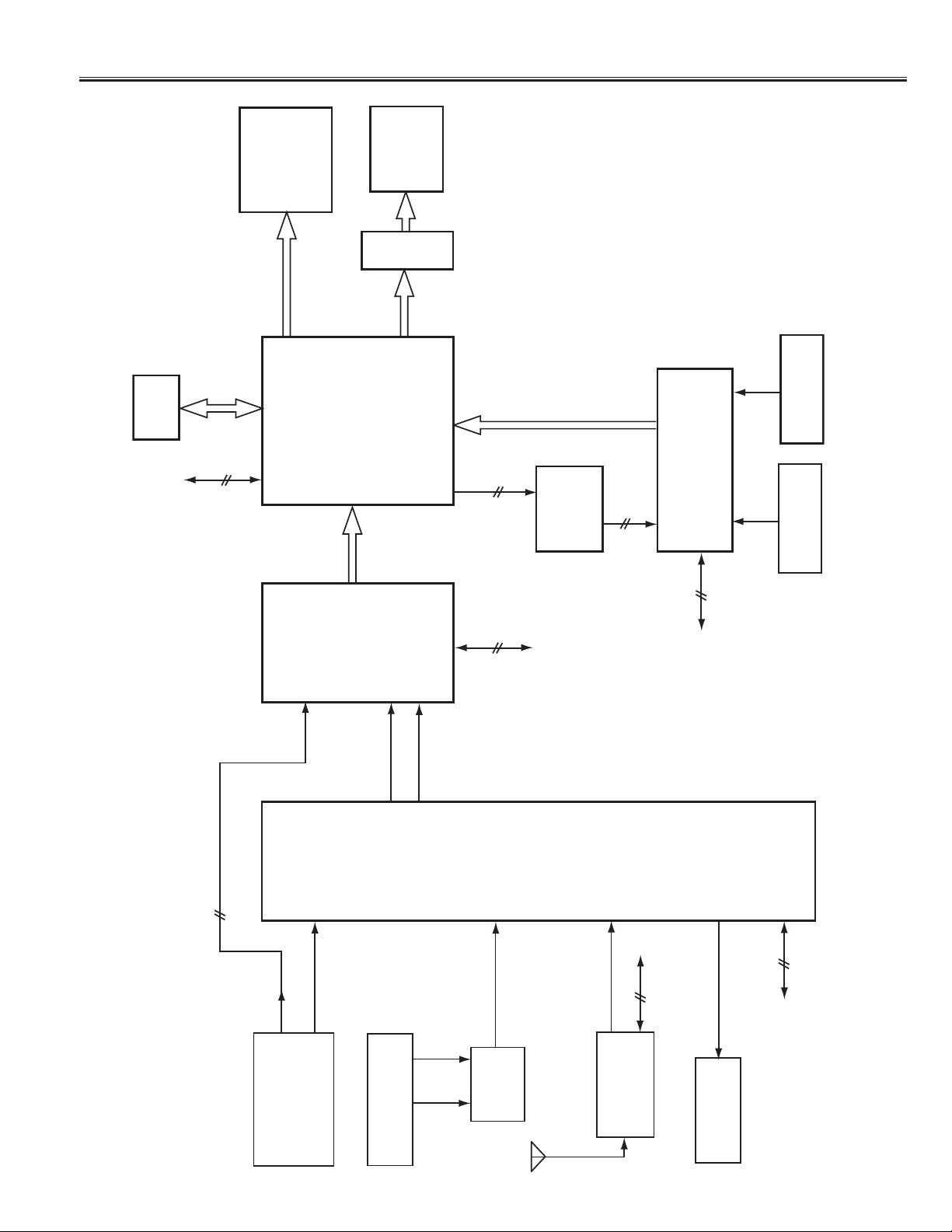
Chassis Block Diagrams
(Video Signal Lines)
IC702
SDRAM
(20V)
LCD PANEL
(For 20V)
(For 15V)
R/G/B (0-7)
IC701
(15V)
LCD PANEL
R/G/B (0-7)
IC801
TTL/LVDS
CONVERTER
OSD IN
152 151 150 144 149
R G B Y I
OSD_CC
OSD OUT
22 23 24 25 21
R G B Y I
RC INPUT
35
ASSY, PWB,
LED BOARD
I/P CONVERTER
CPU
SCREEN CONTROLLER
IIC BUS
(0-7)
Y/C DIGITAL
153
154
OSD_HD
OSD_VD
3
5
IC204
DC/DC
CONVERTER
4
OSD_VD
6
OSD_HD
IC201
27
26
IIC BUS
17
KEY INPUT
ASSY, PWB,
KEY BOARD
IC601
DIGITAL DECODER
ASSY, PWB MAIN
AV2 INPUT
WITH Y/C SEPARATON
Cb, Cr IN
IC301
SWITCHING IC
Cb, Cr
92/94
8
COMP. VIDEO/Y
AV1 I NPUT
Y IN
Y
IIC BUS
85
90
C IN
C
18
20
2
TV COMP. VIDEO
19
TU201
IIC BUS
4/5
TUNER
22
VIDEO MONITOR OUT
13/14
IIC BUS
VIDEO
COMP.
S-VIDEO
COMP. VIDEO or
S-VIDEO
3
IC303
1
4
7
VIDEO SW
VIDEO MONITOR
COMPOSITE VIDEO IN
COMPONENT VIDEO IN
COMPOSITE VIDEO IN
S-VIDEO IN
OUT
Page 4
-4-
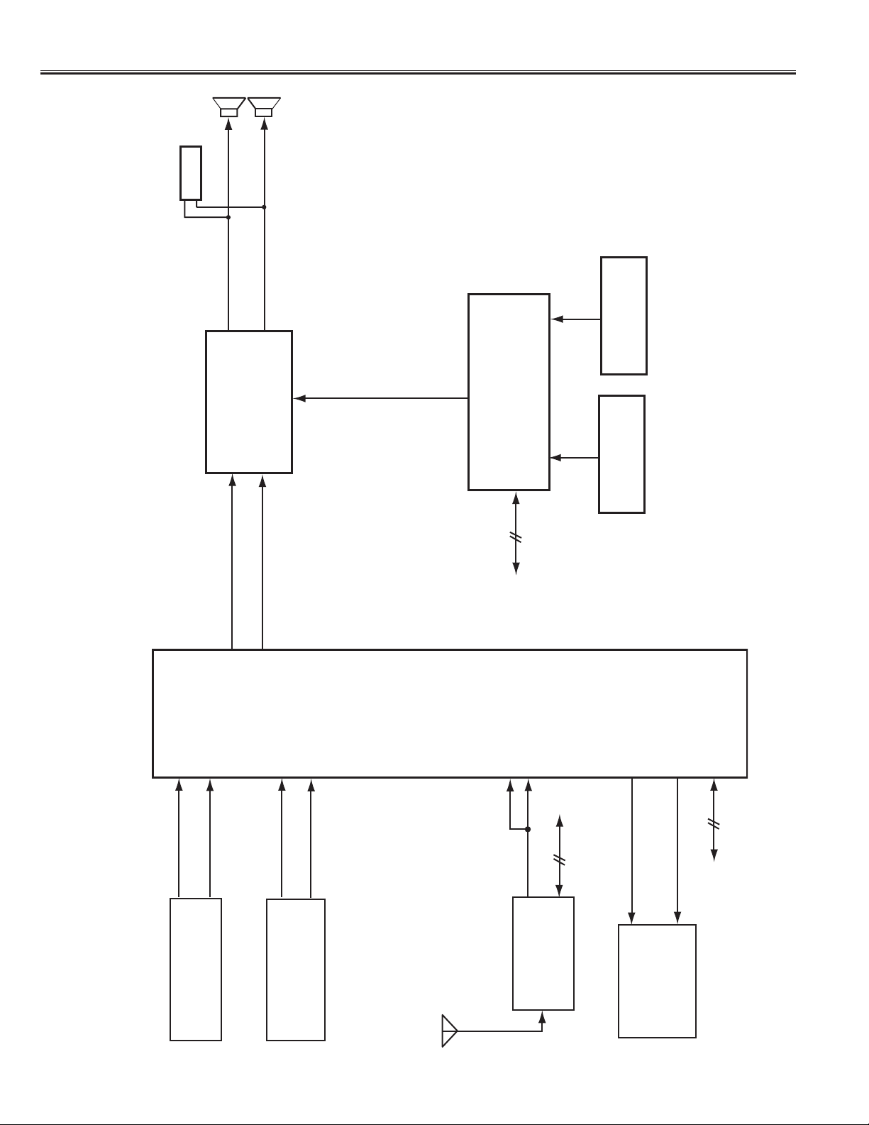
Chassis Block Diagrams
(Audio Signal Lines)
SP901
HEADPHONE
JACK
L-OUT
IC302
AUDIO AMP.
SP902
R-OUT
3
1
MUTE
5
8
10
3
CPU
IC201
35
17
RC INPUT
ASSY, PWB,
KEY INPUT
ASSY, PWB,
KEY BOARD
LED BOARD
ASSY, PWB MAIN
IC301
SWITCHING IC
AUDIO L (AV2)
IIC BUS
AUDIO L
AUDIO R
17
16
7
AUDIO L (AV1)
5
AUDIO R (AV1)
9
11
AUDIO R (AV2)
3
2
IIC BUS
AUDIO
16
4/5
23
(RIGHT)
AUDIO MONITOR OUT
24
(LEFT)
AUDIO MONITOR OUT
13/14
IIC BUS
AV2 INPUT
AV2 AUDIO IN
AV1 INPUT
AV1 AUDIO IN
TU201
TUNER
OUT
AUDIO MONITOR
Page 5
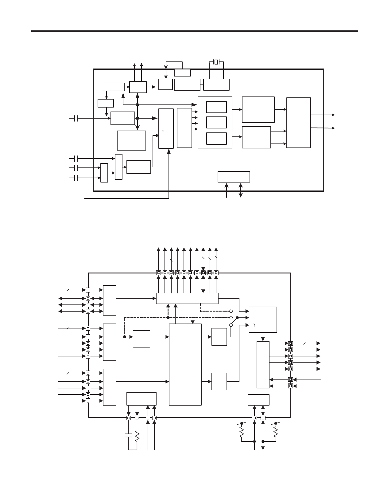
IC Block Diagrams
-5-
IC601 < Digital Decoder with 3D YC.> TC90A92AFG
IC701 < I/P Converter Screen Controller > TC6398AF
42M
X'tal
D/A
Clock
Gene.
4M
CVBS/Y
Sync Sep.
Clamp
10bit ADC
HD/VD
Timing
27 M
ID1
S/N detection
CCD slice
X 8
27M
4fsc
DRAM
C
Cb
Cr
MPX
SW
27M
8bit ADC
Digital I/F
reference
clock
3 line
comb
3D comb
Motion
Det.
SCL SDA
IIC-BUS
Vertical enhance
LTI
contrast adust
delay adjust
ACC
color decord
TINT adjust
Color adjust
ITU-R656
encode
656/601
Format
VIN3
(OSD)
VIN1
VIN2
Dat a 8bit
CLK
VD
HD
Data 24bit
CLK
VD
HD
FIELD
Data 16bit
CLK
VD
HD
FIELD
OSD
I/ F
IN 1
Video
I/ F
IN 2
Video
I/ F
RGB
RGB through mode
RGB
to
RGB
YCbCr
YCbCr
YCbCr
Clock Gen.
( P LL )
SDRAM(32 or 64Mbit)
CKE
CLK
YCbCr
DQM-4bit
CASN
WEN
S D R A M C
Color A djust.
H/ V Sc aling
IP- Conv .
H/ V Filter
Outline-
sharpening
RASN
CSN
DQ-32bit
BS-2bit
A-11bit
YCbCr
RGB
YCbCr
RGB
TC6398AF/ XB
Blending
Posit ioning
-correct .
to
LC D
to
I2C- I/ F
I/ F
Dat a 2 4 bit
ENAB
VD
HD
CLKO
CLKI
VO UT_DISP
TFT- LCD
AGS
LP
SYSCLK
RESETN
SDA
SCL
µ
-Com
Page 6

-6-
CPU Port Functions
Pin No. Function Name Function IN/OUT
1 VSS GND
-
2 BL-BRI FOR PANEL BACK LIGHT BRIGHTNESS OUT
3 PWM1 SOUND MUTE OUT
4 DISPLAY ON DISPLAY ON OUT
5POWER DOWN POWER DOWN OUT
6STAND-BY POWER ON/OFF OUT
7PANEL ON PANEL ON OUT
8
SCALER RESET SCALER RESET (RESET=LOW)
OUT
9VDATR RESET VDATR RESET OUT
10 BL-ON PANEL ON OUT
11 SCL1 IIC BUS PRT FOR EEPROM (SCL: CLOCK) I/O
12 SDA1 IIC BUS PRT FOR EEPROM (SDA: DATA) I/O
13 P53 PANEL OPTION (HIGH=15”, LOW=20”) IN
14 P54 BASS OUT
15 AFT AFT INPUT IN
16 SENSOR-IN P-FAIL2 (FAILURE=Less than 4V) IN
17 KEY KEY INPUT IN
18 MODE1 MODE1 OUT
19 MODE2 MODE2 OUT
20 SAW SW SAW SWITCH OUTPUT OUT
21 OSD-I OSD-I OUTPUT OUT
22 OSD-R OSD RED OUTPUT OUT
23 OSD-G OSD GREEN OUTPUT OUT
24 OSD-B OSD BLUE OUTPUT OUT
25 OSD-Y OSD BLANKING OUTPUT OUT
26 P70(HD) H-SYNC. IN IN
27 P71(VD) V-SYNC. IN IN
28 OSC1 CLOCK INPUT FOR OSD IN
29 OSC2 CLOCK OUTPUT FOR OSD OUT
30 TEST TEST PORT IN
31 XIN CLOCK INPUT FOR MAIN IN
32 XOUT CLOCK OUTPUT FOR MAIN OUT
33 RESET RESET PORT (RESET=LOW) IN
34 P-FAIL1 POWER FAILURE (FAILURE=LOW) IN
35 RMT RC INPUT IN
36 BVIREADY BVIREADY IN
37 SCL0 IIC BUS PORT FOR IC I/O
38 SDA0 IIC BUS PORT FOR IC I/O
39 GND GND --
40 FORMAT2 STATUS IN
41 FORMAT2 ACK IN
42 VDD VDD 5V --
Page 7
Service Adjustments
-7-
General
This set has an On-screen Service Menu system included in the CPU thar allows remote operation for most of
the service adjustments.
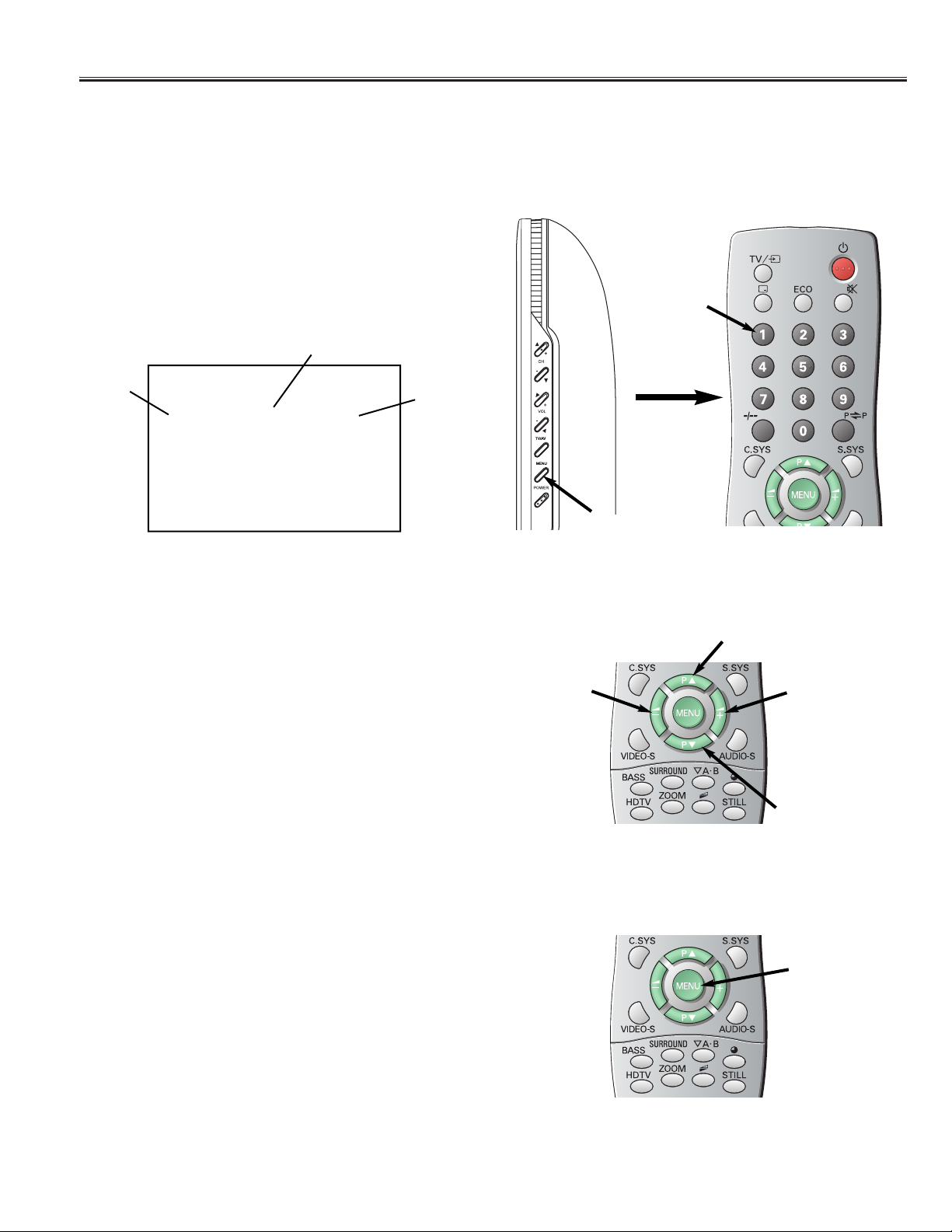
On-screen Service Menu System
1. Enter the Service Menu
While pressing the MENU button on the television, press the Number Key 1 on the remote control
unit. The Service Menu now appear.
2. Service Adjustments:
Press the POSITION UP or POSITION DOWN
button on the remote control handset to select the
desired service menu item you want to adjust.
When the POSITION UP is kept pressed, ten steps of
adjustment items will step up at a time.
When the POSITION DOWN is kept pressed, ten
steps of adjustment items will step down at a time.
Use the VOLUME + or
-
or number button to adjust
the data. The + or-button will increase or decrease
the data sequentially.
3. Exit from the Service Menu
Press the MENU button twice to turn off the Service
Menu display.
The data which is set in the service mode is stored
into the memory IC automatically.
SERVICE
001 PLUG PLAY 00
[ Service Mode Display ]
Title
Item No.
Adjustment
Data
MENU
1
[ Entering the Service Menu ]
VOLUME +
VOLUME
-
POSITION UP
POSITION DOWN
[ Service Adjustment ]
MENU
[ Exit from the Service Menu ]
Page 8
-8-
Important Notice:
Do not attempt to adjust service adjustments not listed
on above otherwise it may cause loss of performance
and for correct operation.
Service Adjustments
White Balance Adjustment
1. Receive a White Pattern.
2. Set the television to following conditions:
Brightness: Normal
Colour: Normal
Contrast: Maximum
3. Enter the Service Menu.
Adjustment Item:
142 WBGREEN
151 WBRED
160 WBBLUE
4. Decide the fixed item which is maximum value
(Example, Item 151 WBRED), select item of other 2
colours (Example, Item 142 WBGREEN or
Item 160 WBBLUE) with the POSITION UP or DOWN
button, and adjust a proper white balance with the
VOLUME + or
-
button.
After adjustment, confirm white balance again by
normal picture.
Note: Adjusted data is less than the fixed data.
5. Press the MENU button to turn off the Service Menu
display.
The data which is set in the service mode is stored
into the memory IC automatically.
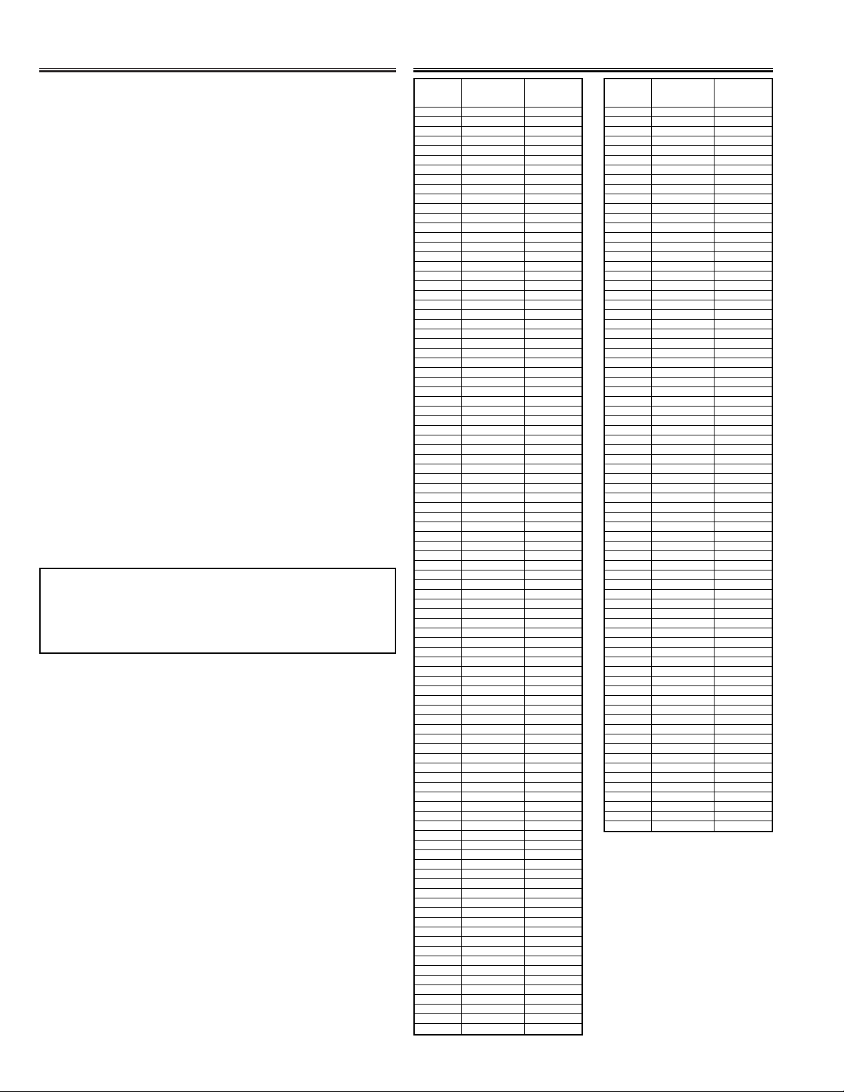
On-screen Service Menu
Item
TITLE
INITIAL
No. DATA
001 PLUG PLAY 00
002 TUNER SEL 00
003 IF1HSIZEL 00
004 IF1HSIZEH 80
005 IF1VSIZEL 00
006 IF1VSIZEH C0
007 IF1HSTAL 00
008 IF1HSTAH 26
009 IF1VSTAL 01
010 IF1VSTAH 08
011 NT HCUTSTAL 00
012 NT HCUTSTAH 07
013 NT VCUTSTAL 00
014 NT VCUTSTAH 05
015 NT HCUTSIZL 00
016 NT HCUTSIZH A7
017 NT VCUTSIZL 00
018 NT VCUTSIZH 79
019 IF2HSTAL 00
020 IF2HSTAH 00
021 IF2VSTAL 00
022 IF2VSTAH 00
023 IF2HCUTSTAL 00
024 IF2HCUTSTAH 0B
025 IF2VCUTSTAL 00
026 IF2VCUTSTAH 06
027 IF2HCUTSIZL 00
028 IF2HCUTSIZH A0
029 IF2VCUTSIZL 00
030 IF2VCUTSIZH 83
031 OSDHSIZEL 00
032 OSDHSIZEH B6
033 OSDVSIZEL 00
034 OSDVSIZEH 70
035 OSDPISEL 00
036 OSDHOFSTL 00
037 OSDHOFSTH 10
038 OSDVOFSTL 00
039 OSDVOFSTH 08
040 IP2MODEN 02
041 IP2MODE 02
042 FILTERSEL 00
043 FILH2YTAP1 00
044 FILH2YTAP2 00
045 FILH2YTAP3 87
046 FILH2YTAP4 87
047 FILH2YTAP5 5C
048 FILH2CTAP1 00
049 FILH2CTAP2 00
050 FILH2CTAP3 87
051 FILH2CTAP4 87
052 FILH2CTAP5 5C
053 FILV2YTAP1 85
054 FILV2YTAP2 10
055 FILV2YTAP3 2A
056 FILV2CTAP1 85
057 FILV2CTAP2 10
058 FILV2CTAP3 2A
059 FILH2ON 03
060 FILV2ON 03
061 EDG2ON 13
062 EDG2PLM 20
063 EDG2MLM 20
064 EDG2TAP 5A
065 LOHSIZEL 00
066 LOHSIZEH 64
067 LOVSIZEL 00
068 LOVSIZEH 78
069 EDG2LIM 06
070 EDG2BAI 10
071 LO1HSTAH 00
072 LO1VSTAL 00
073 LO1VSTAH 00
074 LO2ON 01
075 LO2HSTAL 00
076 LO2HSTAH 00
077 LO2VSTAL 00
078 LO2VSTAH 00
079 LRFLG1 00
080 LRFLG2 00
081 COLADJ1CONT 1B
082 COLADJ1BRIG 40
083 COLADJ1UFU C0
084 COLADJ1VFU 80
085 COLADJ1UFV 80
086 COLADJ1VFV C0
087 COLADJ2CONT 1B
088 COLADJ2BRIG 40
089 COLADJ2UFU C0
090 COLADJ2VFU 80
091 COLADJ2UFV 80
092 COLADJ2VFV C0
093 NT HSIZEL 00
094 NT HSIZEH 80
095 NT VSIZEL 00
096 NT VSIZEH C0
Item
TITLE
INITIAL
No. DATA
097 LO2HSIZEL 00
098 LO2HSIZEH 80
099 LO2VSIZEL 00
100 LO2VSIZEH C0
101 EXPMODE1 00
102 EXPMODE2 00
103 EXP1INA 28
104 EXP1INB 28
105 EXP1INC 28
106 EXP1IND 28
107 EXP1INE 28
108 EXP1OUTA 28
109 EXP1OUTB 28
110 EXP1OUTC 28
111 EXP1OUTD 28
112 EXP1OUTE 28
113 EXP2INA 18
114 EXP2INB 1B
115 EXP2INC 1E
116 EXP2IND 21
117 EXP2INE 38
118 EXP2OUTA 24
119 EXP2OUTB 24
120 EXP2OUTC 24
121 EXP2OUTD 24
122 EXP2OUTE 38
123 GAMWS 01
124 IF2CUTEN 01
125 VIDEOS1COL 23
126 VIDEOS1BRI 20
127 VIDEOS1CONT 3F
128 VIDEOS1SHP 16
129 VIDEOS2COL 1E
130 VIDEOS2BRI 24
131 VIDEOS2CONT 36
132 VIDEOS2SHP 08
133 VIDEOS3COL 12
134 VIDEOS3BRI 22
135 VIDEOS3CONT 1B
136 VIDEOS3SHP 03
137 NOR G 00
138 WARM G E8
139 COOL G F8
140 WBGREEN DIF 00
141 WBGREEN S 00
11 4422 WWBBGGRR EEEENN FF77
143 BBGREEN 02
144 BBGREEN DIF 00
145 BBGREEN S 00
146 NOR R 00
147 WARM R 00
148 COOL R F0
149 WBRED DIF 00
150 WBRED S 00
11 5511 WWBBRREEDD FF00
152 BBRED 00
153 BBRED DIF 00
154 BBRED S 00
155 NOR B 00
156 WARM B EA
157 COOL B 00
158 WBBLUE DIF 00
159 WBBLUE S 00
11 6600 WWBBBB LL UU EE FF FF
161 BBBLUE 02
162 BBBLUE DIF 00
163 BBBLUE S 00
164 GAMMA 07
165 WSVSTA 18
166 WSVSIZE D1
167 PERR 00
168 SOUND OPT 00
169 INDONESIA 00
170 YUV COLOR 02
171 YUV TINT 00
Page 9
Mechanical Disassembly
-9-
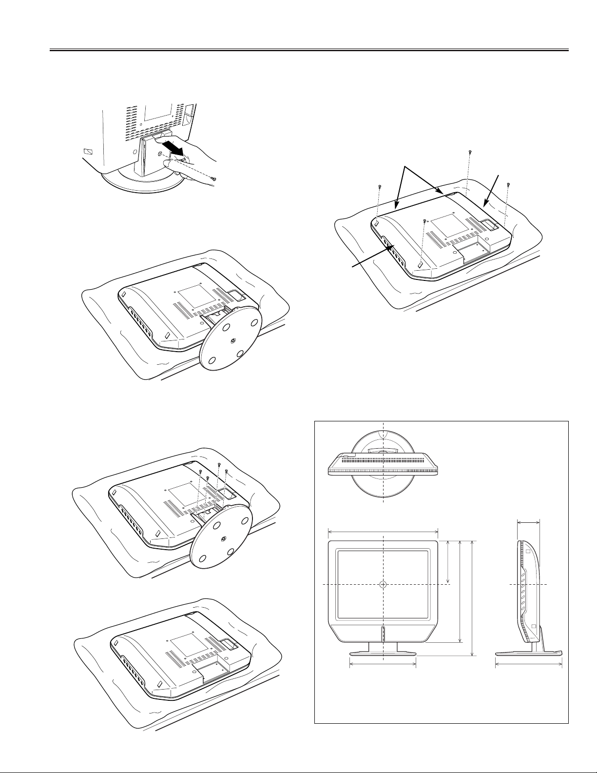
Stand Removal
1. Remove a screw and remove a stand cover.
2. Position TV face down on a padded or cushioned
surface to protect the screen and finish.
3. Remove 4 screws to take the stand off.
CAUTION: Hold the stand firmly as you remove the
last screw.
Cabinet Back Removal
1. Remove 4 screws and remove the Cabinet Back.
Note: The cabinet back may still be a little tight due to the
snaps at the other locations.
Snap
Snap
Snap
[ Details of Dimensions ]
373 mm
Screen Center
226.2 mm
148.5 mm
345.2 mm
75 mm
390.2 mm
226.2 mm
Page 10
Mechanical Disassembly
-10-
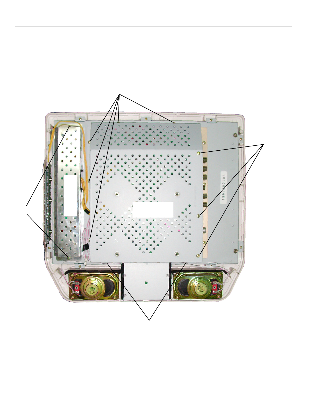
Chassis Removal
Remove the cabinet back and shield cover and can be seen the chassis.
To remove the Shield Cover of Main PWB, remove 10 screws.
To remove the Shield Cover of Inverter PWB, remove 2 screws.
Screw
Screw
Screw
Screw
Shield Cover of
Main PWB
Shield Cover of
Inverter PWB
Page 11
Mechanical Disassembly
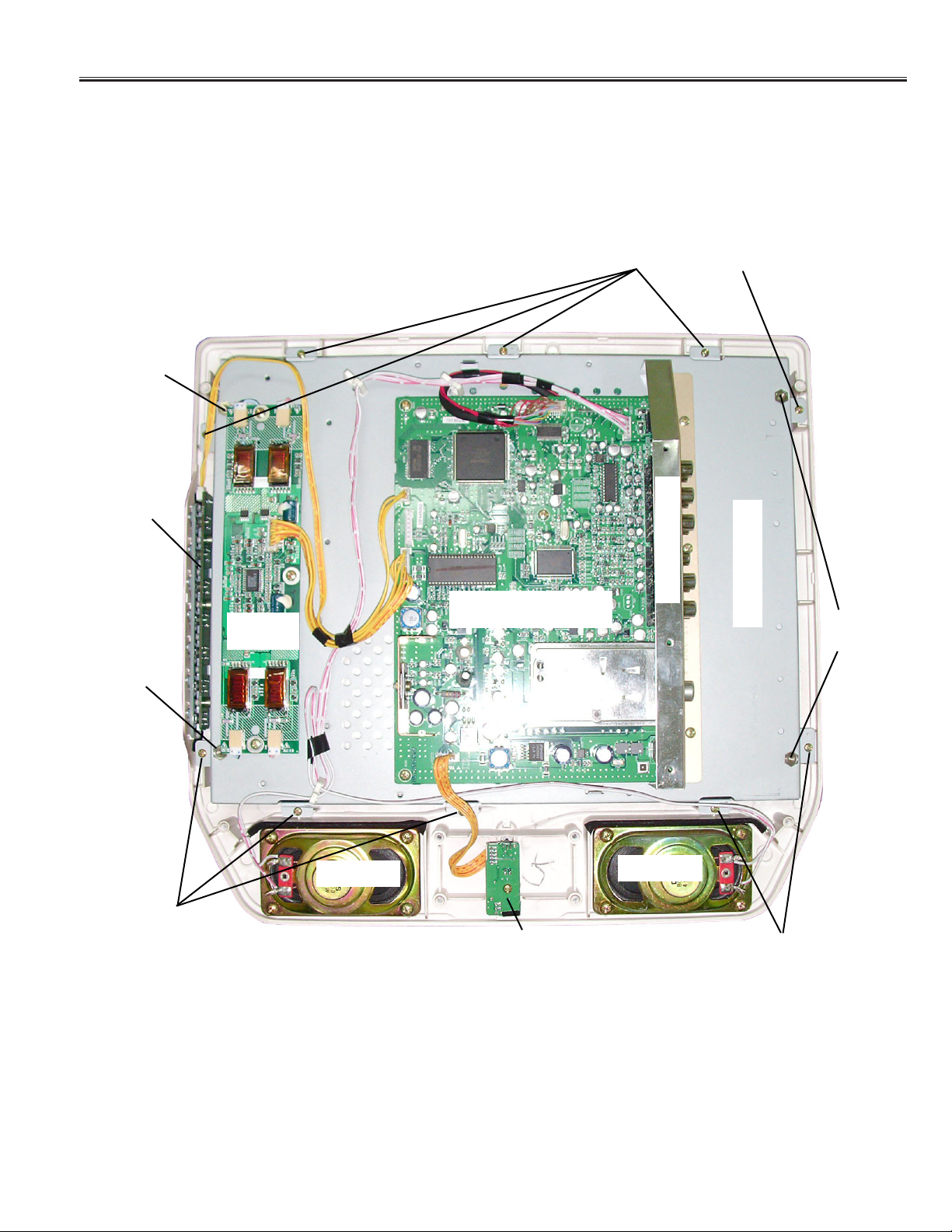
-11-
Location of Circuit Board and Electrical Parts
ASSY PWB MAIN
ASSY PWB
KEY BOARD
ASSY PWB
LED BOARD
Inverter
Board
Chassis Base
Speaker
Speaker
Terminal Panel
Screw
(for Chassis Base)
Screw (for Chassis Base)
Screw
(for Chassis Base)
Screw
(for Panel)
Screw
(for Panel)
Screw
(for Panel)
Page 12

Cabinet Parts List
Note: Parts order must contain Service Ref. No., Part No., and descriptions.
-12-
1 610 314 6454 CABINET FRONT-N2JP
2 610 314 7116 DEC IND-N2JP
3
610 316 5790 ASSY,BUTTON-N2JP
4 610 315 3223 COMPL,STAND-N2JP
4a 610 315 9645 STAND BASE-N2JP
4b 610 315 9508 COVER STAND N2JP
4c 610 316 1853 RUBBER PAD-N2PA
5 610 314 7062 CABINET BACK-N2JP
6 610 314 7109 COVER JACK-N2JP
7 645 068 8201 REMOCON,JXPSA
8 652 001 4114 AC-DC ADAPTOR
9 ASIA/MIDDLE EAST:
645 072 1564 CORD,POWER-1.8MK,EU
AUSTRALIA:
645 072 8945 CORD,POWER-1.8MK,AUS
SAUDI ARABIA:
645 072 8938 CORD,POWER-1.8MK,SAU
610 316 7510 INSTRUCTIONS MANUAL-N2JVZ
(IN ENGLISH)
Key No. Part No. Description Key No. Part No. Description
1
3
4a
4
5
7
4b
4c
6
2
8
9
Page 13

-13-
N2JVZ
OUT OF CIRCUIT BOARD
MISCELLANEOUS
Q901 645 066 9620 LCD (M150X3-L04)
- 610 313 1719 CORD 20P 1.25MM(LVDS)
(MAIN - LVDS PANEL)
SP901 652 001 1724 SPEAKER,4
652 001 3797 SPEAKER,4
SP902 652 001 1724 SPEAKER,4
652 001 3797 SPEAKER,4
U901 645 068 0731 UNIT,INVERTER
655 000 6653 ASSY PWB MAIN N2JP
1LG0B10Z0610A
TRANSISTOR
Q101 405 014 4509 TR 2SC2412K T146 R
405 014 4608 TR 2SC2412K T146 S
405 015 8704 TR 2SC2812-L6-TB
405 015 8902 TR 2SC2812-L7-TB
405 163 1602 TR 2SC2812N-L6-TB0
405 163 1701 TR 2SC2812N-L7-TB0
405 173 9803 TR 2SC3928A1R
405 173 9902 TR 2SC3928A1S
Q102 405 202 7701 TR TPC8109
Q201 405 014 4509 TR 2SC2412K T146 R
405 014 4608 TR 2SC2412K T146 S
405 015 8704 TR 2SC2812-L6-TB
405 015 8902 TR 2SC2812-L7-TB
405 163 1602 TR 2SC2812N-L6-TB0
405 163 1701 TR 2SC2812N-L7-TB0
405 173 9803 TR 2SC3928A1R
405 173 9902 TR 2SC3928A1S
Q202 405 134 5905 TR 2SA1037AK-T146-R
405 147 2205 TR 2SA1037AK-S-T146
405 002 0308 TR 2SA1037K T146 R
405 002 0407 TR 2SA1037K T146 S
405 002 6706 TR 2SA1179-M6-TB
405 002 6904 TR 2SA1179-M7-TB
405 163 1503 TR 2SA1179N-M6-TB
405 163 2708 TR 2SA1179N-M7-TB
405 173 9605 TR 2SA1235A1E
405 173 9704 TR 2SA1235A1F
Q203 405 134 5905 TR 2SA1037AK-T146-R
405 147 2205 TR 2SA1037AK-S-T146
405 002 0308 TR 2SA1037K T146 R
405 002 0407 TR 2SA1037K T146 S
405 002 6706 TR 2SA1179-M6-TB
405 002 6904 TR 2SA1179-M7-TB
405 163 1503 TR 2SA1179N-M6-TB
405 163 2708 TR 2SA1179N-M7-TB
405 173 9605 TR 2SA1235A1E
405 173 9704 TR 2SA1235A1F
Q204 405 014 4509 TR 2SC2412K T146 R
405 014 4608 TR 2SC2412K T146 S
405 015 8704 TR 2SC2812-L6-TB
!
!
Chassis Electrical Parts List
Ref. No. Part No. Description Ref. No. Part No. Description
Product safety should be considered when a component replacement is made in any area of a receiver.
Components indicated by a mark in this parts list and the circuit diagram show components whose value have
special significance to product safety. It is particularly recommended that only parts specified on the following parts
list be used for components replacement pointed out by the mark.
!
Note: Parts order must contain Service Ref. No., Part No., and descriptions. The main PCB unit will be supplied without tuner and
flyback transformer. They should be ordered separately.
NOTES:
Read description in the Capacitor and Resistor as follows:
CAPACITOR
CERAMIC 100P K 50V
Rated Voltage
Tolerance Symbols:
Less than 10pF
A : Not specified B : ±0.1pF C : ±0.25pF
D : ±0.5pF F : ±1PF G : ±2pF
R : ±0.25-0pF S : ±0-0.25pF E : +0-1pF
More than 10pF
A : Not specified B : ±0.1% C : ±0.25%
D : ±0.5% F : ±1% G : ±2%
H : ±3% J : ±5% K : ±10%
L : ±15% M : ±20% N : ±30%
P : +100-0% Q : +30-10% T : +50-10%
U : +75-10% V : +20-10% W : +100-10%
X : +40-20% Y : +150-10% Z : +80-20%
Rated value: P=pico farad, U=micro farad
Material:
CERAMIC........... Ceramic
MT-PAPER......... Metallized Paper
POLYESTER...... Polyester
MT-POLYEST.....Metallized Polyester
POLYPRO.......... Polypropylene
MT-POLYPRO....Metallized Polypropylene
COMPO FILM.....Composite film
MT-COMPO........Metallized Composite
STYRENE...........Styrene
TA-SOLID........... Tantalum Solid
AL-SOLID........... Aluminium Solid
ELECT................ Electrolytic
NP-ELECT..........Non-polarised Electrolytic
OS-SOLID.......... Aluminium Solid with Organic Semiconductive Electrolytic
DL-ELECT.......... Double Layered Electrolytic
RESISTOR
CARBON 4.7K J A 1/4W
Rated Wattage
Performance Symbols:
A: General B: Non flammable Z: Low noise
Other: Temperature coefficient
Tolerance Symbols:
A: ±0.05% B: ±0.1% C: ±0.25% D: ±0.5%
F: ±1% G: ±2% J: ±5% K: ±10%
M: ±20% P: +5-15%
Rated value, ohms:
K: 1,000, M: 1,000,000
Material:
CARBON........... Carbon
MT-FILM............ Metal Film
OXIDE-MT......... Oxide Metal Film
SOLID................ Composition
MT-GLAZE......... Metal Glaze
WIRE WOUND...Wire Wound
CERAMIC RES.. Ceramic
FUSIBLE RES....Fusible
Page 14

-14-
N2JVZ
405 015 8902 TR 2SC2812-L7-TB
405 163 1602 TR 2SC2812N-L6-TB0
405 163 1701 TR 2SC2812N-L7-TB0
405 173 9803 TR 2SC3928A1R
405 173 9902 TR 2SC3928A1S
Q205 405 014 4509 TR 2SC2412K T146 R
405 014 4608 TR 2SC2412K T146 S
405 015 8704 TR 2SC2812-L6-TB
405 015 8902 TR 2SC2812-L7-TB
405 163 1602 TR 2SC2812N-L6-TB0
405 163 1701 TR 2SC2812N-L7-TB0
405 173 9803 TR 2SC3928A1R
405 173 9902 TR 2SC3928A1S
Q206 405 014 4509 TR 2SC2412K T146 R
405 014 4608 TR 2SC2412K T146 S
405 015 8704 TR 2SC2812-L6-TB
405 015 8902 TR 2SC2812-L7-TB
405 163 1602 TR 2SC2812N-L6-TB0
405 163 1701 TR 2SC2812N-L7-TB0
405 173 9803 TR 2SC3928A1R
405 173 9902 TR 2SC3928A1S
Q207 405 014 4509 TR 2SC2412K T146 R
405 014 4608 TR 2SC2412K T146 S
405 015 8704 TR 2SC2812-L6-TB
405 015 8902 TR 2SC2812-L7-TB
405 163 1602 TR 2SC2812N-L6-TB0
405 163 1701 TR 2SC2812N-L7-TB0
405 173 9803 TR 2SC3928A1R
405 173 9902 TR 2SC3928A1S
Q209 405 014 4509 TR 2SC2412K T146 R
405 014 4608 TR 2SC2412K T146 S
405 015 8704 TR 2SC2812-L6-TB
405 015 8902 TR 2SC2812-L7-TB
405 163 1602 TR 2SC2812N-L6-TB0
405 163 1701 TR 2SC2812N-L7-TB0
405 173 9803 TR 2SC3928A1R
405 173 9902 TR 2SC3928A1S
Q210 405 014 4509 TR 2SC2412K T146 R
405 014 4608 TR 2SC2412K T146 S
405 015 8704 TR 2SC2812-L6-TB
405 015 8902 TR 2SC2812-L7-TB
405 163 1602 TR 2SC2812N-L6-TB0
405 163 1701 TR 2SC2812N-L7-TB0
405 173 9803 TR 2SC3928A1R
405 173 9902 TR 2SC3928A1S
Q212 405 014 4509 TR 2SC2412K T146 R
405 014 4608 TR 2SC2412K T146 S
405 015 8704 TR 2SC2812-L6-TB
405 015 8902 TR 2SC2812-L7-TB
405 163 1602 TR 2SC2812N-L6-TB0
405 163 1701 TR 2SC2812N-L7-TB0
405 173 9803 TR 2SC3928A1R
405 173 9902 TR 2SC3928A1S
Q213 405 014 4509 TR 2SC2412K T146 R
405 014 4608 TR 2SC2412K T146 S
405 015 8704 TR 2SC2812-L6-TB
405 015 8902 TR 2SC2812-L7-TB
405 163 1602 TR 2SC2812N-L6-TB0
405 163 1701 TR 2SC2812N-L7-TB0
405 173 9803 TR 2SC3928A1R
405 173 9902 TR 2SC3928A1S
Q301 405 014 4509 TR 2SC2412K T146 R
405 014 4608 TR 2SC2412K T146 S
405 015 8704 TR 2SC2812-L6-TB
405 015 8902 TR 2SC2812-L7-TB
405 163 1602 TR 2SC2812N-L6-TB0
405 163 1701 TR 2SC2812N-L7-TB0
405 173 9803 TR 2SC3928A1R
405 173 9902 TR 2SC3928A1S
Q302 405 134 5905 TR 2SA1037AK-T146-R
405 147 2205 TR 2SA1037AK-S-T146
405 002 0308 TR 2SA1037K T146 R
405 002 0407 TR 2SA1037K T146 S
405 002 6706 TR 2SA1179-M6-TB
405 002 6904 TR 2SA1179-M7-TB
405 163 1503 TR 2SA1179N-M6-TB
405 163 2708 TR 2SA1179N-M7-TB
405 173 9605 TR 2SA1235A1E
405 173 9704 TR 2SA1235A1F
Q303 405 014 4509 TR 2SC2412K T146 R
405 014 4608 TR 2SC2412K T146 S
405 015 8704 TR 2SC2812-L6-TB
405 015 8902 TR 2SC2812-L7-TB
405 163 1602 TR 2SC2812N-L6-TB0
405 163 1701 TR 2SC2812N-L7-TB0
405 173 9803 TR 2SC3928A1R
405 173 9902 TR 2SC3928A1S
Q304 405 134 5905 TR 2SA1037AK-T146-R
405 147 2205 TR 2SA1037AK-S-T146
405 002 0308 TR 2SA1037K T146 R
405 002 0407 TR 2SA1037K T146 S
405 002 6706 TR 2SA1179-M6-TB
405 002 6904 TR 2SA1179-M7-TB
405 163 1503 TR 2SA1179N-M6-TB
405 163 2708 TR 2SA1179N-M7-TB
405 173 9605 TR 2SA1235A1E
405 173 9704 TR 2SA1235A1F
Q305 405 014 4509 TR 2SC2412K T146 R
405 014 4608 TR 2SC2412K T146 S
405 015 8704 TR 2SC2812-L6-TB
405 015 8902 TR 2SC2812-L7-TB
405 163 1602 TR 2SC2812N-L6-TB0
405 163 1701 TR 2SC2812N-L7-TB0
405 173 9803 TR 2SC3928A1R
405 173 9902 TR 2SC3928A1S
Q306 405 134 5905 TR 2SA1037AK-T146-R
405 147 2205 TR 2SA1037AK-S-T146
405 002 0308 TR 2SA1037K T146 R
405 002 0407 TR 2SA1037K T146 S
405 002 6706 TR 2SA1179-M6-TB
405 002 6904 TR 2SA1179-M7-TB
405 163 1503 TR 2SA1179N-M6-TB
405 163 2708 TR 2SA1179N-M7-TB
405 173 9605 TR 2SA1235A1E
405 173 9704 TR 2SA1235A1F
Q307 405 014 4509 TR 2SC2412K T146 R
405 014 4608 TR 2SC2412K T146 S
405 015 8704 TR 2SC2812-L6-TB
405 015 8902 TR 2SC2812-L7-TB
405 163 1602 TR 2SC2812N-L6-TB0
405 163 1701 TR 2SC2812N-L7-TB0
405 173 9803 TR 2SC3928A1R
405 173 9902 TR 2SC3928A1S
Q308 405 134 5905 TR 2SA1037AK-T146-R
405 147 2205 TR 2SA1037AK-S-T146
405 002 0308 TR 2SA1037K T146 R
405 002 0407 TR 2SA1037K T146 S
405 002 6706 TR 2SA1179-M6-TB
405 002 6904 TR 2SA1179-M7-TB
405 163 1503 TR 2SA1179N-M6-TB
405 163 2708 TR 2SA1179N-M7-TB
405 173 9605 TR 2SA1235A1E
405 173 9704 TR 2SA1235A1F
Q309 405 014 4509 TR 2SC2412K T146 R
Ref. No. Part No. Description Ref. No. Part No. Description
Page 15

405 014 4608 TR 2SC2412K T146 S
405 015 8704 TR 2SC2812-L6-TB
405 015 8902 TR 2SC2812-L7-TB
405 163 1602 TR 2SC2812N-L6-TB0
405 163 1701 TR 2SC2812N-L7-TB0
405 173 9803 TR 2SC3928A1R
405 173 9902 TR 2SC3928A1S
Q310 405 014 4509 TR 2SC2412K T146 R
405 014 4608 TR 2SC2412K T146 S
405 015 8704 TR 2SC2812-L6-TB
405 015 8902 TR 2SC2812-L7-TB
405 163 1602 TR 2SC2812N-L6-TB0
405 163 1701 TR 2SC2812N-L7-TB0
405 173 9803 TR 2SC3928A1R
405 173 9902 TR 2SC3928A1S
Q311 405 014 4509 TR 2SC2412K T146 R
405 014 4608 TR 2SC2412K T146 S
405 015 8704 TR 2SC2812-L6-TB
405 015 8902 TR 2SC2812-L7-TB
405 163 1602 TR 2SC2812N-L6-TB0
405 163 1701 TR 2SC2812N-L7-TB0
405 173 9803 TR 2SC3928A1R
405 173 9902 TR 2SC3928A1S
Q601 405 014 4509 TR 2SC2412K T146 R
405 014 4608 TR 2SC2412K T146 S
405 015 8704 TR 2SC2812-L6-TB
405 015 8902 TR 2SC2812-L7-TB
405 163 1602 TR 2SC2812N-L6-TB0
405 163 1701 TR 2SC2812N-L7-TB0
405 173 9803 TR 2SC3928A1R
405 173 9902 TR 2SC3928A1S
INTEGRATED CIRCUIT
IC101 409 477 9002 IC LM2596S-5.0
IC102 409 598 6904 IC RC1587M-3.3
IC103 409 598 8007 IC TA78L09F
IC104 409 598 5303 IC TA48025F
IC105 409 598 5105 IC TAR5S15
IC106 409 568 8907 IC LT1615ES5-1
IC107 409 598 5204 IC TAR5S25
IC201 409 585 2209 IC TMP88PS34N
IC202 410 495 8007 IC AT24C16A-10PI-2.7
409 459 4506 IC 24LC16B/P
IC204 410 507 1903 IC TC74VHCT04AFT
IC205 409 370 8003 IC TA7805F
IC206 409 370 8003 IC TA7805F
IC301 409 598 5402 IC TC90L01N
IC302 409 551 7603 IC LA4263-E
IC303 409 450 3102 IC NJM2535M
IC601 409 581 3705 IC TC90A92AFG
IC701 409 581 3606 IC TC6398AF
IC702 410 503 6100 IC K4S643232F-TC60
410 520 1102 IC K4S643232H-TC60
IC801 409 598 6706 IC DS90C385MTD
CAPACITOR
C101 404 096 8009 ELECT 1000U M 16V
404 084 2903 ELECT 1000U M 16V
403 045 1504 ELECT 1000U M 25V
C102 404 091 2606 CERAMIC 0.1U K 50V
C103 404 096 8009 ELECT 1000U M 16V
404 084 2903 ELECT 1000U M 16V
403 045 1504 ELECT 1000U M 25V
C104 404 091 2606 CERAMIC 0.1U K 50V
C105 404 095 6907 ELECT 100U M 16V
403 229 3508 ELECT 100U M 16V
C106 404 091 2606 CERAMIC 0.1U K 50V
C109 403 375 7405 OS-SOLID 330U M 10V
C110 404 091 2606 CERAMIC 0.1U K 50V
C111 404 095 6907 ELECT 100U M 16V
403 229 3508 ELECT 100U M 16V
C112 404 091 2606 CERAMIC 0.1U K 50V
C113 404 084 3306 ELECT 470U M 16V
403 044 1703 ELECT 470U M 16V
C114 404 091 2606 CERAMIC 0.1U K 50V
C116 404 091 2606 CERAMIC 0.1U K 50V
C117 404 095 6907 ELECT 100U M 16V
403 229 3508 ELECT 100U M 16V
C118 404 091 2606 CERAMIC 0.1U K 50V
C120 404 091 2606 CERAMIC 0.1U K 50V
C121 404 095 6907 ELECT 100U M 16V
403 229 3508 ELECT 100U M 16V
C123 404 091 2606 CERAMIC 0.1U K 50V
C124 404 091 2606 CERAMIC 0.1U K 50V
C125 403 403 0705 ELECT 220U M 16V
403 381 5600 ELECT 220U M 16
C126 404 098 5907 ELECT 10U M 50V
403 175 0804 ELECT 10U M 50V
C128 404 091 2606 CERAMIC 0.1U K 50V
C129 404 091 2606 CERAMIC 0.1U K 50V
C130 404 095 6907 ELECT 100U M 16V
403 229 3508 ELECT 100U M 16V
C131 404 091 2606 CERAMIC 0.1U K 50V
C132 404 096 8009 ELECT 1000U M 16V
404 084 2903 ELECT 1000U M 16V
403 045 1504 ELECT 1000U M 25V
C133 403 280 1604 ELECT 220U M 16V
C134 403 403 0705 ELECT 220U M 16V
403 381 5600 ELECT 220U M 16
C135 403 280 1604 ELECT 220U M 16V
C136 403 280 1604 ELECT 220U M 16V
C201 404 094 3303 ELECT 1.0U M 50V
403 162 6208 ELECT 1U M 50V
C202 404 091 2606 CERAMIC 0.1U K 50V
C203 404 091 2606 CERAMIC 0.1U K 50V
C204 404 094 0104 ELECT 10U M 16V
403 335 0309 ELECT 10U M 16V
C205 404 095 6907 ELECT 100U M 16V
403 229 3508 ELECT 100U M 16V
C206 404 091 2606 CERAMIC 0.1U K 50V
C207 404 094 0104 ELECT 10U M 16V
403 335 0309 ELECT 10U M 16V
C211 404 094 8100 CERAMIC 33P J 50V
403 155 1609 CERAMIC 33P J 50V
C212 404 094 8100 CERAMIC 33P J 50V
403 155 1609 CERAMIC 33P J 50V
C213 404 094 6403 CERAMIC 100P J 50V
403 157 3601 CERAMIC 100P J 50V
C214 404 091 2606 CERAMIC 0.1U K 50V
C215 404 095 6907 ELECT 100U M 16V
403 229 3508 ELECT 100U M 16V
C216 404 095 6907 ELECT 100U M 16V
403 229 3508 ELECT 100U M 16V
C217 404 091 2606 CERAMIC 0.1U K 50V
C218 403 386 0907 ELECT 100U M 16V
403 381 5303 ELECT 100U M 16
C219 404 091 2606 CERAMIC 0.1U K 50V
C220 403 386 0907 ELECT 100U M 16V
403 381 5303 ELECT 100U M 16
C221 404 094 0104 ELECT 10U M 16V
403 335 0309 ELECT 10U M 16V
C222 404 094 3303 ELECT 1.0U M 50V
403 162 6208 ELECT 1U M 50V
C223 404 094 3303 ELECT 1.0U M 50V
-15-
N2JVZ
Ref. No. Part No. Description Ref. No. Part No. Description
Page 16

-16-
N2JVZ
403 162 6208 ELECT 1U M 50V
C224 404 094 7608 CERAMIC 22P J 50V
403 145 9905 CERAMIC 22P J 50V
C225 404 094 7608 CERAMIC 22P J 50V
403 145 9905 CERAMIC 22P J 50V
C226 404 091 2606 CERAMIC 0.1U K 50V
C227 404 094 0104 ELECT 10U M 16V
403 335 0309 ELECT 10U M 16V
C230 404 094 0104 ELECT 10U M 16V
403 335 0309 ELECT 10U M 16V
C231 404 094 6304 CERAMIC 10P J 50V
C232 404 094 6304 CERAMIC 10P J 50V
C233 404 094 6304 CERAMIC 10P J 50V
C234 404 094 6304 CERAMIC 10P J 50V
C235 404 094 6304 CERAMIC 10P J 50V
C237 404 094 6403 CERAMIC 100P J 50V
403 157 3601 CERAMIC 100P J 50V
C238 404 091 2606 CERAMIC 0.1U K 50V
C239 404 091 2606 CERAMIC 0.1U K 50V
C241 403 403 0705 ELECT 220U M 16V
403 381 5600 ELECT 220U M 16
C242 404 091 2606 CERAMIC 0.1U K 50V
C243 403 386 0907 ELECT 100U M 16V
403 381 5303 ELECT 100U M 16
C245 404 097 4901 ELECT 4.7U M 25V
403 162 5300 ELECT 4.7U M 25V
403 184 8402 ELECT 4.7U M 25V
C246 403 280 1604 ELECT 220U M 16V
C249 404 091 2606 CERAMIC 0.1U K 50V
C301 404 094 0104 ELECT 10U M 16V
403 335 0309 ELECT 10U M 16V
C302 404 094 0104 ELECT 10U M 16V
403 335 0309 ELECT 10U M 16V
C303 404 094 0104 ELECT 10U M 16V
403 335 0309 ELECT 10U M 16V
C304 404 094 0104 ELECT 10U M 16V
403 335 0309 ELECT 10U M 16V
C305 404 091 2606 CERAMIC 0.1U K 50V
C306 404 094 0104 ELECT 10U M 16V
403 335 0309 ELECT 10U M 16V
C307 404 094 0104 ELECT 10U M 16V
403 335 0309 ELECT 10U M 16V
C311 404 094 7608 CERAMIC 22P J 50V
403 145 9905 CERAMIC 22P J 50V
C312 404 094 7608 CERAMIC 22P J 50V
403 145 9905 CERAMIC 22P J 50V
C313 404 095 6907 ELECT 100U M 16V
403 229 3508 ELECT 100U M 16V
C314 404 091 2606 CERAMIC 0.1U K 50V
C328 404 095 6907 ELECT 100U M 16V
403 229 3508 ELECT 100U M 16V
C329 404 094 0104 ELECT 10U M 16V
403 335 0309 ELECT 10U M 16V
C330 404 094 6700 CERAMIC 12P J 50V
403 139 7108 CERAMIC 12P J 50V
C331 404 094 7806 CERAMIC 27P J 50V
403 157 2505 CERAMIC 27P J 50V
C332 404 091 2606 CERAMIC 0.1U K 50V
C333 404 094 7004 CERAMIC 15P J 50V
403 155 4204 CERAMIC 15P J 50V
C334 404 094 0104 ELECT 10U M 16V
403 335 0309 ELECT 10U M 16V
C335 404 094 6700 CERAMIC 12P J 50V
403 139 7108 CERAMIC 12P J 50V
C336 404 094 7004 CERAMIC 15P J 50V
403 155 4204 CERAMIC 15P J 50V
C337 404 094 7806 CERAMIC 27P J 50V
403 157 2505 CERAMIC 27P J 50V
C338 404 091 2606 CERAMIC 0.1U K 50V
C339 404 094 0104 ELECT 10U M 16V
403 335 0309 ELECT 10U M 16V
C340 404 094 6700 CERAMIC 12P J 50V
403 139 7108 CERAMIC 12P J 50V
C341 404 094 7004 CERAMIC 15P J 50V
403 155 4204 CERAMIC 15P J 50V
C342 404 094 7806 CERAMIC 27P J 50V
403 157 2505 CERAMIC 27P J 50V
C343 404 091 2606 CERAMIC 0.1U K 50V
C344 404 094 0104 ELECT 10U M 16V
403 335 0309 ELECT 10U M 16V
C345 404 094 6700 CERAMIC 12P J 50V
403 139 7108 CERAMIC 12P J 50V
C346 404 094 7004 CERAMIC 15P J 50V
403 155 4204 CERAMIC 15P J 50V
C347 404 094 7806 CERAMIC 27P J 50V
403 157 2505 CERAMIC 27P J 50V
C348 404 091 2606 CERAMIC 0.1U K 50V
C349 404 094 0104 ELECT 10U M 16V
403 335 0309 ELECT 10U M 16V
C350 404 094 0104 ELECT 10U M 16V
403 335 0309 ELECT 10U M 16V
C353 404 094 0104 ELECT 10U M 16V
403 335 0309 ELECT 10U M 16V
C354 404 094 0104 ELECT 10U M 16V
403 335 0309 ELECT 10U M 16V
C355 404 094 0104 ELECT 10U M 16V
403 335 0309 ELECT 10U M 16V
C356 404 094 0104 ELECT 10U M 16V
403 335 0309 ELECT 10U M 16V
C357 404 094 0401 ELECT 4.7U M 50V
403 175 3706 ELECT 4.7U M 50V
C358 403 403 5403 NP-ELECT 1U M 50V
403 397 9005 NP-ELECT 1.0U M 50V
C359 403 403 5403 NP-ELECT 1U M 50V
403 397 9005 NP-ELECT 1.0U M 50V
C360 404 094 0401 ELECT 4.7U M 50V
403 175 3706 ELECT 4.7U M 50V
C361 404 094 0401 ELECT 4.7U M 50V
403 175 3706 ELECT 4.7U M 50V
C362 404 091 2903 CERAMIC 0.015U K 50V
403 215 2409 CERAMIC 0.015U K 50V
C363 404 091 2903 CERAMIC 0.015U K 50V
403 215 2409 CERAMIC 0.015U K 50V
C364 404 094 0104 ELECT 10U M 16V
403 335 0309 ELECT 10U M 16V
C365 403 280 1604 ELECT 220U M 16V
C366 404 094 0401 ELECT 4.7U M 50V
403 175 3706 ELECT 4.7U M 50V
C367 404 096 8009 ELECT 1000U M 16V
404 084 2903 ELECT 1000U M 16V
403 045 1504 ELECT 1000U M 25V
C368 404 090 1204 CERAMIC 0.01U K 50V
403 215 2201 CERAMIC 0.01U K 50V
C369 404 084 3306 ELECT 470U M 16V
403 044 1703 ELECT 470U M 16V
C370 404 084 3306 ELECT 470U M 16V
403 044 1703 ELECT 470U M 16V
C371 404 097 4901 ELECT 4.7U M 25V
403 162 5300 ELECT 4.7U M 25V
403 184 8402 ELECT 4.7U M 25V
C372 404 094 3303 ELECT 1.0U M 50V
403 162 6208 ELECT 1U M 50V
C373 404 094 3303 ELECT 1.0U M 50V
403 162 6208 ELECT 1U M 50V
Ref. No. Part No. Description Ref. No. Part No. Description
Page 17

C601 404 094 3303 ELECT 1.0U M 50V
403 162 6208 ELECT 1U M 50V
C602 404 091 2606 CERAMIC 0.1U K 50V
C603 404 091 2606 CERAMIC 0.1U K 50V
C604 404 091 2606 CERAMIC 0.1U K 50V
C605 404 094 0104 ELECT 10U M 16V
403 335 0309 ELECT 10U M 16V
C606 404 091 2606 CERAMIC 0.1U K 50V
C607 404 094 9008 CERAMIC 68P J 50V
403 157 3304 CERAMIC 68P J 50V
C608 404 090 1204 CERAMIC 0.01U K 50V
403 215 2201 CERAMIC 0.01U K 50V
C609 404 090 1204 CERAMIC 0.01U K 50V
403 215 2201 CERAMIC 0.01U K 50V
C610 404 090 1204 CERAMIC 0.01U K 50V
403 215 2201 CERAMIC 0.01U K 50V
C611 404 090 1204 CERAMIC 0.01U K 50V
403 215 2201 CERAMIC 0.01U K 50V
C612 404 094 0104 ELECT 10U M 16V
403 335 0309 ELECT 10U M 16V
C613 404 091 2606 CERAMIC 0.1U K 50V
C614 404 090 1204 CERAMIC 0.01U K 50V
403 215 2201 CERAMIC 0.01U K 50V
C615 404 090 1204 CERAMIC 0.01U K 50V
403 215 2201 CERAMIC 0.01U K 50V
C616 404 090 1204 CERAMIC 0.01U K 50V
403 215 2201 CERAMIC 0.01U K 50V
C617 404 091 2606 CERAMIC 0.1U K 50V
C618 404 094 0104 ELECT 10U M 16V
403 335 0309 ELECT 10U M 16V
C619 404 090 1204 CERAMIC 0.01U K 50V
403 215 2201 CERAMIC 0.01U K 50V
C620 404 090 1204 CERAMIC 0.01U K 50V
403 215 2201 CERAMIC 0.01U K 50V
C621 404 094 6700 CERAMIC 12P J 50V
403 139 7108 CERAMIC 12P J 50V
C622 404 090 1204 CERAMIC 0.01U K 50V
403 215 2201 CERAMIC 0.01U K 50V
C623 404 094 0104 ELECT 10U M 16V
403 335 0309 ELECT 10U M 16V
C624 404 091 2606 CERAMIC 0.1U K 50V
C625 404 090 1204 CERAMIC 0.01U K 50V
403 215 2201 CERAMIC 0.01U K 50V
C626 404 094 0104 ELECT 10U M 16V
403 335 0309 ELECT 10U M 16V
C627 404 091 2606 CERAMIC 0.1U K 50V
C628 404 094 7608 CERAMIC 22P J 50V
403 145 9905 CERAMIC 22P J 50V
C629 404 090 1105 CERAMIC 1000P K 50V
403 113 3805 CERAMIC 1000P K 50V
C630 404 094 7608 CERAMIC 22P J 50V
403 145 9905 CERAMIC 22P J 50V
C631 404 094 7608 CERAMIC 22P J 50V
403 145 9905 CERAMIC 22P J 50V
C632 404 094 0104 ELECT 10U M 16V
403 335 0309 ELECT 10U M 16V
C634 404 094 0104 ELECT 10U M 16V
403 335 0309 ELECT 10U M 16V
C635 404 091 2606 CERAMIC 0.1U K 50V
C636 404 094 0104 ELECT 10U M 16V
403 335 0309 ELECT 10U M 16V
C637 404 091 2606 CERAMIC 0.1U K 50V
C638 404 094 0104 ELECT 10U M 16V
403 335 0309 ELECT 10U M 16V
C639 404 091 2606 CERAMIC 0.1U K 50V
C640 404 091 2606 CERAMIC 0.1U K 50V
C641 404 091 2606 CERAMIC 0.1U K 50V
C642 404 091 2606 CERAMIC 0.1U K 50V
C643 404 091 2606 CERAMIC 0.1U K 50V
C644 404 091 2606 CERAMIC 0.1U K 50V
C645 404 091 2606 CERAMIC 0.1U K 50V
C646 404 091 2606 CERAMIC 0.1U K 50V
C647 404 091 2606 CERAMIC 0.1U K 50V
C648 404 091 2606 CERAMIC 0.1U K 50V
C649 404 091 2606 CERAMIC 0.1U K 50V
C650 404 091 2606 CERAMIC 0.1U K 50V
C651 404 091 2606 CERAMIC 0.1U K 50V
C652 404 091 2606 CERAMIC 0.1U K 50V
C653 404 094 7301 CERAMIC 18P J 50V
403 139 7306 CERAMIC 18P J 50V
C654 404 090 1105 CERAMIC 1000P K 50V
403 113 3805 CERAMIC 1000P K 50V
C655 404 090 1204 CERAMIC 0.01U K 50V
403 215 2201 CERAMIC 0.01U K 50V
C701 404 095 6907 ELECT 100U M 16V
403 229 3508 ELECT 100U M 16V
C702 404 091 2606 CERAMIC 0.1U K 50V
C703 404 095 6907 ELECT 100U M 16V
403 229 3508 ELECT 100U M 16V
C704 404 091 2606 CERAMIC 0.1U K 50V
C705 404 094 0104 ELECT 10U M 16V
403 335 0309 ELECT 10U M 16V
C706 404 091 2606 CERAMIC 0.1U K 50V
C707 404 098 0704 ELECT 47U M 6.3V
403 175 3300 ELECT 47U M 16V
403 190 6607 ELECT 47U M 16V
C708 404 098 0704 ELECT 47U M 6.3V
403 175 3300 ELECT 47U M 16V
403 190 6607 ELECT 47U M 16V
C709 404 094 0104 ELECT 10U M 16V
403 335 0309 ELECT 10U M 16V
C710 404 091 2606 CERAMIC 0.1U K 50V
C711 404 091 2606 CERAMIC 0.1U K 50V
C712 404 091 2606 CERAMIC 0.1U K 50V
C713 404 091 2606 CERAMIC 0.1U K 50V
C714 404 095 6907 ELECT 100U M 16V
403 229 3508 ELECT 100U M 16V
C715 404 091 2606 CERAMIC 0.1U K 50V
C716 404 091 2606 CERAMIC 0.1U K 50V
C717 404 091 2606 CERAMIC 0.1U K 50V
C718 404 091 2606 CERAMIC 0.1U K 50V
C719 404 091 2606 CERAMIC 0.1U K 50V
C720 404 091 2606 CERAMIC 0.1U K 50V
C721 404 091 2606 CERAMIC 0.1U K 50V
C722 404 091 2606 CERAMIC 0.1U K 50V
C723 404 091 2606 CERAMIC 0.1U K 50V
C724 404 091 2606 CERAMIC 0.1U K 50V
C725 404 091 2606 CERAMIC 0.1U K 50V
C726 404 091 2606 CERAMIC 0.1U K 50V
C727 404 091 2606 CERAMIC 0.1U K 50V
C728 404 091 2606 CERAMIC 0.1U K 50V
C729 404 091 2606 CERAMIC 0.1U K 50V
C730 404 091 2606 CERAMIC 0.1U K 50V
C731 404 091 2606 CERAMIC 0.1U K 50V
C732 404 091 2606 CERAMIC 0.1U K 50V
C733 404 091 2606 CERAMIC 0.1U K 50V
C734 404 091 2606 CERAMIC 0.1U K 50V
C735 404 091 2606 CERAMIC 0.1U K 50V
C736 404 091 2606 CERAMIC 0.1U K 50V
C737 404 091 2606 CERAMIC 0.1U K 50V
C738 404 091 2606 CERAMIC 0.1U K 50V
C739 404 091 2606 CERAMIC 0.1U K 50V
C740 404 091 2606 CERAMIC 0.1U K 50V
C741 404 091 2606 CERAMIC 0.1U K 50V
-17-
N2JVZ
Ref. No. Part No. Description Ref. No. Part No. Description
Page 18

-18-
N2JVZ
C742 404 091 2606 CERAMIC 0.1U K 50V
C743 404 094 7608 CERAMIC 22P J 50V
403 145 9905 CERAMIC 22P J 50V
C744 404 094 7608 CERAMIC 22P J 50V
403 145 9905 CERAMIC 22P J 50V
C802 404 095 6907 ELECT 100U M 16V
403 229 3508 ELECT 100U M 16V
C803 404 091 2606 CERAMIC 0.1U K 50V
C804 404 098 0704 ELECT 47U M 6.3V
C806 404 098 0704 ELECT 47U M 6.3V
C807 404 091 2606 CERAMIC 0.1U K 50V
C808 404 098 0704 ELECT 47U M 6.3V
C809 404 091 2606 CERAMIC 0.1U K 50V
C810 404 091 2606 CERAMIC 0.1U K 50V
C811 404 091 2606 CERAMIC 0.1U K 50V
C812 404 091 2606 CERAMIC 0.1U K 50V
RESISTOR
RP601 645 021 0358 R-NETWORK 100X4 0.063W
RP602 645 021 0358 R-NETWORK 100X4 0.063W
RP701 645 021 0358 R-NETWORK 100X4 0.063W
RP702 645 021 0358 R-NETWORK 100X4 0.063W
RP703 645 021 0358 R-NETWORK 100X4 0.063W
RP704 645 021 0358 R-NETWORK 100X4 0.063W
RP705 645 021 0358 R-NETWORK 100X4 0.063W
RP706 645 021 0358 R-NETWORK 100X4 0.063W
RP707 645 021 0358 R-NETWORK 100X4 0.063W
R101 401 105 0603 MT-GLAZE 10K JA 1/16W
402 090 2504 MT-GLAZE 10K JA 1/16W
R102 401 105 0603 MT-GLAZE 10K JA 1/16W
402 090 2504 MT-GLAZE 10K JA 1/16W
R104 401 105 0603 MT-GLAZE 10K JA 1/16W
402 090 2504 MT-GLAZE 10K JA 1/16W
R105 401 113 9001 MT-GLAZE 240K JA 1/16W
R106 401 113 6703 MT-GLAZE 9.1K JA 1/16W
402 091 3203 MT-GLAZE 9.1K JA 1/16W
R107 401 105 0603 MT-GLAZE 10K JA 1/16W
402 090 2504 MT-GLAZE 10K JA 1/16W
R108 401 105 0603 MT-GLAZE 10K JA 1/16W
402 090 2504 MT-GLAZE 10K JA 1/16W
R201 401 105 4205 MT-GLAZE 33K JA 1/16W
402 090 7707 MT-GLAZE 33KJA 1 /16W
R202 401 105 2904 MT-GLAZE 22K JA 1/16W
402 090 6007 MT-GLAZE 22K JA 1/16W
R203 401 105 5202 MT-GLAZE 470 JA 1/16W
402 090 9404 MT-GLAZE 470JA 1 /16W
R204 401 105 2102 MT-GLAZE 18K JA 1/16W
402 090 5109 MT-GLAZE 18K JA 1/16W
R205 401 105 0603 MT-GLAZE 10K JA 1/16W
402 090 2504 MT-GLAZE 10K JA 1/16W
R206 401 105 5103 MT-GLAZE 47 JA 1/16W
402 090 9305 MT-GLAZE 47JA 1/ 16W
R207 401 105 5301 MT-GLAZE 4.7K JA 1/16W
402 090 9503 MT-GLAZE 4.7K JA 1/16W
R208 401 105 5301 MT-GLAZE 4.7K JA 1/16W
402 090 9503 MT-GLAZE 4.7K JA 1/16W
R209 401 105 0405 MT-GLAZE 100 JA 1/16W
402 090 2306 MT-GLAZE 100 JA 1/16W
R210 401 105 0405 MT-GLAZE 100 JA 1/16W
402 090 2306 MT-GLAZE 100 JA 1/16W
R211 401 105 5301 MT-GLAZE 4.7K JA 1/16W
402 090 9503 MT-GLAZE 4.7K JA 1/16W
R212 401 105 5301 MT-GLAZE 4.7K JA 1/16W
402 090 9503 MT-GLAZE 4.7K JA 1/16W
R213 401 105 0405 MT-GLAZE 100 JA 1/16W
402 090 2306 MT-GLAZE 100 JA 1/16W
R214 401 105 0405 MT-GLAZE 100 JA 1/16W
402 090 2306 MT-GLAZE 100 JA 1/16W
R216 401 105 0504 MT-GLAZE 1K JA 1/16W
402 090 2405 MT-GLAZE 1K JA 1/16W
R223 401 105 5103 MT-GLAZE 47 JA 1/16W
402 090 9305 MT-GLAZE 47JA 1/ 16W
R224 401 105 1501 MT-GLAZE 1.5K JA 1/16W
402 090 4201 MT-GLAZE 1.5K JA 1/16W
R225 401 105 1006 MT-GLAZE 1.2K JA 1/16W
402 090 3402 MT-GLAZE 1.2K JA 1/16W
R226 401 105 5103 MT-GLAZE 47 JA 1/16W
402 090 9305 MT-GLAZE 47JA 1/ 16W
R228 401 105 0405 MT-GLAZE 100 JA 1/16W
402 090 2306 MT-GLAZE 100 JA 1/16W
R229 401 105 0405 MT-GLAZE 100 JA 1/16W
402 090 2306 MT-GLAZE 100 JA 1/16W
R230 401 105 0603 MT-GLAZE 10K JA 1/16W
402 090 2504 MT-GLAZE 10K JA 1/16W
R232 401 105 0603 MT-GLAZE 10K JA 1/16W
402 090 2504 MT-GLAZE 10K JA 1/16W
R233 401 105 0603 MT-GLAZE 10K JA 1/16W
402 090 2504 MT-GLAZE 10K JA 1/16W
R238 401 105 0405 MT-GLAZE 100 JA 1/16W
402 090 2306 MT-GLAZE 100 JA 1/16W
R239 401 105 1709 MT-GLAZE 150K JA 1/16W
402 090 4409 MT-GLAZE 150K JA 1/16W
R240 401 105 4205 MT-GLAZE 33K JA 1/16W
402 090 7707 MT-GLAZE 33KJA 1 /16W
R243 401 105 5400 MT-GLAZE 47K JA 1/16W
402 090 9602 MT-GLAZE 47KJA 1 /16W
R244 401 105 0405 MT-GLAZE 100 JA 1/16W
402 090 2306 MT-GLAZE 100 JA 1/16W
R245 401 105 0405 MT-GLAZE 100 JA 1/16W
402 090 2306 MT-GLAZE 100 JA 1/16W
R246 401 105 0405 MT-GLAZE 100 JA 1/16W
402 090 2306 MT-GLAZE 100 JA 1/16W
R247 401 105 0405 MT-GLAZE 100 JA 1/16W
402 090 2306 MT-GLAZE 100 JA 1/16W
R248 401 105 1402 MT-GLAZE 150 JA 1/16W
402 090 4102 MT-GLAZE 150 JA 1/16W
R249 401 150 6001 MT-GLAZE 0.000 ZA 1/10W
R251 401 105 2805 MT-GLAZE 2.2K JA 1/16W
402 090 5901 MT-GLAZE 2.2K JA 1/16W
R252 401 105 0504 MT-GLAZE 1K JA 1/16W
402 090 2405 MT-GLAZE 1K JA 1/16W
R253 401 105 2102 MT-GLAZE 18K JA 1/16W
402 090 5109 MT-GLAZE 18K JA 1/16W
R254 401 150 6001 MT-GLAZE 0.000 ZA 1/10W
R256 401 105 0603 MT-GLAZE 10K JA 1/16W
402 090 2504 MT-GLAZE 10K JA 1/16W
R257 401 105 0603 MT-GLAZE 10K JA 1/16W
402 090 2504 MT-GLAZE 10K JA 1/16W
R258 401 105 0603 MT-GLAZE 10K JA 1/16W
402 090 2504 MT-GLAZE 10K JA 1/16W
R259 401 105 4700 MT-GLAZE 39K JA 1/16W
402 090 8605 MT-GLAZE 39KJA 1 /16W
R260 401 105 0603 MT-GLAZE 10K JA 1/16W
402 090 2504 MT-GLAZE 10K JA 1/16W
R261 401 105 0405 MT-GLAZE 100 JA 1/16W
402 090 2306 MT-GLAZE 100 JA 1/16W
R262 401 105 0405 MT-GLAZE 100 JA 1/16W
402 090 2306 MT-GLAZE 100 JA 1/16W
R268 401 105 0306 MT-GLAZE 10 JA 1/16W
402 090 2207 MT-GLAZE 10 JA 1/16W
R301 401 105 0603 MT-GLAZE 10K JA 1/16W
402 090 2504 MT-GLAZE 10K JA 1/16W
R302 401 105 0603 MT-GLAZE 10K JA 1/16W
402 090 2504 MT-GLAZE 10K JA 1/16W
Ref. No. Part No. Description Ref. No. Part No. Description
Page 19

R303 401 113 4402 MT-GLAZE 75 JA 1/16W
402 091 1902 MT-GLAZE 75JA 1/ 16W
R304 401 105 0603 MT-GLAZE 10K JA 1/16W
402 090 2504 MT-GLAZE 10K JA 1/16W
R305 401 113 4402 MT-GLAZE 75 JA 1/16W
402 091 1902 MT-GLAZE 75JA 1/ 16W
R306 401 105 0603 MT-GLAZE 10K JA 1/16W
402 090 2504 MT-GLAZE 10K JA 1/16W
R307 401 113 4402 MT-GLAZE 75 JA 1/16W
402 091 1902 MT-GLAZE 75JA 1/ 16W
R311 401 105 0405 MT-GLAZE 100 JA 1/16W
402 090 2306 MT-GLAZE 100 JA 1/16W
R312 401 105 0405 MT-GLAZE 100 JA 1/16W
402 090 2306 MT-GLAZE 100 JA 1/16W
R316 401 105 0603 MT-GLAZE 10K JA 1/16W
402 090 2504 MT-GLAZE 10K JA 1/16W
R317 401 113 4402 MT-GLAZE 75 JA 1/16W
402 091 1902 MT-GLAZE 75JA 1/ 16W
R318 401 113 4402 MT-GLAZE 75 JA 1/16W
402 091 1902 MT-GLAZE 75JA 1/ 16W
R319 401 105 5400 MT-GLAZE 47K JA 1/16W
402 090 9602 MT-GLAZE 47KJA 1 /16W
R320 401 105 4700 MT-GLAZE 39K JA 1/16W
402 090 8605 MT-GLAZE 39KJA 1 /16W
R321 401 105 0504 MT-GLAZE 1K JA 1/16W
402 090 2405 MT-GLAZE 1K JA 1/16W
R322 401 105 6506 MT-GLAZE 680 JA 1/16W
402 091 1506 MT-GLAZE 680JA 1 /16W
R323 401 105 5202 MT-GLAZE 470 JA 1/16W
402 090 9404 MT-GLAZE 470JA 1 /16W
R324 401 105 4106 MT-GLAZE 3.3K JA 1/16W
402 090 7608 MT-GLAZE 3.3K JA 1/16W
R325 401 105 1501 MT-GLAZE 1.5K JA 1/16W
402 090 4201 MT-GLAZE 1.5K JA 1/16W
R326 401 105 5400 MT-GLAZE 47K JA 1/16W
402 090 9602 MT-GLAZE 47KJA 1 /16W
R327 401 105 4700 MT-GLAZE 39K JA 1/16W
402 090 8605 MT-GLAZE 39KJA 1 /16W
R328 401 105 0504 MT-GLAZE 1K JA 1/16W
402 090 2405 MT-GLAZE 1K JA 1/16W
R329 401 105 6506 MT-GLAZE 680 JA 1/16W
402 091 1506 MT-GLAZE 680JA 1 /16W
R330 401 105 7909 MT-GLAZE 0.000 ZA 1/16W
402 095 1205 MT-GLAZE 0JA 1 /16W
R331 401 105 4106 MT-GLAZE 3.3K JA 1/16W
402 090 7608 MT-GLAZE 3.3K JA 1/16W
R332 401 105 1501 MT-GLAZE 1.5K JA 1/16W
402 090 4201 MT-GLAZE 1.5K JA 1/16W
R333 401 105 5400 MT-GLAZE 47K JA 1/16W
402 090 9602 MT-GLAZE 47KJA 1 /16W
R334 401 105 4700 MT-GLAZE 39K JA 1/16W
402 090 8605 MT-GLAZE 39KJA 1 /16W
R335 401 105 0504 MT-GLAZE 1K JA 1/16W
402 090 2405 MT-GLAZE 1K JA 1/16W
R336 401 105 6506 MT-GLAZE 680 JA 1/16W
402 091 1506 MT-GLAZE 680JA 1 /16W
R337 401 105 7909 MT-GLAZE 0.000 ZA 1/16W
402 095 1205 MT-GLAZE 0JA 1 /16W
R338 401 105 4106 MT-GLAZE 3.3K JA 1/16W
402 090 7608 MT-GLAZE 3.3K JA 1/16W
R339 401 105 1501 MT-GLAZE 1.5K JA 1/16W
402 090 4201 MT-GLAZE 1.5K JA 1/16W
R340 401 105 5400 MT-GLAZE 47K JA 1/16W
402 090 9602 MT-GLAZE 47KJA 1 /16W
R341 401 105 4700 MT-GLAZE 39K JA 1/16W
402 090 8605 MT-GLAZE 39KJA 1 /16W
R342 401 105 0504 MT-GLAZE 1K JA 1/16W
402 090 2405 MT-GLAZE 1K JA 1/16W
R343 401 105 6506 MT-GLAZE 680 JA 1/16W
402 091 1506 MT-GLAZE 680JA 1 /16W
R344 401 105 7909 MT-GLAZE 0.000 ZA 1/16W
402 095 1205 MT-GLAZE 0JA 1 /16W
R345 401 105 4106 MT-GLAZE 3.3K JA 1/16W
402 090 7608 MT-GLAZE 3.3K JA 1/16W
R346 401 105 1501 MT-GLAZE 1.5K JA 1/16W
402 090 4201 MT-GLAZE 1.5K JA 1/16W
R347 401 260 4201 MT-GLAZE 82 JA 1/3W
R348 401 260 4201 MT-GLAZE 82 JA 1/3W
R349 401 105 1709 MT-GLAZE 150K JA 1/16W
402 090 4409 MT-GLAZE 150K JA 1/16W
R350 401 105 1709 MT-GLAZE 150K JA 1/16W
402 090 4409 MT-GLAZE 150K JA 1/16W
R351 401 105 4205 MT-GLAZE 33K JA 1/16W
402 090 7707 MT-GLAZE 33KJA 1 /16W
R352 401 105 4205 MT-GLAZE 33K JA 1/16W
402 090 7707 MT-GLAZE 33KJA 1 /16W
R353 401 105 1006 MT-GLAZE 1.2K JA 1/16W
402 090 3402 MT-GLAZE 1.2K JA 1/16W
R354 401 105 1006 MT-GLAZE 1.2K JA 1/16W
402 090 3402 MT-GLAZE 1.2K JA 1/16W
R355 401 105 0702 MT-GLAZE 100K JA 1/16W
402 090 2603 MT-GLAZE 100K JA 1/16W
R356 401 105 0702 MT-GLAZE 100K JA 1/16W
402 090 2603 MT-GLAZE 100K JA 1/16W
R359 401 105 0504 MT-GLAZE 1K JA 1/16W
402 090 2405 MT-GLAZE 1K JA 1/16W
R360 401 105 5806 MT-GLAZE 56 JA 1/16W
402 091 0400 MT-GLAZE 56JA 1/ 16W
R361 401 105 0603 MT-GLAZE 10K JA 1/16W
402 090 2504 MT-GLAZE 10K JA 1/16W
R362 401 105 2706 MT-GLAZE 220 JA 1/16W
402 090 5802 MT-GLAZE 220 JA 1/16W
R363 401 105 0702 MT-GLAZE 100K JA 1/16W
402 090 2603 MT-GLAZE 100K JA 1/16W
R364 401 105 0603 MT-GLAZE 10K JA 1/16W
402 090 2504 MT-GLAZE 10K JA 1/16W
R365 401 105 2706 MT-GLAZE 220 JA 1/16W
402 090 5802 MT-GLAZE 220 JA 1/16W
R366 401 105 0702 MT-GLAZE 100K JA 1/16W
402 090 2603 MT-GLAZE 100K JA 1/16W
R367 401 105 1105 MT-GLAZE 12K JA 1/16W
402 090 3501 MT-GLAZE 12K JA 1/16W
R368 401 105 1105 MT-GLAZE 12K JA 1/16W
402 090 3501 MT-GLAZE 12K JA 1/16W
R369 401 105 0504 MT-GLAZE 1K JA 1/16W
402 090 2405 MT-GLAZE 1K JA 1/16W
R370 401 105 0504 MT-GLAZE 1K JA 1/16W
402 090 2405 MT-GLAZE 1K JA 1/16W
R371 401 105 5301 MT-GLAZE 4.7K JA 1/16W
402 090 9503 MT-GLAZE 4.7K JA 1/16W
R372 401 105 0603 MT-GLAZE 10K JA 1/16W
402 090 2504 MT-GLAZE 10K JA 1/16W
R373 401 105 0603 MT-GLAZE 10K JA 1/16W
402 090 2504 MT-GLAZE 10K JA 1/16W
R374 401 105 2706 MT-GLAZE 220 JA 1/16W
402 090 5802 MT-GLAZE 220 JA 1/16W
R375 402 079 5106 FUSIBLE RES 2.2 J- 1W
R376 401 105 5400 MT-GLAZE 47K JA 1/16W
402 090 9602 MT-GLAZE 47KJA 1 /16W
R377 401 105 5400 MT-GLAZE 47K JA 1/16W
402 090 9602 MT-GLAZE 47KJA 1 /16W
R378 401 105 4700 MT-GLAZE 39K JA 1/16W
402 090 8605 MT-GLAZE 39KJA 1 /16W
R379 401 113 4402 MT-GLAZE 75 JA 1/16W
-19-
N2JVZ
Ref. No. Part No. Description Ref. No. Part No. Description
Page 20

-20-
N2JVZ
402 091 1902 MT-GLAZE 75JA 1/ 16W
R389 401 105 2805 MT-GLAZE 2.2K JA 1/16W
402 090 5901 MT-GLAZE 2.2K JA 1/16W
R390 401 105 0504 MT-GLAZE 1K JA 1/16W
402 090 2405 MT-GLAZE 1K JA 1/16W
R391 401 105 2805 MT-GLAZE 2.2K JA 1/16W
402 090 5901 MT-GLAZE 2.2K JA 1/16W
R392 401 105 0504 MT-GLAZE 1K JA 1/16W
402 090 2405 MT-GLAZE 1K JA 1/16W
R601 401 105 1006 MT-GLAZE 1.2K JA 1/16W
402 090 3402 MT-GLAZE 1.2K JA 1/16W
R602 401 105 0504 MT-GLAZE 1K JA 1/16W
402 090 2405 MT-GLAZE 1K JA 1/16W
R603 401 105 3505 MT-GLAZE 270K JA 1/16W
402 090 7004 MT-GLAZE 270K JA 1/16W
R604 401 105 0405 MT-GLAZE 100 JA 1/16W
402 090 2306 MT-GLAZE 100 JA 1/16W
R605 401 105 4106 MT-GLAZE 3.3K JA 1/16W
402 090 7608 MT-GLAZE 3.3K JA 1/16W
R607 401 105 0405 MT-GLAZE 100 JA 1/16W
402 090 2306 MT-GLAZE 100 JA 1/16W
R608 401 105 0405 MT-GLAZE 100 JA 1/16W
402 090 2306 MT-GLAZE 100 JA 1/16W
R609 401 105 0603 MT-GLAZE 10K JA 1/16W
402 090 2504 MT-GLAZE 10K JA 1/16W
R610 401 105 2201 MT-GLAZE 180K JA 1/16W
402 090 5208 MT-GLAZE 180K JA 1/16W
R611 401 105 5905 MT-GLAZE 560 JA 1/16W
402 091 0509 MT-GLAZE 560JA 1 /16W
R612 401 105 0405 MT-GLAZE 100 JA 1/16W
402 090 2306 MT-GLAZE 100 JA 1/16W
R613 401 105 0405 MT-GLAZE 100 JA 1/16W
402 090 2306 MT-GLAZE 100 JA 1/16W
R614 401 105 0405 MT-GLAZE 100 JA 1/16W
402 090 2306 MT-GLAZE 100 JA 1/16W
R615 401 105 0405 MT-GLAZE 100 JA 1/16W
402 090 2306 MT-GLAZE 100 JA 1/16W
R701 401 105 7909 MT-GLAZE 0.000 ZA 1/16W
402 095 1205 MT-GLAZE 0JA 1 /16W
R702 401 105 0405 MT-GLAZE 100 JA 1/16W
402 090 2306 MT-GLAZE 100 JA 1/16W
R703 401 105 0405 MT-GLAZE 100 JA 1/16W
402 090 2306 MT-GLAZE 100 JA 1/16W
R704 401 105 0405 MT-GLAZE 100 JA 1/16W
402 090 2306 MT-GLAZE 100 JA 1/16W
R705 401 105 0405 MT-GLAZE 100 JA 1/16W
402 090 2306 MT-GLAZE 100 JA 1/16W
R706 401 105 0405 MT-GLAZE 100 JA 1/16W
402 090 2306 MT-GLAZE 100 JA 1/16W
R707 401 105 0405 MT-GLAZE 100 JA 1/16W
402 090 2306 MT-GLAZE 100 JA 1/16W
R708 401 105 0603 MT-GLAZE 10K JA 1/16W
402 090 2504 MT-GLAZE 10K JA 1/16W
R709 401 105 0405 MT-GLAZE 100 JA 1/16W
402 090 2306 MT-GLAZE 100 JA 1/16W
R710 401 105 0603 MT-GLAZE 10K JA 1/16W
402 090 2504 MT-GLAZE 10K JA 1/16W
R804 401 105 0603 MT-GLAZE 10K JA 1/16W
402 090 2504 MT-GLAZE 10K JA 1/16W
R805 401 105 0603 MT-GLAZE 10K JA 1/16W
402 090 2504 MT-GLAZE 10K JA 1/16W
R806 401 105 7909 MT-GLAZE 0.000 ZA 1/16W
402 095 1205 MT-GLAZE 0JA 1 /16W
R807 401 105 7909 MT-GLAZE 0.000 ZA 1/16W
402 095 1205 MT-GLAZE 0JA 1 /16W
COIL
L101 652 001 4084 INDUCTOR 22 UH
L102 645 037 4500 INDUCTOR,1000 OHM
L103 652 001 4091 INDUCTOR 33 UH
L104 652 001 4022 INDUCTOR 22 UH
L105 652 001 4022 INDUCTOR 22 UH
L106 645 037 4500 INDUCTOR,1000 OHM
L202 652 001 4022 INDUCTOR 22 UH
L204 652 001 4022 INDUCTOR 22 UH
L205 652 001 4022 INDUCTOR 22 UH
L207 645 025 7797 INDUCTOR,120 OHM
L301 645 002 5280 INDUCTOR,15U M
L302 645 002 5280 INDUCTOR,15U M
L303 645 002 5280 INDUCTOR,15U M
L304 645 002 5280 INDUCTOR,15U M
L601 645 040 6430 INDUCTOR,2.2U M
L602 645 040 6430 INDUCTOR,2.2U M
L603 645 040 6430 INDUCTOR,2.2U M
L605 645 040 6430 INDUCTOR,2.2U M
L607 645 040 6430 INDUCTOR,2.2U M
L608 645 001 5915 INDUCTOR,1.5U M
L609 645 040 6430 INDUCTOR,2.2U M
L610 645 040 6430 INDUCTOR,2.2U M
L611 645 040 6430 INDUCTOR,2.2U M
L612 645 040 6430 INDUCTOR,2.2U M
L701 645 040 6430 INDUCTOR,2.2U M
L702 645 040 6430 INDUCTOR,2.2U M
L703 645 040 6430 INDUCTOR,2.2U M
L704 645 040 6430 INDUCTOR,2.2U M
L705 645 040 6430 INDUCTOR,2.2U M
L706 645 025 7797 INDUCTOR,120 OHM
L802 645 040 6430 INDUCTOR,2.2U M
L803 645 040 6430 INDUCTOR,2.2U M
L804 645 040 6430 INDUCTOR,2.2U M
DIODE
D101 407 238 7106 DIODE CMS05
D102 407 238 7205 DIODE CRS04
D104 407 149 0807 DIODE 1SS355-TE-17
D108 407 149 0807 DIODE 1SS355-TE-17
D109 407 149 0807 DIODE 1SS355-TE-17
D110 407 149 0807 DIODE 1SS355-TE-17
D112 407 149 0807 DIODE 1SS355-TE-17
D201 407 055 8805 ZENER DIODE RD3.9EB1
D316 407 210 5403 DIODE RB551V-30-TE-17
MISCELLANEOUS
F101 423 029 2204 FUSE 125V 5A
423 028 0607 FUSE 125V 5A
IC704 645 066 4090 OSC,CRYSTAL 27MHZ
645 068 8843 OSC,CRYSTAL,27.000MHZ
IC705 645 066 4076 OSC,CRYSTAL 65MHZ
645 068 8836 OSC,CRYSTAL,65.000MHZ
P101 652 001 3988 SOCKET,DC
P302 645 006 4791 JACK,PHONE D3.6
P305 652 001 1960 SOCKET,DIN 4P
P306 652 001 3995 JACK,RCA-5(6-1)
P307 652 001 3490 JACK,RCA-6
SC301 645 055 3202 SURGE-ABSORBER
SC302 645 055 3202 SURGE-ABSORBER
SC303 645 055 3202 SURGE-ABSORBER
SC304 645 055 3202 SURGE-ABSORBER
SC305 645 055 3202 SURGE-ABSORBER
SC306 645 055 3202 SURGE-ABSORBER
SC307 645 055 3202 SURGE-ABSORBER
SC308 645 055 3202 SURGE-ABSORBER
SC309 645 055 3202 SURGE-ABSORBER
!
Ref. No. Part No. Description Ref. No. Part No. Description
Page 21

SC310 645 055 3202 SURGE-ABSORBER
SC311 645 055 3202 SURGE-ABSORBER
SC312 645 055 3202 SURGE-ABSORBER
SC313 645 055 3202 SURGE-ABSORBER
SC314 645 055 3202 SURGE-ABSORBER
S801 645 045 4257 PLUG,PWB 20P
TU201 645 068 0762 TUNER,TU/IF
X201 652 001 4046 OSC,CRYSTAL 16MHZ
X601 652 001 4053 OSC,CRYSTAL 42MHZ
655 000 6660 ASSY PWB KEY BOARD
1LG0B10Z0610B
CAPACITOR
C208 404 094 6403 CERAMIC 100P J 50V
403 157 3601 CERAMIC 100P J 50V
RESISTOR
R215 401 105 0504 MT-GLAZE 1K JA 1/16W
402 090 2405 MT-GLAZE 1K JA 1/16W
R217 401 105 1105 MT-GLAZE 12K JA 1/16W
402 090 3501 MT-GLAZE 12K JA 1/16W
R218 401 105 1600 MT-GLAZE 15K JA 1/16W
402 090 4300 MT-GLAZE 15K JA 1/16W
R219 401 105 7404 MT-GLAZE 8.2K JA 1/16W
402 091 2602 MT-GLAZE 8.2K JA 1/16W
R220 401 105 4106 MT-GLAZE 3.3K JA 1/16W
402 090 7608 MT-GLAZE 3.3K JA 1/16W
R221 401 105 3307 MT-GLAZE 2.7K JA 1/16W
402 090 6809 MT-GLAZE 2.7K JA 1/16W
R222 401 105 0504 MT-GLAZE 1K JA 1/16W
402 090 2405 MT-GLAZE 1K JA 1/16W
R236 401 105 4205 MT-GLAZE 33K JA 1/16W
402 090 7707 MT-GLAZE 33KJA 1 /16W
MISCELLANEOUS
K201 652 001 4008 SWITCH,PUSH 1P-1TX1
K202 652 001 4008 SWITCH,PUSH 1P-1TX1
K203 652 001 4008 SWITCH,PUSH 1P-1TX1
K204 652 001 4008 SWITCH,PUSH 1P-1TX1
K205 652 001 4008 SWITCH,PUSH 1P-1TX1
K206 652 001 4008 SWITCH,PUSH 1P-1TX1
K207 652 001 4008 SWITCH,PUSH 1P-1TX1
SC201 645 055 3202 SURGE-ABSORBER
SC202 645 055 3202 SURGE-ABSORBER
SC203 645 055 3202 SURGE-ABSORBER
SC204 645 055 3202 SURGE-ABSORBER
SC205 645 055 3202 SURGE-ABSORBER
SC206 645 055 3202 SURGE-ABSORBER
SC207 645 055 3202 SURGE-ABSORBER
655 000 6677 ASSY PWB LED BOARD
N2JP 1LG0B10Z0610C
TRANSISTOR
Q208 405 014 4509 TR 2SC2412K T146 R
405 014 4608 TR 2SC2412K T146 S
405 015 8704 TR 2SC2812-L6-TB
405 015 8902 TR 2SC2812-L7-TB
405 163 1602 TR 2SC2812N-L6-TB0
405 163 1701 TR 2SC2812N-L7-TB0
405 173 9803 TR 2SC3928A1R
405 173 9902 TR 2SC3928A1S
Q211 405 134 5905 TR 2SA1037AK-T146-R
405 147 2205 TR 2SA1037AK-S-T146
405 002 0308 TR 2SA1037K T146 R
405 002 0407 TR 2SA1037K T146 S
405 002 6706 TR 2SA1179-M6-TB
405 002 6904 TR 2SA1179-M7-TB
405 163 1503 TR 2SA1179N-M6-TB
405 163 2708 TR 2SA1179N-M7-TB
405 173 9605 TR 2SA1235A1E
405 173 9704 TR 2SA1235A1F
CAPACITOR
C209 403 309 1400 CERAMIC 1U Z 10
C210 404 091 2606 CERAMIC 0.1U K 50V
RESISTOR
R231 401 038 0602 MT-GLAZE 220 JA 1/10W
R235 401 038 0602 MT-GLAZE 220 JA 1/10W
R237 401 105 7909 MT-GLAZE 0.000 ZA 1/16W
402 095 1205 MT-GLAZE 0JA 1 /16W
DIODE
D202 407 196 7705 LED SLP-581D-51
408 050 8906 LED M209GRW
D203 407 065 6204 LED SLP-481B-51
408 052 9406 LED 204YD
MISCELLANEOUS
IC203 652 001 4039 UNIT,REMOCON,RECEIVER
-21-
N2JVZ
Ref. No. Part No. Description Ref. No. Part No. Description
Page 22

-22-
Page 23

-23-
Page 24

-14-
N2JVZ
405 015 8902 TR 2SC2812-L7-TB
405 163 1602 TR 2SC2812N-L6-TB0
405 163 1701 TR 2SC2812N-L7-TB0
405 173 9803 TR 2SC3928A1R
405 173 9902 TR 2SC3928A1S
Q205 405 014 4509 TR 2SC2412K T146 R
405 014 4608 TR 2SC2412K T146 S
405 015 8704 TR 2SC2812-L6-TB
405 015 8902 TR 2SC2812-L7-TB
405 163 1602 TR 2SC2812N-L6-TB0
405 163 1701 TR 2SC2812N-L7-TB0
405 173 9803 TR 2SC3928A1R
405 173 9902 TR 2SC3928A1S
Q206 405 014 4509 TR 2SC2412K T146 R
405 014 4608 TR 2SC2412K T146 S
405 015 8704 TR 2SC2812-L6-TB
405 015 8902 TR 2SC2812-L7-TB
405 163 1602 TR 2SC2812N-L6-TB0
405 163 1701 TR 2SC2812N-L7-TB0
405 173 9803 TR 2SC3928A1R
405 173 9902 TR 2SC3928A1S
Q207 405 014 4509 TR 2SC2412K T146 R
405 014 4608 TR 2SC2412K T146 S
405 015 8704 TR 2SC2812-L6-TB
405 015 8902 TR 2SC2812-L7-TB
405 163 1602 TR 2SC2812N-L6-TB0
405 163 1701 TR 2SC2812N-L7-TB0
405 173 9803 TR 2SC3928A1R
405 173 9902 TR 2SC3928A1S
Q209 405 014 4509 TR 2SC2412K T146 R
405 014 4608 TR 2SC2412K T146 S
405 015 8704 TR 2SC2812-L6-TB
405 015 8902 TR 2SC2812-L7-TB
405 163 1602 TR 2SC2812N-L6-TB0
405 163 1701 TR 2SC2812N-L7-TB0
405 173 9803 TR 2SC3928A1R
405 173 9902 TR 2SC3928A1S
Q210 405 014 4509 TR 2SC2412K T146 R
405 014 4608 TR 2SC2412K T146 S
405 015 8704 TR 2SC2812-L6-TB
405 015 8902 TR 2SC2812-L7-TB
405 163 1602 TR 2SC2812N-L6-TB0
405 163 1701 TR 2SC2812N-L7-TB0
405 173 9803 TR 2SC3928A1R
405 173 9902 TR 2SC3928A1S
Q212 405 014 4509 TR 2SC2412K T146 R
405 014 4608 TR 2SC2412K T146 S
405 015 8704 TR 2SC2812-L6-TB
405 015 8902 TR 2SC2812-L7-TB
405 163 1602 TR 2SC2812N-L6-TB0
405 163 1701 TR 2SC2812N-L7-TB0
405 173 9803 TR 2SC3928A1R
405 173 9902 TR 2SC3928A1S
Q213 405 014 4509 TR 2SC2412K T146 R
405 014 4608 TR 2SC2412K T146 S
405 015 8704 TR 2SC2812-L6-TB
405 015 8902 TR 2SC2812-L7-TB
405 163 1602 TR 2SC2812N-L6-TB0
405 163 1701 TR 2SC2812N-L7-TB0
405 173 9803 TR 2SC3928A1R
405 173 9902 TR 2SC3928A1S
Q301 405 014 4509 TR 2SC2412K T146 R
405 014 4608 TR 2SC2412K T146 S
405 015 8704 TR 2SC2812-L6-TB
405 015 8902 TR 2SC2812-L7-TB
405 163 1602 TR 2SC2812N-L6-TB0
405 163 1701 TR 2SC2812N-L7-TB0
405 173 9803 TR 2SC3928A1R
405 173 9902 TR 2SC3928A1S
Q302 405 134 5905 TR 2SA1037AK-T146-R
405 147 2205 TR 2SA1037AK-S-T146
405 002 0308 TR 2SA1037K T146 R
405 002 0407 TR 2SA1037K T146 S
405 002 6706 TR 2SA1179-M6-TB
405 002 6904 TR 2SA1179-M7-TB
405 163 1503 TR 2SA1179N-M6-TB
405 163 2708 TR 2SA1179N-M7-TB
405 173 9605 TR 2SA1235A1E
405 173 9704 TR 2SA1235A1F
Q303 405 014 4509 TR 2SC2412K T146 R
405 014 4608 TR 2SC2412K T146 S
405 015 8704 TR 2SC2812-L6-TB
405 015 8902 TR 2SC2812-L7-TB
405 163 1602 TR 2SC2812N-L6-TB0
405 163 1701 TR 2SC2812N-L7-TB0
405 173 9803 TR 2SC3928A1R
405 173 9902 TR 2SC3928A1S
Q304 405 134 5905 TR 2SA1037AK-T146-R
405 147 2205 TR 2SA1037AK-S-T146
405 002 0308 TR 2SA1037K T146 R
405 002 0407 TR 2SA1037K T146 S
405 002 6706 TR 2SA1179-M6-TB
405 002 6904 TR 2SA1179-M7-TB
405 163 1503 TR 2SA1179N-M6-TB
405 163 2708 TR 2SA1179N-M7-TB
405 173 9605 TR 2SA1235A1E
405 173 9704 TR 2SA1235A1F
Q305 405 014 4509 TR 2SC2412K T146 R
405 014 4608 TR 2SC2412K T146 S
405 015 8704 TR 2SC2812-L6-TB
405 015 8902 TR 2SC2812-L7-TB
405 163 1602 TR 2SC2812N-L6-TB0
405 163 1701 TR 2SC2812N-L7-TB0
405 173 9803 TR 2SC3928A1R
405 173 9902 TR 2SC3928A1S
Q306 405 134 5905 TR 2SA1037AK-T146-R
405 147 2205 TR 2SA1037AK-S-T146
405 002 0308 TR 2SA1037K T146 R
405 002 0407 TR 2SA1037K T146 S
405 002 6706 TR 2SA1179-M6-TB
405 002 6904 TR 2SA1179-M7-TB
405 163 1503 TR 2SA1179N-M6-TB
405 163 2708 TR 2SA1179N-M7-TB
405 173 9605 TR 2SA1235A1E
405 173 9704 TR 2SA1235A1F
Q307 405 014 4509 TR 2SC2412K T146 R
405 014 4608 TR 2SC2412K T146 S
405 015 8704 TR 2SC2812-L6-TB
405 015 8902 TR 2SC2812-L7-TB
405 163 1602 TR 2SC2812N-L6-TB0
405 163 1701 TR 2SC2812N-L7-TB0
405 173 9803 TR 2SC3928A1R
405 173 9902 TR 2SC3928A1S
Q308 405 134 5905 TR 2SA1037AK-T146-R
405 147 2205 TR 2SA1037AK-S-T146
405 002 0308 TR 2SA1037K T146 R
405 002 0407 TR 2SA1037K T146 S
405 002 6706 TR 2SA1179-M6-TB
405 002 6904 TR 2SA1179-M7-TB
405 163 1503 TR 2SA1179N-M6-TB
405 163 2708 TR 2SA1179N-M7-TB
405 173 9605 TR 2SA1235A1E
405 173 9704 TR 2SA1235A1F
Q309 405 014 4509 TR 2SC2412K T146 R
Ref. No. Part No. Description Ref. No. Part No. Description
Page 25

405 014 4608 TR 2SC2412K T146 S
405 015 8704 TR 2SC2812-L6-TB
405 015 8902 TR 2SC2812-L7-TB
405 163 1602 TR 2SC2812N-L6-TB0
405 163 1701 TR 2SC2812N-L7-TB0
405 173 9803 TR 2SC3928A1R
405 173 9902 TR 2SC3928A1S
Q310 405 014 4509 TR 2SC2412K T146 R
405 014 4608 TR 2SC2412K T146 S
405 015 8704 TR 2SC2812-L6-TB
405 015 8902 TR 2SC2812-L7-TB
405 163 1602 TR 2SC2812N-L6-TB0
405 163 1701 TR 2SC2812N-L7-TB0
405 173 9803 TR 2SC3928A1R
405 173 9902 TR 2SC3928A1S
Q311 405 014 4509 TR 2SC2412K T146 R
405 014 4608 TR 2SC2412K T146 S
405 015 8704 TR 2SC2812-L6-TB
405 015 8902 TR 2SC2812-L7-TB
405 163 1602 TR 2SC2812N-L6-TB0
405 163 1701 TR 2SC2812N-L7-TB0
405 173 9803 TR 2SC3928A1R
405 173 9902 TR 2SC3928A1S
Q601 405 014 4509 TR 2SC2412K T146 R
405 014 4608 TR 2SC2412K T146 S
405 015 8704 TR 2SC2812-L6-TB
405 015 8902 TR 2SC2812-L7-TB
405 163 1602 TR 2SC2812N-L6-TB0
405 163 1701 TR 2SC2812N-L7-TB0
405 173 9803 TR 2SC3928A1R
405 173 9902 TR 2SC3928A1S
INTEGRATED CIRCUIT
IC101 409 477 9002 IC LM2596S-5.0
IC102 409 598 6904 IC RC1587M-3.3
IC103 409 598 8007 IC TA78L09F
IC104 409 598 5303 IC TA48025F
IC105 409 598 5105 IC TAR5S15
IC106 409 568 8907 IC LT1615ES5-1
IC107 409 598 5204 IC TAR5S25
IC201 409 585 2209 IC TMP88PS34N
IC202 410 495 8007 IC AT24C16A-10PI-2.7
409 459 4506 IC 24LC16B/P
IC204 410 507 1903 IC TC74VHCT04AFT
IC205 409 370 8003 IC TA7805F
IC206 409 370 8003 IC TA7805F
IC301 409 598 5402 IC TC90L01N
IC302 409 551 7603 IC LA4263-E
IC303 409 450 3102 IC NJM2535M
IC601 409 581 3705 IC TC90A92AFG
IC701 409 581 3606 IC TC6398AF
IC702 410 503 6100 IC K4S643232F-TC60
410 520 1102 IC K4S643232H-TC60
IC801 409 598 6706 IC DS90C385MTD
CAPACITOR
C101 404 096 8009 ELECT 1000U M 16V
404 084 2903 ELECT 1000U M 16V
403 045 1504 ELECT 1000U M 25V
C102 404 091 2606 CERAMIC 0.1U K 50V
C103 404 096 8009 ELECT 1000U M 16V
404 084 2903 ELECT 1000U M 16V
403 045 1504 ELECT 1000U M 25V
C104 404 091 2606 CERAMIC 0.1U K 50V
C105 404 095 6907 ELECT 100U M 16V
403 229 3508 ELECT 100U M 16V
C106 404 091 2606 CERAMIC 0.1U K 50V
C109 403 375 7405 OS-SOLID 330U M 10V
C110 404 091 2606 CERAMIC 0.1U K 50V
C111 404 095 6907 ELECT 100U M 16V
403 229 3508 ELECT 100U M 16V
C112 404 091 2606 CERAMIC 0.1U K 50V
C113 404 084 3306 ELECT 470U M 16V
403 044 1703 ELECT 470U M 16V
C114 404 091 2606 CERAMIC 0.1U K 50V
C116 404 091 2606 CERAMIC 0.1U K 50V
C117 404 095 6907 ELECT 100U M 16V
403 229 3508 ELECT 100U M 16V
C118 404 091 2606 CERAMIC 0.1U K 50V
C120 404 091 2606 CERAMIC 0.1U K 50V
C121 404 095 6907 ELECT 100U M 16V
403 229 3508 ELECT 100U M 16V
C123 404 091 2606 CERAMIC 0.1U K 50V
C124 404 091 2606 CERAMIC 0.1U K 50V
C125 403 403 0705 ELECT 220U M 16V
403 381 5600 ELECT 220U M 16
C126 404 098 5907 ELECT 10U M 50V
403 175 0804 ELECT 10U M 50V
C128 404 091 2606 CERAMIC 0.1U K 50V
C129 404 091 2606 CERAMIC 0.1U K 50V
C130 404 095 6907 ELECT 100U M 16V
403 229 3508 ELECT 100U M 16V
C131 404 091 2606 CERAMIC 0.1U K 50V
C132 404 096 8009 ELECT 1000U M 16V
404 084 2903 ELECT 1000U M 16V
403 045 1504 ELECT 1000U M 25V
C133 403 280 1604 ELECT 220U M 16V
C134 403 403 0705 ELECT 220U M 16V
403 381 5600 ELECT 220U M 16
C135 403 280 1604 ELECT 220U M 16V
C136 403 280 1604 ELECT 220U M 16V
C201 404 094 3303 ELECT 1.0U M 50V
403 162 6208 ELECT 1U M 50V
C202 404 091 2606 CERAMIC 0.1U K 50V
C203 404 091 2606 CERAMIC 0.1U K 50V
C204 404 094 0104 ELECT 10U M 16V
403 335 0309 ELECT 10U M 16V
C205 404 095 6907 ELECT 100U M 16V
403 229 3508 ELECT 100U M 16V
C206 404 091 2606 CERAMIC 0.1U K 50V
C207 404 094 0104 ELECT 10U M 16V
403 335 0309 ELECT 10U M 16V
C211 404 094 8100 CERAMIC 33P J 50V
403 155 1609 CERAMIC 33P J 50V
C212 404 094 8100 CERAMIC 33P J 50V
403 155 1609 CERAMIC 33P J 50V
C213 404 094 6403 CERAMIC 100P J 50V
403 157 3601 CERAMIC 100P J 50V
C214 404 091 2606 CERAMIC 0.1U K 50V
C215 404 095 6907 ELECT 100U M 16V
403 229 3508 ELECT 100U M 16V
C216 404 095 6907 ELECT 100U M 16V
403 229 3508 ELECT 100U M 16V
C217 404 091 2606 CERAMIC 0.1U K 50V
C218 403 386 0907 ELECT 100U M 16V
403 381 5303 ELECT 100U M 16
C219 404 091 2606 CERAMIC 0.1U K 50V
C220 403 386 0907 ELECT 100U M 16V
403 381 5303 ELECT 100U M 16
C221 404 094 0104 ELECT 10U M 16V
403 335 0309 ELECT 10U M 16V
C222 404 094 3303 ELECT 1.0U M 50V
403 162 6208 ELECT 1U M 50V
C223 404 094 3303 ELECT 1.0U M 50V
-15-
N2JVZ
Ref. No. Part No. Description Ref. No. Part No. Description
Page 26

-16-
N2JVZ
403 162 6208 ELECT 1U M 50V
C224 404 094 7608 CERAMIC 22P J 50V
403 145 9905 CERAMIC 22P J 50V
C225 404 094 7608 CERAMIC 22P J 50V
403 145 9905 CERAMIC 22P J 50V
C226 404 091 2606 CERAMIC 0.1U K 50V
C227 404 094 0104 ELECT 10U M 16V
403 335 0309 ELECT 10U M 16V
C230 404 094 0104 ELECT 10U M 16V
403 335 0309 ELECT 10U M 16V
C231 404 094 6304 CERAMIC 10P J 50V
C232 404 094 6304 CERAMIC 10P J 50V
C233 404 094 6304 CERAMIC 10P J 50V
C234 404 094 6304 CERAMIC 10P J 50V
C235 404 094 6304 CERAMIC 10P J 50V
C237 404 094 6403 CERAMIC 100P J 50V
403 157 3601 CERAMIC 100P J 50V
C238 404 091 2606 CERAMIC 0.1U K 50V
C239 404 091 2606 CERAMIC 0.1U K 50V
C241 403 403 0705 ELECT 220U M 16V
403 381 5600 ELECT 220U M 16
C242 404 091 2606 CERAMIC 0.1U K 50V
C243 403 386 0907 ELECT 100U M 16V
403 381 5303 ELECT 100U M 16
C245 404 097 4901 ELECT 4.7U M 25V
403 162 5300 ELECT 4.7U M 25V
403 184 8402 ELECT 4.7U M 25V
C246 403 280 1604 ELECT 220U M 16V
C249 404 091 2606 CERAMIC 0.1U K 50V
C301 404 094 0104 ELECT 10U M 16V
403 335 0309 ELECT 10U M 16V
C302 404 094 0104 ELECT 10U M 16V
403 335 0309 ELECT 10U M 16V
C303 404 094 0104 ELECT 10U M 16V
403 335 0309 ELECT 10U M 16V
C304 404 094 0104 ELECT 10U M 16V
403 335 0309 ELECT 10U M 16V
C305 404 091 2606 CERAMIC 0.1U K 50V
C306 404 094 0104 ELECT 10U M 16V
403 335 0309 ELECT 10U M 16V
C307 404 094 0104 ELECT 10U M 16V
403 335 0309 ELECT 10U M 16V
C311 404 094 7608 CERAMIC 22P J 50V
403 145 9905 CERAMIC 22P J 50V
C312 404 094 7608 CERAMIC 22P J 50V
403 145 9905 CERAMIC 22P J 50V
C313 404 095 6907 ELECT 100U M 16V
403 229 3508 ELECT 100U M 16V
C314 404 091 2606 CERAMIC 0.1U K 50V
C328 404 095 6907 ELECT 100U M 16V
403 229 3508 ELECT 100U M 16V
C329 404 094 0104 ELECT 10U M 16V
403 335 0309 ELECT 10U M 16V
C330 404 094 6700 CERAMIC 12P J 50V
403 139 7108 CERAMIC 12P J 50V
C331 404 094 7806 CERAMIC 27P J 50V
403 157 2505 CERAMIC 27P J 50V
C332 404 091 2606 CERAMIC 0.1U K 50V
C333 404 094 7004 CERAMIC 15P J 50V
403 155 4204 CERAMIC 15P J 50V
C334 404 094 0104 ELECT 10U M 16V
403 335 0309 ELECT 10U M 16V
C335 404 094 6700 CERAMIC 12P J 50V
403 139 7108 CERAMIC 12P J 50V
C336 404 094 7004 CERAMIC 15P J 50V
403 155 4204 CERAMIC 15P J 50V
C337 404 094 7806 CERAMIC 27P J 50V
403 157 2505 CERAMIC 27P J 50V
C338 404 091 2606 CERAMIC 0.1U K 50V
C339 404 094 0104 ELECT 10U M 16V
403 335 0309 ELECT 10U M 16V
C340 404 094 6700 CERAMIC 12P J 50V
403 139 7108 CERAMIC 12P J 50V
C341 404 094 7004 CERAMIC 15P J 50V
403 155 4204 CERAMIC 15P J 50V
C342 404 094 7806 CERAMIC 27P J 50V
403 157 2505 CERAMIC 27P J 50V
C343 404 091 2606 CERAMIC 0.1U K 50V
C344 404 094 0104 ELECT 10U M 16V
403 335 0309 ELECT 10U M 16V
C345 404 094 6700 CERAMIC 12P J 50V
403 139 7108 CERAMIC 12P J 50V
C346 404 094 7004 CERAMIC 15P J 50V
403 155 4204 CERAMIC 15P J 50V
C347 404 094 7806 CERAMIC 27P J 50V
403 157 2505 CERAMIC 27P J 50V
C348 404 091 2606 CERAMIC 0.1U K 50V
C349 404 094 0104 ELECT 10U M 16V
403 335 0309 ELECT 10U M 16V
C350 404 094 0104 ELECT 10U M 16V
403 335 0309 ELECT 10U M 16V
C353 404 094 0104 ELECT 10U M 16V
403 335 0309 ELECT 10U M 16V
C354 404 094 0104 ELECT 10U M 16V
403 335 0309 ELECT 10U M 16V
C355 404 094 0104 ELECT 10U M 16V
403 335 0309 ELECT 10U M 16V
C356 404 094 0104 ELECT 10U M 16V
403 335 0309 ELECT 10U M 16V
C357 404 094 0401 ELECT 4.7U M 50V
403 175 3706 ELECT 4.7U M 50V
C358 403 403 5403 NP-ELECT 1U M 50V
403 397 9005 NP-ELECT 1.0U M 50V
C359 403 403 5403 NP-ELECT 1U M 50V
403 397 9005 NP-ELECT 1.0U M 50V
C360 404 094 0401 ELECT 4.7U M 50V
403 175 3706 ELECT 4.7U M 50V
C361 404 094 0401 ELECT 4.7U M 50V
403 175 3706 ELECT 4.7U M 50V
C362 404 091 2903 CERAMIC 0.015U K 50V
403 215 2409 CERAMIC 0.015U K 50V
C363 404 091 2903 CERAMIC 0.015U K 50V
403 215 2409 CERAMIC 0.015U K 50V
C364 404 094 0104 ELECT 10U M 16V
403 335 0309 ELECT 10U M 16V
C365 403 280 1604 ELECT 220U M 16V
C366 404 094 0401 ELECT 4.7U M 50V
403 175 3706 ELECT 4.7U M 50V
C367 404 096 8009 ELECT 1000U M 16V
404 084 2903 ELECT 1000U M 16V
403 045 1504 ELECT 1000U M 25V
C368 404 090 1204 CERAMIC 0.01U K 50V
403 215 2201 CERAMIC 0.01U K 50V
C369 404 084 3306 ELECT 470U M 16V
403 044 1703 ELECT 470U M 16V
C370 404 084 3306 ELECT 470U M 16V
403 044 1703 ELECT 470U M 16V
C371 404 097 4901 ELECT 4.7U M 25V
403 162 5300 ELECT 4.7U M 25V
403 184 8402 ELECT 4.7U M 25V
C372 404 094 3303 ELECT 1.0U M 50V
403 162 6208 ELECT 1U M 50V
C373 404 094 3303 ELECT 1.0U M 50V
403 162 6208 ELECT 1U M 50V
Ref. No. Part No. Description Ref. No. Part No. Description
Page 27

C601 404 094 3303 ELECT 1.0U M 50V
403 162 6208 ELECT 1U M 50V
C602 404 091 2606 CERAMIC 0.1U K 50V
C603 404 091 2606 CERAMIC 0.1U K 50V
C604 404 091 2606 CERAMIC 0.1U K 50V
C605 404 094 0104 ELECT 10U M 16V
403 335 0309 ELECT 10U M 16V
C606 404 091 2606 CERAMIC 0.1U K 50V
C607 404 094 9008 CERAMIC 68P J 50V
403 157 3304 CERAMIC 68P J 50V
C608 404 090 1204 CERAMIC 0.01U K 50V
403 215 2201 CERAMIC 0.01U K 50V
C609 404 090 1204 CERAMIC 0.01U K 50V
403 215 2201 CERAMIC 0.01U K 50V
C610 404 090 1204 CERAMIC 0.01U K 50V
403 215 2201 CERAMIC 0.01U K 50V
C611 404 090 1204 CERAMIC 0.01U K 50V
403 215 2201 CERAMIC 0.01U K 50V
C612 404 094 0104 ELECT 10U M 16V
403 335 0309 ELECT 10U M 16V
C613 404 091 2606 CERAMIC 0.1U K 50V
C614 404 090 1204 CERAMIC 0.01U K 50V
403 215 2201 CERAMIC 0.01U K 50V
C615 404 090 1204 CERAMIC 0.01U K 50V
403 215 2201 CERAMIC 0.01U K 50V
C616 404 090 1204 CERAMIC 0.01U K 50V
403 215 2201 CERAMIC 0.01U K 50V
C617 404 091 2606 CERAMIC 0.1U K 50V
C618 404 094 0104 ELECT 10U M 16V
403 335 0309 ELECT 10U M 16V
C619 404 090 1204 CERAMIC 0.01U K 50V
403 215 2201 CERAMIC 0.01U K 50V
C620 404 090 1204 CERAMIC 0.01U K 50V
403 215 2201 CERAMIC 0.01U K 50V
C621 404 094 6700 CERAMIC 12P J 50V
403 139 7108 CERAMIC 12P J 50V
C622 404 090 1204 CERAMIC 0.01U K 50V
403 215 2201 CERAMIC 0.01U K 50V
C623 404 094 0104 ELECT 10U M 16V
403 335 0309 ELECT 10U M 16V
C624 404 091 2606 CERAMIC 0.1U K 50V
C625 404 090 1204 CERAMIC 0.01U K 50V
403 215 2201 CERAMIC 0.01U K 50V
C626 404 094 0104 ELECT 10U M 16V
403 335 0309 ELECT 10U M 16V
C627 404 091 2606 CERAMIC 0.1U K 50V
C628 404 094 7608 CERAMIC 22P J 50V
403 145 9905 CERAMIC 22P J 50V
C629 404 090 1105 CERAMIC 1000P K 50V
403 113 3805 CERAMIC 1000P K 50V
C630 404 094 7608 CERAMIC 22P J 50V
403 145 9905 CERAMIC 22P J 50V
C631 404 094 7608 CERAMIC 22P J 50V
403 145 9905 CERAMIC 22P J 50V
C632 404 094 0104 ELECT 10U M 16V
403 335 0309 ELECT 10U M 16V
C634 404 094 0104 ELECT 10U M 16V
403 335 0309 ELECT 10U M 16V
C635 404 091 2606 CERAMIC 0.1U K 50V
C636 404 094 0104 ELECT 10U M 16V
403 335 0309 ELECT 10U M 16V
C637 404 091 2606 CERAMIC 0.1U K 50V
C638 404 094 0104 ELECT 10U M 16V
403 335 0309 ELECT 10U M 16V
C639 404 091 2606 CERAMIC 0.1U K 50V
C640 404 091 2606 CERAMIC 0.1U K 50V
C641 404 091 2606 CERAMIC 0.1U K 50V
C642 404 091 2606 CERAMIC 0.1U K 50V
C643 404 091 2606 CERAMIC 0.1U K 50V
C644 404 091 2606 CERAMIC 0.1U K 50V
C645 404 091 2606 CERAMIC 0.1U K 50V
C646 404 091 2606 CERAMIC 0.1U K 50V
C647 404 091 2606 CERAMIC 0.1U K 50V
C648 404 091 2606 CERAMIC 0.1U K 50V
C649 404 091 2606 CERAMIC 0.1U K 50V
C650 404 091 2606 CERAMIC 0.1U K 50V
C651 404 091 2606 CERAMIC 0.1U K 50V
C652 404 091 2606 CERAMIC 0.1U K 50V
C653 404 094 7301 CERAMIC 18P J 50V
403 139 7306 CERAMIC 18P J 50V
C654 404 090 1105 CERAMIC 1000P K 50V
403 113 3805 CERAMIC 1000P K 50V
C655 404 090 1204 CERAMIC 0.01U K 50V
403 215 2201 CERAMIC 0.01U K 50V
C701 404 095 6907 ELECT 100U M 16V
403 229 3508 ELECT 100U M 16V
C702 404 091 2606 CERAMIC 0.1U K 50V
C703 404 095 6907 ELECT 100U M 16V
403 229 3508 ELECT 100U M 16V
C704 404 091 2606 CERAMIC 0.1U K 50V
C705 404 094 0104 ELECT 10U M 16V
403 335 0309 ELECT 10U M 16V
C706 404 091 2606 CERAMIC 0.1U K 50V
C707 404 098 0704 ELECT 47U M 6.3V
403 175 3300 ELECT 47U M 16V
403 190 6607 ELECT 47U M 16V
C708 404 098 0704 ELECT 47U M 6.3V
403 175 3300 ELECT 47U M 16V
403 190 6607 ELECT 47U M 16V
C709 404 094 0104 ELECT 10U M 16V
403 335 0309 ELECT 10U M 16V
C710 404 091 2606 CERAMIC 0.1U K 50V
C711 404 091 2606 CERAMIC 0.1U K 50V
C712 404 091 2606 CERAMIC 0.1U K 50V
C713 404 091 2606 CERAMIC 0.1U K 50V
C714 404 095 6907 ELECT 100U M 16V
403 229 3508 ELECT 100U M 16V
C715 404 091 2606 CERAMIC 0.1U K 50V
C716 404 091 2606 CERAMIC 0.1U K 50V
C717 404 091 2606 CERAMIC 0.1U K 50V
C718 404 091 2606 CERAMIC 0.1U K 50V
C719 404 091 2606 CERAMIC 0.1U K 50V
C720 404 091 2606 CERAMIC 0.1U K 50V
C721 404 091 2606 CERAMIC 0.1U K 50V
C722 404 091 2606 CERAMIC 0.1U K 50V
C723 404 091 2606 CERAMIC 0.1U K 50V
C724 404 091 2606 CERAMIC 0.1U K 50V
C725 404 091 2606 CERAMIC 0.1U K 50V
C726 404 091 2606 CERAMIC 0.1U K 50V
C727 404 091 2606 CERAMIC 0.1U K 50V
C728 404 091 2606 CERAMIC 0.1U K 50V
C729 404 091 2606 CERAMIC 0.1U K 50V
C730 404 091 2606 CERAMIC 0.1U K 50V
C731 404 091 2606 CERAMIC 0.1U K 50V
C732 404 091 2606 CERAMIC 0.1U K 50V
C733 404 091 2606 CERAMIC 0.1U K 50V
C734 404 091 2606 CERAMIC 0.1U K 50V
C735 404 091 2606 CERAMIC 0.1U K 50V
C736 404 091 2606 CERAMIC 0.1U K 50V
C737 404 091 2606 CERAMIC 0.1U K 50V
C738 404 091 2606 CERAMIC 0.1U K 50V
C739 404 091 2606 CERAMIC 0.1U K 50V
C740 404 091 2606 CERAMIC 0.1U K 50V
C741 404 091 2606 CERAMIC 0.1U K 50V
-17-
N2JVZ
Ref. No. Part No. Description Ref. No. Part No. Description
Page 28

-18-
N2JVZ
C742 404 091 2606 CERAMIC 0.1U K 50V
C743 404 094 7608 CERAMIC 22P J 50V
403 145 9905 CERAMIC 22P J 50V
C744 404 094 7608 CERAMIC 22P J 50V
403 145 9905 CERAMIC 22P J 50V
C802 404 095 6907 ELECT 100U M 16V
403 229 3508 ELECT 100U M 16V
C803 404 091 2606 CERAMIC 0.1U K 50V
C804 404 098 0704 ELECT 47U M 6.3V
C806 404 098 0704 ELECT 47U M 6.3V
C807 404 091 2606 CERAMIC 0.1U K 50V
C808 404 098 0704 ELECT 47U M 6.3V
C809 404 091 2606 CERAMIC 0.1U K 50V
C810 404 091 2606 CERAMIC 0.1U K 50V
C811 404 091 2606 CERAMIC 0.1U K 50V
C812 404 091 2606 CERAMIC 0.1U K 50V
RESISTOR
RP601 645 021 0358 R-NETWORK 100X4 0.063W
RP602 645 021 0358 R-NETWORK 100X4 0.063W
RP701 645 021 0358 R-NETWORK 100X4 0.063W
RP702 645 021 0358 R-NETWORK 100X4 0.063W
RP703 645 021 0358 R-NETWORK 100X4 0.063W
RP704 645 021 0358 R-NETWORK 100X4 0.063W
RP705 645 021 0358 R-NETWORK 100X4 0.063W
RP706 645 021 0358 R-NETWORK 100X4 0.063W
RP707 645 021 0358 R-NETWORK 100X4 0.063W
R101 401 105 0603 MT-GLAZE 10K JA 1/16W
402 090 2504 MT-GLAZE 10K JA 1/16W
R102 401 105 0603 MT-GLAZE 10K JA 1/16W
402 090 2504 MT-GLAZE 10K JA 1/16W
R104 401 105 0603 MT-GLAZE 10K JA 1/16W
402 090 2504 MT-GLAZE 10K JA 1/16W
R105 401 113 9001 MT-GLAZE 240K JA 1/16W
R106 401 113 6703 MT-GLAZE 9.1K JA 1/16W
402 091 3203 MT-GLAZE 9.1K JA 1/16W
R107 401 105 0603 MT-GLAZE 10K JA 1/16W
402 090 2504 MT-GLAZE 10K JA 1/16W
R108 401 105 0603 MT-GLAZE 10K JA 1/16W
402 090 2504 MT-GLAZE 10K JA 1/16W
R201 401 105 4205 MT-GLAZE 33K JA 1/16W
402 090 7707 MT-GLAZE 33KJA 1 /16W
R202 401 105 2904 MT-GLAZE 22K JA 1/16W
402 090 6007 MT-GLAZE 22K JA 1/16W
R203 401 105 5202 MT-GLAZE 470 JA 1/16W
402 090 9404 MT-GLAZE 470JA 1 /16W
R204 401 105 2102 MT-GLAZE 18K JA 1/16W
402 090 5109 MT-GLAZE 18K JA 1/16W
R205 401 105 0603 MT-GLAZE 10K JA 1/16W
402 090 2504 MT-GLAZE 10K JA 1/16W
R206 401 105 5103 MT-GLAZE 47 JA 1/16W
402 090 9305 MT-GLAZE 47JA 1/ 16W
R207 401 105 5301 MT-GLAZE 4.7K JA 1/16W
402 090 9503 MT-GLAZE 4.7K JA 1/16W
R208 401 105 5301 MT-GLAZE 4.7K JA 1/16W
402 090 9503 MT-GLAZE 4.7K JA 1/16W
R209 401 105 0405 MT-GLAZE 100 JA 1/16W
402 090 2306 MT-GLAZE 100 JA 1/16W
R210 401 105 0405 MT-GLAZE 100 JA 1/16W
402 090 2306 MT-GLAZE 100 JA 1/16W
R211 401 105 5301 MT-GLAZE 4.7K JA 1/16W
402 090 9503 MT-GLAZE 4.7K JA 1/16W
R212 401 105 5301 MT-GLAZE 4.7K JA 1/16W
402 090 9503 MT-GLAZE 4.7K JA 1/16W
R213 401 105 0405 MT-GLAZE 100 JA 1/16W
402 090 2306 MT-GLAZE 100 JA 1/16W
R214 401 105 0405 MT-GLAZE 100 JA 1/16W
402 090 2306 MT-GLAZE 100 JA 1/16W
R216 401 105 0504 MT-GLAZE 1K JA 1/16W
402 090 2405 MT-GLAZE 1K JA 1/16W
R223 401 105 5103 MT-GLAZE 47 JA 1/16W
402 090 9305 MT-GLAZE 47JA 1/ 16W
R224 401 105 1501 MT-GLAZE 1.5K JA 1/16W
402 090 4201 MT-GLAZE 1.5K JA 1/16W
R225 401 105 1006 MT-GLAZE 1.2K JA 1/16W
402 090 3402 MT-GLAZE 1.2K JA 1/16W
R226 401 105 5103 MT-GLAZE 47 JA 1/16W
402 090 9305 MT-GLAZE 47JA 1/ 16W
R228 401 105 0405 MT-GLAZE 100 JA 1/16W
402 090 2306 MT-GLAZE 100 JA 1/16W
R229 401 105 0405 MT-GLAZE 100 JA 1/16W
402 090 2306 MT-GLAZE 100 JA 1/16W
R230 401 105 0603 MT-GLAZE 10K JA 1/16W
402 090 2504 MT-GLAZE 10K JA 1/16W
R232 401 105 0603 MT-GLAZE 10K JA 1/16W
402 090 2504 MT-GLAZE 10K JA 1/16W
R233 401 105 0603 MT-GLAZE 10K JA 1/16W
402 090 2504 MT-GLAZE 10K JA 1/16W
R238 401 105 0405 MT-GLAZE 100 JA 1/16W
402 090 2306 MT-GLAZE 100 JA 1/16W
R239 401 105 1709 MT-GLAZE 150K JA 1/16W
402 090 4409 MT-GLAZE 150K JA 1/16W
R240 401 105 4205 MT-GLAZE 33K JA 1/16W
402 090 7707 MT-GLAZE 33KJA 1 /16W
R243 401 105 5400 MT-GLAZE 47K JA 1/16W
402 090 9602 MT-GLAZE 47KJA 1 /16W
R244 401 105 0405 MT-GLAZE 100 JA 1/16W
402 090 2306 MT-GLAZE 100 JA 1/16W
R245 401 105 0405 MT-GLAZE 100 JA 1/16W
402 090 2306 MT-GLAZE 100 JA 1/16W
R246 401 105 0405 MT-GLAZE 100 JA 1/16W
402 090 2306 MT-GLAZE 100 JA 1/16W
R247 401 105 0405 MT-GLAZE 100 JA 1/16W
402 090 2306 MT-GLAZE 100 JA 1/16W
R248 401 105 1402 MT-GLAZE 150 JA 1/16W
402 090 4102 MT-GLAZE 150 JA 1/16W
R249 401 150 6001 MT-GLAZE 0.000 ZA 1/10W
R251 401 105 2805 MT-GLAZE 2.2K JA 1/16W
402 090 5901 MT-GLAZE 2.2K JA 1/16W
R252 401 105 0504 MT-GLAZE 1K JA 1/16W
402 090 2405 MT-GLAZE 1K JA 1/16W
R253 401 105 2102 MT-GLAZE 18K JA 1/16W
402 090 5109 MT-GLAZE 18K JA 1/16W
R254 401 150 6001 MT-GLAZE 0.000 ZA 1/10W
R256 401 105 0603 MT-GLAZE 10K JA 1/16W
402 090 2504 MT-GLAZE 10K JA 1/16W
R257 401 105 0603 MT-GLAZE 10K JA 1/16W
402 090 2504 MT-GLAZE 10K JA 1/16W
R258 401 105 0603 MT-GLAZE 10K JA 1/16W
402 090 2504 MT-GLAZE 10K JA 1/16W
R259 401 105 4700 MT-GLAZE 39K JA 1/16W
402 090 8605 MT-GLAZE 39KJA 1 /16W
R260 401 105 0603 MT-GLAZE 10K JA 1/16W
402 090 2504 MT-GLAZE 10K JA 1/16W
R261 401 105 0405 MT-GLAZE 100 JA 1/16W
402 090 2306 MT-GLAZE 100 JA 1/16W
R262 401 105 0405 MT-GLAZE 100 JA 1/16W
402 090 2306 MT-GLAZE 100 JA 1/16W
R268 401 105 0306 MT-GLAZE 10 JA 1/16W
402 090 2207 MT-GLAZE 10 JA 1/16W
R301 401 105 0603 MT-GLAZE 10K JA 1/16W
402 090 2504 MT-GLAZE 10K JA 1/16W
R302 401 105 0603 MT-GLAZE 10K JA 1/16W
402 090 2504 MT-GLAZE 10K JA 1/16W
Ref. No. Part No. Description Ref. No. Part No. Description
Page 29

R303 401 113 4402 MT-GLAZE 75 JA 1/16W
402 091 1902 MT-GLAZE 75JA 1/ 16W
R304 401 105 0603 MT-GLAZE 10K JA 1/16W
402 090 2504 MT-GLAZE 10K JA 1/16W
R305 401 113 4402 MT-GLAZE 75 JA 1/16W
402 091 1902 MT-GLAZE 75JA 1/ 16W
R306 401 105 0603 MT-GLAZE 10K JA 1/16W
402 090 2504 MT-GLAZE 10K JA 1/16W
R307 401 113 4402 MT-GLAZE 75 JA 1/16W
402 091 1902 MT-GLAZE 75JA 1/ 16W
R311 401 105 0405 MT-GLAZE 100 JA 1/16W
402 090 2306 MT-GLAZE 100 JA 1/16W
R312 401 105 0405 MT-GLAZE 100 JA 1/16W
402 090 2306 MT-GLAZE 100 JA 1/16W
R316 401 105 0603 MT-GLAZE 10K JA 1/16W
402 090 2504 MT-GLAZE 10K JA 1/16W
R317 401 113 4402 MT-GLAZE 75 JA 1/16W
402 091 1902 MT-GLAZE 75JA 1/ 16W
R318 401 113 4402 MT-GLAZE 75 JA 1/16W
402 091 1902 MT-GLAZE 75JA 1/ 16W
R319 401 105 5400 MT-GLAZE 47K JA 1/16W
402 090 9602 MT-GLAZE 47KJA 1 /16W
R320 401 105 4700 MT-GLAZE 39K JA 1/16W
402 090 8605 MT-GLAZE 39KJA 1 /16W
R321 401 105 0504 MT-GLAZE 1K JA 1/16W
402 090 2405 MT-GLAZE 1K JA 1/16W
R322 401 105 6506 MT-GLAZE 680 JA 1/16W
402 091 1506 MT-GLAZE 680JA 1 /16W
R323 401 105 5202 MT-GLAZE 470 JA 1/16W
402 090 9404 MT-GLAZE 470JA 1 /16W
R324 401 105 4106 MT-GLAZE 3.3K JA 1/16W
402 090 7608 MT-GLAZE 3.3K JA 1/16W
R325 401 105 1501 MT-GLAZE 1.5K JA 1/16W
402 090 4201 MT-GLAZE 1.5K JA 1/16W
R326 401 105 5400 MT-GLAZE 47K JA 1/16W
402 090 9602 MT-GLAZE 47KJA 1 /16W
R327 401 105 4700 MT-GLAZE 39K JA 1/16W
402 090 8605 MT-GLAZE 39KJA 1 /16W
R328 401 105 0504 MT-GLAZE 1K JA 1/16W
402 090 2405 MT-GLAZE 1K JA 1/16W
R329 401 105 6506 MT-GLAZE 680 JA 1/16W
402 091 1506 MT-GLAZE 680JA 1 /16W
R330 401 105 7909 MT-GLAZE 0.000 ZA 1/16W
402 095 1205 MT-GLAZE 0JA 1 /16W
R331 401 105 4106 MT-GLAZE 3.3K JA 1/16W
402 090 7608 MT-GLAZE 3.3K JA 1/16W
R332 401 105 1501 MT-GLAZE 1.5K JA 1/16W
402 090 4201 MT-GLAZE 1.5K JA 1/16W
R333 401 105 5400 MT-GLAZE 47K JA 1/16W
402 090 9602 MT-GLAZE 47KJA 1 /16W
R334 401 105 4700 MT-GLAZE 39K JA 1/16W
402 090 8605 MT-GLAZE 39KJA 1 /16W
R335 401 105 0504 MT-GLAZE 1K JA 1/16W
402 090 2405 MT-GLAZE 1K JA 1/16W
R336 401 105 6506 MT-GLAZE 680 JA 1/16W
402 091 1506 MT-GLAZE 680JA 1 /16W
R337 401 105 7909 MT-GLAZE 0.000 ZA 1/16W
402 095 1205 MT-GLAZE 0JA 1 /16W
R338 401 105 4106 MT-GLAZE 3.3K JA 1/16W
402 090 7608 MT-GLAZE 3.3K JA 1/16W
R339 401 105 1501 MT-GLAZE 1.5K JA 1/16W
402 090 4201 MT-GLAZE 1.5K JA 1/16W
R340 401 105 5400 MT-GLAZE 47K JA 1/16W
402 090 9602 MT-GLAZE 47KJA 1 /16W
R341 401 105 4700 MT-GLAZE 39K JA 1/16W
402 090 8605 MT-GLAZE 39KJA 1 /16W
R342 401 105 0504 MT-GLAZE 1K JA 1/16W
402 090 2405 MT-GLAZE 1K JA 1/16W
R343 401 105 6506 MT-GLAZE 680 JA 1/16W
402 091 1506 MT-GLAZE 680JA 1 /16W
R344 401 105 7909 MT-GLAZE 0.000 ZA 1/16W
402 095 1205 MT-GLAZE 0JA 1 /16W
R345 401 105 4106 MT-GLAZE 3.3K JA 1/16W
402 090 7608 MT-GLAZE 3.3K JA 1/16W
R346 401 105 1501 MT-GLAZE 1.5K JA 1/16W
402 090 4201 MT-GLAZE 1.5K JA 1/16W
R347 401 260 4201 MT-GLAZE 82 JA 1/3W
R348 401 260 4201 MT-GLAZE 82 JA 1/3W
R349 401 105 1709 MT-GLAZE 150K JA 1/16W
402 090 4409 MT-GLAZE 150K JA 1/16W
R350 401 105 1709 MT-GLAZE 150K JA 1/16W
402 090 4409 MT-GLAZE 150K JA 1/16W
R351 401 105 4205 MT-GLAZE 33K JA 1/16W
402 090 7707 MT-GLAZE 33KJA 1 /16W
R352 401 105 4205 MT-GLAZE 33K JA 1/16W
402 090 7707 MT-GLAZE 33KJA 1 /16W
R353 401 105 1006 MT-GLAZE 1.2K JA 1/16W
402 090 3402 MT-GLAZE 1.2K JA 1/16W
R354 401 105 1006 MT-GLAZE 1.2K JA 1/16W
402 090 3402 MT-GLAZE 1.2K JA 1/16W
R355 401 105 0702 MT-GLAZE 100K JA 1/16W
402 090 2603 MT-GLAZE 100K JA 1/16W
R356 401 105 0702 MT-GLAZE 100K JA 1/16W
402 090 2603 MT-GLAZE 100K JA 1/16W
R359 401 105 0504 MT-GLAZE 1K JA 1/16W
402 090 2405 MT-GLAZE 1K JA 1/16W
R360 401 105 5806 MT-GLAZE 56 JA 1/16W
402 091 0400 MT-GLAZE 56JA 1/ 16W
R361 401 105 0603 MT-GLAZE 10K JA 1/16W
402 090 2504 MT-GLAZE 10K JA 1/16W
R362 401 105 2706 MT-GLAZE 220 JA 1/16W
402 090 5802 MT-GLAZE 220 JA 1/16W
R363 401 105 0702 MT-GLAZE 100K JA 1/16W
402 090 2603 MT-GLAZE 100K JA 1/16W
R364 401 105 0603 MT-GLAZE 10K JA 1/16W
402 090 2504 MT-GLAZE 10K JA 1/16W
R365 401 105 2706 MT-GLAZE 220 JA 1/16W
402 090 5802 MT-GLAZE 220 JA 1/16W
R366 401 105 0702 MT-GLAZE 100K JA 1/16W
402 090 2603 MT-GLAZE 100K JA 1/16W
R367 401 105 1105 MT-GLAZE 12K JA 1/16W
402 090 3501 MT-GLAZE 12K JA 1/16W
R368 401 105 1105 MT-GLAZE 12K JA 1/16W
402 090 3501 MT-GLAZE 12K JA 1/16W
R369 401 105 0504 MT-GLAZE 1K JA 1/16W
402 090 2405 MT-GLAZE 1K JA 1/16W
R370 401 105 0504 MT-GLAZE 1K JA 1/16W
402 090 2405 MT-GLAZE 1K JA 1/16W
R371 401 105 5301 MT-GLAZE 4.7K JA 1/16W
402 090 9503 MT-GLAZE 4.7K JA 1/16W
R372 401 105 0603 MT-GLAZE 10K JA 1/16W
402 090 2504 MT-GLAZE 10K JA 1/16W
R373 401 105 0603 MT-GLAZE 10K JA 1/16W
402 090 2504 MT-GLAZE 10K JA 1/16W
R374 401 105 2706 MT-GLAZE 220 JA 1/16W
402 090 5802 MT-GLAZE 220 JA 1/16W
R375 402 079 5106 FUSIBLE RES 2.2 J- 1W
R376 401 105 5400 MT-GLAZE 47K JA 1/16W
402 090 9602 MT-GLAZE 47KJA 1 /16W
R377 401 105 5400 MT-GLAZE 47K JA 1/16W
402 090 9602 MT-GLAZE 47KJA 1 /16W
R378 401 105 4700 MT-GLAZE 39K JA 1/16W
402 090 8605 MT-GLAZE 39KJA 1 /16W
R379 401 113 4402 MT-GLAZE 75 JA 1/16W
-19-
N2JVZ
Ref. No. Part No. Description Ref. No. Part No. Description
Page 30

-20-
N2JVZ
402 091 1902 MT-GLAZE 75JA 1/ 16W
R389 401 105 2805 MT-GLAZE 2.2K JA 1/16W
402 090 5901 MT-GLAZE 2.2K JA 1/16W
R390 401 105 0504 MT-GLAZE 1K JA 1/16W
402 090 2405 MT-GLAZE 1K JA 1/16W
R391 401 105 2805 MT-GLAZE 2.2K JA 1/16W
402 090 5901 MT-GLAZE 2.2K JA 1/16W
R392 401 105 0504 MT-GLAZE 1K JA 1/16W
402 090 2405 MT-GLAZE 1K JA 1/16W
R601 401 105 1006 MT-GLAZE 1.2K JA 1/16W
402 090 3402 MT-GLAZE 1.2K JA 1/16W
R602 401 105 0504 MT-GLAZE 1K JA 1/16W
402 090 2405 MT-GLAZE 1K JA 1/16W
R603 401 105 3505 MT-GLAZE 270K JA 1/16W
402 090 7004 MT-GLAZE 270K JA 1/16W
R604 401 105 0405 MT-GLAZE 100 JA 1/16W
402 090 2306 MT-GLAZE 100 JA 1/16W
R605 401 105 4106 MT-GLAZE 3.3K JA 1/16W
402 090 7608 MT-GLAZE 3.3K JA 1/16W
R607 401 105 0405 MT-GLAZE 100 JA 1/16W
402 090 2306 MT-GLAZE 100 JA 1/16W
R608 401 105 0405 MT-GLAZE 100 JA 1/16W
402 090 2306 MT-GLAZE 100 JA 1/16W
R609 401 105 0603 MT-GLAZE 10K JA 1/16W
402 090 2504 MT-GLAZE 10K JA 1/16W
R610 401 105 2201 MT-GLAZE 180K JA 1/16W
402 090 5208 MT-GLAZE 180K JA 1/16W
R611 401 105 5905 MT-GLAZE 560 JA 1/16W
402 091 0509 MT-GLAZE 560JA 1 /16W
R612 401 105 0405 MT-GLAZE 100 JA 1/16W
402 090 2306 MT-GLAZE 100 JA 1/16W
R613 401 105 0405 MT-GLAZE 100 JA 1/16W
402 090 2306 MT-GLAZE 100 JA 1/16W
R614 401 105 0405 MT-GLAZE 100 JA 1/16W
402 090 2306 MT-GLAZE 100 JA 1/16W
R615 401 105 0405 MT-GLAZE 100 JA 1/16W
402 090 2306 MT-GLAZE 100 JA 1/16W
R701 401 105 7909 MT-GLAZE 0.000 ZA 1/16W
402 095 1205 MT-GLAZE 0JA 1 /16W
R702 401 105 0405 MT-GLAZE 100 JA 1/16W
402 090 2306 MT-GLAZE 100 JA 1/16W
R703 401 105 0405 MT-GLAZE 100 JA 1/16W
402 090 2306 MT-GLAZE 100 JA 1/16W
R704 401 105 0405 MT-GLAZE 100 JA 1/16W
402 090 2306 MT-GLAZE 100 JA 1/16W
R705 401 105 0405 MT-GLAZE 100 JA 1/16W
402 090 2306 MT-GLAZE 100 JA 1/16W
R706 401 105 0405 MT-GLAZE 100 JA 1/16W
402 090 2306 MT-GLAZE 100 JA 1/16W
R707 401 105 0405 MT-GLAZE 100 JA 1/16W
402 090 2306 MT-GLAZE 100 JA 1/16W
R708 401 105 0603 MT-GLAZE 10K JA 1/16W
402 090 2504 MT-GLAZE 10K JA 1/16W
R709 401 105 0405 MT-GLAZE 100 JA 1/16W
402 090 2306 MT-GLAZE 100 JA 1/16W
R710 401 105 0603 MT-GLAZE 10K JA 1/16W
402 090 2504 MT-GLAZE 10K JA 1/16W
R804 401 105 0603 MT-GLAZE 10K JA 1/16W
402 090 2504 MT-GLAZE 10K JA 1/16W
R805 401 105 0603 MT-GLAZE 10K JA 1/16W
402 090 2504 MT-GLAZE 10K JA 1/16W
R806 401 105 7909 MT-GLAZE 0.000 ZA 1/16W
402 095 1205 MT-GLAZE 0JA 1 /16W
R807 401 105 7909 MT-GLAZE 0.000 ZA 1/16W
402 095 1205 MT-GLAZE 0JA 1 /16W
COIL
L101 652 001 4084 INDUCTOR 22 UH
L102 645 037 4500 INDUCTOR,1000 OHM
L103 652 001 4091 INDUCTOR 33 UH
L104 652 001 4022 INDUCTOR 22 UH
L105 652 001 4022 INDUCTOR 22 UH
L106 645 037 4500 INDUCTOR,1000 OHM
L202 652 001 4022 INDUCTOR 22 UH
L204 652 001 4022 INDUCTOR 22 UH
L205 652 001 4022 INDUCTOR 22 UH
L207 645 025 7797 INDUCTOR,120 OHM
L301 645 002 5280 INDUCTOR,15U M
L302 645 002 5280 INDUCTOR,15U M
L303 645 002 5280 INDUCTOR,15U M
L304 645 002 5280 INDUCTOR,15U M
L601 645 040 6430 INDUCTOR,2.2U M
L602 645 040 6430 INDUCTOR,2.2U M
L603 645 040 6430 INDUCTOR,2.2U M
L605 645 040 6430 INDUCTOR,2.2U M
L607 645 040 6430 INDUCTOR,2.2U M
L608 645 001 5915 INDUCTOR,1.5U M
L609 645 040 6430 INDUCTOR,2.2U M
L610 645 040 6430 INDUCTOR,2.2U M
L611 645 040 6430 INDUCTOR,2.2U M
L612 645 040 6430 INDUCTOR,2.2U M
L701 645 040 6430 INDUCTOR,2.2U M
L702 645 040 6430 INDUCTOR,2.2U M
L703 645 040 6430 INDUCTOR,2.2U M
L704 645 040 6430 INDUCTOR,2.2U M
L705 645 040 6430 INDUCTOR,2.2U M
L706 645 025 7797 INDUCTOR,120 OHM
L802 645 040 6430 INDUCTOR,2.2U M
L803 645 040 6430 INDUCTOR,2.2U M
L804 645 040 6430 INDUCTOR,2.2U M
DIODE
D101 407 238 7106 DIODE CMS05
D102 407 238 7205 DIODE CRS04
D104 407 149 0807 DIODE 1SS355-TE-17
D108 407 149 0807 DIODE 1SS355-TE-17
D109 407 149 0807 DIODE 1SS355-TE-17
D110 407 149 0807 DIODE 1SS355-TE-17
D112 407 149 0807 DIODE 1SS355-TE-17
D201 407 055 8805 ZENER DIODE RD3.9EB1
D316 407 210 5403 DIODE RB551V-30-TE-17
MISCELLANEOUS
F101 423 029 2204 FUSE 125V 5A
423 028 0607 FUSE 125V 5A
IC704 645 066 4090 OSC,CRYSTAL 27MHZ
645 068 8843 OSC,CRYSTAL,27.000MHZ
IC705 645 066 4076 OSC,CRYSTAL 65MHZ
645 068 8836 OSC,CRYSTAL,65.000MHZ
P101 652 001 3988 SOCKET,DC
P302 645 006 4791 JACK,PHONE D3.6
P305 652 001 1960 SOCKET,DIN 4P
P306 652 001 3995 JACK,RCA-5(6-1)
P307 652 001 3490 JACK,RCA-6
SC301 645 055 3202 SURGE-ABSORBER
SC302 645 055 3202 SURGE-ABSORBER
SC303 645 055 3202 SURGE-ABSORBER
SC304 645 055 3202 SURGE-ABSORBER
SC305 645 055 3202 SURGE-ABSORBER
SC306 645 055 3202 SURGE-ABSORBER
SC307 645 055 3202 SURGE-ABSORBER
SC308 645 055 3202 SURGE-ABSORBER
SC309 645 055 3202 SURGE-ABSORBER
!
Ref. No. Part No. Description Ref. No. Part No. Description
Page 31

SC310 645 055 3202 SURGE-ABSORBER
SC311 645 055 3202 SURGE-ABSORBER
SC312 645 055 3202 SURGE-ABSORBER
SC313 645 055 3202 SURGE-ABSORBER
SC314 645 055 3202 SURGE-ABSORBER
S801 645 045 4257 PLUG,PWB 20P
TU201 645 068 0762 TUNER,TU/IF
X201 652 001 4046 OSC,CRYSTAL 16MHZ
X601 652 001 4053 OSC,CRYSTAL 42MHZ
655 000 6660 ASSY PWB KEY BOARD
1LG0B10Z0610B
CAPACITOR
C208 404 094 6403 CERAMIC 100P J 50V
403 157 3601 CERAMIC 100P J 50V
RESISTOR
R215 401 105 0504 MT-GLAZE 1K JA 1/16W
402 090 2405 MT-GLAZE 1K JA 1/16W
R217 401 105 1105 MT-GLAZE 12K JA 1/16W
402 090 3501 MT-GLAZE 12K JA 1/16W
R218 401 105 1600 MT-GLAZE 15K JA 1/16W
402 090 4300 MT-GLAZE 15K JA 1/16W
R219 401 105 7404 MT-GLAZE 8.2K JA 1/16W
402 091 2602 MT-GLAZE 8.2K JA 1/16W
R220 401 105 4106 MT-GLAZE 3.3K JA 1/16W
402 090 7608 MT-GLAZE 3.3K JA 1/16W
R221 401 105 3307 MT-GLAZE 2.7K JA 1/16W
402 090 6809 MT-GLAZE 2.7K JA 1/16W
R222 401 105 0504 MT-GLAZE 1K JA 1/16W
402 090 2405 MT-GLAZE 1K JA 1/16W
R236 401 105 4205 MT-GLAZE 33K JA 1/16W
402 090 7707 MT-GLAZE 33KJA 1 /16W
MISCELLANEOUS
K201 652 001 4008 SWITCH,PUSH 1P-1TX1
K202 652 001 4008 SWITCH,PUSH 1P-1TX1
K203 652 001 4008 SWITCH,PUSH 1P-1TX1
K204 652 001 4008 SWITCH,PUSH 1P-1TX1
K205 652 001 4008 SWITCH,PUSH 1P-1TX1
K206 652 001 4008 SWITCH,PUSH 1P-1TX1
K207 652 001 4008 SWITCH,PUSH 1P-1TX1
SC201 645 055 3202 SURGE-ABSORBER
SC202 645 055 3202 SURGE-ABSORBER
SC203 645 055 3202 SURGE-ABSORBER
SC204 645 055 3202 SURGE-ABSORBER
SC205 645 055 3202 SURGE-ABSORBER
SC206 645 055 3202 SURGE-ABSORBER
SC207 645 055 3202 SURGE-ABSORBER
655 000 6677 ASSY PWB LED BOARD
N2JP 1LG0B10Z0610C
TRANSISTOR
Q208 405 014 4509 TR 2SC2412K T146 R
405 014 4608 TR 2SC2412K T146 S
405 015 8704 TR 2SC2812-L6-TB
405 015 8902 TR 2SC2812-L7-TB
405 163 1602 TR 2SC2812N-L6-TB0
405 163 1701 TR 2SC2812N-L7-TB0
405 173 9803 TR 2SC3928A1R
405 173 9902 TR 2SC3928A1S
Q211 405 134 5905 TR 2SA1037AK-T146-R
405 147 2205 TR 2SA1037AK-S-T146
405 002 0308 TR 2SA1037K T146 R
405 002 0407 TR 2SA1037K T146 S
405 002 6706 TR 2SA1179-M6-TB
405 002 6904 TR 2SA1179-M7-TB
405 163 1503 TR 2SA1179N-M6-TB
405 163 2708 TR 2SA1179N-M7-TB
405 173 9605 TR 2SA1235A1E
405 173 9704 TR 2SA1235A1F
CAPACITOR
C209 403 309 1400 CERAMIC 1U Z 10
C210 404 091 2606 CERAMIC 0.1U K 50V
RESISTOR
R231 401 038 0602 MT-GLAZE 220 JA 1/10W
R235 401 038 0602 MT-GLAZE 220 JA 1/10W
R237 401 105 7909 MT-GLAZE 0.000 ZA 1/16W
402 095 1205 MT-GLAZE 0JA 1 /16W
DIODE
D202 407 196 7705 LED SLP-581D-51
408 050 8906 LED M209GRW
D203 407 065 6204 LED SLP-481B-51
408 052 9406 LED 204YD
MISCELLANEOUS
IC203 652 001 4039 UNIT,REMOCON,RECEIVER
-21-
N2JVZ
Ref. No. Part No. Description Ref. No. Part No. Description
Page 32

-22-
Page 33

-23-
Page 34

SANYO Electric Co., Ltd.
A14800 /August /’04/90 BB
Printed in Japan
Page 35

X X
AC CORD
UU
UU
BB
BB
33
33----
CC
CC
PRODUCT SAFETY NOTICE:
Product safety should be considered when a
component replacement is made in any area
of a receiver.
Components indicated by a mark in this
circuit diagram show components whose
values have special significance to product
safety. It is particularly recommended that only
parts specified on the part service manual be
used for components replacement pointed out
by the mark.
CIRCUIT DIAGRAM NOTICE:
1. All resistance value are in ohms, K=1,000, M=1,000,000.
2. All resistance rated wattages are 1/6W unless otherwise noted.
3. Excepting electrolytic capacitors, all capacitance values of less than 1
are expressed in µ F and more than 1 are pF.
4. All capacitance rated voltages are 50V unless otherwise noted.
5. All inductance values are in µ H.
6. Voltage readings take with a "VTVM" are from point indicated chassis
ground. Voltage readings taken by using PAL colour bar signal are
with all controls at normal position. Some voltage may vary with signal
strength.
7. Waveform were taken with PAL colour bar and controls adjusted for
normal picture. Waveforms were taken by using a wide band oscilloscope and a low capacity probe.
8. This circuit diagram covers a basic or representative chassis only. There
may be some components or partial circuit differences between the
actual chassis and the circuit diagram.
9. Parts specified with "X" are not installed in this model.
10. Parts specified with "J" are just jumper wires.
11. Expression of capacitance and resistance in circuit diagrme.
N2JVZ
LCD-15CA1Z-00
AV 2
Y/V 2
R-OUT
L-OU T
AV 1
V- OUT
C349
10UF/16V
R2
Cr
L2
Cb
R1
L1
V1
C350
TGND
SC310
10UF/16V
AC
ADAPTER
P306
1
R2
13
2
Cr
3
14
4
5
L2
6
7
Cb
8
9
Y/V2
10
P307
1
R-OUT
13
2
R1
3
14
4
5
L-OUT
6
7
L1
8
9
V-OUT
10
11
V1
12
2
4
6
5
3
P305
S-TERM INA L
SC311
R307
75
IC303
NJM2535MP
1
VIN1
2
SW1
3
VIN2
4
SW2
R226
47
C225
22P
TGND
R228
100
R229
100
20
21
22
23
SC301
SC309
S-ID
1
SC312
R379
75
4.7UF/16V
GND
VOUT
VIN3
+9VCC
C224
1
0J20 1
0J20 2
0J20 3
0J20 4
SC304
10UF/16V
SC308
R356
100K
R305
75
C371
SC314
V+
R239
150K
C221
10UF/16V
R240
33K
TGND
22P
3
4
5
SCL
AGC
ADDRESS
P101
POWER JACK
R301
10K
R302
SC302
R317
75
SC305
C355
R355
100K
R392
1K
C356
10UF/16V
Q212
2SC4116
R390
1K
C305
100n
Q20 9
2SC4116
8
7
6
+9VCC
5
C215
100UF/16V
+31V
C238
100n
TGND
7
9
+5V6+5V
SDA
+31V
TU20 1
TUNER SHARP
1
1AV4L26B2890G1
2
3
4
5
L10 2
L106
1AV4L26B2890G1
1000UF/16V
INVERTER
P202
TO LE D PCB
123
4 5
GND
RMT
+5V-M
POWER
ON TIMER
10K
Q21 3
2SC4116
R353
SC303
SC307
R318
75
560
VDAT R ESE T
Q20 7
2SC4116
IC202
AT24C16A;
24LC15B/P
R304
10K
SC306
+9VCC
R391
2.2K
Q205
R351
2SC4116
33K
+9VCC
R389
2.2K
Q206
R352
2SC4116
33K
R354
560
Q20 1
2SC4116
1
2
3
4 5
10UF/16V
10UF/16V
C304
10UF/16V
C306
10UF/16V
R306
10K
C303
10UF/16V
R303
75
R349
150K
R387
X
C353
R350
150K
R388
X
C354
10UF/16V
+5V-M
C302
10UF/16V
R206
AFT
C301
47
+5V-M
8
7
6
R233
10K
R254
C204
10UF/16V
0
R230
10K
R258
10K
R232
10K
C213
100pF
+5V-M
R207
4K7
R208
4K7
C237
100pF
GND
4
KEY
+5V-M
GND
123
P201
TO KE Y PCB
C328
100UF/16V
R316
10K
P-FAIL2
+5V-M
S-VIDEO
+9VCC
R377
47K
R360
56
R359
1K
12
11
IF-OUT
10UF/16V
R251
2.2K
2SC4116
R225
560
L202
22uH
C214
100n
TGND
14
SAW-SW
C307
Q21 0
TGND
R252
TGND
MODE113MODE2
1K
18
AFT
4.7UF/16V
R378
39K
100UF/16V
19
VIDEO
C357
C220
Q204
2SC4116
C216
100UF/16V
+5V-T
TGND
C218
100UF/16V
R241
1K
TGND TGND
16
AUDIO
C219
100n
TGND
C222
1UF/16V
C223
1UF/16V
C217
100n
TGND
R243
+9VCC
+9VCC
R223
47
R201
R224
33K
1K5
Q20 3
2SA1586
R204
18K
R248
150
0J205
0J206
0J207
0J208
COLOUR TELEVISION
SERVICE
REF. NO.
C101
47K
F101
5A
125V
R257
10K
R260
10K
C314
100n
11
10
9
8
7
6
5
4
3
2
1
TGND
13
14
15
16
C102
100n
J10 3
1/2GZ0
+5V-M
R256
10K
R214
100
R213
(15')
100
R255
0
(20')
MODE1
MODE2
+5V-M
R311
100
D31 6
R8551V-30G
100UF/16V
IC301
TC90L01N
VCC12SDA
AV2-R
ALC
AV2-L
AV2-V
AV1-R
AV1-C
AV1-L
SWITCHING
AV1-V
TV-R
TV-V
MR -OUT
TV-L
ML-OUT
SC313
C334
10UF/16V
C339
10UF/16V
C344
10UF/16V
C230
10UF/16V
12
10
11
AUDIO
VIF(+5V)
R101
10K
J104
1/2GZ0
R102
10K
TO IN VTER
STANDBY
1
2
3
4
5
6
7
8
9
10
11
12
13
14
15
16
17
18
19
20
R312
100
+9VCC
C313
13
14
SCL
15
GND
16
R - OUT
17
L-OU T
18
Y-O UT
19
I/O-1
20
C - OUT
21
I/O-2
22
V-O UT
23
24
R326
47K
R327
39K
R328
1K
R333
47K
R334
39K
R335
1K
R340
47K
R341
39K
R342
L206
X
0R249
T201
X
9
8
7
SCL
AFT
SDA
VIDEO
TU2 02
TUNER CHANGHONG
CHASSIS
SERIES
Q10 2
TPC8 109
1
S
2
S
3
S
G4D
Q101
2SC4116
12 3
4 5678
P102
BL-BRIGTHNESS
C245
R253
18K
4.7UF/25V
BACKLIGHTON
IC201
TMP88PS34N
GND
BL-BRI
FORMAT1
PWM1
FORMAT2
DISP LAYO N
POWERDOWN
STA NDBY
PANELON
VBIR EADY
SCALER-RESET
VDATR ES ET
P-FAIL1
BL-ON
RESET
SCL1
SDA1
CPU
AFT
SENSOR-IN
KEY
MODE1
OSD-Y
MODE2
SAW-SW
OSD-G
OSD -I21OSD -R
C231
10PF
C234
10PF
C235
10PF
C312
C311
22P
22P
C329
10UF/16V
R319
47K
R320
39K
R376
47K
Q30 3
2SC4116
R329
680
C335
12PF
Q30 5
C341
2SC4116
15PF
R336
680
C340
12PF
Q30 7
2SC4116
R343
680
1K
C345
12PF
C240
3
6
2
4
S05S1
ADD
BM(+5V)
X
+VIN
R238
ACK
100
LM2596S-5.0
1
C104
100n
3
C106
100n
L204
22uH
220UF/16V
7
SDA1
SCL1
+5V-M
C207
10UF/16V
C212
33P
C211
33P
L201
x
1AV4L26B1940G
IC101
FEEDBACK
IN
345
IN
GND
C246
P203
CN7/2.5
C228
L207
OUT
2
R209
100
x
C202
100n
C229
2
OUT
ON/OF FGND
IC103
TA78L09F
1
IC205
TA7805F
IN1OUT
GND
3
R211
4K7
R212
4K7
R210
100
x
TC74VHCT04AFT
1
1A
R268
2
1Y
10
3
2A
4
2Y
5
3A
6
3Y
7
GN
L101
22uH
D10 1
CMS05
C111
100UF/16V
R261
100
R216
1K
C203
100n
IC204
VCC
D
DC/DC
D
D
D
VDD
GND
SDA0
SCL0
RMT
XOUT
TEST
OSD2
OSD1
OSD -B
P-FAIL2
D108
ISS355
8
7
6
C103
5
1000UF/16V
L104
22uH
C105
100UF/16V
L103
33uH
C132
1000UF/16V
+VIN
J10 1
1/2GZ0
J10 2
1/2GZ0
123
4 56
SCL
SDA
STATUS
42
+5V-M
41
40
39
38
37
36
35
34
X20 1
33
16MHZ
32
31
XIN
30
29
28
27
VD
26
HD
25
24
23
22
C232
10PF
C233
10PF
100
100
R244
R246
100
100
R247
R245
ASSY, PWB, MAIN N2JP
OSD-CLK
OSD-HD
OSD-VD
OSD-B
OSD-G
OSD-R
OSD-I
OSD-Y
SCL
SDA
+9VCC
R325
1K5
Q302
2SA1586
L603
2.2UH
Y
1UF/16V
L602
2.2UH
C617
100n
C601
VBI RE ADY
R373
X
+2.5VCCA100n
+2.5VCCA
+3.3VCC
C336
15PF
L302
15uH
L303
15uH
C346
15PF
L304
15uH
X
TGND
BTL(+30V)
R321
1K
+9VCC
TGND
1
Q31 0
2SC4116
R364
10K
Q309
2SC4116
R361
10K
C372
1UF/50V
C373
1UF/50V
C333
Q301
15PF
2SC4116
L301
R322
15uH
680
C330
12PF
C338
100n
R381
X
R330
0
C337
R331
27PF
3K3
C343
100n
R382
X
R337
0
C342
R338
27PF
3K3
C348
100n
R383
X
R344
0
C347
R345
27PF
3K3
C248
L203
X
X
C247
X
+31V
C239
X
VT
TGND
TGND
R365
220
R362
R332
1K5
Q30 4
2SA1586
R339
1K5
C603
100n
Q306
2SA1586
+9VCC
R346
1K5
Q30 8
2SA1586
+5V-T
220
C332
100n
R323
0
C331
27PF
+9VCC
C602
+9VCC
C604
100n
+2.5VCCA
R366
100K
R363
100K
2.2UF/16V
R380
J21 8
0
J21 7
0
J21 5
0
J216
0
J209
0
J210
0
C359
2.2UF/16V
C358
X
R324
3K3
C
CB
CR
+2.5VCCA
C618
10UF/16V
+5VCC+12VCC+VIN
C109
330UF/10V
C205
100UF/16V
2
C206
100n
R262
100
6A
6Y
5A
5Y
4A
4Y
D11 0
ISS355
+5V-M
SCALER- RESET
POWERDOWN
DIS PLA YON
P-FAIL1
R259
39K
2SA1586
R205
10K
1UF/16V
R202
22K
14
13
C226
12
100n
11
10
9
8
Q20 2
C201
C110
100n
P-FAIL2
+9VCC
+12VCC
+5V-M
R203
470
D20 1
3V9
+5V-M
C227
10UF/16V
220UF/16V
1LG0B10Z0610A
11 12
C360
R367
4.7UF/16V
12K
C362
R369
4700PF
8.2K
C361
R368
4.7UF/16V
12K
C363
R370
4700PF
8.2K
R372
*
+5V-M
+1.5VCC
C612
10UF/16V
Q601
2SC4116
C621
12PF
R601
1.2K
C607
68P
10K
+2.5VCC
C613
100n
L607
2.2UH
L601
2.2UH
R610
180K
C654
1000PF
C614
10n
C619
10n
L605
2.2UH
L612
2.2UH
J60 1
C364
10UF/16V
L611
2.2UH
C636
10UF/16V
C638
C639
100n
10UF/16V
0
J60 2
0
C606
100n
C605
10UF/16V
R611
560
85
Y-IN
80
YCL AMPP
81
C608
C609
10n
C615
10n
10n
R602
1K
C622
10n
C623
10UF/16V
C626
10UF/16V
BIASYAD
82
VRT YAD
83
URMY AD
84
VSSY AD
87
VRBY AD
90
C-IN
92
CB-IN
94
CR-IN
91
VDDC AD
88
BIASCAD
89
VRT CAD
93
VSSC AD
95
VRBCAD
96
VDD- DA
97
DA- OUT
99
BIAS-DA
100
VRE F-DA
98
VSS-DA
C624
100n
C627
100n
GND 2
C610
10n
10n
C611
C620
10n
C616
10n
C241
L205
22uH
C242
100n
R108
10K
1
IC206
TA7805F
IN
OU
GND
3
TGND
T
D10 4
ISS355
P-FAIL1
C243
100UF/16V
2
C249
100n
D10 9
ISS355
+5V-T
P-FAIL2
220UF/6.3V
+5V-T
IC302
LA4263
L-OUT1PW-GND2R-OUT3VCC4MUTE5POP-FLTR6STD-BY7R-IN8PRE-GND9L-IN
1000UF/25V
39
14
DVSS12
C367
R375
4.7
C643
100n
GND 2
64
DVSS573DVSS462DVSS3
AUDIO AMP.
470UF/16V
470UF/16V
+VIN
C644
C645
100n
100n
C649
C650
100n
100n
GND2
27
38
77
78
OEPK
VSS-IO367VSS-IO245VSS-IO1
VDD-IO242VDD-IO124VDD-IO3
CSYNC-IN
C640
100n
86
10
C366
R371
4K7
D301
ISS355
R374
220
Q31 1
2SC4116
C637
C642
100n
100n
C641
100n
20
79
21
51
VDDYAD
VSSRAM250VSSRAM1
VDDRAM1
VBIREADY
+5V-M
52
VDDRAM2
VSSRAMD1
53
10
VDDRAMD1
4.7UF/16V
C365
220UF/16V
C368
10n
VSS-X08DVDD570DVDD459DVDD336DVDD217DVDD1
IC601
TC90A92AFG
Digital Decoder
With 3D YC
PLLIN2VDD-PLL1VCOFIL3VSS-PLL4VDD-X05XOIN6XO-OUT7BUSSEL9DIN911DIN812DIN713DIN615DIN516DIN418DIN319DIN222DIN123DIN025GC14IN26TES TM641TES TM540TES TM437TES TM335TES TM234TES TM133TES TIN28TES TM029SDA31SCL32RESET
R605
C625
3K3
R603
270K
C628
22P
GND 2
10n
R604
100
X60 1
42MHZ
C653
18P
1.5uH
L608
GND 2
C629
1000PF
GND 2
C630
22P
R608
100
C631
22P
C133
220UF/6.3V
C134
220UF/6.3V
C135
220UF/6.3V
C120
100n
C136
C125
220UF/6.3V
R348
82 1/3W
C370
C369
76
58
CKOUT
UVFLAG
30
R607
100
C128
100n
4
IC106
LT1615-1
R347
82 1/3W
C646
100n
C651
100n
GND 2
HDOUT75VDOUT
COUT9
COUT8
COUT7
COUT6
COUT5
COUT4
COUT3
COUT2
COUT1
COUT0
Y-OUT0
Y-OUT1
Y-OUT2
Y-OUT3
Y-OUT4
Y-OUT5
Y-OUT6
Y-OUT7
Y-OUT8
Y-OUT9
GND 2
TA48025F
1
C116
100n
RC1587M-3.3
3
C112
100n
5
R104
10K
5
R107
10K
L105
22uH
5
IN
SHDN
GND
2
TGND
TO S PEAKER
123
R CH
C647
100n
C652
100n
R613
74
72
71
69
68
66
65
63
61
60
57
56
55
RP602
54
49
100
48
47
46
44
43
+3.3VCC
VDATRESET
C655
10n
IC104
IN
OUT
GND
3
IC102
OUT
IN
GND
1
IC105
TAR5S15
IN
GND NOISECTL
1
2
IC107
TAR5S25
IN
GND
CTL
1
2
CRS04
1
SW
FB
P301
4
L CH
GND
GND
C648
100n
C635
100n
100R612
100
100R614
100R615
GND2
R609
10K
C117
100UF/16V
2
C113
470UF/16V
2
4
OUT
C121
100UF/16V
3
C124
100n
4
OUT
NOISE
C130
100UF/16V
3
C129
100n
D10 2
R105
240K
3
R106
10K
P302
7
6
2
3
4
5
1
HEAD PHON E
L609
2.2UH
C632
10UF/16V
L610
2.2UH
C634
10UF/16V
AVIN 2-FI ELD
AVIN 2-CL K
AVIN 2-V D
AVIN 2-H D
VDAT0 0
VDAT0 1
VDAT0 2
VDAT0 3
VDAT0 4
VDAT0 5
RP601
VDAT0 6
100
VDAT0 7
SC01
SC02 SC0 3 SC04 SC05
C123
100n
C131
100n
D11 2
ISS355
P-FAIL2
+2.5VCC
+3.3VCC
+1.5VCC
+2.5VCCA
+31V
+3.3VCC
C742
100n
BA[ 0:7]
GA[0:7]
C708
47UF/16V
R710
10K
RA[ 0:7]
1147
65MHZ
IC705
4
P201A
TO M CU
123
J21 2
0
SC208 SC209 SC2 10
8
LDTG
LVSYNC
LHSYNC
LCKA
C126
10UF/50V
C118
100n
C114
100n
DISPLAYON
L706
VDAT0 0
VDAT0 1
VDAT0 2
VDAT0 3
VDAT0 4
VDAT0 5
VDAT0 6
VDAT0 7
GND
R707
100
C711
100n
10UF/16V
J60 3
1/2GZ0
J60 4
1/2GZ0
C706
100n
C709
R706
100
R705
100
C744
22P
GND2
1AV4L26B1940G
C743
22P
R704
100
R701
C712
0
100n
C713
100n
C710
100n
+1.5VCC
+3.3VCC
+3.3VCC
47UF/16V
J901J705 J706
XX
OSD-CLK
OSD-HD
OSD-VD
OSD-B
OSD-G
OSD-R
OSD-I
OSD-Y
VDAT [00 :07]
C707
X
C741
100n
+2.5VCC
R708
IC704
10K
1147
27MHZ
SCAL ER- RESET
L703
2.2UH
C705
10UF/16V
+2.5VCC
SCL
SDA
8
L705
2.2UH
Capacitance (Example)
1000
M 2000
C
Resistance (Example)
J 1.2
1/2
N
D
Characteristic
Capacitance value (220pF)
Allowable error (±20%)
Kind (Ceramic)
Rated voltage (1,000V)
Resistance value (1.2Ω)
Allowable error (±5%)
Kind (M.carbon)
Rated wattage (1/2W)
J= ± 5%
K= ±10%
M= ±20%
T, A, U, D:
Electrolytic
C, K, B: Ceramic
F: Mylar film
M, N: Polypropylene
Z: Metalized paper
D: Carbon
N: Metalized carbon
S: Oxied metalized
W: Wire wounding
C: Solid
GND
+5V-M
KEY
GND
J21 3
0
R703
100
ASSY, PWB, KEY BOARD
1LG0B10Z0610B
SC201 SC202 SC2 03 SC204 SC205 SC206 SC207
R217
J21 1
155
154
153
152
151
150
149
144
148
145
143
140
139
138
117
137
136
135
134
133
130
129
128
127
126
125
124
123
121
120
118
157
158
160
159
161
162
166
167
168
169
170
171
175
176
173
178
174
177
0
12K
R222
R215
C208
100PF
J21 4
0
R702
100
VIN3 -CLK
VIN3 -HD
VIN3 -VD
VIN3 -D0
VIN3 -D1
VIN3 -D2
VIN3 -D3
VIN3 -D6
VIN3 -D4
VIN3 -D5
VIN3 -D7
VIN2 -CLK
VIN2 -HD
VIN2 -VD
VIN2 -FIE LD
VIN2 -VDA T00
VIN2 -VDA T01
VIN2 -VDA T02
VIN2 -VDA T03
VIN2 -VDA T04
VIN2 -VDA T05
VIN2 -VDA T06
VIN2 -VDA T07
VIN2 -VDA T08
VIN2 -VDA T09
VIN2 -VDA T10
VIN2 -VDA T11
VIN2 -VDA T12
VIN2 -VDA T13
VIN2 -VDA T14
VIN2 -VDA T15
IIC-SCL
IIC-SDA
SYSCLK
RESETN
TEST2
TEST1
TEST0
JTM S
JTC K
JTDI
JTR ST
JTDO
PLL-LP
PLL-AGS
PLL-DVD
PLL-DVS
PLL-AVD
PLL-AVS
1K
1K
K207
CHAN NEL-
CHAN NEL+
100
RP701
6
180
4
VOUT-HD5VOUT-VD
VOUT-DISP
VOUT-CLK0
SD-DQ3144SD-DQ3045SD-DQ2946SD-DQ2847SD-DQ2748SD-DQ2649SD-DQ2550SD-DQ2453SD-DQ2354SD-DQ2255SD-DQ2157SD-DQ2059SD-DQ1962SD-DQ1863SD-DQ1764SD-DQ1665SD-DQ1566SD-DQ1467SD-DQ1368SD-DQ1270SD-DQ1171SD-DQ1072SD-DQ0974SD-DQ0875SD-DQ0776SD-DQ0677SD-DQ0578SD-DQ0479SD-DQ0381SD-DQ0282SD-DQ0183SD-DQ0084SD-A10
SD-D027
SD-D028
SD-D029
SD-D030
SD-D031
R220
R221
3K3
2K7
K205
K206
VOLUM E-
VOLUM E+
RA0
RA1
RA2
RA3
RA4
RA5
RA6
100
RP702
100
RP703
181
7
VOUT-EAB
VOUT-CLK1
SD-D025
SD-D026
203
206
207
208
3
VOUT-R5
VOUT-R4
VOUT-R3
VOUT-R21VOUT-R12VOUT-R0
SD-D018
SD-D019
SD-D020
SD-D021
SD-D022
SD-D023
SD-D024
TRANSISTOR, DIODE AND INTEGRATED CIRCUIT TERMINAL GUIDE
C: COLLECTOR
B: BASE
E: EMITTER
E
E
C
B
R218
R219
8K2
K204
GA0
GA1
RA7
198
199
202
VOUT-G1
VOUT-G0
VOUT-R7
VOUT-R6
TV/A V
GA2
RP704
197
VOUT-G2
R236
15K
33K
K201
K202
K203
POWER
MENU
BA0
BA1
BA2
BA3
BA4
BA5
GA3
GA4
GA5
GA6
GA7
100
RP705
100
195
196
VOUT-G4
VOUT-G3
100
RP706
184
185
186
189
190
191
192
193
194
VOUT-B5
VOUT-B4
VOUT-B3
VOUT-B2
VOUT-B1
VOUT-B0
VOUT-G7
VOUT-G6
VOUT-G5
IC701
TC6398AF
I/P Converter
Screen Controller
SD-D003
SD-D004
SD-D005
SD-D006
SD-D007
SD-D008
SD-D009
SD-D010
SD-D011
SD-D012
SD-D013
SD-D014
SD-D015
SD-D016
SD-D017
A: ANODE
K: KATHODE
E
B
C
B
C
C
B
E
E
C
B
A
K
K
BA6
BA7
100
RP707
182
183
147
VOUT-B7
VOUT-B6
SD-D000
SD-D001
SD-D002
K
A
R808
X
R806
0
R807
0
POWERDOWN
156
122
VDDS
VDDS
SD-A990SD-A891SD-A792SD-A693SD-A594SD-A495SD-A398SD-A299SD-A1
102
SD-A06
SD-A07
SD-A08
SD-A09
SD-A10
1
A
1
R809
X
LCKA
DS90C385MTDP
CONVERTER
51
RA0
52
RA1
54
RA2
55
RA3
56
RA4
3
RA5
50
RA6
2
RA7
GA0
4
6
GA1
7
GA2
11
GA3
12
GA4
14
GA5
8
GA6
10
GA7
BA0
15
19
BA1
20
BA2
22
BA3
23
BA4
24
BA5
16
BA6
18
BA7
27
LHS YNC
28
LVS YNC
30
LDT G
25
31
R805
10K
IC801
TTL/LVDS
TXIN 0
TXIN 1
TXIN 2
TXIN 3
TXIN 4
TXIN 6
TXIN 27
TXIN 5
TXIN 7
TXIN 8
TXIN 9
TXIN 12
TXIN 13
TXIN 14
TXIN 10
TXIN 11
TXIN 15
TXIN 18
TXIN 19
TXIN 20
TXIN 21
TXIN 22
TXIN 16
TXIN 17
TXIN 24
TXIN 25
TXIN 26
TXIN 23
TXC LK
POWERDOWN32GND
R_FB
VCC
VCC
VCC
LVDS VCC
PLLVCC
TXOUT 0-
TXOUT 0+
TXOUT 1-
TXOUT 1+
TXOUT 2-
TXOUT 2+
TXCLKOU TTXC LKOUT+
TXIOUT3 -
TXIO UT3+
LVDSGND
LVDSGND
LVDSGND
PLL GND
PLL GND
GND
GND
GND
GND
R804
10K
R803
x
17
1
9
26
44
34
48
47
46
45
42
41
40
39
38
37
49
36
43
35
33
53
29
21
13
5
C812
100n
C811
100n
C807
100n
C809
100n
C810
100n
C806
47UF/6.3V
L804
2.2UH
C808
47UF/6.3V
L802
2.2UH
C804
47UF/6.3V
L803
2.2UH
+3.3VCC
+3.3VC C
+3.3VCC
+3.3VCC
S801
DF13-20DS-1.25C
FOR LVDS PANEL
L801
BEADCOIL
C802
100UF/16V
C803
100n
12
34
56
78
910
PANEL
1112
1314
1516
1718
1920
0
15V
ASSY, PWB, LED BOARD N2JP
1LG0B10Z0610C
IC203
RECEIVER
10KZ1ULZF
123
P202A
LED P CB
RMT
POWER
4 5
ON TIMER
+5V-M
GND
123
201
187
106
204
VDDS43VDDS18VDDS
VDDS
VDDS80VDDS
VDDS97VDDS69VDDS56VDDS
SD-A0
SD-BS1
SD-BS0
SD-CLK86SD-CKE87SD-RASN
100
101
103
104
SD-CKE
SD-CLK
SD-BS0
SD-BS1
SD-A00
SD-A01
SD-A02
SD-A03
SD-A04
SD-A05
N/2
N/2 + 1
N
1
165
114
172
VDD1289VDD12
VDD12
VDD1261VDD1251VDD1210VDD1229VDD12
SD-CSN
SD-CASM
SD-WEN
108
107
109
110
111
100
R709
SD-DOM0
SD-WEN
SD-CASN
SD-CSN
SD-RASN
CHIP
COMPONENTS
TRANSISTOR
C
B
DIODE
K
A
RESISTOR
131
141
VDD12
VDD12
VDD12
SD-DQM0
SD-DQM1
SD-DQM2
112
115
116
SD-DOM1
SD-DOM2
SD-DOM3
E
12 X 103=12K
123
C209
C210
100n
VDDS
VIN1-F IELD
VIN1 -CLK
VIN1 -HD
VIN1 -VD
VIN1 -R0
VIN1 -R1
VIN1 -R2
VIN1 -R3
VIN1 -R4
VIN1 -R5
VIN1 -R6
VIN1 -R7
VIN1 -G0
VIN1 -G1
VIN1 -G2
VIN1 -G3
VIN1 -G4
VIN1 -G5
VIN1 -G6
VIN1 -G7
VIN1 -B0
VIN1 -B1
VIN1 -B2
VIN1 -B3
VIN1 -B4
VIN1 -B5
VIN1 -B6
VIN1 -B7
SD-DQM3
VSS2
VSS2
VSS2
VSS2
VSS2
VSS2
VSS2
VSS2
VSS2
VSS2
VSS2
R231
220
R235
220
60
179
164
142
132
88
113
205
28
15
52
163
VSS
119
146
VSS
38
VSS
19
VSS
188
VSS
200
VSS
58
VSS
73
VSS
85
VSS
96
VSS
105
VSS
8
42
41
40
39
37
36
35
34
33
32
31
30
27
26
25
24
23
22
21
20
17
16
14
13
12
11
9
D20 3
ON TI MER
R237
0
Q20 8
2SC4116
J70 4
0
J70 1
0
VSS 2
VSS 2
J70 3
J70 2
VSS
VSS
PARTICULAR
PARTS SYMBOL
FUSIBLE
RESISTOR
NON POLE
ELECTRIC
CAPACITOR
POSISTER
0
0
C740
100n
+3.3VCC
C739
100n
Q21 1
2SA1586
C738
100n
C728
100n
SD-D000
SD-D001
SD-D002
SD-D003
SD-D004
SD-D005
SD-D006
SD-D007
SD-D008
SD-D009
SD-D010
SD-D011
SD-D012
SD-D013
SD-D014
SD-D015
SD-D016
SD-D017
SD-D018
SD-D019
SD-D020
SD-D021
SD-D022
SD-D023
SD-D024
SD-D025
SD-D026
SD-D027
SD-D028
SD-D029
SD-D030
SD-D031
RED-GREEN LED
C736
C737
100n
100n
C726
C727
100n
100n
L704
2.2UH
C714
100UF/16V
D20 2
C735
100n
84
78
12
52
46
38
32
6
86
72
58
44
2
4
5
7
8
10
11
13
74
76
77
79
80
82
83
85
31
33
34
36
37
39
40
42
45
47
48
50
51
53
54
56
C734
100n
C724
C725
100n
100n
VSS0
VSS0
VSS0
VSS0
VSS0
VSS0
VSS0
VSS0
VSS
VSS
VSS
VSS
K4S643232F;
K4S643232H
D00
D01
D02
D03
D04
D05
D06
D07
D08
D09
D10
D11
D12
D13
D14
D15
D16
D17
D18
D19
D20
D21
D22
D23
D24
D25
D26
D27
D28
D29
D30
D31
C732
C733
100n
100n
C723
100n
C715
100n
IC702
SDRAM
C722
100n
C731
100n
C716
100n
C721
100n
VCC0
VCC0
VCC0
VCC0
VCC0
VCC0
VCC0
VCC0
DOM0
DOM1
DOM2
DOM3
VCC
VCC
VCC
VCC
N.C .
N.C .
N.C .
N.C .
N.C .
N.C .
N.C .
CLK
CKE
RAS
CAS
L701
C729
C730
C702
100n
100n
100n
C719
C720
C704
100n
100n
100n
C717
C718
100n
100n
81
75
55
49
41
35
9
3
43
29
15
1
73
70
69
57
30
21
14
SD-BS0
22
BS0
BS1
CS
WE
A00
A01
A02
A03
A04
A05
A06
A07
A08
A09
A10
SD-BS1
23
SD-CLK
68
SD-CKE
67
SD-CSN
20
SD-RASN
19
SD-CASN
18
17
SD-WEN
25
SD-A00
26
SD-A01
27
SD-A02
60
SD-A03
61
SD-A04
62
SD-A05
63
SD-A06
64
SD-A07
65
SD-A08
66
SD-A09
24
SD-A10
SD-DOM0
16
71
SD-DOM1
28
SD-DOM2
59
SD-DOM3
2.2UH
C701
100UF/16V
L702
2.2UH
C703
100UF/16V
+3.3VCC
+2.5VCC
Page 36

N2JVZ
COMPONENT LOCATIONS
MAIN BOARD (Top)
MAIN BOARD (Bottom)
KEY BOARD (Top)
KEY BOARD (Bottom)
LED BOARD (Top)
LED (Bottom)
Waveforms & Voltages
(On the Main Board)
Q202
B 4.3V
C 4.9V
E 4.9V
Q204
B 6.9V
C 8.4V
E 6.2V
Q205
B 1.5V
C 7.0V
E 0.9V
Q206
B 1.5V
C 7.1V
E 0.9V
IC204 (DC/DC)
Pin-1 1.5V 2 2.5V 3 3.3V 4 0V 5 3.1V 6 0.2V 7 GND 8 4.9V 9 0V 10 4.9V
11 0V 12 4.9V 13 0.2 14 4.9V
Q210
B 1.4V
C 6.9V
E 0.8V
Q201
B0V
C 3.5V
E0V
Q307
B 3.7V
C 8.7V
E 3.0V
Q302
B 2.3V
C 0V
E 2.9V
Q306
B 2.5V
C0V
E 3.1V
IC204-pin5
OSD HD IN
IC202 (MEMORY)
Pin-1 GND 2 GND 3 GND 4 GND 5 4.9V 6 4.9V 7 GND 8 4.9V
Q301
B 3.7V
C 8.7V
E 3.1V
Q203
B 3.1V
C 0V
E 3.8V
Q209
B 3.7V
C 8.7V
E 3.1V
Q101
B 0.7V
C0V
E0V
Q207
B0V
C 3.3V
E0V
IC201 (CPU)
Pin-1 GND 2 0.1V 3 5.0V 4 4.9V 5 4.9 V 6 4.9V 7 0V 8 4.9V 9 0V
10 4.9V 11 4.9V 12 4.9V 13 0V 14 0V 15 2.3V 16 4.9V 17 4.9V 18 0.1V
19 0.1V 20 0.1V 21 0V 22 4.7V 23 4.7V 24 4.7V 25 0V 26 0.2V 27 0V
28 2.5V 29 5.0V 30 0V 31 2.1V 32 2.4V 33 4.9V 34 3.6V 35 4.9V 36 4.9V
37 4.6V 38 4.5V 39 0V 40 0V 41 0V 42 4.9V
IC101(REG.)
Pin-1 12.0V 2 5.0V 3 0V 4 5.0V 5 0V
IC102 (REG.)
Pin-1 0V 2 3.3V 3 5.0V
Q204-E
AUDIO
0.8Vp-p
Q203-B
VIDEO
0.8Vp-p
IC301-pin22
VIDEO OUT
1.5Vp-p
3.2Vp-p
IC103 (REG.)
Pin-1 9.0V 2 0V 3 12.0V
IC104 (REG.)
Pin-1 5.0V 2 2.5V 3 0V
IC105 (REG.)
Pin-1 4.9V 2 0V 3 1.3V 4 1.5V 5 5.0V
IC106 (REG.)
Pin-1 4.9V 2 0V 3 1.2V 4 5.0V 5 5.0V
IC107 (REG.)
Pin-1 4.9V 2 0V 3 1.3V 4 1.5V 5 5.0V
IC302 (A
UDIO AMP.)
Pin-1 5.1V 2 GND 3 5.1V 4 11.3V 5 5.8V 6 8.8V 7 2.0V 8 1.5V 9 GND
10 1.5V
IC205 (REG.)
Pin-1 12.0V 2 5.0V 3 0V
IC206 (REG.)
Pin-1 12.0V 2 5.0V 3 0V
IC301 (SWITCHING)
Pin-1 4.2V 2 4.1V 3 4.2V 4 4.2V 5 4.2 V 6 4.2V 7 4.2V 8 4.2V 9 4.2V
10 4.0V 11 4.2V 12 8.5V 13 4.6V 14 4.6V 15 0V 16 4.1V 17 4.1V 18 4.1V
19 0V 20 4.1V 21 3.5V 22 4.2V 23 4.3V 24 4.3V
IC303 (VIDEO SW)
Pin-1 2.7V 2 3.5V 3 2.6V 4 GND 5 2.7V 6 8.7V 7 1.9V 8 GND
IC704
Pin-1 3.3V 7 GND 8 1.6V 14 3.3V
IC705
Pin-1 3.3V 7 GND 8 1.6V 14 3.3V
Q102
Pin-1 11.8V 2 11.8V 3 11.8V 4 0V 5 11.7V 6 11.7V 7 11.7V 8 11.7V
Q303
B 3.7V
C 8.7V
E 3.0V
Q311
B 0.1V
C 5.7V
E0V
Q212
B 7.1V
C 8.8V
E 6.5V
Q308
B 2.5V
C 0V
E 3.1V
Q213
B 7.1V
C 8.8V
E 6.4V
Q601
B 2.0V
C 2.5V
E 1.4V
Q305
B 3.7V
C 8.7V
E 3.0V
Q304
B 2.5V
C0V
E 3.1V
Q301-B
Y SIGNAL
0.8Vp-p
Q302-B
Y SIGNAL
0.6Vp-p
Q303-E
C SIGNAL
0.8Vp-p
Q304-B
C SIGNAL
0.6Vp-p
Q212-E
AUDIO R
1.8Vp-p
Q213-E
AUDIO L
1.8Vp-p
Q209-E
VIDEO OUT
1.5Vp-p
IC301-pin1, 3
AUDIO (TV) IN
0.8Vp-p
IC301-pin2
VIDEO (TV) IN
0.8Vp-p
IC301-pin16,17
AUDIO R/L OUT
0.4Vp-p
IC301-pin18
Y-OUT
0.8Vp-p
IC301-pin20
C-OUT
0.8Vp-p
IC301-pin23,24
AUDIO R/L OUT
0.8Vp-p
IC204-pin6
OSD HD OUT
5.0Vp-p
IC204-pin3
OSD VD IN
3.0Vp-p
IC204-pin4
OSD VD OUT
7.3Vp-p
IC302-pin1, 3
AUDIO L/R OUT
2.0Vp-p
IC302-pin8, 10
AUDIO L/R IN
0.1Vp-p
IC601-pin85
Y-IN
0.6Vp-p
IC601-pin76
AV IN2-VD
3.2Vp-p
IC601-pin75
AV IN2-HD
3.2Vp-p
(On the LED Board)
Q208
B 2.8V
C 2.2V
E 2.1V
Q211
B 2.8V
C 0.3V
E 2.2V
Q210-B
AUDIO
0.5Vp-p
Q210-C
AUDIO
0.8Vp-p
Q203-E
VIDEO
0.8Vp-p
Q301-E
Y SIGNAL
0.8Vp-p
Q303-B
C SIGNAL
0.8Vp-p
Q304-E
C SIGNAL
0.6Vp-p
Q212-B
AUDIO R
1.8Vp-p
Q213-B
AUDIO L
1.8Vp-p
Q205-C
AUDIO L
1.4Vp-p
Q205-B
AUDIO L
0.8Vp-p
Q205-E
AUDIO L
0.8Vp-p
Q206-C
AUDIO R
1.4Vp-p
Q206-B
AUDIO R
0.8Vp-p
Q206-E
AUDIO R
0.8Vp-p
Q209-B
VIDEO OUT
1.5Vp-p
1.4Vp-p
1.4Vp-p
Horiz.
Horiz.
1.4Vp-p
Horiz.
1.4Vp-p
Horiz.
1.4Vp-p
Horiz.
1.4Vp-p
Horiz.
1.4Vp-p
Horiz.
1.4Vp-p
Horiz.
1.4Vp-p
1.4Vp-p
Horiz.
Horiz.
1.4Vp-p
Horiz.
1.4Vp-p
1.4Vp-p
Horiz.
Horiz.
1.4Vp-p
Horiz.
1.4Vp-p
Horiz.
1.4Vp-p
Horiz.
 Loading...