

Page 1
Ordering number : ENN*6633
Preliminary
LC72348G-9970
CMOS IC
LC72348G-9970
Portable Stereo Software Specifications
Overview
The LC72348G-9970 is a single chip controller designed
for portable stereo applications.
It incorporates an AM / FM PLL tuner covering the frequency
requirements in the USA, Europe, East Europe, and Japan.
A 1/4 duty cycle, 1/2 bias LCD driver is also built in.
Features and Functions
•
10 station memories in each of three bands:
AM, FM I, FM II
•
Integrated 1/4 duty cycle, 1/2 bias LCD driver.
•
On / off switchable clock / alarm function
(2 clock settings).
•
12/24-hour display switching.
•
World area switching.
•
Tape function display.
•
Remaining battery capacity display.
•
Mono / stereo switching.
•
Hold function.
•
Equipped for AM / FM reception in USA,Europe,
East Europe, and Japan.
•
Integrated LPF amplifier.
•
Tuning voltage generating circuit.
•
Single 3V power supply.
•
QIP64G package.
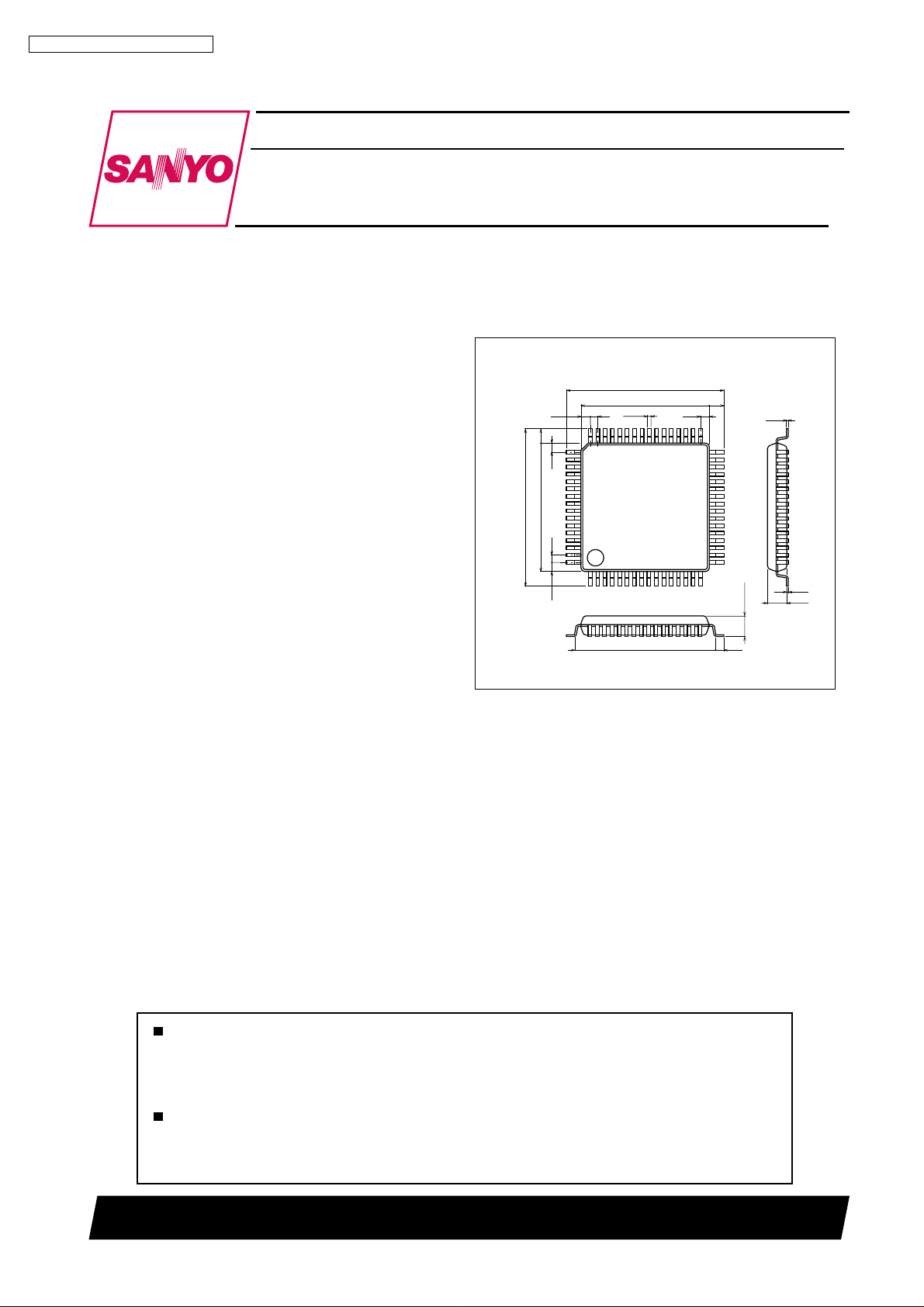
Package Dimensions
unit : mm
3231-QIP64G
[LC72348G-9970]
17.2
14.0
0.8
0.35
116
15.6
17.2
1.6
14.0
1.0
49
1.0
0.8
1.0
48
64
1.6
1.0
33
32
17
3.0max
0.8
SANYO : QIP-64G
0.15
0.1
2.15
Any and all SANYO products described or contained herein do not have specifications that can handle
applications that require extremely high levels of reliability, such as life-support systems, aircraft's
control systems, or other applications whose failure can be reasonably expected to result in serious
physical and/or material damage. Consult with your SANYO representative nearest you before using
any SANYO products described or contained herein in such applications.
SANYO assumes no responsibility for equipment failures that result from using products at values that
exceed, even momentarily, rated values (such as maximum ratings, operating condition ranges, or other
parameters) listed in products specifications of any and all SANYO products described or contained
herein.
SANYO Electric Co.,Ltd. Semiconductor Company
TOKYO OFFICE Tokyo Bldg., 1-10, 1 Chome, Ueno, Taito-ku, TOKYO, 110-8534 JAPAN
81000 RM (IM)
No.6633-1/10
Page 2
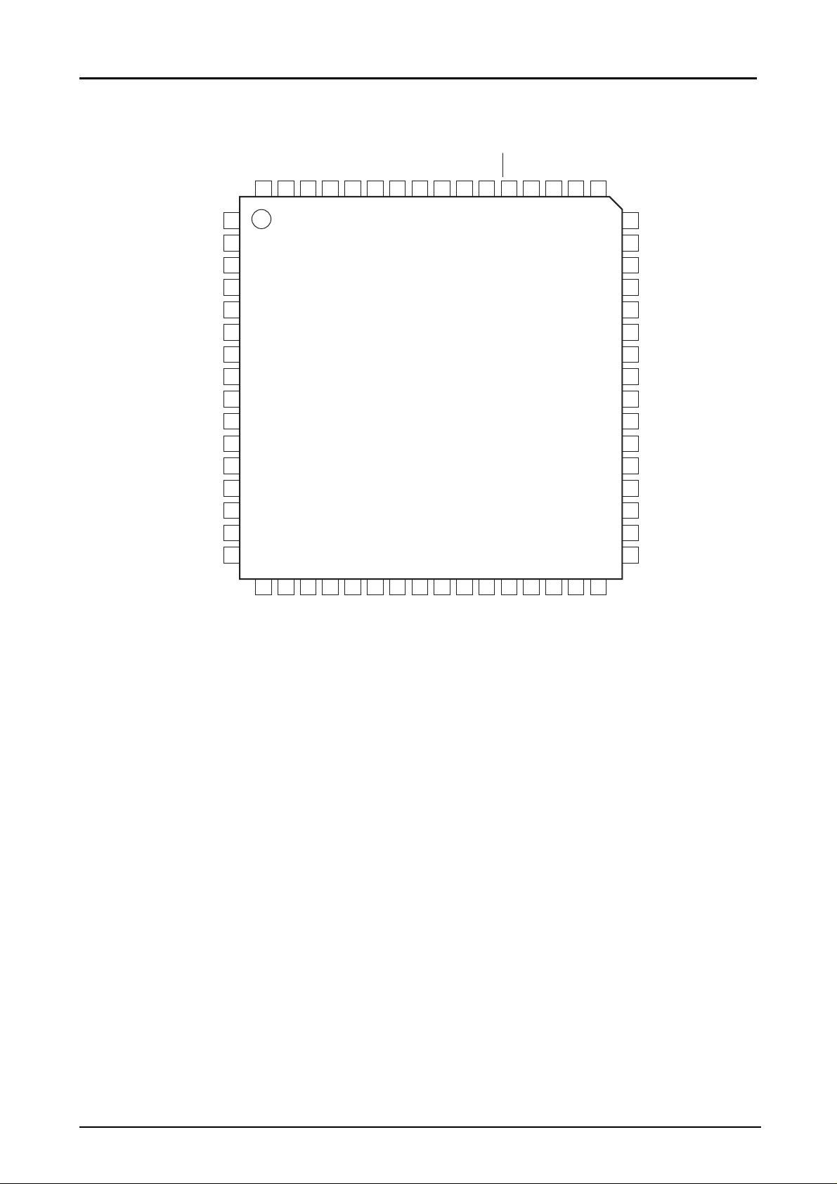
Pin Assignment
LC72348G-9970
XIN63TEST162AGND61AOUT60AIN59EO58VSS57AMIN56FMIN55VDD54TU53RES52DBR151DBR250DBR349DBR4
64
XOUT
TEST2
KEYIN3
KEYIN2
KEYIN1
KEYIN0
KEYOUT3
KEYOUT2
KEYOUT1
KEYOUT0
BAND
FM MN/ST
NC
NC
AREA1
AREA0
1
2
3
4
5
6
7
8
9
10
11
12
13
14
15
16
17
18NC19NC20
TAPE
LC72348G--9970
21
22
23
24
BUZZER
PWR CHECK2
STEREO
PWR CHECK3
VSS
25
POWER
26
27
HOLD
28
MUTE
TUNER OUT
29
SD IN
30
S1531S1432S13
COM1
48
COM2
47
COM3
46
COM4
45
S1
44
S2
43
S3
42
S4
41
S5
40
S6
39
S7
38
S8
37
S9
36
S10
35
S11
34
S12
33
Top view
ILC00004
No.6633-2/10
Page 3
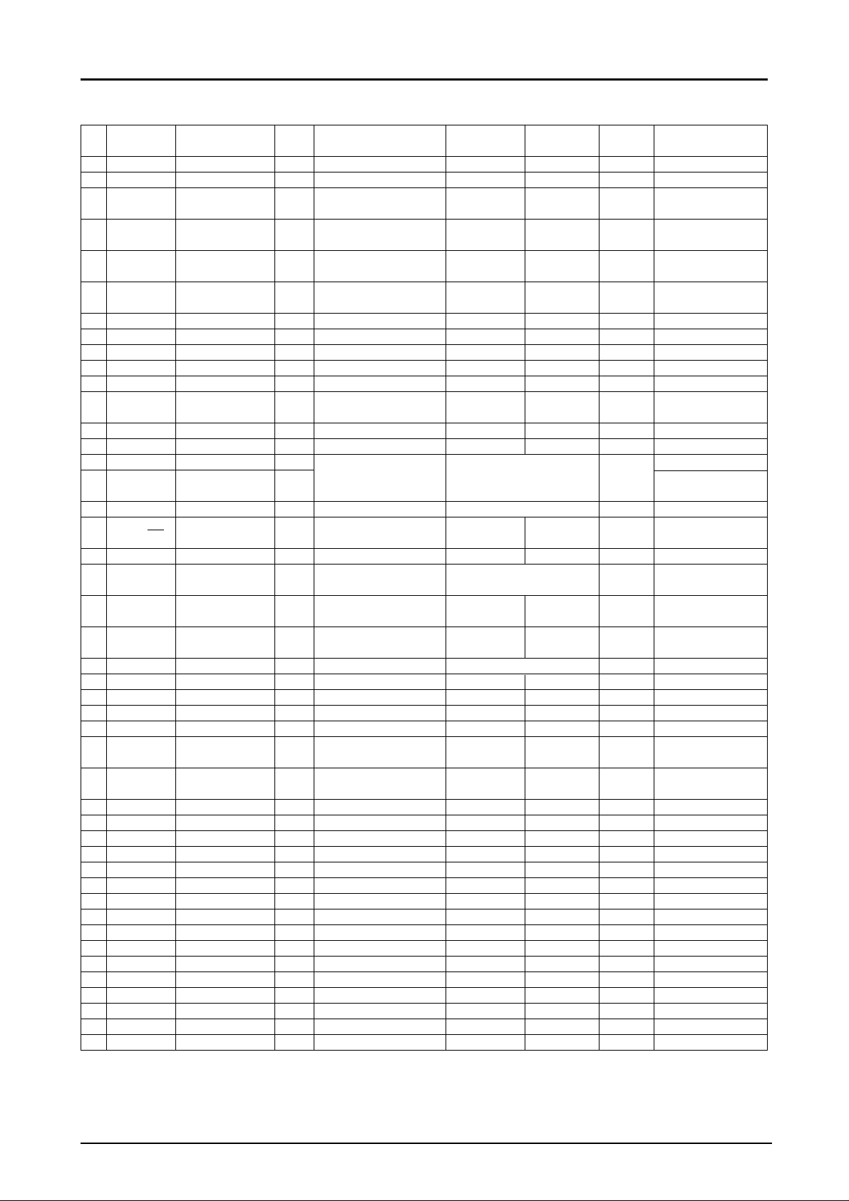
Pin Function
LC72348G-9970
No. Pin name Designation I / O Function description
1 XOUT XOUT OUT Quartz output
2 TEST2 TEST2 IN Connect to GND
3 PA3 KEYIN3 IN Key input
4 PA2 KEYIN2 IN Key input
5 PA1 KEYIN1 IN Key input
6 PA0 KEYIN0 IN Key input
7 PB3 KEYOUT3 OUT Key output Scan Standby “Low”
8 PB2 KEYOUT2 OUT Key output Scan Standby “Low”
9 PB1 KEYOUT1 OUT Key output Scan Standby “Low”
10 PB0 KEYOUT0 OUT Key output Scan Standby “Low”
11 PC3 BAND OUT Band output FM band AM band “Low”
12 PC2 FM MN / ST OUT
13 PC1 NC OUT OPEN
14 PC0 NC OUT OPEN
15 PD3 AREA1 IN See information on *1
16 PD2 AREA0 IN
17 PD1 TAPE IN TAPE input See next page *2 No chattering
18 PD0 / INT NC OUT OPEN
19 PE1 NC OUT OPEN
20 PE0 / BEEP BUZZER OUT Beep output
21 PF2 PWR CHECK2 IN Backup input Normal Backup
22 PF1 / ADI1 PWR CHECK3 IN
23 PF0 / ADI0 STEREO IN STEREO input See next page *4 No chattering
24 VSS VSS Ground pin
25 S20 / PG3 POWER OUT Power output Power off Power on “Hi”
26 S19 / PG2 HOLD IN HOLD key input HOLD off HOLD on No chattering
27 S18 / PG1 MUTE OUT Muting output Muting on Muting off “Low”
28 S17 / PG0 TUNER OUT OUT
29 S16 / PH3 SD IN IN SD input
30 S15 / PH2 S15 OUT Segment output
31 S14 / PH1 S14 OUT Segment output
32 S13 / PH0 S13 OUT Segment output
33 S12 S12 OUT Segment output
34 S11 S11 OUT Segment output
35 S10 S10 OUT Segment output
36 S9 S9 OUT Segment output
37 S8 S8 OUT Segment output
38 S7 S7 OUT Segment output
39 S6 S6 OUT Segment output
40 S5 S5 OUT Segment output
41 S4 S4 OUT Segment output
42 S3 S3 OUT Segment output
43 S2 S2 OUT Segment output
44 S1 S1 OUT Segment output
45 COM4 COM4 OUT Common output
FM MN / ST
(mono / stereo) output key state
Destination area input input combinations
Power check input *3 ADC input
(A / D) select
Tape / radio switching
output
Logical Logical Initial
“High” “Low” state
Key Key not Pull-down
pressed pressed enabled
Key Key not Pull-down
pressed pressed enabled
Key Key not Pull-down
pressed pressed enabled
Key Key not Pull-down
pressed pressed enabled
FM Stereo FM Mono “Low”
given on next page
Normal “Hi”, 2 beep
types
T ape mode Radio mode “Hi”
SD not SD Chattering 20 --
pressed pressed 30 ms
“Hi”
Remarks
FM MN / ST
*1
Pull-down
enabled
No.6633-3/10
Page 4

LC72348G-9970
No. Pin name Designation I / O Function description
46 COM3 COM3 OUT Common output
47 COM2 COM2 OUT Common output
48 COM1 COM1 OUT Common output
49 DBR4 DBR4 OUT
50 DBR3 DBR3 OUT
51 DBR2 DBR2 OUT
52 DBR1 DBR1 OUT
53 RES RES IN Reset input
54 TU TU OUT
55 VDD VDD +3V power supply
56 FMIN FMIN IN FM input
57 AMIN AMIN IN AM input
58 VSS VSS Ground pin
59 E0 E0 OUT Error output
60 AIN AIN IN Low-pass filter input
61 AOUT AOUT OUT Low-pass filter output
62 AGND AGND Connect to GND
63 TEST1 TEST1 IN Connect to GND
64 XIN XIN IN Quartz input
LCD power supply
step-up pin
LCD power supply
step-up pin
LCD power supply
step-up pin
LCD power supply
step-up pin
Tuning voltage generating circuit output
Logical Logical Initial
“High” “Low” state
Remarks
*1 : PD3 (AREA 1), PD2 (AREA 0) inputs
PD3 PD2 Destination area
Hi Low USA
Low Hi Europe
Low Low East Europe
Hi Hi Japan
*2 : PD1 (TAPE) input
Tuner off changes the following functions
Condition PD1 State (display)
Tuner off Hi Tape mode (“TAPE” displayed)
(TAPE input) Low Power off (clock display)
*3 : PF1 / ADI1 (PWR CHECK 3) input
A/D value and operation status are shown below. A/D is read only at power-on.
Input voltage Detection method P-FUL P-MID P-LOW Operation state A / D input value
--2.64V PF1(A / D) Lit Lit Lit Normal 00h-0Eh
2.45V--2.10V PF1(A / D) Out Lit Lit Normal 0Fh-10h
2.09V--1.81V PF1(A / D) Out Out Flashing Normal 11h-15h
1.80V-- PF1(A / D) Out Out Out
PF2 Out Out Out Backup mode
Transition to
radio off
*4: PF0 / ADI0 (STEREO) input
PF0 input switches functions as shown below during Tuner ON.
Condition PF0 State (display)
Tuner ON Hi “FM ST” flashing (when FM band tuning only)
(FM ST input) Low “FM ST” lit (when FM band tuning only)
16h-1Fh
No.6633-4/10
Page 5

LC72348G-9970
Key Operation Description
Key Operation Description
Tuner mode
- Frequency changes upwards by one step when a key is depressed for less than 0.5 second and released. In this case,
a 3.125 kHz buzzer is output.
- Keeping the key depressed for more than 0.5 second changes frequency upwards by one step every 100 ms.
- At the band edge (changeover from maximum frequency to minimum frequency), there is a 500 ms wait.
Up / Hour
Down / Min - Key is inoperative.
Memo 1
Memo 2
Memo 3
Memo 4
Memo 5
T ape mode
- Key is inoperative.
Clock setting mode
- During clock 1 and 2 setting, hour indication changes upwards by one step with each push. Keeping the key depressed for more than
0.5 seconds causes a change by one step every 250 ms, until the key is released.
Alarm setting mode
- During alarm setting, hour indication changes upwards by one step with each push. Keeping the key depressed for more than 0.5
seconds causes a change by one step every 250 ms, until the key is released.
Tuner mode
- Frequency changes downwards by one step when a key is depressed for less than 0.5 second and released. In this case,
a 3.125 kHz buzzer is output.
- Keeping the key depressed for more than 0.5 second changes frequency downwards by one step every 100 ms.
- At the band edge (changeover from minimum frequency to maximum frequency), there is a 500 ms wait.
T ape mode
Clock setting mode
- During clock 1 and 2 setting, minute indication changes upwards by one step with each push. Keeping the key depressed for more than
0.5 seconds causes a change by one step every 150 ms, until the key is released.
Alarm setting mode
- During alarm setting, hour indication changes upwards by one step with each push. Keeping the key depressed for more than 0.5
seconds causes a change by one step every 150 ms, until the key is released.
Tuner mode
- Serve for preset station recall and store.
- Pressing a key and releasing it within less than 2 seconds calls up the frequency stored in the corresponding preset number (1 -- 10).
Keeping a key depressed for 2 seconds or more writes the currently received frequency to the corresponding preset number (1 -- 10).
- For information on switching between presets 1 -- 5 and 6 -- 10, see the Memo+ key section.
- When recall or store is confirmed, a 1.56 kHz beep corresponding to the preset number is output.
T ape mode
- Keys are inoperative.
Power off mode
- Keeping a key depressed for more than 500 seconds calls up the corresponding clock display for Memo1 or Memo2.
No.6633-5/10
Page 6

LC72348G-9970
Key Operation Description
Tuner mode
- Pressing this key and then one of the Memo1 -- Memo5 keys within 5 seconds causes the preset numbers 6 -- 10 to be called. Pressing
one of the Memo1 -- Memo5 keys after 5 seconds have elapsed or after another key was pressed causes the preset numbers 1 -- 5 to
be called.
- At each push of the key, a 1.56 kHz beep is output for 50 ms.
T ape mode
- Key is inoperative.
Power off mode
- Serves for activating and terminating the clock/alarm setting mode.
Memo+
Clock display Alarm setting mode Clock setting mode
ALARM
Function - Keeping the key depressed for 2 seconds or more while AM band or FM I band is selected switches to Power OFF (TAPE).
FM MN / ST
Initial destination
area setting JP US EU
Key
World area
switching
” Memo + ” + ” Down ” EU EU US
” UP ” + ” Down ” JP US EU
CLOCK Sel
(Diode switch)
ALARM Sel
(Diode switch)
- Keeping the key depressed for at least 1 second causes the following mode change.
- In alarm setting mode, the alarm time is placed in the setting area. During the setting procedure, the DOLBY mark flashes on the
display, regardless of the alarm ON / OFF state.
- Pressing the key again during alarm setting terminates the setting procedure and causes the set time to be placed in the setting area
and serves for clock setting mode. The DOLBY display indication depends on the alarm ON / OFF state.
- In clock setting mode, the time of the currently selected clock number is placed in the setting area.
During the setting procedure, the colon of the time display stops flashing and stays constantly lit, but the clock count continues.
- Pressing the key once more during clock setting cause the currently set time to be placed in the area for the currently selected clock
number. By resetting the minute figures the seconds area is cleared to 00, count restart, and the colon of the time display starts flashing.
- 12-hour notation; colon
24-hour notation; JAZZ, not colon
Tuner mode / tape mode / power off mode
- Alarm ON / OFF key
When alarm is turned ON, DOLBY mark on display is shown.
When alarm is turned OFF, DOLBY mark on display is out.
- Alarm sound is output from BUZZER terminal as 3.125 kHz pulse for 5 minutes. Pressing this key again during alarm output stops the
alarm sound. Last alarm time setting is retained.
- Alarm sound is output in all modes.
- Alarm sound is output to when the displayed time matches the alarm set time regardless of the clocks 1 and 2.
- This key serves for power on / off control and band switching. The operation sequence is as follows.
Power OFF (TAPE) -> AM band -> FM I band -> FM II band -> Power OFF (TAPE).
Releasing the key within less than 2 seconds switches to the next band.
- Power OFF or TAPE is determined by the tape input port.
- This key serves for toggling between FM mono and FM stereo. It is valid in the FM I and FM II bands. FM stereo <--> FM mono.
- When FM stereo is set
When STEREO is ”High”, ”FM STEREO” flashes.
When STEREO is ”Low”, ”FM STEREO” is lit.
- When FM mono is set, ”Low” is output from the FM MN / ST port.
- When no FM band is set, ”Low” is output from the FM MN / ST port.
- This function is available in tuner mode except for the destination area East Europe. To perform switching, the two keys shown in the
table below must be pressed together for 7 seconds or more.
” Memo + ” + ” UP ” US JP --
- When switching is confirmed, and if a different area was selected, preset numbers 1 -- 10 in all bands will be set to the default values for
the new area, and the lowest frequency in the currently selected band is received.
- When switching is confirmed, the following indication is shown for 1 second in the 7-segment display area:
Japan : JP USA : US Europe : EU
- Selects whether clock function is enabled or not.
- During initialization, data are read and the setting is made as follows.
OFF : Clock function enabled (12-hour notation; 2 time settings possible)
ON : Clock function disabled
- Selects whether alarm function is enabled or not.
- During initialization, data are read and the setting is made as follows. If the clock is disabled, the alarm function is also not available.
OFF : Alarm function enabled
ON : Alarm function disabled
No.6633-6/10
Page 7

LC72348G-9970
Key Operation Description
- Selects 12/24-hour display.
12 / 24 Sel
(Diode switch)
LCD Check
(Diode switch)
Key Matrix
* PB3 output line is Diode switch.
* When CLOCK Sel is turned OFF, alarm function enabled can be selected and 12/24-hour display can’t be selected.
Reception Frequencies
Destination area : Japan (A1 = ”High”, A2 = ”High”)
Area BAND Reception Frequency Step
JPN AM 531--1629kHz 9kHz 3kHz +450kHz
USA AM 530--1710kHz 10kHz 5kHz +450kHz
EUR AM 531--1602kHz 9kHz 3kHz +450kHz
- During initialization, data are read and the setting is made as follows. If the clock is disabled, 12/24-hour display is also not available.
OFF : 12-hour display (Initial display : 12:00)
ON : 24-hour display (Initial display : 0:00) JAZZ, not colon
- Selects whether LCD check is performed or not.
- During initialization, data are read and the setting is made as follows.
OFF : LCD check disabled
ON : LCD check enabled
- Display check is performed after reading diode switches. All display elements are turned on for 3 seconds,and the display then switches
to normal operation.
PA0 input PA1 input PA2 input PA3 input
PB0 output Up / Hour Down / Min FM MN / ST Memo1
PB1 output Memo2 Memo3 Memo+ / Time set Memo5
PB2 output FUNC ALARM Memo4
PB3 output Clock Sel ALARM Sel 12/24 Sel LCD Check
Reference Intermediate
frequency frequency
FM I 76.0--90.0 / 90.0--108.0MHz 100 / 50kHz 12.5kHz --10.7MHz
FM II 76.0--90.0 / 90.0--108.0MHz 100 / 50kHz 12.5kHz --10.7MHz
FM I 87.5--108.1MHz 200kHz 12.5kHz --10.7MHz
FM II 87.5--108.1MHz 200kHz 12.5kHz --10.7MHz
FM I 87.5--108.0MHz 50kHz 12.5kHz --10.7MHz
FM II 87.5--108.0MHz 50kHz 12.5kHz --10.7MHz
Destination area : USA (A1 = ”High”, A2 = ”Low”), Europe (A1 = ”Low”, A2 = ”High”)
Area BAND Reception Frequency Step
JPN AM 531--1629kHz 9kHz 3kHz +450kHz
FM I 76.0--90.0 / 90.0--108.0MHz 100 / 50kHz 12.5kHz +10.7MHz
FM II 76.0--90.0 / 90.0--108.0MHz 100 / 50kHz 12.5kHz +10.7MHz
USA AM 530--1710MHz 10kHz 5kHz +450kHz
FM I 87.5--108.1MHz 200kHz 12.5kHz +10.7MHz
FM II 87.5--108.1MHz 200kHz 12.5kHz +10.7MHz
EUR AM 531--1602kHz 9kHz 3kHz +450kHz
FM I 87.5--108.0MHz 50kHz 12.5kHz +10.7MHz
FM II 87.5--108.0MHz 50kHz 12.5kHz +10.7MHz
Reference Intermediate
frequency frequency
Destination area : East Europe (A1 = ”Low”, A2 = ”Low”)
Area BAND Reception Frequency Step
AM 531--1602kHz 9kHz 3kHz +450kHz
EAST EUR FM I 65.0--74.0MHz 10kHz 5kHz +10.7MHz
FM II 87.5--108.0MHz 50kHz 12.5kHz +10.7MHz
Reference Intermediate
frequency frequency
No.6633-7/10
Page 8

LC72348G-9970
Initial Reception Frequencies
Area : Japan
12345678910
AM 531 630 999 1440 1629 531 630 999 1440 1629
FM I 76.00 80.00 90.00 100.00 108.00 76.00 80.00 90.00 100.00 108.00
FM II 76.00 80.00 90.00 100.00 108.00 76.00 80.00 90.00 100.00 108.00
Area : USA
12345678910
AM 530 630 1000 1440 1710 530 630 1000 1440 1710
FM I 87.50 93.10 98.10 103.10 108.10 87.50 93.10 98.10 103.10 108.10
FM II 87.50 93.10 98.10 103.10 108.10 87.50 93.10 98.10 103.10 108.10
Area : Europe
12345678910
AM 531 630 999 1440 1602 531 630 999 1440 1602
FM I 87.50 93.10 98.10 103.10 108.00 87.50 93.10 98.10 103.10 108.00
FM II 87.50 93.10 98.10 103.10 108.00 87.50 93.10 98.10 103.10 108.00
Area : East Europe
12345678910
AM 531 630 999 1440 1602 531 630 999 1440 1602
FM I 65.00 67.00 70.00 72.00 74.00 65.00 67.00 70.00 72.00 74.00
FM II 87.50 93.00 98.00 103.00 108.00 87.50 93.00 98.00 103.00 108.00
* AM band unit : kHz, FM band unit : MHz
LCD Panel Description
LCD Matrix
segment PIN No. COM1 COM2 COM3 COM4
S1 44 Low AM(1) FM I FM II
S2 43 Mid T mark 1 mark
S3 42 1a 1f 1g 1e
S4 41 colon 1b 1c 1d
S5 40 Full 2f 2e
S6 39 2a 2g 2d
S7 38 HOLD 2b 2c JAZZ
S8 37 TUNED 3f 3e dot mark
S9 36 3a 3g 3d
S10 35 AM(2) 3b 3c
S11 34 PM 4f 4e
S12 33 4a 4g 4d DOLBY
S13 32 pre 1 4b 4c PRESET
S14 31 5a 5f 5g 5e
S15 30 FM STEREO 5b 5c 5d
*JAZZ mark is used to the colon of the 24-hour display.
*DOLBY mark is used to display the ALARM on / off state.
LCD Panel
HOLD TUNED
AM PM FM STEREO
AM
FMI
FMII
JAZZ
Low Mid Full
PRESET
ILC00002
No.6633-8/10
Page 9

Sample Application Circuit
LC72348G-9970
+3V
100µH
FM OSC
AM OSC
12V
2.7kΩ
VT
+
+
10µF
0.1µF
0.47µF
0.1µF
33kΩ
+
470µF
100pF
100pF
10kΩ
100kΩ
1 2 3 4 5 6 7 8 9 10 11 12 13 14 15 16
S2S3S4S5S6S7S8S9S10
S1
COM4
COM3
COM2
COM1
48
47 46 45 44 43 42 41 40 39 38 37 36 35 34 33
DBR4
49
DBR3
50
DBR2
51
DBR1
RES
TU
VDD
FMIN
AMIN
VSS
EO
AIN
AOUT
AGND
TEST1
XIN
75kHz
X'tal
52
53
54
55
56
57
58
59
60
61
62
63
64
1
2 3 4 5 6 7 8 9 10 11 12 13 14 15 16
XOUT
TEST2
KEY1N3
KEY1N2
KEY1N1
KEY1N0
KEYOUT3
KEYOUT2
KEYOUT1
KEYOUT0
BAND
FM MN / ST
10µF
+
+
NC
S11
NC
AREA1
17 18 19 20
S12
S13
32
S14
31
S15
30
SD IN
29
TUNER OUT
28
MUTE
27
HOLD
26
POWER
25
VSS
24
STEREO
23
PWR CHECK3
22
PWR CHECK2
21
BUZZER
20
NC
19
18
NC
TAPE
17
AREA0
1.5kΩ
680k
1MΩ
47kΩ
330kΩ
HOLD
SW
680k
OFF
ON
11pF 11pF
LCD
Check
M4
M5
M1
or
12/24
Sel
M+
FM
MN/S
R1 33
R1 33
R1 33
BUZZER
R1 33
MUTE
STEREO IN
VCC
SD IN
TUNER OUT
AREA1 AREA0 Area
R2 R3
East Europe
ALARM
CLOCK
Sel
Sel
FUNC
ALARM
M3
M2
Down
Up
/Min
/Hour
T
VT
BAND
FM OSC
AM OSC
TAPE+B
FM MN / ST
R2 R4 Europe
R1 R3 USA
R1 R4 Japan
ILC00005
No.6633-9/10
Page 10

LC72348G-9970
Specifications of any and all SANYO products described or contained herein stipulate the performance,
characteristics, and functions of the described products in the independent state, and are not guarantees
of the performance, characteristics, and functions of the described products as mounted in the customer's
products or equipment. To verify symptoms and states that cannot be evaluated in an independent device,
the customer should always evaluate and test devices mounted in the customer's products or equipment.
SANYO Electric Co., Ltd. strives to supply high-quality high-reliability products. However, any and all
semiconductor products fail with some probability. It is possible that these probabilistic failures could
give rise to accidents or events that could endanger human lives, that could give rise to smoke or fire,
or that could cause damage to other property. When designing equipment, adopt safety measures so
that these kinds of accidents or events cannot occur. Such measures include but are not limited to protective
circuits and error prevention circuits for safe design, redundant design, and structural design.
In the event that any or all SANYO products(including technical data,services) described or
contained herein are controlled under any of applicable local export control laws and regulations,
such products must not be exported without obtaining the export license from the authorities
concerned in accordance with the above law.
No part of this publication may be reproduced or transmitted in any form or by any means, electronic or
mechanical, including photocopying and recording, or any information storage or retrieval system,
or otherwise, without the prior written permission of SANYO Electric Co. , Ltd.
Any and all information described or contained herein are subject to change without notice due to
product/technology improvement, etc. When designing equipment, refer to the "Delivery Specification"
for the SANYO product that you intend to use.
Information (including circuit diagrams and circuit parameters) herein is for example only ; it is not
guaranteed for volume production. SANYO believes information herein is accurate and reliable, but
no guarantees are made or implied regarding its use or any infringements of intellectual property rights
or other rights of third parties.
This catalog provides information as of August, 2000. Specifications and information herein are subject to
change without notice.
No.6633-10/10
PS
 Loading...