

Page 1

Any and all SANYO products described or contained herein do not have specifications that can handle
applications that require extremely high levels of reliability, such as life-support systems, aircraft’s
control systems, or other applications whose failure can be reasonably expected to result in serious
physical and/or material damage. Consult with your SANYO representative nearest you before using
any SANYO products described or contained herein in such applications.
SANYO assumes no responsibility for equipment failures that result from using products at values that
exceed, even momentarily, rated values (such as maximum ratings, operating condition ranges,or other
parameters) listed in products specifications of any and all SANYO products described or contained
herein.
CMOS IC
EPROM-Mountable Type 4-bit Microcomputer
Evaluation Chip for The LC665XX Series
Microcomputers
Ordering number:ENN2648
LC66PG5XX
SANYO Electric Co.,Ltd. Semiconductor Company
TOKYO OFFICE Tokyo Bldg., 1-10, 1 Chome, Ueno, Taito-ku, TOKYO, 110-8534 JAPAN
Overview
The LC66PG5XX is an EPROM-mountable type 4-bit microcomputer for developing and evaluating programs written for the CMOS 4-bit single-chip LC665XX series microcomputers. Either 2764 or 27128 type EPROM can be
mounted on the LC66PG5XX. The LC66PG5XX with the
EPROM mounted can carry out the same functions as those
of the LC665XX series microcomputers. Therefore, you
can evaluate programs developed for application products
controlled by the LC665XX series microcomputers by incorporating the LC66PG5XX into the applications before
the programs are masked in the ROMs.
Features
• Either 2764 or 27128 type EPROM can be mounted.
• Shrink type 64-pin configuration compatible with the
LC665XX series microcomputers. Note that pull-up resistors need to be externally added.
• Options provided for selecting functions.
Options allowing the user to select output signal lev el for
ports 0, 1 and 8 at the initial reset or to specify whether
the watchdog timer function is employed by setting external pin levels
• Instruction cycle time 0.92 to 10 microseconds.
• +5V single power source.
Pin assignment
The LC66PG5XX has the 28-pin soket and 14-pin soket
on the top face of the package. It also has the shrink type
64-pin terminals on the bottom face of the package. The
28-pin soket is used for mounting the EPROM containing
the programs and 14-pin soket for selecting functions by
options (input/output options not included). The shrink type
64-pin terminals are compatible with the LC665XX series
microcomputers.
N3001TN (KT)/7317KI, TS No.2648–1/14
Page 2

LC66PG5XX
Configurations of the LC665XX series microcomputers
emanledoMA60566CLA80566CLA21566CLA61566CLXX5GP66CL99566CL
yticapacMORBK6BK8BK21BK61
yticapacMAR215 4× 215 4× 215 4× 215 4× 215 4× 215 4×
egakcaP
skrameRelbaliavA
S46PID
46PLF
←←←
←←←
.setybK61
deddayllanretxE
S46CID021AGP
kcabyggiPpihcAVE
Notes on use
The LC66PG5XX is a product for developing and evaluating programs for the LC665XX series microcomputers. Keep
always in mind the following considerations when using the LC66PG5XX.
1. The operating conditions are different from those of the production mask ROM . It is not recommended that the
LC66PG5XX is used under the environmental conditions including high temperature and terrible humidity.
2. The electric characteristics are not the same as those of the production mask ROM. To evaluate strictly the electric
characteristics at the interface with external circuits, use the recommended electric characteristics values of the production mask ROM.
3.The discrepancy in internal circuit pattern configuration between the LC66PG5XX and the production mask ROM
results in the following differences between them.
•Differrent initial values are set in RAMs at power ON.
•Differrent noise figures (NF) are recorded. That is, the static noise intensity of the LC66PG5XX is dif ferent from that
of the production mask ROM. Keep it always in mind.
.setybK61
deddayllanretxE
External dimension
No.2648–2/14
Page 3

Overview of terminal function
Terminal
name
P01
P02
P03
output
I/OP00
Input/output port P00 to P03
•Data input and output in 4-bit units or in 1bit units.
•P00 to P03 used for controlling HALT mode.
LC66PG5XX
FunctionInput/
LC66PG5XX output
format
•Nch OD output •Pull-up MOS or Nch OD
Option
(production chip)
(open drain) output
•Output level at initial
reset
At initial
reset
H or L
(optional)
P11
P12
P13
P21/SO0
P22/SCK0
P23/INT0
P31/POUT0
P32/POUT1
Input/output port P10 to P13
I/OP10
•Data input and output in 4-bit units or in 1bit units.
Input/output port P20 to P23
I/OP20/SI0
•Data input and output in 4-bit units or in 1bit units.
•P20 also used as SI0 terminal for serial
input.
•P21 also used as SO0 for serial output.
•P22 also used as SCK0 for serial clock
signal input/output.
•P23 also used as INT0 terminal for INT0
interrupt request input . In addition, it is
used for timer 0 event count input and pulse
width measurement input.
Input/output port P30 to P32
I/OP30/INT1
•Data input and output in 3-bit units or in 1bit units.
•P30 also used as INT1 terminal for INT1
interrupt request signal.
•P31 also used for burst pulse signal output
from timer 0.
•P32 also used for burst pulse signal output
from timer 1 and PWM signal output.
•Nch OD output •Pull-up MOS or Nch OD
output
•Output level at initial
reset
•Nch OD output •CMOS or Nch OD
output
•Nch OD output •CMOS or Nch OD
output
H or L
(optional)
H
H
P41
P42
P43
HOLD mode control input.
IP33/HOLD –––
•When HOLD=L, HOLD mode to be set by
the HOLD instruction.
•During HOLD mode "ON", restart up to the
CPU by applying "H"-level signal to the
HOLD terminal.
•Also used as input port P33 if used together
with port P30 to P32.
•CPU not to be reset even if "L"-level signal
is applied to the RES terminal with the
P33/HOLD set to "L". The output level of the
P33/HOLD terminal at power ON must not
be set "L"on your application products.
I/OP40
Input/output port P40 to P43
•Data input and output in 4-bit units and 1-bit
units.
•Also used for data input/output in 8-bit units
if jointly used with port P50 to P53.
•Used for ROM data output in 8-bit units if
jointly used with port P50 to P53.
•Nch OD output •Pull-up MOS or Nch OD
output
H
Continued on next page
No.2648–3/14
Page 4

Continued from preceding page
Terminal
name
Input/
output
Function
LC66PG5XX
LC66PG5XX output
format
Option
(production chip)
At initial
reset
P51
P52
P53
P61/SO1
P62/SCK1
P63/PIN1
P71
P72
P73
P80
P81
P82
P83
Input/output port P50 to P53
I/OP50
•Data input/output in 4-bit units and 1-bit
unit.
•Used for input/output in 8-bit units if jointly
used with port P40 to P43.
•Used for ROM data output in 8-bit units if
jointly used with port P40 to P43.
Input/output port P60 to P63
I/OP60/SI1
•Data input/output in 4-bit units and 1-bit
units.
•P60 terminal also used as terminal SI1 for
serial input.
•P61 terminal also used as terminal SO1 for
serial output.
•P62 terminal also used as terminal SCK1
for serial clock signal input/output.
•P63 terminal also used for event count input
to timer 1.
Output port P70 to P73
OP70
•Data output in 4-bit units and in 1-bit units.
•The contents of output latch circuit to be
input with input-related instructions.
O
Output port P80 to P83
•Data output in 4-bit units and in 1-bit units.
•The contents of output latch circuit to be
input with input-related instructions.
•Pch OD output option available.
•Nch OD output •Pull-up MOS or Nch OD
output
•Nch OD output •CMOS or Nch OD
output
•Nch OD output •Pull-up MOS or Nch OD
output
•Pch OD output •CMOS or Pch OD
output
•Output level at the initial
reset
H
H
H
H or L
(optional)
P91/INT3
P92/INT4
P93/INT5
PA1
PA2
PA3
PB1
PB2
PB3
I/OP90/INT2
Input/output port P90 to P93
•Data input and output in 4-bit units and in 1bit units.
•P90 also used as the INT2 terminal for INT2
interrupt request input.
•P91 also used as the INT3 terminal for INT3
interrupt request input.
•P92 also used as the INT4 terminal for INT4
interrupt request input.
•P93 also used as the INT5 terminal for INT5
interrupt request input.
Output port PA0 to PA3
OPA0
•Data output in 4-bit units and in 1-bit units.
•The contents of output latch circuit to be
input with input-related instructions.
Output port PB0 to PB3
OPB0
•Data output output in 4-bit units and in 1-bit
units.
•The contents of output latch circuit to be
input with input-related instructions.
•Nch OD output •CMOS or Nch OD
output
•Nch OD output •Pull-up MOS or Nch OD
output
•Nch OD output •Pull-up MOS or Nch OD
output
Continued on next page
H
H
H
No.2648–4/14
Page 5

Continued from preceding page
Terminal
name
PC1
PC2/VREF0
PC3/VREF1
output
I/OPC0
LC66PG5XX
FunctionInput/
Input/output port PC0 to PC3
•Data input and output in 4-bit units and in
1-bit units.
•PC2 also used as the VREF0 terminal for
reference voltage input.
•PC3 also used as the VREF1 terminal for
reference voltage input.
LC66PG5XX output
format
•Nch OD output •CMOS or Nch OD
Option
(production chip)
output
At initial
reset
H
H
PD1/CMP1
PD2/CMP2
PD3/CMP3
PE1/TRB
OSC1
OSC2
IPD0/CMP0
Input port PD0 to PD3
•Can be selected as comparator input
terminals on programs.
PD0 : reference voltage input (VREF0).
PD1 to PD3 : reference voltage input
(VREF1)
•PD0, PD1 (PD2 to PD3) selectable as
comparator input ports on programs in this
unit.
Input port
IPE0/TRA
•Selectable as three-state input port on
programs.
Terminals for system clock oscillator
I
O
externally added.
•Leave OSC2 open and close OSC1 for
external clock signal input when external
clock mode is selected.
IRES
Terminal for system reset signal input.
•CPU to be initialized when P33/HOLD="H"
plus "L" level voltage is applied to the RES
terminal.
ITEST
Terminal for CPU test signal input.
•Always connected to VSS during operation.
– – Normal input
– – Normal input
–
•Ceramic resonator
oscillation, RC (resistor
and capacitor) or
external clock selection.
–
–––
–––
V
DD
V
SS
–
Power source terminal
–––
No.2648–5/14
Page 6

LC66PG5XX special terminals
Terminal
name
P0HL
P1HL
P8HL
output
I
LC66PG5XX
Output typeInput/
–
Terminals for signal input to select output level at ports 0, 1 and 8 at the
reset. "H" level output to be selected if "H" level signal is input to the
terminals.
Function
IRAMC0
RAMC1
IWDC
OCP1 Terminal for signal output to select clock signal edge for output latch of
IIM0 to IM7 Terminals for instruction input from external circuits.
PM0 to PM13 Terminals for PC output to external circuits.
CE Terminal for signal output to contorol the CE terminal of memory
O
O
–
–
Pu MOS output
–
Pu MOS output
Pu MOS output
Terminal for signal input to control RAM capacity.
Terminal for signal input to contorol whether the watchdog timer
function is used. The watchdog timer function to be selected if "H" level
signal is input.
extended ports.
externally added.
Remarks : Pu MOS output ................. Pull-up MOS transistor output.
CMOS output .................... Complementary MOS output.
OD output.......................... Open drain output.
How to mount and use EPROM on the LC66PG5XX
You write assembled program data into an EPROM and mount it on the LC66PG5XX. To write data into the EPROM,
you can use the EPROM writer function of the EVA-800.
No.2648–6/14
Page 7

LC66PG5XX
Power source for EPROM
Normal current drain per EPROM is in the range of 50mA and 100mA. When power capacity of an application product
is not sufficient, power can be supplied to the EPROM from external independent power source. That is, the power source
which is different from that on the application system can be selected.
At the factory shipment, the +5V pin and VDD pin are connected on the LC66PG5XX. Therefore, power is supplied to the
EPROM from the LC66PG5XX power source terminal (pin64).
Of the power source pads on the package surface, +5V pad is used to supply power to the EPROM.
Note
The LC66PG5XX is a CMOS type IC. This reminds us that latch-up may be caused by input voltage le v el belo w the V
SS
level or above the VDD level. The latch-up is specific to this type of IC and destroys IC device structure or adversely
affects operating functions. You should be careful about the voltage level range of the LC66PG5XX and EPROM. To
start the LC66PG5XX and EPROM operation, first turn on the LC66PG5XX and then the EPROM. To stop the
LC66PG5XX and EPROM operation, first turn off the EPROM and then the LC66PG5XX.
Function selection by options
Select the port 0, port 1 or port 8 output level at the reset, watchdog timer function and internal RAM capacity according
to the options and functions of the microcomputer to be evaluated. Set as below pins 1 to 6 of the 14-pin socket on the
package surface.
epytnoitcnuF.oNniPemanniPgnittesniPedomnoitcnuF
dna1trop,0troP
leveltuptuo8troP
teserta
remitgodhctaW6CDW
MARlanretnI
yticapac
1
2
3
4
5
LH0P
LH1P
LH8P
0CMAR
1CMAR
NO"H"leveltuptuotroP
FFO"L"leveltuptuotroP
NOnoitarepO
FFOpotS
gnittesniP
1CMAR0CMAR
FFOFFO
FFONO
yticapacMAR
XX566CLehtrofgnittesoN
sretupmocorcimseires
NOFFO
NONO
W215
ON : +5V voltage input, OFF : Open.
Pins 14, 13, 12, 11, 10 and 9 of the 14-pin socket are assigned as the +5V terminals. These terminals can be used only for
supplying +5V voltage to the pins 1, 2, 3, 4, 5, and 6.
Note that pin 8 is reserved for future use and should be left open.
No.2648–7/14
Page 8

LC66PG5XX
Notes on use
1. The port output format for the LC66PG5XX is as follows : The Pch OD format is employed onl y for port 8. The Nch
OD format is employed for the rest. Add resistors to each port according to the port output formats employed for
production chips.
•When optional pull-up resistors are selected for ports P0, P1, P4, P5, P7, PA and PB, add resistors of about 10kΩ
to them and connect the port to the V
•When the optional CMOS output format is selected for port P8, add the resistor of about 1kΩ to it and connect the
port to the VSS terminal. Select the resistor in the range of 0.5kΩ to 10kΩ according to load balance.
•When the optional CMOS output format is selected for ports P2, P3 (P33 not included), P6, P9 and PC, add the
resistors of about 10 kΩ to them and connect them to the VDD terminal. (add the resistors of more than 1 kΩ if sink
current is used.)
2. The LC66PG5XX has no feedback resistors. Add the external feedback resistor of about 1 MΩ to the LC66PG5XX
when the ceramic resonator oscillation is selected. The external capacitance is the same as that of production chips.
3. The constants and oscillation characteristics of the RC (resistor and capacitor) oscillation circuit are different from
those of production chips. Set them to the oscillation frequency of production chips by making adjustments to volume
resistor.
4. The operating voltage lev el of the LC66PG5XX must be within the range of the operating voltage of the EPROM and
other ICs.
That is, the level is : VDD=5Vwith 5% margin.
5. The operating environment temperature is in the range of 10°C to 40°C.
terminal.
DD
Absolute maximum ratings at Ta = 25˚C, VSS = 0V
retemaraPlobmySetondnalanimreTnoitidnoCsgnitaRtinUetoN
levelegatlovmumixaMV
egatlovtupnI
egatlovtuptuO
lanimretreptnerructuptuO
tnerruclanimretlatoT
noitapissidrewopelbawollAxamdPC°04ot01=aTS46-CID006Wm
erutarepmetgnitarepOrpoT 04+ot01+°C
erutarupmetegarotSgtsT 521+ot55+°C
xamV
DD
VNI1
VNI2rehtOnistupVot3.0–
V
1
TUO
V
2stuptuorehtOVot3.0–
TUO
INO1
INO2BP,AP,7P 02Am3
I–PO28P 4Am4
∑INO1
∑INO2
–∑IPD18 52Am4
DD
,)dedulcnitonDLOH/33P(3P,2P
6P
,)dedulcnitonDLOH/33P(3P,2P
APdna7P,6P
tonDLOH/33P(3P,2P,1P,0P
6P,5P,4P,)dedulcni,8Pdna9P,
CP
,)dedulcnitonDLOH/33P(3P,2P
8Pdna7P,6P,5P,4P
CP,BP,AP,9P,1P,0P 57Am3
0.7+ot3.0–V
0.51+ot3.0–V1
0.3+V2
DD
0.51+ot3.0–V1
0.3+V2
DD
4Am3
57Am3
Note 1: Applicable only when open drain output format is selected. If the format is not selected, another standard value
is used.
Note 2: The self oscillation voltage level can be included in the standard value range as far as oscillation input/output is
concerned.
Note 3: Sink current (applicable to P8 only when CMOS output format is selected).
Note 4: Source current (applicable to terminals other than P8 only when pull-up output format or CMOS output format
is selected).
No.2648–8/14
Page 9
LC66PG5XX
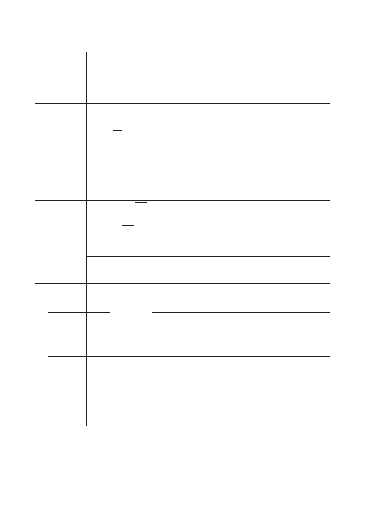
Recomemended operating conditions at Ta = 10˚C to 40˚C, VSS = 0V, unless otherwise specified
TerminalSymbolParameter
Operating power
voltage
Memory hold voltage VDDHV
V
DD
V
DD
DD
HOLD mode
Codnitions Ratings
VDD(V)
min
typ
4.0
5.0
1.8 6.0 V
max
6.0
Unit Note
V
High-level input voltage
Medium-level input
voltage
In-phase input voltage
range
Low-level input voltage
Operating frequency
(instruction cycle time)
Frequency
Pulse width
VIH1 P2, P3 (33/HOLD
not included),P6
VIH2 P33/HOLD P9,
RES, OSC1
VIH3 P0, P1, P4, P5,
PC, PD, PE
VIH4PE
V
IM
V
CMM
VIL1 P2, P3 (33/HOLD
VIL2 P33/HOLD 1.8 to 6.0 V
VIL3 P0, P1, P4, P5,
VIL4PE
fop
(Tcyc)
f
ext
textH
textL
PE 3-state input format 4.0 to 6.0 0.4V
PD, PC2, PC3 Comparator input
not included),P6,
P9, RES, OSC1
PC, PD, PE, TEST
OSC1 See Figure 1.
Output Nch Tr OFF 4.0 to 6.0
Output Nch Tr OFF 4.0 to 6.0 0.75V
Output Nch Tr OFF 4.0 to 6.0 0.7V
3-state input format
mode
Output Nch Tr OFF 4.0 to 6.0 V
Output Nch Tr OFF 4.0 to 6.0 V
3-state input format
Input to the OSC1
terminal. OSC2
terminal left open.
Same as sbove. 4.0 to 6.0 7.0 ns
4.0 to 6.0 0.8V
4.0 to 6.0 1.0 VDD–1.5 V
4.0 to 6.0 V
4.0 to 6.0 0.4
4.0 to 6.0 0.4 4.35 MHz
0.75V
DD
DD
DD
DD
DD
SS
SS
SS
SS
(10)
+13.5 V 1
V
V2
DD
V
V
DD
V
V
DD
0.6V
0.25V
0.25V
0.3V
0.2V
(0.92)
DD
DD
DD
DD
DD
4.35
V
V
V
V
V
MHz
(µs)
3
2
3
Fall/rise time
Externanl clock pulse input
condition
Frequency
Oscillation
stabilization
time
oscillation
Ceramic resonator
External RC
Self osillation conditions
oscillation
constants
textR
textF
f
CF
f
CFS
Cext
Rext
Same as sbove. 4.0 to 6.0 30 ns
OSC1, OSC2 See Figure 2. 4.0 to 6.0 4.0
See Figure 3. 4.0 to 6.04MHz 10 ms
OSC1, OSC2 See FIgure 4. 4.0 to 6.0 pF
4MHz MHz
100
2.2
Note 1: Applicable to terminals with open drain output format. VIH2 applied to P33/HOLD terminal.
Note 2: Applicable to terminals with open drain output format.
Note 3: VIH4, V
and VIL4 applied when PE is used for 3-state input operation.
IM
kΩ
No.2648–9/14
Page 10

LC66PG5XX
Electric characteristics at Ta = 10˚C to 40˚C, VSS = 0, unless otherwise specified
Codnitions Ratings
VDD(V)
=13.5V
4.0 to 6.0
4.0 to 6.0 +1.0 µA
min typ
High-level input current IIH1
IIH2 P0, P1, P4, P5, P9
TerminalSymbolParameter
P2, P3 (33/HOLD
not included),P6
PC, OSC1, RES,
P33/HOLD (PD,
PE, PC2 and PC3,
not included)
V
IN
Output Nch Tr OFF
V
IN =VDD
Output Nch Tr OFF
max
+5.0
Unit Note
µA
1
1
Low-level input current
High-level output voltage
Low-level output voltage
Output off leak current
Comparator offset
voltage
Hysteresis voltage
High-level
threshold voltage
IIH3 PD, PE, PC2, PC3 VIN=V
Output Nch Tr OFF
IIL1 Input level to
terminals other
than PD, PE, PC2
and PC3
IIL2
VOH1P8
VOL1 P0, P1, P2, P3, P4,
VOL2 P7, PA, PB
I
OFF
I
OFF
I
OFF
V
OFF
V
HYS
VtH
PC2, PC3, PD, PE
P5, P6, P9, and PC
(P33/HOLD not
included)
P2, P3, P6, P7, PA
1
2 (P2, P3, P6, P7, P8
and PA not included)
3
P8
PD VIN=1.0V to
P2, P3, RES, P6,
P9 and OSC1.
OSC1 for external
clock signal input.
VIN=V
Output Nch Tr OFF
VIN=V
Output Nch Tr OFF
IOH= –1mA
IOH= –0.1mA
IOL= 1.6mA
IOL= 10mA
VIN=13.5V 4.0 to 6.0 5.0 µA
VIN=V
VIN=V
VDD–1.5V
DD
SS
SS
DD
SS
4.0 to 6.0 +1.0 µA
4.0 to 6.0 –1.0 µA2
4.0 to 6.0 –1.0
4.0 to 6.0
4.0 to 6.0
4.0 to 6.0 0.4 V
4.0 to 6.0 1.5 V
4.0 to 6.0
4.0 to 6.0
4.0 to 6.0 ±300 mV
4.0 to 6.0
V
DD–1.0
V
DD–0.5
0.5V
–1.0
DD
0.1V
±50
DD
0.75V
1.0
DD
µA
µA
µA
1
2
V
6
6
7
V
Low-level
Schmidt
characteristics
threshold voltage
RC (resistor and
capacitor) oscillation
frequency)
Input
Outnput
Input
Outnput
Input
Outnput
Serial clock
Cycle
time
Low-level/
high-level/
pulse width
Fall/rise
time
VtL 0.25V
f
RC
t
CKCY See the timing shown
t
CKL
t
CKH
t
CKR
t
CKF
OSC1, OSC2 See Figure 4.
Cext=100pF±5%
Rext=2.2kΩ±1%
SCK0, SCK1
in Figure 5 and the
test load in Figure 6.
4.0 to 6.0 2.0 3.0
4.0 to 6.0 µs
4.0 to 6.0
4.0 to 6.0
4.0 to 6.0
4.0 to 6.0
4.0 to 6.0
DD
0.92
2.0
0.4
1.0
0.5V
DD
4.0 MHz
Tcyc
µs
Tcyc
µs
3.0
0.1
Continued on next page
No.2648–10/14
Page 11

Continued from preceding page
Data setup time
Data hold time
Serial inputSerial outputPulse input conditions
t
t
ICK
CKI
TerminalSymbolParameter
SI0, SI1
LC66PG5XX
Codnitions Ratings
See Figure 5 "Serial
input/output timing"
Synchronized with the
rise (↑) of the SCK0
and SCK1 signals.
VDD(V)
4.0 to 6.0
4.0 to 6.0 µs
min typ
0.3
0.3
max
Unit Note
µs
Output delay time
INT0 high-level/
low-level/pulse
width
Interrupt input to
terminals other
than INT0. Highlevel/low-level/
pulse width.
PIN1 high-level/
low-level/pulse
width
RES high-level/
low-level/pulse
width
t
CKO
t
I0H
t
I0L
t
I1H
t
I1L
t
PINH
t
PINL
t
RSH
t
RSL
SO0, SO1
INT0
INT1, INT2
INT3, INT4
INT5
PIN1
RES
See Figure 5 "Serial
input/output timing"
and Figure 6 "Timing
load". Synchronized
with the fall (↓) of the
SCK0 and SCK1
signals.
•When INT0 interrupt
See
is accepted.
Figure
•When timer 0 event
7.
counter/pulse width
measure input is
accepted.
•When each interrupt
is accepted.
•When timer 1 event
counter input is
accepted.
•When reset signai is
accepted.
4.0 to 6.0
4.0 to 6.0 Tcyc
2
2
2
3
0.3
µs
Tcyc
Tcyc
Tcyc
Comparator response
speed
Operating mode current
drain
HALT mode current
drain
HOLD mode current
drain
T
RS
I
DDop
I
DDHALTVDD
I
DDHOLDVDD
PD
V
DD
See
Figure
8.
4MHz ceramic
resonator oscillation
4MHz external clock
RC oscillation
4MHz ceramic
resonator oscillation
4MHz external clock
RC oscillation
4.0 to 6.0
4.0 to 6.0 4.5 8 mA
4.0 to 6.0 1.0 2.5 mA
1.8 to 6.0 0.01 10 µA
Note 1: Open drain output format and output Nch Tr OFF for input/output common ports.
Note 2: Open drain output format and output Nch Tr OFF for input/output common ports.
Note 6: Open drain output format and output Nch Tr OFF.
Note 7: Open drain output format and output Pch Tr OFF.
Note 8: Reset status. EPROM current drain not included.
Note 9: EPROM current drain not included.
6.5 11
4.0 8
2 3.5
1.2 2.5
30
µs
8
9
9
No.2648–11/14
Page 12
LC66PG5XX
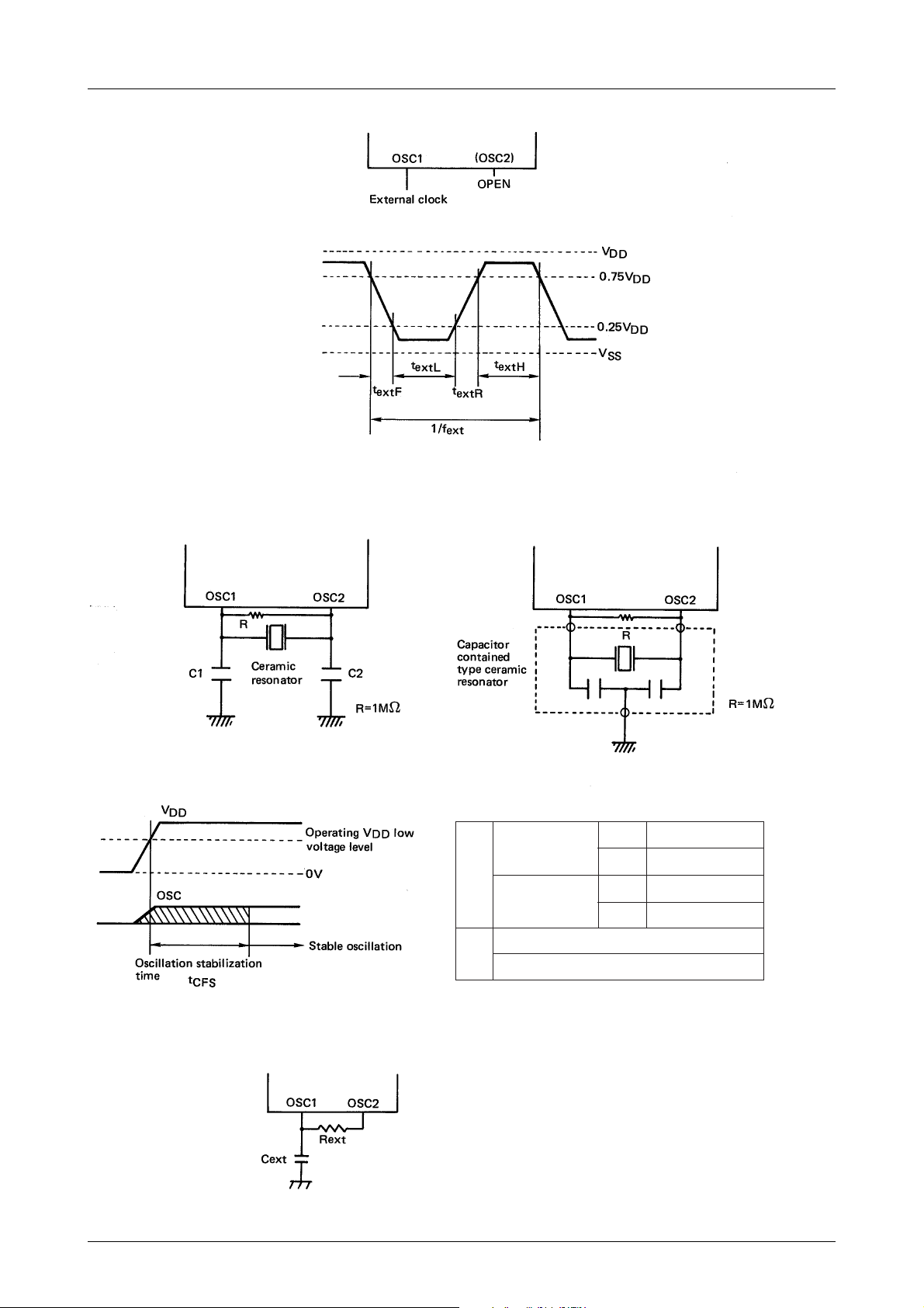
Fig. 1 External clock input waveform
(1) Capacitor externally connected type (2) Capacitor contained type
Fig. 3 Oscillation stable time
Fig. 4 RC oscillation
Fig. 2 Ceramic resonator oscillation circuit
4MHz (Murata)
CSA4.00MG
4MHz (Kyocera)
Capacitor
Capacitor
KBR4.0MS
externally
connected type
contained
type
4MHz CST4.00MG (Murata)
4MHz KBR-4.0MES (Kyocera)
Table1 : Recommended ceramic resonator constants
C1 33pF±10%
C2 33pF±10%
C1 33pF±10%
C2
33pF±10%
No.2648–12/14
Page 13
LC66PG5XX
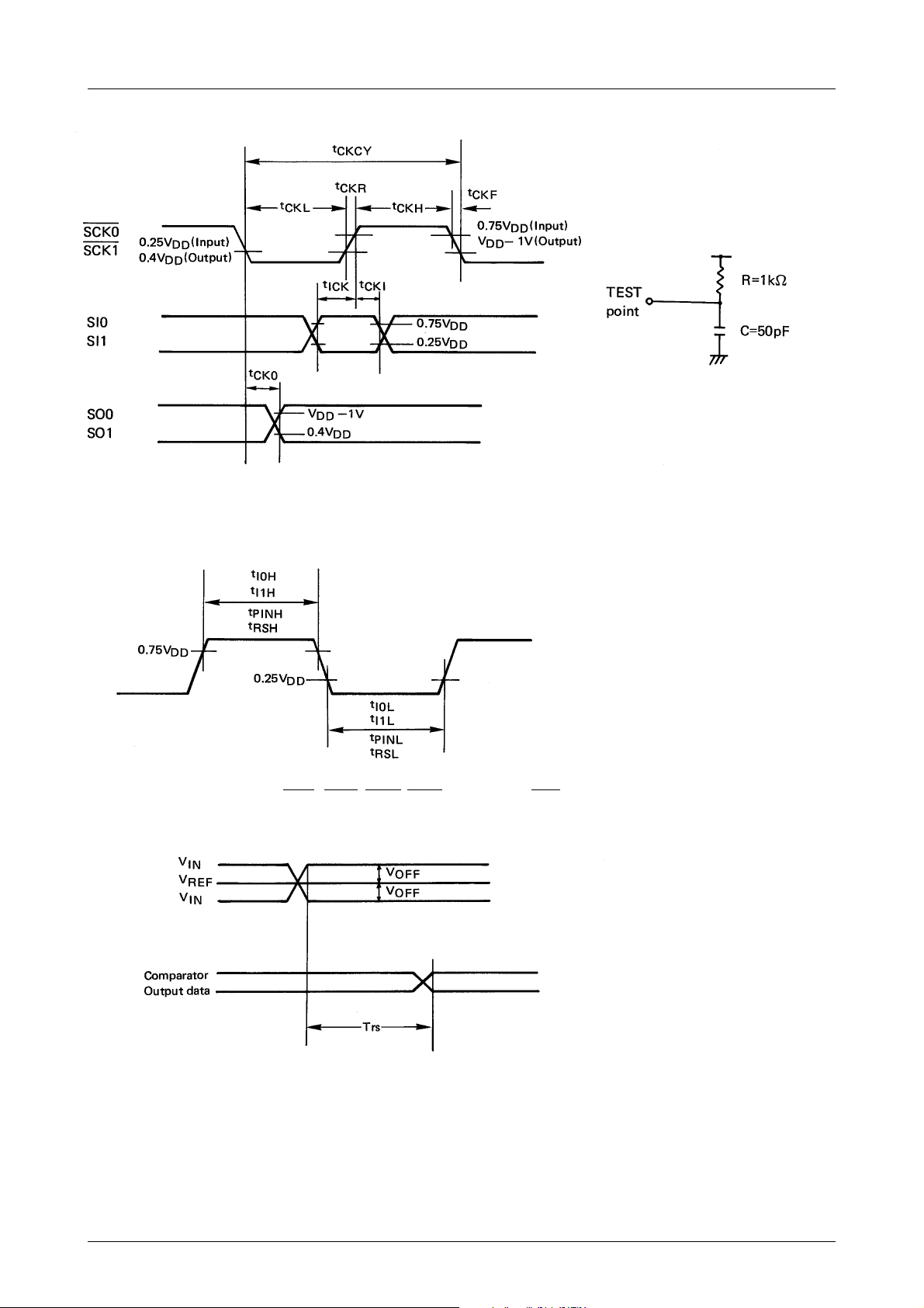
Fig. 5 Serial input/output timing
Fig. 6 Test Loads
Fig. 7 INT0, INT1, INT2, INT3, INT4, INT5, PIN1, RES input timing
Fig. 8 Comparator response Trs timing
No.2648–13/14
Page 14

LC66PG5XX
Specifications of any and all SANYO products described or contained herein stipulate the performance,
characteristics, and functions of the described products in the independent state, and are not guarantees
of the performance, characteristics, and functions of the described products as mounted in the customer's
products or equipment. To verify symptoms and states that cannot be evaluated in an independent device,
the customer should always evaluate and test devices mounted in the customer's products or equipment.
SANYO Electric Co., Ltd. strives to supply high-quality high-reliability products. However, any and all
semiconductor products fail with some probability. It is possible that these probabilistic failures could
give rise to accidents or events that could endanger human lives, that could give rise to smoke or fire,
or that could cause damage to other property. When designing equipment, adopt safety measures so
that these kinds of accidents or events cannot occur. Such measures include but are not limited to protective
circuits and error prevention circuits for safe design, redundant design, and structural design.
In the event that any or all SANYO products(including technical data,services) described or
contained herein are controlled under any of applicable local export control laws and regulations,
such products must not be exported without obtaining the export license from the authorities
concerned in accordance with the above law.
No part of this publication may be reproduced or transmitted in any form or by any means, electronic or
mechanical, including photocopying and recording, or any information storage or retrieval system,
or otherwise, without the prior written permission of SANYO Electric Co. , Ltd.
Any and all information described or contained herein are subject to change without notice due to
product/technology improvement, etc. When designing equipment, refer to the "Delivery Specification"
for the SANYO product that you intend to use.
Information (including circuit diagrams and circuit parameters) herein is for example only ; it is not
guaranteed for volume production. SANYO believes information herein is accurate and reliable, but
no guarantees are made or implied regarding its use or any infringements of intellectual property rights
or other rights of third parties.
This catalog provides information as of November, 2001. Specifications and information herein are subject
to change without notice.
PS No.2648–14/14
 Loading...