

Page 1
Any and all SANYO products described or contained herein do not have specifications that can handle
applications that require extremely high levels of reliability, such as life-support systems, aircraft’s
control systems, or other applications whose failure can be reasonably expected to result in serious
physical and/or material damage. Consult with your SANYO representative nearest you before using
any SANYO products described or contained herein in such applications.
SANYO assumes no responsibility for equipment failures that result from using products at values that
exceed, even momentarily, rated values (such as maximum ratings, operating condition ranges,or other
parameters) listed in products specifications of any and all SANYO products described or contained
herein.
CMOS IC
4-Bit Microcomputer
with Internal LCD Driver
Ordering number:ENN2058A
LC5812
SANYO Electric Co.,Ltd. Semiconductor Company
TOKYO OFFICE Tokyo Bldg., 1-10, 1 Chome, Ueno, Taito-ku, TOKYO, 110-8534 JAPAN
Overview
The LC5812 series models are 4-bit, single-chip, high-performance microcomputers equipped with LCD drivers.
They are produced by CMOS technology. Their numerous
features include low-voltage operation and low current
drain.
A 4 bit parallel-processing ALU, program memory (R OM),
data memory (RAM), input and output ports, a timer, a clock
generator, and LCD drivers, among other things, are integrated on a single chip.
A set of 134 instructions, including the operation and processing instructions executable in 4-bit units and various
conditional branch instructions and LCD driver data transfer instructions form an easy-to-use and effective instruction system.
In HALT mode the user can readily implement the clock
function during low-power dissipation. To minimize the
current required, overall internal operation is stopped except for the oscillation and frequency divider circuits and
the LCD drivers.
In HOLD mode the operation of the system clock oscillation is stopped so that the current drain becomes much less.
The LC5812 is very useful for controlling electronic tuners, cameras, and other portable devices at low v oltage, with
low power dissipation.
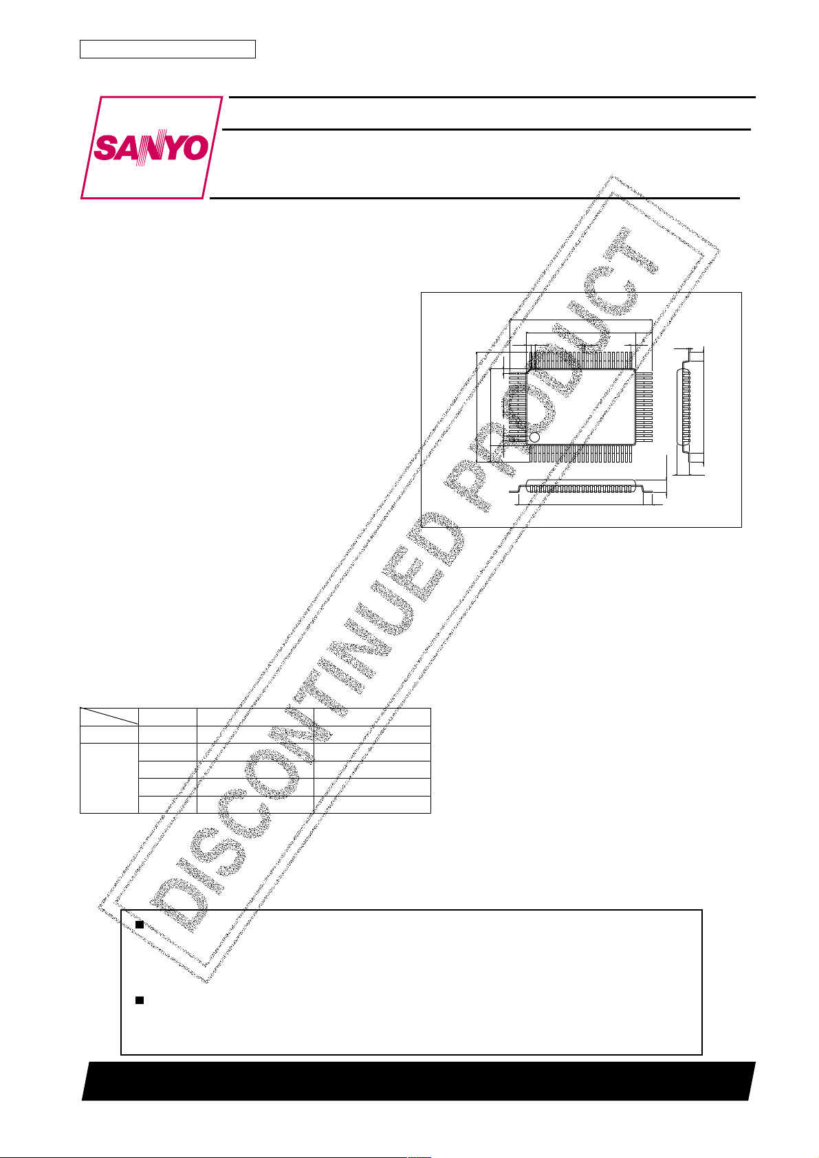
Package Dimensions
unit:mm
3044B-QIP80A
[LC5812]
20.0
14.0
3.0
1.0
0.35
0.8
1.0
26.0
20.0
0.8
0.8
64
65
80
1
0.35
22.6
3.0
0.8
41
24
0.15
2.45max
1.7
16.6
1.7
2.15
40
25
1.7
SANYO : QIP80A
Features
• A wide supply voltage range
emitelcyCegnaregatlovylppuSskrameR
2185CLsµ221V
sµ221V
H2185CL
sµ16V
sµ04V
sµ02V
2SS
2SS
2SS
2SS
2SS
V6.3–ot0.2–=latsyrck23
V0.5–ot0.2–=latsyrck23
V0.5–ot3.2–=latsyrck56
V0.5–ot5.3–=rotanosercimareck004
V0.5–ot5.4–=rotanosercimareck008
Continued on next page.
N3001TN (KT)/3029TA/D1961KI/9115KI, TS No.2058–1/17
Page 2

LC5812
Continued from preceding page.
• Micro-level oprerating current.
Only micro-level current is needed to operate the equipment if the HALT function is used efficiently. Although the
exact current drain depends on the oscillation frequency (and the oscillator) and the program structure, a typical current
requirement is about 5µA to run the clock program if the optimum technique is used to design the program.
• Enhanced HALT/HOLD release and interrupt functions.
· Five types of HALT/HOLD release functions and five types of interrupt functions.
· External interrupt function (included in the above 5 interrupt functions).
· Up to 8 levels of subroutine nesting (common with interrupts).
• Enhanced hardware for greater processing capability.
· Built-in segment PLA circuit : Is able to join the LCD driver outputs to any patterns on the LCD panel without
software.
· Built-in decimal up/down counter.
· Built-in 8-bit programmable timer.
· The entire RAM area can be used as a working area (bank switching).
· Built-in data pointer.
· All instructions per step operation.
· Built-in clock oscillator and frequency divider circuit.
• Various LCD output terminals for LCD panel drive (42 terminals).
lenapDCLstnemgesDCLforebmuN
ytud3/1saib3/1).xam(stnemges621
ytud3/1saib2/1).xam(stnemges621
ytud2/1saib2/1).xam(stnemges48
citatS).xam(stnemges24
• The LCD panel drive output terminal can be switched to the general-purpose output terminal.
• A number of input and output terminals are provided.
Input dedicated port : 2 ports/8 pins
Input/output port : 2 ports/8 pins
Output dedicated port : 1 port/4 pins
• An initial reset terminal is provided.
• Built-in oscillation circuit for system clock.
Two kinds of oscillation circuits are available : one for the system clock and the other for clock oscillation.
• Number of instructions : 134
• ROM : 2,048×16bits
• RAM : 152×4bits
• Form of shipment : QIP80 (or chip)
Application Development Support System
An evaluation chip (LC5897) and special devices for the application development tool will be provided.
• SDS410 system
Enables the user to create an application development program in assembler language (edit-assembling).
• EVA510+TB5812+DCB1+Application Evaluation Board+LC5897
Modification and debugging of the application development program are possible by connecting to the SDS410.
The EVA510 is identical with the EVA410 except that the control ROM has been replaced.
• TB5812+DCB1+Application Evaluation Board+LC5897
Load and evaluation is possible using the EPROM (2732) in which the data for the application development program is
contained.
Note) The application evaluation board is created by the user.
Either LEDs or on LCD can be used as the display element.
Application Examples
• Portable equipment (camera control, various card controls, high-quality electric calculators and timers).
• Acoustic equipment (electronic control, electronic tuning, and clocks).
• Household electrical apparatus (remote control, and timer control).
• Telephone equipment (telephone control, and display control).
No.2058–2/17
Page 3
LC5812
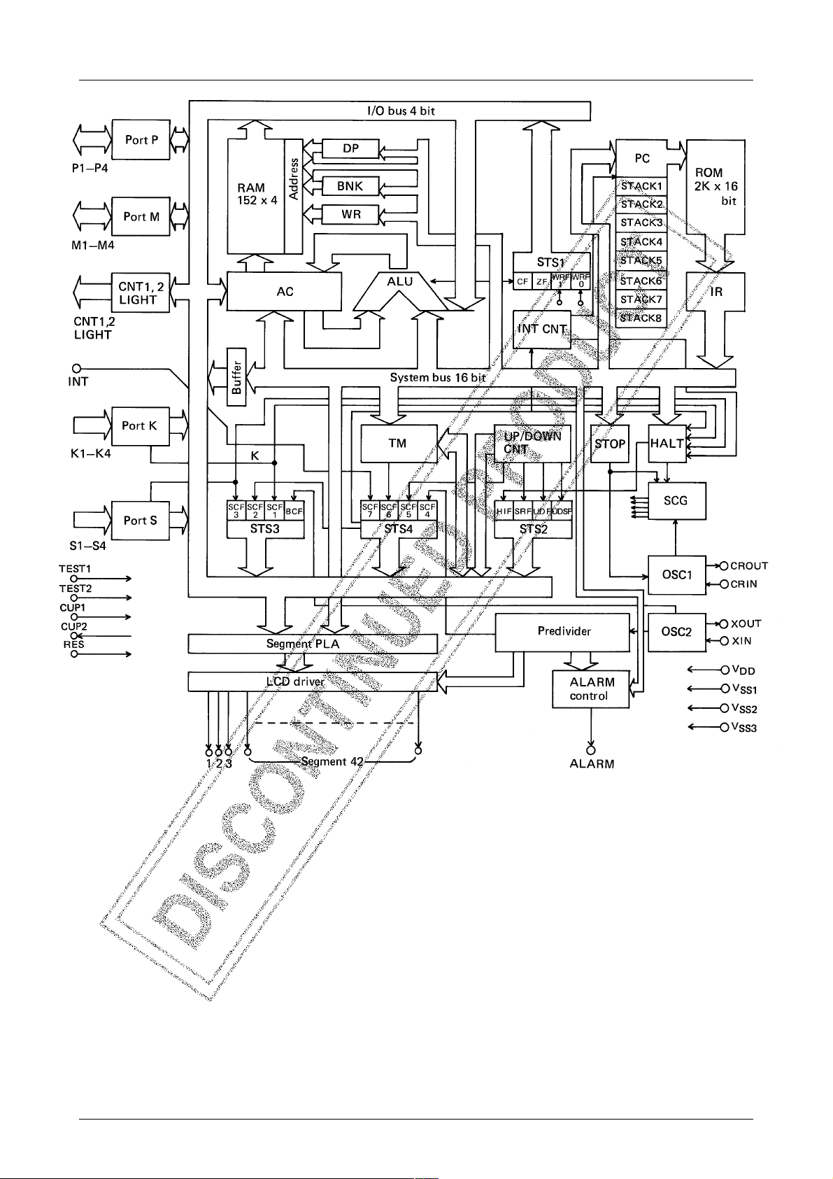
DP : Data pointer STS3 : Status register 3
BNK : Bank register STS4 : Status register 4
WR : Working register CF : Carry flag
AC : Accumulator ZF : Zero flag
ALU : Arithmetic and logical unit WRF0 : Working flag 0
INT : Interrupt control circuit WRF1 : Working flag 1
PC : Program counter BCF : Test flag
UP/DOWN CNT : SCF1 : S port flag
Decimal up/down counter SCF2 : STS4 flag
TIM : Preset timer SCF3 : K port flag
IR : Instruction register SCF4 : Divider overflow flag
STOP : HOLD control circuit SCF5 : UP/DOWN CNT overflow flag
HALT : HALT control circuit SCF6 : Timer overflow flag
SCG : System clock generator SCF7 : INT signal change flag
STS1 : Status register 1 ICF : Internal clock flag
STS2 : Status register 2
No.2058–3/17
Page 4
LC5812
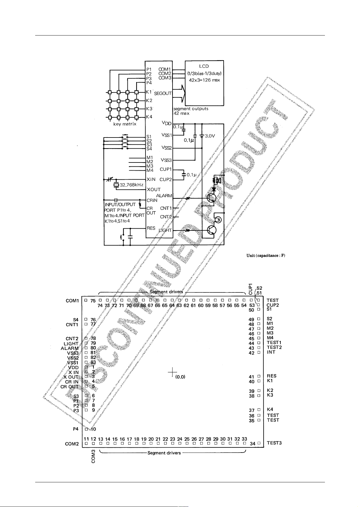
Application Circuit – Example (1/3 bias – 1/3 duty)
Pad Arrangement of IC Chip
Chip size : 7.46mm×5.69mm
Thickness : 480µm
Pad size : 120µm×120µm
No.2058–4/17
Page 5

Pin Layout
Pad name and coordinates
QIP80 pin arrangement
Pad
No.
72
1
10
11
12
13
14
15
16
17
18
19
20
21
22
23
24
25
26
27
28
29
30
31
32
33
34
35
36
37
38
39
40
41
42
2
3
4
5
6
7
8
9
V
X
XOUT
CRIN
CROUT
S3
P1
P2
P3
P4
COM2
COM3
Seg
Seg
Seg
Seg
Seg
Seg
Seg
Seg
Seg
Seg
Seg
Seg
Seg
Seg
Seg
Seg
Seg
Seg
Seg
Seg
Seg
TEST3
TEST
TEST
K4
K3
K2
K1
RES
INT
73
74
75
76
77
78
79
80
1
2
3
4
5
6
7
8
9
10
11
12
13
14
15
16
17
18
19
20
21
22
23
24
25
–
–
26
27
28
29
30
31
Pad
Name
DD
IN
X
(µm)Y(µm)
–3581
–3581
–3581
–3581
–3581
–3581
–3581
–3581
–3581
–3581
–3581
–3367
–2823
–2528
–2233
–1938
–1643
–1347
–1052
– 757
– 462
– 156
+ 150
+ 456
+ 762
+1068
+1374
+1680
+1986
+2292
+2598
+2904
+3210
+3581
+3581
+3581
+3581
+3581
+3581
+3581
+3581
+3581
+ 214
+3
– 176
– 369
– 549
–1048
–1228
–1408
–1588
–2380
–2696
–2696
–2696
–2696
–2696
–2696
–2696
–2696
–2696
–2696
–2696
–2696
–2696
–2696
–2696
–2696
–2696
–2696
–2696
–2696
–2696
–2696
–2696
–2696
–1795
–1584
–1402
–1049
– 868
– 515
– 335
+ 698
QIP80 pin arrangement
Pad
No.
32
43
44
45
46
47
48
49
50
51
52
53
54
55
56
57
58
59
60
61
62
63
64
65
66
67
68
69
70
71
72
73
74
75
76
77
78
79
80
81
82
83
TEST2
TEST1
M4
M3
M2
M1
S2
S1
CUP2
TEST
CUP1
Seg
Seg
Seg
Seg
Seg
Seg
Seg
Seg
Seg
Seg
Seg
Seg
Seg
Seg
Seg
Seg
Seg
Seg
Seg
Seg
Seg
COM1
S4
CNT1
CNT2
LIGHT
ALARM
V
V
V
33
34
35
36
37
38
39
40
–
41
42
43
44
45
46
47
48
49
50
51
52
53
54
55
56
57
58
59
60
61
62
63
64
65
66
67
68
69
70
71
LC5812
Pad
Name
+3581
+3581
+3581
+3581
+3581
+3581
+3581
+3581
+3581
+3581
+3300
+3059
+2764
+2469
+2174
+1878
+1583
+1288
+ 993
+ 687
+ 381
+75
– 231
– 537
– 843
–1149
–1455
–1761
–2067
–2373
–2679
–2985
–3581
–3581
–3581
–3581
–3581
–3581
SS3
SS2
SS1
–3581
–3581
–3581
X
(µm)Y(µm)
+ 878
+1105
+1285
+1465
+1645
+1825
+2005
+2317
+2497
+2696
+2696
+2696
+2696
+2696
+2696
+2696
+2696
+2696
+2696
+2696
+2696
+2696
+2696
+2696
+2696
+2696
+2696
+2696
+2696
+2696
+2696
+2696
+2696
+2101
+1849
+1298
+1114
+ 934
+ 754
+ 574
+ 394
• The values (X, Y) indicate the coordinates of each pad center with the center of the chip as the origin.
• The TEST terminal should be open during normal operation.
• If the chip is used, the substrate must be tied to V
DD
.
No.2058–5/17
Page 6
Pin Function
LC5812
Terminal
X IN Input
X OUT Output
S1
S2
S3
S4
P2
P3
P4
M1
M2
M3
M4
K1
K2
K3
K4
name
Input/
Output
Input
Input/
Output
Input
Circuit
configuration
Connects 32.768kHz or 65.536kHz crystal
between XIN and X
Used for the timer reference clock and system
clock.
X
incorporates a 20pF capacitor to VDD.
OUT
Input-dedicated port.
Has a 7ms or 32ms chatter removal circuit.
By applying VDD to S1 through S4
simultaneously, the internal IC devices are reset
(mask option).
(The chatter removal time is for the 32.768kHz
option.)
I/O port with mode switched by instructions to
perform the following operations :
(1) Input port : Writes data in RAM.
(2) Output port : Outputs data from RAM.
(1) Used to send data to RAM via 7ms or 32ms
chatter removal circuit.
(2) Is able to operate the decimal counter in the
IC circuit with a K2 and K4 signal, according
to instruction.
(The chatter removal time is for the 32.768kHz
option.)
for oscillation.
OUT
(1) For 32K
(2) For 65K
* Option (2) is available only on the
LC5812H.
(1) Selection of L-level Hold Tr.
(2) Use of initial reset by simultaneous
application of VDD to S1 through
S4.
Selection of L-level Hold Tr.
Selection of L-level Hold Tr.
Status during resetFunction Option
Pull-down resistance
is ON during reset.
INT Input
RES Input
CNT1
CNT2
LIGHT Output
Output
Controls the external interrupt request.
(The mask option interlocks with port K.)
Resets the internal IC devices (1) Reset at the H-level
Output-dedicated port (1) "L" output during reset.
Output-dedicated port.
Suitable for outputting the signals which drive the
light transistor.
Selection of L-level Hold Tr.
(with pull-down resistor)
(2) Reset at L-level
(with pull-up resistor)
(2) "H" output during reset.
* Options 1 and 2 can be specified for
each of CNT1 and CNT2.
(1) "L" output during reset.
(2) "H" output during reset.
"L" or "H" output
(according to mask
option).
"L" or "H" output
(according to mask
option).
Continued on next page.
No.2058–6/17
Page 7

Continued from preceding page.
LC5812
Terminal
ALARM Output
V
DD
V
SS3
V
SS2
V
SS1
CUP1
CUP2
COM1
COM2
COM3
Segment
driver
(A group)
Input/
name
Output
Output
Output LCD panel segment output port.
Circuit
configuration
Output-dedicated port.
Is able to output a 4kHz, 2kHz, or 1kHz
modulating signal, according to instruction.
Can also output nonmodulating signals.
(The modulating frequency is for the 32.768kHz
option.)
(+) supply voltage terminal.
V
is a supply terminal.
SS2
V
and V
SS1
power.
Connection terminal for voltage rise (fall)
capacitor.
Output port for common electrodes of LCD panel.
Use of terminals varies.
(The alternating frequency is for the 32.768kHz
option.)
· The terminal can be switched to the output
dedicated port dependeing on the mask option.
· If the internal IC devices are reset, the static
lighting signal is fed to COM1 through COM3 and
to each of the LCD segment outputs, and all LCD
panel segments go on or go off. (on/off : to be
specified by mask option).
· The segment PLA system is used to draw all
patterns on the LCD panel.
are used to supply LCD driving
SS3
citatSytud2/1ytud3/1
1MOC
2MOC –
3MOC ––
gnitanretlA
ycneuqerf
zH23zH23zH34
(1) "L" output during reset.
(2) "H" output during reset.
(1) Lighting specification :
· Static
· 1/2 bias 1/3 duty
· Duplex
· 1/3 bias 1/3 duty
⁄ Output for LCD drive
¤ CMOS output port
‹ Pch open drain output port
Options ⁄, ¤, and ‹ can be selected
in bit units.
Status during resetFunction Option
"L" or "H" output
(according to mask
option).
To be specified by
mask option
⁄ Lighted mode
· Lighted mode
(LCD use)
· H-level (DC use)
¤ Unlighted mode
· Unlighted mode
(LCD use)
· L-level (DC use)
Segment
driver
(B group)
TEST3
TEST
TEST
TEST2
TEST1
TEST
CR IN
CR OUT
Output LCD panel segment output port.
Note) Indicates the connection to V
· The terminal can be switched to the output
dedicated port dependeing on the mask option.
· If the internal IC devices are reset the static
lighting signal is fed to COM1 through COM3 and
to each of the LCD segment outputs, and all LCD
panel segments go on or go off. (on/off : to be
specified by mask option).
· The segment PLA system is used to draw all
patterns on the LCD panel.
Test terminals (the user should not use these
terminals).
CR oscillation port.
The oscillation can be stopped by the HOLD
instruction.
.
SS2
⁄ Output for LCD drive
¤ CMOS output port
Options ⁄ and ¤ can be selected in bit
units.
To be specified by
mask option
⁄ Lighted mode
· Lighted mode
(LCD use)
· H-level (DC use)
¤ Unlighted mode
· Unlighted mode
(LCD use)
· L-level (DC use)
No.2058–7/17
Page 8

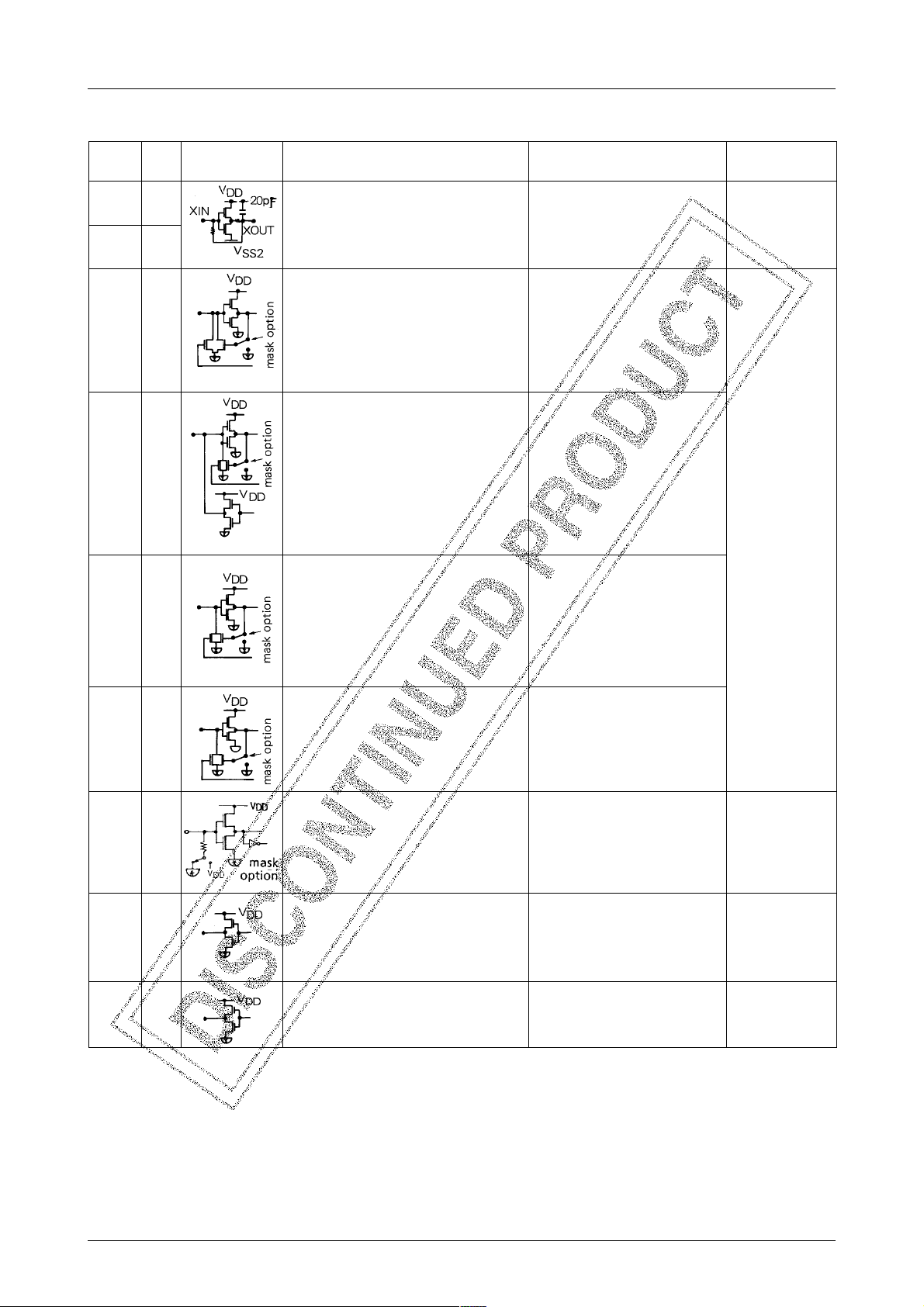
Oscillation Circuit Option
CR & X'tal
Circuit configuration
LC5812
RemarksOption
Cycle time=f1/4
Output from the divider circuit is used as program
timer input signal, LCD drive waveform generating
signal, or interrupt signal generation, etc.
Note) For X'tal=32.768kHz, set Rd=0Ω
CF & X'tal
CR option
Cycle time=f1/16
Output from the divider circuit is used as program
timer input signal, LCD drive waveform generating
signal, or interrupt signal generation, etc.
Note) For X'tal=32.768kHz, set Rd=0Ω
Cycle time=f1/14
Output from the divider circuit is used as program
timer input signal, LCD drive waveform generating
signal, or interrupt signal generation, etc.
Continued on next page.
No.2058–8/17
Page 9

Continued from preceding page.
LC5812
CF option
X'tal option
Circuit configuration
RemarksOption
Cycle time=f1/16
Output from the divider circuit is used as program
timer input signal, LCD drive waveform generating
signal, or interrupt signal generation, etc.
LC5812H only.
Cycle time=f2/4
Output from the divider circuit is used as program
timer input signal, LCD drive waveform generating
signal, or interrupt signal generation, etc.
Note) For X'tal=32.768kHz, set Rd=0Ω
Input Port Option
L-level Hold Tr is
used.
L-level Hold Tr is
not used.
Circuit configuration
· The Hold Tr option is used to reduce the current
required for a push-botton switch for S1, or a slide
switch for S2.
· The L-level signal can be held after the pull-down
resistor is set to ON for a short period of time by
software during the opening of input.
· The pull-down Tr can be used as a pull-down
resistor.
· The pull-down Tr can be set to ON/OFF by
software.
RemarksOption
These options are provided for the S, K, M, and P ports. Be sure to specify NOT USED for the M or P port w hen using it
as an output port.
No.2058–9/17
Page 10

LC5812
LCD Output Options
LCD output options for the LCD drive, the CMOS output port and the Pch open drain can be selected.
Output FormOption
LCD drive
Pch open drain
output port
Alternating waveform for the LCD driver for LCD output is generated by hardware logic.
Segment PLA Circuit
The following figure is a schema of the structure of the segment PLA circuit.
· Terminal for LCD segment drive.
· The drive method is determined according to the LCD lighting system specified separately.
The LCD lighting system is common to all terminals, and can be selected from among the static, duplex, 1/2 bias-1/3 duty,
and 1/3 bias-1/3 duty methods.
· General-purpose CMOS type output port.CMOS output port
· General-purpose Pch open drain type output port.
· Usable according to the PLA option for the predetermined ports.
The contents of data memory are sent to the LCD latch circuit for display either as is or after being decoded by the
data decoder. The PLA circuit is used to rearrange the input data to output it to the display latch. With this circuit , data
memory can be edited to suit LCD panel specifications without software processing. The PLA circuit can be specified
by ROM for PLA, which is supplied with program ROM.
Alarm Output
The following frequency divider output can be used directly as an alarm output :
1) Output signal either as φ3 or φ4 or φ5.
2) Any combination output signal at φ10, φ11, φ12, φ13, φ14 and φ15.
3) Modulating output signal of 1) or 2).
These signals can be output by software.
φN indicates the output at the Nth step of the oscillator frequency divider.
Resetting Internal logic
There are three functions for resetting internal logic :
¡ Built-in power-ON clear circuit
.... Use of this option can be determined by the mask option.
™ Reset terminal RES
£ Simultaneous operation of S1 through S4
.... Use of this option can be determined by the mask option.
No.2058–10/17
Page 11

LC5812
These reset functions are explained below.
1) Built-in power-ON clear circuit
The initial-clear circuit provided in the microcomputer automatically operates and resets internal logic when power
is turned on. This function is very useful in that it can be activated without external devices. But it has the two
disadvantages listed below. It is, therefore, recommended that this function be used with other reset functions, or
that other methods be used according to applications.
Disadvantages :
a) The circuit may not operate under certain power-rise conditions during the power-ON sequence or due to chatter.
b) Malfunctions may take place due to pulse noise in the power or a sudden change in status.
One of the following two reset options can be selected :
INHIBIT : The built-in power-ON clear circuit is not used
.... Use this option where malfunctions due to pulse noise in the power may take place.
NORMAL ACTION : The built-in power-ON clear circuit is used.
.... This option should be selected only when pulse noise does not affect the power.
2) Reset terminal RES
When the reset signal is fed to the reset terminal, the reset flag in the microcomputer is set and part of the divider
circuit is reset. Internal logic is reset by the internal reset flag which is reset by the overflow signal from the divider
circuit. The reset status of the logic circuit is released and the program countner starts operating .
a) with Pull-down R (H-RESET) b) with Pull-up R (L-RESET)
No.2058–11/17
Page 12

LC5812
3) Simultaneous operation of S1 through S4
By applying V
(Use of this option can be specified by the mask option.)
Interrupt Function
• Five factors and four vector addresses are provided for the interrupt function.
– External interrupt terminal (INT)
– Change of signal to port S or K
– Underflow of programmable timer
– Overflow of divider circuit
– Overflow/underflow of decimal UP/DOWN counter
level voltage to S1 through S4 simultaneously, internal logic can be cleared (initial clear).
DD
Same vector address
HALT function
• Can stop the CPU’s system clock in HALT mode with the HALT instruction.
• Reduces the operating current to the oscillation circuit + HALT release signal + LCD drive circuit current during
HALT.
• The following five factors cause HALT release request signals :
– External interrupt terminal (INT)
– Change of signal to port S or K
– Underflow of programmable timer
– Overflow of divider circuit
– Overflow or underflow of decimal UP/DOWN counter
The factors for the HALT release request signal are the same as those for the interrupt request signal, but the use of
any factor can be specified in programs.
If an interrupt occurs in HALT mode, the operation called for by the interrupt is performed, and the CPU returns to
HALT mode.
Release of HALT by Interrupt
No.2058–12/17
Page 13

LC5812
HOLD Function
• Can stop the operation of the oscillation circuit (OSC1) in HOLD mode with the STOP instruction.
• Reduces the current drain to the minimum during HOLD because OSC1 and CPU are stopped.
Relationship between the oscillation options and the HOLD release functions
metI
noitpolat'X&RC
noitpolat'X&FC
noitpoRC
noitpoFC
noitpolat'X
langisteseR
)SER/SER(
×××
: can be used to release HOLD.
× : cannot be used to release HOLD.
Decimal UP/DOWN Counter Function
A hardware function that counts external pulse or the internal reference pulse in decimal notation. One of the following three operations can be selected by software :
¡ The counting of pulses from port K4 with UP and DOWN switched by the signal level of port K2.
™ The counting of pulses from port K4 with UP and DOWN switched by the phase difference signal of port K2.
£ The counting of divider circuit signals of the oscillator in ascending order.
.... With this function, a chrono counter in units of 1/100 second can be implemented by using a 32.768kHz
crystal oscillatior.
tpurretnI
langistseuqer
××
××
××
esaelerTLAH
langistseuqer
etoN
nacnoitcnufDLOH
.desuebton
Open List
2185CLH2185CLskrameR
dohtemgnithgilDCL
)4Sot1S(stropS
stropM
)4Mot1M(
stropK
)4Kot1K(
L-level Hold Tr
tropTNI
)4Pot1P(stropP
noitcelesrotallicsO
noitcnuf
noitceleS
tuptuofo
lanimret
ytiralop
teserno-rewoplanretnI
fonoitareposuoenatlumiS
teserrof4Shguorht1S
ytiralopSERfonoitceleS)nwod-lluP(teserlevel-H
1TNC
2TNC
MRALA
THGIL
citatScitatS
xelpuDxelpuD
ytud3/1saib2/1ytud3/1saib2/1
ytud3/1saib3/1ytud3/1saib3/1
desunUdesunU
.desusirTdloHlevel-L
.desutonsirTdloHlevel-L
.desusirTdloHlevel-L
.desutonsirTdloHlevel-L
.desusirTdloHlevel-L
.desutonsirTdloHlevel-L
.desusirTdloHlevel-L
.desutonsirTdloHlevel-L
.desusirTdloHlevel-L
.desutonsirTdloHlevel-L
LATX&RCLATX&RC
RCLATX&FC
LATXRC
desunU
desU
desU
desunU
)pu-lluP(teserlevel-L
tesergnirudlevel-H
)HlamroN(
tesergnirudlevel-L
)LlamroN(
tesergnirudlevel-H
)HlamroN(
tesergnirudlevel-L
)LlamroN(
tesergnirudlevel-H
)HlamroN(
tesergnirudlevel-L
)LlamroN(
tesergnirudlevel-H
)HlamroN(
tesergnirudlevel-L
)LlamroN(
.desusirTdloHlevel-L
.desutonsirTdloHlevel-L
.desusirTdloHlevel-L
.desutonsirTdloHlevel-L
.desusirTdloHlevel-L
.desutonsirTdloHlevel-L
.desusirTdloHlevel-L
.desutonsirTdloHlevel-L
.desusirTdloHlevel-L
.desutonsirTdloHlevel-L
.ledomeht
FC
LATX
desunU
desU
desU
desunU
)nwod-lluP(teserlevel-H
)pu-lluP(teserlevel-L
tesergnirudlevel-H
)HlamroN(
tesergnirudlevel-L
)LlamroN(
tesergnirudlevel-H
)HlamroN(
tesergnirudlevel-L
)LlamroN(
tesergnirudlevel-H
)HlamroN(
tesergnirudlevel-L
)LlamroN(
tesergnirudlevel-H
)HlamroN(
tesergnirudlevel-L
)LlamroN(
nehw"desunU"tceleS
erastroptuptuoDCLeht
-larenegsadesulla
.stropesoprup
ehtnoFCyficepstonoD
sitiesuaceb,2185CL
noFCesuotdewollaton
No.2058–13/17
Page 14

LC5812
Specifications
Absolute Maximum Ratings at VDD=0V, 1/2bias, 1/2duty
retemaraPlobmySsnoitidnoClanimreTsgnitaRtinU
V
egatlovylppusmumixaM
egatlovtupnimumixaMV
egatlovtuptuomumixaMV
erutarepmetgnitarepOrpoT 07+ot02–
erutarepmetegarotSgtsT 521+ot03–
Allowable Operating Conditions at Ta =–20 to +70˚C, VDD=0V
retemaraPlobmySsnoitidnoClanimreT
egatlovylppusrewoP
egatlovlevel-hgihtupnI
egatlovlevel-woltupnI
ycneuqerfnoitarepO
VSS16.3– 3.1– V
VSS2V
V
V
V
1LI
V
2LI
1SS
V
2SS
1NI
1TUO
V=
2SS
1HI
2HI
1gpofV
2gpofV
2SS
2SS
V
V=
2SS
3SS
3SS
SER
SERV
V6.3–ot0.2–=TUOX/NIX2333zHk
V6.3–ot3.2–=TUORC/NIRC713305zHk
3.0+ot0.4– V
3.0+ot0.4– V
V
2SS
V
2SS
sgnitaR
nimpytxam
6.3– 0.2– V
52.0 ×V
3.0 × V
2SS
2SS
2SS
V
2SS
SERnaht
SERnaht
rehtoslanimrettupnI
rehtoslanimrettupnI
57.0 ×V
7.0 × V
3.0+ot3.0– V
3.0+ot3.0– V
˚C
˚C
tinU
0V
V
V
2SS
V
2SS
Electrical Characteristics at Ta =–20 to +70˚C, VDD=0V
retemaraPlobmySsnoitidnoClanimreT
R
R
ecnatsisertupnI
egatlovlevel-hgihtuptuOV
egatlovlevel-woltuptuOV
egatlovlevel-hgihtuptuOV
egatlovlevel-hgihtuptuOV
egatlovlevel-woltuptuOV
egatlovlevel-hgihtuptuOV
egatlovlevel-hgihtuptuOV
egatlovlevel-woltuptuOV
egatlovlevel-woltuptuOV
egatlovlevel-hgihtuptuOV
egatlovlevel-hgihtuptuOV
egatlovlevel-woltuptuOV
egatlovlevel-woltuptuOV
egatlovlevel-hgihtuptuOV
egatlovlevel-elddimtuptuOV
egatlovlevel-woltuptuOV
egatlovtuptuOV
tnerrucylppusrewoP
R
R
R
IDD
V
A1NI
V
NI
V
B1NI
V
A2NI
V
NI
V
B2NI
V
3NI
V
1HO
I
HO
V
1LO
V
2HO
V
3HO
V
3LO
V
4HO
V
5HO
I
HO
V
4LO
V
5LO
V
6HO
V
7HO
I
HO
V
6LO
V
7LO
V
8HO
V
MO
I
LO
V
8LO
V
1SS
V
,V9.2–=
2SS
V8.0=
2SS
2SS
2SS
2SS
2SS
2SS
2SS
2SS
2SS
2SS
2SS
2SS
2SS
2SS
2SS
2SS
2SS
2SS
2SS
2SS
2SS
2SS
2SS
POTS
V,V9.2–=
=NIVDD
,V9.2–=
V8.0=
2SS
V,V9.2–=
=NIVDD
V9.2–=2TSET,1TSET,SER0108004kΩ
,V4.2–=
Am4.0–=
I,V4.2–=
LO
I,V4.2–=
HO
I,V4.2–=
HO
I,V4.2–=
LO
I,V4.2–=
HO
,V4.2–=
Aµ4.0–=
I,V4.2–=
LO
I,V4.2–=
LO
I,V4.2–=
HO
,V4.2–=
Aµ4.0–=
I,V4.2–=
LO
I,V4.2–=
LO
I,V4.2–=
HO
I,V4.2–=
HO
Aµ4=
I,V4.2–=
HO
V9.2–=
52=aT,V9.2–= ° ,C
sgnitaR
nimpytxam
1.giF
1.giF
1.giF
1.giF
Am4.0=
Aµ09–=Ptrop,MtroP1– 3.0– V
Aµ05–=Ptrop,MtroP6.0– 2.0– V
Am1.0=Ptrop,MtroPV
Aµ02–=tnemgeS1– 3.0– V
Aµ04=V
Aµ4.0=V
Aµ5–=tnemgeS1– 3.0– V
Aµ02=V
Aµ4.0=V
Aµ4–=2-1nommoC2.0– V
,Aµ4–=
Aµ4–=2-1nommoCV
k52=IC Ω,
,1*rTdlohlevel-L
,1*rTni-lluplevel-L
,2*rTdlohlevel-L
,2*rTni-lluplevel-L
,THGIL,MRALA
2TNC,1TNC
,THGIL,MRALA
2TNC,1TNC
.oNDAP
16ot45,12ot31
rebmunnip08PIQ
94ot24,21ot4
.oNDAP
47ot26,33ot22
rebmunnip08PIQ
26ot05,42ot31
2-1nommoC
,Fµ1.0=2C=1C
zHk867.23=gpof
,Fµ1.0=2C=1C
,zHk867.23=gpof
2.giFFp02=gC=oC
05005kΩ
0020050002kΩ
05005kΩ
0020002kΩ
1– 3.0– V
V
3.0+V
2SS
3.0+V
2SS
2.0– V
3.0+V
2SS
2.0– V
3.0+V
2SS
V
2.0– V
2/2SS
2SS
2SS
2SS
3SS
2SS
2SS
2/2SS
2SS
tinU
1+V
1+V
1+V
2.0+V
1+V
2.0+V
2.0+
V
2.0+V
53.1– V
5Aµ
Continued on next page.
No.2058–14/17
Page 15

LC5812
Continued from preceding page.
retemaraPlobmySsnoitidnoClanimreT
egatlovtratsnoitallicsO
egatlovdlohnoitallicsO
emittratsnoitallicsOttstV
yticapacgnitcerrocnoitallicsOP02V
scitsiretcarahcnoitallicsoRCf
ttsV
V
DLOH
V9.2–=3.giFFp02=gC=oC01s
2SS
V9.2–=nipTUOX812262Fp
2SS
V
RC
2SS
R
V6.3–otV3.2–=
C
Specifications
Absolute Maximum Ratings at VDD=0V, 1/2bias, 1/3duty
retemaraPlobmySsnoitidnoClanimreTsgnitaRtinU
V
egatlovylppusmumixaM
egatlovtupnimumixaMV
egatlovtuptuomumixaMV
erutarepmetgnitarepOrpoT 07+ot02–
erutarepmetegarotSgtsT 521+ot03–
Allowable Operating Conditions at Ta =–20 to +70˚C, VDD=0V
retemaraPlobmySsnoitidnoClanimreT
VSS16.3– 3.1– V
egatlovylppusrewoP
egatlovtupnilevel-H
egatlovtupnilevel-L
ycneuqerfnoitarepO
VSS2V
V
V
V
V
1SS
V
2SS
1NI
1TUO
V=
2SS
1HI
2HI
1LI
2LI
1gpofV
2gpofV
2SS
2SS
V
V=
2SS
3SS
3SS
SER
SERV
V6.3–ot0.2–=TUOX/NIX2333zHk
V6.3–ot3.2–=TUORC/NIRC613305zHk
sgnitaR
nimpytxam
3.giFFp02=gC=oC2.2V
3.giFFp02=gC=oC0.2V
k015= Ω,
TXE
TXE
4.giFFp03=
SERnaht
SERnaht
rehtoslanimrettupnI
rehtoslanimrettupnI
613305zHk
V
2SS
V
2SS
sgnitaR
nimpytxam
6.3– 0.2– V
0.5– 9.3– V
52.0 ×V
2SS
3.0 × V
2SS
2SS
V
2SS
57.0 ×V
7.0 × V
tinU
3.0+ot0.4– V
3.0+ot0.4– V
3.0+ot3.0– V
3.0+ot3.0– V
˚C
˚C
tinU
0V
V
V
2SS
V
2SS
Electrical Characteristics at Ta =–20 to +70˚C, VDD=0V
retemaraPlobmySsnoitidnoClanimreT
R
R
ecnatsisertupnI
egatlovlevel-hgihtuptuOV
egatlovlevel-woltuptuOV
egatlovlevel-hgihtuptuOV
egatlovlevel-hgihtuptuOV
egatlovlevel-woltuptuOV
egatlovlevel-hgihtuptuOV
egatlovlevel-hgihtuptuOV
egatlovlevel-woltuptuOV
egatlovlevel-woltuptuOV
R
R
R
V
A1NI
V
NI
V
B1NI
V
A2NI
V
NI
V
B2NI
V
3NI
V
1HO
I
HO
V
1LO
V
2HO
V
3HO
V
3LO
V
4HO
V
5HO
I
HO
V
4LO
V
5LO
,V9.2–=
2SS
V8.0=
2SS
2SS
2SS
2SS
2SS
2SS
2SS
2SS
2SS
2SS
2SS
2SS
2SS
2SS
V,V9.2–=
=NIVDD
,V9.2–=
V8.0=
2SS
V,V9.2–=
=NIVDD
V9.2–=2TSET,1TSET,SER0108004kΩ
,V4.2–=
Am4.0–=
I,V4.2–=
LO
I,V4.2–=
HO
I,V4.2–=
HO
I,V4.2–=
LO
I,V4.2–=
HO
,V4.2–=
Aµ4.0–=
I,V4.2–=
LO
I,V4.2–=
LO
sgnitaR
nimpytxam
1.giF
1.giF
1.giF
1.giF
Am4.0=
Aµ09–=Ptrop,MtroP1– 3.0– V
Aµ05–=Ptrop,MtroP6.0– 2.0– V
Am1.0=Ptrop,MtroPV
Aµ02–=tnemgeS1– 3.0– V
Aµ04=V
Aµ4.0=V
,1*rTdlohlevel-L
,1*rTni-lluplevel-L
,2*rTdlohlevel-L
,2*rTni-lluplevel-L
,THGIL,MRALA
2TNC,1TNC
,THGIL,MRALA
2TNC,1TNC
.oNDAP
16ot45,12ot31
rebmunnip08PIQ
94ot24,21ot4
05005kΩ
0020050002kΩ
05005kΩ
0020002kΩ
1– 3.0– V
V
3.0+V
2SS
3.0+V
2SS
2.0– V
3.0+V
2SS
2SS
2SS
2SS
3SS
tinU
1+V
1+V
1+V
2.0+V
Continued on next page.
No.2058–15/17
Page 16

Continued from preceding page.
retemaraPlobmySsnoitidnoClanimreTsgnitaRtinU
egatlovlevel-hgihtuptuO
)troptuptuoSOMCta(
egatlovlevel-hgihtuptuOV
egatlovlevel-woltuptuO
)troptuptuoSOMCta(
egatlovlevel-woltuptuOV
egatlovlevel-hgihtuptuOV
egatlovlevel-elddimtuptuOV
egatlovlevel-woltuptuOV
egatlovtuptuOV
tnerrucylppusrewoP
egatlovtratsnoitallicsO
egatlovdlohnoitallicsO
emittratsnoitallicsOttstV
yticapacgnitcerrocnoitallicsOP02V
scitsiretcarahcnoitallicsoRCf
IDD
ttsV
V
LC5812
V
V
V
6HO
7HO
6LO
7LO
8HO
MO
8LO
1SS
DLOH
RC
2SS
V
2SS
I
HO
V
2SS
V
2SS
V
2SS
V
2SS
I
LO
V
2SS
V
2SS
V
2SS
POTS
2SS
2SS
V
2SS
I,V4.2–=
Aµ5–=tnemgeS1– 3.0– V
HO
,V4.2–=
Aµ4.0–=
I,V4.2–=
Aµ02=V
LO
I,V4.2–=
Aµ4.0=V
LO
I,V4.2–=
Aµ4–=3-1nommoC2.0– V
HO
I,V4.2–=
Aµ4=
I,V4.2–=
V9.2–=
V9.2–=3.giFFp02=gC=oC01s
V9.2–=nipTUOX812262Fp
,Aµ4–=
HO
Aµ4=3-1nommoCV
LO
52=aT,V9.2–= ° ,C
V6.3–otV3.2–=R
.oNDAP
47ot26,33ot22
rebmunnip08PIQ
26ot05,42ot31
3-1nommoC
,Fµ1.0=2C=1C
zHk867.23=gpof
,Fµ1.0=2C=1C
k52=IC Ω,
TXE
C
TXE
,zHk867.23=gpof
5.giFFp02=gC=oC
3.giFFp02=gC=oC2.2V
3.giFFp02=gC=oC0.2V
k015= Ω,
4.giFFp03=
2.0– V
2SS
V
2.0– V
2/2SS
713305zHk
3.0+V
2SS
2SS
2/2SS
3SS
1+V
2.0+V
2.0+
2.0+V
53.1– V
5Aµ
V
Fig. 1 Input Configuration of Fig. 4 CR OSC Circuit
S1-4, M1-4, K1-4, P1-4
Fig. 2 Output Voltage, Supply Current OSC HOLD
Voltage Test Circuit Fig. 5 Output Voltage, Supply Current,
OSC Hold Voltage Test Circuit
Fig. 3 OSC Start Voltage, OSC Start Time,
Frequency Stability Test Circuit
Unit (capacitance : F)
No.2058–16/17
Page 17

LC5812
Specifications of any and all SANYO products described or contained herein stipulate the performance,
characteristics, and functions of the described products in the independent state, and are not guarantees
of the performance, characteristics, and functions of the described products as mounted in the customer's
products or equipment. To verify symptoms and states that cannot be evaluated in an independent device,
the customer should always evaluate and test devices mounted in the customer's products or equipment.
SANYO Electric Co., Ltd. strives to supply high-quality high-reliability products. However, any and all
semiconductor products fail with some probability. It is possible that these probabilistic failures could
give rise to accidents or events that could endanger human lives, that could give rise to smoke or fire,
or that could cause damage to other property. When designing equipment, adopt safety measures so
that these kinds of accidents or events cannot occur. Such measures include but are not limited to protective
circuits and error prevention circuits for safe design, redundant design, and structural design.
In the event that any or all SANYO products(including technical data,services) described or
contained herein are controlled under any of applicable local export control laws and regulations,
such products must not be exported without obtaining the export license from the authorities
concerned in accordance with the above law.
No part of this publication may be reproduced or transmitted in any form or by any means, electronic or
mechanical, including photocopying and recording, or any information storage or retrieval system,
or otherwise, without the prior written permission of SANYO Electric Co. , Ltd.
Any and all information described or contained herein are subject to change without notice due to
product/technology improvement, etc. When designing equipment, refer to the "Delivery Specification"
for the SANYO product that you intend to use.
Information (including circuit diagrams and circuit parameters) herein is for example only ; it is not
guaranteed for volume production. SANYO believes information herein is accurate and reliable, but
no guarantees are made or implied regarding its use or any infringements of intellectual property rights
or other rights of third parties.
This catalog provides information as of November, 2001. Specifications and information herein are subject
to change without notice.
PS No.2058–17/17
 Loading...