

Page 1

Any and all SANYO products described or contained herein do not have specifications that can handle
applications that require extremely high levels of reliability, such as life-support systems, aircraft’s
control systems, or other applications whose failure can be reasonably expected to result in serious
physical and/or material damage. Consult with your SANYO representative nearest you before using
any SANYO products described or contained herein in such applications.
SANYO assumes no responsibility for equipment failures that result from using products at values that
exceed, even momentarily, rated values (such as maximum ratings, operating condition ranges,or other
parameters) listed in products specifications of any and all SANYO products described or contained
herein.
CMOS IC
LCD Digital Watch
Ordering number:ENN1433A
LC5645N
SANYO Electric Co.,Ltd. Semiconductor Company
TOKYO OFFICE Tokyo Bldg., 1-10, 1 Chome, Ueno, T aito-ku, TOKYO, 110-8534 JAPAN
Functions
• Real time (month, date, hours, minutes, seconds).
• 2 switches of SET switch, SELECT switch.
• LCD light-up system by duplex drive.
• Selectable real time display mode.
• Hours, minutes display mode.
• Month, date display mode.
• Seconds display mode.
• Alternating display mode available.
• 12/24-hour operation mode selectable by chip bonding.
• Automatic calendar (Programmed to count date in February up to the 28th).
• Reference frequency f
• Battery voltage 1.5V, with built-in doubler circuit.
=32.768kHz.
OSC
Display System
1. 3-1/2 digits LCD
2. 32Hz duplex drive
3. Display font
4. Panel layout
Hours Minutes Hours, minutes display mode
Month Date Month, date display mode
Seconds Seconds display mode
Month Month display mode
Date Date display mode
Hours Hours display mode
Minutes Minutes display mode
5. Output pins for display ...........14 pads
Segment output 1st digit : 3 segments, 3rd digit : 6
segments, other 2 digits :
7 segments
Colon ......... 1 segment
Common .... 2 pins of COMMON1, COMMON2
6. Total number of pads ........ 32 pads
51501TN (KT)/4204KI, TS No.1433–1/10
Page 2

Operation Flow
LC5645N
1. Colon Flashing at 1Hz 50% duty
Lighted
2. AR.............................Returns automatically 1 to 2 seconds after re-
leasing the switch.
3. 12H/24H select.........Bonding option
4. S1* ............................ Execution of setting
One advance per push
Holding pushed for 1 second or more causes
fast advance at a 4Hz rate.
5. S1** .......................... Execution of setting
One advance per push
Holding pushed for 1 second or more causes
fast advance at a 4Hz rate.
Clears seconds and stops timekeeping.
6. AL TERN ATING MODE
Alternates the hours, minutes display mode/
month, date display mode at 2-second intervals.
7. A/P ............................Indicates AM/PM in 12-hour operation mode.
(Example)
8. HOLD STATE
Holds the counter and stops timekeeping.
Pushing switch S1 or S2 starts timekeeping.
9. Pushing switches S1 and S2 simultaneously causes the initial mode
to occur and the hours, minutes display mode is entered as follows :
(12H display mode) AM 1 : 00 : 00 Jan. 1
(24H display mode) 1 : 00 : 00 Jan. 1
No.1433–2/10
Page 3
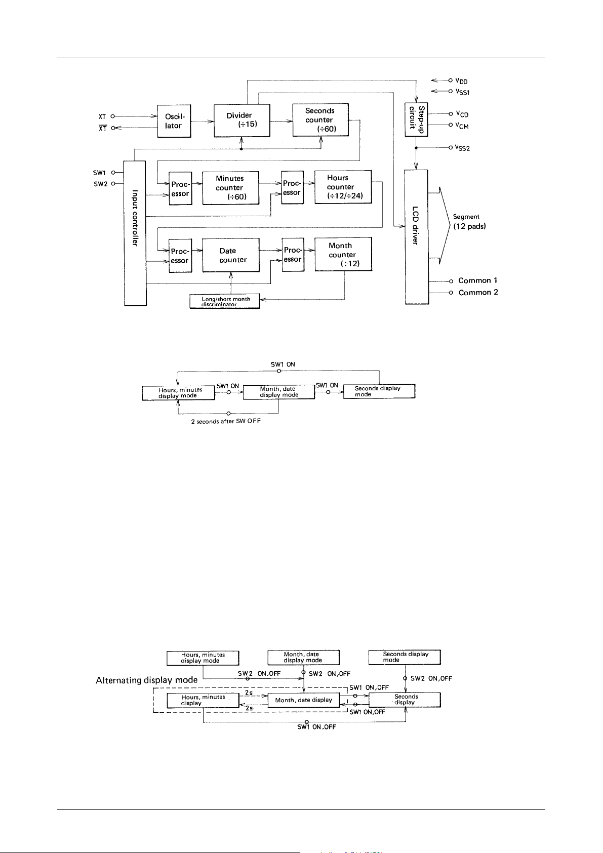
Block Diagram
Operating Specification
LC5645N
1.Hours, minutes display mode
• In this hours, minutes display mode the colon flashes at a 1Hz rate and 50% duty.
• The 10’s digit of hours is zero-blanked.
• In the 12-hour operation mode the hours digits change as 1 → 2 →............→ 12 → 1.
• In the 24-hour operation mode the hours digits change as 0 → 1 →....................... → 23 → 0.
2.Month, date display mode
• In the month, date display mode the colon is unlighted.
• The 10’s digit of both month and date is zero-blanked.
• Discrimination between long month and short month is exercised when an hour carry occurs and February date is
counted up to 28th.
3.Seconds display mode
• In the seconds display mode the colon flashes.
• Seconds are displayed on the right 2 digits, with the left 2 digits blanked.
4. Alternating display mode
• By pushing switch S2 in the hours, minutes display mode or month, date display mode, the alternating display
mode is entered. By pushing switch S2 and then switch S1 in the seconds display mode, the alternating display
mode is also entered.
• When the alternating display mode is entered, the month, date display appears. The hour, minutes display
appears 2 seconds later, and then the month, date display returns 2 seconds later. This is repeated.
No.1433–3/10
Page 4

5.Time setting mode
LC5645N
• Only the digit to be set is lighted and displayed. In the month setting mode the month digits only are displayed.
• In the month or hours setting mode the month or hours are displayed on the left 2 digits.
In the date or minutes setting mode the date or minutes are displayed on the right 2 digits.
• In the hours or minutes setting mode the colon is lighted.
In the month or date setting mode the colon is unlighted.
• Each time SW1 is pushed/released in each setting mode, the display contents are incremented +1. Holding SW1
pushed for 1 to 2 seconds or more causes the display contents to advance at a 4Hz rate.
• Execution of setting in each setting mode
(a) Execution of month setting ........... The month counter counts up to 12.
(b) Execution of date setting............... The date counter counts up to 31 regardless of long/short month.
No carry to the month digits occurs. Discrimination between long month
and short month is exercised only when a carry from the hours digits
occurs.
(c) Execution of hours setting............. In the 12-hour operation mode “A” is displayed on the rightmost digit
when in the morning : “P” is displayed when in the afternoon.
The display contents change as 11a.m. → 12p.m. → 1p.m. or 11p.m →
12a.m. → 1a.m.
In the 24-hour operation mode the display contents change as 23 → 0.
No carry to the date digits occurs.
(d) Execution of minutes setting........ When minutes setting is executed, seconds are cleared and the time is
held as set. This is proved by the fact that when SW2 is pushed/released
after execution of minutes setting the hours, minutes display appears but
the colon remains lighted without flashing. By pushing/releasing SW1 or
SW2 under this state, the time hold is released, timekeeping starts, and
the normal hours, minutes display mode returns with the colon flashing.
If in the minutes setting mode SW2 is pushed/released without execution
of minutes setting, the setting mode returns to the normal hours, minutes
display mode.
No.1433–4/10
Page 5

LC5645N
Sample Display of Each Mode
1.Hours, minutes display mode 6. Hours setting mode
(For the alternating display mode also, this applies.)
Colon : Flashing at a 1Hz rate (50% duty)
Hour, minutes display (12 :54) 12-hour operation mode Hours only
2. Month, date display mode
(For the alternating display mode also, this applies.)
Colon : Unlighted (10p.m.)
Month, date display (July 30)
3. Seconds display mode
Colon : Lighted
Colon : Lighted
12-hour operation mode Hours only
Indicating AM
(9a. m.)
Indicating PM
Colon : Unlighted (23)
Second display (08)
4. Month setting mode
Colon : Unlighted
Month only (June) 8. Hold mode
5. Date setting mode
Colon : Unlighted
Date only (7)
Colon : Lighted
24-hour operation mode Hours only
7. Minutes setting mode
Colon : Lighted
Minutes only (45)
Colon : Lighted
Hours, minutes display (8 : 29)
No.1433–5/10
Page 6

LC5645N
Others
1.Zero blanking.............. Unnecessary 0’s are unlighted.
Unlighted content ....... The 10’s digit of month, date, hours is zero-blanked.
Lighted content........... 0 in the 10’s digit of minutes, seconds is lighted.
2.Switch input voltage
The INPUT pin contains a floating preventing resistor. VDD is applied to this pin to start operation.
3.24/12-hour operation mode select
For the 12-hour operation mode, the 24H/12H pin is not bonded. For the 24-hour operation mode, this pin is
bonded.
4.Setting pulse
Each time SW1 is pushed in each setting mode, the display contents are incremented +1. Holding SW1 pushed
causes fast advance at a 4Hz rate to start approximately 1 second later.
5.Switch chattering preventer
Chattering of 30ms or less is prevented. (More than 30ms is considered to be bounding.)
6.Step-up circuit
Two capacitors (0.1µF) are connected externally. The step-up frequency is 512Hz.
7.Initial clear
The circuit is built in. The initial mode can be also entered by pushing SW1 and SW2 simultaneously.
8.LCD output alternating frequency .... 32Hz
Supply current
Unit (capacitance : F)
(Note) • Pins not entered are all open.
• CI≤25kΩ
No.1433–6/10
Page 7

LC5645N
Oscillation start voltage, oscillation stop voltage, oscillation start time.
Common-segment time lag
Segment
Common
Sample Application Circuit
LCD Format (12 hour display format)
No.1433–7/10
Page 8

LCD Format (24 hour display format)
Pad No. and Pin Name
LC5645N
Pad No.
1
2
3
4
5
6
7
8
9
10
11
12
13
14
15
16
17
Pin Name
V
DD
VCP (Cup2)
V
(Cup1)
CM
Test2
32Hz
Test 1
V
SS1
S2
V
DD
24H/12H
V
SS2
Test 3
Test 4
S1
Common 1
B4/C4
A4/G4
X coordinates (µm)
1407
1407
1407
1225
1045
–1193
–1407
–1407
–1407
–1407
–1407
–1407
–1407
–1407
–1125
–945
–765
Y coordinates (µm)
450
630
822
822
822
822
822
630
450
270
90
–90
–270
–450
–822
–822
–822
Pad No.
18
19
20
21
22
23
24
25
26
27
28
29
30
31
32
33
34
Pin Name
F4/E4
B3/C3
AD3/G3
F3/E3
C
1/D4
O
B2/C2
A2/G2
F2/E2
B1/D2
24S/C1
Common 2
Lamp
XT (Osc Out)
10pF
XT (Osc In)
Monitor
Monitor
* The pad coordinates are such that the pellet center is taken as the origin (0.0).
X coordinates (µm)
–585
–405
–225
–45
135
315
495
675
855
1035
1407
1407
1407
1407
1407
1407
1407
Y coordinates (µm)
–822
–822
–822
–822
–822
–822
–822
–822
–822
–822
–822
–467
–90
90
270
–630
–322
No.1433–8/10
Page 9

LC5645N
Specifications
Absolute Maximum Ratings at Ta = 25˚C, VDD=0V
retemaraPlobmySsnoitidnoCsgnitaRtinU
1egatlovylppusmumixaMV
2egatlovylppusmumixaMV
egatlovtupnIV
1egatlovtuptuOV
2egatlovtuptuOV
erutarepmetgnitarepOrpoT 57+ot02–
erutarepmetegarotSgtsT 521+ot03–
Recommended Operating Conditions at Ta = 25˚C, VDD=0V
retemaraPlobmySsnoitidnoCsgnitaRtinU
1egatlovylppuSV
2egatlovylppuSV
egatlovlevelhgihtupnIV
egatlovlevelwoltupnIV
Electrical Characteristics at T a =25˚C, VDD=0V, VSS=–1.3 to –1.65V
retemaraPlobmySsnoitidnoC
ecnatsisertupnIR
ecnatsisertupnIR
ecnatsisertupnIR
ecnatsisertupnIR
egatlovlevel"H"tuptuOV
egatlovlevel"L"tuptuOV
egatlovlevel"H"tuptuOV
egatlovlevel"M"tuptuOV
egatlovlevel"L"tuptuOV
tnerrucegakaeltupnII
egatlovpu-petSV
tnerrucylppuSI
egatlovtratsnoitallicsOV
egatlovdlohnoitallicsOV
emittratsnoitallicsOt
)nipFp01(ecnaticapacnoitallicsOC
galemittnemges-nommoCt
ecnaticapaCni-tliuBC
1SS
2SS
NI
1TUO
2TUO
1SS
V
2SS
V
HI
V
LI
V
1NI
2NI
3NI
4NI
1HO
1LO
2HO
MO
2LO
ffo
2SS
DD
DLOH
TRATS
o
D
D
1SS
V
1SS
V
1SS
V
1SS
V
1SS
V
1SS
V
1SS
V
1SS
V
1SS
V
1SS
C1C=
f
gpo
V
1SS
C1C=
TRATS
C1C=
V
1SS
V
2SS
V,zH23,TX
PC
1SS
1SS
1SS
2nommoC
V,V2–=
2
k52=IC Ω
2
2
k52=IC Ω
56.1–ot3.1–=4.2–ot3.3–V
S,V55.1–=
1S,2
S,V55.1–=
1S,2
S,V55.1–=
I,V55.1–=
I,V55.1–=
I,V55.1–=
I,V55.1–=
I,V55.1–=
2SS
M3,Fµ1.0= Ω Vssorca
zHk867.23=
C,V55.1–=
C,Fµ1.0=
C,Fµ1.0=
C,V55.1–=
1S,2
HO
LO
HO
HO
LO
1C=2
oC=g
oC=g
1C=2
pmaL,0020002kΩ
tupnitset,V55.1–=1001kΩ
I,Aµ4–=
LO
DD
C,Fµ1.0=
C,Fµ1.0=
C,V5.2–ot3.3–=
p001=001–001+sµ
L
3.0+ot4–V
3.0+ot4–V
H21/H42,TX,4Tot1T,PMAL,2S,1SV
V,2nommoC,1nommoC,stnemgesllA
MC
nimpytxam
H21/H42,rTdlohlevel"L",V55.1–=01001kΩ
H21/H42,rTni-lluplevel"L",V55.1–=0020002kΩ
noloc,tnemges,Aµ4.0–=2.0–V
noloc,tnemges,Aµ4.0=
2nommoC,1nommoC,Aµ4–=2.0–V
,1nommoC,Aµ4=
V
1SS
2nommoC,1nommoC,Aµ4=
edomffoH21/42,V4–=1.0Aµ
V–
,
2SS
oC=g
oC=g
,Fp02=
k52=IC,Fp02= Ω 54.1–V
k52=IC,Fp02= Ω 3.1–V
,Fp02=
1SS
V
1SS
V
2SS
V
1SS
sgnitaR
2.0–V
3.3–5.2–V
0.10.2Aµ
821Fp
02Fp
3.0+ot3.0–V
3.0+ot3.0–V
3.0+ot3.0–V
3.1–ot56.1–V
0+ot2.0–V
V+ot
2.0+V
1SS
V
2.0+
2SS
2.0+
1SS
V
2.0+
2SS
01s
˚C
˚C
tinU
V
V
V
No.1433–9/10
Page 10

LC5645N
Specifications of any and all SANYO products described or contained herein stipulate the performance,
characteristics, and functions of the described products in the independent state, and are not guarantees
of the performance, characteristics, and functions of the described products as mounted in the customer's
products or equipment. To verify symptoms and states that cannot be evaluated in an independent device,
the customer should always evaluate and test devices mounted in the customer's products or equipment.
SANYO Electric Co., Ltd. strives to supply high-quality high-reliability products. However, any and all
semiconductor products fail with some probability. It is possible that these probabilistic failures could
give rise to accidents or events that could endanger human lives, that could give rise to smoke or fire,
or that could cause damage to other property. When designing equipment, adopt safety measures so
that these kinds of accidents or events cannot occur. Such measures include but are not limited to protective
circuits and error prevention circuits for safe design, redundant design, and structural design.
In the event that any or all SANYO products(including technical data,services) described or
contained herein are controlled under any of applicable local export control laws and regulations,
such products must not be exported without obtaining the export license from the authorities
concerned in accordance with the above law.
No part of this publication may be reproduced or transmitted in any form or by any means, electronic or
mechanical, including photocopying and recording, or any information storage or retrieval system,
or otherwise, without the prior written permission of SANYO Electric Co. , Ltd.
Any and all information described or contained herein are subject to change without notice due to
product/technology improvement, etc. When designing equipment, refer to the "Delivery Specification"
for the SANYO product that you intend to use.
Information (including circuit diagrams and circuit parameters) herein is for example only ; it is not
guaranteed for volume production. SANYO believes information herein is accurate and reliable, but
no guarantees are made or implied regarding its use or any infringements of intellectual property rights
or other rights of third parties.
This catalog provides information as of May, 2001. Specifications and information herein are subject to
change without notice.
PS No.1433–10/10
 Loading...