

SANYO LB1965M Datasheet
Ordering number : ENN6189
LB1965M
Monolithic Digital IC
LB1965M
Two-Phase Unipolar Driver
for Variable-Speed Fan Motor
Features
• With only a few peripheral parts including a thermistor,
ambient temperature dependent continuous speed control
can be implemented. This allows low-speed startup
(100% duty drive at startup).
• Settable minimum rotation speed for low temperature
• Built-in thermistor voltage amplification circuit assures
high precision of ambient temperature to rotation speed
ratio
• Built-in motor lockup protection and automatic recovery
circuit
Output current Io = 1.5A, built-in output stage protection
Zener diode
–> Low-noise protection with chip capacitors also
possible
• Built-in thermal protection
• FG output
• Direct Hall element connection possible
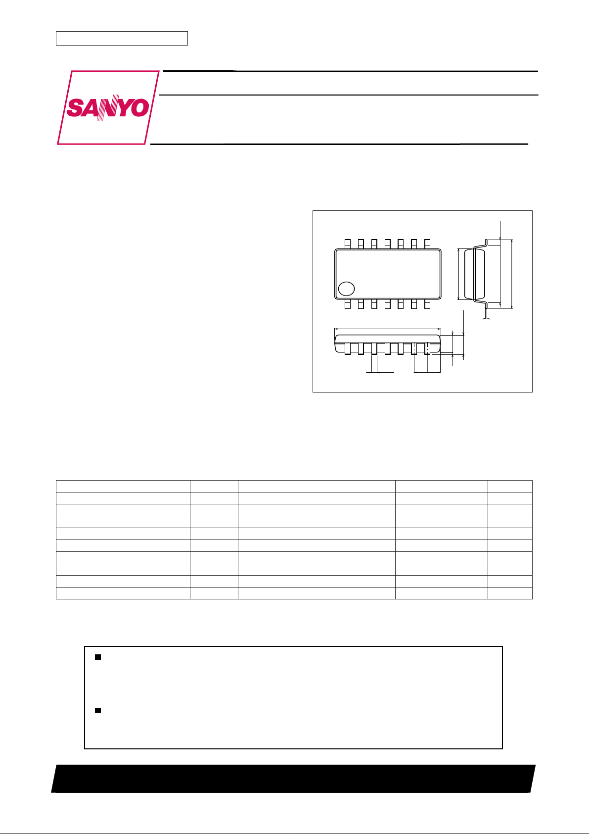
Package Dimensions
unit: mm
3111-MFP14S
[LB1965M]
14
1
8.0
0.35
1.0
8
4.4
7
1.0
0.15
1.8max
1.50.1
SANYO : MFP14S
0.625
5.15
6.4
Specifications
Absolute Maximum Ratings at Ta = 25˚C
Parameter Symbol Conditions Ratings Unit
Maximum input current ICC max t ≤ 20 ms 200 mA
Maximum applied output voltage VOUT max Internal V
Maximum output current I out max 1.5 A
Current flowing into FG IRD max 10 mA
FG applied voltage VRD max 50 V
Allowable power dissipation Pd max Mounted on a specified PCB 0.8 W
(114.3 × 76.1 × 1.5 mm3 glass epoxy)
Operating temperature Topr –30 to +85 °C
Storage temperature Tstg –55 to +150 °C
Any and all SANYO products described or contained herein do not have specifications that can handle
applications that require extremely high levels of reliability, such as life-support systems, aircraft's
control systems, or other applications whose failure can be reasonably expected to result in serious
physical and/or material damage. Consult with your SANYO representative nearest you before using
any SANYO products described or contained herein in such applications.
SANYO assumes no responsibility for equipment failures that result from using products at values that
exceed, even momentarily, rated values (such as maximum ratings, operating condition ranges, or other
parameters) listed in products specifications of any and all SANYO products described or contained
herein.
SANYO Electric Co.,Ltd. Semiconductor Company
TOKYO OFFICE Tokyo Bldg., 1-10, 1 Chome, Ueno, Taito-ku, TOKYO, 110-8534 JAPAN
83100RM(KI)
No. 6189-1/6
LB1965M
412
0
3
Allowable Operating Ranges at Ta = 25˚C
Parameter Symbol Conditions Ratings Unit
Input current range ICC 6.0 to 50 mA
Hall amplifier common mode input VICM 0 to VIN–1.5 V
voltage range
RMI input voltage range VRMI 0.3 to VIN V
Rth input voltage range VICM 0 to VIN–1 V
Electrical Characteristics at Ta = 25˚C, ICC = 10 mA
Parameter Symbol Conditions
Output limiter voltage VoLM1 Io = 0.1A 30 32 34 V
Vosat1 Io = 0.5A 0.95 1.2 V
Output saturation voltage Vosat2 Io = 1.0A 1.15 1.5 V
Vosat3 Io = 1.5A 1.4 2.0 V
Input voltage VIN Icc = 7.0 mA 6.4 6.7 7.0 V
Amplifier input offset voltage VOFF –7.0 0 7.0 mV
Amplifier input bias current IBA –250 nA
FG output saturation voltage VFG(sat) IFG = 5 mA 0.15 0.3 V
C charge voltage IC1 C = GND 2.7 3.9 5.0 µA
C discharge voltage IC2 C = VIN 0.35 0.50 0.65 µA
Comp input threshold voltage VTH1 0.77 0.8VIN 0.83 V
VTH2 0.42 0.45VIN 0.48 V
Ct discharge voltage VCT 0.20 0.22VIN 0.24 V
Rt input current Irt VRT = GND 1 3 µA
VRt amplification VRt RT = OPEN 1.52 1.56 1.60 times
RMI offset voltage VRMIoff –7 0 +7 mA
Thermal protection operating voltage TSD Design target value* 150 180 210 ˚C
* Design target values are not measured.
Ratings
min typ max
Unit
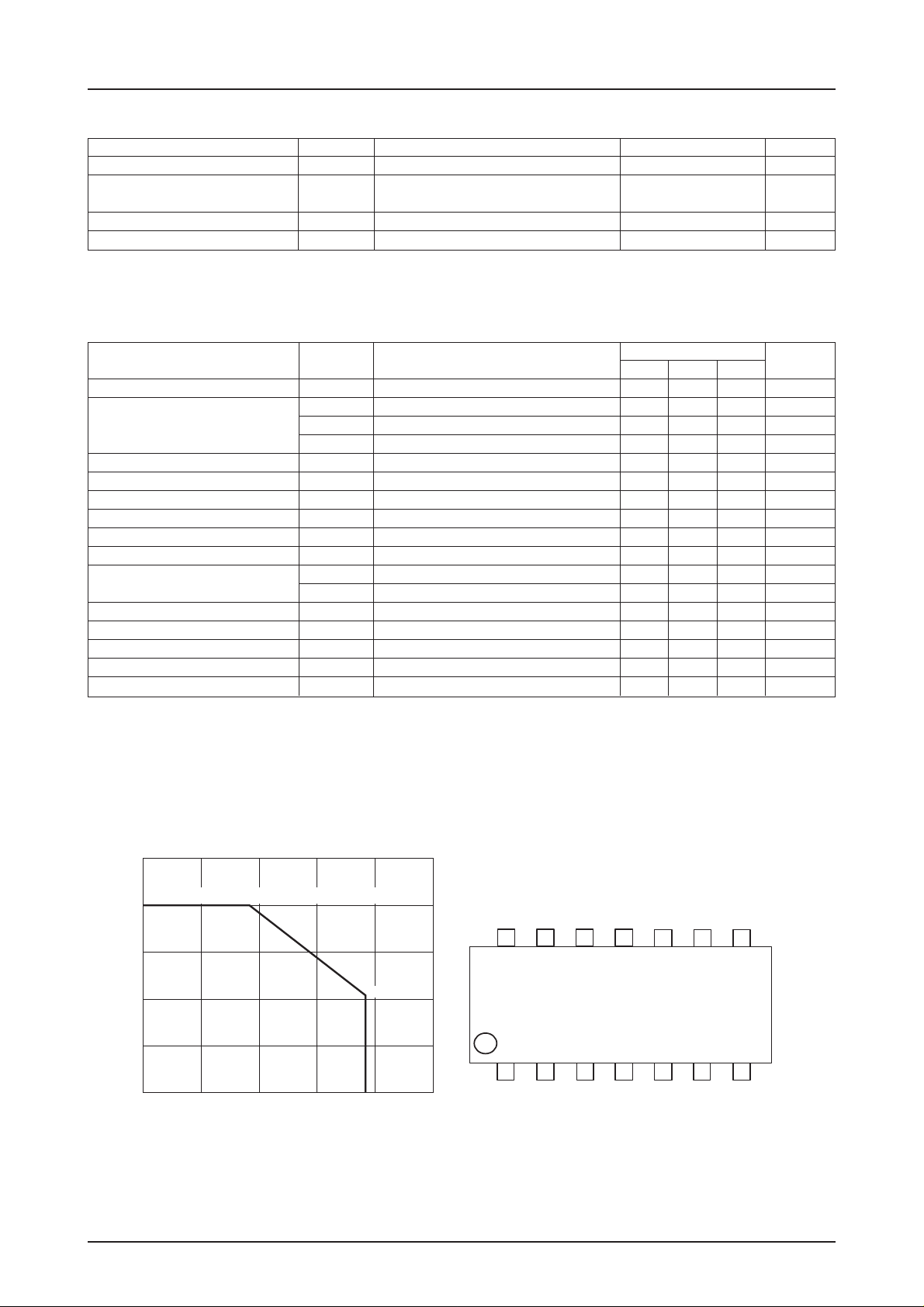
1000
Specified substrate (114.3 × 76.1 × 1.5 mm3) glass epoxy
800
600
400
200
Allowable power dissipation, Pd max – mW
0
–30 0 30 60 85 90 120
Pd max – Ta
416
Ambient temperature, Ta – °C
Pin Assignment
1
FG
VIN
NC
IN–
1 2
111
Ct
Rth
LB1965M
CR
IN+
3 4
1
9 8
RMI
OUT2
B1
OUT1
5 6 7
B2
GND
(Top View)
No. 6189-2/6
 Loading...