

SANYO LB1960M Datasheet
Ordering number : EN6191
LB1960M
Monolithic Digital IC
LB1960M
Fan Motor 2-Phase Half-Wave Driver
Features
• Dual power supply voltage design (5/12V) and wide voltage
handling range
(3V also supported for rotation functions only)
• Constant-voltage Hall bias power supply (1.3V across HBGND) assures stable Hall output over entire temperature and
power supply voltage range. External limiting resistor not
required.
• Built-in Hall amplifier with hysteresis (supports core
without commutating pole)
• Built-in lockup protection and automatic recovery circuits
(External capacitor for rotation detection need only be 0.1
µF, allowing compact, cost-saving design)
• Built-in output transistor with output withstand voltage
24Vmax/output current 500 mA (average), 1A (peak)
• Built-in thermal protection circuit
• Compact MFP-8 package. Low external parts count, easy
wiring, and small PCB area allow use also with miniature
fan motors.
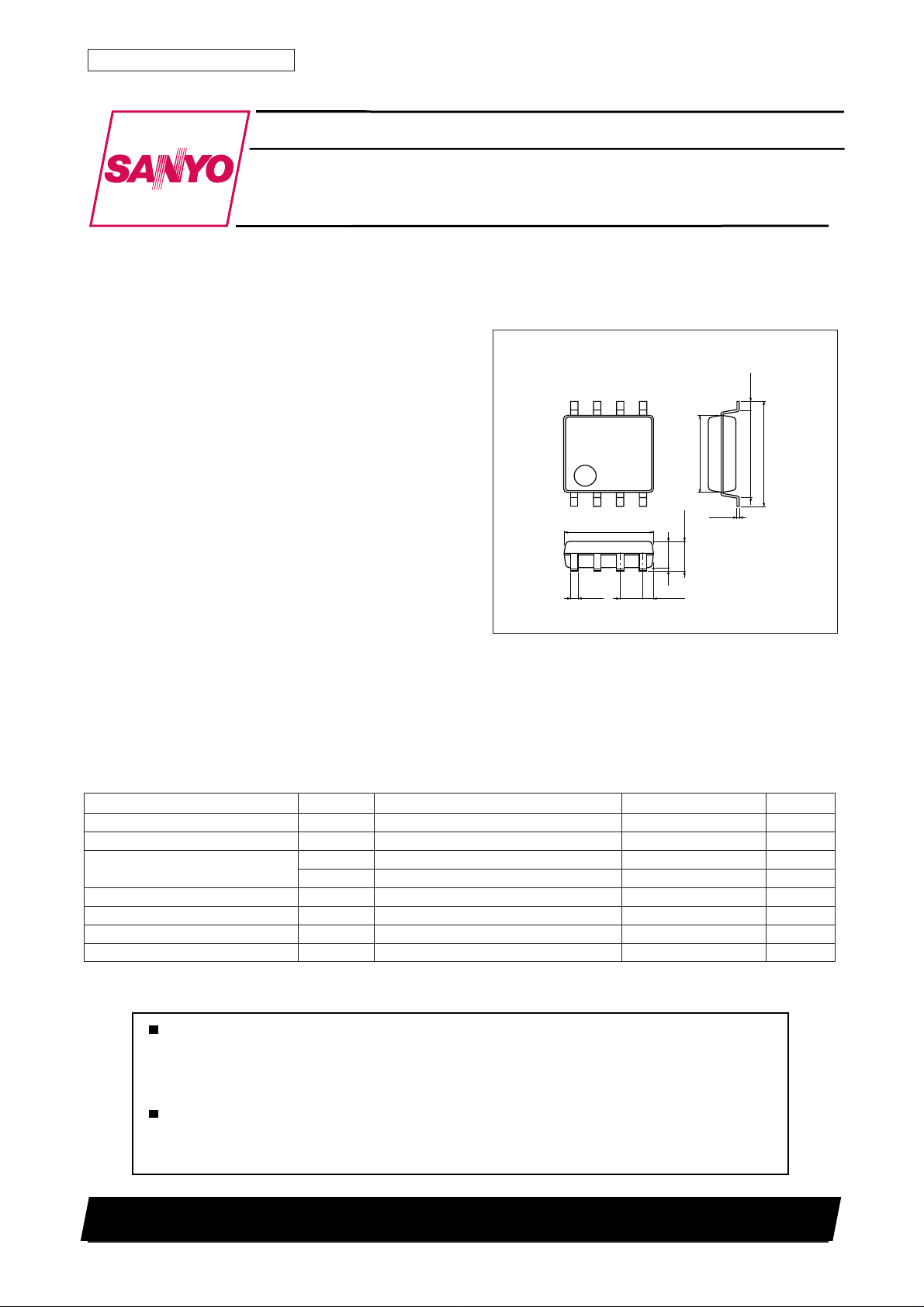
Package Dimensions
unit: mm
3032B-MFP8
[LB1960M]
8
1
5.1
5
4
0.645
1.270.35
1.50.1
4.4
1.8max
0.625
5.15
0.15
SANYO : MFP8
6.4
Specification
Absolute Maximum Ratings at Ta = 25°C
Parameter Symbol Conditions Ratings Unit
Maximum supply voltage VCC max 18 V
Allowable power dissipation Pd max With specified substrate * 600 mW
Maximum output current I
Maximum output voltage V
Maximum HB output current IH max 10 mA
Operating temperature
Storage temperature Tstg –55 to +150 °C
* Specified substrate (1 14.3 × 76.1 × 1.5 mm3, glass epoxy)
Any and all SANYO products described or contained herein do not have specifications that can handle
applications that require extremely high levels of reliability, such as life-support systems, aircraft's
control systems, or other applications whose failure can be reasonably expected to result in serious
physical and/or material damage. Consult with your SANYO representative nearest you before using
any SANYO products described or contained herein in such applications.
SANYO assumes no responsibility for equipment failures that result from using products at values that
exceed, even momentarily, rated values (such as maximum ratings, operating condition ranges, or other
parameters) listed in products specifications of any and all SANYO products described or contained
herein.
ave 500 mA
OUT
I
peak t ≤ 1 ms 1000 mA
OUT
max Internal V
OUT
Topr
–30 to +85 °C
SANYO Electric Co.,Ltd. Semiconductor Company
TOKYO OFFICE Tokyo Bldg., 1-10, 1 Chome, Ueno, Taito-ku, TOKYO, 110-8534 JAPAN
63099RM(KI)
No. 6191-1/4
LB1960M
Allowable Operating Ranges at Ta = 25°C
Parameter Symbol Conditions Ratings Unit
Recommended supply voltage VCC 1 3.6 to 17 V
Common mode input voltage range VCOM 0.2 to HB V
Electrical Characteristics at Ta = 25°C, VCC = 12V
Parameter Symbol Conditions
Circuit current I
In drive mode (CT = L) 2.3 4 mA
CC
In lockup protection mode (CT = H) 3 5 mA
CT capacitor charge current ICT1VCT = 0.2V 0.8 1.2 2.0 µA
Capacitor discharge current ICT2VCT = 8V 0.16 0.24 0.4 µA
Capacitor charge/discharge current
ratio
R
CT
R
= ICT1/ICT2 4.0 5.0 7.0 –
CT
CT charge voltage VCT1 6.8 7.2 7.6 V
CT discharge voltage VCT2 1.4 1.6 1.8 V
Output limiter withstand voltage V
OLM
Io = 1 mA 22.5 23.5 24.5 V
Output saturation voltage VOsat Io = 500 mA 1.0 1.3 V
Hall input sensitivity V
HB output H voltage V
Thermal protection trigger temperature T
HBH
Including offset and hysteresis 6 12 mV
HN
RH = 350Ω 1.1 1.3 1.5 V
Assured design target* 150 180 210 ˚C
TSD
* Assured design target: Target value, not measured individually
Ratings
min typ max
Unit
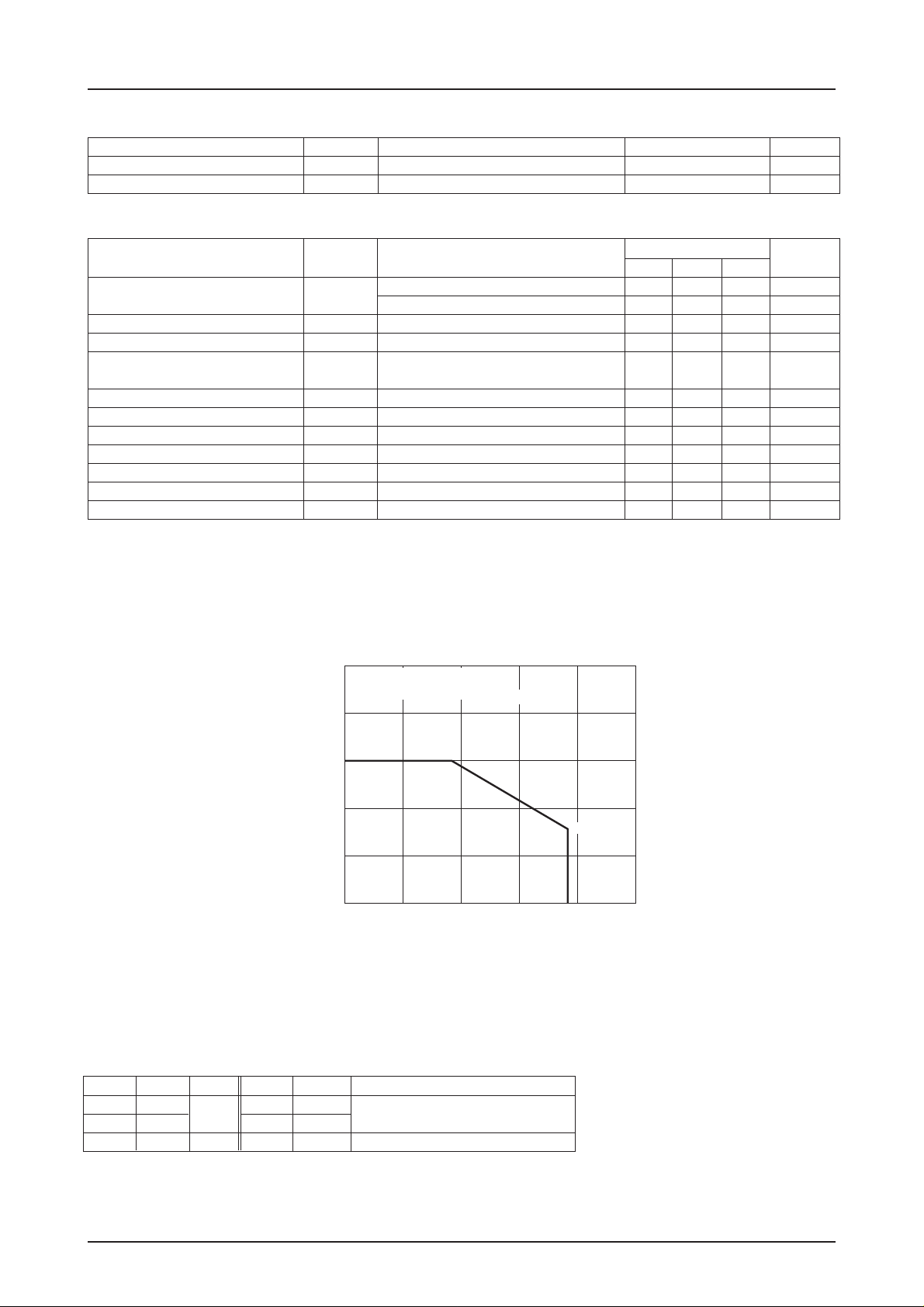
1000
Specified substrate
Pd max – Ta
(glass epoxy, 114.3×76.1×1.5mm
800
600
400
200
Allowable power dissipation, Pd max – mW
0
–30 0 30 60 90 120
Ambient temperature, Ta – °C
Truth Table
IN– IN+ CT OUT1 OUT2 Mode
H L L L H Rotating
LH HL
– – H off off Lock-up protection activated
3
)
312mW
No. 6191-2/4
 Loading...