

SANYO LB1863M, LB1869M Datasheet
Overview
The LB1863M and LB1869 (LB1669M) are 2-phase
unipolar brushless motor drivers that are provided in a
miniature flat package that contributes to end product
miniaturization and supports automatic mounting. These
products support the implementation of motor drive lock
protection and automatic recovery circuits, and alarm
specifications with a minimal number of external
components.
Features and Functions
• Hall elements can be connected directly to the IC itself.
• 1.5-A output current output transistors built in
• Rotation detection function that provides a low-level
output during motor drive and a high-level output when
the motor is stopped
• Motor lock protection and automatic recovery functions
built in
• Thermal shutdown circuit
• Switching noise can be reduced with an external ceramic
capacitor.
Classification
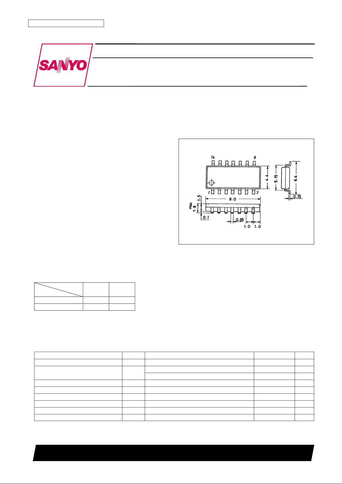
Package Dimensions
unit: mm
3111-MFP14S
Monolithic Digital IC
Ordering number : N4943
13097HA (OT) No. 4943-1/5
SANYO: MFP14S
[LB1863M, 1869M]
SANYO Electric Co.,Ltd. Semiconductor Bussiness Headquarters
TOKYO OFFICE Tokyo Bldg., 1-10, 1 Chome, Ueno, Taito-ku, TOKYO, 110 JAPAN
Two-Phase Unipolar Brushless Motor Driver
Automatic Recovery Type Circuit in a Miniature Flat Package
LB1863M, 1869M
Package
MFP-10S MFP-14S
System voltage
12 V LB1669M LB1869M*
24 V LB1863M*
Note: * The LB1869M and LB1863M are pin compatible
so that the same printed circuit board can be
used for both 12 V and 24 V products.
Parameter Symbol Conditions Ratings Unit
Maximum input current I
CC
max t ≤ 20 ms 200 mA
Output voltage V
OUT
LB1863M –0.3 to +85 V
LB1869M –0.3 to +60 V
Output current I
OUT
1.5 A
RD influx current I
RD
10 mA
RD voltage V
RD
30 V
Allowable power dissipation Pd max
When mounted (on a 20 × 15 × 1.5-mm3glass-epoxy printed circuit board)
800 mW
Operating temperature Topr –30 to +80 °C
Storage temperature Tstg –55 to +150 °C
Specifications
Absolute Maximum Ratings at Ta = 25°C

No. 4943-2/5
LB1863M, 1869M
Parameter Symbol Conditions Ratings Unit
Input current range I
CC
6.0 to 50 mA
Common-mode input voltage range V
ICM
0 to VIN–1.5 V
Allowable Operating Ranges at Ta = 25°C
Parameter Symbol Conditions
Ratings
Unit
min typ max
Output voltage 1 V
OR
LB1863M 80 V
LB1869M 60 V
Output voltage 2 V
O(SUS)
LB1863M : IO= 0.1 A 65 V
LB1869M : I
O
= 0.1 A 40 V
Output saturation voltage
V
O
(sat)1 IO= 0.5 A 0.95 1.2 V
V
O
(sat)2 IO= 1.0 A 1.15 1.5 V
Input voltage V
INICC
= 7.0 mA 6.4 6.7 7.0 V
Amplifier input offset voltage V
OFF
–7 0 7.0 mA
Amplifier input bias current I
BA
–250 nA
RD output saturation voltage V
RD
(sat) IRD= 5 mA 0.1 0.3 V
Capacitor discharge current
I
C
1 2.1 3 3.9 µA
I
C
2 0.31 0.44 0.59 µA
Comparator input threshold voltage
V
TH
1 0.77 0.8V
IN
0.83 V
V
TH
2 0.42 0.45V
IN
0.48 V
Electrical Characteristics at Ta = 25°C, ICC= 10 mA
Pin Assignment
 Loading...