

SANYO LB1840M Datasheet
Ordering number: EN4996
Monolithic Digital IC
LB1840M
Low-voltage/Low-saturation Bidirectional
Variable Constant-voltage Motor Driver
Overview
The LB1840M is a low-voltage, low-saturation, three-input
type two-channel bidirectional motor driver that permits
switching between constant-voltage regulated output and
saturated output. The design is ideal for a two-phase bipolar
driver for stepping motors.
Features
.
Wide operating voltage range (3.0 to 9.0 V).
.
Low saturation voltage
V
= 0.40 V at IO= 200 mA.
O(sat)
.
Consumes almost no current in standby mode
(0.1 µA or less).
.
Permits setting of bidirectional constant-voltage regulated
value.
.
Three-input type that is ideal for a two-phase bipolar driver.
.
Permits switching between constant-voltage regulated output
and saturated output.
.
Built in reference voltage coupled to input.
.
Compact MFP-14S package.
Specifications
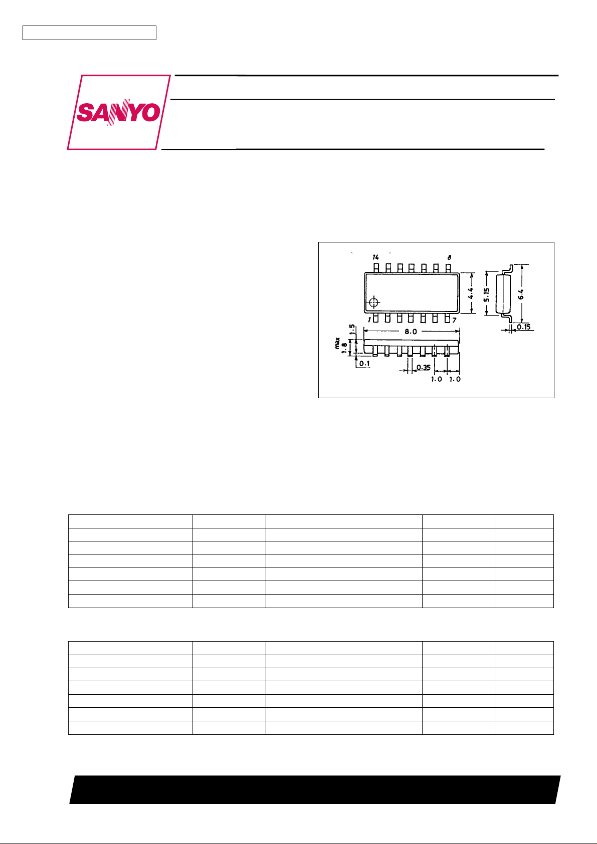
Package Dimensions
unit: mm
3111-MFP14S
[LB1840M]
SANYO : MFP14S
Absolute Maximum Ratings atTa=25°C
Parameter Symbol Conditions Ratings Unit
Maximum supply voltage V
Output current Im max 250 mA
Applied input voltage V
Allowable power dissipation Pd max With board ( 30 × 30 × 1.5 mm
Operating temperature Topr –20 to +80 °C
Storage temperature Tstg –40 to +150 °C
max 10.5 V
CC
IN
3
) 800 mW
–0.3 to +10 V
Allowable Operating Ranges atTa=25°C
Parameter Symbol Conditions Ratings Unit
Supply voltage V
IN pin high level voltage V
IN pin low level voltage V
Control voltage V
VM pin high level voltage VM
VM pin low level voltage VM
CC
INH
INL
C
H
L
3.0 to 9.0 V
3.0 to 9.0 V
–0.3 to +0.7 V
0.2 to 6.0 V
VCC– 0.3 to V
–0.3 to VCC–2.5 V
CC
SANYO Electric Co.,Ltd. Semiconductor Bussiness Headquarters
TOKYO OFFICE Tokyo Bldg., 1-10, 1 Chome, Ueno, Taito-ku, TOKYO, 110 JAPAN
O1596HA(II) No.4996-1/5
V
LB1840M
Electrical Characteristics at Ta = 25 °C, VCC=6V
Parameter Symbol Conditions min typ max Unit
Supply current I
Output saturation voltage V
Reference voltage V
Output voltage
voltage characteristics
Output voltage
current characteristics
Input current
Output voltage V
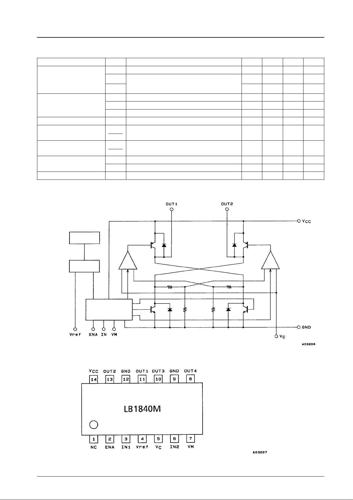
Equivalent Circuit Block Diagram
0 During standby 0.1 10 µA
CC
During bidirectional operation (for two channels):
I
1
CC
during control, load open
I
2 4.5 6.5 mA
during saturation, load open
CC
sat1IO
V
sat2IO
V
Osat3IO
refIVref
∆V
∆V
CC
∆V
∆I
O
I
IN
I
VM
O
= 100 mA (upper side + lower side) 0.30 0.40 V
= 200 mA (upper side + lower side) 0.40 0.55 V
= 200 mA (lower side) 0.07 0.10 0.15 V
= 1 mA 1.85 2.0 2.15 V
VO=5V,VCC= 5.5 to 9 V,
O
I
= 100 mA
O
VO=5V,VCC=6V,
O
I
=10to100mA
O
VIN= 5 V 90 150 µA
VM= GND 210 300 µA
Between OUT and GND
2.45 × V
3.5 5.0 mA
C
2.65 × V
20 mV
50 mV
V
C
(For one channel)
Thermal
Reference
voltage
Pin Assignment
Logic predriver
Note: Both GND pins must be grounded.
Top view
No.4996 -2/5
 Loading...