

Page 1
Any and all SANYO products described or contained herein do not have specifications that can handle
applications that require extremely high levels of reliability, such as life-support systems, aircraft’s
control systems, or other applications whose failure can be reasonably expected to result in serious
physical and/or material damage. Consult with your SANYO representative nearest you before using
any SANYO products described or contained herein in such applications.
SANYO assumes no responsibility for equipment failures that result from using products at values that
exceed, even momentarily, rated values (such as maximum ratings, operating condition ranges,or other
parameters) listed in products specifications of any and all SANYO products described or contained
herein.
Monolithic Linear IC
Narrowband FM IF Stage
Ordering number:ENN3890A
LA8604M
SANYO Electric Co.,Ltd. Semiconductor Company
TOKYO OFFICE Tokyo Bldg., 1-10, 1 Chome, Ueno, Taito-ku, TOKYO, 110-8534 JAPAN
Overview
The LA8604M is a narrowband FM IF stage IC that incorporates all the functional blocks for a complete IF stage,
including noise filtering, making it ideal for use in cordless
telephones.
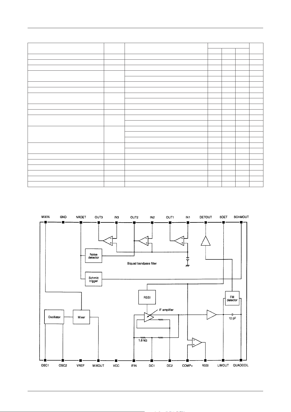
The LA8604M comprises a second-stage oscillator, a mixer ,
an IF amplifier, an FM detector, and noise detector , amplifier and rectifier circuits. A signal level meter output which
is linear over a wide dynamic range of up to 70dB is also
incorporated.
The LA8604M operates from a 2.4 to 6V supply and is
available in 24-pin MFPs.
Features
• On-chip mixer, IF amplifier and limiter.
• On-chip noise filter buffer.
• 70dB (typ) signal level meter linearity.
• Signal level meter output buffer.
• 2.4 to 6V supply.
• 24-pin MFP.
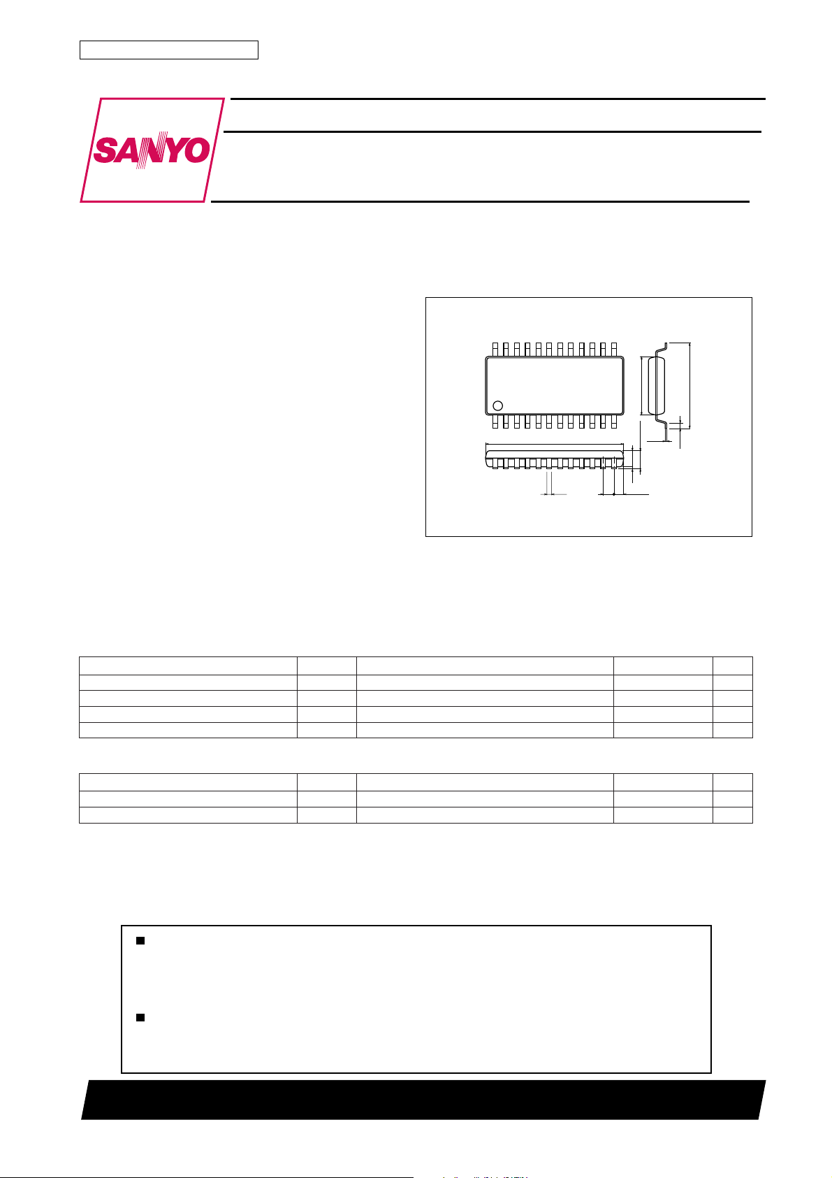
Package Dimensions
unit:mm
3112A-MFP24S
[LA8604M]
24
112
12.5
0.35
13
5.4
0.15
1.7max
1.5
0.1
1.0
(0.75)
SANYO : MFP24S
7.6
0.63
Specifications
Absolute Maximum Ratings at Ta = 25˚C
retemaraPlobmySsnoitidnoCsgnitaRtinU
egatlovylppusmumixaMV
noitapissidrewopmumixaMxamdP 003Wm
erutarepmetgnitarepOrpoT 57+ot02–
erutarepmetegarotSgtsT 521+ot04–
Operating Conditions at Ta = 25˚C
retemaraPlobmySsnoitidnoCsgnitaRtinU
egatlovylppusdednemmoceRV
egnaregatlovylppusgnitarepOV
xamCC
CC
po 0.6ot4.2V
CC
51001TN (KT)/9181TS No.3890–1/7
8V
˚C
˚C
3V
Page 2
LA8604M
Operating Characteristics at Ta = 25˚C, VCC=3V, fC=21.7MHz, fmod=1kHz, ∆f=±3kHz
retemaraPlobmySsnoitidnoC
tnerructnecseiuQI
ytivitisnesgnitimilBd3–SLBd3–V
egatlovtuptuonoitaludomeDV
oitaresion-ot-langiSN/S
oitarnoitcejernoitaludomedutilpmARMAnoitaludomMA%030304Bd
noitrotsidcinomrahlatoTDHTVIµBd08=7.00.2%
egatlovtuptuorotcetedesioNV
levelreggirt-ttimhcSHS018152µBd
siseretsyhreggirt-ttimhcSyhHS 1Bd
egatlovtuptuoreggirt-ttimhcSV
egatlovtuptuoretemlangiSV
egatlovtuptuoISSRV
niagnoisrevnocrexiMG
ycneuqerftupnirexiM 09zHM
ecnatsisertupnirexiM 6.3kΩ
ecnatsisertuptuorexiM 8.1kΩ
ecnatsisertupnireifilpmaFI 8.1kΩ
ecnadepmituptuorotcetedMF 4.2kΩ
OCC
I
V
O
DN
HS
MS
ISSR
M
µBd08=511071032Vm
I
V
I
V
I
V
µBd01=1.14.1V
I
V
µBd03=01.0V
I
V
µBd01= 5.0V
I
V
µBd52=8.2V
I
VIµBd5=1.03.0V
V
µBd05=8.01.14.1V
I
V
µBd08=3.16.10.2V
I
VIµBd5=8.2V
V
µBd53= 5.0V
I
tupniBd3–,µBd08=511µBd
noitaludomorez,µBd08=4506Bd
noitaludomorez,µBd02=0252Bd
sgnitaR
nimpytxam
8.28.3Am
02Bd
tinU
Block Diagram
No.3890–2/7
Page 3
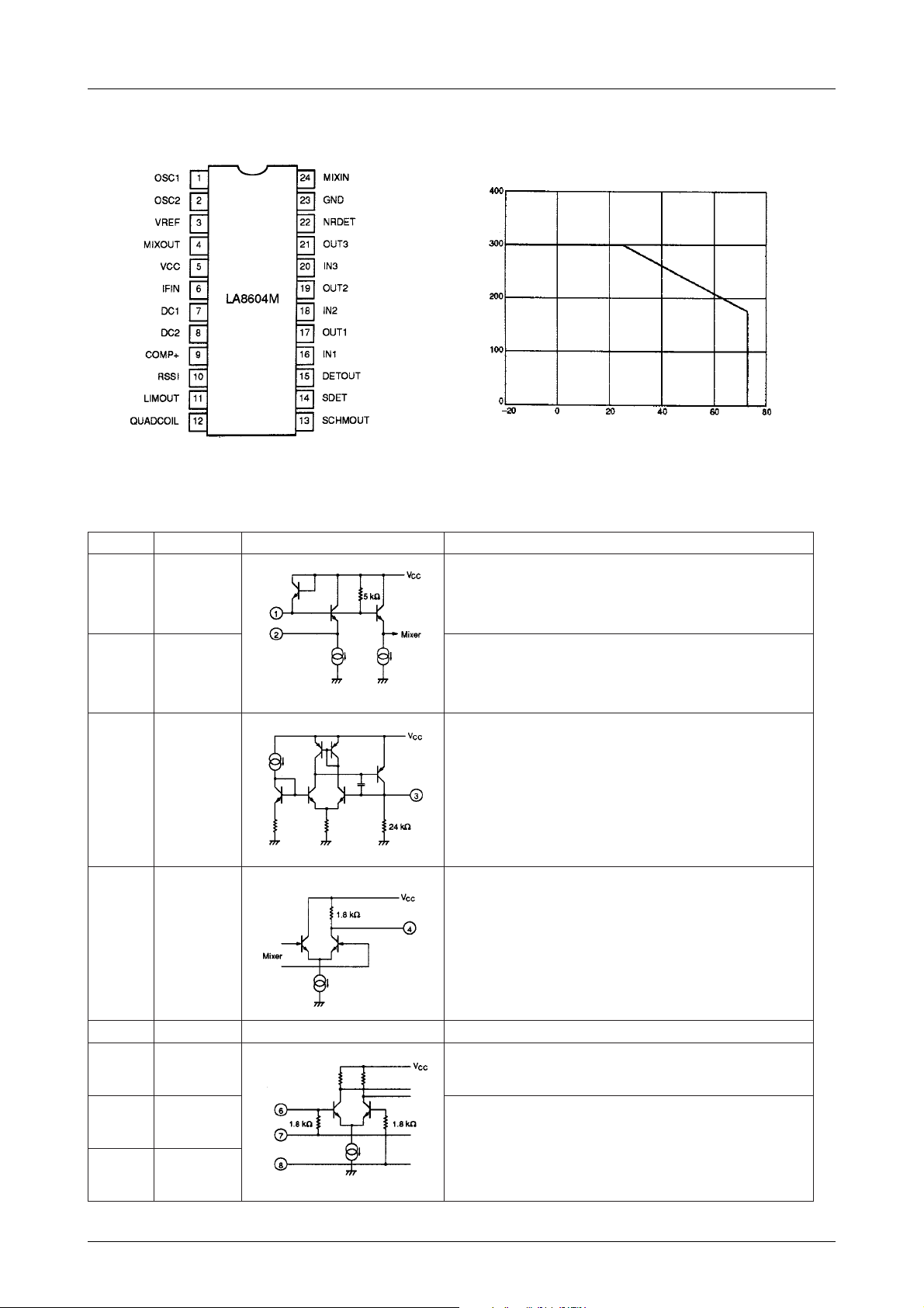
Pin Assignment
LA8604M
Pd max – Ta
Top view
Pin Functions
rebmuNemaNtiucrictnelaviuqEnoitpircseD
11CSO VsiegatlovlanimoN.noitcennoclatsyrcrotallicsosttiploC
22CSO VsiegatlovlanimoN.noitcennoclatsyrcrotallicsosttiploC
3FERV .tuptuoegatlovecnereferV2.1
Maximum power dissipation, Pd max – mW
Ambient temperature, Ta – °C
.
CC
.V7.0–
CC
4TUOXIM VsiegatlovlanimoN.tuptuoreffubrexiM
5V
6NIFI VsiegatlovlanimoN.tupnireifilpmaFI
71CD
82CD
CC
.V3.0–
CC
.egatlovylppuS
.V9.0–
CC
VsiegatlovlanimoN.snoitcennockrowtenkcabdeefreifilpmaFI
.V9.0–
CC
Continued on next page.
No.3890–3/7
Page 4

Continued from preceding page.
rebmuNemaNtiucrictnelaviuqEnoitpircseD
9+PMOC .tupnidlohserhtrotarapmocISSR
01ISSR .tuptuorotarapmocISSR,rotcelloc-nepO
11TUOMIL .V2.0siegatlovlanimoN.tuptuoreifilpmaretimiL
LA8604M
21LIOCDAUQ VsiegatlovlanimoN.noitcennockrowtengninutrotceteD
31TUOMHCS .tuptuoreggirt-ttimhcSrotarapmocesion,rotcelloc-nepO
41TEDS
51TUOTED .V2.1siegatlovlanimoN.tuptuorotcetedMF
611NI .V0.1siegatlovlanimoN.tupnignitrevni1reifilpmalanoitarepO
.
CC
.V5.1
ot1.0egnarehtnisiegatlovlanimoN.tuptuorotcetedhtgnertslangiS
711TUO .V0.1siegatlovlanimoN.tuptuo1reifilpmalanoitarepO
812NI .V0.1siegatlovlanimoN.tupnignitrevni2reifilpmalanoitarepO
912TUO .V0.1siegatlovlanimoN.tuptuo2reifilpmalanoitarepO
Continued on next page.
No.3890–4/7
Page 5

Continued from preceding page.
rebmuNemaNtiucrictnelaviuqEnoitpircseD
LA8604M
023NI
123TUO .V0.1siegatlovlanimoN.tuptuo3reifilpmalanoitarepO
22TEDRN .V4.1ot0egnarehtnisiegatlovlanimoN.tuptuorotcetedesioN
32DNGdnuorG
42NIXIM .V2.1siegatlovlanimoN.tupnirexiM
Test Circuit
.V0.1siegatlovlanimoN.tupnignitrevni3reifilpmalanoitarepO
No.3890–5/7
Page 6

Sample Application Circuits
LA8604M
Figure 1. Crystal detector
No.3890–6/7
Page 7

LA8604M
Figure 2. LC network detector
Specifications of any and all SANYO products described or contained herein stipulate the performance,
characteristics, and functions of the described products in the independent state, and are not guarantees
of the performance, characteristics, and functions of the described products as mounted in the customer's
products or equipment. To verify symptoms and states that cannot be evaluated in an independent device,
the customer should always evaluate and test devices mounted in the customer's products or equipment.
SANYO Electric Co., Ltd. strives to supply high-quality high-reliability products. However, any and all
semiconductor products fail with some probability. It is possible that these probabilistic failures could
give rise to accidents or events that could endanger human lives, that could give rise to smoke or fire,
or that could cause damage to other property. When designing equipment, adopt safety measures so
that these kinds of accidents or events cannot occur. Such measures include but are not limited to protective
circuits and error prevention circuits for safe design, redundant design, and structural design.
In the event that any or all SANYO products(including technical data,services) described or
contained herein are controlled under any of applicable local export control laws and regulations,
such products must not be exported without obtaining the export license from the authorities
concerned in accordance with the above law.
No part of this publication may be reproduced or transmitted in any form or by any means, electronic or
mechanical, including photocopying and recording, or any information storage or retrieval system,
or otherwise, without the prior written permission of SANYO Electric Co. , Ltd.
Any and all information described or contained herein are subject to change without notice due to
product/technology improvement, etc. When designing equipment, refer to the "Delivery Specification"
for the SANYO product that you intend to use.
Information (including circuit diagrams and circuit parameters) herein is for example only ; it is not
guaranteed for volume production. SANYO believes information herein is accurate and reliable, but
no guarantees are made or implied regarding its use or any infringements of intellectual property rights
or other rights of third parties.
This catalog provides information as of May, 2001. Specifications and information herein are subject to
change without notice.
PS No.3890–7/7
 Loading...